Embed Size (px)
Citation preview
86 Catalog – DRS-GM 06/2009
7 LubricantsDesign and Operating Notes
7 Design and Operating Notes7.1 LubricantsGeneral informa-tion
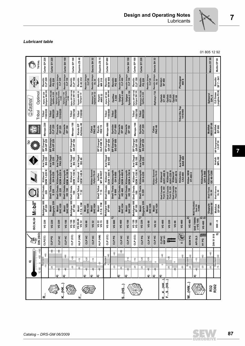
Unless a special arrangement is made, SEW-EURODRIVE supplies the drives with alubricant fill adapted for the specific gear unit and mounting position. The decisive factoris the mounting position (M1...M6, → section "Mounting positions and important orderinformation") specified when ordering the drive. You must adapt the lubricant fill in caseof any subsequent changes made to the mounting position (→ Lubricant fill quantities).
Lubricant table The lubricant table on the following page shows the permitted lubricants for SEW-EU-RODRIVE gear units. Observe the following legend with regards to the lubricant table.
Key to the lubricant table
Abbreviations, meaning of shading and notes:
Rolling bearing greases
The anti-friction bearings in gear units and motors are given a factory-fill with the greas-es listed below. SEW-EURODRIVE recommends regreasing rolling bearings with agrease fill at the same time as changing the oil or replacing the rolling bearings.
CLP = Mineral oilCLP PG = Polyglycol (W gear units, conforms to USDA-H1)CLP HC = synthetic hydrocarbonsE = Ester oil (water hazard class 1 (German regulation))HCE = synthetic hydrocarbons + ester oil (USDA - H1 certification)HLP = Hydraulic oil
= synthetic lubricant (= synthetic-based roller bearing grease)= mineral lubricant (= mineral-based rolling bearing grease)
1) Helical-worm gear units with PG oil: consult SEW-EURODRIVE.2) Special lubricant for Spiroplan® gear units only3) SEW-fB ≥ 1.2 required4) Pay attention to critical starting behavior at low temperatures!5) Low-viscosity grease6) Ambient temperature
Lubricant for the food industry (food grade oil)
Biodegradable oil (lubricant for agriculture, forestry, and fisheries)OilOil
Ambient temperature Manufacturer TypeGear unit rolling bear-ings -40 °C ... +80 °C Fuchs Renolit CX-TOM151)
1) Rolling bearing grease based on semi-synthetic base oil.
Motor rolling bearings2)
2) The motor rolling bearings are covered on both sides and cannot be regreased.
-20 °C ... +80 °C Esso Polyrex EM+20 °C ... +100 °C Klüber Barrierta L55/2-40 °C ... +60 °C Kyodo Yushi Multemp SRL3)
3) Recommended for continuous operation at ambient temperatures below 0 °C, for example in a cold sto-rage.
Special greases for gear unit rolling bearings:
-30 °C ... +40 °C Aral Aral Eural Grease EP 2
-20 °C ... +40 °C Aral Aral Aralube BAB EP2OilOil
The following grease quantities are required:• For fast-running bearings (gear unit input end): Fill the cavities between the rolling
elements one-third full with grease.• For slow-running bearings (in gear units and at gear unit output end): Fill the cavities
between the rolling elements two-thirds full with grease.
Catalog – DRS-GM 06/2009 87
7LubricantsDesign and Operating Notes
7
Lubricant table
Oil
Oil
Oil
VG
22
0B
P E
ne
rgo
l
GR
-XP
22
0
VG
22
0B
P E
ne
rsy
n
SG
-XP
22
0
VG
22
0
VG
15
0
VG
15
0
VG
10
0
VG
15
0
VG
10
0
SA
E 7
5W
90
(~V
G 1
00
)
VG
22
VG
15
VG
68
-46
VG
32
BP
En
erg
ol
GR
-XP
10
0
VG
32
VG
68
BP
En
erg
ol
HL
P-H
M 1
5
VG
68
0B
P E
ne
rgo
l
GR
-XP
68
0
VG
68
0B
P E
ne
rsy
n
SG
-XP
68
0
BP
En
ers
yn
SG
-XP
22
0
VG
46
0
VG
15
0
BP
En
erg
ol
GR
-XP
10
0
BP
En
erg
rea
se
LS
-EP
00
VG
22
0
VG
32
VG
46
0
VG
46
0
VG
46
0
VG
46
0
VG
68
VG
22
0
00
00
0 -
0
0+
100
+50 +
40
+8
0
+8
0
+4
0
+4
0
+4
0
+4
0
+4
0+6
0
+6
0
-20
-20
+4
0-1
5
-20
+4
0-2
0
-30
4)
4)
6)
4)
4)
4)
4)
4)
4)
2)
3)
2)
1)
1)
4)
4)
5)
-40
-40-2
0
-25
-40
-40
-40
+8
0
+1
0
+1
0
+2
0
-25
+2
5
+1
0
+2
0
-40
+2
0
-25
0
0
0
-40
0
-40
+2
5
-25
-20
-30
-40
-40
+1
0
+1
0
-20
-10
-50
Sta
nd
ard
DIN
(IS
O)
ISO
,NL
GI
CL
P(C
C)
CL
P P
G
CL
P (
CC
)
CL
P (
CC
)
CL
P H
C
CL
P H
C
HL
P (
HM
)
HL
P (
HM
)
CL
P (
CC
)
CL
P P
G
01 805 12 92
CL
P H
C
CL
P H
C
CL
P H
C
CL
P H
C
CL
P P
G
CL
P H
C
SE
W P
G
AP
I G
L5
H1
PG
DIN
51
81
8
ECL
PH
C
NS
F H
1
R...
K...(
HK
...)
F...
S...(
HS
...)
R..
.,K
...(
HK
...)
,
F...,S
...(
HS
...)
R32
R302
W...(
HW
...)
Re
no
lin
CL
P 2
20
Re
no
lin
PG
22
0
Alp
ha
SP
22
0
Op
tig
ea
r B
M 2
20
Alp
ha
SP
68
0
Op
tig
ea
r B
M 6
80
Op
tifl
ex
A 6
80
Op
tig
ear
Syn
thet
ic X
460
Op
tig
ear
Syn
thet
ic X
150
Hy
sp
in A
WS
32
Op
tig
ea
r 3
2
Hy
sp
in
AW
S 2
2
Alp
ha
SP
/10
0/1
50
Op
tig
ea
r B
M 1
00
Alp
ha
SP
/10
0/1
50
Op
tig
ea
r B
M 1
00
Alp
hasyn
PG
220
Op
tifl
ex A
220
Alp
hasyn
PG
220
Op
tifl
ex A
220
Alp
hasyn
T32
Op
tilieb
HY
32
Alp
ha
sy
n T
32
Alp
ha
sy
n T
22
0
Op
tig
ea
r S
yn
the
tic
X 2
20
Alp
ha
sy
n T
15
0
Op
tig
ea
r S
yn
the
tic
X 1
50
Me
rop
a 2
20
Cart
er
EP
220
Cart
er
SY
220
Cart
er
SY
220
Mars
on
SY
00
Cart
er
SH
150
Cart
er
SH
150
Cart
er
EP
100
Cart
er
EP
100
Mu
ltis
EP
00
Dacn
is S
H 3
2
Dacn
is S
H 3
2
Eq
uiv
is Z
S 1
5
Eq
uiv
is Z
S 4
6
Cart
er
EP
680
Tri
bo
l
11
00
/22
0
Sy
nlu
be
CL
P 2
20
Tri
bo
l
80
0/2
20
Re
no
lin
Un
isy
n
CL
P 2
20
Re
no
lin
Un
isy
n
CL
P 1
50
Re
no
lin
Un
isy
n
CL
P 6
8
Re
no
lin
Un
isy
n
CL
P 4
60
Re
no
lin
Un
isy
n
CL
P 1
50
Re
no
lin
Un
isy
n
CL
P 6
8
Re
no
lin
Un
isy
n
OL
32
Re
no
lin
Un
isy
n
OL
32
Pin
na
cle
EP
22
0
Pin
na
cle
EP
15
0
Pin
na
cle
EP
46
0
Pin
na
cle
EP
15
0
Ra
nd
o E
P
As
hle
ss
46
Ce
tus
PA
O 4
6
Ce
tus
PA
O 4
6
Tri
bo
l
15
10
/22
0
Re
no
lin
CL
P 1
50
Re
no
lin
MR
31
0
Re
no
lin
PG
68
0
Re
no
lin
PG
22
0
Ge
raly
n
SF
46
0
Pla
nto
ge
ar
46
0 S
Me
rop
a 1
50
Tri
bo
l
11
00
/10
0
Re
no
lin
B 4
6 H
VI
Tri
bo
l
11
00
/68
Ra
nd
o
HD
Z 1
5
Re
no
lin
SE
W 6
80
Me
rop
a 6
80
Tri
bo
l
11
00
/68
0
Sy
nlu
be
CL
P 2
20
Sy
nlu
be
CL
P 6
80
Mu
ltif
ak
68
33
EP
00
Mu
ltif
ak
EP
00
0
Tri
bo
l
80
0/6
80
Re
no
lin
CL
P 1
50
Re
no
lin
SF
7 -
04
1
Me
rop
a 1
50
Tri
bo
l
11
00
/10
0
Tri
bo
l
80
0/2
20
Tri
bo
l B
io T
op
14
18
/46
0
Op
tile
b
GT
46
0
Op
tile
b
GT
22
0
Op
tile
b
HY
68
CL
S G
reas
e
Lo
ng
tim
e P
D 0
0
Sp
he
ero
l
EP
L 0
Sh
ell
Om
ala
22
0
Sh
ell
Tiv
ela
S 2
20
Sh
ell
Om
ala
HD
22
0
Sh
ell
Om
ala
HD
15
0
Sh
ell
Om
ala
10
0
Sh
ell
Te
llu
s
T 3
2
Sh
ell
Te
llu
s
T 1
5
Sh
ell
Om
ala
68
0
Sh
ell
Tiv
ela
S 6
80
Sh
ell
Tiv
ela
S 2
20
Sh
ell
Om
ala
HD
46
0
Sh
ell
Om
ala
HD
15
0
Sh
ell
Om
ala
10
0
Sh
ell
Ca
ss
ida
Flu
id G
L 4
60
Sh
ell
Ca
ss
ida
Flu
id H
F 6
8
Sh
ell
Ca
ss
ida
Flu
id G
L 2
20
Sh
ell
Tiv
ela
GL
00
Sh
ell
Alv
an
ia
GL
00
Ara
l D
eg
ol
BG
22
0
Ara
l D
eg
ol
GS
22
0
Ara
l D
eg
ol
PA
S 2
20
Ara
l D
eg
ol
BG
10
0
Ara
l D
eg
ol
BG
46
Ara
l D
eg
ol
BG
68
0
Ara
l D
eg
ol
BG
10
0
Ara
l D
eg
ol
GS
22
0
Ara
l D
eg
ol
BA
B 4
60
Ara
lub
MF
L 0
0
Klü
be
roil
GE
M 1
-22
0 N
Klü
be
rsy
nth
GH
6-2
20
Klü
be
rsy
nth
GE
M 4
-22
0 N
Klü
be
rsy
nth
GE
M
4-1
50
N
Klü
be
roil
GE
M 1
-15
0 N
Klü
be
roil
GE
M 1
-68
N
Klü
be
r-S
um
mit
Hy
Sy
n F
G-3
2
Klü
be
r-S
um
mit
Hy
Sy
n F
G-3
2
Iso
fle
x
MT
30
RO
T
Klü
be
roil
GE
M 1
-68
0 N
Klü
be
rsy
nth
GH
6-6
80
Klü
be
rsy
nth
GE
M 4
-46
0 N
Klü
be
rsy
nth
GE
M 4
-15
0 N
Klü
be
roil
GE
M 1
-15
0 N
Klü
be
rsy
nth
GH
6-2
20
Klü
be
rsy
nth
GE
46
-12
00
Klü
be
r S
EW
HT-4
60
-5
Klü
be
rsy
nth
UH
1 6
-46
0
Klü
be
roil
4U
H1
-46
0 N
Klü
be
roil
4U
H1
-22
0 N
Klü
be
roil
4U
H1
-68
N
Klü
be
rbio
CA
2-4
60
Mo
bilg
ear
600
XP
220
Mo
bil
Gly
go
yle
22
0
Mo
bil
SH
C 6
30
Mo
bil
SH
C 6
29
Mo
bil
ge
ar
60
0
XP
10
0
Mo
bilg
ear
600
XP
100
Mo
bil
D.T
.E.
13
M
Mo
bil
SH
C 6
24
Mo
bil
SH
C 6
26
VG
68
CL
P H
CM
ob
il
SH
C 6
26
Mo
bil
D.T
.E.
11
M
Mo
bil
ge
ar
60
0
XP
68
0
Mo
bil
SH
C 6
34
Mo
bil
SH
C 6
29
Mo
bil
Gly
go
yle
22
0
Mo
bil
SH
C 6
24
Gly
go
yle
Gre
as
e 0
0
Mo
bil
ux
EP
00
4
Mo
bil S
yn
theti
c
Gear
Oil
75 W
90
°C
Mo
bil®
Oil
Oil
Sta
nd
ard
Sta
nd
ard
TO
T A
LO
T A
LT
ribol
Optim
ol
Sta
nd
ard
4)
88 Catalog – DRS-GM 06/2009
7 LubricantsDesign and Operating Notes
Lubricant fill quantities
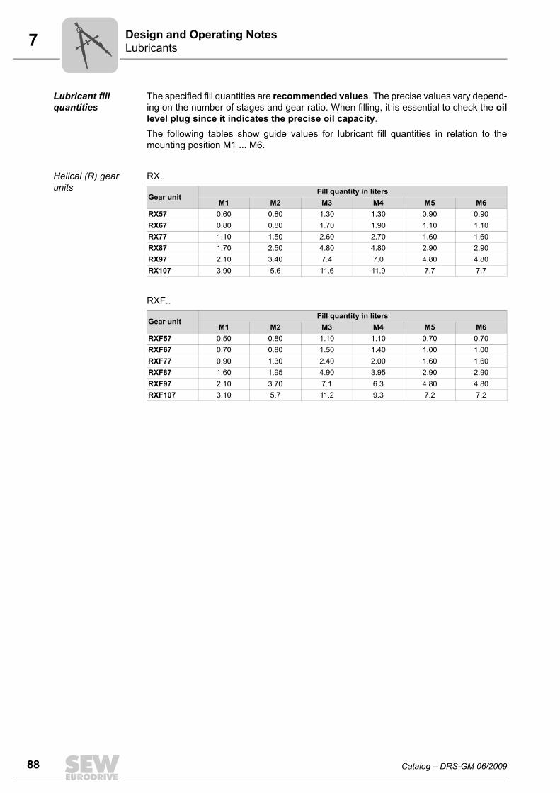
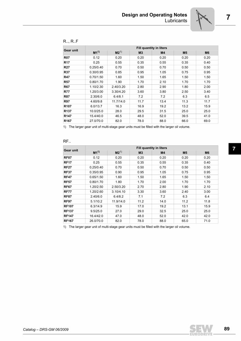
The specified fill quantities are recommended values. The precise values vary depend-ing on the number of stages and gear ratio. When filling, it is essential to check the oillevel plug since it indicates the precise oil capacity.The following tables show guide values for lubricant fill quantities in relation to themounting position M1 ... M6.
Helical (R) gear units
RX..
RXF..
Gear unitFill quantity in liters
M1 M2 M3 M4 M5 M6RX57 0.60 0.80 1.30 1.30 0.90 0.90RX67 0.80 0.80 1.70 1.90 1.10 1.10RX77 1.10 1.50 2.60 2.70 1.60 1.60RX87 1.70 2.50 4.80 4.80 2.90 2.90RX97 2.10 3.40 7.4 7.0 4.80 4.80RX107 3.90 5.6 11.6 11.9 7.7 7.7
Gear unitFill quantity in liters
M1 M2 M3 M4 M5 M6RXF57 0.50 0.80 1.10 1.10 0.70 0.70RXF67 0.70 0.80 1.50 1.40 1.00 1.00RXF77 0.90 1.30 2.40 2.00 1.60 1.60RXF87 1.60 1.95 4.90 3.95 2.90 2.90RXF97 2.10 3.70 7.1 6.3 4.80 4.80RXF107 3.10 5.7 11.2 9.3 7.2 7.2
Catalog – DRS-GM 06/2009 89
7LubricantsDesign and Operating Notes
7
R.., R..F
RF..
Gear unitFill quantity in liters
M11)
1) The larger gear unit of multi-stage gear units must be filled with the larger oil volume.
M21) M3 M4 M5 M6R07 0.12 0.20 0.20 0.20 0.20 0.20R17 0.25 0.55 0.35 0.55 0.35 0.40R27 0.25/0.40 0.70 0.50 0.70 0.50 0.50R37 0.30/0.95 0.85 0.95 1.05 0.75 0.95R47 0.70/1.50 1.60 1.50 1.65 1.50 1.50R57 0.80/1.70 1.90 1.70 2.10 1.70 1.70R67 1.10/2.30 2.40/3.20 2.80 2.90 1.80 2.00R77 1.20/3.00 3.30/4.20 3.60 3.80 2.50 3.40R87 2.30/6.0 6.4/8.1 7.2 7.2 6.3 6.5R97 4.60/9.8 11.7/14.0 11.7 13.4 11.3 11.7R107 6.0/13.7 16.3 16.9 19.2 13.2 15.9R137 10.0/25.0 28.0 29.5 31.5 25.0 25.0R147 15.4/40.0 46.5 48.0 52.0 39.5 41.0R167 27.0/70.0 82.0 78.0 88.0 66.0 69.0
Gear unitFill quantity in liters
M11)
1) The larger gear unit of multi-stage gear units must be filled with the larger oil volume.
M21) M3 M4 M5 M6RF07 0.12 0.20 0.20 0.20 0.20 0.20RF17 0.25 0.55 0.35 0.55 0.35 0.40RF27 0.25/0.40 0.70 0.50 0.70 0.50 0.50RF37 0.35/0.95 0.90 0.95 1.05 0.75 0.95RF47 0.65/1.50 1.60 1.50 1.65 1.50 1.50RF57 0.80/1.70 1.80 1.70 2.00 1.70 1.70RF67 1.20/2.50 2.50/3.20 2.70 2.80 1.90 2.10RF77 1.20/2.60 3.10/4.10 3.30 3.60 2.40 3.00RF87 2.40/6.0 6.4/8.2 7.1 7.2 6.3 6.4RF97 5.1/10.2 11.9/14.0 11.2 14.0 11.2 11.8RF107 6.3/14.9 15.9 17.0 19.2 13.1 15.9RF137 9.5/25.0 27.0 29.0 32.5 25.0 25.0RF147 16.4/42.0 47.0 48.0 52.0 42.0 42.0RF167 26.0/70.0 82.0 78.0 88.0 65.0 71.0
90 Catalog – DRS-GM 06/2009
7 LubricantsDesign and Operating Notes
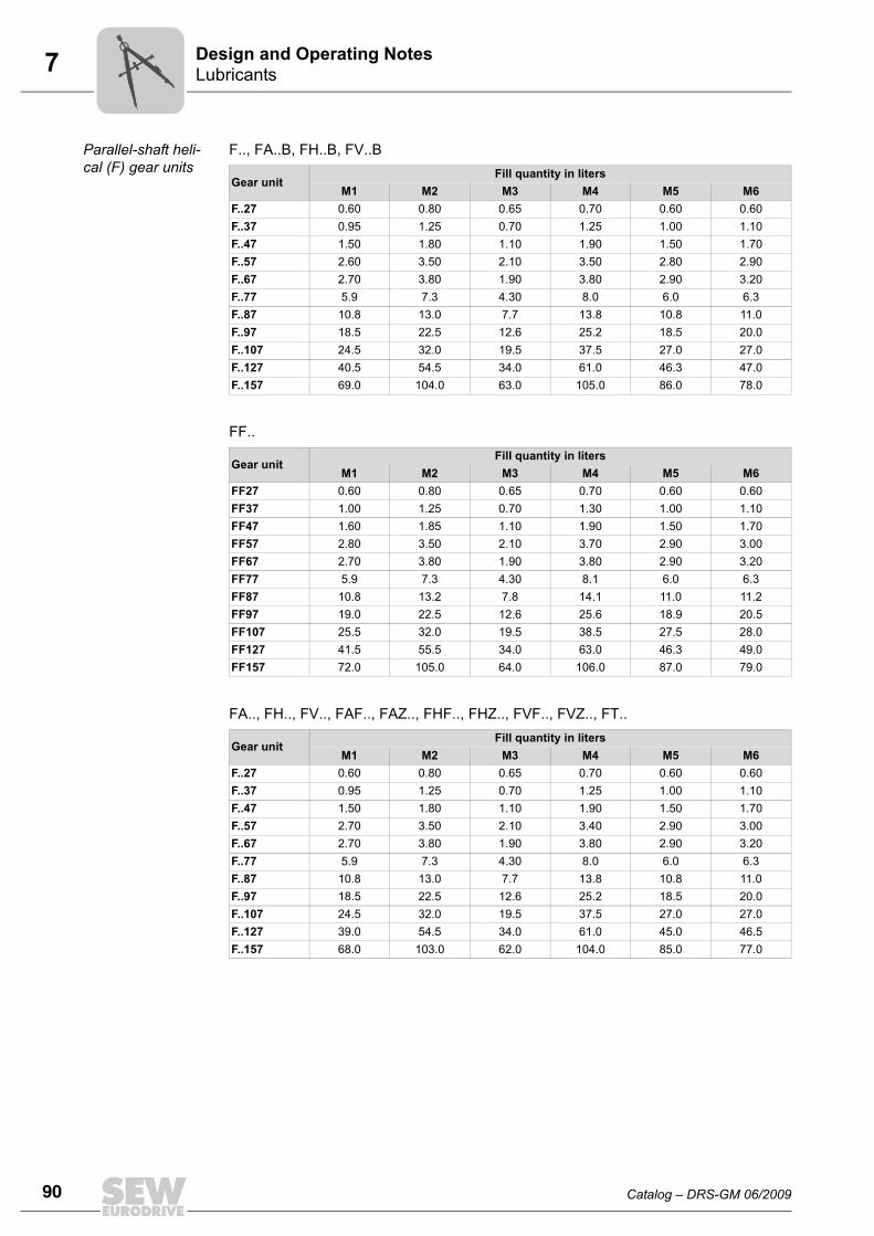
Parallel-shaft heli-cal (F) gear units
F.., FA..B, FH..B, FV..B
FF..
FA.., FH.., FV.., FAF.., FAZ.., FHF.., FHZ.., FVF.., FVZ.., FT..
Gear unitFill quantity in liters
M1 M2 M3 M4 M5 M6F..27 0.60 0.80 0.65 0.70 0.60 0.60F..37 0.95 1.25 0.70 1.25 1.00 1.10F..47 1.50 1.80 1.10 1.90 1.50 1.70F..57 2.60 3.50 2.10 3.50 2.80 2.90F..67 2.70 3.80 1.90 3.80 2.90 3.20F..77 5.9 7.3 4.30 8.0 6.0 6.3F..87 10.8 13.0 7.7 13.8 10.8 11.0F..97 18.5 22.5 12.6 25.2 18.5 20.0F..107 24.5 32.0 19.5 37.5 27.0 27.0F..127 40.5 54.5 34.0 61.0 46.3 47.0F..157 69.0 104.0 63.0 105.0 86.0 78.0
Gear unitFill quantity in liters
M1 M2 M3 M4 M5 M6FF27 0.60 0.80 0.65 0.70 0.60 0.60FF37 1.00 1.25 0.70 1.30 1.00 1.10FF47 1.60 1.85 1.10 1.90 1.50 1.70FF57 2.80 3.50 2.10 3.70 2.90 3.00FF67 2.70 3.80 1.90 3.80 2.90 3.20FF77 5.9 7.3 4.30 8.1 6.0 6.3FF87 10.8 13.2 7.8 14.1 11.0 11.2FF97 19.0 22.5 12.6 25.6 18.9 20.5FF107 25.5 32.0 19.5 38.5 27.5 28.0FF127 41.5 55.5 34.0 63.0 46.3 49.0FF157 72.0 105.0 64.0 106.0 87.0 79.0
Gear unitFill quantity in liters
M1 M2 M3 M4 M5 M6F..27 0.60 0.80 0.65 0.70 0.60 0.60F..37 0.95 1.25 0.70 1.25 1.00 1.10F..47 1.50 1.80 1.10 1.90 1.50 1.70F..57 2.70 3.50 2.10 3.40 2.90 3.00F..67 2.70 3.80 1.90 3.80 2.90 3.20F..77 5.9 7.3 4.30 8.0 6.0 6.3F..87 10.8 13.0 7.7 13.8 10.8 11.0F..97 18.5 22.5 12.6 25.2 18.5 20.0F..107 24.5 32.0 19.5 37.5 27.0 27.0F..127 39.0 54.5 34.0 61.0 45.0 46.5F..157 68.0 103.0 62.0 104.0 85.0 77.0
Catalog – DRS-GM 06/2009 91
7LubricantsDesign and Operating Notes
7
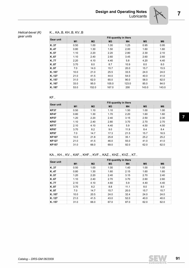
Helical-bevel (K) gear units
K.., KA..B, KH..B, KV..B
KF..
KA.., KH.., KV.., KAF.., KHF.., KVF.., KAZ.., KHZ.., KVZ.., KT..
Gear unitFill quantity in liters
M1 M2 M3 M4 M5 M6K..37 0.50 1.00 1.00 1.25 0.95 0.95K..47 0.80 1.30 1.50 2.00 1.60 1.60K..57 1.10 2.20 2.20 2.80 2.30 2.10K..67 1.10 2.40 2.60 3.45 2.60 2.60K..77 2.20 4.10 4.40 5.8 4.20 4.40K..87 3.70 8.0 8.7 10.9 8.0 8.0K..97 7.0 14.0 15.7 20.0 15.7 15.5K..107 10.0 21.0 25.5 33.5 24.0 24.0K..127 21.0 41.5 44.0 54.0 40.0 41.0K..157 31.0 62.0 65.0 90.0 58.0 62.0K..167 33.0 95.0 105.0 123.0 85.0 84.0K..187 53.0 152.0 167.0 200 143.0 143.0
Gear unitFill quantity in liters
M1 M2 M3 M4 M5 M6KF37 0.50 1.10 1.10 1.50 1.00 1.00KF47 0.80 1.30 1.70 2.20 1.60 1.60KF57 1.20 2.20 2.40 3.15 2.50 2.30KF67 1.10 2.40 2.80 3.70 2.70 2.70KF77 2.10 4.10 4.40 5.9 4.50 4.50KF87 3.70 8.2 9.0 11.9 8.4 8.4KF97 7.0 14.7 17.3 21.5 15.7 16.5KF107 10.0 21.8 25.8 35.1 25.2 25.2KF127 21.0 41.5 46.0 55.0 41.0 41.0KF157 31.0 66.0 69.0 92.0 62.0 62.0
Gear unitFill quantity in liters
M1 M2 M3 M4 M5 M6K..37 0.50 1.00 1.00 1.40 1.00 1.00K..47 0.80 1.30 1.60 2.15 1.60 1.60K..57 1.20 2.20 2.40 3.15 2.70 2.40K..67 1.10 2.40 2.70 3.70 2.60 2.60K..77 2.10 4.10 4.60 5.9 4.40 4.40K..87 3.70 8.2 8.8 11.1 8.0 8.0K..97 7.0 14.7 15.7 20.0 15.7 15.7K..107 10.0 20.5 24.0 32.4 24.0 24.0K..127 21.0 41.5 43.0 52.0 40.0 40.0K..157 31.0 66.0 67.0 87.0 62.0 62.0
92 Catalog – DRS-GM 06/2009
7 LubricantsDesign and Operating Notes
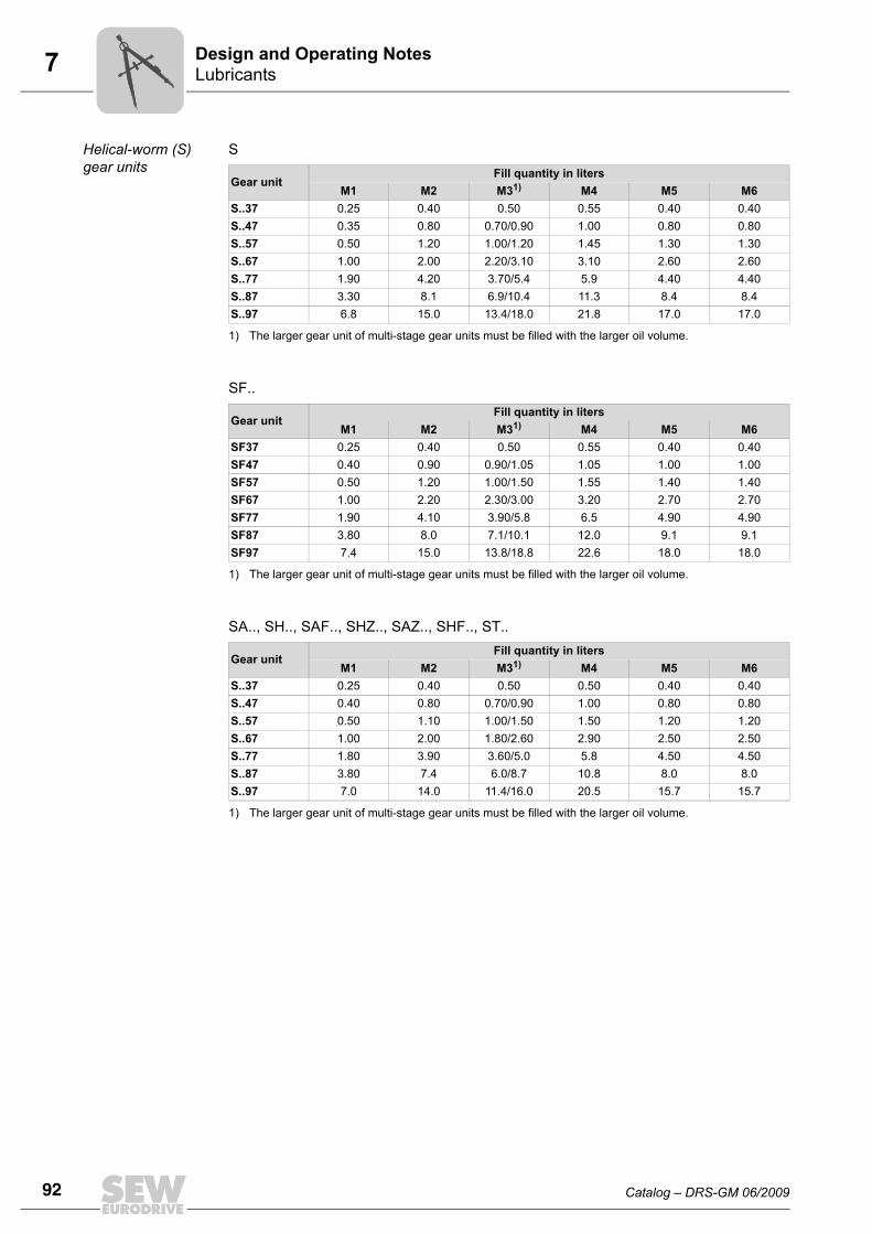
Helical-worm (S) gear units
S
SF..
SA.., SH.., SAF.., SHZ.., SAZ.., SHF.., ST..
Gear unitFill quantity in liters
M1 M2 M31)
1) The larger gear unit of multi-stage gear units must be filled with the larger oil volume.
M4 M5 M6S..37 0.25 0.40 0.50 0.55 0.40 0.40S..47 0.35 0.80 0.70/0.90 1.00 0.80 0.80S..57 0.50 1.20 1.00/1.20 1.45 1.30 1.30S..67 1.00 2.00 2.20/3.10 3.10 2.60 2.60S..77 1.90 4.20 3.70/5.4 5.9 4.40 4.40S..87 3.30 8.1 6.9/10.4 11.3 8.4 8.4S..97 6.8 15.0 13.4/18.0 21.8 17.0 17.0
Gear unitFill quantity in liters
M1 M2 M31)
1) The larger gear unit of multi-stage gear units must be filled with the larger oil volume.
M4 M5 M6SF37 0.25 0.40 0.50 0.55 0.40 0.40SF47 0.40 0.90 0.90/1.05 1.05 1.00 1.00SF57 0.50 1.20 1.00/1.50 1.55 1.40 1.40SF67 1.00 2.20 2.30/3.00 3.20 2.70 2.70SF77 1.90 4.10 3.90/5.8 6.5 4.90 4.90SF87 3.80 8.0 7.1/10.1 12.0 9.1 9.1SF97 7.4 15.0 13.8/18.8 22.6 18.0 18.0
Gear unitFill quantity in liters
M1 M2 M31)
1) The larger gear unit of multi-stage gear units must be filled with the larger oil volume.
M4 M5 M6S..37 0.25 0.40 0.50 0.50 0.40 0.40S..47 0.40 0.80 0.70/0.90 1.00 0.80 0.80S..57 0.50 1.10 1.00/1.50 1.50 1.20 1.20S..67 1.00 2.00 1.80/2.60 2.90 2.50 2.50S..77 1.80 3.90 3.60/5.0 5.8 4.50 4.50S..87 3.80 7.4 6.0/8.7 10.8 8.0 8.0S..97 7.0 14.0 11.4/16.0 20.5 15.7 15.7
Catalog – DRS-GM 06/2009 93
7LubricantsDesign and Operating Notes
7
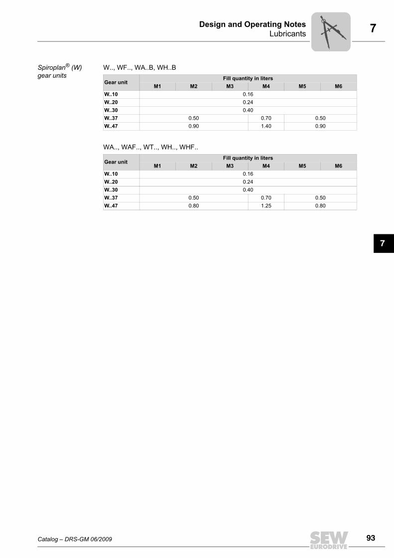
Spiroplan® (W) gear units
W.., WF.., WA..B, WH..B
WA.., WAF.., WT.., WH.., WHF..
Gear unitFill quantity in liters
M1 M2 M3 M4 M5 M6W..10 0.16W..20 0.24W..30 0.40W..37 0.50 0.70 0.50W..47 0.90 1.40 0.90
Gear unitFill quantity in liters
M1 M2 M3 M4 M5 M6W..10 0.16W..20 0.24W..30 0.40W..37 0.50 0.70 0.50W..47 0.80 1.25 0.80
94 Catalog – DRS-GM 06/2009
7 Reduced backlash gear unitsDesign and Operating Notes
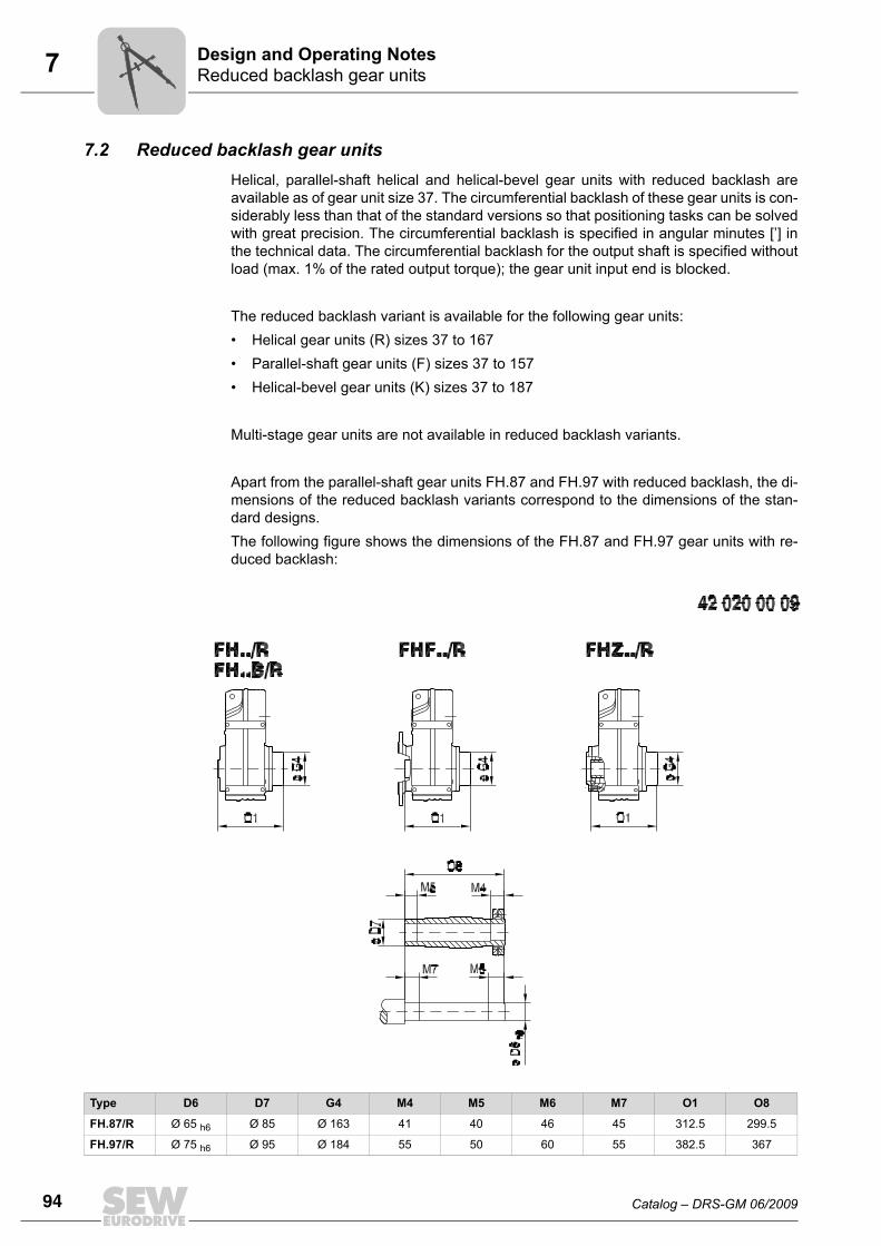
7.2 Reduced backlash gear unitsHelical, parallel-shaft helical and helical-bevel gear units with reduced backlash areavailable as of gear unit size 37. The circumferential backlash of these gear units is con-siderably less than that of the standard versions so that positioning tasks can be solvedwith great precision. The circumferential backlash is specified in angular minutes [’] inthe technical data. The circumferential backlash for the output shaft is specified withoutload (max. 1% of the rated output torque); the gear unit input end is blocked.
The reduced backlash variant is available for the following gear units:• Helical gear units (R) sizes 37 to 167• Parallel-shaft gear units (F) sizes 37 to 157• Helical-bevel gear units (K) sizes 37 to 187
Multi-stage gear units are not available in reduced backlash variants.
Apart from the parallel-shaft gear units FH.87 and FH.97 with reduced backlash, the di-mensions of the reduced backlash variants correspond to the dimensions of the stan-dard designs.The following figure shows the dimensions of the FH.87 and FH.97 gear units with re-duced backlash:
Type D6 D7 G4 M4 M5 M6 M7 O1 O8
FH.87/R Ø 65 h6 Ø 85 Ø 163 41 40 46 45 312.5 299.5
FH.97/R Ø 75 h6 Ø 95 Ø 184 55 50 60 55 382.5 367
Catalog – DRS-GM 06/2009 95
7Installation/removal of gear units with hollow shafts and keysDesign and Operating Notes
7
7.3 Installation/removal of gear units with hollow shafts and keys
Assembly SEW-EURODRIVE recommends two variants for mounting gear units with hollow shaftand key onto the input shaft of the driven machine (= customer shaft):1. Use the provided fastening parts for installation.2. Use the optional installation/removal kit for installation.
1. Provided fasten-ing parts
The following fastening parts are supplied as standard:• Retaining screw with washer (2)• Retaining ring (3)
Note the following points concerning the customer shaft:• The installation length of the customer shaft with contact shoulder (A) must be L8 -
1 mm.• The installation length of the customer shaft without contact shoulder (B) must equal
L8.
• Always use the supplied NOCO® Fluid for assembly. The fluid prevents contact cor-rosion and facilitates subsequent disassembly.
• The keyway dimension X is specified by the customers, but X must be > DK.
96 Catalog – DRS-GM 06/2009
7 Installation/removal of gear units with hollow shafts and keysDesign and Operating Notes
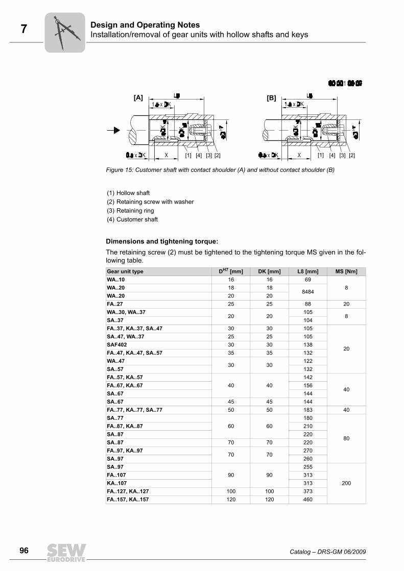
Dimensions and tightening torque:The retaining screw (2) must be tightened to the tightening torque MS given in the fol-lowing table.
Figure 15: Customer shaft with contact shoulder (A) and without contact shoulder (B)
(1) Hollow shaft(2) Retaining screw with washer(3) Retaining ring(4) Customer shaft
Gear unit type DH7 [mm] DK [mm] L8 [mm] MS [Nm]WA..10 16 16 69
8WA..20 18 188484
WA..20 20 20FA..27 25 25 88 20WA..30, WA..37
20 20105
8SA..37 104FA..37, KA..37, SA..47 30 30 105
20
SA..47, WA..37 25 25 105SAF402 30 30 138FA..47, KA..47, SA..57 35 35 132WA..47
30 30122
SA..57 132FA..57, KA..57
40 40142
40FA..67, KA..67 156SA..67 144SA..67 45 45 144FA..77, KA..77, SA..77 50 50 183 40SA..77
60 60180
80
FA..87, KA..87 210SA..87 220SA..87 70 70 220FA..97, KA..97
70 70270
SA..97 260SA..97
90 90255
200FA..107 313KA..107 313FA..127, KA..127 100 100 373FA..157, KA..157 120 120 460
[1] [2][3][4] [1] [4] [3] [2]
[A] [B]
Catalog – DRS-GM 06/2009 97
7Installation/removal of gear units with hollow shafts and keysDesign and Operating Notes
7
2. Installa-tion/removal kit
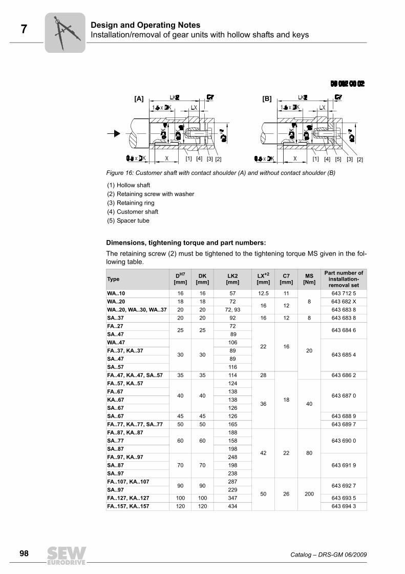
You can also use the optional installation/removal kit for installation. You can order thekit for the specific gear unit type(s) by quoting the part numbers in the table below. Thedelivery includes:• Spacer tube for installation without contact shoulder (5)• Retaining screw for installation (2)• Forcing washer for removal (7)• Locked nut for removal (8)The short retaining screw delivered as standard is not required.
Note the following points concerning the customer shaft:• The installation length of the customer shaft must be LK2. Do not use the spacer if
the customer shaft has a contact shoulder (A).• The installation length of the customer shaft must be LK2. Use the spacer if the cus-
tomer shaft has a contact shoulder (B).
98 Catalog – DRS-GM 06/2009
7 Installation/removal of gear units with hollow shafts and keysDesign and Operating Notes
Dimensions, tightening torque and part numbers:The retaining screw (2) must be tightened to the tightening torque MS given in the fol-lowing table.
Figure 16: Customer shaft with contact shoulder (A) and without contact shoulder (B)
(1) Hollow shaft(2) Retaining screw with washer(3) Retaining ring(4) Customer shaft(5) Spacer tube
Type DH7
[mm]DK
[mm]LK2
[mm]LX+2
[mm]C7
[mm]MS
[Nm]Part number of
installation-removal set
WA..10 16 16 57 12.5 118
643 712 5WA..20 18 18 72
16 12643 682 X
WA..20, WA..30, WA..37 20 20 72, 93 643 683 8SA..37 20 20 92 16 12 8 643 683 8FA..27
25 2572
22 1620
643 684 6SA..47 89WA..47
30 30
106
643 685 4FA..37, KA..37 89SA..47 89SA..57 116FA..47, KA..47, SA..57 35 35 114 28
18
643 686 2FA..57, KA..57
40 40
124
36 40643 687 0
FA..67 138KA..67 138SA..67 126SA..67 45 45 126 643 688 9FA..77, KA..77, SA..77 50 50 165 643 689 7FA..87, KA..87
60 60188
42 22 80
643 690 0SA..77 158SA..87 198FA..97, KA..97
70 70248
643 691 9SA..87 198SA..97 238FA..107, KA..107
90 90287
50 26 200643 692 7
SA..97 229FA..127, KA..127 100 100 347 643 693 5FA..157, KA..157 120 120 434 643 694 3
[1] [2][3][4] [1] [4] [3] [2][5]
[A] [B]
Catalog – DRS-GM 06/2009 99
7Installation/removal of gear units with hollow shafts and keysDesign and Operating Notes
7
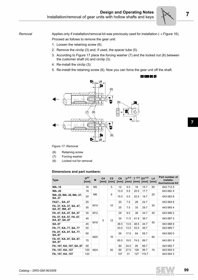
Removal Applies only if installation/removal kit was previously used for installation (→ Figure 16).Proceed as follows to remove the gear unit:1. Loosen the retaining screw (6).2. Remove the circlip (3) and, if used, the spacer tube (5).3. According to Figure 17 place the forcing washer (7) and the locked nut (8) between
the customer shaft (4) and circlip (3).4. Re-install the circlip (3).5. Re-install the retaining screw (6). Now you can force the gear unit off the shaft.
Dimensions and part numbers:
Figure 17: Removal
(6) Retaining screw(7) Forcing washer(8) Locked nut for removal
Type DH7
[mm] M C4[mm]
C5[mm]
C6[mm]
U-0.5
[mm]T -0.5
[mm]D3-0.5
[mm]L4
[mm]Part number of
installa-tion/removal kit
WA..10 16 M5
5
5 12 4.5 18 15.7 50 643 712 5WA..20 18
M6 613.5 5.5 20.5 17.7
25643 682 X
WA..20, WA..30, WA..37, SA..37 20 15.5 5.5 22.5 19.7 643 683 8
FA27.., SA..47 25M10 10
20 7.5 28 24.735
643 684 6FA..37, KA..37, SA..47, SA..57, WA..47 30 25 7.5 33 29.7 643 685 4
FA..47, KA..47, SA..57 35 M12
12
29 9.5 38 34.7 45 643 686 2FA..57, KA..57, FA..67, KA..67, SA..67 40
M1634 11.5 41.9 39.7
50643 687 0
SA..67 45 38.5 13.5 48.5 44.7 643 688 9FA..77, KA..77, SA..77 50 43.5 13.5 53.5 49.7 643 689 7FA..87, KA..87, SA..77, SA..87 60
M20 1656 17.5 64 59.7
60643 690 0
FA..97, KA..97, SA..87, SA..97 70 65.5 19.5 74.5 69.7 643 691 9
FA..107, KA..107, SA..97 90M24 20
80 24.5 95 89.770
643 692 7FA..127, KA..127 100 89 27.5 106 99.7 643 693 5FA..157, KA..157 120 107 31 127 119.7 643 694 3
[6]
[6]
[7] [8]
[8]
100 Catalog – DRS-GM 06/2009
7 Gear units with hollow shaftDesign and Operating Notes
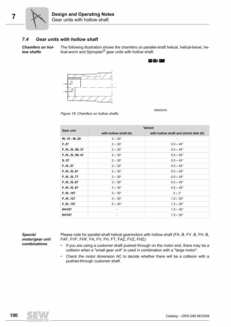
7.4 Gear units with hollow shaftChamfers on hol-low shafts
The following illustration shows the chamfers on parallel-shaft helical, helical-bevel, he-lical-worm and Spiroplan® gear units with hollow shaft:
Special motor/gear unit combinations
Please note for parallel-shaft helical gearmotors with hollow shaft (FA..B, FV..B, FH..B,FAF, FVF, FHF, FA, FV, FH, FT, FAZ, FVZ, FHZ):• If you are using a customer shaft pushed through on the motor end, there may be a
collision when a "small gear unit" is used in combination with a "large motor".• Check the motor dimension AC to decide whether there will be a collision with a
pushed-through customer shaft.
59845AXXFigure 18: Chamfers on hollow shafts
Gear unitVariant
with hollow shaft (A) with hollow shaft and shrink disk (H)
W..10 - W..30 2 × 30° -
F..27 2 × 30° 0.5 × 45°
F../K../S../W..37 2 × 30° 0.5 × 45°
F../K../S../W..47 2 × 30° 0.5 × 45°
S..57 2 × 30° 0.5 × 45°
F../K..57 2 × 30° 0.5 × 45°
F../K../S..67 2 × 30° 0.5 × 45°
F../K../S..77 2 × 30° 0.5 × 45°
F../K../S..87 3 × 30° 0.5 × 45°
F../K../S..97 3 × 30° 0.5 × 45°
F../K..107 3 × 30° 3 × 2°
F../K..127 5 × 30° 1.5 × 30°
F../K..157 5 × 30° 1.5 × 30°
KH167 - 1.5 × 30°
KH187 - 1.5 × 30°
Catalog – DRS-GM 06/2009 101
7TorqLOC® mounting system for gear units with hollow shaftDesign and Operating Notes
7
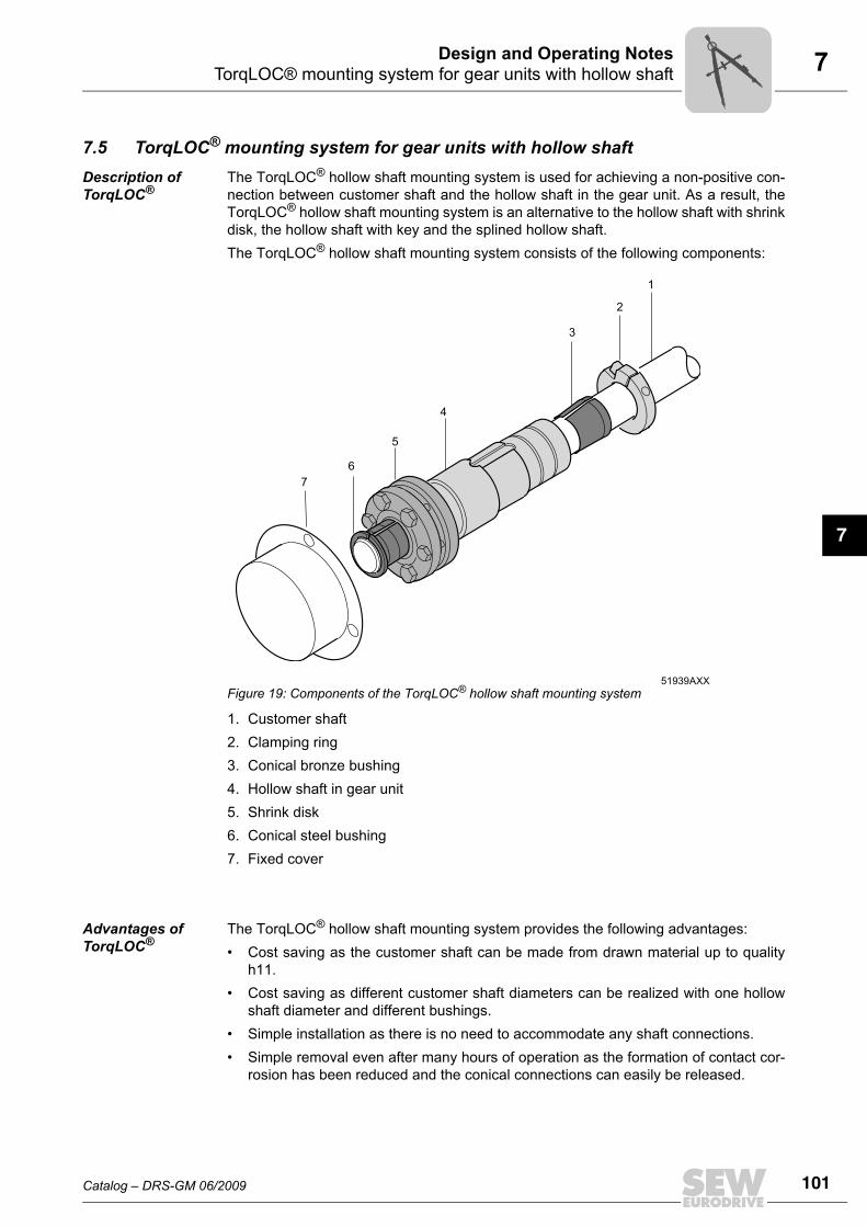
7.5 TorqLOC® mounting system for gear units with hollow shaftDescription of TorqLOC®
The TorqLOC® hollow shaft mounting system is used for achieving a non-positive con-nection between customer shaft and the hollow shaft in the gear unit. As a result, theTorqLOC® hollow shaft mounting system is an alternative to the hollow shaft with shrinkdisk, the hollow shaft with key and the splined hollow shaft.The TorqLOC® hollow shaft mounting system consists of the following components:
1. Customer shaft2. Clamping ring3. Conical bronze bushing4. Hollow shaft in gear unit5. Shrink disk6. Conical steel bushing7. Fixed cover
Advantages of TorqLOC®
The TorqLOC® hollow shaft mounting system provides the following advantages:• Cost saving as the customer shaft can be made from drawn material up to quality
h11.• Cost saving as different customer shaft diameters can be realized with one hollow
shaft diameter and different bushings.• Simple installation as there is no need to accommodate any shaft connections.• Simple removal even after many hours of operation as the formation of contact cor-
rosion has been reduced and the conical connections can easily be released.
51939AXXFigure 19: Components of the TorqLOC® hollow shaft mounting system
6
5
4
3
2
1
7
102 Catalog – DRS-GM 06/2009
7 TorqLOC® mounting system for gear units with hollow shaftDesign and Operating Notes
Technical data The TorqLOC® hollow shaft mounting system is approved for input torques of 92 Nm to18000 Nm.The following gear units are available with TorqLOC® hollow shaft mounting system:• Parallel-shaft helical gear units in gear unit sizes 37 to 157 (FT37 to FT157)• Helical-bevel gear units in gear unit sizes 37 to 157 (KT37 to KT157)• Helical-worm gear units in gear unit sizes 37 to 97 (ST37 to ST97)• Spiroplan® gear unit sizes 37 and 47 (WT37 and WT47)
Available options The following options are available for gear units with a TorqLOC® hollow shaft mount-ing system:• Helical-bevel, helical-worm and Spiroplan® gear units with TorqLOC® (KT.., ST..,
WT37, WT47): The "torque arm" (../T) option is available.• Parallel-shaft helical gear units with TorqLOC® (FT..): The "rubber buffer" (../G) op-
tion is available.
Catalog – DRS-GM 06/2009 103
7Shouldered hollow shaft with shrink disk optionDesign and Operating Notes
7
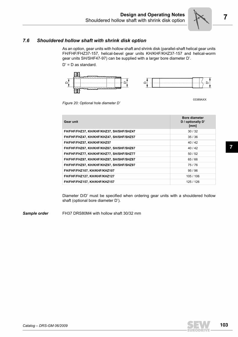
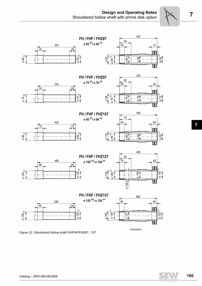
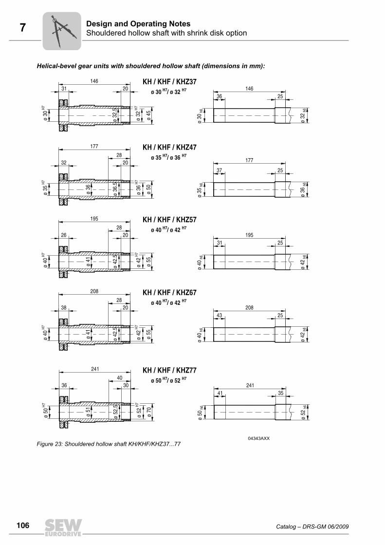
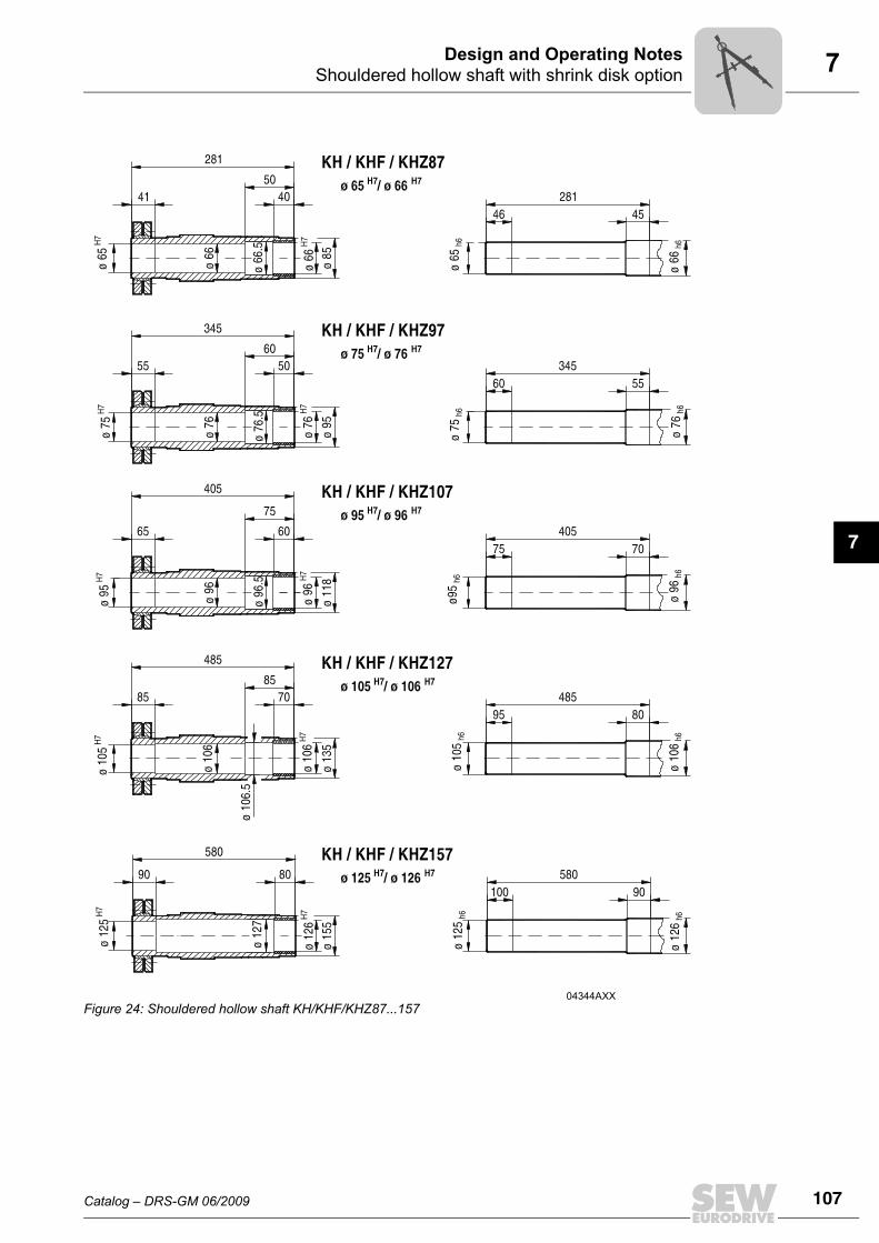
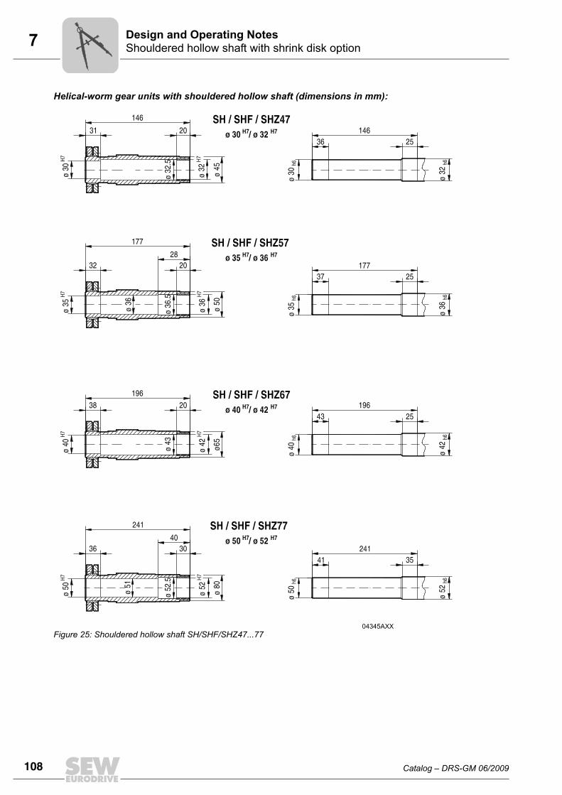
7.6 Shouldered hollow shaft with shrink disk optionAs an option, gear units with hollow shaft and shrink disk (parallel-shaft helical gear unitsFH/FHF/FHZ37-157, helical-bevel gear units KH/KHF/KHZ37-157 and helical-wormgear units SH/SHF47-97) can be supplied with a larger bore diameter D’.D’ = D as standard.
Diameter D/D’ must be specified when ordering gear units with a shouldered hollowshaft (optional bore diameter D’).
Sample order FH37 DRS80M4 with hollow shaft 30/32 mm
03389AXXFigure 20: Optional hole diameter D’
Gear unitBore diameter
D / optionally D’[mm]
FH/FHF/FHZ37, KH/KHF/KHZ37, SH/SHF/SHZ47 30 / 32
FH/FHF/FHZ47, KH/KHF/KHZ47, SH/SHF/SHZ57 35 / 36
FH/FHF/FHZ57, KH/KHF/KHZ57 40 / 42
FH/FHF/FHZ67, KH/KHF/KHZ67, SH/SHF/SHZ67 40 / 42
FH/FHF/FHZ77, KH/KHF/KHZ77, SH/SHF/SHZ77 50 / 52
FH/FHF/FHZ87, KH/KHF/KHZ87, SH/SHF/SHZ87 65 / 66
FH/FHF/FHZ97, KH/KHF/KHZ97, SH/SHF/SHZ97 75 / 76
FH/FHF/FHZ107, KH/KHF/KHZ107 95 / 96
FH/FHF/FHZ127, KH/KHF/KHZ127 105 / 106
FH/FHF/FHZ157, KH/KHF/KHZ157 125 / 126
D D'
D D'
104 Catalog – DRS-GM 06/2009
7 Shouldered hollow shaft with shrink disk optionDesign and Operating Notes
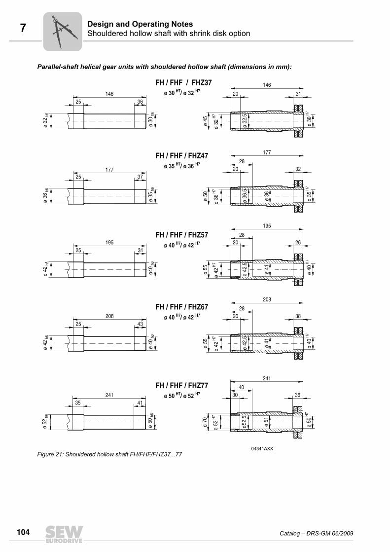
Parallel-shaft helical gear units with shouldered hollow shaft (dimensions in mm):
04341AXXFigure 21: Shouldered hollow shaft FH/FHF/FHZ37...77
Catalog – DRS-GM 06/2009 105
7Shouldered hollow shaft with shrink disk optionDesign and Operating Notes
7
04342AXXFigure 22: Shouldered hollow shaft FH/FHF/FHZ87...157
106 Catalog – DRS-GM 06/2009
7 Shouldered hollow shaft with shrink disk optionDesign and Operating Notes
Helical-bevel gear units with shouldered hollow shaft (dimensions in mm):
04343AXXFigure 23: Shouldered hollow shaft KH/KHF/KHZ37...77
Catalog – DRS-GM 06/2009 107
7Shouldered hollow shaft with shrink disk optionDesign and Operating Notes
7
04344AXXFigure 24: Shouldered hollow shaft KH/KHF/KHZ87...157
108 Catalog – DRS-GM 06/2009
7 Shouldered hollow shaft with shrink disk optionDesign and Operating Notes
Helical-worm gear units with shouldered hollow shaft (dimensions in mm):
04345AXXFigure 25: Shouldered hollow shaft SH/SHF/SHZ47...77
Catalog – DRS-GM 06/2009 109
7Shouldered hollow shaft with shrink disk optionDesign and Operating Notes
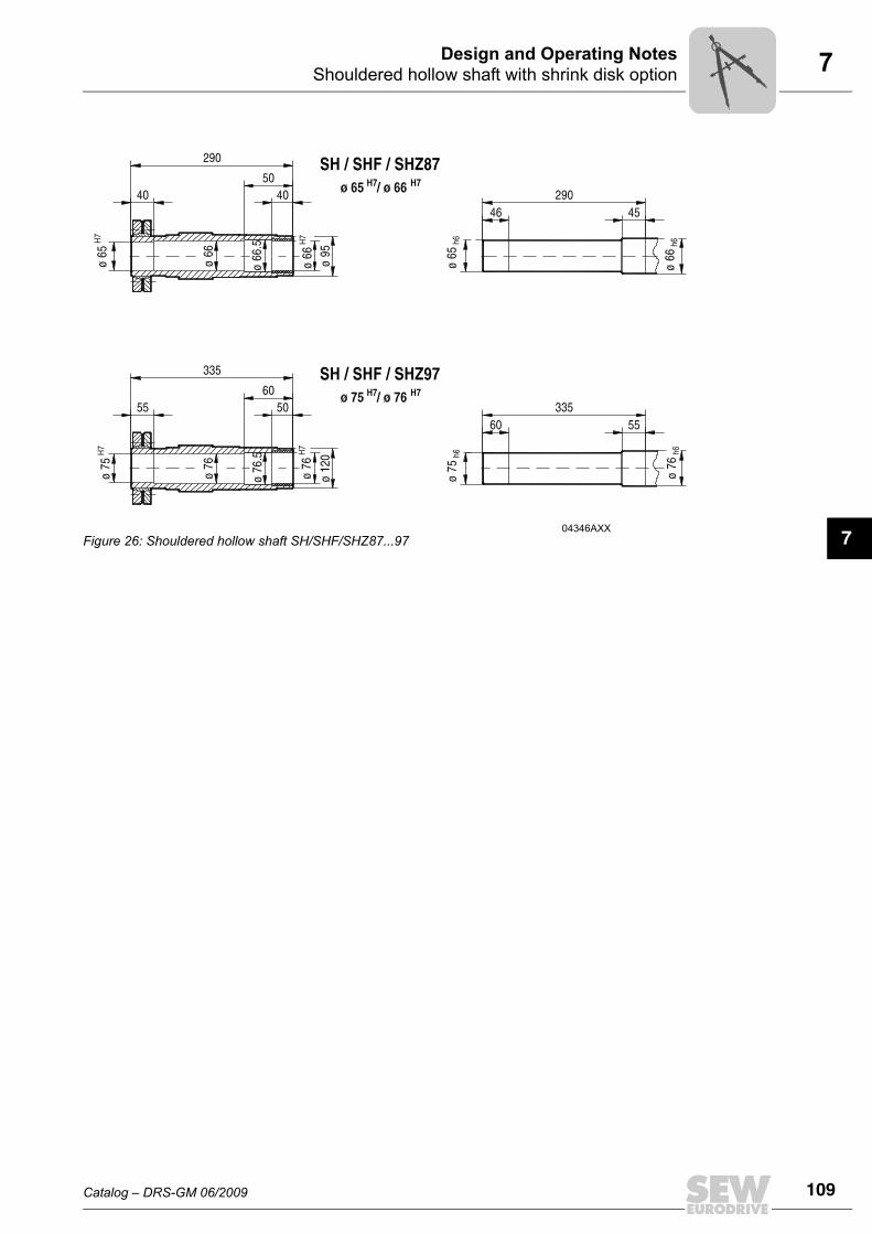
704346AXX
Figure 26: Shouldered hollow shaft SH/SHF/SHZ87...97
110 Catalog – DRS-GM 06/2009
7 Adapters for mounting IEC motorsDesign and Operating Notes
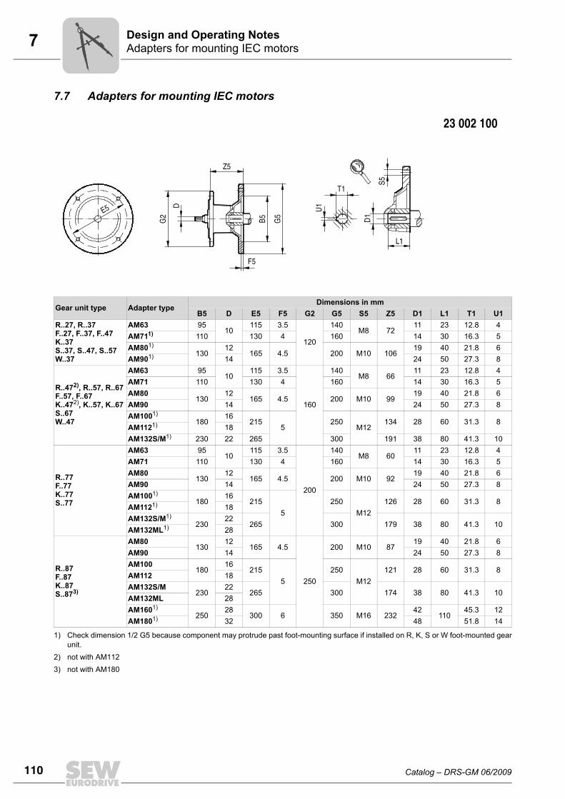
7.7 Adapters for mounting IEC motors
Gear unit type Adapter typeDimensions in mm
B5 D E5 F5 G2 G5 S5 Z5 D1 L1 T1 U1R..27, R..37F..27, F..37, F..47K..37S..37, S..47, S..57W..37
AM63 9510
115 3.5
120
140M8 72
11 23 12.8 4AM711) 110 130 4 160 14 30 16.3 5AM801)
13012
165 4.5 200 M10 10619 40 21.8 6
AM901) 14 24 50 27.3 8
R..472), R..57, R..67F..57, F..67K..472), K..57, K..67S..67W..47
AM63 9510
115 3.5
160
140M8 66
11 23 12.8 4AM71 110 130 4 160 14 30 16.3 5AM80
13012
165 4.5 200 M10 9919 40 21.8 6
AM90 14 24 50 27.3 8AM1001)
18016
2155
250M12
134 28 60 31.3 8AM1121) 18AM132S/M1) 230 22 265 300 191 38 80 41.3 10
R..77F..77K..77S..77
AM63 9510
115 3.5
200
140M8 60
11 23 12.8 4AM71 110 130 4 160 14 30 16.3 5AM80
13012
165 4.5 200 M10 9219 40 21.8 6
AM90 14 24 50 27.3 8AM1001)
18016
2155
250M12
126 28 60 31.3 8AM1121) 18AM132S/M1)
23022
265 300 179 38 80 41.3 10AM132ML1) 28
R..87F..87K..87S..873)
AM80130
12165 4.5
250
200 M10 8719 40 21.8 6
AM90 14 24 50 27.3 8AM100
18016
2155
250M12
121 28 60 31.3 8AM112 18AM132S/M
23022
265 300 174 38 80 41.3 10AM132ML 28AM1601)
25028
300 6 350 M16 23242
11045.3 12
AM1801) 32 48 51.8 14
1) Check dimension 1/2 G5 because component may protrude past foot-mounting surface if installed on R, K, S or W foot-mounted gearunit.
2) not with AM1123) not with AM180
Catalog – DRS-GM 06/2009 111
7Adapters for mounting IEC motorsDesign and Operating Notes
7
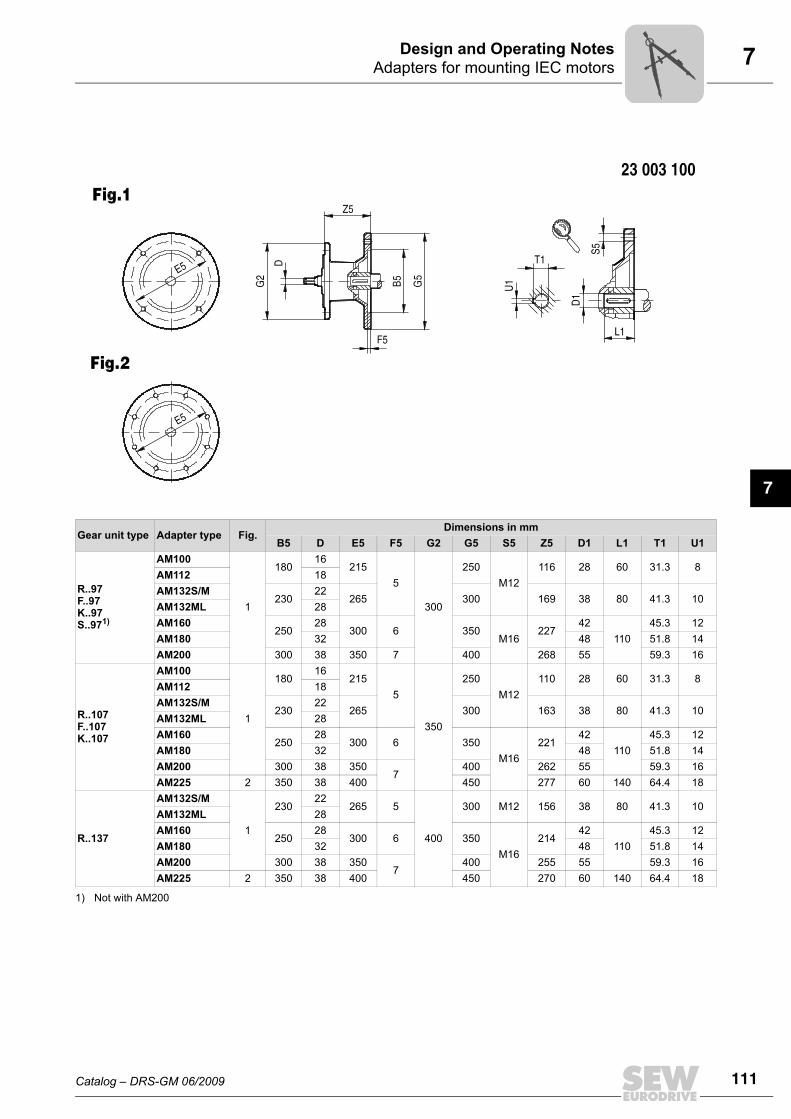
Gear unit type Adapter type Fig.Dimensions in mm
B5 D E5 F5 G2 G5 S5 Z5 D1 L1 T1 U1
R..97F..97K..97S..971)
AM100
1
18016
2155
300
250M12
116 28 60 31.3 8AM112 18AM132S/M
23022
265 300 169 38 80 41.3 10AM132ML 28AM160
25028
300 6 350M16
22742
11045.3 12
AM180 32 48 51.8 14AM200 300 38 350 7 400 268 55 59.3 16
R..107F..107K..107
AM100
1
18016
2155
350
250M12
110 28 60 31.3 8AM112 18AM132S/M
23022
265 300 163 38 80 41.3 10AM132ML 28AM160
25028
300 6 350M16
22142
11045.3 12
AM180 32 48 51.8 14AM200 300 38 350
7400 262 55 59.3 16
AM225 2 350 38 400 450 277 60 140 64.4 18
R..137
AM132S/M
1
23022
265 5
400
300 M12 156 38 80 41.3 10AM132ML 28AM160
25028
300 6 350M16
21442
11045.3 12
AM180 32 48 51.8 14AM200 300 38 350
7400 255 55 59.3 16
AM225 2 350 38 400 450 270 60 140 64.4 18
1) Not with AM200
112 Catalog – DRS-GM 06/2009
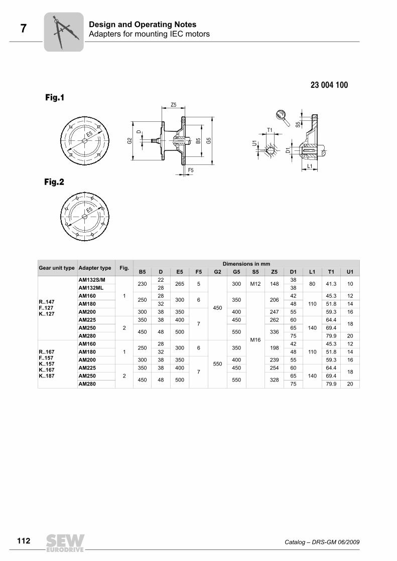
7 Adapters for mounting IEC motorsDesign and Operating Notes
Gear unit type Adapter type Fig.Dimensions in mm
B5 D E5 F5 G2 G5 S5 Z5 D1 L1 T1 U1
R..147F..127K..127
AM132S/M
1
23022
265 5
450
300 M12 14838
80 41.3 10AM132ML 28 38AM160
25028
300 6 350
M16
20642
11045.3 12
AM180 32 48 51.8 14AM200 300 38 350
7
400 247 55 59.3 16AM225
2350 38 400 450 262 60
14064.4
18AM250
450 48 500 550 33665 69.4
AM280 75 79.9 20
R..167F..157K..157K..167K..187
AM1601
25028
300 6
550
350 19842
11045.3 12
AM180 32 48 51.8 14AM200 300 38 350
7
400 239 55 59.3 16AM225
2350 38 400 450 254 60
14064.4
18AM250
450 48 500 550 32865 69.4
AM280 75 79.9 20
Catalog – DRS-GM 06/2009 113
7Adapters for mounting NEMA motorsDesign and Operating Notes
7
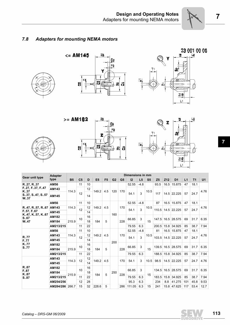
7.8 Adapters for mounting NEMA motors
Gear unit type Adapter type
Dimensions in mmB5 C5 D E5 F5 G2 G5 l2 L5 S5 Z5 Z12 D1 L1 T1 U1
R..27, R..37F..27, F..37, F..47K..37S..37, S..47, S..57W..37
AM56
114.3
11 10
149.2 4.5 120 170
52.55 -4.8
10.5
93.5 16.5 15.875 47 18.1
4.76AM143
1212
54.1 3 117 14.5 22.225 57 24.7AM145 14
R..47, R..57, R..67F..57, F..67K..47, K..57, K..67S..67W..47
AM56114.3
11 10149.2 4.5
160
17052.55 -4.8
10.587 16.5 15.875 47 18.1
4.76AM14312
1254.1 3 110.5 14.5 22.225 57 24.7
AM145 14AM182
215.910
16184 5 228
66.85 315
147.5 16.5 28.575 69 31.7 6.35AM184 18AM213/215 11 22 79.55 6.3 200.5 15.8 34.925 85 38.7 7.94
R..77F..77K..77S..77
AM56114.3
11 10149.2 4.5
200
17052.55 -4.8
10.581 16.5 15.875 47 18.1
4.76AM14312
1254.1 3 103.5 14.5 22.225 57 24.7
AM145 14AM182
215.910
16184 5 228
66.85 315
139.5 16.5 28.575 69 31.7 6.35AM184 18AM213/215 11 22 79.55 6.3 188.5 15.8 34.925 85 38.7 7.94
R..87F..87K..87S..87
AM143114.3 12
12149.2 4.5
250
170 54.1 3 10.5 98.5 14.5 22.225 57 24.7 4.76AM145 14AM182
215.910
16
184 5 22866.85 3
15134.5 16.5 28.575 69 31.7 6.35
AM184 18AM213/215 11 22 79.55 6.3 183.5 15.8 34.925 85 38.7 7.94AM254/256 12 28 95.3 6.3 234 8.8 41.275 101 45.8 9.53AM284/286 266.7 15 32 228.6 5 286 111.05 6.3 15 241 15.8 47.625 117 53.4 12.7
114 Catalog – DRS-GM 06/2009
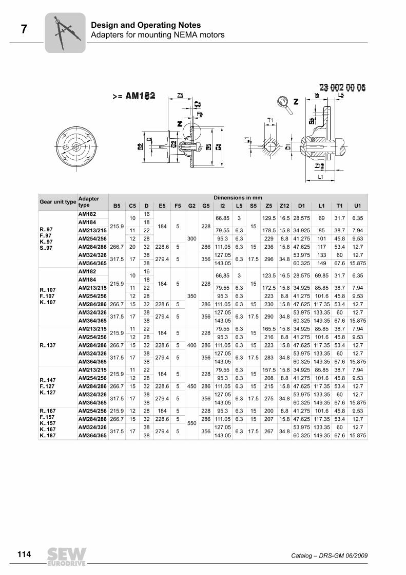
7 Adapters for mounting NEMA motorsDesign and Operating Notes
Gear unit type Adapter type
Dimensions in mmB5 C5 D E5 F5 G2 G5 I2 L5 S5 Z5 Z12 D1 L1 T1 U1
R..97F..97K..97S..97
AM182
215.910
16
184 5
300
22866.85 3
15129.5 16.5 28.575 69 31.7 6.35
AM184 18AM213/215 11 22 79.55 6.3 178.5 15.8 34.925 85 38.7 7.94AM254/256 12 28 95.3 6.3 229 8.8 41.275 101 45.8 9.53AM284/286 266.7 20 32 228.6 5 286 111.05 6.3 15 236 15.8 47.625 117 53.4 12.7AM324/326
317.5 1738
279.4 5 356127.05
6.3 17.5 296 34.853.975 133 60 12.7
AM364/365 38 143.05 60.325 149 67.6 15.875
R..107F..107K..107
AM182
215.910
16
184 5
350
22866,85 3
15123.5 16.5 28.575 69.85 31.7 6.35
AM184 18AM213/215 11 22 79.55 6.3 172.5 15.8 34.925 85.85 38.7 7.94AM254/256 12 28 95.3 6.3 223 8.8 41.275 101.6 45.8 9.53AM284/286 266.7 15 32 228.6 5 286 111.05 6.3 15 230 15.8 47.625 117.35 53.4 12.7AM324/326
317.5 1738
279.4 5 356127.05
6.3 17.5 290 34.853.975 133.35 60 12.7
AM364/365 38 143.05 60.325 149.35 67.6 15.875
R..137
AM213/215215.9
11 22184 5
400
22879.55 6.3
15165.5 15.8 34.925 85.85 38.7 7.94
AM254/256 12 28 95.3 6.3 216 8.8 41.275 101.6 45.8 9.53AM284/286 266.7 15 32 228.6 5 286 111.05 6.3 15 223 15.8 47.625 117.35 53.4 12.7AM324/326
317.5 1738
279.4 5 356127.05
6.3 17.5 283 34.853.975 133.35 60 12.7
AM364/365 38 143.05 60.325 149.35 67.6 15.875
R..147F..127K..127
AM213/215215.9
11 22184 5
450
22879.55 6.3
15157.5 15.8 34.925 85.85 38.7 7.94
AM254/256 12 28 95.3 6.3 208 8.8 41.275 101.6 45.8 9.53AM284/286 266.7 15 32 228.6 5 286 111.05 6.3 15 215 15.8 47.625 117.35 53.4 12.7AM324/326
317.5 1738
279.4 5 356127.05
6.3 17.5 275 34.853.975 133.35 60 12.7
AM364/365 38 143.05 60.325 149.35 67.6 15.875R..167F..157K..157K..167K..187
AM254/256 215.9 12 28 184 5
550
228 95.3 6.3 15 200 8.8 41.275 101.6 45.8 9.53AM284/286 266.7 15 32 228.6 5 286 111.05 6.3 15 207 15.8 47.625 117.35 53.4 12.7AM324/326
317.5 1738
279.4 5 356127.05
6.3 17.5 267 34.853.975 133.35 60 12.7
AM364/365 38 143.05 60.325 149.35 67.6 15.875
Catalog – DRS-GM 06/2009 115
7Adapters for mounting servomotorsDesign and Operating Notes
7
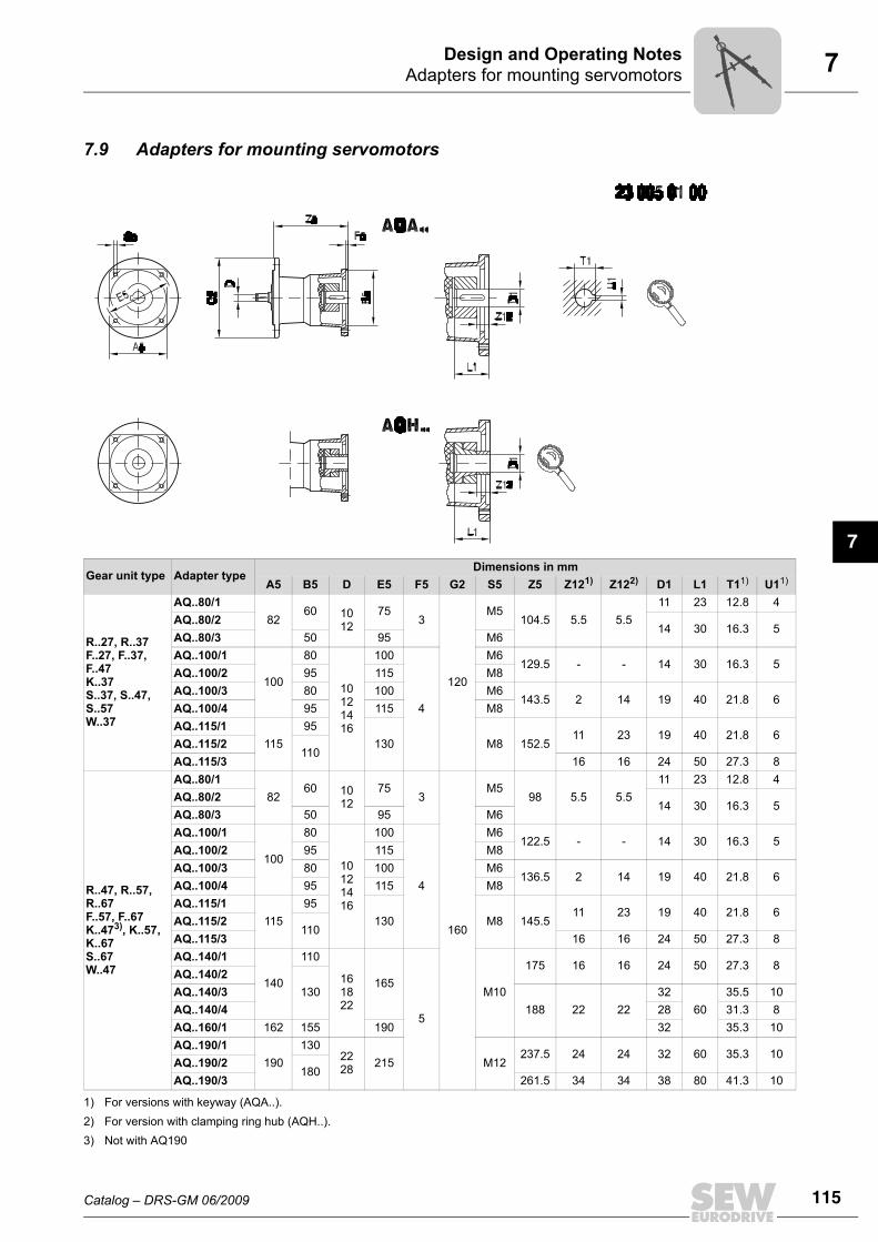
7.9 Adapters for mounting servomotors
Gear unit type Adapter typeDimensions in mm
A5 B5 D E5 F5 G2 S5 Z5 Z121)
1) For versions with keyway (AQA..).
Z122)
2) For version with clamping ring hub (AQH..).
D1 L1 T11) U11)
R..27, R..37F..27, F..37, F..47K..37S..37, S..47,S..57W..37
AQ..80/182
60 1012
753
120
M5104.5 5.5 5.5
11 23 12.8 4AQ..80/2
14 30 16.3 5AQ..80/3 50 95 M6AQ..100/1
100
80
10121416
100
4
M6129.5 - - 14 30 16.3 5
AQ..100/2 95 115 M8AQ..100/3 80 100 M6
143.5 2 14 19 40 21.8 6AQ..100/4 95 115 M8AQ..115/1
11595
130 M8 152.511 23 19 40 21.8 6
AQ..115/2110
AQ..115/3 16 16 24 50 27.3 8
R..47, R..57,R..67F..57, F..67K..473), K..57,K..67S..67W..47
3) Not with AQ190
AQ..80/182
60 1012
753
160
M598 5.5 5.5
11 23 12.8 4AQ..80/2
14 30 16.3 5AQ..80/3 50 95 M6AQ..100/1
100
80
10121416
100
4
M6122.5 - - 14 30 16.3 5
AQ..100/2 95 115 M8AQ..100/3 80 100 M6
136.5 2 14 19 40 21.8 6AQ..100/4 95 115 M8AQ..115/1
11595
130 M8 145.511 23 19 40 21.8 6
AQ..115/2110
AQ..115/3 16 16 24 50 27.3 8AQ..140/1
140
110
161822
165
5
M10
175 16 16 24 50 27.3 8AQ..140/2
130AQ..140/3188 22 22
3260
35.5 10AQ..140/4 28 31.3 8AQ..160/1 162 155 190 32 35.3 10AQ..190/1
190130
2228 215 M12
237.5 24 24 32 60 35.3 10AQ..190/2
180AQ..190/3 261.5 34 34 38 80 41.3 10
116 Catalog – DRS-GM 06/2009
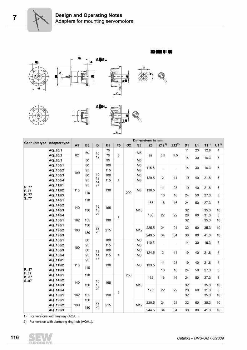
7 Adapters for mounting servomotorsDesign and Operating Notes
Gear unit type Adapter typeDimensions in mm
A5 B5 D E5 F5 G2 S5 Z5 Z121) Z122) D1 L1 T11) U11)
R..77F..77K..77S..77
AQ..80/182
60 1012
753
200
M592 5.5 5.5
11 23 12.8 4AQ..80/2 75
14 30 16.3 5AQ..80/3 50 95 M6AQ..100/1
100
80
10121416
100
4
M6115.5 - - 14 30 16.3 5
AQ..100/2 95 115 M8AQ..100/3 80 100 M6
129.5 2 14 19 40 21.8 6AQ..100/4 95 115 M8AQ..115/1
11595
130 M8 138.511 23 19 40 21.8 6
AQ..115/2110
AQ..115/3 16 16 24 50 27.3 8AQ..140/1
140
110
161822
165
5
M10
167 16 16 24 50 27.3 8AQ..140/2
130AQ..140/3180 22 22
3260
35.3 10AQ..140/4 28 31.3 8AQ..160/1 162 155 190 32 35.3 10AQ..190/1
190130
2228 215 M12
225.5 24 24 32 60 35.3 10AQ..190/2
180AQ..190/3 249.5 34 34 38 80 41.3 10
R..87F..87K..87S..87
AQ..100/1
100
80
121416
100
4
250
M6110.5 - - 14 30 16.3 5
AQ..100/2 95 115 M8AQ..100/3 80 100 M6
124.5 2 14 19 40 21.8 6AQ..100/4 95 115 M8AQ..115/1
11595
130 M8 133.511 23 19 40 21.8 6
AQ..115/2110
AQ..115/3 16 16 24 50 27.3 8AQ..140/1
140
110
161822
165
5
M10
162 16 16 24 50 27.3 8AQ..140/2
130AQ..140/3175 22 22
3260
35.3 10AQ..140/4 28 31.3 8AQ..160/1 162 155 190 32 35.3 10AQ..190/1
190130
2228 215 M12
220.5 24 24 32 60 35.3 10AQ..190/2
180AQ..190/3 244.5 34 34 38 80 41.3 10
1) For versions with keyway (AQA..).2) For version with clamping ring hub (AQH..).
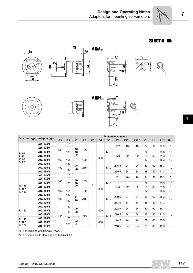
Catalog – DRS-GM 06/2009 117
7Adapters for mounting servomotorsDesign and Operating Notes
7
Gear unit type Adapter typeDimensions in mm
A5 B5 D E5 F5 G2 S5 Z5 Z121) Z122) D1 L1 T11) U11)
R..97F..97K..97S..97
AQ..140/1
140
110
161822
165
5
300
M10
157 16 16 24 50 27.3 8AQ..140/2
130AQ..140/3170 22 22
3260
35.3 10AQ..140/4 28 31.3 8AQ..160/1 162 155 190 32 35.3 10AQ..190/1
190130
2228 215 M12
215.5 24 24 32 60 35.310AQ..190/2
180AQ..190/3 239.5 34 34 38 80 41.3
R..107F..107K..107
AQ..140/1
140
110
161822
165
350
M10
151 16 16 24 50 27.3 8AQ..140/2
130AQ..140/3164 22 22
3260
35.3 10AQ..140/4 28 31.3 8AQ..160/1 162 155 190 32 35.3 10AQ..190/1
190130
2228 215 M12
209.5 24 24 32 60 35.310AQ..190/2
180AQ..190/3 233.5 34 34 38 80 41.3
R..137AQ..190/1
190
1302228
215
400
M12
202.5 24 24 32 60 35.3
10
AQ..190/2180
AQ..190/3 226.5 34 34 38 80 41.3
R..147F..127K..127
AQ..190/1 1302228 450
194.5 24 24 32 60 35.3AQ..190/2
180AQ..190/3 218.5 34 34 38 80 41.3
1) For versions with keyway (AQA..).2) For version with clamping ring hub (AQH..).
118 Catalog – DRS-GM 06/2009
7 Fastening the gear unitDesign and Operating Notes
7.10 Fastening the gear unitUse bolts of quality 8.8 to fasten gear units and gearmotors.
Exception Use bolts of quality 10.9 to fasten the customer flange to transmit the rated torques forthe following flange-mounted (RF ../RZ..) and foot/flange-mounted helical gearmotors(R..F):• RF37, R37F with flange ∅ 120 mm• RF47, R47F with flange ∅ 140 mm• RF57, R57F with flange ∅ 160 mm• RZ37 ... RZ87
7.11 Torque armsAvailable torque arms
Torque arms for KH167.., KH187..
As standard, torque arms are not available for gear unit sizes KH167.. and KH187...Consult SEW-EURODRIVE for design proposals if you require torque arms for thesegear units.
Gear unitSize
27 37 47 57 67 77
KA, KH, KV, KT - 643 425 8 643 428 2 643 431 2 643 431 2 643 434 7
SA, SH, ST - 126 994 1 644 237 4 644 240 4 644 243 9 644 246 3
FA, FH, FV, FTRubber buffer (2 pieces) 013 348 5 013 348 5 013 348 5 013 348 5 013 348 5 013 349 3
Gear unitSize
87 97 107 127 157
KA, KH, KV, KT 643 437 1 643 440 1 643 443 6 643 294 8 -
SA, SH, ST 644 249 8 644 252 8 - - -
FA, FH, FV, FTRubber buffer (2 pieces) 013 349 3 013 350 7 013 350 7 013 351 5 013 347 7
Gear unitSize
10 20 30 37 47
WA 1 061 021 9 1 68 073 0 1 68 011 0 1 061 129 0 1 061 187 8
Catalog – DRS-GM 06/2009 119
7Flange contours of RF.. and R..F gear unitsDesign and Operating Notes
7
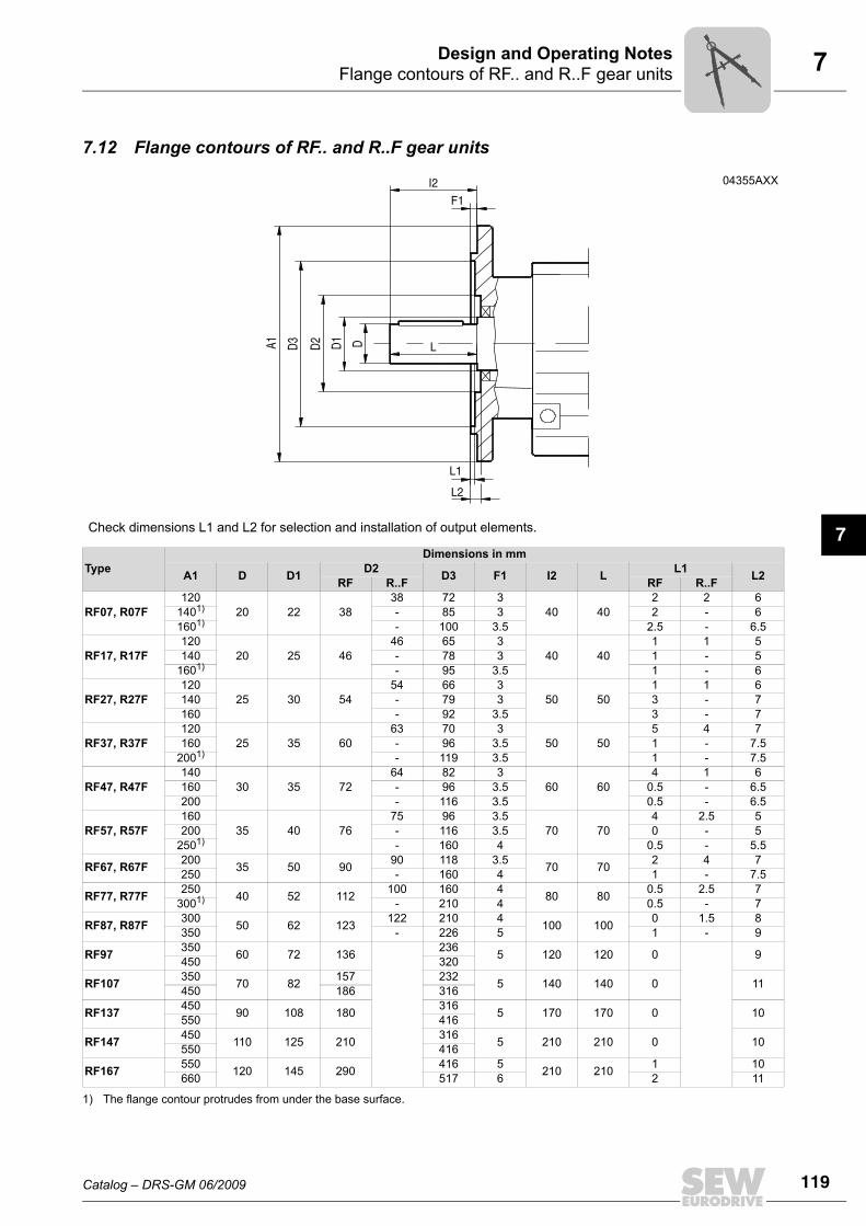
7.12 Flange contours of RF.. and R..F gear units
04355AXX
Check dimensions L1 and L2 for selection and installation of output elements.
TypeDimensions in mm
A1 D D1 D2 D3 F1 I2 L L1 L2RF R..F RF R..F
RF07, R07F120
20 22 3838 72 3
40 402 2 6
1401)
1) The flange contour protrudes from under the base surface.
- 85 3 2 - 61601) - 100 3.5 2.5 - 6.5
RF17, R17F120
20 25 4646 65 3
40 401 1 5
140 - 78 3 1 - 51601) - 95 3.5 1 - 6
RF27, R27F120
25 30 5454 66 3
50 501 1 6
140 - 79 3 3 - 7160 - 92 3.5 3 - 7
RF37, R37F120
25 35 6063 70 3
50 505 4 7
160 - 96 3.5 1 - 7.52001) - 119 3.5 1 - 7.5
RF47, R47F140
30 35 7264 82 3
60 604 1 6
160 - 96 3.5 0.5 - 6.5200 - 116 3.5 0.5 - 6.5
RF57, R57F160
35 40 7675 96 3.5
70 704 2.5 5
200 - 116 3.5 0 - 52501) - 160 4 0.5 - 5.5
RF67, R67F 200 35 50 90 90 118 3.5 70 70 2 4 7250 - 160 4 1 - 7.5
RF77, R77F 250 40 52 112 100 160 4 80 80 0.5 2.5 73001) - 210 4 0.5 - 7
RF87, R87F 300 50 62 123 122 210 4 100 100 0 1.5 8350 - 226 5 1 - 9
RF97 350 60 72 136 236 5 120 120 0 9450 320
RF107 350 70 82 157 232 5 140 140 0 11450 186 316
RF137 450 90 108 180 316 5 170 170 0 10550 416
RF147 450 110 125 210 316 5 210 210 0 10550 416
RF167 550 120 145 290 416 5 210 210 1 10660 517 6 2 11
120 Catalog – DRS-GM 06/2009
7 Flange contours of FF.., KF.., SF.. and WF.. gear unitsDesign and Operating Notes
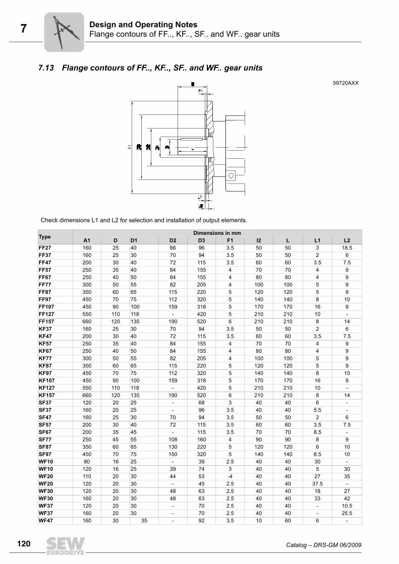
7.13 Flange contours of FF.., KF.., SF.. and WF.. gear units
59720AXX
Check dimensions L1 and L2 for selection and installation of output elements.
Type Dimensions in mmA1 D D1 D2 D3 F1 I2 L L1 L2
FF27 160 25 40 66 96 3.5 50 50 3 18.5FF37 160 25 30 70 94 3.5 50 50 2 6FF47 200 30 40 72 115 3.5 60 60 3.5 7.5FF57 250 35 40 84 155 4 70 70 4 9FF67 250 40 50 84 155 4 80 80 4 9FF77 300 50 55 82 205 4 100 100 5 9FF87 350 60 65 115 220 5 120 120 5 9FF97 450 70 75 112 320 5 140 140 8 10FF107 450 90 100 159 318 5 170 170 16 9FF127 550 110 118 - 420 5 210 210 10 -FF157 660 120 135 190 520 6 210 210 8 14KF37 160 25 30 70 94 3.5 50 50 2 6KF47 200 30 40 72 115 3.5 60 60 3.5 7.5KF57 250 35 40 84 155 4 70 70 4 9KF67 250 40 50 84 155 4 80 80 4 9KF77 300 50 55 82 205 4 100 100 5 9KF87 350 60 65 115 220 5 120 120 5 9KF97 450 70 75 112 320 5 140 140 8 10KF107 450 90 100 159 318 5 170 170 16 9KF127 550 110 118 - 420 5 210 210 10 -KF157 660 120 135 190 520 6 210 210 8 14SF37 120 20 25 - 68 3 40 40 6 -SF37 160 20 25 - 96 3.5 40 40 5.5 -SF47 160 25 30 70 94 3.5 50 50 2 6SF57 200 30 40 72 115 3.5 60 60 3.5 7.5SF67 200 35 45 - 115 3.5 70 70 8.5 -SF77 250 45 55 108 160 4 90 90 8 9SF87 350 60 65 130 220 5 120 120 6 10SF97 450 70 75 150 320 5 140 140 8.5 10WF10 80 16 25 - 39 2.5 40 40 30 -WF10 120 16 25 39 74 3 40 40 5 30WF20 110 20 30 44 53 -4 40 40 27 35WF20 120 20 30 - 45 2.5 40 40 37.5 -WF30 120 20 30 48 63 2.5 40 40 18 27WF30 160 20 30 48 63 2.5 40 40 33 42WF37 120 20 30 - 70 2.5 40 40 - 10.5WF37 160 20 30 - 70 2.5 40 40 - 25.5WF47 160 30 35 - 92 3.5 10 60 6 -
Catalog – DRS-GM 06/2009 121
7Flange contours of FAF.., KAF.., SAF.. and WAF.. gear unitsDesign and Operating Notes
7
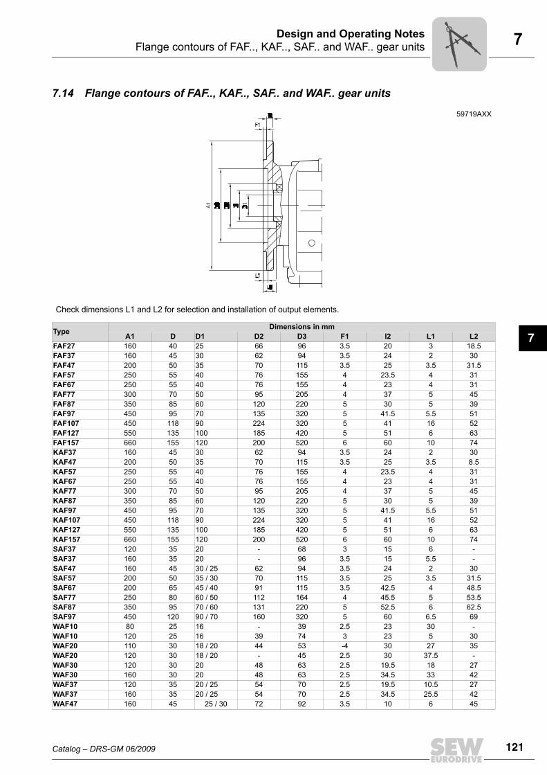
7.14 Flange contours of FAF.., KAF.., SAF.. and WAF.. gear units
59719AXX
Check dimensions L1 and L2 for selection and installation of output elements.
Type Dimensions in mmA1 D D1 D2 D3 F1 I2 L1 L2
FAF27 160 40 25 66 96 3.5 20 3 18.5FAF37 160 45 30 62 94 3.5 24 2 30FAF47 200 50 35 70 115 3.5 25 3.5 31.5FAF57 250 55 40 76 155 4 23.5 4 31FAF67 250 55 40 76 155 4 23 4 31FAF77 300 70 50 95 205 4 37 5 45FAF87 350 85 60 120 220 5 30 5 39FAF97 450 95 70 135 320 5 41.5 5.5 51FAF107 450 118 90 224 320 5 41 16 52FAF127 550 135 100 185 420 5 51 6 63FAF157 660 155 120 200 520 6 60 10 74KAF37 160 45 30 62 94 3.5 24 2 30KAF47 200 50 35 70 115 3.5 25 3.5 8.5KAF57 250 55 40 76 155 4 23.5 4 31KAF67 250 55 40 76 155 4 23 4 31KAF77 300 70 50 95 205 4 37 5 45KAF87 350 85 60 120 220 5 30 5 39KAF97 450 95 70 135 320 5 41.5 5.5 51KAF107 450 118 90 224 320 5 41 16 52KAF127 550 135 100 185 420 5 51 6 63KAF157 660 155 120 200 520 6 60 10 74SAF37 120 35 20 - 68 3 15 6 -SAF37 160 35 20 - 96 3.5 15 5.5 -SAF47 160 45 30 / 25 62 94 3.5 24 2 30SAF57 200 50 35 / 30 70 115 3.5 25 3.5 31.5SAF67 200 65 45 / 40 91 115 3.5 42.5 4 48.5SAF77 250 80 60 / 50 112 164 4 45.5 5 53.5SAF87 350 95 70 / 60 131 220 5 52.5 6 62.5SAF97 450 120 90 / 70 160 320 5 60 6.5 69WAF10 80 25 16 - 39 2.5 23 30 -WAF10 120 25 16 39 74 3 23 5 30WAF20 110 30 18 / 20 44 53 -4 30 27 35WAF20 120 30 18 / 20 - 45 2.5 30 37.5 -WAF30 120 30 20 48 63 2.5 19.5 18 27WAF30 160 30 20 48 63 2.5 34.5 33 42WAF37 120 35 20 / 25 54 70 2.5 19.5 10.5 27WAF37 160 35 20 / 25 54 70 2.5 34.5 25.5 42WAF47 160 45 25 / 30 72 92 3.5 10 6 45
122 Catalog – DRS-GM 06/2009
7 Fixed coversDesign and Operating Notes
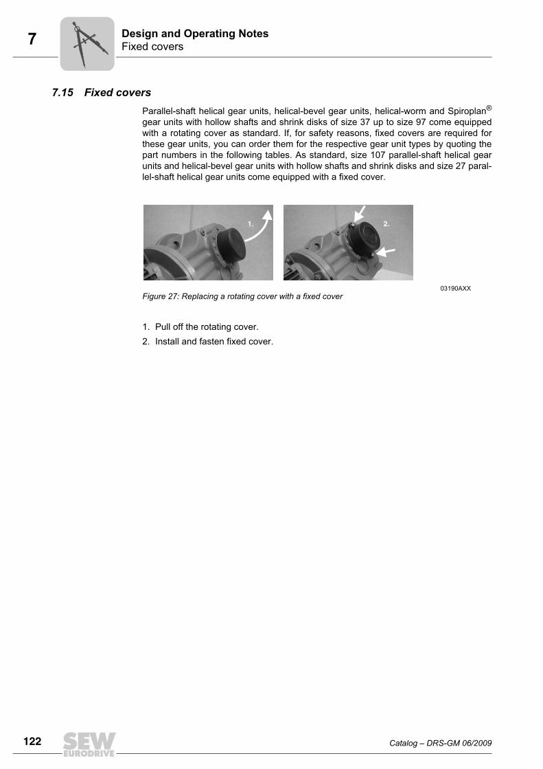
7.15 Fixed coversParallel-shaft helical gear units, helical-bevel gear units, helical-worm and Spiroplan®
gear units with hollow shafts and shrink disks of size 37 up to size 97 come equippedwith a rotating cover as standard. If, for safety reasons, fixed covers are required forthese gear units, you can order them for the respective gear unit types by quoting thepart numbers in the following tables. As standard, size 107 parallel-shaft helical gearunits and helical-bevel gear units with hollow shafts and shrink disks and size 27 paral-lel-shaft helical gear units come equipped with a fixed cover.
1. Pull off the rotating cover.2. Install and fasten fixed cover.
03190AXXFigure 27: Replacing a rotating cover with a fixed cover
1. 2.
Catalog – DRS-GM 06/2009 123
7Fixed coversDesign and Operating Notes
7
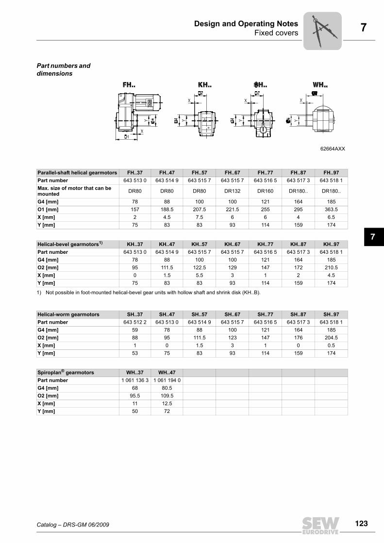
Part numbers and dimensions
62664AXX
Parallel-shaft helical gearmotors FH..37 FH..47 FH..57 FH..67 FH..77 FH..87 FH..97Part number 643 513 0 643 514 9 643 515 7 643 515 7 643 516 5 643 517 3 643 518 1Max. size of motor that can be mounted DR80 DR80 DR80 DR132 DR160 DR180.. DR180..
G4 [mm] 78 88 100 100 121 164 185O1 [mm] 157 188.5 207.5 221.5 255 295 363.5X [mm] 2 4.5 7.5 6 6 4 6.5Y [mm] 75 83 83 93 114 159 174
Helical-bevel gearmotors1) KH..37 KH..47 KH..57 KH..67 KH..77 KH..87 KH..97Part number 643 513 0 643 514 9 643 515 7 643 515 7 643 516 5 643 517 3 643 518 1G4 [mm] 78 88 100 100 121 164 185O2 [mm] 95 111.5 122.5 129 147 172 210.5X [mm] 0 1.5 5.5 3 1 2 4.5Y [mm] 75 83 83 93 114 159 174
1) Not possible in foot-mounted helical-bevel gear units with hollow shaft and shrink disk (KH..B).
Helical-worm gearmotors SH..37 SH..47 SH..57 SH..67 SH..77 SH..87 SH..97Part number 643 512 2 643 513 0 643 514 9 643 515 7 643 516 5 643 517 3 643 518 1G4 [mm] 59 78 88 100 121 164 185O2 [mm] 88 95 111.5 123 147 176 204.5X [mm] 1 0 1.5 3 1 0 0.5Y [mm] 53 75 83 93 114 159 174
Spiroplan® gearmotors WH..37 WH..47Part number 1 061 136 3 1 061 194 0G4 [mm] 68 80.5O2 [mm] 95.5 109.5X [mm] 11 12.5Y [mm] 50 72
124 Catalog – DRS-GM 06/2009
7 Condition monitoring: Oil aging and vibration sensorDesign and Operating Notes
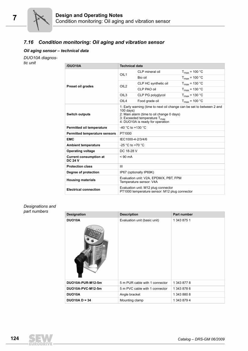
7.16 Condition monitoring: Oil aging and vibration sensorOil aging sensor – technical dataDUO10A diagnos-tic unit
Designations and part numbers
/DUO10A Technical data
Preset oil grades
OIL1CLP mineral oil Tmax = 100 °C
Bio oil Tmax = 100 °C
OIL2CLP HC synthetic oil Tmax = 130 °C
CLP PAO oil Tmax = 130 °C
OIL3 CLP PG polyglycol Tmax = 130 °C
OIL4 Food grade oil Tmax = 100 °C
Switch outputs
1: Early warning (time to next oil change can be set to between 2 and 100 days)2: Main alarm (time to oil change 0 days)3: Exceeded temperature Tmax4: DUO10A is ready for operation
Permitted oil temperature -40 °C to +130 °C
Permitted temperature sensors PT1000
EMC IEC1000-4-2/3/4/6
Ambient temperature -25 °C to +70 °C
Operating voltage DC 18-28 V
Current consumption at DC 24 V
< 90 mA
Protection class III
Degree of protection IP67 (optionally IP69K)
Housing materials Evaluation unit: V2A, EPDM/X, PBT, FPMTemperature sensor: V4A
Electrical connection Evaluation unit: M12 plug connectorPT1000 temperature sensor: M12 plug connector
Designation Description Part number
DUO10A Evaluation unit (basic unit) 1 343 875 1
DUO10A-PUR-M12-5m 5 m PUR cable with 1 connector 1 343 877 8
DUO10A-PVC-M12-5m 5 m PVC cable with 1 connector 1 343 878 6
DUO10A Angle bracket 1 343 880 8
DUO10A D = 34 Mounting clamp 1 343 879 4
Catalog – DRS-GM 06/2009 125
7Condition monitoring: Oil aging and vibration sensorDesign and Operating Notes
7Mounting on stan-dard gear units (R, F, K, S)
Adapter for mounting the PT1000 temperature sensor in screw plug holes:
Mounting base for installing the diagnostic unit at the gear unit with an angle bracket:
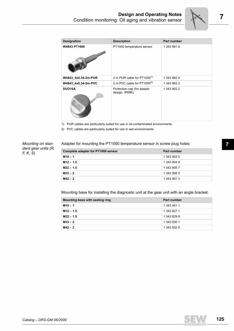
W4843 PT1000 PT1000 temperature sensor 1 343 881 6
W4843_4x0.34-2m-PUR 2 m PUR cable for PT10001) 1 343 882 4
W4843_4x0.34-2m-PVC 2 m PVC cable for PT10002) 1 343 883 2
DUO10A Protection cap (for aseptic design, IP69K)
1 343 902 2
1) PUR cables are particularly suited for use in oil-contaminated environments.2) PVC cables are particularly suited for use in wet environments.
Designation Description Part number
Complete adapter for PT1000 sensor Part number
M10 × 1 1 343 903 0
M12 × 1.5 1 343 904 9
M22 × 1.5 1 343 905 7
M33 × 2 1 343 906 5
M42 × 2 1 343 907 3
Mounting base with sealing ring Part number
M10 × 1 1 343 441 1
M12 × 1.5 1 343 827 1
M22 × 1.5 1 343 829 8
M33 × 2 1 343 830 1
M42 × 2 1 343 832 8
126 Catalog – DRS-GM 06/2009
7 Condition monitoring: Oil aging and vibration sensorDesign and Operating Notes
Vibration sensor technical data
DUV10A and DUV30A diagnos-tics units
Designations and part numbers
/DUV10A and DUV30A Technical data
Measuring range ± 20 g
Frequency range 0.125 ... 500 Hz
Spectral resolution 0.125 Hz
Diagnostic processes FFT, envelope-FFT, trend analysis
Minimum measuring period 8.0 s
Speed range 12 ... 3500 min-1
Switch outputs 1: Early warning2: Main alarm
Operating voltage DC 10-32 V
Current consumption at DC 24 V
100 mA
Protection class III
EMC IEC1000-4-2/3/4/6
Overload capacity 100 g
Ambient temperature -30 °C to +60 °C
Degree of protection IP67
Housing materials Zinc die-casting, coating based on epoxy finish, polyester membrane keypad
Electrical connection for sup-ply and switching output M12 plug connector
Electrical connection RS-232 for communication M8 plug connector
Certificates and standards CE, UL
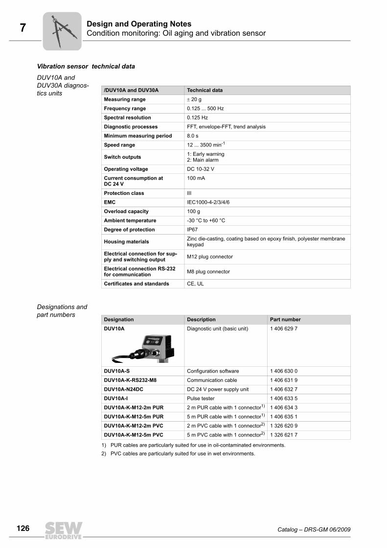
Designation Description Part number
DUV10A Diagnostic unit (basic unit) 1 406 629 7
DUV10A-S Configuration software 1 406 630 0
DUV10A-K-RS232-M8 Communication cable 1 406 631 9
DUV10A-N24DC DC 24 V power supply unit 1 406 632 7
DUV10A-I Pulse tester 1 406 633 5
DUV10A-K-M12-2m PUR 2 m PUR cable with 1 connector1)
1) PUR cables are particularly suited for use in oil-contaminated environments.
1 406 634 3
DUV10A-K-M12-5m PUR 5 m PUR cable with 1 connector1) 1 406 635 1
DUV10A-K-M12-2m PVC 2 m PVC cable with 1 connector2)
2) PVC cables are particularly suited for use in wet environments.
1 326 620 9
DUV10A-K-M12-5m PVC 5 m PVC cable with 1 connector2) 1 326 621 7
Catalog – DRS-GM 06/2009 127
7Condition monitoring: Oil aging and vibration sensorDesign and Operating Notes
7
Mounting on stan-dard gear units (R, F, K, S)
Mounting base for installing the diagnostic unit at the gear unit:
Mounted on motor Mounting base for installing the diagnostic unit at the motor:
Mounting base with sealing ring Part number
M10 × 1 1 343 441 1
M12 × 1.5 1 343 827 1
M22 × 1.5 1 343 829 8
M33 × 2 1 343 830 1
M42 × 2 1 343 832 8
Fastening element Part number
M12, for motor sizes 132M to 180 1 343 842 5
M16, for motor sizes 200 to 280 1 343 844 1