Embed Size (px)
Citation preview

6. FUEL SYSTEM
SYSTEM COMPONENTS 6-2
SERVICEINFORMATION 6-3
TROUBLESHOOTING 6-4
AIR CLEANERHOUSING 6-5
CARBURETORREMOVAL 6-6
-CARBURETORDISASSEMBl Y 6-8
CARBURETORASSEMBLY 6-14
CARBURETORINSTALLATION 6-21
PilOT SCREWADJUSTMENT 6-23
6-1

FUEL SYSTEM
SYSTEM COMPONENTS
6-2
I

FUEL SYSTEM
SERVICEINFORMATIONGENERAL
' ' · Bending or twisting the control cable will impair smooth operation and could cause the cable to stick or bind, resultingin loss of vehicle control.· Work in a well ventilated area. Smoking or allowing flames or sparks in the work area or where gasoline is stored cancause a fire or explosion.· When disassembling the fuel system parts, note the locations of the O-rings. Replace them with new ones on reassem-bly.. Before removing the carburetor, place an approved gasoline container under the' carburetor drain hose, loosen thedrain screw and drain the carburetor.
' ' . After removing the carburetor, wrap the intake port of the engine with a shop towel or cover it with pieces of tape toprevent any foreign material from dropping into the engine.. Ifthe vehicle is to be stored for more than one month, drain the float chamber. Fuel left in the float chamber may causeclogged jets, resulting in hard starting or poor driveability.· Refer to page 3-6 for fuel tank removal and installation.. Refer to page 16-20 for throttle position sensor service.
SPECIFICATIONS
TORQUE VALUES
Starting enrichment (SE) valve nutHot start valve nut
3 N.m (0.3 kgf.m, 2.2 Ibf.ft)3 N'm (0.3 kgf.m, 2.2 Ibf.ft)
TOOL
Carburetor float level gauge07401-0010000
6-3
ITEM SPECIFICATIONSCarburetor identification number QA16A
Main jet #118
Slow jet #48Pilot screw opening See page 6-23Float level 15.9 mm (0.63 in)Idle speed 1,600 + 100 rpmThrottle grip free play 3 - 8 mm (1/8 - 5/16 in)Hot starter lever free play 2 - 3 mm (1/16 -1/8 in)

FUEL SYSTEM
TROUBLESHOOTINGEngine cranks but won't start· No fuel in tank· No fuel to carburetor
- Clogged fuel strainer- Clogged fuel line- Clogged fuel tank breather hose
· Too much fuel getting to the engine- Clogged air cleaner- Flooded carburetor
· Intake air leak· Contaminated/deteriorated fuel- Clogged jets· Clogged starting enrichment (SE)valve circuit· Improper choke operation
· Improper throttle operation· No spark at plug (faulty ignition system - page 16-5)Lean mixture· Clogged fuel jets· Faulty float valve· Float level too low· Restricted fuel line· Clogged carburetor air vent hose· Restricted fuel tank breather hose· Intake air leak· Faulty throttle valveRich mixture· SE valve open· Clogged air jets· Faulty float valve· Float level too high· Dirty air cleaner· Worn jet needle or needle jet
Engine stalls, hard to start, rough idling· Restricted fuel line· Fuel mixture too lean/rich· Contaminated/deteriorated fuel
- Clogged jets· Intake air leak· Misadjusted idle speed· Restricted fuel tank breather hose· Dirty air cleaner· Misadjusted pilot screw· Clogged slow circuit or SE valve circuit· Faulty ignition system (page 16-5)
Afterburn when engine braking is used· Lean mixture in slow circuit· Faulty ignition system (page 16-5)
Backfiring or misfiring during acceleration· Lean mixture· Faulty ignition system (page 16-5)
Poor performance (driveability) and poor fuel economy· Clogged fuel system· Faulty ignition system (page 16-5)
6-4
I

FUEL SYSTEM
AIR CLEANER HOUSINGREMOV AL/INST ALLATIONRemove the fuel tank (page 3-6).
Remove the two trim clips and heat guard rubber.
Disconnect the crankcase breather hose from the 3-way joint.Remove the breather hose from the clamps.
Loosen the connecting hose band screw.
Loosen the band screw and remove the air chamberfrom the connecting hose.
~CONNECTING HOSE BAND SCREW
~
I
6-5

FUEL SYSTEM
Remove the three mounting bolts, wire clamp andthe air cleaner housing from the frame.Installation is in the reverse order of removal.
CARBURETOR REMOVALRemove the fuel tank (page 3-6).
Disconnect the drain hose from the carburetor.
Disconnect the carburetor heater 2P and throttleposition sensor 3P connectors, and remove theirwires from the clamp.
6-6
I

FUEL SYSTEM
Slide the rubber cap off the hot start valve nut.Loosen the hot start valve nut and remove the hotstart valve from the carburetor.
Loosen the band screws and remove carburetorfrom the insulator and connecting hose.
Remove the screw and throttle drum cover from thecarburetor.
Slide the rubber cap off the throttle cable adjuster.Loosen the lock nut and remove the throttle cableadjuster from the carburetor.Disconnect the throttle cable from the throttle drumand remove the carburetor.
oBAND SCREWS
I
6-7

FUEL SYSTEM
CARBURETOR DISASSEMBL VAIR CUT-OFF VALVEDisconnect the vacuum hose from the air cut-offvalve.Remove the screw and air cut-off valve.Remove the a-rings and slow air jet.
Apply vacuum to the vacuum port.The vacuum should maintained.Air should not flow through the valve ports whenthe vacuum is applied, and should flow when thevacuum is not applied.
STARTING ENRICHMENT (SE) VALVERemove the screw, collar and choke lever whileunhooking it from the SE valve end.
Loosen the SE valve nut and remove the SE valvefrom the carburetor.
VACUUM HOSE SCREW
VACUUM PORT
VALVEPORTS
6-8
I

FUEL SYSTEM
Remove the boot, nut and spring from the SE valve.
Check the SE valve face for scores, scratches orwear.Check the SE valve seat at the tip of the valve forstepped wear.Check the seal ring for deterioration, wear or dam-age.
THROTTLE VALVERemovethe airvent hoses.
Removethe four screws, top cover and O-ring.
Remove the setting screw and spring washer.Pull out the link arm shaft and remove the thrustwasher and return spring.
Remove the throttle valve assembly from the carbu-retor body.
SE VALVE
SPRING
AIR VENT HOSES
I
6-9

FUEL SYSTEM
Remove the two screws and the link arm with thespring from the throttle valve.
Remove the jet needle from the throttle valve.
Check the jet needle for stepped wear or damage.Check the throttle valve for scoring, scratches ordamage.
ACCELERATOR PUMPRemove the bolt, collar, accelerator pump link arm,plastic washer, plain washer and spring washer ifnecessary.
Remove the three screws while holding the acceler-ator pump cover.
LINK ARM THROTTLE VALVE
SCREWS
THROTTLE VALVE
~JET NEEDLE
6-10
I
FUEL SYSTEM
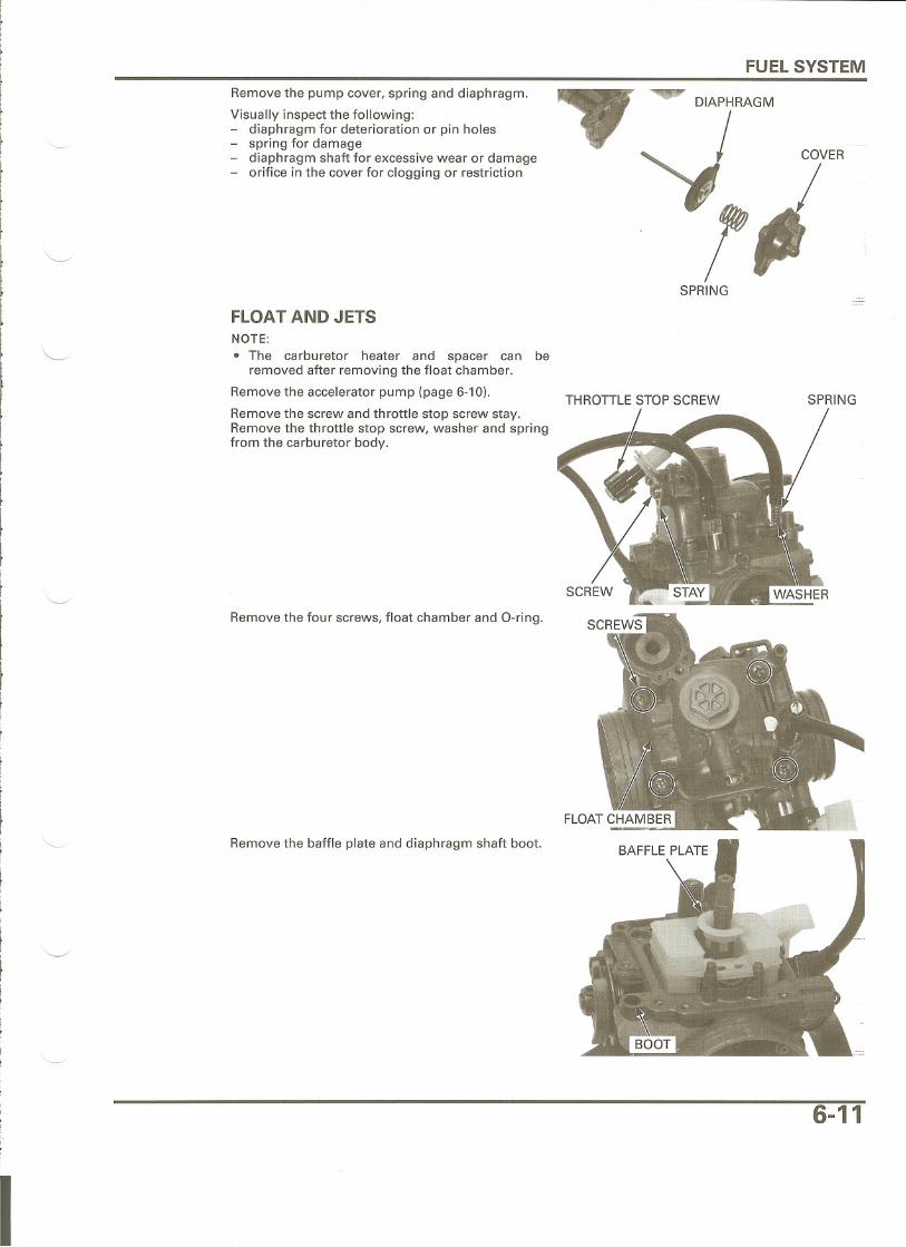
Remove the pump cover, springand diaphragm.Visually inspect the following:
diaphragm for deterioration or pin holesspring for damagediaphragm shaft for excessive wear or damageorifice in the cover for clogging or restriction
DIAPHRAGM
SPRING---
FLOAT AND JETSNOTE:
· The carburetor heater and spacer can beremoved after removing the float chamber.
Remove the accelerator pump (page 6-10). THROTTLESTOPSCREWRemove the screw and throttle stop screw stay.Remove the throttle stop screw, washer and springfrom the carburetor body.
Remove the four screws, float chamber and a-ring.
Remove the baffle plate and diaphragm shaft boot.
SPRING
I
6-11

FUEL SYSTEM
Handle all jets with'care. They can eas-
ily be scored orscratched.
Damage to the pilotscrew seat will
occur if the pilotscrew is tightened
against the seat.
Remove the float pin by gently tapping itwith a suit-able driver (0.0.: 2 mm).Remove the float and float valve.
Check the float for damage.
Inspect the float valve seat for scores, scratches,clogging and damage.
Check the tip of the float valve where it contacts thevalve seat for stepped wear or contamination.
Replace the float valve if the tip is worn or comtami-nated.
Check the operation of the float valve.
Remove the main jet, loosen the lock nut andremove the needle jet holder and needle jet.Remove the slow jet.Rubber plug and starter jet.
Turn the pilot screw in and record the number ofturns it takes before it seats lightly.Remove the pilot screw, spring, washer and O-ring.
Inspect each jet for wear or damage.
Clean all jets with non-flammable or high flash pointsolvent and blow them open with compressed air.
Check the pilot screw for stepped wear or damage.
6-12

FUEL SYSTEM
Cleaning the air andfuel passages witha piece of wire willdamage the carbu-
re tor body.
CARBURETOR CLEANINGRemove the fuel hose and strainer screen from thecarburetor body.
Clean the strainer screen with compressed air.
Remove the following:
air cut-off valve (page 6-8)starting enrichment (SE) valve (page 6-8)throttle valve (page 6-9)float, all jets and pilot screw (page 6-11)
Blow open all air and fuel passages in the carbure-tor body with compressed air.
STRAINERSCREEN
I
6-13

FUEL SYSTEM
CARBURETOR ASSEMBLY
THRUST WASHER
AIR CUT-OFFVALVE
F.c NEEDLECLIP
JET NEEDLE
/ - THROTTLE VALVE
r-- FLOATVALVE
,y FLOATPIN~
FLOAT
STARTER JET
RUBBER PLUG
STARTING ENRICHMENT(SE) VALVE
BOOT
ACCELERATOR THROTTLEPUMP DIAPHRAGM STOPSCREW
6-14

FUEL SYSTEM
Damage to the pilotscrew seat will
occur if the pilotscrew is tightened
against the seat.
Handle all jets withcare. They can eas-
ily be scored orscratched.
JETS AND FLOATInstall the pilot screw with the spring, washer and anew O-ring and return it to its original position asnoted during removal.Perform the pilot screw adjustment if a new pilotscrew is installed (page 6-23).
Install the needle jet and needle jet holder, tightenthe lock nut and install the main jet.Install the slow jet.Install the starter jet and rubber plug.
Hang the float valve onto the float arm lip.Install the float with the float valve and insert thefloat pin.
Install the float pin in position as shown by tappingit with a suitable driver (0.0.: 2 mm).
Set the carburetor so that the float valve end justcontacts the float arm lip, measure the float levelwith the special tool.
TOOL:Carburetor float level gauge 07401-0010000
I
Float level: 15.9 mm (0.63 in)
If the float level is out of specification, replace thefloat assembly.
6-15

FUEL SYSTEM
Install the baffle plate by aligning the groove withthe lug on the carburetor body as shown.Install a new diaphragm shaft boot.
Install a new a-ring in the float chamber groove.Install the float chamber onto the carburetor body.
Install the four screws and tighten them.
Install the throttle stop screw into the carburetor THROTTLE STOP SCREWbody with the spring and washer.Install the stay by aligning the hole with the pin andtighten the screw securely.
SPRING
6-16

FUEL SYSTEM
Turn the throttle stop screw to align the butterflythrottle valve with the edge of the outside by-passhole in the carburetor.
Install the accelerator pump (page 6-17)
ACCELERATOR PUMPInstall the diaphragm shaft into the float chamberthrough the boot while slowly turn it to prevent theboot from damaging.Set the diaphragm rib into the groove properly.Install the spring and accelerator pump cover.
Install the three screws and tighten them securelybeing careful not to pinch the diaphragm.
Install the spring washer, plain washer, plasticwasher, accelerator pump link arm and collar, andtighten the bolt securely if they were removed.
7RAGM
!COVER
SPRING
I
6-17

FUEL SYSTEM
THROTTLE VALVEInstall the needle clip on the jet needle.
STANDARD CLIP POSITION: 3rd groove from top
Install the jet needle into the throttle valve.
Install the link arm into the throttle valve and tightenthe two screws.
Install the throttle valve assembly into the carbure-tor body, being careful not to damage the jet nee-dle.
Set the thrust washer between the throttle valve linkarm and carburetor body (throttle drum side).Install the return spring between the carburetorbody and throttle drum link arm.Insert the link arm shaft through the drum link arm,return spring, carburetor body, thrust washer andvalve link arm while hanging the spring ends asshown.
Align the screw holes in the link arm and shaft,install the spring washer and screw, and tighten thescrew securely.
Turn the throttle drum and check for smooth opera-tion.
Make sure that the clearance between the drum linkarm and shaft is 0.1 - 0.3 mm (0.004 - 0.012 in).
Adjust the clearance by opening or closing the slotin the drum link arm.
THROTTLE VALVE
NEEDLE CLIP
NJET NEEDLE
THROTTLE VALVE
SCREWS
6-18

Install a new a-ring into the carburetor bodygroove.
FUEL SYSTEM
Install the top cover and tighten the four screwsecurely.
Install the air vent hoses.
STARTING ENRICHMENT (SE) VALVEInstall the spring, nut and boot onto the SE valve.
AIR VENT HOSES
7' .lUTSE VALVE
BOOT
SPRING
6-19

FUEL SYSTEM
Install the SE valve into the carburetor body andtighten the valve nut.
TORQUE: 3 N'm (0.3 kgf.m, 2.2 Ibf.ft)
Hook the choke lever to the SE valve end and installit onto the carburetor body with the collar andscrew.
Tighten the screw securely.
AIR CUT-OFF VALVEInstall new a-rings onto the slow air jet.Install the slow air jet into the air cut-off valve withthe stepped side facing the valve side.Install a new a-ring onto the air cut-off valve andinstall the valve onto the carburetor body.
Install the screw and tighten it securely.Connect the vacuum hose to the air cut-off valve.
.CH~
VACUUM HOSE SCREW --
6-20
I

CARBURETOR INSTAllATIONFUEL SYSTEM
Connect the throttle cable to the throttle drum.Install the throttle cable adjuster into the carburetorand temporarily tighten the lock nut.
Install the throttle drum cover onto the carburetorand tighten the screw securely.
Install the carburetor into the insulator and connect-ing hose, and align the boss of the carburetor withthe groove in the insulator.
t
l
~
f
f
Ii
I,f
Tighten the carburetor insulator and connectinghose band screws as shown.
/~THROTTLEDRUM COVER
()
7 :t 1 mm(0.28:t 0.04 in)
6-21

FUEL SYSTEM
Check the hot start valve face for scores, scratchesor wear.Check the seal ring for deterioration, wear or dam-age.Replace the hot start valve set if necessary.
Install the hot start valve into the carburetor andtighten the valve nut.
TORQUE: 3 N.m (0.3 kgf.m, 2.2 Ibf.ft)
Install the rubber cap onto the hot start valve nutproperly.
Connect the carburetor heater 2P and throttle posi-tion sensor 3P connectors, and clamp their wiresproperly.
Connect the drain hose to the carburetor.
Install the fuel tank (page 3-6).
6-22
I

FUEL SYSTEM
PILOT SCREW ADJUSTMENTIDLE DROP PROCEDURENOTE:. The pilot screw is factory pre-set and no adjust-
ment is necessary unless the pilot screw isreplaced.. Use a tachometer with graduations of 50 rpm orsmaller that will accurately indicate 50 rpmchange.
1. Turn the pilot screw clockwise until it seatslightly, then back it out to specification given.This is an initial setting prior to the final pilotscrew adjustment.
Damage to the pilotscrew seat will
occur if the pilotscrew is tightened
against the seat.INITIALOPENING: 1-3/4 turns out
2. Warm up the engine to operating temperature.Stop and go riding for 10 minutes is sufficient.
3. Stop the engine and connect a tachometeraccording to its manufacturer's instructions.
4. Start the engine and adjust the idle speed withthe throttle stop screw.
IDLESPEED: 1,600:!: 100 rprn
5. Turn the pilot screw in or out slowly to obtain thehighest engine speed.
6. Readjust the idle speed with the throttle stopscrew.
7. Turn the pilot screw out gradually until theengine speed drops 100 rpm.
8. Turn the pilot screw in to the final opening fromthe position obtained in step 7.
FINAL OPENING: 1 turn in
9. Readjust the idle speed with the throttle stopscrew.
6-23


![Fuel System - SmartCockpit · Airbus A319-320-321 [Fuel System] Page 1. Airbus A319-320-321 [Fuel System] Page 2. Airbus A319-320-321 [Fuel System] Page 3](https://img.pdfslide.net/doc/110x75/5e92c30e78777b5f2b4e604d/fuel-system-airbus-a319-320-321-fuel-system-page-1-airbus-a319-320-321-fuel.jpg)