Embed Size (px)
Citation preview
7/27/2019 6 SWE311 Revised Lab Manual Ultimate
http://slidepdf.com/reader/full/6-swe311-revised-lab-manual-ultimate 1/52
King Fahd University of Petroleum and MineralsDepartment of Information and Computer Science
SWE 311: Principles of Software
Engineering
Lab Manual
7/27/2019 6 SWE311 Revised Lab Manual Ultimate
http://slidepdf.com/reader/full/6-swe311-revised-lab-manual-ultimate 2/52
Introduction and Project
Definition
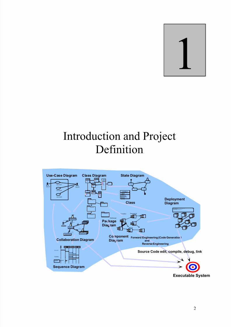
Executable System
ComponentDiagram
PackageDiagram
DeploymentDiagram
Actor A
use-case 1
use-case 2
Actor B
user :»ç¿ëÀÚ
mainWnd: MainWnd
fileMgr : FileMgr
repository : Repositorydocument: Document
gFile:GrpFile
9: sortByName ()
L1: Doc view request( )
2: fetchDoc( )
5: readDoc ()
7: readFile ( )
3: create()
6: fillDocument ( )
4: create()
8: fillFile ()
GrpFile
read( )open( )create()fillFile( )
rep
Repository
nam e : c har * = 0
readDoc( )readFile( )
(from Persistence)
FileMgr
fetchDoc()sortByName()
DocumentList
add( )delete( )
Document
nam e: intdoc id : intnum F ield: int
get()open( )close( )read( )sortFileList()create()fillDocument( )
fList
1
FileList
add( )delete( )
1
File
read()
read()fill thecode..
UI
MFC
RogueWave
global
DocumentApp
PersistenceWindow95
¹®¼-°ü¸® Ŭ¶óÀ̾ðÆ®.EXE
WindowsNT
¹®¼-°ü¸®¿£Áø.EXE
WindowsNT
Windows95
Solaris
ÀÀ¿ë¼-¹ö.EXE
AlphaUNIX
IBMMainframe
µ¥ÀÌŸº£À̽º¼-¹ö
Windows95
¹®¼-°ü¸®¾ÖÇø´
º лêȯ°æÀÇÇϵå¿þ¾î¹× ³×Æ®¿÷À¸·ÎÀÇÁ¤º¸½Ã½ºÅÛ¿¬°á¸ðµ¨-À©µµ¿ì 95: Ŭ¶óÀ̾ðÆ®-À©µµ¿ì NT: ÀÀ¿ë¼-¹ö-À ´̄нº ̧Ó½Å: ÀÀ¿ë ¼-¹ö¹× µ¥ÀÌŸ ¼-¹ö, Åë½Å ¼-¹ö- IBM¸ÞÀÎÇÁ·¹ÀÓ:µ¥ÀÌŸ¼-¹ö, Åë½Å ¼-¹ö
Document
FileManager
GraphicFileFile
Repository DocumentList
FileList
user
mainWnd fileMgr:FileMgr
repositorydocument :Document
gFile
1: Doc view request( )
2: fetchDoc( )
3: create()
4: create()
5: readDoc ()
6: fillDocument ( )
7: readFile ( )
8: fillFile ( )
9: sortByName( )
ƯÁ¤¹®¼-¿¡´ëÇѺ¸±â¸¦»ç¿ëÀÚ°¡¿äûÇÑ´Ù.
È-ÀÏ°ü¸®ÀÚ´ÂÀоî¿Â¹®¼-ÀÇÁ¤º¸¸¦ ÇØ´ç ¹®¼-°´Ã¼¿¡¼³Á¤À» ¿äûÇÑ´Ù.
È-¸é °´Ã¼´Â ÀоîµéÀÎ °´Ã¼µé¿¡´ëÇØ À̸§º°·Î Á¤·ÄÀ»½ÃÄÑÈ-¸é¿¡º¸¿©ÁØ´Ù.
Customer nameaddr
withdraw()fetch()send()
receive()
<<entity>>
Forward Engineering (Code Generation)and
Reverse Engineering
Openning
Writing
ReadingClosing
addfile[numberOffile==MAX] /flag OFF
addfile
closefile
closefile
use-case 3
Source Code edit, compile, debug, link
Use-Case Diagram Class Diagram
Collaboration Diagram
Sequence Diagram
State Diagram
Class
2
1
7/27/2019 6 SWE311 Revised Lab Manual Ultimate
http://slidepdf.com/reader/full/6-swe311-revised-lab-manual-ultimate 3/52
Software Engineering Lab Manual (ICS 413)
Lab 1: Introduction and Project Definition
Objectives
• Introduce the lab environment and tools used in the software
engineering lab: WebCT and SynchEye.
• Discuss the Project & learn how to write project definition.
1. Outline
• Getting familiar with WebCT.
• Getting familiar with SyncronEye.
• Introduction to the lab plan and objectives.
• Project definition.
2. Background
The software engineer is a key person analyzing the business, identifying
opportunities for improvement, and designing information systems to implement these
ideas. It is important to understand and develop through practice the skills needed to
successfully design and implement new software systems.
2.1 Introduction
• In this lab you will practice the software development life cycle (project
management, requirements engineering, systems modeling, software design,
prototyping, and testing) using CASE tools within a team work environment.
• UML notation is covered in this lab as the modeling language for analysis anddesign.
2.2 Tools Used in the Lab
• SWE lab is one of the most challenging of all labs. Developing a complete
software application requires from each of you a good level of know-how of
various tools.
• There are some tools which will be taught, but there are some which are
assumed you already know, if you don’t, then you learn should it individually.
o MS Source Safe: for configuration management
o MS Project: for project planning/management
o Rational Rose: for UML diagrams (object oriented analysis and design)
o Rational Requisite Pro: for software requirement specification (SRS)
documentation.
o JUnit: for testing software
2.3 Software Engineering Lab Objectives
• Learn the software life cycle phases (project management, requirements
engineering, software design, prototyping and testing).
• Practice the software phases using a project.
• Learn a number of CASE tools and use them in a project within a team work
environment.
• Get familiar with UML (modeling language for analysis and design).
3
7/27/2019 6 SWE311 Revised Lab Manual Ultimate
http://slidepdf.com/reader/full/6-swe311-revised-lab-manual-ultimate 4/52
Software Engineering Lab Manual (ICS 413)
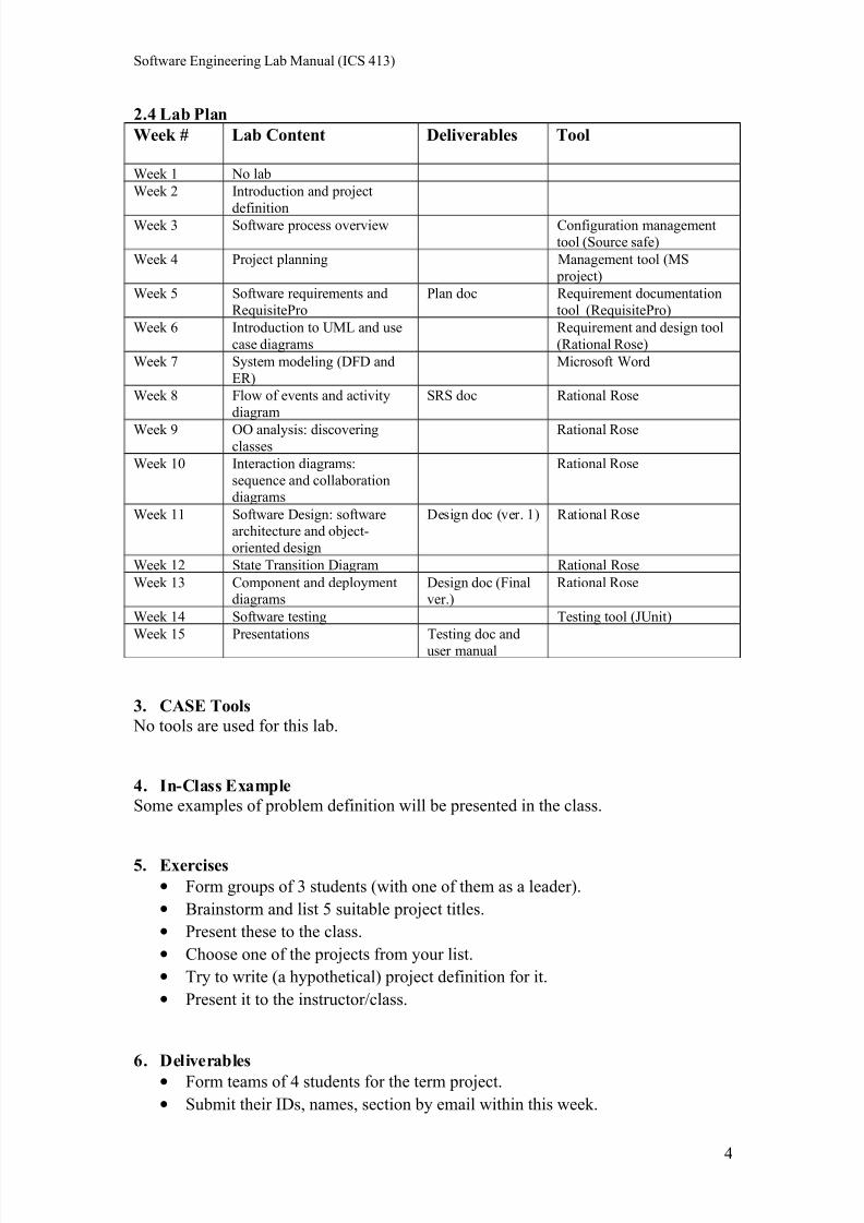
2.4 Lab Plan
Week # Lab Content Deliverables Tool
Week 1 No lab
Week 2 Introduction and project
definitionWeek 3 Software process overview Configuration management
tool (Source safe)
Week 4 Project planning Management tool (MS
project)
Week 5 Software requirements and
RequisitePro
Plan doc Requirement documentation
tool (RequisitePro)
Week 6 Introduction to UML and use
case diagrams
Requirement and design tool
(Rational Rose)
Week 7 System modeling (DFD and
ER)
Microsoft Word
Week 8 Flow of events and activity
diagram
SRS doc Rational Rose
Week 9 OO analysis: discoveringclasses
Rational Rose
Week 10 Interaction diagrams:
sequence and collaborationdiagrams
Rational Rose
Week 11 Software Design: softwarearchitecture and object-
oriented design
Design doc (ver. 1) Rational Rose
Week 12 State Transition Diagram Rational Rose
Week 13 Component and deploymentdiagrams
Design doc (Finalver.)
Rational Rose
Week 14 Software testing Testing tool (JUnit)
Week 15 Presentations Testing doc and
user manual
3. CASE Tools
No tools are used for this lab.
4. In-Class Example
Some examples of problem definition will be presented in the class.
5. Exercises
• Form groups of 3 students (with one of them as a leader).
• Brainstorm and list 5 suitable project titles.
• Present these to the class.
• Choose one of the projects from your list.
• Try to write (a hypothetical) project definition for it.
• Present it to the instructor/class.
6. Deliverables
• Form teams of 4 students for the term project.
• Submit their IDs, names, section by email within this week.
4

7/27/2019 6 SWE311 Revised Lab Manual Ultimate
http://slidepdf.com/reader/full/6-swe311-revised-lab-manual-ultimate 5/52
Software Engineering Lab Manual (ICS 413)
• Suggest / research a project and write a project definition/problem statement.
5
7/27/2019 6 SWE311 Revised Lab Manual Ultimate
http://slidepdf.com/reader/full/6-swe311-revised-lab-manual-ultimate 6/52
Software Engineering Lab Manual (ICS 413)
Software Processes andVisual Source Safe
2
6
7/27/2019 6 SWE311 Revised Lab Manual Ultimate
http://slidepdf.com/reader/full/6-swe311-revised-lab-manual-ultimate 7/52
Software Engineering Lab Manual (ICS 413)
Lab 2: Software Processes and Visual Source Safe
Objectives
• Obtain a deeper understanding of software process models and software
processes.
• Become familiar with a configuration management case tool (Microsoft
Visual Source Safe).
1. Outline
• Review of the basic software process models and software processes.
• Visual Source Safe tutorial.
2. Background
IEEE defined a software process as: “a set of activities, practices and transformationsthat people use to develop and maintain software and the associated products, e.g.,
project plans, design documents, code, test cases and user manual”.
Following the software process will stabilize the development lifecycle and make the
software more manageable and predictable. It will also reduce software development
risk and help to organize the work products that need to be produced during a
software development project. A well-managed process will produce high quality
products on time and under budget. So following a mature software process is a key
determinant to the success of a software project.
A number of software processes are available. However, no single software process
works well for every project. Each process works best in certain environments
Examples of the available software process models include: the Waterfall model (the
Linear model), the evolutionary development, the formal systems development, and
reuse-based (component-based) development. Other process models support iteration;
these include: the Incremental model, the Spiral model, and Extreme Programming.
3. CASE Tools
Visual Source Safe (VSS) is Microsoft's version of a source control program
(configuration management) that enables you to keep track of multiple versions of documents.
Software Configuration Management is a set of activities that have been developed to
manage change throughout the life of computer software. These activities are
designed to control change by identifying the work products that are likely to change,
establishing relationships among them, defining mechanisms for managing different
versions of these work products, controlling the changes imposed and auditing the
reporting on the changes made.
With VSS you can go back to an earlier bug-free version of the source code to try to
track down where the bug was introduced, compare versions of a document andrecover a copy of the document that you saved weeks or months ago.
7
7/27/2019 6 SWE311 Revised Lab Manual Ultimate
http://slidepdf.com/reader/full/6-swe311-revised-lab-manual-ultimate 8/52
Software Engineering Lab Manual (ICS 413)
3.1 How Does It Work?
In order for Visual Source Safe to manage your documents, you must first check them
in to VSS. When you first check a file in to VSS, the program records the contents of
this original version. The document then becomes read-only to prevent you from
making changes that VSS cannot track. When you want to edit a document that is
under source control, you must check the document out of VSS to get a writable copy.When you are finished editing the document, you save the document and then check it
back in to VSS. VSS will then contain two "versions" of the document: the original
and the new edit. In reality, VSS does not keep two full copies. It keeps the original
document, and a small file describing the differences between the original and the
edited version. If you edit the document 100 times over the course of a year, you will
have access to all 100 versions in VSS, without having to use all of the disk space that
100 copies of the document would occupy.
3.2 Why Is It Useful?
VSS lets you view any version of your document, or check out any version for further
editing. It also lets you pick any two versions-- say, draft 6 and draft 31-- andcompare them with the Diff utility. This comparison shows the two documents side by
side, with the differences highlighted and color-coded. VSS also enables you to attach
comments to each revision; these comments may or may not appear in the document
itself, depending on how you configure the program. But the comments can be viewed
independently of the documents themselves.
Another very useful feature of VSS is labeling. Labeling provides a simple way of
knowing which versions of which documents belong together in a group. VSS was
designed for environments in which multiple users are editing the same documents. It
permits only one user at a time to edit each document, thereby guaranteeing that only
one authoritative "latest version" of a document exists at any given time.
4. In-Class Demo
A demonstration will be given show the basic functions of VSS in order to manage
your files. These features include:
a. Creating a new project.
b. Checking files in and out.
c. Labeling files.
d. Viewing revision history.
e. Using Diff to show differences.f. Using Search to find documents.
For more information on software processes and VSS tutorial please refer to Lab 2
slides which contain an overview of software processes and VSS tutorial slides.
5. Exercises
• Create a project and add some java files to it (at least 3 files).
• Label the existing files.
• Check out all the files and modify one of them.
• Check the edited file back in.
• View the revision history of the edited file and show the differences between
the old and the new versions.
8
7/27/2019 6 SWE311 Revised Lab Manual Ultimate
http://slidepdf.com/reader/full/6-swe311-revised-lab-manual-ultimate 9/52
Software Engineering Lab Manual (ICS 413)
• Search for any unchecked in files.
After you perform all of the previous tasks, create a new project for your term project.
If any files of your term project are ready, you need to check them in. You need to
manage all your term project files using Source Safe.
6. Deliverables
You should successfully demonstrate that all the exercise tasks were implemented.
Also your VSS project for your term project should be created and any available files
should be checked in.
9
7/27/2019 6 SWE311 Revised Lab Manual Ultimate
http://slidepdf.com/reader/full/6-swe311-revised-lab-manual-ultimate 10/52
Software Engineering Lab Manual (ICS 413)
Project Planning and
Management
3
10
7/27/2019 6 SWE311 Revised Lab Manual Ultimate
http://slidepdf.com/reader/full/6-swe311-revised-lab-manual-ultimate 11/52
Software Engineering Lab Manual (ICS 413)
Lab 3: Project Planning and Management
Objectives
• Gain understanding of project management.
•
Learn how to prepare project plans.• Learn about project risks.
• Learn MS Project case tool.
1. Outline
• Project work planning.
• Risk management.
• MS project.
• Examples.
2. Background
Project management is the process of planning and controlling the development of a
system within a specified timeframe at a minimum cost with the right functionality.
2.1 Project Work Plan
Prepare a list of all tasks in the work breakdown structure, plus:
• Duration of task.
• Current task status.
• Task dependencies.
• Key milestone dates.
2.2 Tracking Progress
• Gantt Chart:
o Bar chart format.
o Useful to monitor project status at any point in time.
• PERT Chart:
o Flowchart format.
o Illustrate task dependencies and critical path.
2.3 Risk Management
• Risk management is concerned with identifying risks and drawing up plans to
minimize their effect on a project.
• A risk is a probability that some adverse circumstance will occur.
• Project risks which affect schedule or resources.
• Product risks which affect the quality or performance of the software being
developed.
• Business risks which affect the organization developing the software.
2.4 Risk Management Process
• Risk identification: identify project, product and business risks.
• Risk analysis: assess the likelihood and consequences of these risks.
11
7/27/2019 6 SWE311 Revised Lab Manual Ultimate
http://slidepdf.com/reader/full/6-swe311-revised-lab-manual-ultimate 12/52
Software Engineering Lab Manual (ICS 413)
• Risk planning: draw up plans to avoid or minimize the effects of the risk.
• Risk monitoring: monitor the risks throughout the project.
3. CASE Tools
• Microsoft Project is the clear market leader among desktop project
management applications.
• Primavera Project Planner: multi-project, multi-user project, and resource
planning and scheduling.
• SureTrak Project Manager: resource planning and control for small-to-medium
sized projects.
• According to the Gartner Group, it accounts for about two-thirds of all project
management software sales.
MS Project Jump Start Live Demo
4. In-Class Demo Now you will learn how to apply the above mentioned methods to draw a Gantt chart
or Activity chart for the project. Please refer to Lab 3 slides which explain the process
in detail with some examples.
5. Exercises
Use MS Project 2002 to create a series of tasks leading to completion of a project of
your choice.
For your project, you need to:
• Set start or ending dates.
• Develop a list of tasks that need to be completed.
• Establish any sub tasks and create links.
• Create any links between major tasks.
• Assign a specific amount time for each task.
• Assign resources for each task.
• Create task information for each item you put into the list.
6. Deliverables
You should submit the solutions for the previous exercises.
You should use MS Project to create a plan and time schedule for your term project.
12
7/27/2019 6 SWE311 Revised Lab Manual Ultimate
http://slidepdf.com/reader/full/6-swe311-revised-lab-manual-ultimate 13/52
Software Engineering Lab Manual (ICS 413)
Software RequirementSpecification (SRS)
4
13
7/27/2019 6 SWE311 Revised Lab Manual Ultimate
http://slidepdf.com/reader/full/6-swe311-revised-lab-manual-ultimate 14/52
Software Engineering Lab Manual (ICS 413)
Lab 4: Software Requirement Specification (SRS)
Objectives
• Gain a deeper understanding of the Software Requirement Specification
phase and the Software Requirement Specification (SRS).
• Learn how to write requirements and specifications.
• Gain exposure to requirements management using RequisitePro.
1. Outline
• Review of the requirements engineering process.
• Write requirements and specifications.
• RequisitePro tutorial.
• Software Requirement Specification (SRS).
2. Background
A requirement is a statement of a behavior or attribute that a system must possess for
the system to be acceptable to a stakeholder.
Software Requirement Specification (SRS) is a document that describes the
requirements of a computer system from the user's point of view. An SRS document
specifies:
• The required behavior of a system in terms of: input data, required processing,
output data, operational scenarios and interfaces.
• The attributes of a system including: performance, security, maintainability,
reliability, availability, safety requirements and design constraints.
Requirements management is a systematic approach to eliciting, organizing and
documenting the requirements of a system. It is a process that establishes and
maintains agreement between the customer and the project team on the changing
requirements of a system.
Requirements management is important because, by organizing and tracking the
requirements and managing the requirement changes, you improve the chances of
completing the project on time and under budget. Poor change management is a key
cause of project failure.
2.1 Requirements Engineering Process
Requirements engineering process consists of four phases:
• Requirements elicitation: getting the customers to state exactly what the
requirements are.
• Requirements analysis: making qualitative judgments and checking for
consistency and feasibility of requirements.
• Requirements validation: demonstrating that the requirements define the
system that the customer really wants.
• Requirements management: the process of managing changing requirements
during the requirements engineering process and system development, andidentifying missing and extra requirements.
14
7/27/2019 6 SWE311 Revised Lab Manual Ultimate
http://slidepdf.com/reader/full/6-swe311-revised-lab-manual-ultimate 15/52
Software Engineering Lab Manual (ICS 413)
2.2 Writing Requirements
Requirements always need to be correct, unambiguous, complete, consistent, and
testable.
2.2.1 Recommendations When Writing Requirements
• Never assume: others do now know what you have in mind.• Use meaningful words; avoid words like: process, manage, perform, handle,
and support.
• State requirements not features:
o Feature: general, tested only for existence.
o Requirement: specific, testable, measurable.
• Avoid:
o Conjunctions: ask yourself whether the requirement should it be split
into two requirements.
o Conditionals: if, else, but, except, although.
o Possibilities: may, might, probably, usually.
2.3 Writing Specifications
Specification is a description of operations and attributes of a system. It can be a
document, set of documents, a database of design information, a prototype, diagrams
or any combination of these things.
Specifications are different from requirements: specifications are sufficiently
complete ─ not only what stakeholders say they want; usually, they have no conflicts;
they describe the system as it will be built and resolve any conflicting requirements.
Creating specifications is important. However, you may not create specifications if:
• You are using a very incremental development process (small changes).
• You are building research or proof of concept projects.
• You rebuilding very small projects.
• It is not cheaper or faster than building the product.
2.4 Software Requirement Specification (SRS)
Remember that there is no “Perfect SRS”. However, SRS should be:
• Correct: each requirement represents something required by the target system.
• Unambiguous: every requirement in SRS has only one interpretation
• Complete: everything the target system should do is included in SRS (no
sections are marked TBD-to be determined).
• Verifiable: there exists some finite process with which a person/machine can
check that the actual as-built software product meets the requirements.
• Consistent in behavior and terms.
• Understandable by customers.
• Modifiable: changes can be made easily, completely and consistently.
• Design independent: doesn't imply specific software architecture or algorithm.
• Concise: shorter is better.
•
Organized: requirements in SRS are easy to locate; related requirements aretogether.
15
7/27/2019 6 SWE311 Revised Lab Manual Ultimate
http://slidepdf.com/reader/full/6-swe311-revised-lab-manual-ultimate 16/52
Software Engineering Lab Manual (ICS 413)
• Traceable: each requirement is able to be referenced for later use (by the using
paragraph numbers, one requirement in each paragraph, or by using
convention for indication requirements)
16
7/27/2019 6 SWE311 Revised Lab Manual Ultimate
http://slidepdf.com/reader/full/6-swe311-revised-lab-manual-ultimate 17/52
Software Engineering Lab Manual (ICS 413)
3. CASE Tools
RequisitePro is a powerful, easy-to-use requirements management tool that helps
teams manage project requirements comprehensively, promotes communication and
collaboration among team members, and reduces project risk. It thereby increases the
chances of delivering a product that the client wants and does so in a timely manner.
RequisitePro offers the power of a database and Microsoft Word and is integrated
with other Rational Suite products.
4. In-Class Demo
An overview of the basic features of RequisitePro will be presented. In the exercise
section you will practice and apply what you have learned in the tutorial. Please refer
to lab 4 slides which contain a tutorial on RequisitePro and an overview of the
requirements engineering process, and writing requirements and specifications.
5. Exercises
a. Are the following requirements vague? If yes, why? Can you fix them?
o The feature is responsible for managing connections.
o The feature allows users to perform administrative functions.
b. Perform each of the following tasks using RequisitePro:
o Create a new project.
o Create a new package.
o Create and add some requirements within RequisitePro.
o Create a requirement document.o Create a new view.
6. Deliverables
• You should submit the solutions for exercise 5.a.
• You should show that you have successfully performed all the tasks listed in
exercise 5.b.
• Also during the requirement phase of your term project, you should use
RequisitePro to manage your requirements.
17
7/27/2019 6 SWE311 Revised Lab Manual Ultimate
http://slidepdf.com/reader/full/6-swe311-revised-lab-manual-ultimate 18/52
Software Engineering Lab Manual (ICS 413)
Introduction to UML and Use
Case Diagram
5
18
7/27/2019 6 SWE311 Revised Lab Manual Ultimate
http://slidepdf.com/reader/full/6-swe311-revised-lab-manual-ultimate 19/52
Software Engineering Lab Manual (ICS 413)
Lab 5: Introduction to UML and Use Case Diagram
Objectives
• Study the benefits of visual modeling.
• Learn use case diagrams: discovering actors and discovering use cases.
• Practice use cases diagrams using Rational Rose.
1. Outline
• Visual modeling.
• Introduction to UML.
• Introduction to visual modeling with UML.
• Use case diagrams: discovering actors and use cases.
2. BackgroundVisual Modeling is a way of thinking about problems using models organized around
real-world ideas. Models are useful for understanding problems, communicating with
everyone involved with the project (customers, domain experts, analysts, designers,
etc.), modeling enterprises, preparing documentation, and designing programs and
databases
2.1 Visual Modeling
• Capture the structure and behavior of architectures and components.
• Show how the elements of the system fit together.
•Hide or expose details appropriate for the task.
• Maintain consistency between a design and its implementation.
• Promote unambiguous communication.
2.2 What is UML?
The UML is the standard language for visualizing, specifying, constructing and
documenting the artifacts of a software-intensive system. UML can be used with all
processes throughout the development life cycle and across different implementation
technologies.
2.3 History of UML
The UML is an attempt to standardize the artifacts of analysis and design: semanticmodels, syntactic notation and diagrams. The first public draft (version 0.8) was
introduced in October 1995. Feedback from the public and Ivar Jacobson's input were
included in the next two versions (0.9 in July 1996 and 0.91 in October 1996).
Version 1.0 was presented to the Object Management Group (OMG) for
standardization in July 1997. Additional enhancements were incorporated into the 1.1
version of UML, which was presented to the OMG in September 1997. In November
1997, the UML was adopted as the standard modeling language by the OMG.
2.4 Putting UML into Work: Use Case Diagram
The behavior of the system under development (i.e. what functionality must be
provided by the system) is documented in a use case model that illustrates thesystem's intended functions (use cases), its surroundings (actors), and relationships
between the use cases and actors (use case diagrams).
19
7/27/2019 6 SWE311 Revised Lab Manual Ultimate
http://slidepdf.com/reader/full/6-swe311-revised-lab-manual-ultimate 20/52
Software Engineering Lab Manual (ICS 413)
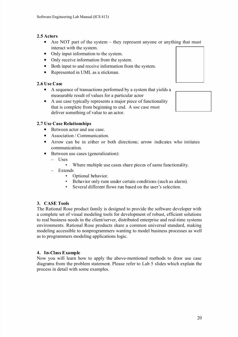
2.5 Actors
• Are NOT part of the system – they represent anyone or anything that must
interact with the system.
• Only input information to the system.
• Only receive information from the system.• Both input to and receive information from the system.
• Represented in UML as a stickman.
2.6 Use Case
• A sequence of transactions performed by a system that yields a
measurable result of values for a particular actor
• A use case typically represents a major piece of functionality
that is complete from beginning to end. A use case must
deliver something of value to an actor.
2.7 Use Case Relationships
• Between actor and use case.
• Association / Communication.
• Arrow can be in either or both directions; arrow indicates who initiates
communication.
• Between use cases (generalization):
– Uses
• Where multiple use cases share pieces of same functionality.
– Extends
• Optional behavior.• Behavior only runs under certain conditions (such as alarm).
• Several different flows run based on the user’s selection.
3. CASE Tools
The Rational Rose product family is designed to provide the software developer with
a complete set of visual modeling tools for development of robust, efficient solutions
to real business needs in the client/server, distributed enterprise and real-time systems
environments. Rational Rose products share a common universal standard, making
modeling accessible to nonprogrammers wanting to model business processes as well
as to programmers modeling applications logic.
4. In-Class Example
Now you will learn how to apply the above-mentioned methods to draw use case
diagrams from the problem statement. Please refer to Lab 5 slides which explain the
process in detail with some examples.
20
7/27/2019 6 SWE311 Revised Lab Manual Ultimate
http://slidepdf.com/reader/full/6-swe311-revised-lab-manual-ultimate 21/52
Software Engineering Lab Manual (ICS 413)
5. Exercises
Read carefully the following problem statement
We are after a system that controls a recycling machine for returnable bottles and
cans. The machine will allow a customer to return bottles or cans on the same
occasion.
When the customer returns an item, the system will check what type has been
returned. The system will register how many items each customer returns and, when
the customer asks for a receipt, the system will print out what he deposited, the value
of the returned items and the total return sum that will be paid to the customer.
The system is also be used by an operator. The operator wants to know how many
items of each type have been returned during the day. At the end of the day, the
operator asks for a printout of the total number of items that have been deposited in
the machine on that particular day. The operator should also be able to change
information in the system, such as the deposit values of the items. If something is
amiss, for example if a can gets stuck or if the receipt roll is finished, the operator will be called by a special alarm signal.
After reading the above problem statement, find:
1. Actors
2. Use cases with each actor
3. Find extended or uses use cases (if applicable)
4. Finally : draw the main use case diagram:
6. Deliverables
You should submit the solutions for the previous exercises.
You should use these techniques to draw use case diagrams for your term project
using Rational Rose.
21
7/27/2019 6 SWE311 Revised Lab Manual Ultimate
http://slidepdf.com/reader/full/6-swe311-revised-lab-manual-ultimate 22/52
Software Engineering Lab Manual (ICS 413)
System Modeling
6
22
7/27/2019 6 SWE311 Revised Lab Manual Ultimate
http://slidepdf.com/reader/full/6-swe311-revised-lab-manual-ultimate 23/52
Software Engineering Lab Manual (ICS 413)
Lab 6: System Modeling
Objective:
Deeper understanding of System modeling:
• Data model: entity-relationship diagram (ERD).
• Functional model: data flow diagram (DFD).
1. Outline
System analysis model elements:
• Data model: entity-relationship diagram (ERD)
• Functional model: data flow diagram (DFD)
2. Background
Modeling consists of building an abstraction of reality. These abstractions aresimplifications because they ignore irrelevant details and they only represent the
relevant details (what is relevant or irrelevant depends on the purpose of the model).
2.1 Why Model Software?
Software is getting larger, not smaller; for example, Windows XP has more than 40
million lines of code. A single programmer cannot manage this amount of code in its
entirety. Code is often not directly understandable by developers who did not
participate in the development; thus, we need simpler representations for complex
systems (modeling is a mean for dealing with complexity).
A wide variety of models have been in use within various engineering disciplines for
a long time. In software engineering a number of modeling methods are also
available.
2.2 Analysis Model Objectives
• To describe what the customer requires.
• To establish a basis for the creation of a software design.
• To define a set of requirements that can be validated once the software is built.
2.3 The Elements of the Analysis Model
The generic analysis model consists of:• An entity-relationship diagram (data model).
• A data flow diagram (functional model).
• A state transition diagram (behavioral model).
NOTE: state transition diagram will be covered in lab 11.
23
7/27/2019 6 SWE311 Revised Lab Manual Ultimate
http://slidepdf.com/reader/full/6-swe311-revised-lab-manual-ultimate 24/52
Software Engineering Lab Manual (ICS 413)
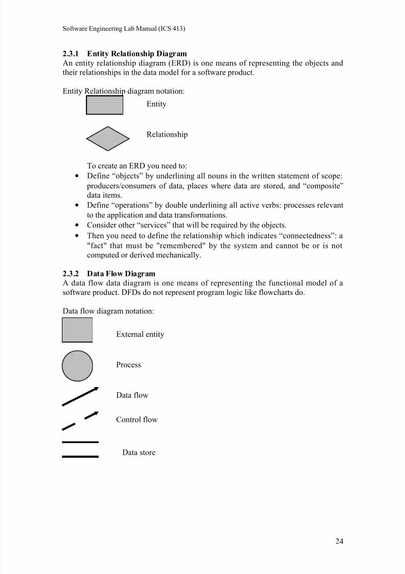
2.3.1 Entity Relationship Diagram
An entity relationship diagram (ERD) is one means of representing the objects and
their relationships in the data model for a software product.
Entity Relationship diagram notation:
To create an ERD you need to:
• Define “objects” by underlining all nouns in the written statement of scope:
producers/consumers of data, places where data are stored, and “composite”
data items.
• Define “operations” by double underlining all active verbs: processes relevant
to the application and data transformations.
• Consider other “services” that will be required by the objects.
• Then you need to define the relationship which indicates “connectedness”: a
"fact" that must be "remembered" by the system and cannot be or is not
computed or derived mechanically.
2.3.2 Data Flow Diagram
A data flow data diagram is one means of representing the functional model of a
software product. DFDs do not represent program logic like flowcharts do.
Data flow diagram notation:
Entity
Relationship
External entity
Process
Data flow
Control flow
Data store
24
7/27/2019 6 SWE311 Revised Lab Manual Ultimate
http://slidepdf.com/reader/full/6-swe311-revised-lab-manual-ultimate 25/52
Software Engineering Lab Manual (ICS 413)
To create a DFD you need to:
• Review ERD to isolate data objects and grammatical parse to determine
operations.
• Determine external entities (producers and consumers of data).
• Create a level 0 DFD “Context Diagram” (one single process).
• Balance the flow to maintain data flow continuity.
• Develop a level 1 DFD; use a 1:5 (approx.) expansion ratio.
Data Flow Diagram Guidelines:
• All icons must be labeled with meaningful names.
• Always show external entities at level 0.
• Always label data flow arrows.
• Do not represent procedural logic.
• Each bubble is refined until it does just one thing.
3. CASE Tools
You can use MS word to create your ERD and DFD since we do not have a license
for a case tool that supports these diagrams.
4. In-Class Example
Now you will learn how to create ERD and DFD. Please refer to Lab 6 slides which
explain the process of creating ERD and DFD with some examples.
5. Exercises
a. Create an ERD for an airline reservation system.
b. Create a DFD for:
i. Student Registration System.
ii. (a + b) * ( c + a * d)
6. Deliverables
You should submit the solutions for the previous exercises.
You should create ERD and DFD for your term project if needed. You also need tocheck them into Source Safe.
25
7/27/2019 6 SWE311 Revised Lab Manual Ultimate
http://slidepdf.com/reader/full/6-swe311-revised-lab-manual-ultimate 26/52
Software Engineering Lab Manual (ICS 413)
Documenting Use Cases and
Activity Diagrams
7
26
7/27/2019 6 SWE311 Revised Lab Manual Ultimate
http://slidepdf.com/reader/full/6-swe311-revised-lab-manual-ultimate 27/52
Software Engineering Lab Manual (ICS 413)
Lab 7: Documenting Use Cases and Activity Diagrams
Objectives
• Study how to document use cases in detail.
•
Know about scenarios (flow of events) and its importance.• Deeper understanding of UML activity diagrams.
• Practicing flow of events and activity diagrams using Rational Rose.
1. Outline
• Writing flow of events.
• Flow of events template and example.
• Activity diagrams.
• Examples.
2. Background
Each use case is documented with a flow of events. The flow of events for a use case
is a description of the events needed to accomplish the required behavior of the use
case. Activity diagrams may also be created at this stage in the life cycle. These
diagrams represent the dynamics of the system. They are flow charts that are used to
show the workflow of a system; that is, they show the flow of control from one
activity to another in the system,
2.1 Flow of Events
A description of events required to accomplish the behavior of the use case, that:• Show WHAT the system should do, not HOW the system does it.
• Written in the language of the domain, not in terms of implementation.
• Written from an actor point of view.
A flow of events document is created for each use case:
• Actors are examined to determine how they interact with the system.
• Break down into the most atomic actions possible.
2.2 Contents of Flow of Events
• When and how the use case starts and ends.
• What interaction the use case has with the actors.• What data is needed by the use case.
• The normal sequence of events for the use case.
• The description of any alternate or exceptional flows.
2.3 Template for the flow of events document
Each project should use a standard template for the creation of the flow of events
document. The following template seems to be useful.
X Flow of events for the <name> use case
X.1 Preconditions
X.2 Main flow
X.3 Sub-flows (if applicable)
X.4 Alternative flows
where X is a number from 1 to the number of use cases.
27
7/27/2019 6 SWE311 Revised Lab Manual Ultimate
http://slidepdf.com/reader/full/6-swe311-revised-lab-manual-ultimate 28/52
Software Engineering Lab Manual (ICS 413)
A sample completed flow of events document for the Select Courses to Teach use
case follows.
1. Flow of Events for the Select Courses to Teach Use Case
1.1 PreconditionsCreate course offerings sub-flow of the maintain course information use case must
execute before this use case begins.
1.2 Main Flow
This use case begins when the professor logs onto the registration system and enters
his/her password. The system verifies that the password is valid (E-1) and prompts the
professor to select the current semester or a future semester (E-2). The professor
enters the desired semester. The system prompts the Professor to select the desired
activity: ADD, DELETE, REVIEW, PRINT, or QUIT.
If the activity selected is ADD, the S-1: add a course offering sub-flow is performed.
If the activity selected is DELETE, the S-2: delete a course offering sub-flow is
performed.
If the activity selected is REVIEW, the S-3: review schedule sub-flow is performed.
If the activity selected is PRINT, the S-4: print a schedule sub-flow is performed.
If the activity selected is QUIT, the use case ends.
1.3 Sub-flows
S-1: Add a Course Offering:
The system displays the course screen containing a field for a course name and
number. The professor enters the name and number of a course (E-3). The system
displays the course offerings for the entered course (E-4). The professor selects a
course offering. The system links the professor to the selected course offering (E-5).
The use case then begins again.
S-2: Delete a Course Offering:
The system displays the course offering screen containing a field for a course offering
name and number. The professor enters the name and number of a course offering (E-6). The system removes the link to the professor (E-7). The use case then begins
again.
S-3: Review a Schedule:
The system retrieves (E-8) and displays the following information for all course
offerings for which the professor is assigned: course name, course number, course
offering number, days of the week, time, and location. When the professor indicates
that he or she is through reviewing, the use case begins again.
S-4: Print a Schedule
The system prints the professor schedule (E-9). The use case begins again.
28
7/27/2019 6 SWE311 Revised Lab Manual Ultimate
http://slidepdf.com/reader/full/6-swe311-revised-lab-manual-ultimate 29/52
Software Engineering Lab Manual (ICS 413)
1.4 Alternative Flows
E-1: An invalid professor ID number is entered. The user can re-enter a professor ID
number or terminate the use case.
E-2: An invalid semester is entered. The user can re-enter the semester or terminate
the use case.
E-3: An invalid course name/number is entered. The user can re-enter a valid
name/number combination or terminate the use case.
E-4: Course offerings cannot be displayed. The user is informed that this option is not
available at the current time. The use case begins again.
E-5: A link between the professor and the course offering cannot be created. The
information is saved and the system will create the link at a later time. The use case
continues.
E-6: An invalid course offering name/number is entered. The user can re-enter a valid
course offering name/number combination or terminate the use case.
E-7: A link between the professor and the course offering cannot be removed. The
information is saved and the system will remove the link at a later time. The use case
continues.
E-8: The system cannot retrieve schedule information. The use case then begins again.
E-9: The schedule cannot be printed. The user is informed that this option is not
available at the current time. The use case begins again.
Use case flow of events documents are entered and maintained in documents external
to Rational Rose. The documents are linked to the use case.
2.4 Activity Diagrams
Activity diagrams are flow charts that are used to show the workflow of a system.
They also:
• Represent the dynamics of the system.
• Show the flow of control from activity to activity in the system.
• Show what activities can be done in parallel, and any alternate paths through
the flow.Activity diagrams may be created to represent the flow across use cases or they may
be created to represent the flow within a particular use case. Later in the life cycle,
activity diagrams may be created to show the workflow for an operation.
2.5 Activity Diagram Notation
• Activities- performance of some behavior in the workflow.
• Transition- passing the flow of control from activity to activity.
• Decision- show where the flow of control branches based on a decision point:
o Guard condition is used to determine which path from the decision
point is taken.• Synchronization-what activities are done concurrently? What activities must
be completed before processing may continue (join).
29
7/27/2019 6 SWE311 Revised Lab Manual Ultimate
http://slidepdf.com/reader/full/6-swe311-revised-lab-manual-ultimate 30/52
Software Engineering Lab Manual (ICS 413)
3. CASE Tools
Rational Rose (introduced in lab 5).
4. In-Class Example Now you will learn how to apply the above mentioned methods to write flow of
events and drawing activity diagrams from the use case(s) flow of events. Please refer
to Lab 7 slides which explain the process in detail with some examples.
5. Exercises
1. Take two of the use cases from recycling machine problem (Lab 5) and write
flow of events for those. You should work in groups of three to solve this
problem.
2. Practice activity diagram from the example in PPT (Lab 7) for course catalog
creation.
6. Deliverables
You should submit the solutions for the previous exercises.
You should use these techniques to write flow of events and draw activity diagrams
for your term project.
30

7/27/2019 6 SWE311 Revised Lab Manual Ultimate
http://slidepdf.com/reader/full/6-swe311-revised-lab-manual-ultimate 31/52
Software Engineering Lab Manual (ICS 413)
Object Oriented Analysis:Discovering Classes
8
31
7/27/2019 6 SWE311 Revised Lab Manual Ultimate
http://slidepdf.com/reader/full/6-swe311-revised-lab-manual-ultimate 32/52
Software Engineering Lab Manual (ICS 413)
Lab 8: Object-Oriented Analysis: Discovering Classes
Objective
• Learn the object-oriented analysis phase by understanding the methods
of class elicitation and finding the classes in an object-oriented system.
1. Outline
• Object-Oriented concepts
• Discovering classes’ approaches: noun phrase approach, common class
patterns, use case driven method, CRC (Class-Responsibility-Collaboration)
and mixed approach.
• Examples.
2. BackgroundClasses: a description of a group of objects with common properties (attributes),
common behavior (operations), common relationships to other objects and common
semantics.
2.1 Object-Oriented Concepts
• Attribute: the basic data of the class.
• Method (operation): an executable procedure that is encapsulated in a class
and is designed to operate on one or more data attributes that are defined as
part of the class.
•Object: when specific values are assigned to all the resources defined in aclass, the result is an instance of that class. Any instance of any class is called
an object.
2.2 Discovering Classes
Discovering and defining classes to describe the structure of a computerized system is
not an easy task. When the problem domain is new or unfamiliar to the software
developers it can be difficult to discover classes; a cookbook for finding classes does
not exist.
2.3 Classes Categories
Classes are divided into three categories:• Entity: models information and associated behavior that is long-lived, independent
of the surrounding, application independent, and accomplishes some responsibility
• Boundary: handles the communication between the system surroundings and the
inside of the system, provides interface, and facilitates communication with other
systems
• Control: model sequencing behavior specific to one or more use cases. Control
classes coordinate the events needed to realize the behavior specified in the use
case, and they are responsible for the flow of events in the use case.
32
7/27/2019 6 SWE311 Revised Lab Manual Ultimate
http://slidepdf.com/reader/full/6-swe311-revised-lab-manual-ultimate 33/52
Software Engineering Lab Manual (ICS 413)
2.4 Discovering Classes Approaches
Methods of discovering classes:
2.4.1 Noun Phrase Approach: Examine the requirements and underline each noun.
Each noun is a candidate class; divide the list of candidate classes into:
• Relevant classes: part of the application domain; occur frequently inrequirements.
• Irrelevant classes: outside of application domain
• Fuzzy classes: unable to be declared relevant with confidence; require
additional analysis
2.4.2 Common Class Patterns: Derives candidate classes from the classification
theory of objects; candidate classes and objects come from one of the
following sources:
• Tangible things: e.g. buildings, cars.
•Roles: e.g. teachers, students.
• Events: things that happen at a given date and time, or as steps in an
ordered sequence: e.g. landing, request, interrupt.
• Interactions: e.g. meeting, discussion.
• Sources, facilities: e.g. departments.
• Other systems: external systems with which the application interacts.
• Concept class: a notion shared by a large community.
• Organization class: a collection or group within the domain.
• People class: roles people can play.
• Places class: a physical location relevant to the system.
2.4.3 Use Case Driven Method: The scenarios - use cases that are fundamental to
the system operation are enumerated. Going over each scenario leads to the
identification of the objects, the responsibilities of each object, and how these
objects collaborate with other objects.
2.4.4 CRC (Class-Responsibility-Collaboration): Used primarily as a
brainstorming tool for analysis and design. CRC identifies classes by
analyzing how objects collaborate to perform business functions (use cases).
A CRC card contains: name of the class, responsibilities of the class and
collaborators of the class. Record name of class at the top; record
responsibilities down the left-hand side; record other classes (collaborators)
that may be required to fulfill each responsibility on the right-hand side.
CRC cards are effective at analyzing scenarios; they force you to be concise
and clear; they are cheap, portable and readily available.
2.4.5 Mixed Approach: A mix of these approaches can be used, one possible
scenario is:
• Use CRC for brainstorming.
• Identify the initial classes by domain knowledge.
• Use common class patterns approach to guide the identification of the
classes.• Use noun phrase approach to add more classes.
• Use the use case approach to verify the identified classes.
33
7/27/2019 6 SWE311 Revised Lab Manual Ultimate
http://slidepdf.com/reader/full/6-swe311-revised-lab-manual-ultimate 34/52
Software Engineering Lab Manual (ICS 413)
2.5 Class Elicitation Guidelines
• A class should have a single major role.
• A class should have defined responsibilities (use CRC cards if needed).
• Classes should be of a manageable size: if a class has too many attributes
or operations, consider splitting it.
• A class should have a well-defined behavior, preferably by implementing a
given requirement or an interface.
3. CASE Tools
Rational Rose (introduced in lab 7).
4. In-Class Example
Now you will learn how to apply the above mentioned methods of finding classesfrom the problem statement. Please refer to Lab 8 slides which explain the process of
finding classes with some examples.
5. Exercises
Consider the following requirements for the Video Store system. Identify the
candidate classes:
The video store keeps in stock an extensive library of current and popular movie
titles. A particular movie may be held on video tape or disk.
Video tapes are in either "Beta" or "VHS" format. Video disks are in DVD format.
Each movie has a particular rental period (expressed in days), with a rental charge tothat period. The video store must be able to immediately answer any inquiries about a
movie's stock availability and how many tapes and/or disks are available for rental.
The current condition of each tape and disk must be known and recorded.
The rental charge differs depending on video medium: tape or disk (but it is the same
for the two categories of tapes: Beta and VHS).
The system should accommodate future video storage formats in addition to VHS
tapes, Beta tapes and DVD disks. The employees frequently use a movie code, instead
of movie title, to identify the movie. The same movie title may have more than one
release by different directors.
You may use any (or mix) of the class elicitation methods to find the candidateclasses.
6. Deliverables
• You should submit the solutions for the previous exercises.
• Also you should use these class elicitation techniques to identify the classes
for your term project.
34
7/27/2019 6 SWE311 Revised Lab Manual Ultimate
http://slidepdf.com/reader/full/6-swe311-revised-lab-manual-ultimate 35/52
Software Engineering Lab Manual (ICS 413)
Interaction Diagrams: Sequence
& Collaboration Diagrams
9
35
7/27/2019 6 SWE311 Revised Lab Manual Ultimate
http://slidepdf.com/reader/full/6-swe311-revised-lab-manual-ultimate 36/52
Software Engineering Lab Manual (ICS 413)
Lab 9: Interaction Diagrams: Sequence & Collaboration
Diagrams
Objectives
•Better understanding of the interaction diagrams.
• Get familiar with sequence & collaboration diagrams.
• Practice drawing the interaction diagrams using Rational Rose.
1. Outline
• Interaction diagrams:
o Sequence diagrams
o Collaboration diagrams
2. Background
Interaction diagrams describe how groups of objects collaborate in some behavior. An
interaction diagram typically captures the behavior of a single use case.
Interaction diagrams do not capture the complete behavior, only typical scenarios.
2.1 Analyzing a System’s Behavior
UML offers two diagrams to model the dynamics of the system: sequence and
collaboration diagrams. These diagrams show the interactions between objects.
2.2 Sequence Diagrams
Sequence diagrams are a graphical way to illustrate a scenario:• They are called sequence diagrams because they show the sequence of
message passing between objects.
• Another big advantage of these diagrams is that they show when the objects
are created and when they are destructed. They also show whether messages
are synchronous or asynchronous
2.3 Creating Sequence Diagrams
• You must know the scenario you want to model before diagramming sequence
diagrams.
• After that specify the classes involved in that scenario.
• List the involved objects in the scenario horizontally on the top of the page.
• Drop a dotted line beneath every object. They are called lifelines.
• The scenario should start by a message pass from the first object.
• You must know how to place the objects so that the sequence is clear.
• You may start the scenario by an actor.
• Timing is represented vertically downward.
• Arrows between life lines represents message passing.
• Horizontal arrows may pass through the lifeline of another object, but must
stop at some other object.
•
You may add constraints to these horizontal arrows.• Objects may send messages to themselves.
36

7/27/2019 6 SWE311 Revised Lab Manual Ultimate
http://slidepdf.com/reader/full/6-swe311-revised-lab-manual-ultimate 37/52
Software Engineering Lab Manual (ICS 413)
• Long, narrow rectangles can be placed over the lifeline of objects to show
when the object is active. These rectangles are called activation lines.
37
7/27/2019 6 SWE311 Revised Lab Manual Ultimate
http://slidepdf.com/reader/full/6-swe311-revised-lab-manual-ultimate 38/52
Software Engineering Lab Manual (ICS 413)
2.4 Collaboration Diagrams
They are the same as sequence diagrams but without a time axis:
• Their message arrows are numbered to show the sequence of message sending.
• They are less complex and less descriptive than sequence diagrams.
• These diagrams are very useful during design because you can figure out how
objects communicate with each other.
2.5 Notes
• Always keep your diagrams simple.
• For “IF... then ...” else scenarios, you may draw separate sequence diagrams
for the different branches of the “if statement”. You may even hide them, (at
least during the analysis phase) and document them by the text description
accompanying the sequence diagrams.
3. CASE ToolsRational Rose (introduced in lab 5).
4. In-Class Example
Now you will learn how to apply the above mentioned methods of drawing sequence
and collaboration diagrams from the problem statement. Please refer to Lab 9 slides
which explain the process of finding classes with some examples.
5. Exercises
We all have used an elevator. The following steps describe the scenario of whathappens at the elevator door from outside.
1. The passenger presses the button of either up or down depending on where he
wants to go.
2. Then he will see that the button he pressed is illuminated.
3. The elevator is now moving to his floor.
4. When the elevator reached his floor it stops.
5. Now the button which was illuminated now off.
6. The door opens and the passenger enters.
7. The door closes.
The objects:
3. Passenger (he is the actor).4. Floor button (this is the interface class, the actor interacts with this object).
5. Elevator controller (this the control class, which coordinates the activities of
the scenario).
6. Elevator (the entity class, which represents the machine itself which moves up
and down).
7. Door (another entity class, which represents the door which opens and closes).
Draw a sequence diagram for the above scenario.
6. Deliverables
You should submit the solutions for the previous exercises.
You should use these techniques to create sequence and collaboration diagrams for
your term project.
38
7/27/2019 6 SWE311 Revised Lab Manual Ultimate
http://slidepdf.com/reader/full/6-swe311-revised-lab-manual-ultimate 39/52
Software Engineering Lab Manual (ICS 413)
Software Design:Software Architecture and Object-
Oriented Design
10
39
7/27/2019 6 SWE311 Revised Lab Manual Ultimate
http://slidepdf.com/reader/full/6-swe311-revised-lab-manual-ultimate 40/52
Software Engineering Lab Manual (ICS 413)
Lab 10: Software Design: Software Architecture and Object-
Oriented Design
Objectives
•Deeper understanding of software design and the software designdocument (SDD).
• Learn how to find the relationships between classes to create UML class
diagram.
1. Outline
• Software design concepts and principals.
• Software architecture.
• Specifying the attributes and the operations and finding the relationships
between classes.• Creating UML class diagram.
• Software design document.
2. Background
The purpose of software design is “to produce a workable (implementable) solution to
a given problem.” David Budgen in Software Design: An Introduction.
2.1 The Design Process
Software design is an iterative process that is traceable to the software requirements
analysis process. Many software projects iterate through the analysis and design phases several times. Pure separation of analysis and design may not always be
possible.
2.2 Design Concepts
• The design should be based on requirements specification.
• The design should be documented (so that it supports implementation,
verification, and maintenance).
• The design should use abstraction (to reduce complexity and to hide
unnecessary detail).
•The design should be modular (to support abstraction, verification,maintenance, and division of labor).
• The design should be assessed for quality as it is being created, not after the
fact.
• Design should produce modules that exhibit independent functional
characteristics.
• Design should support verification and maintenance.
2.3 Software Architecture
Software architecture is a description of the subsystems and components of a
software system and the relationships between them.You need to develop an architectural model to enable everyone to better
understand the system, to allow people to work on individual pieces of the
40
7/27/2019 6 SWE311 Revised Lab Manual Ultimate
http://slidepdf.com/reader/full/6-swe311-revised-lab-manual-ultimate 41/52
Software Engineering Lab Manual (ICS 413)
system in isolation, to prepare for extension of the system and to facilitate
reuse and reusability.
2.4 Describing an Architecture Using UML
All UML diagrams can be useful to describe aspects of the architectural
model. Four UML diagrams are particularly suitable for architecture
modeling:• Package diagrams
• Subsystem diagrams
• Component diagrams
• Deployment diagrams
2.5 Specifying Classes
Each class is given a name, and then you need to specify:
• Attributes: initially those that capture interesting object states. Attributes can
be public, protected, private or friendly/package.
• Operations: can be delayed till later analysis stages or even till design.Operations also can be public, protected, private or friendly/package.
• Object-Relationships:
o Associations: denote relationships between classes.
o An aggregation: a special case of association denoting a “consists of”
hierarchy.
o Composition: a strong form of aggregation where components cannot exist
without the aggregate.
o Generalization relationships: denote inheritance between classes.
This will build the class diagram, which is a graphical representation of the classes
(including their attributes and operations) and their relationship with other classes.
3. CASE Tools
Rational Rose (introduced in lab 7).
4. In-Class Example
Now you will learn how to specify classes’ attributes, methods and the relationships
between the classes. You will use the same classes identified in the examples of lab 8.
Please refer to Lab 10 slides which explain the process of finding classes’ attributes,
methods and the relationships between the classes as well as creating UML classdiagrams with some examples.
5. Exercises
Refer to Lab 8 exercises; assume that the Video Store needs to know if a video tape is
a brand new tape or it was already taped over (this can be captured by an attribute
is_taped_over); assume also that the storage capacity of a video disk allows holding
multiple versions of the same movie, each in a different language or with different
endings.
Use the identified classes from Lab 8 and find their attributes, operations and the
relationships between the classes (build the UML diagram).
41
7/27/2019 6 SWE311 Revised Lab Manual Ultimate
http://slidepdf.com/reader/full/6-swe311-revised-lab-manual-ultimate 42/52
Software Engineering Lab Manual (ICS 413)
6. Deliverables
• You should submit the solutions for the previous exercises.
• Also you should use specifying class attributes, methods and the relationship
with other classes you learned in your term project.
42
7/27/2019 6 SWE311 Revised Lab Manual Ultimate
http://slidepdf.com/reader/full/6-swe311-revised-lab-manual-ultimate 43/52
Software Engineering Lab Manual (ICS 413)
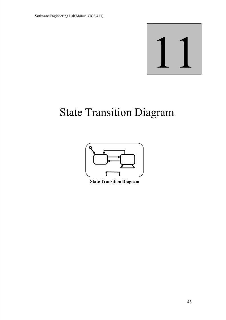
State Transition Diagram
11
State Transition Diagram
43
7/27/2019 6 SWE311 Revised Lab Manual Ultimate
http://slidepdf.com/reader/full/6-swe311-revised-lab-manual-ultimate 44/52
Software Engineering Lab Manual (ICS 413)
Lab 11: State Transition Diagrams
Objectives
• Deeper understanding of UML state transition diagrams (STD).
•
Practicing using Rational Rose.
1. Outline
• UML state diagrams.
• UML state diagram notation
• UML state details
• Examples
2. Background
Mainly, we use interaction diagrams to study and model the behavior of objects in our
system. Sometimes, we need to study the behavior of a specific object that shows
complex behavior to better understand its dynamics. For that sake, UML provides
state transition diagrams used to model the behavior of objects of complex behavior.
In this Lab, UML state transition diagrams will be introduced. We will study their
notation and how can we model them using Rational Rose.
2.1 UML State Diagrams
State diagrams show how one specific object changes state as it receives and
processes messages:
•
Since they are very specific, they are used for analyzing very specificsituations if we compare them with other diagrams.
• A state refers to the set of values that describe an object at a specific moment
in time.
• As messages are received, the operations associated with the object’s parent
class are invoked to deal with the messages.
• These messages change the values of these attributes.
• There is no need to prepare a state diagram for every class you have in the
system.
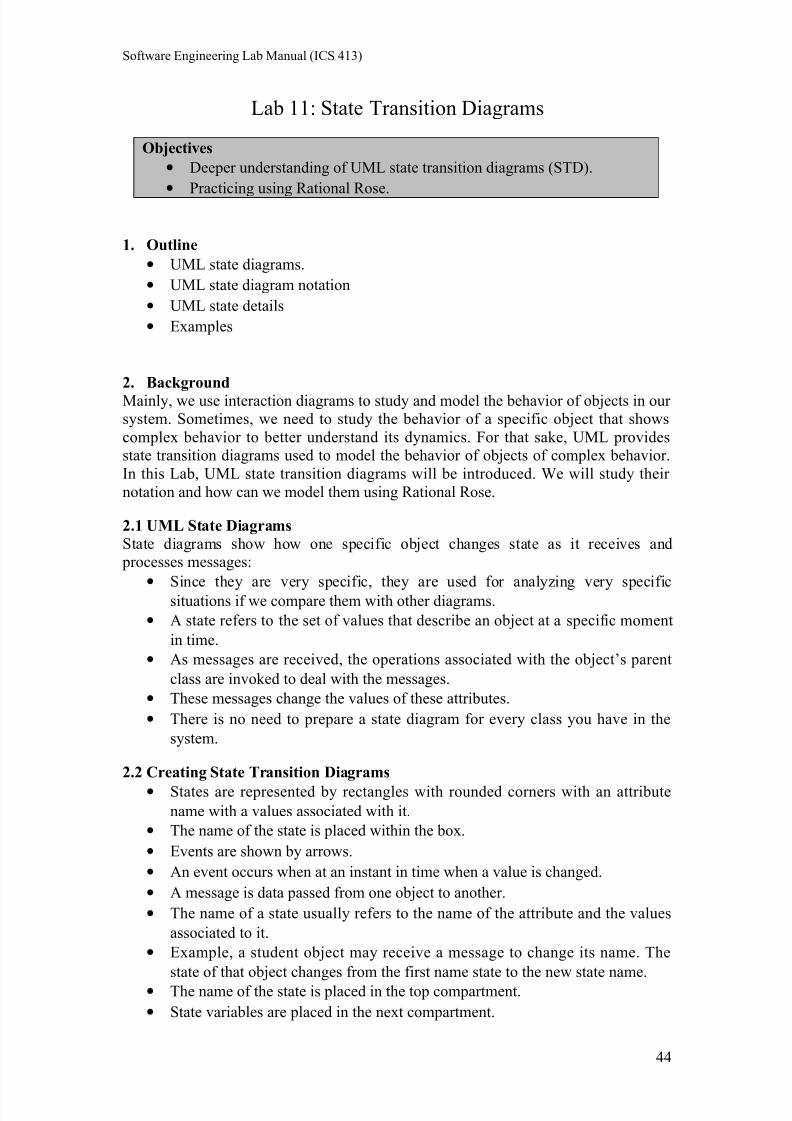
2.2 Creating State Transition Diagrams
• States are represented by rectangles with rounded corners with an attribute
name with a values associated with it.
• The name of the state is placed within the box.
• Events are shown by arrows.
• An event occurs when at an instant in time when a value is changed.
• A message is data passed from one object to another.
• The name of a state usually refers to the name of the attribute and the values
associated to it.
• Example, a student object may receive a message to change its name. The
state of that object changes from the first name state to the new state name.
• The name of the state is placed in the top compartment.
• State variables are placed in the next compartment.
44
7/27/2019 6 SWE311 Revised Lab Manual Ultimate
http://slidepdf.com/reader/full/6-swe311-revised-lab-manual-ultimate 45/52
Software Engineering Lab Manual (ICS 413)
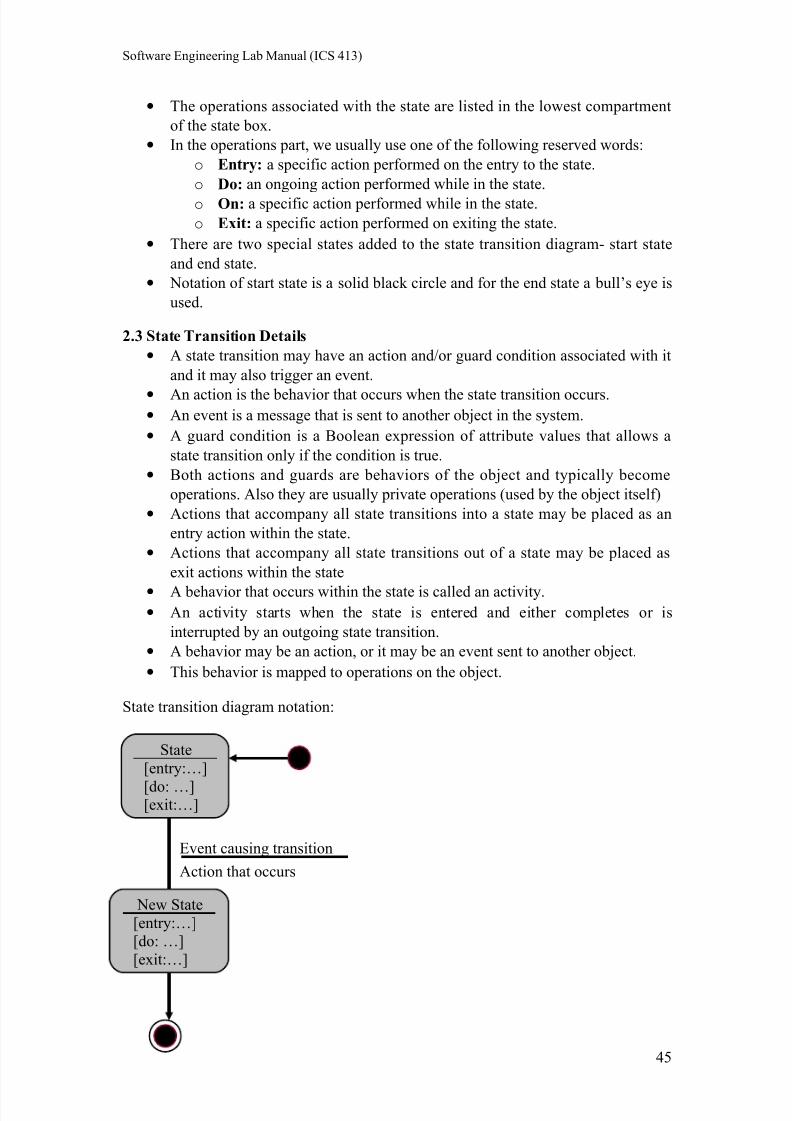
• The operations associated with the state are listed in the lowest compartment
of the state box.
• In the operations part, we usually use one of the following reserved words:
o Entry: a specific action performed on the entry to the state.
o Do: an ongoing action performed while in the state.
o On: a specific action performed while in the state.
o Exit: a specific action performed on exiting the state.
• There are two special states added to the state transition diagram- start state
and end state.
• Notation of start state is a solid black circle and for the end state a bull’s eye is
used.
2.3 State Transition Details
• A state transition may have an action and/or guard condition associated with it
and it may also trigger an event.
• An action is the behavior that occurs when the state transition occurs.• An event is a message that is sent to another object in the system.
• A guard condition is a Boolean expression of attribute values that allows a
state transition only if the condition is true.
• Both actions and guards are behaviors of the object and typically become
operations. Also they are usually private operations (used by the object itself)
• Actions that accompany all state transitions into a state may be placed as an
entry action within the state.
• Actions that accompany all state transitions out of a state may be placed as
exit actions within the state
• A behavior that occurs within the state is called an activity.• An activity starts when the state is entered and either completes or is
interrupted by an outgoing state transition.
• A behavior may be an action, or it may be an event sent to another object.
• This behavior is mapped to operations on the object.
State transition diagram notation:
Event causing transition
Action that occurs
New State
[entry:…]
[do: …]
[exit:…]
State
[entry:…]
[do: …][exit:…]
45
7/27/2019 6 SWE311 Revised Lab Manual Ultimate
http://slidepdf.com/reader/full/6-swe311-revised-lab-manual-ultimate 46/52
Software Engineering Lab Manual (ICS 413)
3. CASE Tools
Rational Rose (introduced in Lab 5).
4. In-Class Example
Now you will learn how to apply the above mentioned methods of drawing statetransition diagrams (STD). Please refer to Lab 11 slides which explain the process of
finding dynamic classes and creating STD with some examples.
5. Exercises
Here is what happens in a microwave oven:
1. The oven is initially in an idle state with door open, where the light is turned
on.
2. When the door is closed it is now in idle with door closed, but the light is
turned off.
3. If a button is pressed, then it moves to initial cooking stage, where the timer is set and lights are on, and heating starts
4. At any moment the door may be opened, the cooking is interrupted, the timer
is cleared, and heating stops.
5. Also while cooking, another button can be pushed and extended cooking
state starts, where the timer gets more minutes. At any moment door can be
opened here also.
6. If the time times out, then cooking is complete, heating stops, lights are off,
and it sounds a beep.
7. When the door is open, again the oven is in idle state with the door open.
Draw a state transition diagram for the microwave oven.
6. Deliverables
You should submit the solutions for the previous exercises.
You should use these techniques to create state transition diagrams for your term
project.
46
7/27/2019 6 SWE311 Revised Lab Manual Ultimate
http://slidepdf.com/reader/full/6-swe311-revised-lab-manual-ultimate 47/52
Software Engineering Lab Manual (ICS 413)
Implementation Diagrams:Component & Deployment Diagrams
12
47
7/27/2019 6 SWE311 Revised Lab Manual Ultimate
http://slidepdf.com/reader/full/6-swe311-revised-lab-manual-ultimate 48/52
Software Engineering Lab Manual (ICS 413)
Lab 12: Implementation Diagrams: Component & Deployment
Diagrams
Objectives
• Become familiar with the implementation diagrams: component anddeployment diagrams.
• Practice using Rational Rose.
1. Outline
• Implementation diagrams: component and deployment diagrams.
• Examples.
2. Background
Implementation diagrams capture design information. The main implementationdiagrams in UML are: component and deployment diagrams. In this Lab we will
study these diagrams and their notation.
2.1 UML Implementation Diagrams
The main implementation diagrams we have in UML are: component diagrams and
deployment diagrams. These diagrams are high level diagrams in comparison with old
diagrams you have already learned.
2.2 UML Component Diagram
Component diagrams capture the physical structure of the implementation.
• Remember always that when you talk about components, you are talking aboutthe physical models of code.
• You can name them and show dependency between different components
using arrows.
• A component diagram shows relationships between component packages and
components.
• Each component diagram provides a physical view of the current model.
• Component diagrams contain icons representing:
o Component packages.
o Components.
o Main programs.o Packages.
o Subprograms.
o Tasks.
o Dependencies.
2.3 Deployment Diagrams
A deployment diagram shows processors, devices and connections. Each model
contains a single deployment diagram which shows the connections between its
processors and devices, and the allocation of its processes to processors.
48
7/27/2019 6 SWE311 Revised Lab Manual Ultimate
http://slidepdf.com/reader/full/6-swe311-revised-lab-manual-ultimate 49/52
Software Engineering Lab Manual (ICS 413)
2.4.1 Deployment Diagrams: Processor
A processor is a hardware component capable of executing programs.
• A processor is given a name and you should specify the processes that will run
on that processor.
• You can also specify the scheduling of these processes on that processor.
• Types of scheduling are:
o Pre-emptive: a higher priority process may take the process from lower
priority one.
o Non-preemptive: a process will own the processor until it finishes
o Cyclic: control passes from one process to another.
o Executive: an algorithm controls the scheduling of the processes
o Manual: scheduling buy the user.
2.4.2 Deployment Diagrams: Device
A device is a hardware component with no computing power. Each device must have
a name. Device names can be generic, such as “modem” or “terminal.”
2.4.3 Deployment diagrams: Connection
A connection represents some type of hardware coupling between two entities. An
entity is either a processor or a device. The hardware coupling can be direct, such as
an RS232 cable, or indirect, such as satellite-to-ground communication. Connections
are usually bi-directional.
3. CASE Tools
Rational Rose (introduced in Lab 5).
4. In-Class Example
Now you will learn how to apply the above mentioned methods of creating
component and deployment diagrams. Please refer to Lab 12 slides which explain the
process of creating implementation diagrams with some examples.
5. Exercises
Think about any system and its components and draw deployment and component
diagrams.
6. Deliverables
You should submit the solutions for the previous exercises.
You should use these techniques to create component and deployment diagrams for
your term project.
49
7/27/2019 6 SWE311 Revised Lab Manual Ultimate
http://slidepdf.com/reader/full/6-swe311-revised-lab-manual-ultimate 50/52
Software Engineering Lab Manual (ICS 413)
Software Testing
13
50
7/27/2019 6 SWE311 Revised Lab Manual Ultimate
http://slidepdf.com/reader/full/6-swe311-revised-lab-manual-ultimate 51/52
Software Engineering Lab Manual (ICS 413)
Lab 13: Software Testing
Objectives
• Gain a deeper understanding of software testing and the software testing
document.• Become familiar with a software testing tool (JUnit).
1. Outline
• Overview of software testing.
• Unit testing.
• JUnit tutorial.
• Software test specification.
2. Background
Testing is the process of executing a program with the intent of finding errors. A good
test case is one with a high probability of finding an as-yet undiscovered error. A
successful test is one that discovers an as-yet-undiscovered error.
The causes of the software defects are: specification may be wrong; specification may
be a physical impossibility; faulty program design; or the program may be incorrect.
2.1 Basic Definitions
• A failure is an unacceptable behavior exhibited by a system.
• A defect is a flaw in any aspect of the system that contributes, or may
potentially contribute, to the occurrence of one or more failures. It might takeseveral defects to cause a particular failure.
• An error is a slip-up or inappropriate decision by a software developer that
leads to the introduction of a defect.
2.2 Good Test Attributes
A good test has a high probability of finding an error, not redundant, and should not
be too simple or too complex.
2.3 Unit Testing
Unit testing is testing each unit separately. In unit testing interfaces tested for proper information flow and local data are examined to ensure that integrity is maintained.
Boundary conditions and all error handling paths should also be tested.
3. CASE Tools
JUnit is an open-source project to provide a better solution for unit testing in Java. It
can be integrated with many Java IDEs.
Central idea: create a separate Java testing class for each class you’re creating, and
then provide a means to easily integrate the testing class with the tested class for unit
testing.
51
7/27/2019 6 SWE311 Revised Lab Manual Ultimate
http://slidepdf.com/reader/full/6-swe311-revised-lab-manual-ultimate 52/52
Software Engineering Lab Manual (ICS 413)
3.1 JUnit Terminology
• A unit test: is a test of a single class.
• A test case: tests the response of a single method to a particular set of inputs.
• A test suite: is a collection of test cases.
• A test runner: is software that runs tests and reports results.
• A test fixture: sets up the data (both objects and primitives) that are needed to
run tests. For example if you are testing code that updates an employee record,
you need an employee record to test it on.
3.2 How JUnit Works
• Define a subclass of TestCase.
• Override the setUp() & tearDown() methods.
• Define one or more public testXXX()methods
o Exercise the object(s) under test.
o Asserts the expected results.
• Define a static suite() factory method
o Create a TestSuite containing all the tests.
• Optionally define main() to run the TestCase in batch mode.
4. In-Class Demo
A tutorial on how to use JUnit with some example will be presented. Please refer to
Lab 13 slides for an overview of software testing and JUnit tutorial with some
examples.
5. Exercises
Write a JUnit test class for testingpublic class Exercise {
/** Return the minimum of x and y. */
public static int min(int x, int y) { ... }
}
6. Deliverables
• You should submit the solutions for the previous exercise.
•Also, if you are building your project using Java, you should use JUnit for testing.


![Ultimate Frisbee Unit[1] Revised](https://img.pdfslide.net/doc/110x75/55cf93be550346f57b9e3ef2/ultimate-frisbee-unit1-revised.jpg)