Embed Size (px)
Citation preview
6 1 0 LCÛC NORTH AMERICA VOLUME 26 NUMBER? JULY ZOOB www.chromaXographyonlinexom
What causes split or
fronting peaks?
LC TROUBLESHOOTING
Peak Shape Problems
John W. DolanLC Troubleshooting Editor
M ost of us are quite familiarwith tailing peaks in liquidchromatography (LC) sepa-
rations. In my experience, it is a rarechromatogram that is free of peak tail-ing. Peak tailing is understood reason-ably well by mosc workers. In reversed-phase separations, it is due primarily tounwanted secondary interactions —•especially basic and acidic compoundsthat undergo ion exchange or interac-tion with metal contaminants in the sil-ica-based stationary phase. These tailingproblems usually affect just one or a fewpeaks in a chromatogram. What aboutthose chromatograms in which all thepeaks have severely tailing peaks, or splitor doubled peaks? Then there are peaks[hat front badly —• a rare event for mostworkers — but common under certainconditions. This months "LC Trou-bleshooting" column will consider theselast two problem areas.
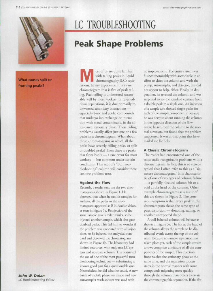
Against the FlowRecently, a reader sent me the two chro-matograms shown in Figure 1. Heobserved that when he ran his samples foranalysis, all the peaks in the chro-macogram appeared as if in double vision,as seen in Figure la. Reinjection of thesame sample gave similar results, so heinjected another sample, which also gavedoubled peaks. This led him to wonder ifthe problem was associated with all injec-tions, so he injected die analytical stan-dard and observed the chromatogramshown in Figure Ib. The laboratory hadlimited resources, with only one LC sys-tem and no spare column. This restrictedthe use of one of the most powerhil trou-bleshooting techniques — substituting aknown good part for a questionable one.Nevertheless, he did what he could. A newbatch of mobile phase was made and newautosampler wash solvent was used with
no improvement. The entire system wasHushed thoroughly with acetonitrile in aneffort to clean the column and wash thepump, autosampler, and deteaor; this didnot appear to help, either. Finally, in des-peration, he reversed the column, and wassurprised to see the standard coalesce fi'oma double peak to a single one. An injectionof a sample also showed single peaks foreach of the sample components. Becausehe was nervous about running the columnin die opposite direction of the flowarrow, he returned the column to the nor-mal direction, but found that the problemreappeared. It was at that point that he e-mailed me for help.
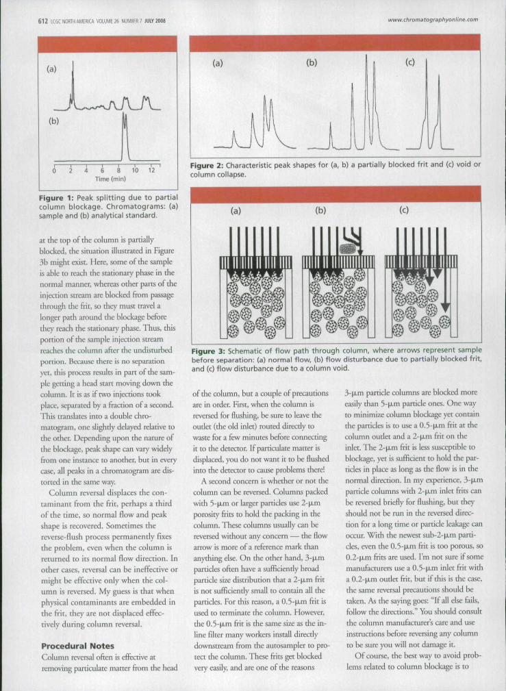
A Classic ChromatogramThe reader had encountered one of themost easily recognizable problems with achromatogram. In fact, this is so stereo-typical that I often refer to this as a "sig-nature chromatogram." It is characteris-tic of one of two types of column failure— a partially blocked column frit or avoid at the head of the column. Otherexample chromatograms as a result ofthis are shown in Figure 2. The com-mon symptom is that every peak in thechromatogram shows the same type ofpeak distortion — doubling, tailing, oranother unexpected shape.
A well-behaved column will behave asshown in Figure 3a. The frit at the head ofthe column allows the sample to be dis-tributed evenly across the top of the col-umn. Because no sample separation has[aken place yet, each of the sample-screamarrows comprises a mixture ot all tbe com-ponents of the sample. This injectionfront reaches the stationary phase at thesame time, and the separation processstarts in the normal manner with somecompounds migrating more quicklythrough the column than others to createthe Chromatographie separation, If the frit
6 1 2 LCGC NORTH AMERICA VOLUME 26 NUMBER 7 JUIY Î008 www. chromatographyQnllne.com
10 12Time (min)
Figure 1: Peak splitting due to partialcolumn blockage. Chromatograms: (a)sample and (b) analytical standard.
at the top of the column is partiallyblocked, the situation illustrated in Figure3b migbt exist. Here, some of the sampleis able to reach the stationary phase in thenormal manner, whereas other parts of theinjection stream are blocked from passagetlirough die frit, so they must travel alonger path around the blockage beforethey reach the stationary phase. Thus, thisportion of the sample injection streamreaches the coltunn after the undisturbedportion. Because there ¡s no separationyet, this process results in part of the sam-ple getting a head start moving down thecolumn. It is as if two injections tookplace, separated by a fraction of a second.This translates into a double chro-matogram, one slightly delayed relative tothe other Depending upon the nature ofthe blockage, peak shape can vary widelyfrom one instance to another, but in everycase, all peaks in a chromatogram are dis-torted in the same way.
Column reversal displaces the con-taminant from the frit, perhaps a thirdof the time, so normal flow and peakshape Is recovered. Sometimes thereverse-flush process permanently fixesthe problem, even when the column isreturned to Its normal flow direction. Inother cases, reversal can be ineffective ormight be effective only when the col-umn is reversed. My guess ¡s that whenphysical contaminants are embedded inthe frit, they are not displaced effec-tively during column reversal.
Procedural NotesColumn reversal often is cfFeaive atremoving partíctilate matter from the head
(a) ib) (0
Figure 2: Characteristic peak shapes for (a, b) a partially blocked frit and (c) void orcolumn collapse.
(a) (b) (c)
Figure 3: Schematic of flow path through column, where arrows represent samplebefore separation: (a) normal flow, (b) flow disturbance due to partially blocked frit,and (c) flow disturbance due to a column void.
of the column, but a couple of precautionsare in order. First, when the cwlumn isreversed for flushing, be stire to leave theoutlet (the old inlet) routed direcdy towaste for a few minutes before connectingit to the detector. If partictxiate matter isdisplaced, you do not want it to be flushedinto the detector to cause problems there!
A second concern is whether or not thecolumn can be reversed. Columns packedwith 5-|xm or larger particles use 2-p,mporosity frits to hold the packing In thecolumn. These columns usually can bereversed without any concern — the flowarrow is more of a reference mark thananything else. On the other hand, 3'fJLmparticles often have a sufFiciendy broadparticle size distribution that a 2-p,m fritis not sufficiently small to contain all theparticles. For this reason, a 0.5-p.m frit isused to terminate the coltimn. However,the 0.5-ixm frit is the same size as the in-line filter many workers install directlydownstream from the aurosampler to pro-tect the coltunn. These frits get blockedvery easily, and are one of the reasons
3-|xm particle columns are blocked moreeasily than 5-fJLm particle ones. One wayto minimize column blockage yet containthe particles is to use a 0.5-|JLm frit at thecolumn outlet and a l-\Lm frit on theinlet. The 2-̂ JLm frit is less susceptible toblockage, yet is sufficient to hold the par-ticles in place as long as the flow is in thenormal direction. In my experience, 3-iJLniparticle columns with 2-|xm inlet frits canbe reversed briefly for flushing, but theyshotild not be run in the reversed direc-tion for a long time or particle leakage canoccur. With the newest sub-2-ixm parti-cles, even the 0.5-M-m frit is too porous, so0.2-p.m frits are used. I'm not sure if somemanufacturers use a 0.5-(xm inlet frit witha 0.2-p..m outlet frit, but if this is the case,the same reversal precautions should betaken. As the saying goes: "If all else fails,follow the direaions." You shotild consultthe column manufacturer's care and useinstructions before reversing any columnto be sure you will not damage It.
Of course, the best way to avoid prob-lems related to column blockage is to
6 1 4 LCGCTORIH AMERICA VOLUME 26 NUMBER? JULY 2008 www.ctiromatographyonline.com
minimize the exposure of the column topaniculate matter. This means that thesample preparation process shouldinclude a step to remove particles. Someworkers like to filter all the samples, butthis is expensive and might require extravalidation steps to ensure that sample isnot selectively lost on the filter or thatcontaminants are added by the filter. Mypreference is to centrifuge all samplesbriefly in a benchtop centrifuge beforeplacing them in the autosampler vials.
Fronting PeaksWhereas tailing peaks are fiiirly ubiqui-
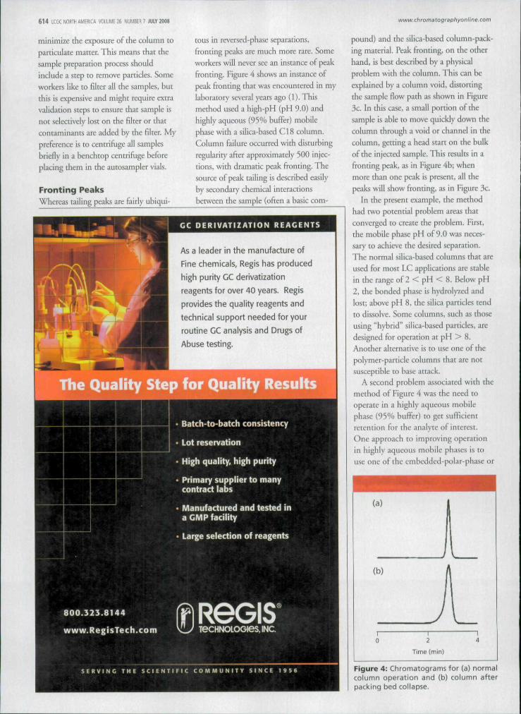
tous in reversed-phase separations,fronting peaks are much more rare. Someworkers will never see an instance of peakfronting. Figure 4 shows an instance ofpeak fronting that was encountered in mylaboratory several years ago (1). Thismethod used a high-pH (pH 9.0) andhighly aqueous {95% buffer) mobilephase with a silica-based C18 column.Column failure occurred with disturbingregLilarity after approximately 500 injec-tions, with dramatic peak fronting. Thesource of peak tailing is described easilyby secondary chemical interactionsbetween the sample (often a basic com-
800.323.8144
www.RegÍ5Tech.com
CC DERIVATIZATION REAGENTS
As a leader in the manufacture of
Fine chemicals, Regis has produced
high purity CC derivatization
reagents for over 40 years. Regis
provides the quality reagents and
technical support needed for your
routine GC analysis and Drugs of
Abuse testing.
Batch-to-batcn consistency
Lot reservation
High quality, high purity
Primary supplier to manycontract labs
Manufactured and tested ina GMP facility
Large selection of reagents
ReGISTeCHNOLOGieSJNC
S E R V I N G T H E S C I i N T I F I C C O M M U N I T Y S I N C E 1 9 5 6
pound) and the silica-based column-pack-ing material. Peak fronting, on the otherhand, is best described by a physicalproblem with the column. This can beexplained by a column void, distortingthe sample flow path as shown in Figure3c. In this case, a small portion of thesample is ahle to move quickly down thecolumn through a void or channel in thecolumn, getting a head start on the bulkof the injected sample. This results in afronting peak, as in Figure 4b; whenmore than one peak is present, all thepeaks will show fronting, as in Figure 3c.
In the present example, the methodhad two potential problem areas thatconverged to create the problem. First,[he mobile phase pH of 9.0 was neces-sary to achieve the desired separation.The normal silica-based columns that areused for most LC applications are stablein the range of 2 < pH < 8. Below pH2, the bonded phase is hydrolyzed andlost; above pH 8, the silica particles tendto dissolve. Some columns, such as thoseusing "hybrid" silica-based particles, aredesigned for operation at pH > 8.Another alternative is to use one of thepolymer-particle columns that are notsusceptible to base attack.
A second problem associated with themethod of Figure 4 was the need tooperate in a highly aqueous mobilephase (95% buffer) to get sufficientretention for the analyte of interest.One approach to improving operationin highly aqLicous mobile phases Is touse one of the embedded-polar-phase or
(a) i
1(b) /
[
1 1 i
0 2 4
Time (min)
Figure 4: Chromatograms for (a) normalcolumn operation and (b) column afterpacking bed collapse.

6 1 6 LCGC NORTH AMERO VOLUME 26 NUMBER 7 JULÏ 2008 www, chromatographyonline.com
"AQ"-type columns that many manu-facturers sell for use with 100% aqueousmobile phases. Another option for useof highly aqueous mobile phases that atleast one manufacturer uses is to reducethe surface coverage of the CI8 phase sothat more of the polar silica surface isexposed. This was the type of columnused for the separation of Figure 4.
Unfortunately, two influences con-verged to make this column and mobilephase combination a problem — high-pH mobile phase plus a low-coveragecolumn. The column collapsed afterapproximately 500 injections, as indi-cated by a badly fronting peak (Figure4b). Fortunately, the peak area was nocaffected for our method, so failure duringa sample batch allowed for accuratequantification of the samples, even withfronting peaks. The column, of course,was replaced before another sample batchwas run. One can only speculate on howthis deadly combination was missed dur-ing development and validation of themethod, but by the time it was realized,correction of the problem would haverequired revaJidation of the method. Wefound that the data were sufficiently
accurate for the application and themethod has performed well for morethan 10,000 samples. Yes, columnreplacement is expensive, but the columncost is only a small fraction of the overallanalysis cost. A typical LC-tandem massspectrometry (MS-MS) method such asthis costs $50-$100/sample. so a $500column replaced after 500 injectionsamounts to < 2% of the overall costs —certainly not worth the expense of revali-dating the method in the present case.
ConclusionsPhysical problems at the inlet of the col-umn can cause split or doubled peaks orpeak fronting. These problems oftenrequire replacement of the column. Ifthecolumn life and the data quality are suffi-cient, it mighc not be worth changing themethod to avoid problems. Two simplepraaices should minimize or eliminate theproblems discussed this month. The useof a 0.5-M.m porosity in-line filter plussample centrifligation or filtration shouldprevent problems associated with columnblockage. Careful adherence to the recom-mended mobile-phase pH limits or selec-don of a column designed for high-pH
work should have avoided the problemsassociated with fronting peaks.
References(1) R.D. Morrison and J.W. Dolan, LCGC 23,
566-574 (2005).
For more information on this topic,please visit
www.chromato9raphyonline.com/dolan
John W. Dolan"LC Troubleshoot-ing" Editor JohnW. Dolan is Vice-president of LCResources, WalnutCreek, California;and a member ofLCGC's editorialadvisory board.Direct correspondence about this column to"LC Troubleshooting," LCGC, WoodbridgeCorporate Plaza, 485 Route 1 South, Build-ing F, First Floor, Isetin, NJ 08830, e-mailJohn.Dolan^LCResources.com.
For an ongoing discussion of LC trouble-shooting with John Dolan and other chro-matographers, visit the ChromatographyForum discussion group at httpUiwww.chromforum.com.
Laboratory & Process Instrumentation Services
Calibration • Repair Services • Metrology Asset Management
Baseline Service has been providing multi-vendor Laboratory Instrumentation Services for over 14 years.Our success is based on providing "quality service" with a personal touch to our growing list of satisfied customers.
Process Instrumentation
• Temperature
Q Pressure
• Ph/Conductivity
n Pipettes
• Humidity
• Chart Recorders
Q Balances
• Physical DimensionalAnd More
Analytical Instrumentation
G LC
n GC
n Spectrophotometers
• Centrifuge
• Mass Specn Laboratory Weights
• DissolutionAnd More
Contact us for an evaluation of your requirement.
j | www.BaseîineService.com (732)-563-1200


![C omparison of the acidity of residual silanol groups in ...quimica.udea.edu.co/~carlopez/cromatohplc/comparis_2003_hplc.pdf · M C i51 n k 5KB2]A(S) (13) It must be noted that the](https://img.pdfslide.net/doc/110x75/5eba43f79fc1683ba43ccd73/c-omparison-of-the-acidity-of-residual-silanol-groups-in-carlopezcromatohplccomparis2003hplcpdf.jpg)


![Review Overview of the applications of liquid ...quimica.udea.edu.co/~carlopez/cromatohplc/review_hplc_ms_foods.pdfgiving positive identification of components of ... [29–31] mass](https://img.pdfslide.net/doc/110x75/5adb8ac87f8b9aee348e2d80/review-overview-of-the-applications-of-liquid-carlopezcromatohplcreviewhplcmsfoodspdfgiving.jpg)