Embed Size (px)
Citation preview
6/10/2003 – e.heine VLVnT facility-power 1EFNI HK
IntroductionIntroduction
• Hypothesis• Topology, technical constrains• Redundancy, budget constrains• Grounding• Reliability• Conclusion
EFNI HKE. Heine, H.Z. Peek
6/10/2003 – e.heine VLVnT facility-power 2EFNI HK
HypothesisHypothesis
• PowerVLVnT structure = 10 * Antares VLVnT power < 5 * Antares = 100 kW
Technology progress
Structure upgrades
Demands of other users?
• EnvironmentalDistance shore-facility = 100 kmPower cables combined with fibersSingle point failures has to avoid
6/10/2003 – e.heine VLVnT facility-power 3EFNI HK
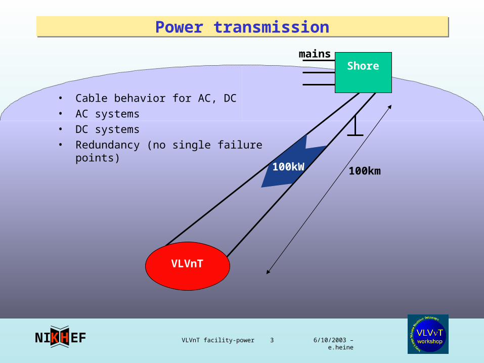
Power transmissionPower transmission
• Cable behavior for AC, DC• AC systems• DC systems• Redundancy (no single failure points)
Shore
VLVnT
100km
mains
100kW
6/10/2003 – e.heine VLVnT facility-power 4EFNI HK
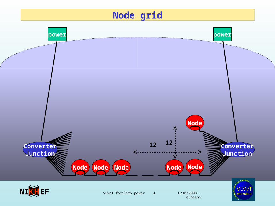
Node gridNode grid
Node Node Node Node Node
Node
12ConverterJunction
ConverterJunction
powerpower
12
6/10/2003 – e.heine VLVnT facility-power 5EFNI HK
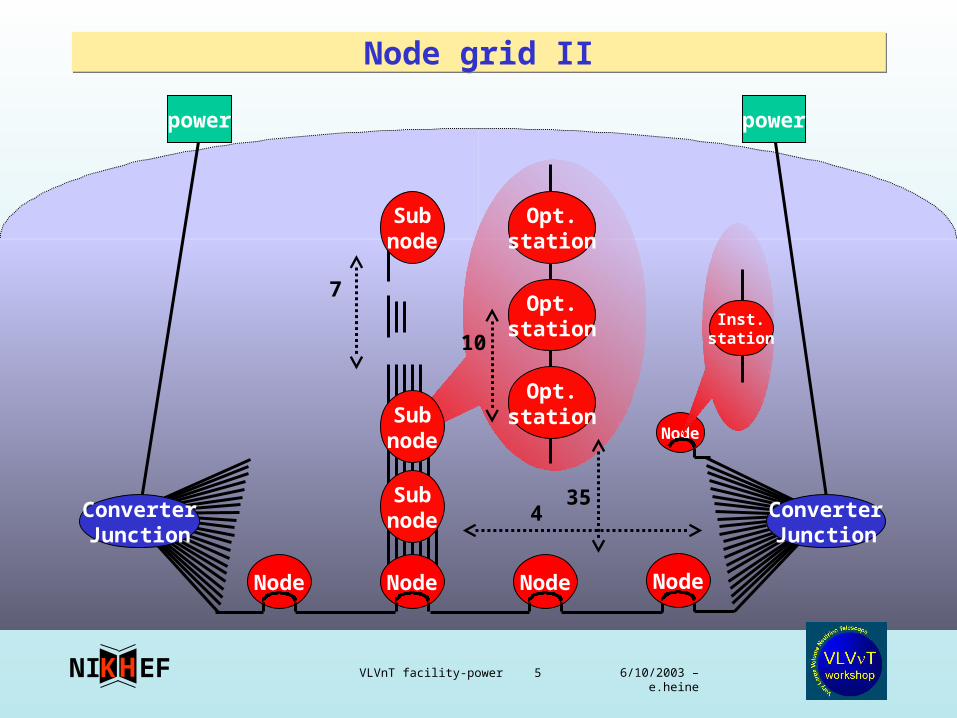
Node grid IINode grid II
Node
435
Node Node Node Node
ConverterJunction
ConverterJunction
powerpower
Subnode
Subnode
7
Opt.station
Opt.station
Opt.station
10
Subnode
Inst.station
6/10/2003 – e.heine VLVnT facility-power 6EFNI HK
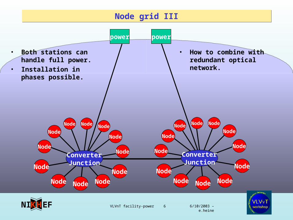
Node grid IIINode grid III
power power
Node
ConverterJunction
Node
Node
Node
Node
Node
Node
Node
Node Node
NodeNodeNode
ConverterJunction
Node
Node
Node
Node
Node
Node
Node
NodeNode
Node Node
• Both stations can handle full power.
• Installation in phases possible.
• How to combine with redundant optical network.
6/10/2003 – e.heine VLVnT facility-power 7EFNI HK
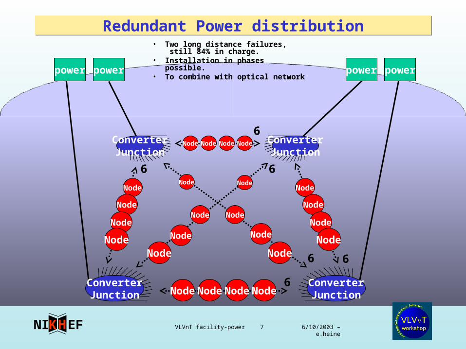
Redundant Power distributionRedundant Power distribution
Node
Node
Node
Node
NodeNodeNodeNode
NodeNodeNodeNode
Node
Node
Node
NodeNodeNode
NodeNode
NodeNode
NodeNode
66
6
6
6
6
power
ConverterJunction
ConverterJunction
power power power
ConverterJunction
ConverterJunction
• Two long distance failures, still 84% in charge.
• Installation in phases possible.• To combine with optical network
6/10/2003 – e.heine VLVnT facility-power 8EFNI HK
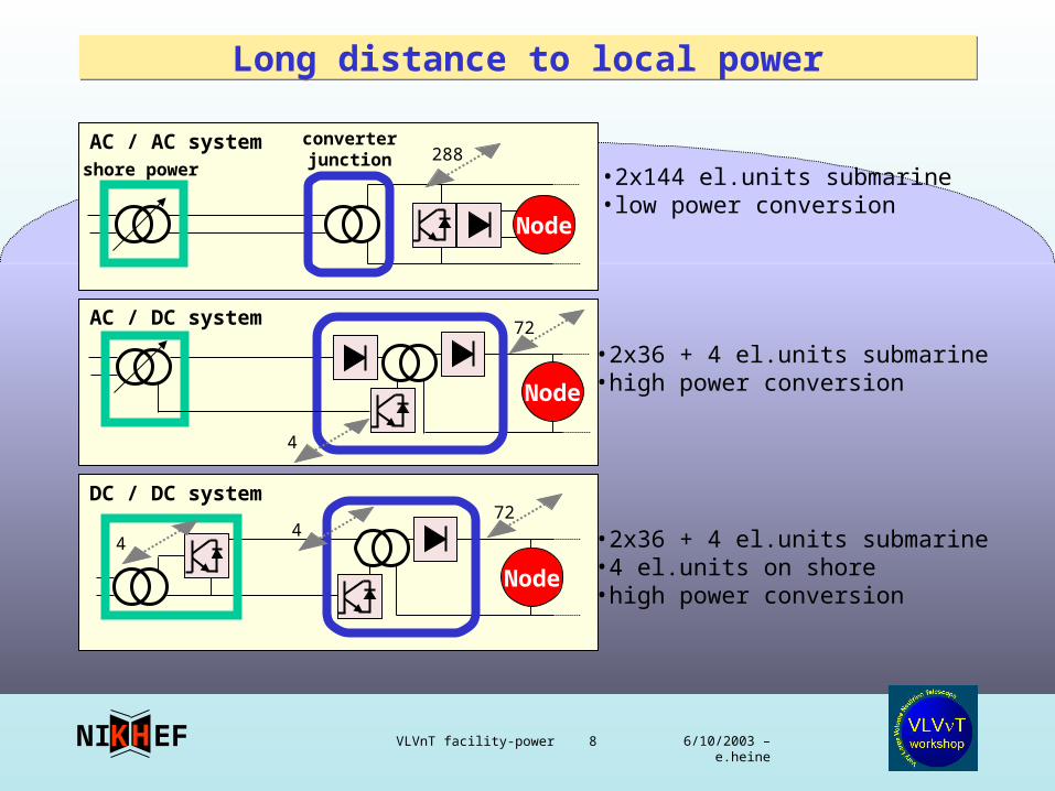
Long distance to local powerLong distance to local power
AC / DC system
Node
DC / DC system
Node
AC / AC system converterjunction
shore power
Node
•2x144 el.units submarine•low power conversion
•2x36 + 4 el.units submarine•high power conversion
•2x36 + 4 el.units submarine•4 el.units on shore•high power conversion
288
72
4
724
4
6/10/2003 – e.heine VLVnT facility-power 9EFNI HK
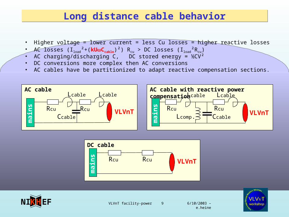
Long distance cable behaviorLong distance cable behavior
• Higher voltage = lower current = less Cu losses = higher reactive losses• AC losses (Iload²+(kUCcable)²) Rcu > DC losses (Iload²Rcu)• AC charging/discharging C, DC stored energy = ½CV²• DC conversions more complex then AC conversions• AC cables have be partitionized to adapt reactive compensation sections.
AC cable
DC cable
AC cable with reactive power compensation
VLVnT VLVnT
VLVnT
mai
ns
Rcu Rcu Rcu Rcu
Rcu Rcu
Ccable
Lcable
Lcomp. Ccable
Lcable Lcable Lcable
mai
ns
mai
ns
6/10/2003 – e.heine VLVnT facility-power 10EFNI HK
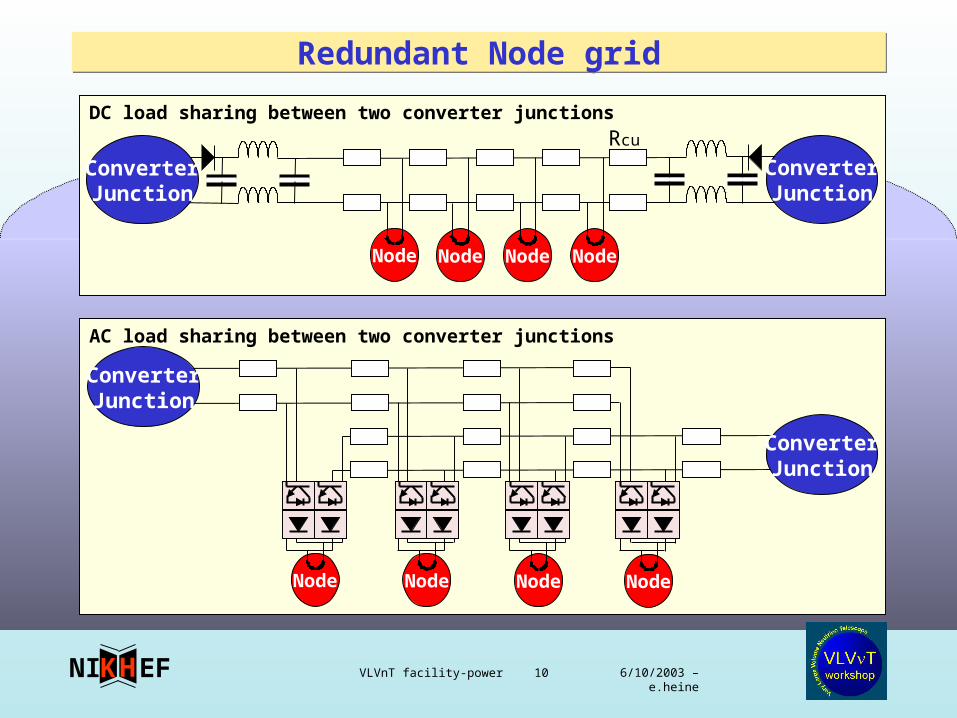
Redundant Node gridRedundant Node grid
DC load sharing between two converter junctions
Rcu
AC load sharing between two converter junctions
ConverterJunction
ConverterJunction
Node Node Node Node
Node Node Node Node
ConverterJunction
ConverterJunction
6/10/2003 – e.heine VLVnT facility-power 11EFNI HK
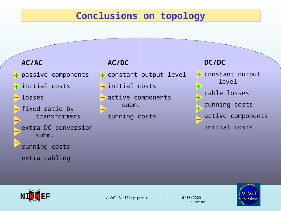
Conclusions on topologyConclusions on topology
AC/AC
passive components
initial costs
losses
fixed ratio by transformers
extra DC conversion subm.
running costs
extra cabling
AC/DC
constant output level
initial costs
active components subm.
running costs
DC/DC
constant output level
cable losses
running costs
active components
initial costs
++
+++
+
+
6/10/2003 – e.heine VLVnT facility-power 12EFNI HK
Node
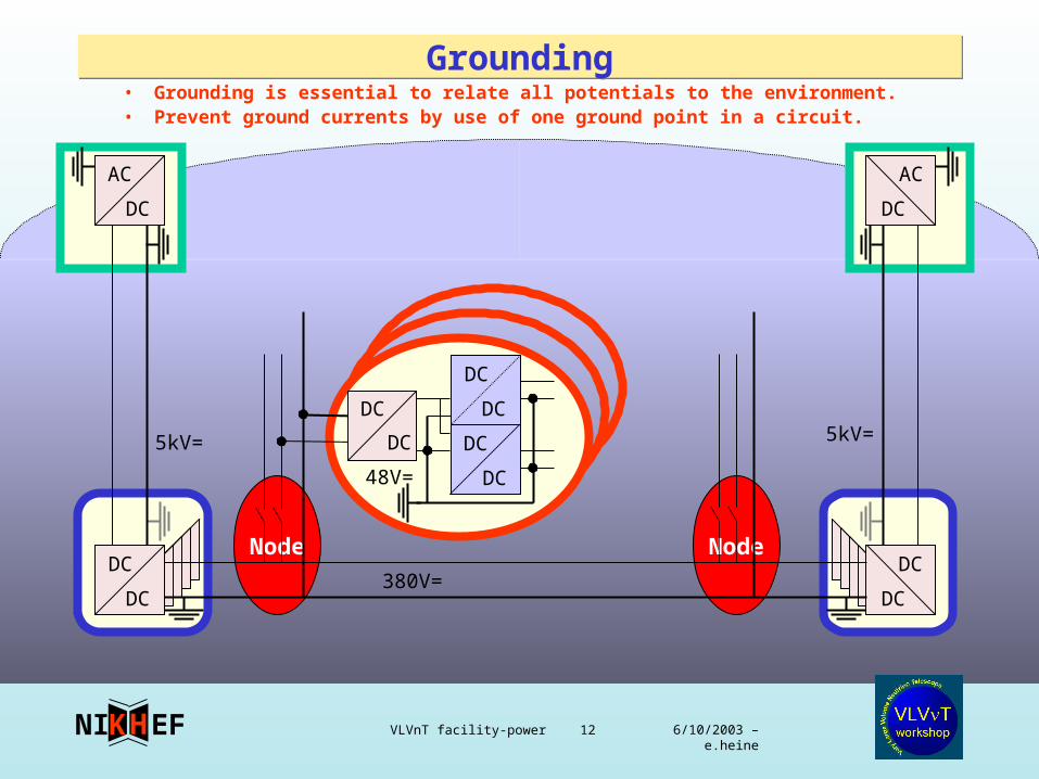
GroundingGrounding
Node
AC
DC
DC
DC
DC
DC
DC
DC
AC
DC
DC
DC
DC
DC
48V=
380V=
5kV= 5kV=
• Grounding is essential to relate all potentials to the environment.• Prevent ground currents by use of one ground point in a circuit.
6/10/2003 – e.heine VLVnT facility-power 13EFNI HK
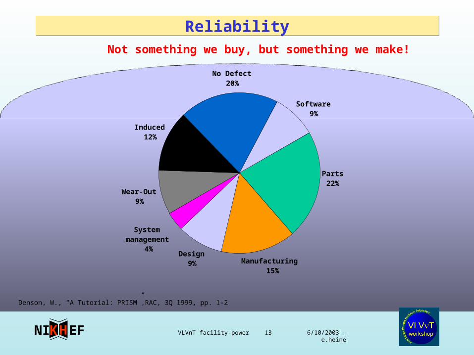
ReliabilityReliabilityNot something we buy, but something we make!
Denson, W., “A Tutorial: PRISM”,RAC, 3Q 1999, pp. 1-2
Parts22%
Manufacturing 15%
Design9%
Induced12%
No Defect20%
System management
4%
Wear-Out9%
Software9%
6/10/2003 – e.heine VLVnT facility-power 14EFNI HK
General conclusionsGeneral conclusions
• Technical issues to investigate– DC for long distance is promising-> breakeven study for costs and redundancy– node grid gives redundancy– node grid can be made of components used in railway industry– inter module grid can be made of components used in automotive industry– each board / module makes its own low voltages
• Organization– power committee recommend– specify the power budget (low as possible, no changes)– coordination of the grounding system before realizing– watching test reports, redundancy and reliability– try to involve a technical university for the feasibility study– coordination between power and communication infrastructures
6/10/2003 – e.heine VLVnT facility-power 15EFNI HK
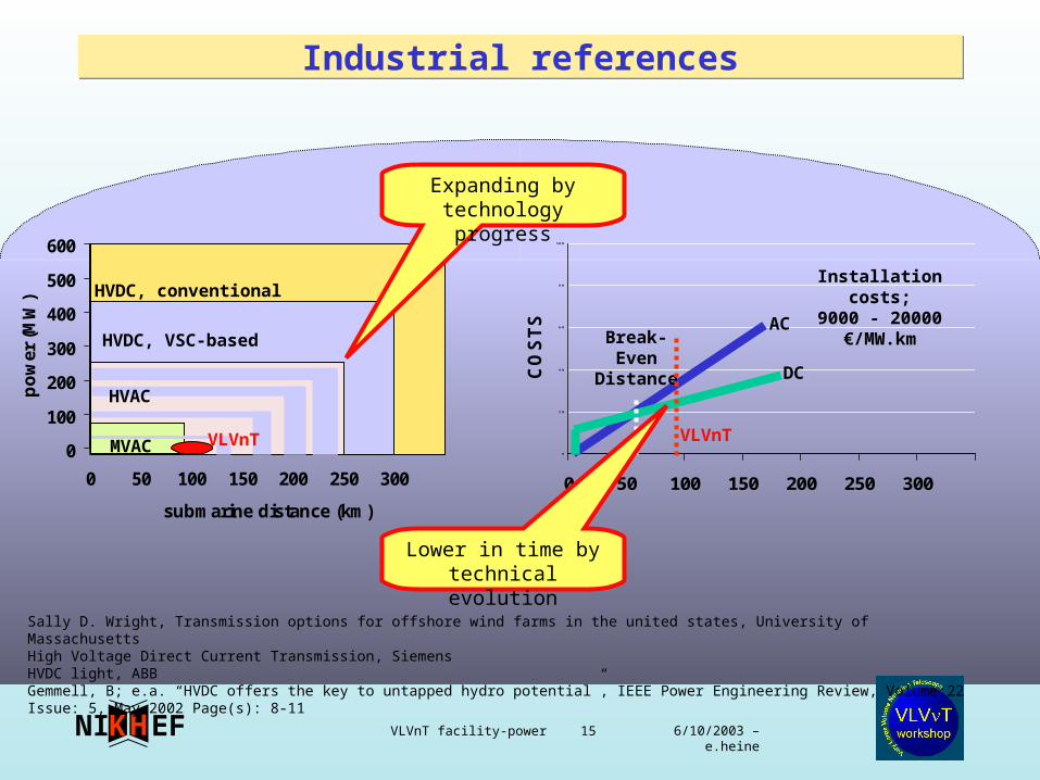
Industrial referencesIndustrial references
0
100
200
300
400
500
600
0 50 100 150 200 250 300
submarine distance (km)
po
wer
(M
W) HVDC, conventional
HVDC, VSC-based
HVAC
MVAC VLVnT
Sally D. Wright, Transmission options for offshore wind farms in the united states, University of MassachusettsHigh Voltage Direct Current Transmission, SiemensHVDC light, ABBGemmell, B; e.a. “HVDC offers the key to untapped hydro potential”, IEEE Power Engineering Review, Volume:22 Issue: 5, May 2002 Page(s): 8-11
0
2 0
4 0
6 0
8 0
10 0
0 50 100 150 200 250 300
CO
ST
S
VLVnT
Break-Even
Distance DC
AC
Installation costs;
9000 - 20000€/MW.km
Lower in time bytechnical evolution
Expanding by technology progress
6/10/2003 – e.heine VLVnT facility-power 16EFNI HK
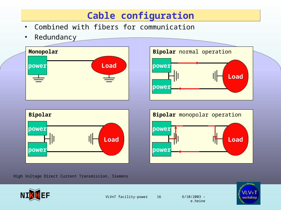
Monopolar
Cable configurationCable configuration• Combined with fibers for communication
• Redundancy
power Load
Bipolar
power
power
Load
Bipolar normal operation
power
power
Load
Bipolar monopolar operation
power
power
Load
High Voltage Direct Current Transmission, Siemens
6/10/2003 – e.heine VLVnT facility-power 17EFNI HK
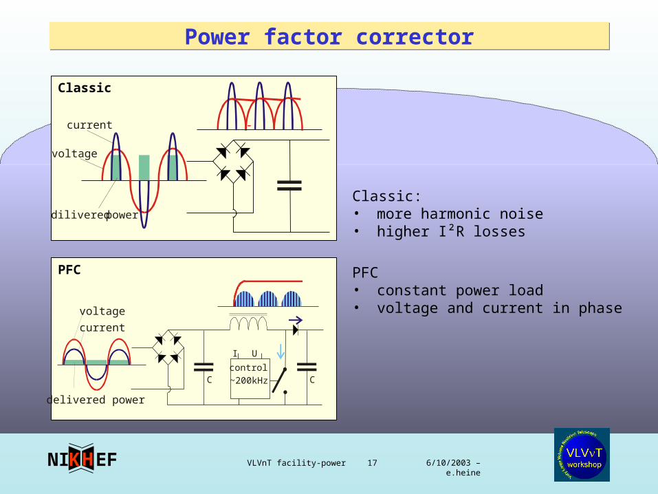
Power factor correctorPower factor corrector
Classic
PFC
dilivered power
current
voltage
delivered power
current
voltage
C Ccontrol
I U
~200kHz
Classic: • more harmonic noise• higher I²R losses
PFC• constant power load• voltage and current in phase
6/10/2003 – e.heine VLVnT facility-power 18EFNI HK
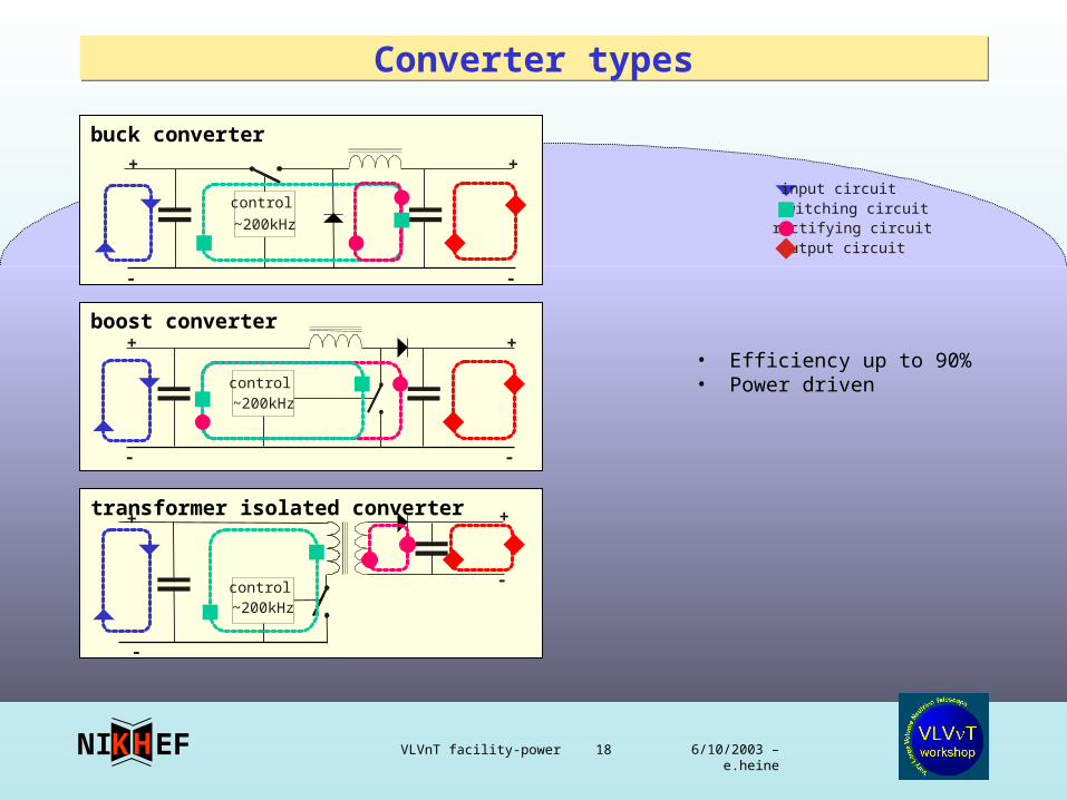
Converter typesConverter types
buck converter
boost converter
transformer isolated converter
control
~200kHz
input circuitswitching circuitrectifying circuitoutput circuit
control~200kHz
control~200kHz
+
-
+
-
+
-
+
-
+
-
+
-
• Efficiency up to 90%• Power driven
6/10/2003 – e.heine VLVnT facility-power 19EFNI HK
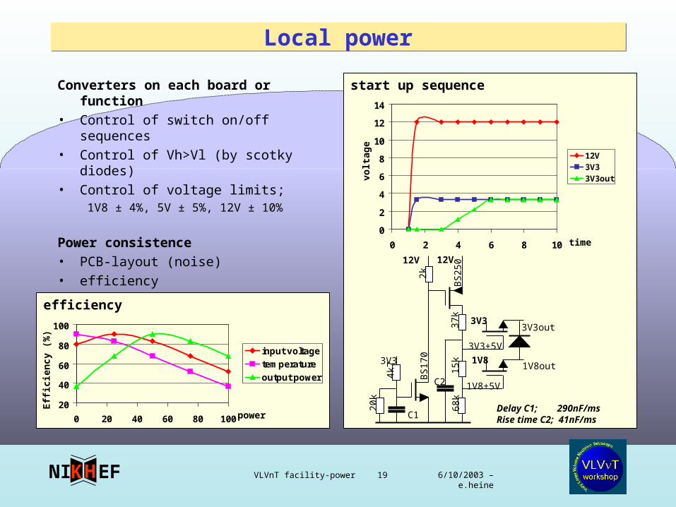
start up sequence
Local powerLocal power
Converters on each board or function • Control of switch on/off sequences• Control of Vh>Vl (by scotky diodes)• Control of voltage limits;
1V8 ± 4%, 5V ± 5%, 12V ± 10%
Power consistence• PCB-layout (noise)• efficiency
0
2
4
6
8
10
12
14
0 2 4 6 8 10
12V3V33V3out
12V12V
3V3
3V33V3out
1V8out1V8
3V3+5V
1V8+5V
C1
C2
Delay C1; 290nF/msRise time C2; 41nF/ms
68k
15k
37k
BS
250
BS
170
20k
4k7
2k
efficiency
20
40
60
80
100
0 20 40 60 80 100
input voltage
temperature
output power
time
power
Eff
icie
ncy
(%
)
volt
age