Embed Size (px)
Citation preview
INSTALLATION INSTRUCTIONS
62-0306-04
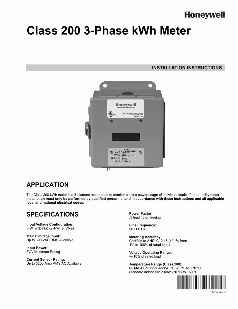
Class 200 3-Phase kWh Meter
APPLICATION
The Class 200 kWh meter is a 3-element meter used to monitor electric power usage of individual loads after the utility meter. Installation must only be performed by qualified personnel and in accordance with these instructions and all applicable local and national electrical codes.
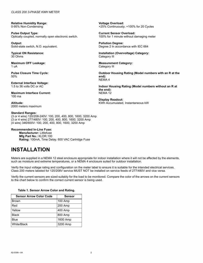
SPECIFICATIONS
Input Voltage Configuration:3-Wire (Delta) or 4-Wire (Wye)
Mains Voltage Input:Up to 600 VAC RMS Available
Input Power:6VA Maximum Rating
Current Sensor Rating:Up to 3200 Amp RMS AC Available
Power Factor:.5 leading or lagging
Line Frequency:50 - 60 Hz.
Metering Accuracy:Certified to ANSI C12.16 (+/-1% from1% to 100% of rated load)
Voltage Operating Range:+/-10% of rated load
Temperature Range (Class 200):NEMA 4X outdoor enclosure: -20 ºC to +70 ºCStandard indoor enclosure: -20 ºC to +50 ºC
CLASS 200 3-PHASE KWH METER
62-0306—04 2
Relative Humidity Range:0-95% Non-Condensing
Pulse Output Type:Optically coupled, normally open electronic switch.
Output:Solid-state switch, N.O. equivalent.
Typical ON Resistance:30 Ohms
Maximum OFF Leakage:1 uA
Pulse Closure Time Cycle:50%
External Interface Voltage:1.5 to 36 volts DC or AC
Maximum Interface Current:100 ma
Altitude:2000 meters maximum
Voltage Overload:+25% Continuously; +100% for 20 Cycles
Current Sensor Overload:100% for 1 minute without damaging meter
Pollution Degree:Degree 2 In accordance with IEC 664
Installation (Overvoltage) Category:Category III
Measurement Category:Category III
Outdoor Housing Rating (Model numbers with an R at the end):NEMA 4
Indoor Housing Rating (Model numbers without an R at the end):NEMA 12
Display Readout:KWh Accumulated, Instantaneous kW
Standard Ranges:(3 or 4 wire) 120/208-240V: 100, 200, 400, 800, 1600, 3200 Amp(3 or 4 wire) 277/480V: 100, 200, 400, 800, 1600, 3200 Amp(4 wire) 346/600V: 100, 200, 400, 800, 1600, 3200 Amp
Recommended In-Line Fuse:Manufacturer: LittlefuseMfg Part No.: KLDR.100Rating: 100mA, Time Delay. 600 VAC Cartridge Fuse
INSTALLATION
Meters are supplied in a NEMA 12 steel enclosure appropriate for indoor installation where it will not be affected by the elements, such as moisture and extreme temperatures, or a NEMA 4 enclosure suited for outdoor installation.
Verify the input voltage rating and configuration on the meter label to ensure it is suitable for the intended electrical services. Class 200 meters labeled for 120/208V service MUST NOT be installed on service feeds of 277/480V and vice versa.
Verify the current sensors are sized suitably for the load to be monitored. Compare the color of the arrows on the current sensors to the chart below to confirm the correct current sensor is being used.
Table 1. Sensor Arrow Color and Rating.
Sensor Arrow Color Code Sensor
Brown 100 Amp
Red 200 Amp
Yellow 400 Amp
Black 800 Amp
Blue 1600 Amp
White/Black 3200 Amp
CLASS 200 3-PHASE KWH METER
3 62-0306—04
CAUTIONInternal Circuit Card Components are extremely sensitive to electrostatic discharge. Prior to handling or touching internal circuitry, discharge any static buildup on your person. To discharge yourself, touch a grounded metal object such as conduit or an earth grounded metal enclosure.
WARNINGUse of this Class 200 Meter in a manner inconsistent with this manual or not specified by the manufacturer in writing, can cause permanent damage to the unit and/or serious injury to the operator. The protection and safety features provided by this equipment may become impaired or otherwise compromised.
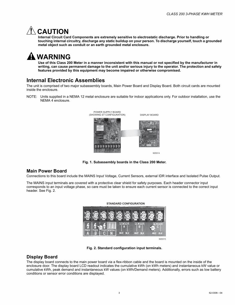
Internal Electronic AssembliesThe unit is comprised of two major subassembly boards, Main Power Board and Display Board. Both circuit cards are mounted inside the enclosure.
NOTE: Units supplied in a NEMA 12 metal enclosure are suitable for indoor applications only. For outdoor installation, use the NEMA 4 enclosure.
Fig. 1. Subassembly boards in the Class 200 Meter.
Main Power BoardConnections to this board include the MAINS Input Voltage, Current Sensors, external IDR interface and Isolated Pulse Output.
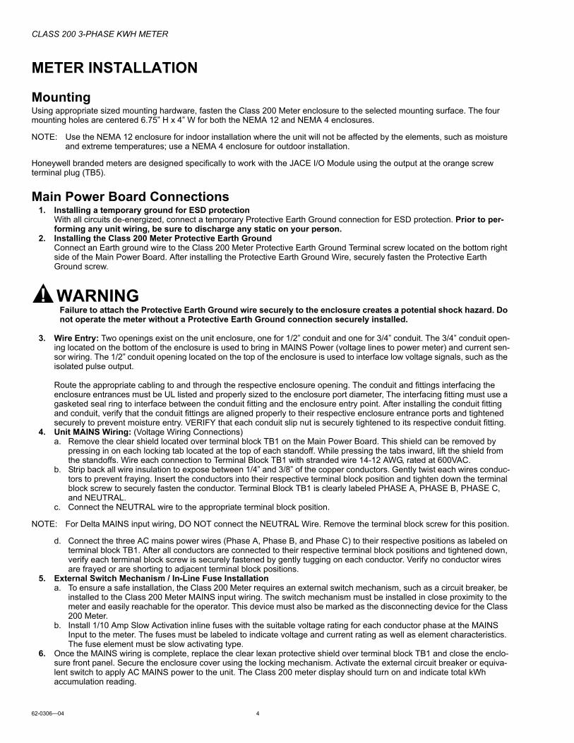
The MAINS input terminals are covered with a protective clear shield for safety purposes. Each header connector input corresponds to an input voltage phase, so care must be taken to ensure each current sensor is connected to the correct input header. See Fig. 2.
Fig. 2. Standard configuration input terminals.
Display BoardThe display board connects to the main power board via a flex-ribbon cable and the board is mounted on the inside of the enclosure door. The display board LCD readout indicates the cumulative kWh (on kWh meters) and instantaneous kW value or cumulative kWh, peak demand and instantaneous kW values (on kWh/Demand meters). Additionally, errors such as low battery conditions or sensor error conditions are displayed.
POWER SUPPLY BOARD(SHOWING ST CONFIGURATION)
M29314
DISPLAY BOARD
M29315
STANDARD CONFIGURATION
CLASS 200 3-PHASE KWH METER
62-0306—04 4
METER INSTALLATION
MountingUsing appropriate sized mounting hardware, fasten the Class 200 Meter enclosure to the selected mounting surface. The four mounting holes are centered 6.75” H x 4” W for both the NEMA 12 and NEMA 4 enclosures.
NOTE: Use the NEMA 12 enclosure for indoor installation where the unit will not be affected by the elements, such as moisture and extreme temperatures; use a NEMA 4 enclosure for outdoor installation.
Honeywell branded meters are designed specifically to work with the JACE I/O Module using the output at the orange screw terminal plug (TB5).
Main Power Board Connections1. Installing a temporary ground for ESD protection
With all circuits de-energized, connect a temporary Protective Earth Ground connection for ESD protection. Prior to per-forming any unit wiring, be sure to discharge any static on your person.
2. Installing the Class 200 Meter Protective Earth GroundConnect an Earth ground wire to the Class 200 Meter Protective Earth Ground Terminal screw located on the bottom right side of the Main Power Board. After installing the Protective Earth Ground Wire, securely fasten the Protective Earth Ground screw.
WARNINGFailure to attach the Protective Earth Ground wire securely to the enclosure creates a potential shock hazard. Do not operate the meter without a Protective Earth Ground connection securely installed.
3. Wire Entry: Two openings exist on the unit enclosure, one for 1/2” conduit and one for 3/4” conduit. The 3/4” conduit open-ing located on the bottom of the enclosure is used to bring in MAINS Power (voltage lines to power meter) and current sen-sor wiring. The 1/2” conduit opening located on the top of the enclosure is used to interface low voltage signals, such as the isolated pulse output.
Route the appropriate cabling to and through the respective enclosure opening. The conduit and fittings interfacing the enclosure entrances must be UL listed and properly sized to the enclosure port diameter, The interfacing fitting must use a gasketed seal ring to interface between the conduit fitting and the enclosure entry point. After installing the conduit fitting and conduit, verify that the conduit fittings are aligned properly to their respective enclosure entrance ports and tightened securely to prevent moisture entry. VERIFY that each conduit slip nut is securely tightened to its respective conduit fitting.
4. Unit MAINS Wiring: (Voltage Wiring Connections)a. Remove the clear shield located over terminal block TB1 on the Main Power Board. This shield can be removed by
pressing in on each locking tab located at the top of each standoff. While pressing the tabs inward, lift the shield from the standoffs. Wire each connection to Terminal Block TB1 with stranded wire 14-12 AWG, rated at 600VAC.
b. Strip back all wire insulation to expose between 1/4” and 3/8” of the copper conductors. Gently twist each wires conduc-tors to prevent fraying. Insert the conductors into their respective terminal block position and tighten down the terminal block screw to securely fasten the conductor. Terminal Block TB1 is clearly labeled PHASE A, PHASE B, PHASE C, and NEUTRAL.
c. Connect the NEUTRAL wire to the appropriate terminal block position.
NOTE: For Delta MAINS input wiring, DO NOT connect the NEUTRAL Wire. Remove the terminal block screw for this position.
d. Connect the three AC mains power wires (Phase A, Phase B, and Phase C) to their respective positions as labeled on terminal block TB1. After all conductors are connected to their respective terminal block positions and tightened down, verify each terminal block screw is securely fastened by gently tugging on each conductor. Verify no conductor wires are frayed or are shorting to adjacent terminal block positions.
5. External Switch Mechanism / In-Line Fuse Installationa. To ensure a safe installation, the Class 200 Meter requires an external switch mechanism, such as a circuit breaker, be
installed to the Class 200 Meter MAINS input wiring. The switch mechanism must be installed in close proximity to the meter and easily reachable for the operator. This device must also be marked as the disconnecting device for the Class 200 Meter.
b. Install 1/10 Amp Slow Activation inline fuses with the suitable voltage rating for each conductor phase at the MAINS Input to the meter. The fuses must be labeled to indicate voltage and current rating as well as element characteristics. The fuse element must be slow activating type.
6. Once the MAINS wiring is complete, replace the clear lexan protective shield over terminal block TB1 and close the enclo-sure front panel. Secure the enclosure cover using the locking mechanism. Activate the external circuit breaker or equiva-lent switch to apply AC MAINS power to the unit. The Class 200 meter display should turn on and indicate total kWh accumulation reading.
CLASS 200 3-PHASE KWH METER
5 62-0306—04
NOTE: The unit display, clock and other critical configuration parameters will be reset once the unit installation and wiring is complete.
7. Using an AC Voltmeter, verify the input voltage readings are within the limits specified below.
NOTE: For 3-wire systems, the voltages are measured Phase to Phase. On 4-wire systems, the voltages are measured Phase to Neutral.
8. Remove power from the unit by de-energizing the external switch.
Current Sensor Installation and WiringOnce the AC voltages have been confirmed to be within acceptable limits, you are ready to install the current sensors. The MAIN power board contains a 10-position terminal block (TB1) (standard configuration). The current sensors are connected to the 6 positions on the right side and marked with the appropriate phase designation and conductor color. This format must be followed in order for the meter to function correctly.
The class 200 meter will be used with split-core current sensors. A split-core sensor opens so that it can be attached around the circuit conductor being monitored without interrupting power.
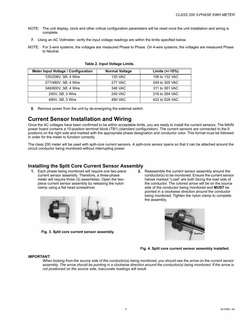
Installing the Split Core Current Sensor Assembly1. Each phase being monitored will require one two-piece
current sensor assembly. Therefore, a three-phase meter will require three (3) assemblies. Open the two-piece current sensor assembly by releasing the nylon clamp using a flat head screwdriver.
Fig. 3. Split core current sensor assembly.
2. Reassemble the current sensor assembly around the conductor(s) to be monitored. Ensure the current sensor halves marked “Load” are both facing the load side of the conductor. The colored arrow will be on the source side of the conductor being monitored and MUST be pointed in a clockwise direction around the conductor being monitored. Tighten the nylon clamp to complete the assembly.
Fig. 4. Split core current sensor assembly installed.
IMPORTANT:When looking from the source side of the conductor(s) being monitored, you should see the arrow on the current sensor assembly. The arrow should be pointing in a clockwise direction around the conductor(s) being monitored. If the arrow is not positioned on the source side, inaccurate readings will result.
Table 2. Input Voltage Limits.
Meter Input Voltage / Configuration Normal Voltage Limits (+/-10%)
120/208V, 3Ø, 4 Wire 120 VAC 108 to 132 VAC
277/480V, 3Ø, 4 Wire 277 VAC 249 to 305 VAC
346/600V, 3Ø, 4 Wire 346 VAC 311 to 381 VAC
240V, 3Ø, 3 Wire 240 VAC 216 to 264 VAC
480V, 3Ø, 3 Wire 480 VAC 432 to 528 VAC
CLASS 200 3-PHASE KWH METER
62-0306—04 6
Current Sensor WiringOnce all the current sensors are installed on their appropriate phase conductors, you can begin terminating the current sensors on to the Class 200 main power board.
The current sensor leads can be extended up to 2,000 feet (using #14-22 AWG wire) for remote monitoring applications. Consult your local electrical codes for proper wire sizing (#22 AWG twisted pair wire with a black and white conductor, rated for 600 VAC recommended.)
The current sensor connection points are located on the bottom center of the main power board. If supplied with the terminal block (TB1) (standard configuration), the current sensors are connected to the 6 positions on the right side.
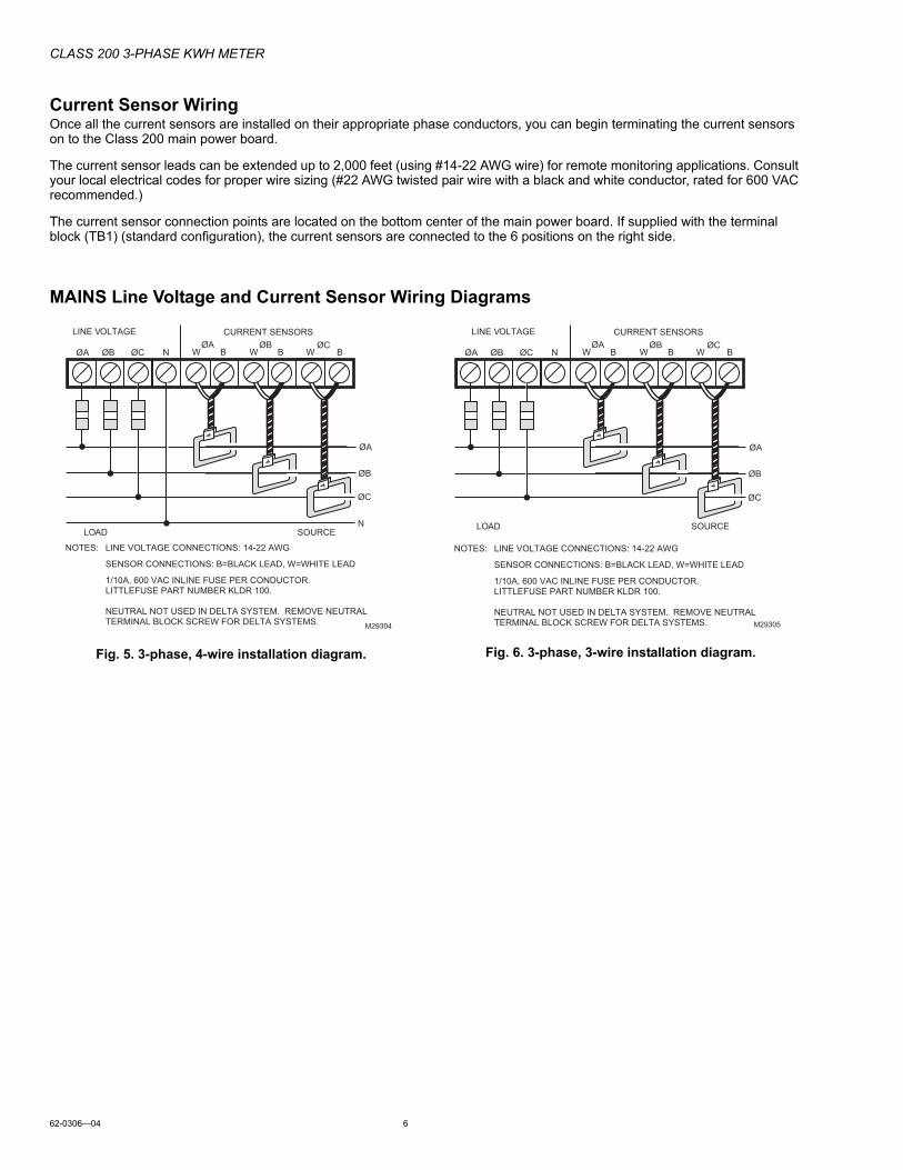
MAINS Line Voltage and Current Sensor Wiring Diagrams
Fig. 5. 3-phase, 4-wire installation diagram. Fig. 6. 3-phase, 3-wire installation diagram.
W B N
LINE VOLTAGE
ØA
ØC
LOAD SOURCE
ØBW B
M29304
ØAØA ØB ØC
ØB
W B
CURRENT SENSORSØC
N
NOTES: LINE VOLTAGE CONNECTIONS: 14-22 AWG SENSOR CONNECTIONS: B=BLACK LEAD, W=WHITE LEAD 1/10A, 600 VAC INLINE FUSE PER CONDUCTOR. LITTLEFUSE PART NUMBER KLDR 100.
NEUTRAL NOT USED IN DELTA SYSTEM. REMOVE NEUTRAL TERMINAL BLOCK SCREW FOR DELTA SYSTEMS.
W B N
LINE VOLTAGE
ØA
ØC
LOAD SOURCE
ØBW B
M29305
ØAØA ØB ØC
ØB
W B
CURRENT SENSORSØC
NOTES: LINE VOLTAGE CONNECTIONS: 14-22 AWG SENSOR CONNECTIONS: B=BLACK LEAD, W=WHITE LEAD 1/10A, 600 VAC INLINE FUSE PER CONDUCTOR. LITTLEFUSE PART NUMBER KLDR 100.
NEUTRAL NOT USED IN DELTA SYSTEM. REMOVE NEUTRAL TERMINAL BLOCK SCREW FOR DELTA SYSTEMS.
CLASS 200 3-PHASE KWH METER
7 62-0306—04
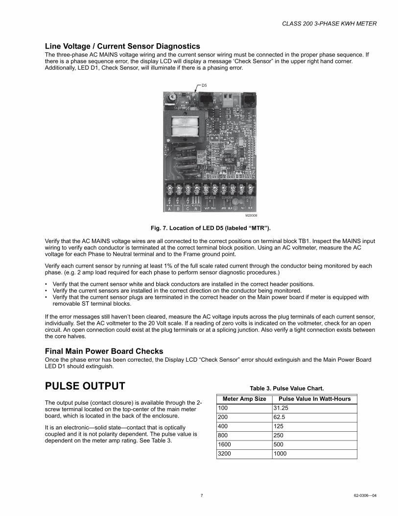
Line Voltage / Current Sensor DiagnosticsThe three-phase AC MAINS voltage wiring and the current sensor wiring must be connected in the proper phase sequence. If there is a phase sequence error, the display LCD will display a message ‘Check Sensor” in the upper right hand corner. Additionally, LED D1, Check Sensor, will illuminate if there is a phasing error.
Fig. 7. Location of LED D5 (labeled “MTR”).
Verify that the AC MAINS voltage wires are all connected to the correct positions on terminal block TB1. Inspect the MAINS input wiring to verify each conductor is terminated at the correct terminal block position. Using an AC voltmeter, measure the AC voltage for each Phase to Neutral terminal and to the Frame ground point.
Verify each current sensor by running at least 1% of the full scale rated current through the conductor being monitored by each phase. (e.g. 2 amp load required for each phase to perform sensor diagnostic procedures.)
• Verify that the current sensor white and black conductors are installed in the correct header positions.• Verify the current sensors are installed in the correct direction on the conductor being monitored.• Verify that the current sensor plugs are terminated in the correct header on the Main power board if meter is equipped with
removable ST terminal blocks.
If the error messages still haven’t been cleared, measure the AC voltage inputs across the plug terminals of each current sensor, individually. Set the AC voltmeter to the 20 Volt scale. If a reading of zero volts is indicated on the voltmeter, check for an open circuit. An open connection could exist at the plug terminals or at a splicing junction. Also verify a tight connection exists between the core halves.
Final Main Power Board ChecksOnce the phase error has been corrected, the Display LCD “Check Sensor” error should extinguish and the Main Power Board LED D1 should extinguish.
PULSE OUTPUT
The output pulse (contact closure) is available through the 2-screw terminal located on the top-center of the main meter board, which is located in the back of the enclosure.
It is an electronic—solid state—contact that is optically coupled and it is not polarity dependent. The pulse value is dependent on the meter amp rating. See Table 3.
D5
M29306
Table 3. Pulse Value Chart.
Meter Amp Size Pulse Value In Watt-Hours
100 31.25
200 62.5
400 125
800 250
1600 500
3200 1000
CLASS 200 3-PHASE KWH METER
62-0306—04 8
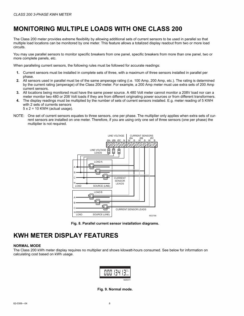
MONITORING MULTIPLE LOADS WITH ONE CLASS 200
The Class 200 meter provides extreme flexibility by allowing additional sets of current sensors to be used in parallel so that multiple load locations can be monitored by one meter. This feature allows a totalized display readout from two or more load circuits.
You may use parallel sensors to monitor specific breakers from one panel, specific breakers from more than one panel, two or more complete panels, etc.
When paralleling current sensors, the following rules must be followed for accurate readings:
1. Current sensors must be installed in complete sets of three, with a maximum of three sensors installed in parallel per phase.
2. All sensors used in parallel must be of the same amperage rating (i.e. 100 Amp, 200 Amp, etc.). The rating is determined by the current rating (amperage) of the Class 200 meter. For example, a 200 Amp meter must use extra sets of 200 Amp current sensors.
3. All locations being monitored must have the same power source. A 480 Volt meter cannot monitor a 208V load nor can a meter monitor two 480 or 208 Volt loads if they are from different originating power sources or from different transformers.
4. The display readings must be multiplied by the number of sets of current sensors installed. E.g. meter reading of 5 KWH with 2 sets of currents sensors5 x 2 = 10 KWH (actual usage).
NOTE: One set of current sensors equates to three sensors, one per phase. The multiplier only applies when extra sets of cur-rent sensors are installed on one meter. Therefore, if you are using only one set of three sensors (one per phase) the multiplier is not required.
Fig. 8. Parallel current sensor installation diagrams.
KWH METER DISPLAY FEATURES
NORMAL MODEThe Class 200 kWh meter display requires no multiplier and shows kilowatt-hours consumed. See below for information on calculating cost based on kWh usage.
Fig. 9. Normal mode.
LOAD SOURCE (LINE)
LINE VOLTAGE
A
B
C
N
ØA ØB ØC N W B W B W BØB
LOAD SOURCE (LINE)
A
B
C
N
LOAD A
CURRENT SENSOR LEADS
CURRENTSENSORLEADS
LINE VOLTAGELEADS
CURRENT SENSORS
M32796
ØCØA
LOAD B
M29311
KWH
››››››CHECKSENSOR
CLASS 200 3-PHASE KWH METER
9 62-0306—04
KW LOAD MODE (CURRENT LOAD IN KW)Pressing the “UP” button on the meter display board will switch the display to the Load mode and will show the present load in kW (kilowatts). (Allow 6 seconds for correct reading to stabilize.) This feature is useful to the consumer as it shows the actual load on the meter and can be valuable in showing the effects of large loads-such as air conditioning, electric hot water heaters, and electrical appliances on power consumption. Pressing the “UP” button again returns the meter display to normal mode.
Fig. 10. KW load mode.
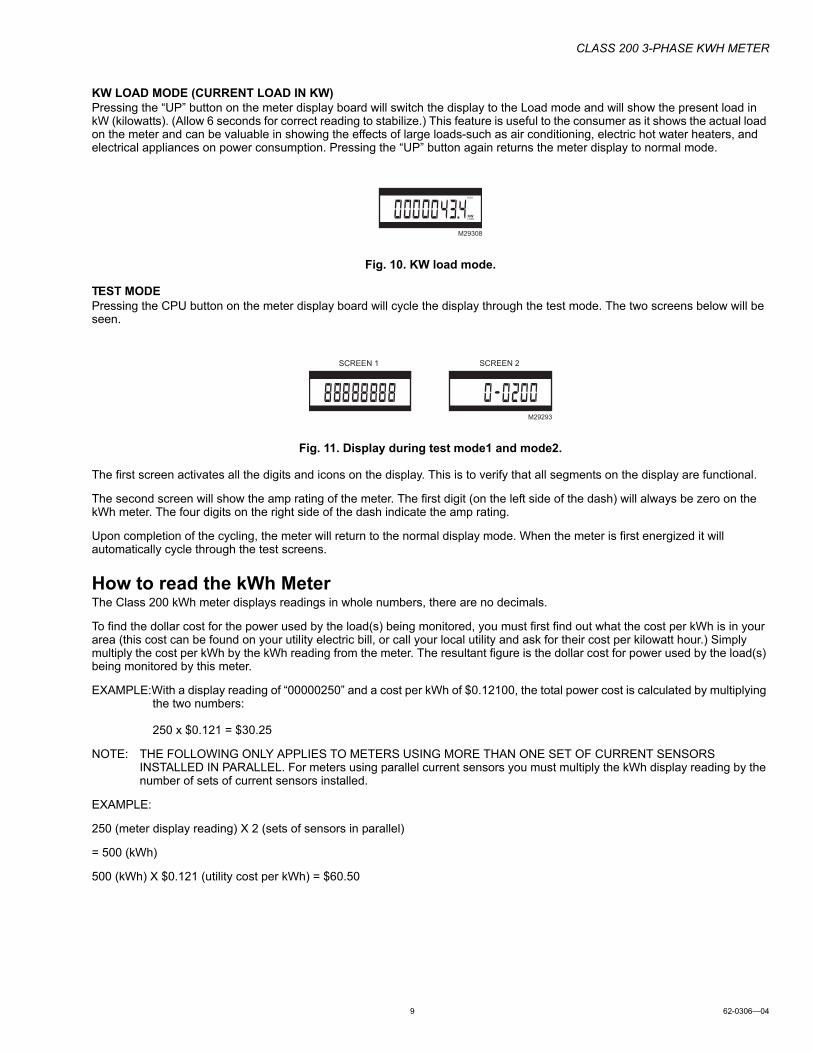
TEST MODEPressing the CPU button on the meter display board will cycle the display through the test mode. The two screens below will be seen.
Fig. 11. Display during test mode1 and mode2.
The first screen activates all the digits and icons on the display. This is to verify that all segments on the display are functional.
The second screen will show the amp rating of the meter. The first digit (on the left side of the dash) will always be zero on the kWh meter. The four digits on the right side of the dash indicate the amp rating.
Upon completion of the cycling, the meter will return to the normal display mode. When the meter is first energized it will automatically cycle through the test screens.
How to read the kWh MeterThe Class 200 kWh meter displays readings in whole numbers, there are no decimals.
To find the dollar cost for the power used by the load(s) being monitored, you must first find out what the cost per kWh is in your area (this cost can be found on your utility electric bill, or call your local utility and ask for their cost per kilowatt hour.) Simply multiply the cost per kWh by the kWh reading from the meter. The resultant figure is the dollar cost for power used by the load(s) being monitored by this meter.
EXAMPLE:With a display reading of “00000250” and a cost per kWh of $0.12100, the total power cost is calculated by multiplying the two numbers:
250 x $0.121 = $30.25
NOTE: THE FOLLOWING ONLY APPLIES TO METERS USING MORE THAN ONE SET OF CURRENT SENSORS INSTALLED IN PARALLEL. For meters using parallel current sensors you must multiply the kWh display reading by the number of sets of current sensors installed.
EXAMPLE:
250 (meter display reading) X 2 (sets of sensors in parallel)
= 500 (kWh)
500 (kWh) X $0.121 (utility cost per kWh) = $60.50
M29308
KWLOAD
››››››
SCREEN 1 SCREEN 2
M29293
CLASS 200 3-PHASE KWH METER
62-0306—04 10
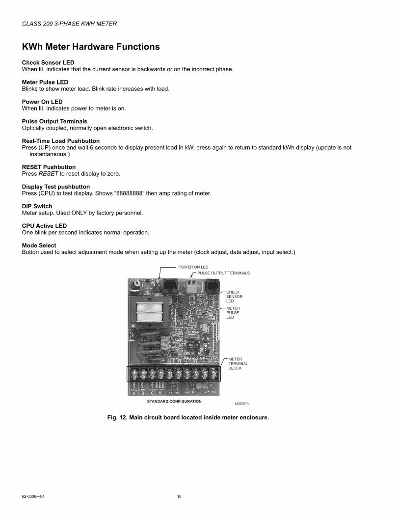
KWh Meter Hardware Functions
Check Sensor LEDWhen lit, indicates that the current sensor is backwards or on the incorrect phase.
Meter Pulse LEDBlinks to show meter load. Blink rate increases with load.
Power On LEDWhen lit, indicates power to meter is on.
Pulse Output TerminalsOptically coupled, normally open electronic switch.
Real-Time Load PushbuttonPress (UP) once and wait 6 seconds to display present load in kW, press again to return to standard kWh display (update is not
instantaneous.)
RESET PushbuttonPress RESET to reset display to zero.
Display Test pushbuttonPress (CPU) to test display. Shows “88888888” then amp rating of meter.
DIP SwitchMeter setup. Used ONLY by factory personnel.
CPU Active LEDOne blink per second indicates normal operation.
Mode SelectButton used to select adjustment mode when setting up the meter (clock adjust, date adjust, input select.)
Fig. 12. Main circuit board located inside meter enclosure.
METERTERMINALBLOCK
M29291A
POWER ON LED
METERPULSELED
CHECK SENSORLED
PULSE OUTPUT TERMINALS
STANDARD CONFIGURATION
CLASS 200 3-PHASE KWH METER
11 62-0306—04
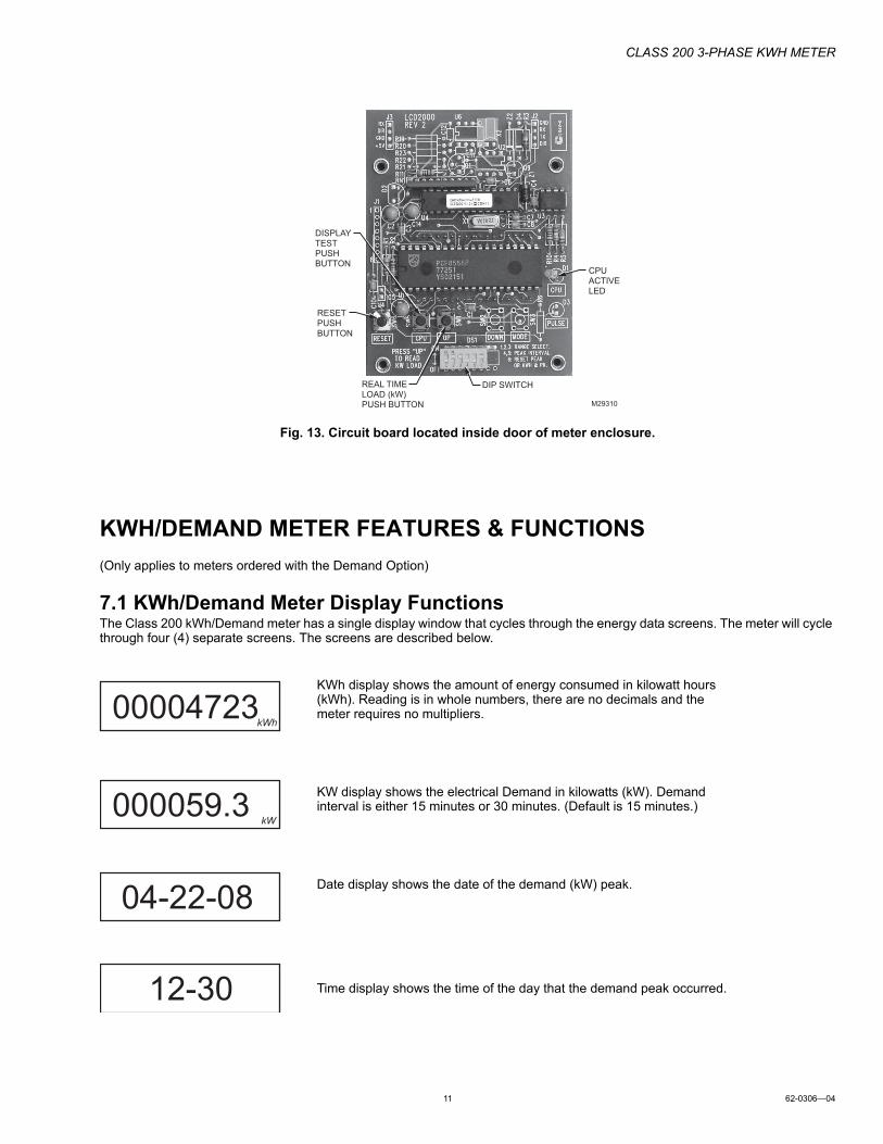
Fig. 13. Circuit board located inside door of meter enclosure.
KWH/DEMAND METER FEATURES & FUNCTIONS
(Only applies to meters ordered with the Demand Option)
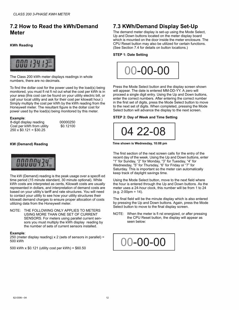
7.1 KWh/Demand Meter Display FunctionsThe Class 200 kWh/Demand meter has a single display window that cycles through the energy data screens. The meter will cycle through four (4) separate screens. The screens are described below.
M29310
DIP SWITCH
CPUACTIVELED
RESETPUSHBUTTON
DISPLAYTESTPUSHBUTTON
REAL TIMELOAD (kW)PUSH BUTTON
00004723kWh
000059.3kW
04-22-08
12-30
KWh display shows the amount of energy consumed in kilowatt hours (kWh). Reading is in whole numbers, there are no decimals and the meter requires no multipliers.
KW display shows the electrical Demand in kilowatts (kW). Demand interval is either 15 minutes or 30 minutes. (Default is 15 minutes.)
Date display shows the date of the demand (kW) peak.
Time display shows the time of the day that the demand peak occurred.
CLASS 200 3-PHASE KWH METER
62-0306—04 12
7.2 How to Read the kWh/Demand Meter
KWh Reading
The Class 200 kWh meter displays readings in whole numbers, there are no decimals.
To find the dollar cost for the power used by the load(s) being monitored, you must fi rst fi nd out what the cost per kWh is in your area (this cost can be found on your utility electric bill, or call your local utility and ask for their cost per kilowatt hour.) Simply multiply the cost per kWh by the kWh reading from the Honeywell meter. The resultant figure is the dollar cost for power used by the load(s) being monitored by this meter.
Example:8-digit display reading 00000250Cost per kWh from utility $0.12100250 x $0.121 = $30.25
KW (Demand) Reading
The kW (Demand) reading is the peak usage over a specifi ed time period (15 minute standard, 30 minute optional). While kWh costs are interpreted as cents, Kilowatt costs are usually represented in dollars, and interpretation of demand costs are based on your utility’s tariff and rate structures. You will need to contact your utility to see how your utility structures their kilowatt demand charges to ensure proper allocation of costs utilizing data from the Honeywell meter.
NOTE: THE FOLLOWING ONLY APPLIES TO METERS USING MORE THAN ONE SET OF CURRENT SENSORS. For meters using parallel current sen-sors you must multiply the kWh display reading by the number of sets of current sensors installed.
Example:250 (meter display reading) x 2 (sets of sensors in parallel) = 500 kWh
500 kWh x $0.121 (utility cost per kWh) = $60.50
7.3 KWh/Demand Display Set-UpThe demand meter display is set-up using the Mode Select, Up and Down buttons located on the meter display board which is mounted on the door inside the meter enclosure. The CPU Reset button may also be utilized for certain functions. (See Section 7.4 for details on button locations.)
STEP 1: Date Setting
Press the Mode Select button and the display screen shown will appear. The date is entered MM-DD-YY. A zero will proceed a single digit entry. Using the Up and Down buttons, enter the correct numbers. After entering the correct number in the first set of digits, press the Mode Select button to move to the next set of digits. When completed, pressing the Mode Select button will advance the display to the next screen.
STEP 2: Day of Week and Time Setting
The first section of the next screen calls for the entry of the recent day of the week. Using the Up and Down buttons, enter “1” for Sunday, “2” for Monday, “3” for Tuesday, “4” for Wednesday, “5” for Thursday, “6” for Friday or “7” for Saturday. This is important so the meter can automatically keep track of daylight savings time.
Using the Mode Select button, move to the next field where the hour is entered through the Up and Down buttons. As the meter uses a 24-hour clock, this number will be from 1 to 24 (e.g. 2:00pm = 14).
The final field will be the minute display which is also entered by pressing the Up and Down buttons. Again, press the Mode Select button to move to the final display screen.
NOTE: When the meter is fi rst energized, or after pressing the CPU Reset button, the display will appear as seen below:
04 22-08
Time shown is Wednesday, 10:08 pm
00-00-00
00-00-00
CLASS 200 3-PHASE KWH METER
13 62-0306—04
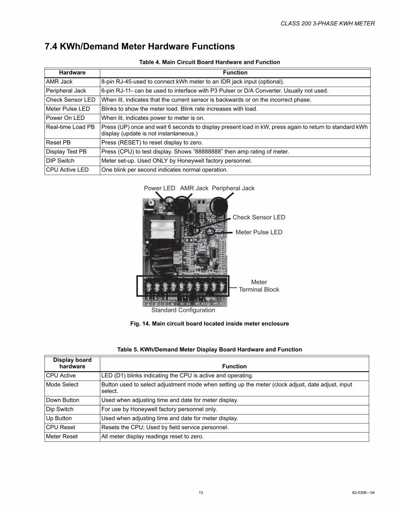
7.4 KWh/Demand Meter Hardware Functions
Table 4. Main Circuit Board Hardware and Function
Fig. 14. Main circuit board located inside meter enclosure
Table 5. KWh/Demand Meter Display Board Hardware and Function
Hardware Function
AMR Jack 8-pin RJ-45-used to connect kWh meter to an IDR jack input (optional).
Peripheral Jack 6-pin RJ-11- can be used to interface with P3 Pulser or D/A Converter. Usually not used.
Check Sensor LED When lit, indicates that the current sensor is backwards or on the incorrect phase.
Meter Pulse LED Blinks to show the meter load. Blink rate increases with load.
Power On LED When lit, indicates power to meter is on.
Real-time Load PB Press (UP) once and wait 6 seconds to display present load in kW, press again to return to standard kWh display (update is not instantaneous.)
Reset PB Press (RESET) to reset display to zero.
Display Test PB Press (CPU) to test display. Shows “88888888” then amp rating of meter.
DIP Switch Meter set-up. Used ONLY by Honeywell factory personnel.
CPU Active LED One blink per second indicates normal operation.
MeterTerminal Block
Check Sensor LED
Meter Pulse LED
Power LED AMR Jack Peripheral Jack
Standard Confi guration
Display board hardware Function
CPU Active LED (D1) blinks indicating the CPU is active and operating.
Mode Select Button used to select adjustment mode when setting up the meter (clock adjust, date adjust, input select.
Down Button Used when adjusting time and date for meter display.
Dip Switch For use by Honeywell factory personnel only.
Up Button Used when adjusting time and date for meter display.
CPU Reset Resets the CPU; Used by field service personnel.
Meter Reset All meter display readings reset to zero.
CLASS 200 3-PHASE KWH METER
62-0306—04 14
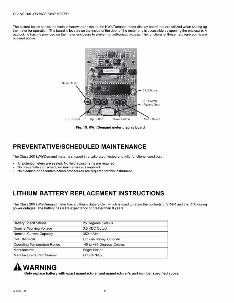
The picture below shows the various hardware points on the KWh/Demand meter display board that are utilized when setting up the meter for operation. The board is located on the inside of the door of the meter and is accessible by opening the enclosure. A padlocking hasp is provided on the meter enclosure to prevent unauthorized access. The functions of these hardware points are outlined above.
Fig. 15. KWh/Demand meter display board
PREVENTATIVE/SCHEDULED MAINTENANCE
The Class 200 kWh/Demand meter is shipped in a calibrated, tested and fully functional condition.
• All potentiometers are sealed. No field adjustments are required.• No preventative or scheduled maintenance is required.• No cleaning or decontamination procedures are required for this instrument.
LITHIUM BATTERY REPLACEMENT INSTRUCTIONS
The Class 200 kWh/Demand meter has a Lithium Battery Cell, which is used to retain the contents of SRAM and the RTC during power outages. The battery has a life expectancy of greater than 8 years.
WARNINGOnly replace battery with exact manufacturer and manufacturer’s part number specified above.
Meter Reset
CPU Active
DIP Switch(Factory Set)
CPU Reset Up Button Down Button Mode Select
Battery Specifications 25 Degrees Celsius
Nominal Working Voltage 3.5 VDC Output
Nominal Current Capacity 350 mAHr
Cell Chemical Lithium-Thionyl Chloride
Operating Temperature Range -40 to +95 Degrees Celsius
Manufacturer Eagle-Picher
Manufacturer’s Part Number LTC-3PN-S2
CLASS 200 3-PHASE KWH METER
15 62-0306—04
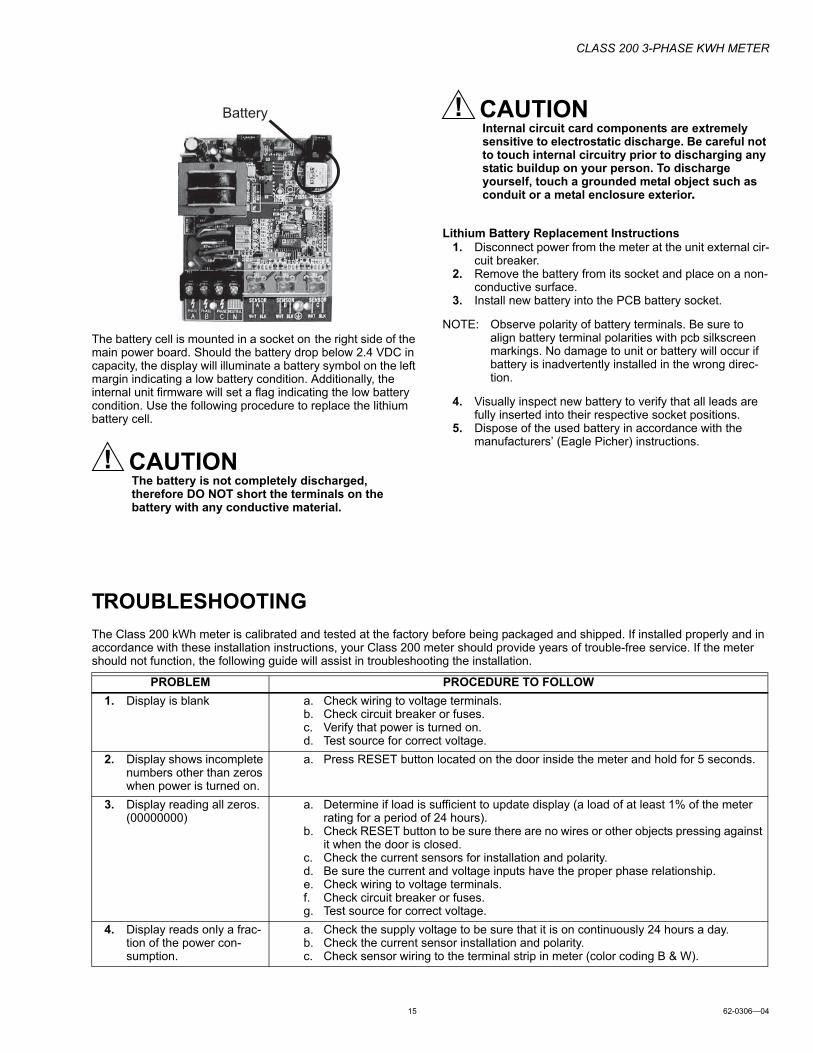
The battery cell is mounted in a socket on the right side of the main power board. Should the battery drop below 2.4 VDC in capacity, the display will illuminate a battery symbol on the left margin indicating a low battery condition. Additionally, the internal unit firmware will set a flag indicating the low battery condition. Use the following procedure to replace the lithium battery cell.
CAUTIONThe battery is not completely discharged, therefore DO NOT short the terminals on the battery with any conductive material.
CAUTIONInternal circuit card components are extremely sensitive to electrostatic discharge. Be careful not to touch internal circuitry prior to discharging any static buildup on your person. To discharge yourself, touch a grounded metal object such as conduit or a metal enclosure exterior.
Lithium Battery Replacement Instructions 1. Disconnect power from the meter at the unit external cir-
cuit breaker.2. Remove the battery from its socket and place on a non-
conductive surface.3. Install new battery into the PCB battery socket.
NOTE: Observe polarity of battery terminals. Be sure to align battery terminal polarities with pcb silkscreen markings. No damage to unit or battery will occur if battery is inadvertently installed in the wrong direc-tion.
4. Visually inspect new battery to verify that all leads are fully inserted into their respective socket positions.
5. Dispose of the used battery in accordance with the manufacturers’ (Eagle Picher) instructions.
TROUBLESHOOTING
The Class 200 kWh meter is calibrated and tested at the factory before being packaged and shipped. If installed properly and in accordance with these installation instructions, your Class 200 meter should provide years of trouble-free service. If the meter should not function, the following guide will assist in troubleshooting the installation.
Battery
PROBLEM PROCEDURE TO FOLLOW
1. Display is blank a. Check wiring to voltage terminals.b. Check circuit breaker or fuses.c. Verify that power is turned on.d. Test source for correct voltage.
2. Display shows incomplete numbers other than zeros when power is turned on.
a. Press RESET button located on the door inside the meter and hold for 5 seconds.
3. Display reading all zeros. (00000000)
a. Determine if load is sufficient to update display (a load of at least 1% of the meter rating for a period of 24 hours).
b. Check RESET button to be sure there are no wires or other objects pressing against it when the door is closed.
c. Check the current sensors for installation and polarity.d. Be sure the current and voltage inputs have the proper phase relationship.e. Check wiring to voltage terminals.f. Check circuit breaker or fuses.g. Test source for correct voltage.
4. Display reads only a frac-tion of the power con-sumption.
a. Check the supply voltage to be sure that it is on continuously 24 hours a day.b. Check the current sensor installation and polarity.c. Check sensor wiring to the terminal strip in meter (color coding B & W).
CLASS 200 3-PHASE KWH METER
Automation and Control Solutions
Honeywell International Inc.
1985 Douglas Drive North
Golden Valley, MN 55422
customer.honeywell.com® U.S. Registered Trademark© 2011 Honeywell International Inc.62-0306—04 M.S. Rev. 06-11 Printed in U.S.A.
FREQUENTLY ASKED QUESTIONS
Q. When providing line voltage to the Class 200 Meter, can I tap off of the same breaker I am monitoring?A. Yes, the voltage can be pulled from the same breaker being monitored.
Q. Can the Class 200 Meter line voltage wires be run in the same conduit as the sensor leads?A. Yes, there will be no effect on the Class 200 Meter if the sensor leads and line voltage wires are run in the same conduit.
Q. Can the meter communication wires and line voltage wires be run in the same conduit?A. It is NOT recommended to run these wires together due to noise concerns and their effects on the communications signal
integrity. Communication wires can be routed separately using the 1/2” conduit port.
Q. How do I find the cost for kWh and kW to bill my tenants?A. Your local utility bill should list the cost per kWh and kW. If not, simply call your utility and ask them to provide you with the
cost per kWh and kW.
Q. What size wire do I use for the line voltage leads?A. These wires are normally sized at #14 AWG, but be sure to confirm this requirement with your local and national electrical
codes requirements.
Q. What size wire should I use to extend the current sensor leads?A. These wires are normally #14 AWG, twisted pair arrangement. Consult your local electrical code for proper sizing
requirements.
Q. The load I need to monitor has parallel feeds. How do I install the current sensors for this application?A. There are two ways you can monitor parallel feeds. One method is to clamp the sensors around all feed wires for each
phase. The second way to monitor parallel feeds is to clamp the sensor around one of the feed wires for each phase. When you read the Class 200, the final reading must be multiplied by the number of feed wires for each phase.
Q. I have two subpanels I would like to monitor with one Class 200 Meter. These subpanels are fed by different transformers in the building. Can I parallel sensors and monitor both panels with one Class 200 Meter?
A. No. These panels cannot be monitored by one Class 200 because they are different power sources. When you parallel current sensors, all loads being monitored must be from the same voltage source.