Embed Size (px)
Citation preview

1
6606 Tussing Road – P.O. Box 4009
Reynoldsburg, Ohio 43068-9009
(614) 644-3153 FAX (614) 995-1146
Backflow Prevention & Cross-Connection Control Manual For the Education of Ohio Certified Backflow Prevention Technicians
Administered by:
The Ohio Department of Commerce, Industrial Compliance, Backflow Section.

2
Manual Development Sponsored By:
Ohio Department of Commerce
Ohio Department of Health
Ohio Environmental Protection Agency
Ohio Rural Water Association
Operator Training Committee of Ohio, Incorporated
Ohio Section, American Water Works Association
Original Manual Development Committee:
David Bornino, Ohio Environmental Protection Agency
Frank Czako, APHC Backflow School
Rick Eberle, Ohio Section, American Waterworks Association
Ron Graves, Plumbers, Pipefitters and Service Technicians Local 189 JATC
Jess Jones, Operator Training Committee of Ohio, Inc.
Andy Provoznik, Ohio Rural Water association
Ralph Reeb, Ohio Department of Commerce
Terry Urbanek, Plumbers & Pipefitters Local 120
Jack Wormley, PHCC of Ohio
***IN MEMORY…a special appreciation and thanks to Jess Jones, Operator Training
Committee of Ohio Inc., for a lifetime commitment to the Water Purveyor and Backflow
Industries.***
***IN MEMORY…of Ralph Reeb, Plumbing Chief, Ohio Department of Commerce, Division
of Industrial Compliance.***
***IN MEMORY…of Jack Wormley, PHCC of Ohio.***

3
TABLE OF CONTENTS
Table of Contents …………………………………………………..3 About This Course …………………………………………………..4
Introduction …………………………………………………..5 Authority in Ohio …………………………………………………..6
Responsibility ……………………………………..……….…….7-9
Degree of Hazard ………………………………………………….10 Definitions ……………………………………………....11-17
Upstream vs Downstream …………………………………………………..18
Atmospheric Pressure ………………………………………….……….19-20
Pressure & Elevation Head …………………………………………………..21
Backsiphonage …………………………………………………..22 Backpressure …………………………………………………..22
Cross-Connections …………………………………………………..24
Venturi Principle ………………………………………...……..25-26 Air-Gap Separation …………………………………………………..27
ASSE 1013 …………………………………………………..28
ASSE 1015 …………………………………………………..29 ASSE 1001 ……………………………………...………..30-31
ASSE 1020 …………………………………………………..32-35
Installation Requirements …………………………………………………..36
Backflow Preventer Application …………………………………………………..37
Backflow Prevention Devices …………………………………………………..38-46
Backflow Application Chart …………………………………………………..47-49
Thermal Expansion Control …………………………………………………..50
Barometric Loop …………………………………………………..51 Auxiliary Water Sources …………………………………………………..52
Interchangeable Connectors …………………………………………………..53
Low-Suction Pressure Cut-Off …………………………………………………..54
Ohio Basic Building Code, Plumbing …………………………………………………..55-60
Specific BFP Applications …………………………………………………..61
Ohio Administrative Code, OEPA …………………………………………………..62-71
Policy on Use of Antifreeze …………………………………………………..72
Check List for Testers …………………………………………………..73
3-Vavle Analog Test Gauge …………………………………………………..74
ASSE 1013 Test Procedures …………………………………………………..75-76
ASSE 1015 Test Procedures …………………………………………………..77-78
ASSE 1020 Test Procedures …………………………………………………..79-80
ASSE 1056 Test Procedure …………………………………………………..81-82
5-Valve Analog Test Gauge …………………………………………………..83
ASSE 1013 Test Procedures …………………………………………………..84-85
ASSE 1015 Test Procedures …………………………………………………..86-87
ASSE 1020 Test Procedures …………………………………………………..88-89
ASSE 1056 Test Procedure …………………………………………………..90-91
Generic Test Form …………………………………………………..92
Test Gauge Recalibration …….…………………………………………….93
Tester Safety …………………………………………….….....94 RP Parts Drawing …………………………………………………..95
DC Parts Drawing …………………………………………………..96
PVB Parts Drawing …………………………………………..………97

4
OHIO DEPARTMENT OF COMMERCE BACKFLOW PREVENTION MANUAL
ABOUT THIS COURSE
This backflow prevention course is intended to prepare you to test/repair the various backflow
prevention devices that are used to protect the public water supply. The course consists of a
combined total of 24 hours of training in the classroom and the hands-on test lab.
This manual will be used as an instructional aid for the classroom portion of the course.
Your Instructor will conduct the hands-on portion of the course in the test lab. You will have the
opportunity to test, disassemble, reassemble and repair various backflow prevention devices.
You will be required to attend a Re-certification Course every three years to remain current,
however you may attend the re-certification course more frequently provided space is available in
the classes.
Your identification card will indicate the date that your certification expires or you can check the
date on the Internet at www.com.state.oh.us.
It is extremely important that a tester remember that after their expiration date they CANNOT test devices until they have taken a recertification course. Certified testers who have expired have a grace period in which they can attend a recertification class and bring their certification into active status.

OHIO DEPARTMENT OF COMMERCE BACKFLOW PREVENTION MANUAL
INTRODDUCTION
5
Backflow can be defined as the unintentional reversal of the normal direction of flow within a
piping system. When there are cross-connections in the consumer’s water distribution system,
either actual or potential cross-connections, a substance can be introduced into the piping.
Substances that may backflow into a potable water distribution system can be prevented from
entering the system through the proper application of an approved air-gap separation or any
number of other approved backflow prevention devices that are commercially available.
This manual is intended to make you aware of the hazard associated with a backflow condition
and the available methods and/or devices that may be used to properly protect the water
distribution system.
Additionally the information contained in this manual and your hands-on training during the class
will prepare you for the Ohio Department of Commerce “Backflow Technician” exam.
Successful completion of the training course and the written test will result in a State Certification
that is valid for a three year period.
Backflow prevention is a joint responsibility of the regulatory authorities, the local plumbing
inspection officials, the water supplier, and the consumer. Each has a role in the eliminating
the possibility of backflow.
You, the plumbing trades, are a primary figure in backflow prevention. You are the individual
who sees the problem first-hand and on-site. The owner, water supplier and plumbing inspector
will depend upon you to recognize a problem and bring it to their attention.

OHIO DEPARTMENT OF COMMERCE BACKFLOW PREVENTION MANUAL
AUTHORITY IN OHIO
6
In the State of Ohio there are two Regulatory Agencies that oversee the potable water supply.
The Ohio Environmental Protection Agency has the authority over the public water system from the
source to the service connection, which is defined in Ohio Administrative Code as the outlet side of
the water meter.
The water supplier acts as the enforcement officer for the Ohio EPA. The water supplier uses the
containment principle of backflow prevention to protect the public water supply from backflow. The
containment principle backflow prevention assembly remains under the authority of the water supplier
even though it may be installed inside the building.
The Ohio Department of Commerce, Industrial Compliance Division has the authority over the
consumer’s water distribution system, which begins at the water meter and includes all piping and
fixtures in the building.
The local plumbing official acts as the enforcement officer for the Ohio DOC. The plumbing official
uses the isolation principle of backflow prevention to protect the consumer’s water system.
If the water meter is installed inside the building then the containment principle backflow
preventer must be installed immediately after the water meter. If the meter is installed outside the
building then the containment principle backflow preventer is typically installed inside the
building wall unless otherwise approved by the water supplier.
Figure 1
Boiler
Sink
Drinking
Fountain
Isolation
Principle
Backflow
Preventer
Principle
Backflow
Main Water
Meter *
Ohio EPA Ohio DOC
Water Supplier Plumbing Inspection Department

OHIO DEPARTMENT OF COMMERCE BACKFLOW PREVENTION MANUAL
RESPONSIBILITY
7
The responsibility for backflow prevention rests jointly with the supplier of water, the water consumer,
the plumbing inspection agencies and the Regulatory Agencies. The Regulatory Agencies include the
Ohio Environmental Protection Agency and the Ohio Department of Commerce.
Backflow prevention may be divided into two areas of protection.
One is the protection of the public potable water system, which is the responsibility of the supplier of
water.
The other is the protection of the consumer’s potable water system, which is the responsibility of the
consumer-owner of the premises and the plumbing inspection agencies.
Supplier of Water
The supplier of water has the primary responsibility for providing the consumer with a safe and
potable water supply. This responsibility begins at the source, includes all of the public water
distribution system and service connections, and ends at the point of delivery to the consumer. The
point of delivery to the consumer is defined in the Ohio Administrative Code as the service connection
or the outlet side of the water meter.
The supplier of water must use reasonable care and vigilance to protect the public water system from
hazards originating within the consumer’s system that could contaminate the water in the public water
system.
The Water Consumer
The water consumer has the dual responsibility of protecting the water users within his own premises
and of protecting the public water system from contamination originating from conditions on the
premises. This responsibility begins at the service connection and includes the entire consumer’s
distribution system.
The water consumer is liable for any installation on his premises that could endanger the water quality
of either the public or consumer’s distribution system.

OHIO DEPARTMENT OF COMMERCE BACKFLOW PREVENTION MANUAL
RESPONSIBILITY
8
The Plumbing Inspection Authorities
The plumbing inspection authorities have a responsibility of inspecting the consumer’s water
distribution system to ensure that all cross-connections within the premises are protected from
backflow.
The plumbing inspection authorities are responsible for the inspection of the consumer’s potable water
system and ultimately share a liability with the owner and the design professional for the protection of
the internal water distribution system.
The plumbing inspection authorities meet this responsibility by inspecting all new construction to
ensure that all cross-connections are properly protected. They then must review the plans for all
plumbing permits to ensure that no new cross-connections are installed without the appropriate
protection.
The Regulatory Agencies
The regulatory agencies are responsible for enforcing Ohio’s laws, rules and regulations related to
backflow prevention.
The Ohio Department of Commerce oversees the plumbing inspection agencies, which have the
inspection authority and responsibility to protect the users within the premises.
The Ohio Environmental Protection Agency oversees the water suppliers, who have the authority and
responsibility to protect the integrity of the public water distribution system.

OHIO DEPARTMENT OF COMMERCE BACKFLOW PREVENTION MANUAL
RESPONSIBILITY
9
The Certified Technician’s Responsibility
The technician is responsible to properly test and report the status of each device tested and accurately
record the test results. He will furnish a copy of the test report to the owner or representative of the
owner, to the agency requiring the test, and a retain copy for their records.
*If the technician fails in this responsibility, fraudulently fills out the test report, fails to test a device
and reports it as tested, or other fraudulent activity in the testing and/or repairing of a device then there
will be an advisory committee meeting(s) to determine the seriousness of the activity and could result
in the action being taken as specified in the SUSPENSION GRID TABLE below.
It is the responsibility of the technician to be completely knowledgeable about regulations, rules or
requirements of the Ohio Regulatory Agencies and local authorities that may be required as to
registrations, requirements or additional certifications to work on specific systems before performing
the testing and repair of the backflow devices.
*The technician shall review the installation of a new or existing backflow prevention device to
determine that it is correct and if the device is capable of discharging water shall review the drainage
system to which it discharges to determine if the drain line(s) are capable of draining said discharge
completely and recording same as a comment. The comment notation should clearly indicate whether
or not the drainage line(s) is capable of handling this volume of discharge without causing flooding or
other damage and responsible parties should be put on notice of a design problem where damage of
any nature could occur because of said discharge.
*The following table is the mandatory penalties for falsification of backflow testing documentation.
*SUSPENSION GRID FALSIFICATION OF DOCUMENTATION
1st Offense 12 Month Suspension & Attend Recertification Class
2nd Offense 24 Month Suspension & Attend Full Certification Class No reexamination required
3rd Offense Lifetime Suspension of Certification
*These are penalties that are assessed by the Department of Commerce and are separate from any that can or will be assessed by the Ohio EPA in their investigation of the allegations of falsification of documentation when it involves the containment backflow device.

10
OHIO DEPARTMENT OF COMMERCE BACKFLOW PREVENTION MANUAL DEGREE OF HAZARD
The type of backflow prevention device that will be required at the water meter or at an
individual fixture is determined by evaluating the degree of hazard that is presented.
When we speak of evaluating the degree of hazard, we are going to determine the
potential for backflow to occur (can backflow happen) and the toxicity of the contaminant
that could backflow (how toxic is the substance that can backflow into the piping).
The Plumbing Inspection Authority under the direction of the Ohio Department of Commerce
determines the degree of hazard presented by the individual fixtures within the premises. Based
upon this evaluation, they determine the appropriate isolation principle backflow prevention
device that must be installed at the fixture.
The Water Supplier under the direction of the Ohio Environmental Protection Agency
determines the total degree of hazard presented by the premises and determines the appropriate
containment principle backflow prevention assembly that must be installed at the water meter.
Although the Ohio Department of Commerce and Ohio Environmental Protection Agency has
different levels of degree of hazard, there is a correlation between the two agencies as indicated
in the following chart.
Degree of Hazard Evaluation Terms
Ohio Department of Commerce Ohio Environmental Protection Agency
Low Hazard = Pollution Hazard (aesthetically objectionable)
High Hazard = System Hazard (may cause damage to the system piping)
“ = Health Hazard (is a threat to the health of the water user)
Severe High Hazard = Severe Health Hazard (presents a threat of death)
With a recommendation for an
approved air-gap separation:
1. Pump packing gland seal on
a sewage lift pump
2. Any system containing
ethylene glycol antifreeze

11
OHIO DEPARTMENT OF COMMERCE BACKFLOW PREVENTION MANUAL DEFINITIONS
Absolute Pressure
The total pressure; gauge pressure plus atmospheric pressure. Absolute pressure is generally measured in pounds per square inch, and is indicated as pounds per square inch absolute (psia).
Air Gap
The unobstructed vertical distance through the free atmosphere between the lowest opening from any pipe or outlet supplying water to a tank, plumbing fixture, or other device, and the flood level rim of the receptacle.
Approved Air-Gap Separation
An approved air-gap separation is a distance through the free atmosphere equal to two times the nominal diameter of the supply pipe discharge opening, but never less than one inch.
Atmospheric Pressure
The pressure exerted by the weight of the atmosphere (14.7 psig) at sea level). As the elevation above sea level increases, the atmospheric pressure decreases.
Atmospheric Vacuum Breaker
A mechanical device consisting of a float check valve and an air-inlet port designed to prevent backsiphonage.
Auxiliary Water System
Any water system on or available to the premises other than the public water system. These auxiliary water systems shall include used water or water from a source other than the public water system, such as wells, cisterns or open reservoirs that are equipped with pumps or other prime movers, including gravity.
Backflow
The unintentional reversal of the normal direction of flow in a potable water system that may result in the pollution or contamination of the system by a liquid, gas, solids, or mixtures.
Backflow Prevention Device
Any device, method, or type of construction that is used to prevent a backflow condition into a potable water system.
Backpressure Backflow
A reversal of the normal direction of flow in a water system due to an increase in downstream pressure above that of the supply pressure. The greater pressure can cause a non-potable substance to backflow into the potable water system through unprotected cross-connections.

12
OHIO DEPARTMENT OF COMMERCE BACKFLOW PREVENTION MANUAL DEFINITIONS
Backsiphonage Backflow
A reversal of the normal direction of flow in the piping due to a drop in supply pressure, a vacuum, or a negative pressure in the supply piping.
Booster Pump
Any device which is intended to increase the in-line water pressure.
Bypass
Any arrangement of pipes, plumbing, or hoses which are designed to divert the flow around an installed backflow prevention device through which the flow normally passes.
Consumer’s Water System
Any water system located on the consumer’s premise that is supplied by or is connected in any manner to a public water system.
Containment Principle Backflow Prevention Device
A backflow prevention device that is installed in a water system at the outlet side of the water meter and is intended to contain the water within the building; to prevent any polluted or contaminated water from backflowing into the public water system.
Contaminant
Any liquid, solid, or gas that presents an actual threat to the health or well being of the consumer.
Contamination
The introduction of a liquid, solid, or gas that subjects the consumer to potentially lethal waterborne diseases, or illness.
Continuous Pressure
As applied to backflow prevention devices it means water pressure supplied to a device for greater than twelve (12) hours.
Critical Installation Level
The critical installation level is the prescribed height that a vacuum breaker or other appurtenance must be installed above the flood level rim of the fixture or receptacle being supplied. If this height is not maintained, then the device may not provide the intended protection. The critical installation level for a vacuum breaker is the bottom of the device when it is not indicated on the body.

13
OHIO DEPARTMENT OF COMMERCE BACKFLOW PREVENTION MANUAL DEFINITIONS
Cross Connection
Any arrangement of pipes, fittings, fixtures, or devices that connects a non-potable system to a potable system. It is the piping arrangement that will allow backflow to occur.
Cross Connection Control
The use of a device, method, or procedure to prevent backflow into a potable water system through a cross-connection.
Degree of Hazard
A term used to describe the evaluation of the potential risk to health and/or the adverse effect upon a potable water system; or a determination of whether a substance is toxic or non-toxic.
Differential Pressure Gauge
A testing device that measures two separate pressures and indicates the difference between the two; differential pressure is indicated as pounds per square inch differential (psid).
Direct Connection
Any arrangement of pipes, fixtures, or devices that connects a non- potable source to a potable water system; such as a boiler feed line.
Distribution System
All pipes, fittings, and fixtures used to convey liquids, solids, or gases from one point to another.
Double Check Valve Assembly
A backflow prevention device consisting of two spring-loaded, independently acting check valves set in series, a tightly closing inlet and outlet valve, and four appropriately located test cocks.
Double Check Detector Check Assembly
Means a specially designed assembly composed of a line-sized approved double check valve assembly with a specific bypass water meter and a meter-sized approved double check valve assembly. The meter shall register accurately for only very low rates of flow and shall show a registration for all rates of flow.
Ethylene Glycol
A substance that is added to water to decrease the temperature at which the water will freeze; ethylene glycol presents a severe high hazard.
Flood Level Rim
The maximum height that the fluid level may reach in a vessel.

14
OHIO DEPARTMENT OF COMMERCE BACKFLOW PREVENTION MANUAL DEFINITIONS
Gauge Pressure
The pounds of pressure per square inch or psig as registered on a gauge; indicating the amount of pressure above or below atmospheric pressure.
Health Hazard
A term used by the Ohio EPA to describe a degree of hazard that is defined as any condition, device or practice in a water system or it’s operation that creates a threat to the health and well-being of it’s users.
The Ohio DOC equivalent is a high hazard.
High Hazard
An actual or potential threat of contamination of the potable water system that would present a threat to the health of the consumer.
The Ohio EPA equivalent is a system, or health hazard.
Low Hazard
An actual or potential threat to the potable water system whereby the risk from backflow would be limited to the pollution of the potable system by an aesthetically objectionable but non-toxic substance, such as beverages, foods or other non-toxic substances.
The Ohio EPA equivalent is a pollution hazard.
Indirect Connection
Any arrangement of pipes, fittings, or fixtures that indirectly connects a potable water system to a non-potable source, such as a flushometer valve to a water closet.
Isolation Principle Backflow Prevention Device
A backflow prevention device installed at the supply line to a fixture. It is intended to isolate that fixture from the other fixtures within the building, and to prevent backflow from that fixture into the potable water system; such as backflow prevention device on a laboratory faucet or boiler feed line.
Liability
An obligation by law, or a responsibility to perform according to generally accepted practices. SEE PAGE 10 TECHNICIAN’S RESPONSIBILITY
Negative Pressure
Any pressure that is less than the prevailing atmospheric pressure; a negative pressure in a piping system can induce a vacuum that could siphon non-potable substances into the potable water system.

15
OHIO DEPARTMENT OF COMMERCE BACKFLOW PREVENTION MANUAL DEFINITIONS
Non Potable
Any substance that is unsafe for human consumption or culinary purposes.
Non Toxic Substance
Any substance that may create a low degree of hazard, is a nuisance, is aesthetically objectionable, or degrades the water quality but poses no threat to the health of the consumer.
Physical Disconnection (Separation)
The removal of pipes, fittings, or fixtures that connect a potable water system to a non-potable source or one of questionable quality.
Plumbing
Any arrangement of pipes, fittings, fixtures or devices intended to move a liquid, solid, or gas from one point to another (generally within a single premises or structure).
Poison
A substances that can kill, permanently injure, or impair a living organism.
Pollution
An actual or potential threat by a substance that does not present a threat to the health of the consumer but is aesthetically objectionable or impairs the quality of the water with respect to taste, odor or color.
Pollution Hazard
A term used by the Ohio EPA to describe the degree of hazard of a substance that tends to degrade the water quality but poses no threat to health.
The Ohio DOC equivalent is a low hazard.
Potable Water
Water intended for human consumption.
Premises
Means any building, structure, dwelling or area containing plumbing or piping supplied from a public water system.
Pressure Vacuum Breaker
A backflow prevention device consisting of one or two independently
acting, spring-loaded check valves, and an independently acting,
spring- loaded air inlet valve designed to prevent backsiphonage.

16
OHIO DEPARTMENT OF COMMERCE BACKFLOW PREVENTION MANUAL DEFINITIONS
Process Fluids
Means any fluid or solution which may be chemically, biologically or otherwise contaminated or polluted in a form or concentration such as would constitute a pollution, system or health hazard if introduced into the public or a potable consumer’s water system. This includes but is not limited to:
(1) (1) Process waters
(2) Used waters originating from the public water system which may have deteriorated in sanitary quality
(2) (3) Cooling waters
(4) Natural waters taken from wells, lakes, ponds, or streams
Propylene Glycol
A substance that is added to water to decrease the temperature at which the water will freeze: though an approved substance to be used around food it is considered needing high hazard protection.
Reduced Pressure Principle Backflow Preventor
A mechanical backflow prevention assembly consisting of two independently-acting, spring-loaded check valves; four appropriately located test cocks; a tightly-closing inlet and outlet valve; and a pressure relief valve mechanism located between the two check valves that is designed to maintain the pressure between the check valves at least 2 pounds lower than the supply pressure to the device.
Refusal of Service
A formal policy adopted by a governing board to enable a utility to refuse or discontinue water service where a known hazard exists and corrective measures are not taken.
Regulating Agency
Any local, state, or federal authority given the power to issue rules or regulations having the force of law for the purpose of providing uniformity in procedures or detail.
Service Connection
Is the terminal end of a water service line from the public water system. If a water meter is installed at the end of the service then the service connection means the downstream end of the water meter.

17
OHIO DEPARTMENT OF COMMERCE BACKFLOW PREVENTION MANUAL DEFINITIONS
Severe Health Hazard
A term used by the Ohio EPA to describe a degree of hazard that is defined as a threat to the health of a user that could be reasonably expected to result in significant morbidity or death.
The Ohio DOC equivalent is a severe high hazard with a recommendation for an approved air-gap separation.
Solar Heating System
A system designed to capture ambient heat from the sun and transfer that heat through a fluid medium. A chemically treated system must be protected with a reduced pressure principle backflow preventer otherwise a double check valve assembly is acceptable protection.
Submerged Inlet
An arrangement of pipes, fittings, or devices that introduces potable water into a non-potable system below the flood level rim of the receptacle being supplied.
System Hazard
A term used by the Ohio EPA to describe a threat to the physical properties of the public water system or a consumer’s potable water system.
The Ohio DOC equivalent is a high hazard.
Thermal Expansion
Thermal expansion is the physical property for water to increase in volume when it is heated.
Toxic Substance
Any liquid, solid, or gas which if introduced into the water supply would create a danger to the health and well being of the consumer.
Used Waters
Means the water supplied by the public water system after it has passed through the service connection and is no longer under the control of the water supplier.
Vacuum
A hydraulic condition created when the pressure in a system drops below the prevailing atmospheric pressure
Venturi Principle
A hydraulic principle that can create a siphon utilizing the flow of the water in the piping. The principle states that as a liquid flows through a constriction in the piping, the velocity of flow will increase and the fluid pressure will decrease at the constriction.

18
OHIO DEPARTMENT OF COMMERCE
BACKFLOW PREVENTION MANUAL
UPSTREAM VS DOWNSTREAM
Upstream always refers to the supply side (water main side) of any appurtenance connected
to the water supply system.
Downstream always refers to the discharge side (user’s side) of any appurtenance connected to
the water supply system.
Upstream Downstream Upstream Downstream
Water Meter Fixture
flow
m
Preventer
Downstream
Test Cock # 1 Test Cock # 2 Test Cock # 3 Test Cock # 4
Upstream/Downstream Memory Shortcut: Up and In - Down and Out
Remember that on an ASSE 1015, 1013, 1047, or 1048:
- Test cock number 1 is always upstream of shut-off valve 1
- Test cock number 2 is always upstream of check valve 1
- Test cock number 3 is always upstream of check valve 2
- Test cock number 4 is always upstream of shut-off valve 2
Valve Check Valve # 2
Downstream
Water Main Back
Upstream Downstream Upstrea

19
OHIO DEPARTMENT OF COMMERCE
BACKFLOW PREVENTION MANUAL
ATMOSPHERIC PRESSURE
The air surrounding the earth has a weight sufficient to exert a pressure of 14.7 pounds per square
inch at sea level. This atmospheric pressure is equivalent to the pressure exerted by a column of
water 34 feet high. Figure 4 shows the theoretical balance between atmospheric pressure and a
column of water.
Atmospheric
Pressure 14.7 psi
Water Column
Figure 4
The balancing of forces is also shown in Figure 5. When a long tube closed at one end is filled
with water and inverted in an open container of water, the water level in the tube will be
higher than the water level in the open container. The weight of the atmosphere pressing down on
the water surface in the container will hold the water in the tube up to a maximum elevation of
34 feet. One pound per square inch of pressure will elevate water to a height of 2.31 feet.
Atmospheric
Pressure 14.7 psi 34’
14.7 psi X 2.31’ = 34’
Figure 5

OHIO DEPARTMENT OF COMMERCE
BACKFLOW PREVENTION MANUAL
ATMOSPHERIC PRESSURE
20
Pressure less than atmospheric pressure is called negative pressure or vacuum. A vacuum
can be defined as any location in a piping system where the pressure is less than the prevailing
atmospheric pressure.
Supply pressure at
less than 14.7 psi
Submerged inlets
Figure 6

21
OHIO DEPARTMENT OF COMMERCE
BACKFLOW PREVENTION MANUAL
PRESSURE & ELEVATION HEAD
Pressure head is the force, usually from a pump, that pushes the water forward. It takes one
pound of pressure head to lift a column of water 2.31’ or 28” high. Pressure head is diminished
by frictional loss as the water travels through the pipe or a fixture, but these losses are usually
minimal.
So to lift the water through the consumer’s piping to the second floor would cause a loss of 1
pound of pressure for every 2.31’ or 28” high that the water has to be elevated.
Water pressure at 60 psig
Figure 7
Water pressure minus (elevation 2.31’) = pounds of pressure lost to lift the water in the piping 60
psig minus (11.5’ 2.31’) = 55 psig or 60 psig minus (elevation x .433) 4.98 = 55psig
Elevation head is the force of the weight of the water in the piping. A column of water 1’
high has a pressure at its base of .433 psig. If you put another 1’ column of water on top of
the first column, the pressure at the base is now .866. Each additional 1’ column of water
adds an additional .433 psig pressure at the base
So a column of water 2.31’ or 28” high exerts a force of 1 psig at its base. If you add
another 2.31’ column of water on top of the first column, the pressure at the base is
now 2 psig; so for each additional 2.31’ of water there is an additional 1 psig added at the
base.
Each 1’ of the water column has
a pressure at its base of .433 psig
.
.433 + .433 + .134 = 1.0 psig at the base
Figure 8
Pressure/Elevation Memory Shortcut: 1 Foot of Elevation equals .433 Pounds of Pressure
.134 psig
.433 psig
11.5 feet
The pressure on the
floor will be 55 psig 2nd
A column of water
2.31’ or 28” high has a
pressure of 1 psig at its
base
.433 psig

22
OHIO DEPARTMENT OF COMMERCE
BACKFLOW PREVENTION MANUAL
BACKSIPHONAGE
Backsiphonage is one of the two hydraulic principles that can cause backflow to occur.
It is a reversal of the normal direction of flow in a piping system due a drop in the supply
pressure, a vacuum or a negative pressure in the piping system.
Backsiphonage always results when a vacuum, a partial vacuum or a negative pressure occurs in
the supply piping. A vacuum is defined as any point in a water piping system where the
pressure is less than the prevailing atmospheric pressure (14.7 psi at sea level).
An unprotected cross-connection may allow a contaminant or pollutant to backflow into the
potable water system due to backsiphonage.
Backsiphonage can be caused by a water main break in the public water system; by a break in
the consumer’s piping; if the water is turned off for maintenance or repair; if a fire hydrant is
struck; if the fire department is drawing water to fight a fire; or by an abnormally heavy water
use in the supply piping.
Remember that a liquid will flow in the direction of the lesser pressure. So if the pressure drops
on the upstream or supply side then the direction of flow will be reversed.
Backsiphonage occurs most frequently within the consumer’s system and primarily from the
higher points in the building.
A drop in the supply pressure in the water main or in the consumer’s internal piping will cause a
reversal of flow in the piping due to backsiphonage.
Figure 9
Backsiphonage condition
Normal direction of flow
Backsiphonage condition

23
OHIO DEPARTMENT OF COMMERCE
BACKFLOW PREVENTION MANUAL
BACKPRESSURE
Backpressure is the other hydraulic principle that can cause backflow to occur.
It is a reversal of the normal direction of flow due to a downstream pressure that is greater than
the supply pressure.
When the pressure is greater in a consumer’s distribution system than the pressure in the public
water system, then the water will reverse its normal direction of flow and flow towards the
public water system. Unless, an isolation principle backflow prevention device has been
installed at the plumbing fixture that contains the higher pressure.
Backpressure can be created by boilers, chillers, internal pumping systems, or any other system
that can create a pressure that is greater than the normal supply pressure.
So if a system creates a pressure greater than the supply pressure then there will be backflow
unless the appropriate isolation principle backflow prevention device is installed.
Potable water supply at 50 psig
Figure 10
Boiler make-up
line with only a
check valve
Boiler at 60 psig
The higher pressure in the boiler can cause a reversal of flow
due to backpressure if the check valve fails to hold tightly

24
OHIO DEPARTMENT OF COMMERCE
BACKFLOW PREVENTION MANUAL
CROSS-CONNECTIONS
A cross-connection is any connection between the potable water supply and a source of pollution
or contamination. It can be permanent or temporary; direct or indirect; actual or potential.
Another definition is any arrangement whereby backflow can occur.
A cross-connection is the point at which a water-using fixture is connected to the consumer’s
potable water system.
Some of the more common examples are:
- boiler make-up lines
- chiller make-up lines
- tanks or vats with a submerged inlet
- x-ray & photo developing equipment
- irrigation systems
- pressure washers
- commercial grade dishwashers
- commercial grade garbage disposals or grinders
- soap, sanitizer or wax eduction systems
- a janitor’s sink with a hose attached - hose bibs with hose attached

25
OHIO DEPARTMENT OF COMMERCE
BACKFLOW PREVENTION MANUAL
VENTURI PRINCIPLE
One of the basic principles of Fluid Mechanics is the Principle of Fluid Motion. The premise of
this principle is that as a fluid flows through a constriction in the piping, its velocity
increases which reduces the pressure at the constriction; thereby a siphon or vacuum is
created at the constriction. Using this principle, a fluid may be added to the water using only
atmospheric pressure.
This apparatus may be called a venturi, a suction tee, an eductor or an aspirator. The problem with
this apparatus is that if a backsiphonage should occur, then the fluid being added would also be
backsiphoned.
You will find this principle of eduction in use at the following applications, as well as many others:
- commercial dishwashers: used to add soap, sanitizer and rinse agents
- car washes: used to add soap and wax
- dentist offices: often used to suction saliva from the mouth - butcher shops: used to add soap, sanitizer and degreaser to the hose used for
washing the floor
- industry: used to add solvents to various dip tanks
- mortuaries: used to siphon body fluids during embalming process
- hospital autopsy rooms: used to siphon body fluids and other debris during autopsy
- residential: lawn & garden sprayers
- irrigation systems: used to add fertilizer, herbicide or insecticide
As the velocity increases, the pressure decreases
35 psig - 3 psig 35 psig
on the surface of the fluid in
the reservoir
The fluid contained in the
reservoir is siphoned from
the reservoir and added to
the flowing water
Figure 11

26
OHIO DEPARTMENT OF COMMERCE
BACKFLOW PREVENTION MANUAL
COMMERCIAL VENTURI
A venturi is one of the more common cross-connections that you will encounter in plumbing
systems. A commercial venturi can be found at:
- janitor sinks
- dishwashers
- soap eductors
- wax eductors
- hydro-aspirators
- lawn sprayers
- dental vacuum equipment
Adds a fluid through a siphon action
Figure 12
Water Supply
Direction of Flow

27
OHIO DEPARTMENT OF COMMERCE
BACKFLOW PREVENTION MANUAL
APPROVED AIR-GAP SEPARATION
An air-gap separation is a physical separation between the potable water supply outlet piping
and a receiving vessel or container. This separation must be an unobstructed vertical distance
through the atmosphere.
The vertical separation is determined by the minimum effective diameter of the water supply
outlet piping. This distance is usually two times the effective diameter, but not less than one inch.
If an outlet is a distance of twice the effective opening from a wall or obstruction, then the air-gap
separation must be extended to three times the effective opening. If the outlet is near two
intersecting walls, then the separation should be extended to four times the effective opening.
An air-gap separation is the most basic type of backflow preventer. A properly installed
air-gap separation eliminates the possibility of a cross-connection, as it creates a physical break
between the potable water supply and the potential source of contamination or pollution.
However, care should be taken when installing an air-gap in an area where toxic gases are
present and may be drawn into the supply piping.
An air-gap separation must be inspected at least every twelve months just like any other
method of mechanical backflow prevention.
It is critical that the air-gap not be defeated through the addition of a hose or extended piping. It
should be noted that once potable water leaves the distribution system, the system pressure within
the receiving vessel becomes atmospheric or zero (o psig). The user may find it necessary to
install a pump to re-pressurize a plumbing system downstream of the tank.
Consult ANSI Standard A112.1.2, “Air-Gaps in Plumbing Systems” for more information.
This distance must be at least
two times the diameter of the
effective opening of the supply
pipe, but never less than 1 inch
This point is always
the flood level rim of
the vessel being
supplied
Figure 13

28
OHIO DEPARTMENT OF COMMERCE
BACKFLOW PREVENTION MANUAL
REDUCED PRESSURE PRINCIPLE BACKFLOW PREVENTER
Relief
This backflow preventer is an assembly of several components. It has inlet and outlet shut-off
valves and four appropriately located test cocks to test its operation. Two check valves are
located between the shut-off valves that are spring loaded to a normally closed position and a
differential pressure relief valve is located between the check valves. The relief valve is
spring loaded to a normally open position so a constant discharge of water indicates a
malfunction within the assembly.
These assemblies must be installed where they are not subject to flooding, may not be installed in
a pit and an air-gap separation must be maintained at the relief valve discharge port.
The assembly may be used under continuous pressure, and is effective against either
backpressure or backsiphonage. This assembly is designed to be used as protection against a
high hazard; but may be used on low hazard applications as well. It must be tested at the time of
installation and at least every twelve months thereafter. An occasional discharge of water from
the relief valve port usually indicates that the device is operating properly.
= test
cocks
TEST POINT MINIMUM TEST REQUIREMENT
Check valve number 1 To pass the test it must create a loss equal to or greater than the relief valve
opening point plus 3 psig
Differential pressure
relief valve
The relief valve must vent water before the pressure in the intermediate zone
comes within a minimum 2 psig of the supply pressure
Check valve number 2 Must hold tightly against reverse flow (backpressure)
Shut-off valve number
2
Must be drip-tight
InletZone
OutletZone
ValveZone
Supply pressurethrough sensingline holds reliefvalve closed
Relief valve check valve
Relief valve diaphragm

29
OHIO DEPARTMENT OF COMMERCE
BACKFLOW PREVENTION
DOUBLE CHECK VALVE ASSEMBLY
This assembly of components consists of an inlet and outlet shut-off valves, four appropriately
located test cocks to test its operation without removal from the piping, and two
independently-acting check valves that are force loaded to a normally closed position. This
means that both check valves will be closed when there is no downstream water demand.
If the assembly does not contain all of the components described above, then it is not an
approved assembly.
The assembly may be used under continuous pressure, and is effective against either
backpressure or backsiphonage.
This assembly may be used only where there is only a low hazard potential to the
potable water supply. If both check valves should fail, it is then possible for a contaminant
to backflow into the potable water supply.
The primary limitation of this device is that there is no visible means to indicate a failure. If
either or both check valves fail then the failure will not be discovered until the device is tested.
It must be tested at the time of installation and at least every twelve months thereafter.
= test cocks
1. Under flow conditions, both checks should be open.
2. Under no flow conditions, both checks should close tightly.
3. Under backpressure or backsiphonage conditions, both checks should close tightly.
TEST POINT MINIMUM TEST REQUIREMENT
Check valve number 1 Must create a minimum 1 psig pressure loss
Check valve number 2 Must create a minimum 1 psig pressure loss
Shutoff valve number 2 Must be drip-tight
Inlet Zone
Intermediate Zone
Outlet Zone
50 psig 49 psig 48 psig

OHIO DEPARTMENT OF COMMERCE
BACKFLOW PREVENTION MANUAL
ATMOSPHERIC VACUUM BREAKER
30
A common characteristic of any vacuum breaker is that this device is designed to prevent only
one type of backflow – backsiphonage. The AVB design consists of a combination check valve
and air- inlet valve that admits atmosphere into the downstream piping. When the atmospheric
air is admitted, it breaks the vacuum to prevent the backsiphonage of contaminant or pollutant
into the potable water supply.
Although this device may seem simple in design, the installation guidelines must be
followed to ensure a proper installation. An atmospheric vacuum breaker:
- Must be installed a minimum of 6” above the highest point of downstream
usage or elevated piping (this is called the critical installation level)
- If the critical installation level is not indicated on the atmospheric vacuum breaker
then the critical installation level is measured from the base of the body
- Must be installed in an upright position
- Must not be subjected to any type of backpressure - Must not have a control or shut-off valve installed at the outlet or downstream of
the device
- Must not be subjected to continuous pressure or supply pressure for periods longer
than 12 hours
These devices should be tested and maintained periodically to ensure their continued operation.
Flow Conditions
Figure 16
1. There is flow downstream
2. The check valve/air-inlet valve is held closed by the water pressure

OHIO DEPARTMENT OF COMMERCE
BACKFLOW PREVENTION MANUAL
ATMOSPHERIC VACUUM BREAKER
31
No Flow or Backsiphonage Condition
1. There is no flow downstream
2. The check valve/air-inlet valve falls closed due to gravity
ATMOSPHERIC PRESSURE

32
OHIO DEPARTMENT OF COMMERCE
BACKFLOW PREVENTION MANUAL
PRESSURE VACUUM BREAKER
Pressure vacuum breaker assemblies two-inch and smaller contain inlet and outlet shut-off
valves. It has two appropriately located test cocks for testing purposes; a check valve located
downstream of the inlet valve that is spring loaded to a normally closed position; and an air
inlet valve that is spring loaded to a normally open position.
When water flows through the assembly, the check valve will open and water pressure will close
the air inlet valve to keep atmospheric pressure from entering the device.
When there is no flow or a backsiphonage condition, the check valve will close. As the water
pressure inside the valve body decreases to the loading or tension of the air inlet valve spring,
the valve will open to atmosphere which allows air to enter the downstream plumbing system
thereby preventing backsiphonage.
The critical installation level is at least twelve inches above the highest point of downstream
use or piping. This is an important operational limitation of this assembly.
This vacuum breaker is called a “pressure” vacuum breaker because it will operate under
continuous pressure conditions.
The installation guidelines must be followed to ensure a proper installation. A pressure
vacuum breaker:
- Must be installed a minimum of 12” above the highest point of downstream
usage or elevated piping (this is called the critical installation level)
- If the critical installation level is not indicated on the atmospheric vacuum breaker
then the critical installation level is measured from the base of the body
- Must be installed in an upright position
- Must not be subjected to any type of backpressure
- May have a control or shut-off valve installed downstream of the device
- May be subjected to continuous pressure
33
OHIO DEPARTMENT OF COMMERCE
BACKFLOW PREVENTION MANUAL
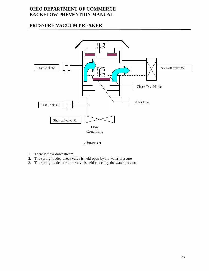
PRESSURE VACUUM BREAKER
Shut-off valve #2
Test Cock #1
Shut-off valve #1
Check Disk Holder
Check Disk
Flow
Conditions
Figure 18
1. There is flow downstream
2. The spring-loaded check valve is held open by the water pressure
3. The spring-loaded air-inlet valve is held closed by the water pressure
Test Cock #2
34
OHIO DEPARTMENT OF COMMERCE
BACKFLOW PREVENTION MANUAL
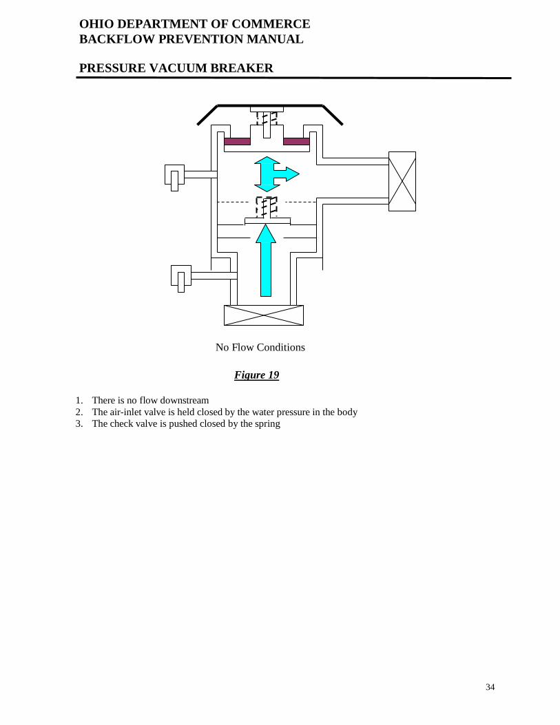
PRESSURE VACUUM BREAKER
No Flow Conditions
Figure 19
1. There is no flow downstream
2. The air-inlet valve is held closed by the water pressure in the body
3. The check valve is pushed closed by the spring
35
OHIO DEPARTMENT OF COMMERCE
BACKFLOW PREVENTION MANUAL
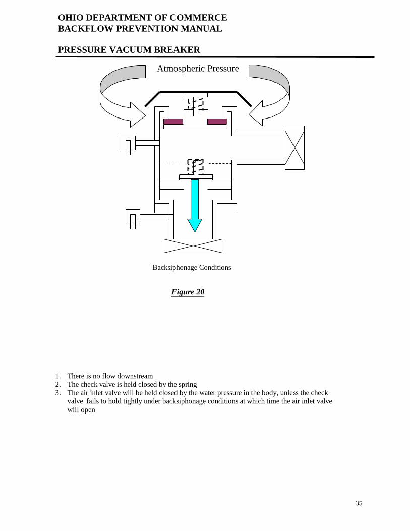
PRESSURE VACUUM BREAKER
Backsiphonage Conditions
Figure 20
1. There is no flow downstream
2. The check valve is held closed by the spring 3. The air inlet valve will be held closed by the water pressure in the body, unless the check
valve fails to hold tightly under backsiphonage conditions at which time the air inlet valve
will open
Atmospheric Pressure

36
OHIO DEPARTMENT OF COMMERCE
BACKFLOW PREVENTION MANUAL
INSTALLATION REQUIREMENTS CONTAINMENT DEVICES
It is your responsibility as the installer to be familiar with the local codes or regulations
regarding the proper installation of a containment backflow prevention device. It is
recommended that you consult with the water supplier before installing a containment
device.
The installation requirements for a containment principle backflow prevention device are
normally determined by the local water supplier. The following are a few of the typical
requirements.
- a containment device must be approved by the water supplier before installation,
most water suppliers accept the devices that meet ASSE, USC, CSA or AWWA
standards
- must be installed in a horizontal position
- must be 12” to 36” off of the floor
- test cocks must be facing into the room if they are side-mounted on the device
- must be installed in an area free of noxious fumes (for tester safety)
- must be accessible for inspection, testing and maintenance - an ASSE 1013 or 1047 may not be installed in a pit (due to the possibility of
flooding of the pit)
- you may not make a direct connection to the relief valve on an ASSE 1013 or ASSE 1047
- as ASSE 1015 or 1048 may be installed in a pit if approved by the local water supplier - you may not install an unprotected bypass around any backflow prevention device
(there must be equal protection on the bypass line) A bypass line may also be called
a manifold, parallel, dual or tandem setting.
The installation requirements for an isolation principle backflow prevention device are
normally determined by the Ohio plumbing code and the local plumbing inspection authorities.
Since there are few rules regarding the installation of isolation principle devices and if there
are no requirements by the local Plumbing Authorities, the Plumbing Unit of the Ohio
Department of Commerce suggests that you install an isolation device in accordance with the
manufacturer’s recommendations.
It is in your best interest to be familiar with the installation requirements because you can
eliminate unnecessary return trips to correct an improper installation.
If you are unsure of the local requirements, then you should contact the water supplier or
plumbing inspection authority for direction before you install the device.

37
OHIO DEPARTMENT OF COMMERCE
BACKFLOW PREVENTION MANUAL
BACKFLOW PREVENTER APPLICATION
ASSEMBLIES INSTALLED AS CONTAINMENT PROTECTION
The Ohio EPA recognizes only four types of backflow prevention assemblies for use as a
containment principle protection, the double check valve assembly, the reduced pressure
principle backflow preventer, the double check detector check assembly and the reduced
pressure detector check assembly.
Additionally, the Ohio EPA recognizes a properly installed pressure vacuum breaker as
acceptable backflow prevention protection for a residential irrigation system that has no pumps or
additives.
DEVICES INSTALLED AS ISOLATION PROTECTION
The Ohio Department of Commerce, Industrial Compliance Division recognizes those backflow
prevention devices that have obtained the American Society of Sanitary Engineering (ASSE)
seal authorization approval for use as an isolation principle backflow prevention protection.
The ASSE Standard Number will be stamped into the body of the device or printed on a metal
plate that is attached to the device.
The ASSE seal authorization approval list may be viewed at www.asse-plumbing.org.
In order to select the appropriate backflow prevention device for an application, it is necessary
that you understand the appropriate application and the limitations of the various devices.
The following informational charts indicate the available devices and their application.

38
OHIO DEPARTMENT OF COMMERCE
BACKFLOW PREVENTION MANUAL
BACKFLOW PREVENTION DEVICES
Pipe Applied Atmospheric Vacuum Breaker
Standard Number: ASSE 1001
Protection Provided: Backsiphonage Only
Hazard Level: High or Low Hazard
Limitation: May not be used under continuous pressure conditions
Must be installed at least 6” above the highest downstream use
May not have a downstream shut-off valve
Construction: A combination check valve / air inlet valve
Anti-Siphon Fill Valve (Ballcock) for Water Closet Flush Tank
Standard Number: ASSE 1002
Protection Provided: Backsiphonage Only
Hazard Level: High or Low Hazard
Limitation:
Construction: Float operated anti-siphon toilet ballcock
39
OHIO DEPARTMENT OF COMMERCE
BACKFLOW PREVENTION MANUAL
BACKFLOW PREVENTION DEVICES
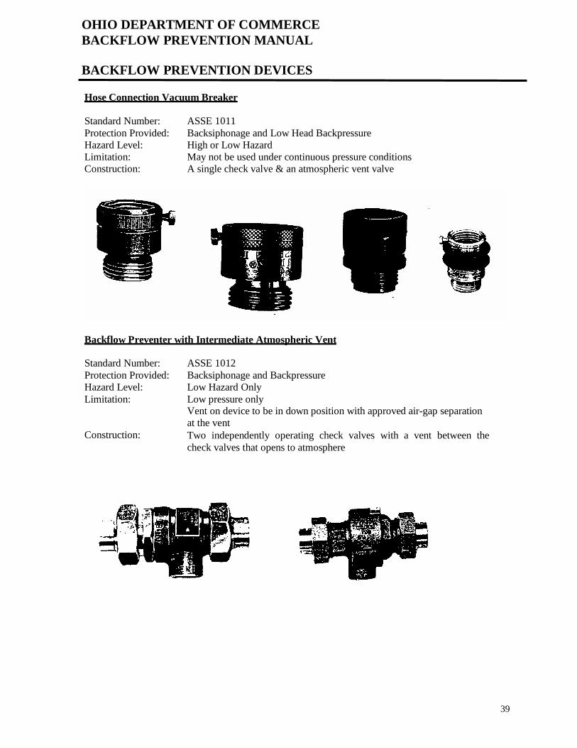
Hose Connection Vacuum Breaker
Standard Number: ASSE 1011
Protection Provided: Backsiphonage and Low Head Backpressure
Hazard Level: High or Low Hazard
Limitation: May not be used under continuous pressure conditions
Construction: A single check valve & an atmospheric vent valve
Backflow Preventer with Intermediate Atmospheric Vent
Standard Number: ASSE 1012
Protection Provided: Backsiphonage and Backpressure
Hazard Level: Low Hazard Only
Limitation: Low pressure only Vent on device to be in down position with approved air-gap separation
at the vent
Construction: Two independently operating check valves with a vent between the
check valves that opens to atmosphere

OHIO DEPARTMENT OF COMMERCE
BACKFLOW PREVENTION MANUAL
BACKFLOW PREVENTION DEVICES
40
Reduced Pressure Principle Backflow Preventer
Standard Number: ASSE 1013
Protection Provided: Backsiphonage and Backpressure
Hazard Level: High or Low Hazard
Limitation: May not be installed in a pit Must maintain an approved air-gap separation at the relief valve vent
port
Construction: Two independently-acting check valves, a hydraulic relief valve between
the check valves, tightly closing inlet & outlet valves, four appropriately
located test cocks
Reduced Pressure Principle Detector Check Assembly
Standard Number: ASSE 1047
Protection Provided: Backsiphonage and Backpressure
Hazard Level: High or Low Hazard
Limitation: Used for fire protection systems containing any additive or a connection
to stored water or an auxiliary water source
May not be installed in a pit Construction: Two reduced pressure assemblies installed in parallel, four test cocks on
each assembly, and a bypass meter to detect low water flow usage

OHIO DEPARTMENT OF COMMERCE
BACKFLOW PREVENTION MANUAL
BACKFLOW PREVENTION DEVICES
41
Double Check Backflow Prevention Assembly
Standard Number: ASSE 1015
Protection Provided: Backsiphonage and Backpressure
Hazard Level: Low Hazard Only
Limitation:
Construction: Two independently-acting check valves, tightly closing inlet & outlet
valves, and four appropriately located test cocks
Double Check Detector Check Assembly
Standard Number: ASSE 1048
Protection Provided: Backsiphonage and Backpressure
Hazard Level: Low Hazard Only
Limitation: Used for fire protection systems containing no additives, storage or
auxiliary water connection
Construction: Two double check valve assemblies installed in parallel, four test cocks
on each assembly, and a bypass meter to detect low water flow usage

OHIO DEPARTMENT OF COMMERCE
BACKFLOW PREVENTION MANUAL
BACKFLOW PREVENTION DEVICES
42
Vacuum Breaker Wall Hydrant, Freeze Resistant, Automatic Draining Type
Standard Number: ASSE 1019
Protection Provided: Backsiphonage and Low Head Backpressure
Hazard Level: High or Low Hazard
Limitation: May not be used under continuous pressure conditions
Construction: A wall hydrant with an internal vent valve and a means to drain the
barrel to prevent freezing
Pressure Vacuum Breaker Assembly
Standard Number: ASSE 1020
Protection Provided: Backsiphonage Only
Hazard Level: High or Low Hazard
Limitation: The critical installation level is 12” above the highest downstream use
Construction: A spring-loaded check valve and an independently-acting, spring-loaded
air inlet valve, and tightly closing inlet & outlet valves
OHIO DEPARTMENT OF COMMERCE
BACKFLOW PREVENTION MANUAL
BACKFLOW PREVENTION DEVICES
43
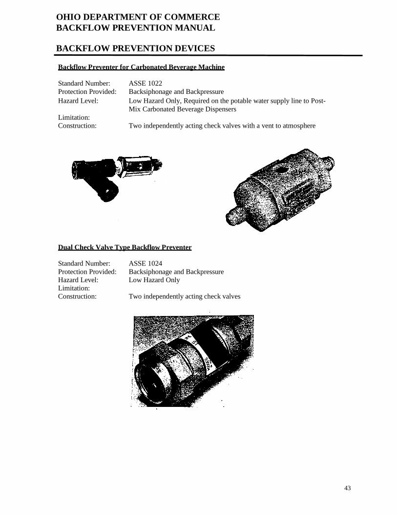
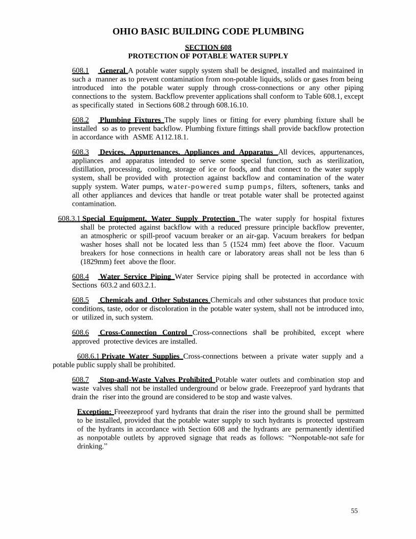
Backflow Preventer for Carbonated Beverage Machine
Standard Number: ASSE 1022
Protection Provided: Backsiphonage and Backpressure
Hazard Level: Low Hazard Only, Required on the potable water supply line to Post-
Mix Carbonated Beverage Dispensers
Limitation:
Construction: Two independently acting check valves with a vent to atmosphere
Dual Check Valve Type Backflow Preventer
Standard Number: ASSE 1024
Protection Provided: Backsiphonage and Backpressure
Hazard Level: Low Hazard Only
Limitation:
Construction: Two independently acting check valves

OHIO DEPARTMENT OF COMMERCE
BACKFLOW PREVENTION MANUAL
BACKFLOW PREVENTION DEVICES
44
Dual Check Valve Type Backflow Preventer for Post Mix Carbonated Beverage Dispensers
Standard Number: ASSE 1032
Protection Provided: Backsiphonage and Backpressure
Hazard Level: Low Hazard Only
Limitation:
Construction: Two independently acting check valves, usually found inside the
dispenser
Laboratory Faucet Backflow Preventer, Vacuum Breaker
Standard Number: ASSE 1035
Protection Provided: Backsiphonage and Low Head Backpressure
Hazard Level: High or Low Hazard
Limitation: May not be used under continuous pressure conditions
Construction: Two independently acting check valves with a means to vent to
atmosphere under backsiphonage conditions

OHIO DEPARTMENT OF COMMERCE
BACKFLOW PREVENTION MANUAL
BACKFLOW PREVENTION DEVICES
45
Hose Connection Backflow Preventer, Vacuum Breaker
Standard Number: ASSE 1052
Protection Provided: Backsiphonage and Low Head Backpressure
Hazard Level: High or Low Hazard
Limitation: May not be used under continuous pressure conditions
Construction: Two independently acting check valves with an intermediate vent to the
atmosphere
Backsiphonage Vacuum Breaker, Spill-Proof
Standard Number: ASSE 1056
Protection Provided: Backsiphonage Only
Hazard Level: High or Low Hazard
Limitation: The critical installation level is 6” above the highest downstream use or
1” when equipment mounted Construction: At least one check valve and an automatic vent valve to atmosphere,
tightly closing inlet & outlet valves, and a test cock

OHIO DEPARTMENT OF COMMERCE
BACKFLOW PREVENTION MANUAL
BACKFLOW PREVENTION DEVICES
46
Air-Gap Separation
Standard Number: ANSI A112.1.2
Protection Provided: Backsiphonage and Backpressure
Hazard Level: High or Low Hazard
Limitation: Must be at least two times the nominal diameter of the discharge piping
but never less than one inch Construction: A physical separation through the free atmosphere measured from the
opening of the discharge piping to the flood level rim of the receiving
vessel

BACKFLOW PREVENTION APPLICATION CHART
47
DEVICE ASSE NO. HAZARD LEVEL PROTECTION PROVIDED
Air Gap Separation ANSI
A112.1
Severe High, High or
Low Hazard
Backsiphonage / Backpressure
Pipe Applied Atmospheric
Type Vacuum Breaker
ASSE 1001
¼”- 4”
High or Low Hazard Backsiphonage Only
No continuous pressure
Anti-siphon Fill Valve
(Ballcock) for Water Closet
Flush Tank
ASSE 1002 High or Low Hazard Backsiphonage Only
Hose Connection Vacuum
Breaker
ASSE 1011 ½”, ¾”, 1”
High or Low Hazard Backsiphonage Low Head Backpressure
No continuous pressure
Backflow Preventer with
Intermediate Atmospheric
Vent
ASSE 1012
¼”- ¾”
Low Hazard
Low Pressure
Backsiphonage / Backpressure
Reduced Pressure Principle
Backflow Preventer
ASSE 1013
3/8” – 10”
High or Low Hazard Backsiphonage / Backpressure
Reduced Pressure Principle
Detector Check Assembly
ASSE 1047
1 ½” – 10”
High or Low Hazard
fire sprinkler systems
Backsiphonage / Backpressure
Double Check Backflow
Prevention Assembly
ASSE 1015 3/8” – 10”
Low Hazard Only Backsiphonage / Backpressure
Double Check Detector
Check Assembly
ASSE 1048 1 ½” – 10”
Low Hazard Only
fire sprinkler systems
Backsiphonage / Backpressure
Vacuum Breaker Wall
Hydrant, Freeze-Resistant,
Automatic Draining Type
ASSE 1019
¾” & 1”
High or Low Hazard Backsiphonage Low Head Backpressure
No continuous pressure
Pressure Vacuum Breaker
Assembly
ASSE 1020 ½” – 2”
High or Low Hazard Backsiphonage Only
Backflow Preventer for
Carbonated Beverage
Machine
ASSE 1022 ¼” – 3/8”
Low Hazard Only Backsiphonage / Backpressure
Dual Check Valve Type
Backflow Preventer
ASSE 1024
Sizes ¼”- 1”
Low Hazard Only Backsiphonage / Backpressure
Dual Check Valve Type
Backflow Preventer for Post-
Mix Beverage Dispenser
ASSE 1032
¼” – 3/8”
Low Hazard Only Backsiphonage / Backpressure
Laboratory Faucet Backflow
Preventer, Vacuum Breaker
ASSE 1035
3/8”
High or Low Hazard Backsiphonage
Low Head Backpressure
No continuous pressure
Hose Connection Backflow
Preventer, Vacuum Breaker
ASSE 1052
½” – 1”
High or Low Hazard Backsiphonage
Low Head Backpressure
Backsiphonage Vacuum
Breaker, Spill-Proof
ASSE 1056 1/8” – 2”
High or Low Hazard Backsiphonage Only

BACKFLOW PREVENTION APPLICATION CHART
48
INSTALLATION EXAMPLES OF INSTALLATION
Should be used whenever possible, is the only
absolute means of preventing backflow
Lavatories, process tanks, sinks, bathtubs, and
cooling towers
May not have a downstream valve since this
device is not designed to operate under
continuous pressure
Irrigation systems, process tanks, dishwashers,
and soap dispensers
Tank type water closet or flush tank for
urinals
Gravity fill water closet or flush tank type
urinals
Low head backpressure is intended to mean
negligible backpressure in the 1.0 psi to 2.0
psi range, no continuous pressure over 12 hrs
Hose bib connections
Low hazard cross-connections under
continuous pressure, but may not be subject to
high-pressure backpressure
Low-pressure boilers or cooling towers
containing no additives
Cross-connections subject to backsiphonage
or backpressure and operating under
continuous pressure
Main supply lines, commercial or chemically
treated boilers or chillers, main hospital lines
and equipment, tanks with submerged inlets
Installed on a fire protection system
containing any additive, even a food-grade
additive
Chemically charged fire protection systems
(such as Foamite), or a fire protection system
that contains any additive or anti-freeze
Installed to prevent the backflow of a
substance that would not present a hazard to
health
Main supply lines, food cookers, tanks or vats
containing non-toxic substances
Installed on a fire protection system that
contains only the public water, has no booster
pump, storage, or auxiliary water
Non-chemically charged and/or non-toxic fire
protection systems; a fire sprinkler system that
is filled with water from the public water supply
Low head backpressure is intended to mean
negligible backpressure in the 1.0 psi to 2.0
psi range, no continuous pressure over 12 hrs.
Wall hydrant hose bib
Continuous pressure is OK because the air-
inlet and check valve are spring-loaded
Irrigation systems, plating tanks, livestock
watering systems, supply to a submerged inlet
Constructed of non-copper material, must
include a strainer Installed on the water supply line to carbonated
beverage dispensers prior to the carbonating
point, no copper beyond this device
Low hazard cross-connections, continuous
pressure, backsiphonage and backpressure
Residential water service connections,
individual outlets
Independently-acting check valves Installed inside the post-mix type carbonated
beverage dispensers, by the beverage
maintenance personnel
Low head backpressure is intended to mean
negligible backpressure in the 1.0 psi to 2.0
psi range, no continuous pressure over 12 hrs
Laboratory faucets
Low head backpressure is intended to mean
negligible backpressure in the 1.0 psi to 2.0
psi range, no continuous pressure over 12 hrs
Hose bib connections
Used in areas where water spillage may
present a problem
X-ray or photo developing machines

49
OHIO DEPARTMENT OF COMMERCE
BACKFLOW PREVENTION MANUAL
APPLICATION CHART
You will have to understand and memorize the information on the backflow prevention
application chart to properly utilize the protection provided by the various types of devices.
Assume that all backflow prevention devices
operate under the these conditions
Backpressure Backsiphonage
High Hazard Low Hazard
Any backflow prevention device with the word
dual or double in its name is not acceptable as
protection against a high hazard
Backpressure Backsiphonage
Low Hazard
Any backflow prevention device with the word
vacuum in its name is not acceptable as
protection against backpressure
Backsiphonage
High Hazard Low Hazard
Atmospheric Pressure
You can remember the appropriate critical
installation level for a vacuum breaker by using
this chart. “A” comes before “P” alphabetically
and “6” comes before “12” numerically.
1001 1020
6” 12”
Keep in mind that some terms are used
interchangeably and imply the same condition.
Pollution = Low Hazard = Non-Toxic
Contaminant = High Hazard = Toxic

OHIO DEPARTMENT OF COMMERCE
BACKFLOW PREVENTION MANUAL
THERMAL EXPANSION CONTROL
50
The Ohio Basic Building Code, Plumbing; Section 607, “Hot Water Supply System”, Sub-
Section 607.3.2, “Backflow Prevention Device or Check Valve” specifies that:
“Where a backflow prevention device, check valve, or other device is installed on a water
supply system utilizing storage water heating equipment such that thermal expansion causes
an increase in pressure, a device for controlling pressure shall be installed.”
Thermal expansion of heated water will occur wherever potable water is heated in a closed
system. Uncontrolled thermal expansion usually results in leaking faucets or burst washing
machine supply hoses, but may result in the collapse of the vent pipe on gas-fired water
heaters, or violently burst water heaters in extreme cases.
An expansion tank is one method (others methods are available refer to plumbing code)
designed to absorb thermal expansion that will be created by the hot water heater, if the
water user’s potable system is closed with a containment principle backflow prevention
assembly, a check valve or a pressure reducing valve without an internal bypass.
The expansion tank must be installed in the cold water service piping on the supply side of the
hot water heater prior to any control valves. The size of the expansion tank is based upon
the size of the hot water heater and may be determined by referring to the manufacturer
recommendations.
Figure 21
Cold water supply Hot water to
building
T & P valve
Water
pressure
Pressurized air
below rubber
diaphragm

51
OHIO DEPARTMENT OF COMMERCE
BACKFLOW PREVENTION MANUAL
BAROMETRIC LOOP
A barometric loop is a backflow prevention method that may be used as a protection only
against backsiphonage. The critical installation level of a barometric loop is 35’ above the
flood level rim of the highest downstream fixture being supplied. Since atmospheric pressure
will elevate water to a height of only 34 feet (14.7 psig X 2.31), then the 35’ loop
prevents a backsiphonage from occurring.
A barometric loop is not effective against backpressure but is effective against a low or high
hazard and is usually installed on a single process line within the consumer’s distribution
system.

52
OHIO DEPARTMENT OF COMMERCE
BACKFLOW PREVENTION MANUAL
AUXILIARY WATER SOURCES
An auxiliary water system is any water system on or available to the premises other than the
public water system. These auxiliary water systems shall include used water or water from a
source other than the public water system, such as wells, cisterns or open reservoirs that
are equipped with pumps or other prime movers, including gravity.
An auxiliary water source may only be interconnected with the consumer’s piping
provided it meets the Ohio EPA requirements and is approved by the water supplier and
the Ohio Environmental Protection Agency.
An interchangeable connector is the only approved means to interconnect a consumer’s
auxiliary water source with the piping connected to the public water system. The
consumer’s water piping and an auxiliary water source may be interconnected only in an
industrial setting and provided it is approved by the Ohio EPA (this is the exception to the
general rule that the Ohio EPA has no authority inside the building).
If the use of an interchangeable connector is approved, then an approved containment
principle reduced pressure backflow preventer must be installed at the water meter and on the
leg prior to the interchangeable connector that is supplying water from the consumer’s water
distribution system. See page 53 for drawings on installation requirements.
In a residential setting the public water service shall not be interconnected with an auxiliary
water source under any condition.
It must be noted that any premises that has an auxiliary water source on or available to the
premises must have a containment reduced pressure principle backflow prevention assembly
installed at the water meter even though there is no intent to interconnect the two sources. This
requirement is due to the potential for the two sources to be inadvertently interconnected in the
future.

53
OHIO DEPARTMENT OF COMMERCE
BACKFLOW PREVENTION MANUAL
INTERCHANGEABLE CONNECTOR
There are two types of interchangeable connectors.
Supply from City
RP Assembly
Swing connector rotates 180 degrees to supply water from auxiliary source
To downstream demand
Supply from Auxiliary
Swi ng Connector
= control valve
To downstream demand
Supply from City Supply from Auxiliary
RP Assembly
Internal channels rotate 90 degrees
If supplied from city water
If supplied from auxiliary water
Four-Way Valve
The drain port on the four way valve shall not be installed in the vertical position
Diagrams from the Ohio EPA Manual

54
OHIO DEPARTMENT OF COMMERCE
BACKFLOW PREVENTION MANUAL
LOW-SUCTION PRESSURE CUT-OFF CONTROLLER
The Ohio Environmental Protection Agency and the Ohio Department of Commerce require
that a low-suction pressure cut-off controller must be installed on any domestic water booster
pump that takes direct suction from the public water system. This applies to potable water
pumps not intended for fire suppression.
A low-suction pressure cut-off controller (LPS) is intended to shut-off a booster pump, if
the pressure on the suction-side of that booster pump drops to 10 psig. There is a thirty
second delay after the pressure drops to 10 psig, and the LPS will shut-down the booster pump
if the suction-side pressure remains at 10 psig for that entire thirty second period.
It is an electronic controller that senses the supply pressure to the booster pump via a
piped connection at the suction-side of the booster pump. It is wired to the booster pump
controller. If the pressure on the suction-side of the pump drops to 10 psig, there is a
prescribed set of audible and visual indicators on the LPS controller indicating that a low-
suction pressure condition exists.
Most booster pump manufacturers now include the low-suction cut-off controller as an integral part of
the pump controller. The stand alone cut-off controller as shown in the illustration will be necessary
only on a retrofit of an existing booster pump. These controllers must be tested at the time of installation
and every twelve months thereafter.
Illustration from Ohio EPA Manual
55
OHIO BASIC BUILDING CODE PLUMBING
SECTION 608
PROTECTION OF POTABLE WATER SUPPLY
608.1 General A potable water supply system shall be designed, installed and maintained in
such a manner as to prevent contamination from non-potable liquids, solids or gases from being
introduced into the potable water supply through cross-connections or any other piping
connections to the system. Backflow preventer applications shall conform to Table 608.1, except
as specifically stated in Sections 608.2 through 608.16.10.
608.2 Plumbing Fixtures The supply lines or fitting for every plumbing fixture shall be
installed so as to prevent backflow. Plumbing fixture fittings shall provide backflow protection
in accordance with ASME A112.18.1.
608.3 Devices, Appurtenances, Appliances and Apparatus All devices, appurtenances,
appliances and apparatus intended to serve some special function, such as sterilization,
distillation, processing, cooling, storage of ice or foods, and that connect to the water supply
system, shall be provided with protection against backflow and contamination of the water
supply system. Water pumps, water -powered sump pumps, filters, softeners, tanks and
all other appliances and devices that handle or treat potable water shall be protected against
contamination.
608.3.1 Special Equipment, Water Supply Protection The water supply for hospital fixtures
shall be protected against backflow with a reduced pressure principle backflow preventer,
an atmospheric or spill-proof vacuum breaker or an air-gap. Vacuum breakers for bedpan
washer hoses shall not be located less than 5 (1524 mm) feet above the floor. Vacuum
breakers for hose connections in health care or laboratory areas shall not be less than 6
(1829mm) feet above the floor.
608.4 Water Service Piping Water Service piping shall be protected in accordance with
Sections 603.2 and 603.2.1.
608.5 Chemicals and Other Substances Chemicals and other substances that produce toxic
conditions, taste, odor or discoloration in the potable water system, shall not be introduced into,
or utilized in, such system.
608.6 Cross-Connection Control Cross-connections shall be prohibited, except where
approved protective devices are installed.
608.6.1 Private Water Supplies Cross-connections between a private water supply and a
potable public supply shall be prohibited.
608.7 Stop-and-Waste Valves Prohibited Potable water outlets and combination stop and
waste valves shall not be installed underground or below grade. Freezeproof yard hydrants that
drain the riser into the ground are considered to be stop and waste valves.
Exception: Freeezeproof yard hydrants that drain the riser into the ground shall be permitted
to be installed, provided that the potable water supply to such hydrants is protected upstream
of the hydrants in accordance with Section 608 and the hydrants are permanently identified
as nonpotable outlets by approved signage that reads as follows: “Nonpotable-not safe for
drinking.”

56
608.8 Identification of Potable and Non-Potable Water In buildings where nonpotable water
systems are installed, the piping conveying the nonpotable water shall be identified by either color
marking or metal tags in accordance with Section 608.8.1 through 608.8.3. All nonpotable water
outlets such as hose connections, open ended pipes, and faucets shall be identified at the point of
use for each outlet with the words, “Nonpotable-not safe for drinking.” The words shall be indelibly
printed on a tag or sign constructed of corrosion resistant waterproof material or shall be indelibly
printed on the fixture. The letters of the words shall not be less than0.5 inches in height and color
in contrast to the background on which they are applied.
608.8.1 Information Pipe identification shall include the contents of the piping system and
an arrow indicating the direction of flow. Hazardous piping systems shall also contain
information addressing the nature of the hazard. Pipe identification shall be repeated at
maximum intervals of 25 feet (7620 mm) and at each point where the piping passes
through a wall, floor or roof. Lettering shall be readily observable within the room or space
the piping is located.
608.8.2 Color The color of the pipe identification shall be discernible and consistent
throughout the building. The color purple shall be used to identify reclaimed, rain and gray
water distribution systems.
608.8.3 Size The size of the background color field and lettering shall comply with Table
608.8.3
TABLE 608.8.3
SIZE OF PIPE IDENTIFICATION
PIPE DIAMETER
(inches)
LENGTH OF BACKGROUND COLOR
FIELD (inches)
SIZE OF LETTERS
(inches)
¾ to 1-1/4 8 0.5
1-1/2 to 2 8 0.75
2-1/2 to 6 12 1.25
8 to 10 24 2.5
Over 10 32 3.5 For SI: 1inch = 25.4 mm
608.9 Reutilization Prohibited Water utilized for the cooling of equipment or other processes
shall not be returned to the potable water system. Such water shall be discharged into a drainage
system through an air-gap or shall be utilized for non-potable purposes.
608.10 Reuse of Piping Piping that has been used for any purpose other than conveying potable
water shall not be utilized for conveying potable water.
608.11 Painting of Water Tanks The interior surface of a potable water tank shall not be lined,
painted or repaired with any material that changes the taste, odor, color or potability of the water
supply when the tank is placed in, or returned to, service.
608.12 Pumps and other appliances Water pumps, water powered sump pumps, filters, softeners,
tanks and all other devices that handle or treat potable water shall be protected against
contamination.
608.13 Backflow Protection Means of protection against backflow shall be provided in
accordance with Sections 608.13.1 through 608.13.9.
608.13.1 Air-Gap Separation The minimum required air-gap shall be measured vertically
from the lowest end of a potable water outlet to the flood level rim of the fixture or

57
receptacle into which such potable water outlet discharges. Air gaps shall comply with
ASME A112.1.2 and the air gap fitting shall comply with ASME A112.1.3.
608.13.2 Reduced Pressure Principle Backflow Preventer Reduced pressure principle
backflow preventers shall conform to ASSE 1013, AWWA C511, CSA B64.4 or CSA
B64.4.1. Reduced pressure detector assembly backflow preventers shall conform to ASSE
1047. These devices shall be permitted to be installed where subject to continuous pressure.
The relief opening shall discharge by air gap and shall be prevented from being submerged.
608.13.3 Backflow Preventer with Intermediate Atmospheric Vent Backflow Preventers
with intermediate atmospheric vents shall conform to ASSE 1012 or CSA B64.3. These
devices shall be permitted to be installed where subject to continuous pressure conditions. The
relief opening shall discharge by air gap and shall be prevented from being submerged.
608.13.4 Barometric Loop Barometric loops shall precede the point of connection and
shall extend vertically to a height of 35 feet (10,688 mm). A barometric loop shall only be
utilized as an atmospheric-type or pressure-type vacuum breaker.
608.13.5 Pressure-Type Vacuum Breakers Pressure-type vacuum breakers shall conform to
ASSE 1020 or CSA B64.1.2 and spill-proof vacuum breakers shall comply with ASSE 1056.
These devices are designed for installation under continuous pressure conditions when the
critical installation level is installed at the required height. Pressure type vacuum breakers
shall not be installed in locations where spillage could cause damage to the structure.
608.13.6 Atmospheric-Type Vacuum Breakers Pipe-applied atmospheric-type vacuum
breakers shall conform to ASSE 1001 or CSA B64.1.1. Hose connection vacuum breakers
shall conform to ASSE 1011, ASSE 1019, ASSE 1035, ASSE 1052, CSA B64.2, CSA
B64.2.1, CSA B64.2.1, CSA B64.2.1.1, CSA B64.2.2 or CSA B64.7. These devices shall
operate under normal atmospheric pressure when the critical installation level is installed at the
required height.
608.13.7 Double Check Valve Assemblies Double check valve assemblies shall conform to
ASSE 1015, CSA B64.5, CSA B64.5.1 or AWWA C510. Double detector check valve
assemblies shall conform to ASSE 1048. These devices shall be capable of operating under
continuous pressure.
608.13.8 Spill Proof Vacuum Breakers Spill proof vacuum breakers (SVB) shall conform to
ASSE 1056. These devices are designed for installation under continuous pressure
conditions when the critical installation level is installed at the required height.
608.13.9 Chemical Dispenser Backflow Devices Backflow devices for chemical dispensers
shall comply with ASSE 1055 or shall be equipped with an air gap fitting.
608.14 Location of Backflow Preventers Access shall be provided to backflow preventers as
specified by the installation instructions of the approved manufacturer.
608.14.1 Outdoor enclosures for backflow prevention devices Outdoor enclosures
for backflow prevention devices shall comply with ASSE 1060.
608.14.2 Protection of backflow preventers Backflow preventers shall not be located
in areas subject to freezing except where they can be removed by means of unions
or are protected from freezing by heat, insulation or both.
608.14.2.1 Relief port piping The termination of the piping from the relief port or air gap fitting of a
backflow preventer shall discharge to an approved indirect waste receptor or to the outdoors
where it will not cause damage or create a nuisance.

58
608.15 Protection of Potable Water Outlets All potable water openings and outlets shall be
protected against backflow in accordance with Section 608.15.1, 608.15.2, 608.15.3, 608.15.4,
608.15.4.1, 608.15.4.2.
608.15.1 Protection by an air gap Openings and outlets shall be protected by an air
gap between the opening and the fixture flood level rim as specified in Table 608.15.1.
Openings and outlets equipped for hose connection shall be protected by means other
than an air gap.
608.15.2 Protection by a reduced pressure principle backflow preventer Openings
and outlets shall be protected by a reduced pressure principle backflow preventer.
608.15.3 Protection by a backflow preventer with intermediate atmospheric vent
Openings and outlets shall be protected by a backflow preventer with an intermediate atmospheric vent.
608.15.4 Protection by a Vacuum Breaker Openings and outlets shall be protected
by atmospheric-type or pressure-type vacuum breakers. The critical level of the vacuum
breaker shall be set a minimum of 6 inches (152 mm) above the flood level rim of
the fixture or device. Fill valve shall be set in accordance with Section 425.3.1.
Vacuum Breakers shall not be installed under exhaust hoods or similar locations that
will contain toxic fumes or vapors. Pipe-applied vacuum breakers shall be installed
not less than 6 inches (152 mm) above the flood level rim of the fixture, receptor or
device served.
TABLE 608.15.1
MINIMUM REQUIRED AIR GAPS
MINIMUM AIR GAP
FIXTURE
AWAY
FROM A
WALL (inches)
CLOSE TO
A WALL
(inches)
Lavatories and other fixtures with effective opening not greater than 1/2
inch in diameter
1 1.5
Sink, laundry trays, gooseneck back faucets and other fixtures with
effective openings not greater than 3/4 inch in diameter
1.5
2.5
Over-rim bath fillers and other fixtures with effective openings not greater
than 1 inch in diameter
2
3
Drinking water fountains, single orifice not greater than 7/16 inch in
diameter or multiple orifices with a total area of 0.150 square inch (area of
circle 7/16 inch in diameter)
1
1.5
Effective openings greater than 1 inch Two times the
diameter of the
effective
opening
Three times
the diameter
of the
effective
opening
For SI: 1inch = 25.4 mm a. Applicable where walls or obstructions are spaced from the nearest inside-edge of the spout opening a
distance greater than three times the diameter of the effective opening for a single wall, or a distance greater
than four times the diameter of the effective opening for two intersecting walls.
608.15.4.1 Deck Mounted and Integral Vacuum Breakers Approved deck
mounted or equipment mounted vacuum breakers and faucets with integral
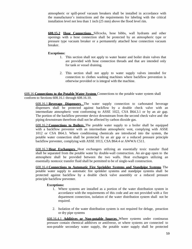
59
atmospheric or spill-proof vacuum breakers shall be installed in accordance with
the manufacturer’s instructions and the requirements for labeling with the critical
installation level not less than 1 inch (25 mm) above the flood level rim.
608.15.2 Hose Connections Sillcocks, hose bibbs, wall hydrants and other
openings with a hose connection shall be protected by an atmospheric type or
pressure type vacuum breaker or a permanently attached hose connection vacuum
breaker.
Exceptions: 1. This section shall not apply to water heater and boiler drain valves that
are provided with hose connection threads and that are intended only
for tank or vessel draining.
2. This section shall not apply to water supply valves intended for
connection to clothes washing machines where backflow prevention is
otherwise provided or is integral with the machine.
608.16 Connections to the Potable Water System Connections to the potable water system shall
conform to Sections 608.16.1 through 608.16.10.
608.16.1 Beverage Dispensers The water supply connection to carbonated beverage
dispensers shall be protected against backflow by a double check valve with an
intermediate atmospheric vent conforming to ASSE 1022, CSA B64.3.1 or by an air gap.
The portion of the backflow preventer device downstream from the second check valve and the
piping downstream therefrom shall not be affected by carbon dioxide gas.
608.16.2 Connections to Boilers The potable water supply to a boiler shall be equipped
with a backflow preventer with an intermediate atmospheric vent, complying with ASSE
1012 or CSA B64.3. Where conditioning chemicals are introduced into the system, the
potable water connection shall be protected by an air gap or a reduced pressure principle
backflow preventer, complying with ASSE 1013, CSA B64.4 or AWWA C511.
608.16.3 Heat Exchangers Heat exchangers utilizing an essentially toxic transfer fluid
shall be separated from the potable water by double-wall construction. An air-gap open to the
atmosphere shall be provided between the two walls. Heat exchangers utilizing an
essentially nontoxic transfer fluid shall be permitted to be of single-wall construction.
608.16.4 Connections to Automatic Fire Sprinkler Systems and Standpipe Systems The potable water supply to automatic fire sprinkler systems and standpipe systems shall be
protected against backflow by a double check valve assembly or a reduced pressure principle backflow preventer.
Exceptions: 1. Where systems are installed as a portion of the water distribution system in
accordance with the requirements of this code and are not provided with a fire
department connection, isolation of the water distribution system shall not be
required.
2. Isolation of the water distribution system is not required for deluge, preaction
or dry pipe systems
608.16.4.1 Additives or Non-potable Sources Where systems under continuous
pressure contain chemical additives or antifreeze, or where systems are connected to
non-potable secondary water supply, the potable water supply shall be protected

60
against backflow by a reduced pressure principle backflow preventer. Where chemical
additives or antifreeze are added to only a portion of an automatic fire sprinkler or
standpipe system, the reduced pressure principle backflow preventer shall be
permitted to be located so as to isolate that portion of the system. Where systems are
not under continuous pressure, the potable water supply shall be protected against
backflow by an air gap or a pipe applied atmospheric vacuum breaker conforming
to ASSE 1001 or CSA B64.1.1.
608.16.5 Connections to Lawn Irrigation Systems The potable water supply to lawn
irrigation systems shall be protected against backflow by an atmospheric type vacuum
breaker, a pressure type vacuum breaker or a reduced pressure principle backflow preventer.
A valve shall not be installed downstream from an atmospheric vacuum breaker. Where
chemicals are introduced into the system, the potable water supply shall be protected against
backflow by a reduced pressure principle backflow preventer.
608.16.6 Connections Subject to Backpressure Where a potable water connection is made
to a non-potable line, fixture, tank, vat, pump or other equipment subject to backpressure, the
potable water connection shall be protected by a reduced pressure principle backflow preventer.
608.16.7 Chemical Dispensers Where chemical dispensers connect to the water
distribution system, the water supply system shall be protected against backflow in
accordance with Section 608.13.1, 608.13.2, 608.13.5, 608.13.6, 608.13.8 or 608.13.9.
608.16.8 Portable Cleaning Equipment Where the portable cleaning equipment connects to
the water distribution system, the water supply system shall be protected against backflow in
accordance with Section 608.13.1, 608.13.2, 608.13.3, 608.13.7 or 608.13.8.
608.16.9 Dental Pump Equipment Where dental pumping equipment connects to the
water distribution system, the water supply system shall be protected against backflow in
accordance with Section 608.13.1, 608.13.2, 608.13.5, 608.13.6 or 608.13.8.
608.16.10 Coffee machines and noncarbonated beverage dispensers The water supply
connection to coffee machines and noncarbonated beverage dispensers shall be protected by a
backflow preventer conforming to ASSE 1022 or by an air gap.
608.17 Protection of individual water supplies An individual water supply, otherwise
known as a private water system, shall be located and constructed so as to be safeguarded
against contamination in accordance with the rules of the “Ohio Department of Health”
contained within Chapter 3701-28 of the Administrative Code, “Private Water systems.”
61
APPLICATION OF PROPER BACKFLOW PROTECTION
FOR THESE SPECIFIC PLUMBING COMPONENTS
WATER POWERED BACKUP SUMP PUMPS
This cross connection shall be considered a high hazard connection and shall be
protected by a backflow device or method that would provide high hazard protection
against backsiphonage by the proper installation of a device providing such
protection. These devices shall be one of the following Air gap, Reduced pressure
principle backflow preventer, Pressure-type vacuum breaker, Atmospheric-type
vacuum breaker, Spillproof vacuum breaker. For additional information refer to
the Ohio Plumbing Code sections 608.13.1, 608.13.2, 608.13.5, 608.13.6 or
608.13.8. The Water purveyor may require containment protection at the service
entrance.
POST TYPE BURY LAWN HYDRANTS
This cross connection shall be considered a high hazard connection and shall be
protected by a backflow device or method that would provide high hazard protection
against backsiphonage by the proper installation of a reduced pressure principle
backflow preventer on the supply side of the hydrant. For additional information
refer to the Ohio Plumbing Code section 608.13.2. The outlet at the hydrant shall be
labeled in an appropriate manner indicating that it is non potable/non drinking water.
The Water purveyor may require containment protection at the service entrance.
PIPING SYSTEMS CONTAINING ETHYLENE GLYCOL
These systems are prohibited to be directly connection to a public water system
and domestic water systems. They shall be provided with an approved air gap
separation.
WATER LUBRICATED/WATER SEAL SEWAGE PUMPS
These systems are prohibited to be direct connection to a public water system and
domestic water systems. They shall be provided with an approved air gap
separation. To supply water to these pumps from a public water system it shall be
through a secondary pump system that provides the water to a storage tank by air
gap from which the pump system draws its water for pressurization to these types of
pumps.

OHIO DEPARTMENT OF COMMERCE
BACKFLOW PREVENTION MANUAL
OHIO ADMINISTRATIVE CODE, OEPA
62
The following material is from the Ohio Administrative Code, and represents the
regulations adopted by the Ohio Environmental Protection Agency on October 9,
1980. They replace and are essentially the same as Regulation HE-34 that was
adopted by the Public Health Council of the Ohio Department of Health on April 15,
1972.
The local water supplier is responsible for and authorized to enforce these
regulations, pertaining to containment principle protection, in his/her water
distribution system.
The Ohio Environmental Protection Agency has published a Manual of Backflow
Prevention and Cross-Connection Control which contains this Administrative Code
and all of their rules, regulations, policies, guidelines and illustrations.
Chapter 3745-95-02; Cross-Connections
(A) No person shall install or maintain a water service connection to any premises where actual or potential cross-connections to a public water system or a
consumer’s water system may exist unless such actual or potential cross-
connections are abated or controlled to the satisfaction of the supplier of water.
(B) No person shall install or maintain any connection whereby water from an
auxiliary water system may enter a public water system or consumer’s water
system unless the auxiliary water system, the method of connection and use of
such system have been approved by the supplier of water and by the director as
required by Section 6109.13 of the Revised Code.
Chapter 3745-95-03; Surveys and Investigations
(A) The supplier of water shall conduct or cause to be conducted periodic surveys and investigations, of frequency acceptable to the director of water use practices
within a consumer’s premises to determine whether there are actual or
potential cross- connections to the consumer’s water system through which
pollutants or contaminants could backflow into the public water system.
(B) The supplier of water, or his authorized representative, shall have the right to
enter premises served by the public water system at all reasonable times for the
purpose of making surveys and investigations of water use practices within the
premises.

OHIO DEPARTMENT OF COMMERCE
BACKFLOW PREVENTION MANUAL
OHIO ADMINISTRATIVE CODE, OEPA
63
(C) On request by the supplier of water, or his authorized representative, the
consumer shall furnish the supplier of water, or his authorized representative,
information of water use practices within the consumer’s premises.
(D) Paragraph (A) of this rule does not relieve the consumer of the responsibility
for conducting, or causing to be conducted, periodic surveys of water use
practices on his premises to determine whether there are actual or potential
cross-connections in the consumer’s water system through which pollutants or
contaminants could backflow into a public water system or a potable consumer’s
water system.
Chapter 3745-95-04 Where Protection is Required
(A) An approved backflow prevention device shall be installed on each service line to a consumer’s water system serving premises, where in the judgement of the supplier of water or the director, a pollution, system, health or severe health hazard to the public water exists.
(B) An approved backflow prevention device shall be installed on each service line to a consumer’s water system serving premises where any of the following conditions exist:
(1) Premises having an auxiliary water system, unless such auxiliary system is accepted as an additional source by the supplier of water
and the source is approved by the director;
(2) Premises on which any substance is handled in such a fashion as to
create an actual or potential hazard to a public water system. This shall
include premises having sources or systems containing process fluids or
waters originating from a public water system which are no longer under
the control of the supplier of water;
(3) Premises having internal cross-connections that, in the judgment of the
supplier of water, are not correctable, or intricate plumbing arrangements
which make it impractical to determine whether or not cross-connections
exist;
(4) Premises where, because of security restrictions or other prohibitions or
restrictions, it is impossible or impractical to make a complete cross-
connection survey;
(5) Premises having a repeated history of cross-connections being established
or re- established;

OHIO DEPARTMENT OF COMMERCE
BACKFLOW PREVENTION MANUAL
OHIO ADMINISTRATIVE CODE, OEPA
64
(C) The following requirements apply to premises that have an auxiliary water
system on the real property that is owned or under control of the consumer and
adjacent to the premises”.
1) A physical separation shall be maintained between the public water system
or a consumers’ water system and the auxiliary water system as required
by paragraph (B) of rule 3745-95-02 of the Administrative Code: and
2) An approved backflow prevention device shall be installed on each
service connection serving the consumers’ water system, unless the
supplier of water does all of the following:
a. Determines, on a case-by-case basis, that the installation of an
approved backflow prevention device is not required in
consideration of factors including, but not limited to, the past
history of cross connections being established or re-established on
the premises, the ease or difficulty of connecting the auxiliary
water system with the public water system on the premises, the
presence or absence of contaminants on the property or other risk
factors;
b. Requires the consumer to sign an agreement which specifies the
penalties, including those set forth in rule 3745-95-08 of the
Administrative Code, for creating a connection between the public
water system and the auxiliary water system:
c. Conducts or causes to be conducted an inspection at least every
twelve months to certify that no connection or means of
connection has been created between the public water system and
the auxiliary water system;
d. Maintains an inventory of each consumers’ premises, where an
auxiliary water system is on or available to the premises, or on
the real property adjacent to the premises; and
e. Develops and implements an education program to inform all
consumers served by the public water system about the dangers of
cross connections and how to eliminate cross connections.

OHIO DEPARTMENT OF COMMERCE
BACKFLOW PREVENTION MANUAL
OHIO ADMINISTRATIVE CODE, OEPA
65
(D) An approved backflow prevention device shall be installed on each service line to a consumer’s water system serving, but not necessarily limited to, the
following types of facilities unless the director determines that no health,
pollutional, or system hazard to the public water system exists:
(1) Hospitals, mortuaries, clinics, nursing homes;
(2) Laboratories;
(3) Piers, docks, waterfront facilities;
(4) Sewage treatment plants, sewage pumping stations, or storm water
pumping stations;
(5) Food or beverage processing plants;
(6) Chemical plants;
(7) Metal plating industries; (8) Petroleum processing or storage plants;
(9) Radioactive material processing plants or nuclear reactors;
(10) Car washes; and
(11) Others specified by the director.
(E) An approved backflow prevention device shall be installed at any point of
connection between a public water system or a potable consumer’s water system
and an auxiliary water system, unless such auxiliary system is acceptable as an
additional source by the supplier of water and the source is approved by the
director.
Chapter 3745-95-05 Type of Protection Required
(A) The type of protection required under paragraph (A), (B), (C) and (D) of Rule 3745- 95-04 of the Ohio Administrative Code shall depend on the degree of hazard which exists as follows:
(1) An approved air-gap separation shall be installed where a public water system can be contaminated with substances that could cause a severe
health hazard;
(2) An approved air-gap separation, or an approved reduced pressure
assembly, or an approved reduced pressure detector assembly shall be
installed where a public water system may be contaminated with
substances that could cause a health or system hazard;
(3) An approved air-gap separation, or an approved reduced pressure
assembly, or an approved reduced pressure detector assembly, or an
approved double check valve assembly, or an approved double check
detector assembly shall be installed where a public water system may
be polluted with substances that could cause a pollution hazard.

OHIO DEPARTMENT OF COMMERCE
BACKFLOW PREVENTION MANUAL
OHIO ADMINISTRATIVE CODE, OEPA
66
(B) The type of protection required under paragraph (E) of Rule 3745-95-04 of the
Ohio Administrative Code shall be an approved air-gap separation or an
approved interchangeable connection.
(C) Where an auxiliary water system is used as a secondary source of water for a
fire protection system, the provisions of paragraph (B) of this Rule for an
approved air-gap separation or an approved interchangeable connection may be
waived by the director (of the Ohio EPA) provided:
(1) At premises where the auxiliary water system may be contaminated with
substances that could cause a system, health or severe health hazard, a
public water system or a consumer’s water system shall be protected
against backflow by installation of an approved reduced pressure
principle backflow prevention device or an approved reduced pressure
detector assembly;
(2) At all other premises, a public water system or a consumer’s water system
shall be protected against backflow by installation of an approved
reduced pressure assembly, or an approved reduced pressure detector
assembly, or an approved double check valve assembly, or an approved
double check detector assembly;
(3) A public water system or a consumer’s water system shall be the
primary source of water for the fire protection system;
(4) The fire protection system shall be normally filled with water from a
public water system or a consumer’s water system;
(5) The water in the fire protection system shall be used for fire protection
only, with no other use of water from the fire protection system
downstream from the approved backflow prevention device.
Chapter 3745-95-06 Backflow Prevention Devices
(A) Any backflow prevention device required by rules 3745-95-04 and 3745-95-05 of the Ohio Administrative Code shall be of a model or construction
approved by the supplier of water and conform to at least one of the following
standards.
a. For air-gap separation :
i. American National Standards Institute standard A 112.1

OHIO DEPARTMENT OF COMMERCE
BACKFLOW PREVENTION MANUAL
OHIO ADMINISTRATIVE CODE, OEPA
67
b. For reduced pressure principle backflow prevention assemblies:
i. American Water Works Association standard C511-97
ii. American Society of Sanitary Engineering standard 1013-99
iii. Canadian Standards Association B64.4-01
iv. Foundation for Cross Connection Control and Hydraulic
Research Ninth Edition
c. For double check valve assemblies:
i. American Water Works Association standard C510-97
ii. American Society of Sanitary Engineering standard 1015-99
iii. Canadian Standards Association B64.5-01
iv. Foundation for Cross Connection Control and Hydraulic
Research Ninth Edition
d. For reduced pressure principle-detector assemblies
i. American Society of Sanitary Engineering standard 1047-99
ii. Canadian Standards Association B64.4.1-01
iii. Foundation for Cross Connection Control and Hydraulic
Research Ninth Edition
e. For double check-detector check valve assemblies:
i. American Society of Sanitary Engineering standard 1048-99
ii. Canadian Standards Association B64.5.1-01
iii. Foundation for Cross Connection Control and Hydraulic
Research Ninth Edition
(B) Any backflow prevention device required by Rules 3745-95-04 and 3745-95-
05 of the Ohio Administrative Code shall be installed at a location and in
a manner approved by the supplier of water and at the expense of the
water consumer. In addition, any backflow prevention device required by
paragraphs (B) and (C) of Rule 3745-95-05 of the Ohio Administrative
Code shall be installed in a location and in a manner approved by the
director as required by Section 6109.13 of the Ohio Revised Code.
(C) It shall be the duty of the consumer to maintain any backflow prevention
device required by rules 3745-95-04 and 3745-95-05 of the Ohio
Administrative Code in working order and in continuous operation.
(1) The supplier of water shall retain authority over any
backflow prevention device required by rules 3745-95
and 3745-95-05 of the Ohio Administrative Code.

OHIO DEPARTMENT OF COMMERCE
BACKFLOW PREVENTION MANUAL
OHIO ADMINISTRATIVE CODE, OEPA
68
(2) It shall be the duty of the supplier of water to see that the tests and inspections required under this
paragraph are made.
(3) The consumer shall on any premises on which
backflow prevention devices required by rules 3745-
95-04 and 3745- 95-05 of the Ohio Administrative
Code are installed, to have thorough inspections and
operational tests made of the devices at such
intervals and in such manner as may be reasonably
required by the supplier of water or the director.
(4) These inspections and tests shall be at the expense
of the water consumer, and shall be performed by the
supplier of water or a person approved by the supplier
of water as qualified to inspect and test backflow
prevention devices.
(5) These devices shall be repaired, overhauled, or
replaced at the expense of the consumer whenever
they are found to be defective.
(6) Records of such inspections, tests, repairs, and overhaul
shall be kept by the consumer and made available
to the supplier of water.
(D) The supplier of water shall inspect or cause to be inspected all installations
where an approved connection exists between auxiliary water and a
consumer’s water system at least once every twelve months and shall
maintain an inventory of all such installations and inspection records. Such
inventories and inspection records shall be made available during sanitary
surveys and at other reasonable times.
(E) Backflow prevention devices approved by the supplier of water and
conforming to prior or subsequent editions of the standards cited in paragraph
(A) of this rule, and which are properly maintained in accordance with
paragraph (C) of this rule, shall be excluded from the requirements of
paragraphs (A) and (B) of this rule if the supplier of water and the director
are assured that the devices will satisfactorily protect the public water
system.

OHIO DEPARTMENT OF COMMERCE
BACKFLOW PREVENTION MANUAL
OHIO ADMINISTRATIVE CODE, OEPA
69
Chapter 3745-95-07 Booster Pumps
(A) No person shall install or maintain a water service connection to any one, two, or three family dwelling where a booster pump has been installed, unless an air-gap
separation is provided to ensure that the booster pump can not exert suction on the
service line.
(B) For booster pumps not intended to be used for fire suppression, no person shall
install or maintain a water service connection to any premises not included in (A)
of this rule where a booster pump has been installed on the service line to or
within such premises, unless such booster pump is equipped with a low-suction
pressure cut-off controller designed to shut off the booster pump when the
pressure in the service line on the suction side of the pump drops to ten pounds
per square inch gauge or less.
(C) For booster pumps used for fire suppression installed after the effective date of
this rule, no person shall install or maintain a water service connection to any
premises not included in (A) of this rule where a booster pump has been installed
on the service line to or within such premises, unless the pump is equipped
with a minimum pressure- sustaining valve on the booster pump discharge,
which throttles the discharge of the pump when necessary so that suction
pressure will not be reduced below ten pounds per square inch gauge while the
pump is operating.
(D) For booster pumps used for fire suppression installed prior to the effective date of
this rule, no person shall install or maintain a water service connection to any
premises not included in (A) of this rule where a booster pump has been installed
on the service line to or within such premises, unless the pump is equipped
with either a low-suction pressure cut-off controller designed to shut off the
booster pump when the pressure in the service line on the suction side of the
pump drops to ten pounds per square inch gauge or less, or a minimum pressure-
sustaining valve on the booster pump discharge, which throttles the discharge of
the pump when necessary so that suction pressure will not be reduced below ten
pounds per square inch gauge while the pump is operating.
(E) It shall be the duty of the water consumer to maintain the low-suction pressure
cut-off controller in proper working order and to certify to the supplier of water,
at least once every twelve months that the device is operable and maintained in
continuous operation.

OHIO DEPARTMENT OF COMMERCE
BACKFLOW PREVENTION MANUAL
OHIO ADMINISTRATIVE CODE, OEPA
70
Chapter 3745-95-08 Violations
(A) The supplier of water shall deny or discontinue, after reasonable notice to the occupant thereof, the water service to any premises wherein any backflow
prevention device required by this Chapter is not installed, tested, and maintained
in a manner acceptable to the supplier of water, or if it is found that the
backflow prevention device has been removed or bypassed, or if an unprotected
cross-connection exists on the premises, or if a low-suction pressure cut-off
controller is not installed or maintained in working order, or if the supplier of
water or the director or the authorized representative of either, is denied entry
to determine compliance with these Rules of the Ohio Administrative Code.
(B) Water service to such premises shall not be restored until the consumer has
corrected or eliminated such conditions or defects to the satisfaction of the
supplier of water.

OHIO DEPARTMENT OF COMMERCE
BACKFLOW PREVENTION MANUAL
OHIO ADMINISTRATIVE CODE, OEPA
71
APPROVED YARD HYDRANTS
Chapter 3745-95-09
(A) Yard hydrants with weep holes.
1. Yard hydrants with weep holes used for human consumption installed
on a public water system are prohibited unless the weep holes are sealed.
2. Yard hydrants with weep holes not used for human consumption installed
on a public water system, and those installed on a consumer’s water system,
shall have an appropriate backflow prevention assembly on the service line to
protect the public water system. Yard hydrants with weep holes installed on public
water systems shall be clearly labeled as “non-potable” or “not for human
consumption.”
(B) Sanitary yard hydrants that do not have weep holes, such as those that
meet the requirements of the “American Society of Sanitary Engineers
(ASSE) standard 1057, Performance Requirements for Freeze Resistant
Yard Hydrants with Backflow Protection” (2001), are not prohibited
provided:
1. The device is acceptable to the public water system to which it
will be connected: and
2. Any other applicable backflow prevention and cross-connection
control requirements of this chapter are met.

OHIO DEPARTMENT OF COMMERCE
BACKFLOW PREVENTION MANUAL
POLICY ON THE USE OF ANTIFREEZE
72
The Ohio Environmental Protection Agency and the Ohio Department of Commerce agree
that the use of ethylene glycol antifreeze in a consumer’s water system poses a severe
high/severe health hazard.
These regulatory agencies require that an approved air-gap separation shall be installed at the
water supply make-up line to any piping system that contains ethylene glycol based antifreeze.
If an approved antifreeze is used (see 1 and 2 below), then an approved reduced pressure
principle backflow prevention device may be installed as protection on the water supply make-
up line.
The following information is provided as general information and to assist in the protection
of a public water system when an antifreeze solution is required to prevent freezing of fire
protection systems.
1. Antifreeze solutions can consist of either pure glycerin solution, provided the
glycerin solution is of 96.5 per cent United States pharmacopoeia grade, or
of food- grade propylene glycol base.
2. Propylene glycol plus dipotassium phosphate is acceptable for use as an
antifreeze solution. The propylene glycol is the antifreeze component and the
dipotassium phosphate functions as a bacterial inhibitor.
An approved double check valve assembly (ASSE 1015) or an approved double check
detector check assembly (ASSE 1048) must be installed at the service connection to a fire
protection system that contains no additives
An approved reduced pressure principle backflow preventer (ASSE 1013) or an approved
reduced pressure principle detector check assembly (ASSE 1047) must be installed at the
service connection to a fire protection system that contains any additive.
If a fire protection system contains ethylene glycol antifreeze then an approved air-gap
separation is required as backflow protection, but the ethylene glycol may be replaced with
propylene glycol and an ASSE 1013 or 1047 is acceptable as protection.

OHIO DEPARTMENT OF COMMERCE
BACKFLOW PREVENTION MANUAL
CHECK LIST FOR TESTING
73
ALL BACKFLOW ASSEMBLIES SHALL BE TESTED ON SITE WHILE
INSTALLED IN THE PIPING SYSTEM AND SHALL NOT BE REMOVED
FOR TESTING PURPOSES
When you test a backflow prevention assembly, you are certifying that a device is
operating properly and that the readings that you indicate on the test sheet are accurate and true.
The following checklist is intended to assist you in preparing to perform a test:
check that you have the work order for the test location address
check that your gauge is accurately calibrated
check that you have the appropriate test form
Upon arrival at the premises, the first thing that you should do is contact the owner or
maintenance man and remind him that you will have to turn the water off to perform the test.
The following checklist is intended to provide direction as you approach the device:
check the manufacturer, size and serial number on the device to ensure that you
are at the right device
check that all four test cocks are in place and accessible
check that no connections have been made prior to the device
check that a bypass has not been installed around the device
check for signs of leakage on the floor if you are testing a reduced pressure
principle backflow preventer
The first thing that you must do before beginning the test is to flush the test cocks. This
removes any debris that may have accumulated in the test cock so that it does not enter the
test gauge and damage the internal components.
When flushing the test cocks on a testing a reduced pressure assembly, you should use the
following procedure to ensure that you do not cause the differential relief valve to open
prior to your test.
Slightly open test cock number 4 and let the water run
Open and then close test cock number 2 Open and then close test cock number 3
Close test cock number 4

OHIO DEPARTMENT OF COMMERCE
BACKFLOW PREVENTION MANUAL
THREE-VALVE ANALOG TEST GAUGE
74
To ensure the continued satisfactory operation of backflow prevention devices, the devices
must be periodically inspected and tested by individuals who are approved by the supplier
of water in the case of containment protection and by the Ohio DOC in the case of isolation
protection.
All backflow preventers are equipped with test cocks and must be tested before being put
into service and at least every twelve months thereafter.
If a device has been replaced or if the supply line piping is altered or changed, the device shall be
tested before being returned to service.
A device shall be tested after any routine maintenance, such as cleaning or internal inspection.
If a device is repaired or overhauled, it shall be tested before returning to service.
When testing an assembly, make sure that the high-pressure, low-pressure and vent hoses
are connected to the proper test cocks. To avoid damage to the test gauge, open the test
cocks slowly when bleeding air through the vent hose.
The gauge most commonly used to test a backflow prevention device is a pressure
differential gauge. This gauge compares the difference between two pressures and
indicates the difference between the two pressures. The gauge indicates pressure in pounds
and two tenths of a pound as pounds per square inch differential or psid.
This illustration is intended to familiarize you with the components of the three-valve test
gauge for your use in using the test procedures on pages 78 to 85.
High pressure
control valve
Vent
contr
ol
valve
Vent hose connector
Low pressure
control valve
High pressure
hose connector
Figure 26
Low pressure Hose connector

OHIO DEPARTMENT OF COMMERCE
FIELD TEST PROCEDURE USING THREE VALVE GAUGE
ASSE 1013 REDUCED PRESSURE PRINCIPLE ASSEMBLY
75
SETUP
a. Install hose adapters and flush test cocks #2, #3, #4
b. Close all control valves on the test gauge c. Close shut-off valve #2
TEST 1: Purpose: To test Check Valve #1
Requirement: Check Valve #1 must indicate a pressure differential equal
to or greater than 5 psid to continue the test PROCEDURE
a. Connect the high pressure hose to test cock #2
b. Connect the low pressure hose to test cock #3
c. Open test cock #3
d. Open test cock #2
e. Open the vent control valve on the gauge
f. Open the high control valve to bleed any air from the hose and gauge
g. Close the high control valve
h. Open the low control valve to bleed any air from the hose and gauge
i. Close the low control valve j. Observe the gage to verify that Check Valve #1 is creating a minimum pressure
differential equal to or greater than 5 psid in order to continue the test. Record the reading
on the test form
TEST 2: Purpose: To test the Pressure Differential Relief Valve
Requirement: The Relief Valve must maintain a pressure differential of at
least 2 psid between the Relief Valve Zone and the supply
pressure
PROCEDURE
a. Close the vent control valve
b. Open the high control valve c. Slightly open the low control valve to slowly increase the water pressure in the
intermediate pressure zone, the gauge needle should begin to drop toward zero and observe
when water first begins to discharge from the relief port.
d. Observe the gauge reading at which this discharge is first occurring and record the psid
reading shown on the gauge.
e. Record the Relief Valve as passed if water discharged at 2 psid or greater
f. Compare the gauge reading obtained for Check Valve #1 and the Relief Valve. The
Check Valve #1 psid must be 3psi or greater than the Relief Valve psid for Check Valve #1
to pass.
g. Close the high and low control valves
CONTINUE TO TEST 3 & 4
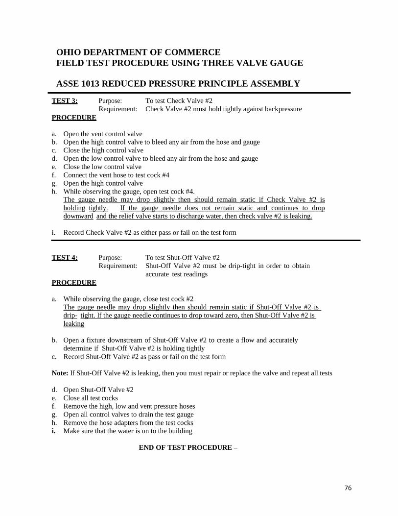
OHIO DEPARTMENT OF COMMERCE
FIELD TEST PROCEDURE USING THREE VALVE GAUGE
ASSE 1013 REDUCED PRESSURE PRINCIPLE ASSEMBLY
76
TEST 3: Purpose: To test Check Valve #2
Requirement: Check Valve #2 must hold tightly against backpressure
PROCEDURE
a. Open the vent control valve
b. Open the high control valve to bleed any air from the hose and gauge
c. Close the high control valve
d. Open the low control valve to bleed any air from the hose and gauge
e. Close the low control valve
f. Connect the vent hose to test cock #4
g. Open the high control valve
h. While observing the gauge, open test cock #4. The gauge needle may drop slightly then should remain static if Check Valve #2 is
holding tightly. If the gauge needle does not remain static and continues to drop
downward and the relief valve starts to discharge water, then check valve #2 is leaking.
i. Record Check Valve #2 as either pass or fail on the test form
TEST 4: Purpose: To test Shut-Off Valve #2
Requirement: Shut-Off Valve #2 must be drip-tight in order to obtain
accurate test readings
PROCEDURE
a. While observing the gauge, close test cock #2
The gauge needle may drop slightly then should remain static if Shut-Off Valve #2 is
drip- tight. If the gauge needle continues to drop toward zero, then Shut-Off Valve #2 is
leaking
b. Open a fixture downstream of Shut-Off Valve #2 to create a flow and accurately
determine if Shut-Off Valve #2 is holding tightly
c. Record Shut-Off Valve #2 as pass or fail on the test form
Note: If Shut-Off Valve #2 is leaking, then you must repair or replace the valve and repeat all tests
d. Open Shut-Off Valve #2
e. Close all test cocks
f. Remove the high, low and vent pressure hoses
g. Open all control valves to drain the test gauge
h. Remove the hose adapters from the test cocks
i. Make sure that the water is on to the building
END OF TEST PROCEDURE –
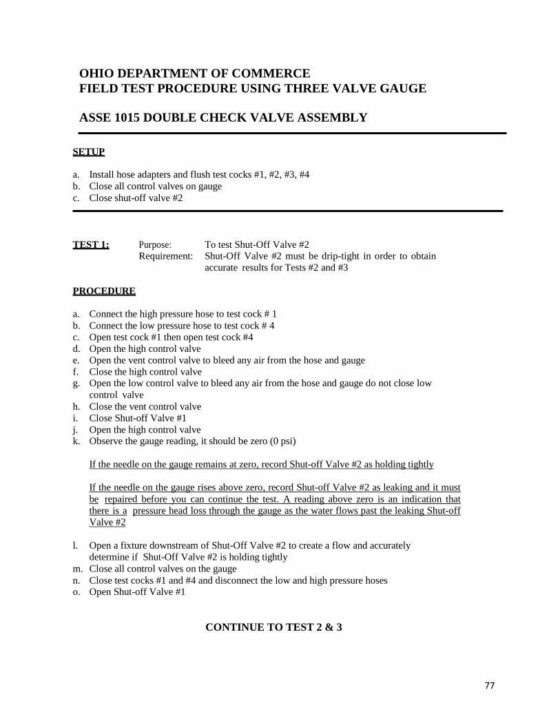
OHIO DEPARTMENT OF COMMERCE
FIELD TEST PROCEDURE USING THREE VALVE GAUGE
ASSE 1015 DOUBLE CHECK VALVE ASSEMBLY
77
SETUP
a. Install hose adapters and flush test cocks #1, #2, #3, #4
b. Close all control valves on gauge
c. Close shut-off valve #2
TEST 1: Purpose: To test Shut-Off Valve #2
Requirement: Shut-Off Valve #2 must be drip-tight in order to obtain
accurate results for Tests #2 and #3
PROCEDURE
a. Connect the high pressure hose to test cock # 1
b. Connect the low pressure hose to test cock # 4
c. Open test cock #1 then open test cock #4
d. Open the high control valve
e. Open the vent control valve to bleed any air from the hose and gauge
f. Close the high control valve g. Open the low control valve to bleed any air from the hose and gauge do not close low
control valve
h. Close the vent control valve
i. Close Shut-off Valve #1
j. Open the high control valve k. Observe the gauge reading, it should be zero (0 psi)
If the needle on the gauge remains at zero, record Shut-off Valve #2 as holding tightly
If the needle on the gauge rises above zero, record Shut-off Valve #2 as leaking and it must
be repaired before you can continue the test. A reading above zero is an indication that
there is a pressure head loss through the gauge as the water flows past the leaking Shut-off
Valve #2
l. Open a fixture downstream of Shut-Off Valve #2 to create a flow and accurately
determine if Shut-Off Valve #2 is holding tightly
m. Close all control valves on the gauge
n. Close test cocks #1 and #4 and disconnect the low and high pressure hoses o. Open Shut-off Valve #1
CONTINUE TO TEST 2 & 3

OHIO DEPARTMENT OF COMMERCE
FIELD TEST PROCEDURE USING THREE VALVE GAUGE
ASSE 1015 DOUBLE CHECK VALVE ASSEMBLY
78
TEST 2: Purpose: To test Check Valve #1
Requirement: Check Valve #1 must create a pressure differential of at
least 1 psid PROCEDURE
a. Verify that all control valves and Shut-Off Valve #2 are closed
b. Connect the high pressure hose to test cock #2
c. Connect the low pressure hose to test cock #3 d. Open test cock #3 then open test cock #2
e. Open the high control valve
f. Open the vent control valve to bleed any air from the hose and gauge
g. Close the high control valve
h. Open the low control valve to bleed any air from the hose and gauge
i. Close the low control valve.
j. Close the vent control valve
k. Observe and record the gauge reading on the test form. The gauge reading must be 1 psid or greater for check valve #1 to pass. If the gauge
needle reads less than 1 psid or continues to drop toward zero, then record check valve #1 as
fail
l. Close test cocks #2 and #3 and disconnect the low and high pressure hoses
TEST 3: Purpose: To test Check Valve #2 Requirement: Check Valve #2 must create a pressure differential of at
least 1 psid PROCEDURE
a. Connect the high hose to test cock #3
b. Connect the low hose to test cock #4
c. Open test cock #4 then open test cock #3
d. Open the high control valve
e. Open the vent control valve to bleed any air from the hose and gauge
f. Close the high control valve
g. Open the low control valve to bleed any air from the hose and gauge
h. Close the low control valve.
i. Close the vent control valve
j. Observe and record the gauge reading on the test form. The gauge reading must be 1 psi or greater for check valve #2 to pass. If the gauge needle
reads less than 1.0 psi or drops toward zero, then record check valve #2 as fail
k. Close test cocks #3 and #4 and disconnect the low and high pressure hoses
l. Open shut-off valve #2
m. Open all of the control valves to drain the water in the gauge
n. Remove the hose adapters
o. Make sure that the water is back on to the building
- END OF TEST PROCEDURE -

OHIO DEPARTMENT OF COMMERCE
FIELD TEST PROCEDURE USING THREE VALVE GAUGE
ASSE 1020 PRESSURE VACUUM BREAKER
79
SETUP
a. Install hose adapters and flush test cocks #1 and #2
b. Close all control valves on test equipment
c. Remove the air inlet canopy
TEST 1
Purpose:
To test the Air Inlet Valve
Requirement: The Air Inlet Valve must open when the pressure in the valve
body drops to 1.0 psig above atmospheric pressure, and the air
inlet valve must open fully when all of the water has drained from
the valve body.
Note: It is important that the test gauge be positioned at the same elevation as the vacuum
breaker during test #1 in order to eliminate any effect from a water column created in the hose.
PROCEDURE
a. Connect the high hose to test cock #2
b. Slowly open test cock #2 so that you do not slam the gauge needle
c. Open the high control valve
d. Open the vent control valve to bleed any air from the hose and gauge
e. Close the vent control valve
f. Close Shut-Off Valve #2
g. Close Shut-Off Valve #1
h. Slightly open the low control valve to allow the water pressure in the body of the
pressure vacuum breaker to fall slowly while observing the pressure differential gauge.
You may touch (but do not push) the air inlet valve to feel for the first movement as it opens;
in a quite area you can hear the air inlet valve open.
i. Record the pressure differential, at which the air inlet valve opened, on the test form.
The gauge reading at the point of opening must be 1 psig or greater for the air inlet valve
to pass
j. Close the low control valve
k. Close test cock #2 and disconnect the hose
l. Open Shut-Off Valve #1 quickly in order to reseat the air inlet valve and re-pressurize
the assembly
CONTINUE TO
TEST 2

OHIO DEPARTMENT OF COMMERCE
FIELD TEST PROCEDURE USING THREE VALVE GAUGE
ASSE 1020 PRESSURE VACUUM BREAKER
80
TEST 2
TEST 2:
Purpose: To test the Check Valve
Requirement: The Check Valve must be drip-tight in the normal direction of
flow when the inlet pressure is 1.0 psig and the outlet pressure is
atmospheric
PROCEDURE
a. Connect the high hose to test cock #1
b. Slowly open test cock #1 so that you do not slam the gauge needle
c. Open the vent control valve to bleed any air from the hose and gauge
d. Close the vent control valve
e. Close Shut-Off Valve #1
f. Fully open test cock #2.
This will drain the water from the body of the vacuum breaker and open the air inlet
valve. When the flow from test cock #2 stops, lift the gauge to place pressure against the
check valve in the direction of flow. The pressure reading indicated on the gauge will be
the pressure drop across the check valve.
g. Record the gauge reading on the test form.
The gauge reading must be 1 psig or greater for the check valve to pass.
h. Close test cocks #1 and #2, then disconnect the hose
i. Open Shut-off Valve #1 quickly in order to seat the air inlet valve and re-pressurize
the assembly
j. Open Shut-Off Valve #2
k. Re-install the air inlet canopy
l. Open all of the control valves to drain the water in the gauge
m. Remove the hose adapters
n. Make sure that the water is back on to the building
- END OF TEST PROCEDURE -

OHIO DEPARTMENT OF COMMERCE
FIELD TEST PROCEDURE USING THREE VALVE GAUGE
ASSE 1056 BACKSIPHONAGE VACUUM BREAKER
81
SETUP
A. Before starting test close all valves on the test gauge
B. Flush test cock before testing
Test No. # 1 - Differential Test of Check Valve
Requirement: Differential pressure across check must be 1.0 PSID or above
Step 1 Remove screws on top of hood then remove hood.
Step 2 Connect high hose of test gauge to test cock.
Step 3 Open test cock and high valve on test gauge.
Step 4 Open the vent (bypass) valve on the test gauge to bleed air from hose then close
the vent (bypass) valve on the test gauge.
Step 5 Close shut-off valve #2 then close shut-off valve #1 on backflow assembly.
Step 6 Slowly unscrew bleed screw on spill proof vacuum breaker body to relieve
pressure down stream of check and remove screw completely.
Step 7 When dripping from bleed screw stops elevate gauge about 1-2 feet above device
to remove loop in high hose. While gauge is elevated observe and record the
differential pressure.
RESULT Differential pressure on gauge must be 1.0 PSID or greater for check to
test satisfactorily.
CONTINUE TO
TEST 2

OHIO DEPARTMENT OF COMMERCE
FIELD TEST PROCEDURE USING THREE VALVE GAUGE
ASSE 1056 BACKSIPHONAGE VACUUM BREAKER
82
Note: For the following test the tester must be held at the same level as the assembly
being tested.
Test # 2 - Air Inlet - Vent Opening
Requirement: Air inlet must start to open when supply pressure is 1.0 PSI or above.
Air inlet must be fully open when supply pressure is atmospheric
Step 8 Slowly open low (needle) valve until the vent opens slightly (1/32") then close low
(needle) valve. Observe gauge and record gauge PSID. Gauge PSID must be 1.0
or greater at which vent opens to pass test as opening.
Step 9 Open low (needle) valve fully until dripping from low hose stops. While opening
low (needle) valve observe vent that it opens fully.
Step 10 Visually inspect that the vent is fully open. It must be open fully to pass
test satisfactorily.
Step 11 Replace and tighten bleed screw, close test cock and remove high hose.
Step 12 Open shut-off valve #1 and then open shut-off valve #2 to restore backflow device
to original working condition. Replace hood and screws on top of assembly.
Note: After test, all valves on test gauge must be fully open to
prevent damage to test gauge
END OF TEST PROCEDURE

OHIO DEPARTMENT OF COMMERCE
BACKFLOW PREVENTION MANUAL
83
FIVE-VALVE ANALOG TEST GAUGE
The five-valve analog gauge works exactly the same as the three-valve analog gauge. It
compares the difference between two pressures and the gauge needle indicates the difference
between the two pressures. The gauge indicates pressure in pounds and two tenths of a pound
as pounds per square inch differential or psid.
However due to the additional valves, the test steps are slightly different although the test
procedures are exactly the same.
When testing an assembly, make sure that the high-pressure, low-pressure and vent hoses
are connected to the proper test cocks. To avoid damage to the test gauge, open the test
cocks slowly when bleeding air.
This illustration is intended to familiarize you with the components of the five-valve test
gauge for your use in using the test procedures on pages 87 to 94.
High pressure bleed valve
Low pressure bleed valve
High pressure needle valve
Bypass needle valve
High pressure hose connector
Low pressure needle valve
Low pressure hose connector
Bypass hose connector

OHIO DEPARTMENT OF COMMERCE
FIELD TEST PROCEDURE USING FIVE VALVE GAUGE
ASSE 1013 REDUCED PRESSURE PRINCIPLE ASSEMBLY
84
SETUP
a. Install hose adapters and flush test cocks #2, #3, #4
b. Close all control valves on the test gauge
c. Connect the high, low and bypass hoses to the gauge
d. Close shut-off valve #2
TEST 1: Purpose: To test Check Valve #1
Requirement: Check Valve #1 must indicate a pressure differential equal PROCEDURE a. Connect the high pressure hose to test cock #2 b. Connect the low pressure hose to test cock #3
c. Open test cock #3 d. Open the low pressure bleed valve to bleed air from the hose and gauge do not close
low pressure bleed valve
e. Open test cock #2 k. Wait for the needle to stabilize, then open the high pressure bleed valve to bleed air from
the hose and gauge
l. Close the high pressure bleed valve
m. Close the low pressure bleed valve n. Observe the gauge to verify that Check Valve #1 is creating a minimum pressure
differential equal to or greater than 5 psid in order to continue the test. Record the reading
on the test form.
TEST 2: Purpose: To test the Pressure Differential Relief Valve
Requirement: The Relief Valve must maintain a pressure differential of at
least 2 psid between the Relief Valve Zone and the supply
pressure PROCEDURE
a. Open the high pressure needle valve
b. Slightly open the low control valve to slowly increase the water pressure in the intermediate pressure zone, the gauge needle should begin to drop toward zero and observe when water first begins to discharge from the relief port.
c. Observe the gauge reading at which this discharge is first occurring and record the psid
reading shown on the gauge.
d. Record the Relief Valve as passed if water discharged at 2 psid or greater
e. Compare the gauge reading obtained for Check Valve #1 and the Relief Valve. The
Check Valve #1 psid must be 3psi or greater than the Relief Valve psid for Check Valve #1
to pass.
f. Close the high and low control valves
CONTINUE TO TEST 3 & 4

OHIO DEPARTMENT OF COMMERCE
FIELD TEST PROCEDURE USING FIVE VALVE GAUGE
ASSE 1013 REDUCED PRESSURE PRINCIPLE ASSEMBLY
85
TEST 3: Purpose: To test Check Valve #2
Requirement: Check Valve #2 must hold tightly against backpressure
PROCEDURE
a. Loosely connect the bypass (vent) hose to test cock #4
b. Open the vent control valve
c. Open the low control valve to bleed any air from the hose and gauge
d. Close the low control valve
e. Tighten the bypass (vent) hose to test cock #4
f. Open the high control valve
g. While observing the gauge, open test cock #4. The gauge needle may drop slightly then should remain static if Check Valve #2 is
holding tightly. If the gauge needle does not remain static and continues to drop
downward and the relief valve starts to discharge water, then check valve #2 is leaking.
h. Record Check Valve #2 as either pass or fail on the test form
TEST 4: Purpose: To test Shut-Off Valve #2
Requirement: Shut-Off Valve #2 must be drip-tight in order to obtain
accurate test readings
PROCEDURE
a. While observing the gauge, close test cock #2
The gauge needle may drop slightly then should remain static if Shut-Off Valve #2 is
drip- tight. If the gauge needle continues to drop toward zero, then Shut-Off Valve #2 is
leaking
b. Open a fixture downstream of Shut-Off Valve #2 to create a flow and accurately
determine if Shut-Off Valve #2 is holding tightly
c. Record Shut-Off Valve #2 as pass or fail on the test form
Note: If Shut-Off Valve #2 is leaking, then you must repair or replace the valve and repeat all tests
d. Open Shut-Off Valve #2
e. Close all test cocks
f. Remove the high, low and bypass hoses
g. Open all control valves to drain the test gauge
h. Remove the hose adapters from the test cocks
i. Make sure that the water is on to the building
- END OF TEST PROCEDURE –

OHIO DEPARTMENT OF COMMERCE
FIELD TEST PROCEDURE USING FIVE VALVE GAUGE
ASSE 1015 DOUBLE CHECK VALVE ASSEMBLY
86
SETUP
a. Install hose adapters and flush test cocks #1, #2, #3, #4
b. Connect the high, low and bypass hoses to the gauge
c. Close all control valves on gauge
d. Close shut-off valve #2
TEST 1: Purpose: To test Shut-Off Valve #2
Requirement: Shut-Off Valve #2 must be drip-tight in order to obtain
accurate results for Tests #2 and #3
PROCEDURE
a. Connect the high pressure hose to test cock # 1
b. Connect the low pressure hose to test cock # 4
c. Open test cock #4 d. Open the low pressure bleed valve to bleed air from the hose and gauge do not close
low control valve
e. Open test cock #1 f. Allow the gauge needle to stabilize, then open the high pressure bleed valve to bleed air
from the hose and gauge
g. Close the high pressure bleed valve
h. Close the low pressure bleed valve
i. Close Shut-off Valve #1
j. Open the high pressure needle valve one turn
k. Open the low pressure needle valve one turn
l. Loose then retighten the hose connection at test cock #4 to bleed air from the gauge manifold m. Observe the gauge reading, it should be zero (0 psi)
If the needle on the gauge remains at zero, record Shut-off Valve #2 as holding tightly
If the needle on the gauge rises above zero, record Shut-off Valve #2 as leaking and it must
be repaired before you can continue the test. A reading above zero is an indication that
there is a pressure head loss through the gauge as the water flows past the leaking Shut-off
Valve #2
n. Open a fixture downstream of Shut-Off Valve #2 to create a flow and accurately
determine if Shut-Off Valve #2 is holding tightly
o. Close all control valves on the gauge
p. Close test cocks #1 and #4 and disconnect the low and high pressure hoses q. Open Shut-off Valve #1
CONTINUE TO TEST 2 & 3
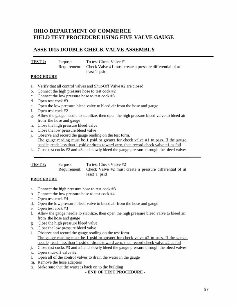
OHIO DEPARTMENT OF COMMERCE
FIELD TEST PROCEDURE USING FIVE VALVE GAUGE
ASSE 1015 DOUBLE CHECK VALVE ASSEMBLY
87
TEST 2: Purpose: To test Check Valve #1
Requirement: Check Valve #1 must create a pressure differential of at
least 1 psid
PROCEDURE
a. Verify that all control valves and Shut-Off Valve #2 are closed
b. Connect the high pressure hose to test cock #2 c. Connect the low pressure hose to test cock #3
d. Open test cock #3
e. Open the low pressure bleed valve to bleed air from the hose and gauge
f. Open test cock #2 g. Allow the gauge needle to stabilize, then open the high pressure bleed valve to bleed air
from the hose and gauge
h. Close the high pressure bleed valve
i. Close the low pressure bleed valve
j. Observe and record the gauge reading on the test form. The gauge reading must be 1 psid or greater for check valve #1 to pass. If the gauge
needle reads less than 1 psid or drops toward zero, then record check valve #1 as fail
k. Close test cocks #2 and #3 and slowly bleed the gauge pressure through the bleed valves
TEST 3: Purpose: To test Check Valve #2 Requirement: Check Valve #2 must create a pressure differential of at
least 1 psid
PROCEDURE
a. Connect the high pressure hose to test cock #3
b. Connect the low pressure hose to test cock #4
c. Open test cock #4
d. Open the low pressure bleed valve to bleed air from the hose and gauge
e. Open test cock #3
f. Allow the gauge needle to stabilize, then open the high pressure bleed valve to bleed air
from the hose and gauge
g. Close the high pressure bleed valve
h. Close the low pressure bleed valve
i. Observe and record the gauge reading on the test form.
The gauge reading must be 1 psid or greater for check valve #2 to pass. If the gauge
needle reads less than 1 psid or drops toward zero, then record check valve #2 as fail
j. Close test cocks #3 and #4 and slowly bleed the gauge pressure through the bleed valves
k. Open shut-off valve #2
l. Open all of the control valves to drain the water in the gauge
m. Remove the hose adapters n. Make sure that the water is back on to the building
- END OF TEST PROCEDURE -
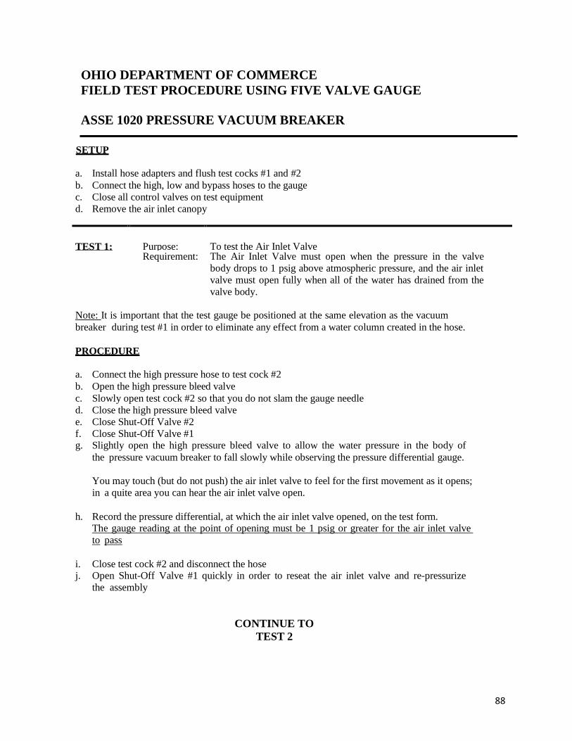
OHIO DEPARTMENT OF COMMERCE
FIELD TEST PROCEDURE USING FIVE VALVE GAUGE
ASSE 1020 PRESSURE VACUUM BREAKER
88
SETUP
a. Install hose adapters and flush test cocks #1 and #2
b. Connect the high, low and bypass hoses to the gauge
c. Close all control valves on test equipment
d. Remove the air inlet canopy
TEST 1:
Purpose:
To test the Air Inlet Valve
Requirement: The Air Inlet Valve must open when the pressure in the valve
body drops to 1 psig above atmospheric pressure, and the air inlet
valve must open fully when all of the water has drained from the
valve body.
Note: It is important that the test gauge be positioned at the same elevation as the vacuum
breaker during test #1 in order to eliminate any effect from a water column created in the hose.
PROCEDURE
a. Connect the high pressure hose to test cock #2
b. Open the high pressure bleed valve
c. Slowly open test cock #2 so that you do not slam the gauge needle
d. Close the high pressure bleed valve
e. Close Shut-Off Valve #2
f. Close Shut-Off Valve #1 g. Slightly open the high pressure bleed valve to allow the water pressure in the body of
the pressure vacuum breaker to fall slowly while observing the pressure differential gauge.
You may touch (but do not push) the air inlet valve to feel for the first movement as it opens;
in a quite area you can hear the air inlet valve open.
h. Record the pressure differential, at which the air inlet valve opened, on the test form. The gauge reading at the point of opening must be 1 psig or greater for the air inlet valve
to pass
i. Close test cock #2 and disconnect the hose j. Open Shut-Off Valve #1 quickly in order to reseat the air inlet valve and re-pressurize
the assembly
CONTINUE TO
TEST 2

OHIO DEPARTMENT OF COMMERCE
FIELD TEST PROCEDURE USING FIVE VALVE GAUGE
ASSE 1020 PRESSURE VACUUM BREAKER
89
TEST 2:
Purpose:
Requirement:
Purpose: To test the Check Valve The Check Valve must be drip-tight in the normal direction of
TEST 2
TEST 2:
Purpose: To test the Check Valve
Requirement: The Check Valve must be drip-tight in the normal direction of
flow when the inlet pressure is 1.0 psig and the outlet pressure is
atmospheric
PROCEDURE
a. Connect the high pressure hose to test cock #1
b. Open the high pressure bleed valve
c. Slowly open test cock #1 so that you do not slam the gauge needle
d. Close the high pressure bleed valve
e. Close Shut-Off Valve #1
f. Fully open test cock #2.
This will drain the water from the body of the vacuum breaker and open the air inlet
valve. When the flow from test cock #2 stops, lift the gauge to place pressure against the
check valve in the direction of flow. The pressure reading indicated on the gauge will be
the pressure drop across the check valve.
g. Record the gauge reading on the test form.
The gauge reading must be 1 psig or greater for the check valve to pass.
h. Close test cocks #1 and #2, then disconnect the hose
i. Open Shut-off Valve #1 quickly in order to seat the air inlet valve and re-pressurize
the assembly
j. Open Shut-Off Valve #2
k. Re-install the air inlet canopy
l. Open all of the needle valves to drain the water in the gauge
m. Remove the hose adapters
n. Make sure that the water is back on to the building
- END OF TEST PROCEDURE -

OHIO DEPARTMENT OF COMMERCE
FIELD TEST PROCEDURE USING FIVE VALVE GAUGE
ASSE 1056 BACKSIPHONAGE VACUUM BREAKER
90
SETUP
A. Before starting test close all valves on the test gauge
B. Flush test cock before testing
Test No. # 1 - Differential Test of Check Valve
Requirement: Differential pressure across check must be 1.0 PSID or above
Step 1 Remove screws on top of hood then remove hood.
Step 2 Connect high hose of test gauge to test cock.
Step 3 Open test cock and high valve on test gauge.
Step 4 Open high pressure bleed valve on test gauge to bleed air from hose then close
high pressure bleed valve on test gauge.
Step 5 Close shut-off valve #2 then close shut-off valve #1 on backflow assembly.
Step 6 Slowly unscrew bleed screw on spill proof vacuum breaker body to relieve
pressure down stream of check and remove screw completely.
Step 7 When dripping from bleed screw stops elevate gauge about 1-2 feet above device
to remove loop in high hose. While gauge is elevated observe and record the
differential pressure.
RESULT Differential pressure on gauge must be 1.0 PSID or greater for check to
test satisfactorily.
CONTINUE TO
TEST 2

91
OHIO DEPARTMENT OF COMMERCE
FIELD TEST PROCEDURE USING FIVE VALVE GAUGE
ASSE 1056 BACKSIPHONAGE VACUUM BREAKER
Note: For the following test the tester must be held at the same level as the assembly
being tested.
Test # 2 - Air Inlet - Vent Opening
Requirement: Air inlet must start to open when supply pressure is 1.0 PSI or above.
Air inlet must be fully open when supply pressure is atmospheric
Step 8 Slowly open low (needle) valve until the vent opens slightly (1/32") then close low
(needle) valve. Observe gauge and record gauge PSID. Gauge PSID must be 1.0
or greater at which vent opens to pass test as opening.
Step 9 Open low (needle) valve fully until dripping from low hose stops. While opening
low (needle) valve observe vent that it opens fully.
Step 10 Visually inspect that the vent is fully open. It must be open fully to pass
test satisfactorily.
Step 11 Replace and tighten bleed screw, close test cock and remove high hose.
Step 12 Open shut-off valve #1 and then open shut-off valve #2 to restore backflow device
to original working condition. Replace hood and screws on top of assembly.
Note: After test, all valves on test gauge must be fully open to
prevent damage to test gauge
END OF TEST PROCEDURE

92
STATE OF OHIO Annual Test & Maintenance Report for Backflow Prevention Assemblies
Facility Name:_______________________________________ Contact Person______________________________
Complete Address: ______________________________________________________________________________
Assembly Information Installation Information Containment □ Isolation □
Make_____________________________ Meter Pit □ Basement □ Floor Number ________
Model_______________Size__________ Penthouse □ Boiler Room □ Room Number _______
Serial Number______________________ Mechanical Room □ Protection Provided________________________
Double Check Assembly Reduced Pressure Assembly Pressure Vacuum Breaker Initial
Test Outlet Valve
Pass
Fail
1st Check Valve
___ psid
Pass
Fail
Air Inlet Valve
___ psig
Pass
Fail 1st
Check Valve
__psid
Pass
Fail
Relief Valve Opening Point
___ psid
Pass
Fail
Check Valve
___ psig
Pass
Fail
2nd Check Valve
__psid
Pass
Fail
2nd Check Valve
Pass
Fail
Outlet Valve Pass Fail
Repairs & Materials Used
Re-Test
After
Repair
Outlet Valve
Pass
Fail
1st Check Valve
___ psid
Pass
Fail
Air Inlet Valve
___ psig
Pass
Fail
1st Check Valve
__psid
Pass
Fail
Relief Valve Opening Point
___ psid
Pass
Fail
Check Valve
___ psig
Pass
Fail
2nd Check Valve
__psid
Pass
Fail
2nd Check Valve
Pass
Fail
Outlet Valve Pass Fail
TESTER CERTIFICATION: I hereby certify that the above data is correct and that the backflow prevention device is in proper working condition.
Tester Name (Printed) ___________________________________ Signature ___________________________________
Company Name ___________________________________ Ohio Cert. No. _________ Contractor No. ______________ I hereby certify that the above backflow prevention device has been in constant use at this location during the entire prescribed interval between test periods and during that period this device was not bypassed, made inoperative, or removed without proper authorization. I further certify that I have the authority and responsibility to ensure the above.
Owner/Officer (Printed) __________________________________ Signature __________________________________ Title: ________________________________________________________________ Date: ______________________
Comments:

93
DEPARTMENT OF COMMERCE
BACKFLOW PREVENTION MANUAL
TEST GAUGE
The test gauge should be carried in a sturdy case and protected from freezing conditions. If you suspect that the gauge has been damaged, from dropping or freezing, then the gauge should be re-calibrated before being used.
There currently is no State requirement that the gauge must be re-calibrated annually, but this is a recommended practice.
The calibration is required under the authority having jurisdiction and the tester shall be familiar with the requirements of the local authority when and how often test gauges need recalibration.

94
DEPARTMENT OF COMMERCE
BACKFLOW PREVENTION MANUAL
TESTER SAFETY
All safety precautions as outlined in the applicable OSHA subpart sections should be
followed when working from ladders, in confined spaces and other working conditions
covered by OSHA regulations.
You should test the atmosphere in a pit before entering to determine that the oxygen levels
are appropriate. Additionally, many companies will require the use of approved safety apparatus
if you are entering a “confined space”. Check with the company contact person before entering a
confined space.
Oxygen sensors are commercially available for testing the atmosphere. Keep in mind that if you
are going to invest the money in a sensor then you may want to invest a little more and
purchase a sensor that detects oxygen, methane gas, carbon dioxide, and explosive or flammable
gases.
You will have to repair a backflow prevention device if it fails your test. For the safety of
your customer, it is recommended that you have appropriate repair parts with you or ready
access to repair parts so that you can return the backflow preventer to service after the test.
When you have to repair a backflow preventer, you must exercise caution when removing the
cap to gain access to the check valve. Remember that the spring may be tensioned against the
cap and will be exerting pressure against it.
This is especially important when removing the cap from a device that is greater than two inches
in size. It is recommended that you carry two long bolts in your toolbox. You may then
remove two bolts from the cap and insert the longer bolts. You may then remove the remaining
bolts safely and slowly back-out the two longer bolts. The spring tension against the cap is
relieved when you can push the cap downward with your hands.
Often backflow prevention devices are not easily accessible (this writer has seen them
installed thirty feet in the air). Remember when you install a backflow prevention device that
you may be the one who is also asked to test or repair it.
The water supplier will have specific installation requirements for a containment principle
backflow prevention device. Check with the water supplier before beginning the installation.
There are few installation requirements for an isolation device at present. These should be
installed according to the applicable plumbing code installation requirement or the
manufacturer’s recommendations if there is no direction in the plumbing code.
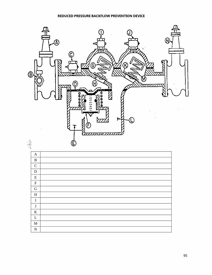
95
REDUCED PRESSURE BACKFLOW PREVENTION DEVICE
A
B
C
D
E
F
G
H
I
J
K
L
M
N
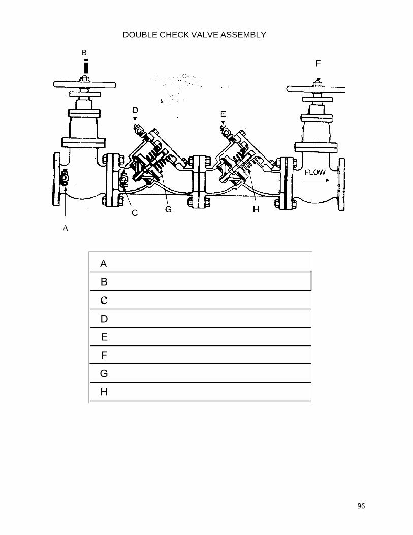
96
DOUBLE CHECK VALVE ASSEMBLY
B
A
F
. ·:: ·.. .
A
E

97
I NAME I PRESSURE VACUUM BREAKER
F
E