Embed Size (px)
Citation preview

R-14-01-090112
6BMM
USER'S MANUAL
1. System power on by PS/2 Mouse: First, enable this functionin CMOS Setup, then you can power on the system by doubleclicking the right or left button of your PS/2 Mouse.
2. System power on by Keyboard: If your ATX power supplysupports larger than 300 mA 5V Stand-By current(dependenton the specification of keyboards), you can power on yoursystem by entering password from the Keyboard aftersetting the “Keyboard power on” jumper (JP1) and passwordin CMOS Setup.
3. Support Modem Ring-On. (Include internal Modem andexternal modem on COM A and COM B)
4. Support Wake-up On LAN. (Your ATX power supply mustsupport larger than 720 mA 5V Stand-By current)
5. ATI RAGE PRO AGP Display Onboard. (8M SDRAM)
6. YAMAHA PCI Sound Onboard.
7. Support STR Function (Optional).
For Intel Pentium II / CeleronTM Processor MAINBOARD

REV. 1.4 First Edition

6BMM
1
The author assumes no responsibility for any errors or omissions that mayappear in this document nor does it make a commitment to update theinformation contained herein.
Third-party brands and names are the property of their respective owners.
January 12, 1999 Taipei, Taiwan

Quick Installation Guide
2
I. Quick Installation Guide :
CPU SPEED SETUP
The default system bus speed is set 66/100MHz (SW2). The user canchange the DIP SWITCH (SW1) selection to set up the CPU speed for 233- 366MHz processor.
M The CPU speed must match with the frequency RATIO. It will causesystem hanging up if the frequency RATIO is higher than that of CPU.
SW1:
CLK RATIO 1 2 3 4X3 ON OFF ON ON
X3.5 OFF OFF ON ONX4 ON ON OFF ON
X4.5 OFF ON OFF ONX5 ON OFF OFF ON
X5.5 OFF OFF OFF ONX6 ON ON ON OFFX6.5 OFF ON ON OFF
Set System Bus Speed
SW2:
CPU AGP PCI 1 2 3 466 66 33.4 ON OFF OFF ON75 75 37.5 ON ON OFF ON83 83 41.6 ON OFF ON ON
100 66 33.4 OFF OFF OFF OFF112 75 37.5 OFF ON OFF OFF133 89 33.3 OFF OFF ON OFF
«Note: We don’t recommend you to setup your system speed to 75, 83,112 or 133MHz because these frequencies are not the standardspecifications for CPU, Chipset and most of the peripherals.Whether your system can run under 75, 83, 112 or 133MHzproperly will depend on your hardware configurations: CPU,SDRAM, Cards, etc.

6BMM
3
1. Pentium II / Celeron 233 MHz / 66MHz FSB
6BMM
YAMAHA
INTEL443BXATi
3D RAGE PROAGP 2X
PIIX4
4 3 2 1
SW2
ON
BIOS
4 3 2 1
ON
SW1
2. Pentium II / Celeron 266MHz / 66MHz FSB
3. Pentium II / Celeron 300MHz / Celeron 300A MHz / 66MHz FSB
4 3 2 1
SW1ON
OFFSW2
ON
4 3 2 1
OFF
SW1 ON
4 3 2 1OFF SW2
ON
4 3 2 1
OFF
Quick Installation Guide
4
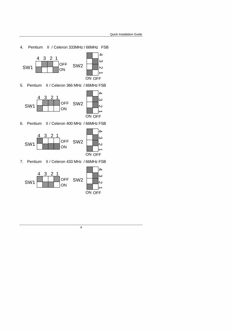
4. Pentium II / Celeron 333MHz / 66MHz FSB
5. Pentium II / Celeron 366 MHz / 66MHz FSB
6. Pentium II / Celeron 400 MHz / 66MHz FSB
7. Pentium II / Celeron 433 MHz / 66MHz FSB
SW1 ON
4 3 2 1OFF SW2
ON
4 3 2 1
OFF
SW2
ON
4 3 2 1
OFF
SW1ON
4 3 2 1OFF
SW2
ON
4 3 2 1
OFF
SW1ON
4 3 2 1OFF
SW2
ON
4 3 2 1
OFF
SW1ON
4 3 2 1OFF

6BMM
5
8. Pentium II 350MHz / 100MHz FSB
9. Pentium II 400MHz / 100MHz FSB
10. Pentium II 450MHz / 100MHz FSB
11. Pentium II 500MHz / 100MHz FSB
SW2
ON
4 3 2 1
OFF
SW2
ON
4 3 2 1
OFF
SW1 ON
4 3 2 1OFF
SW1 ON
4 3 2 1OFF
SW2
ON
4 3 2 1
OFF
SW1 ON
4 3 2 1OFF
SW2
ON
4 3 2 1
OFF
SW1 ON
4 3 2 1OFF
Quick Installation Guide
6
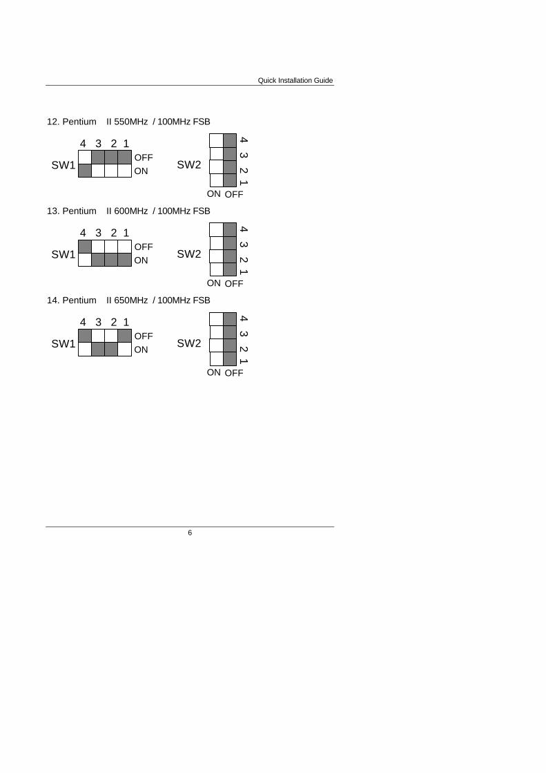
12. Pentium II 550MHz / 100MHz FSB
13. Pentium II 600MHz / 100MHz FSB
14. Pentium II 650MHz / 100MHz FSB
SW2
ON
4 3 2 1
OFF
SW1 ON
4 3 2 1OFF
SW2
ON
4 3 2 1
OFF
SW1 ON
4 3 2 1OFF
SW2
ON
4 3 2 1
OFF
SW1 ON
4 3 2 1OFF

6BMM
7
II. Jumper setting :GN : Green Function Switch
6BMM
YAMAHA
INTEL443BXATi
3D RAGE PROAGP 2X
PIIX4SW2
BIOSSW1
Open:Normaloperation
Short:EnteringGreenmode
GD : Green Function LED
6BMM
YAMAHA
INTEL443BXATi
3D RAGE PROAGP 2X
PIIX4SW2
BIOSSW1
1
PIN FUNCTION1 LED (+)2 LED (-)

Quick Installation Guide
8
HD : IDE Hard Disk Active LED
6BMM
YAMAHA
INTEL443BXATi
3D RAGE PROAGP 2X
PIIX4SW2
BIOSSW1
1
PIN FUNCTION1 LED (+)2 LED (-)
SPKR : External Speaker/ Internal Buzzer Connector
6BMM
YAMAHA
INTEL443BXATi
3D RAGE PROAGP 2X
PIIX4SW2
BIOSSW1
PIN FUNCTION1 VCC2 VCC3 Data4 Data
1
+
External Speak
1
+
Default :Internal Buzzer
Buzzer

6BMM
9
RES : Reset Switch
6BMM
YAMAHA
INTEL443BXATi
3D RAGE PROAGP 2X
PIIX4SW2
BIOSSW1
Open:Normaloperation
Short:Reset system
PWR : Power LED Connector (as 3 steps ACPI LED)
6BMM
YAMAHA
INTEL443BXATi
3D RAGE PROAGP 2X
PIIX4SW2
BIOSSW1
1
PIN FUNCTION1 LED (+)2 LED (-)3 LED (-)

Quick Installation Guide
10
Soft PWR : Soft Power Connector
6BMM
YAMAHA
INTEL443BXATi
3D RAGE PROAGP 2X
PIIX4SW2
BIOSSW1
1
PIN FUNCTION1 Signal2 GND
IR : Infrared Connector (Optional)
6BMM
YAMAHA
INTEL443BXATi
3D RAGE PROAGP 2X
PIIX4SW2
BIOSSW1
Pin No.
1
2
3
4
5
IR DataOutput
GND
IR DataInput
NC
POWER (+)
Function
+
1

6BMM
11
JP14:CLEAR CMOS FUNCTION
6BMM
YAMAHA
INTEL443BXATi
3D RAGE PROAGP 2X
PIIX4SW2
BIOSSW1
1 1-2 Short :Clear CMOS2-3 Short :NormalDefault: 2-3 Short
When you will Clear CMOS, pleaseremove AC Power (110V/220V).
M
PS/2 Mouse / Keyboard Connector
6BMM
YAMAHA
INTEL443BXATi
3D RAGE PROAGP 2X
PIIX4SW2
BIOSSW1
Pin No. Function1
2
3
4
5 Clock
Data
NC
VCC (+5V)
GND
PS/2Mouse/Keyboard
6 NC
PS/2 Keyboard
PS/2 Mouse

Quick Installation Guide
12
CPU FAN : CPU Cooling Fan Power Connector
6BMM
YAMAHA
INTEL443BXATi
3D RAGE PROAGP 2X
PIIX4SW2
BIOSSW1
1
Pin No. Function123
GND+12V
SENSE
Power FAN : Power Fan Power Connector
6BMM
YAMAHA
INTEL443BXATi
3D RAGE PROAGP 2X
PIIX4SW2
BIOSSW1
1
Pin No. Function123
GND+12V
SENSE

6BMM
13
System FAN : System Fan Power Connector
6BMM
YAMAHA
INTEL443BXATi
3D RAGE PROAGP 2X
PIIX4SW2
BIOSSW1
1
Pin No. Function123
GND+12V
SENSE
IDE1: For Primary IDE port
6BMM
YAMAHA
INTEL443BXATi
3D RAGE PROAGP 2X
PIIX4SW2
BIOSSW1
1
RED LINE

Quick Installation Guide
14
IDE2: For Secondary IDE port
6BMM
YAMAHA
INTEL443BXATi
3D RAGE PROAGP 2X
PIIX4SW2
BIOSSW1
1
RED LINE
FLOPPY : FLOPPY PORT
6BMM
YAMAHA
INTEL443BXATi
3D RAGE PROAGP 2X
PIIX4SW2
BIOSSW1
1
RED LINE

6BMM
15
ATX POWER : ATX POWER Connector
6BMM
YAMAHA
INTEL443BXATi
3D RAGE PROAGP 2X
PIIX4SW2
BIOSSW1
Pin No. Function
3,5,7,13,15-17
4,6,19,20
GND
10
12
18
8
+12V
-12V
-5V
VCC (+5V)
Power Good
9
14
5V SB (Stand by+5V)
PS-ON(Soft ON/OFF)
1
11
LPT PORT / COM A / COM B / VGA PORT
6BMM
YAMAHA
INTEL443BXATi
3D RAGE PROAGP 2X
PIIX4SW2
BIOSSW1
COM A
LPT PORT
VGA PORT
COM B
n n n n nn n n n n
1

Quick Installation Guide
16
GAME & AUDIO PORT
6BMM
YAMAHA
INTEL443BXATi
3D RAGE PROAGP 2X
PIIX4SW2
BIOSSW1
MICGAME
Line InLine Out
JP1 : Keyboard Power On
6BMM
YAMAHA
INTEL443BXATi
3D RAGE PROAGP 2X
PIIX4SW2
BIOSSW1
1-2 2-3
EnableDisable
123
JP1
Default : 2-3 short

6BMM
17
USB: USB Port
6BMM
YAMAHA
INTEL443BXATi
3D RAGE PROAGP 2X
PIIX4SW2
BIOSSW1
Pin No. Function
1
2
3
4
5
6
7
8
USB D0-
USB D0+
GND
USB V0
GND
USB V1
USB D1-
USB D1+
JP7: Wake on LAN
6BMM
YAMAHA
INTEL443BXATi
3D RAGE PROAGP 2X
PIIX4SW2
BIOSSW1
1
Pin No. Function
123
+5V SBGND
Signal

Quick Installation Guide
18
CN6 &JP5:CD Audio Line In
6BMM
YAMAHA
INTEL443BXATi
3D RAGE PROAGP 2X
PIIX4SW2
BIOSSW1
1 JP 5R G G L
1 CN 6G R G L
JP9: Onboard Sound Function Selection
6BMM
YAMAHA
INTEL443BXATi
3D RAGE PROAGP 2X
PIIX4SW2
BIOSSW1
1
JP9
Default: 1-2 short
1-2: OnboardSound Enabled
2-3: OnboardSound Disabled

6BMM
19
JP8: Onboard VGA Interrupt Function Selection
6BMM
YAMAHA
INTEL443BXATi
3D RAGE PROAGP 2X
PIIX4SW2
BIOSSW1
1
JP8
Default: 1-2 short
1-2: Disable VGA INT
2-3: Enable VGA INT
JP12: Onboard VGA Function Selection
6BMM
YAMAHA
INTEL443BXATi
3D RAGE PROAGP 2X
PIIX4SW2
BIOSSW1
1
JP12
Default: 2-3 short
1-2: Onboard VGADisabled
2-3: Onboard VGAEnabled
Quick Installation Guide
20
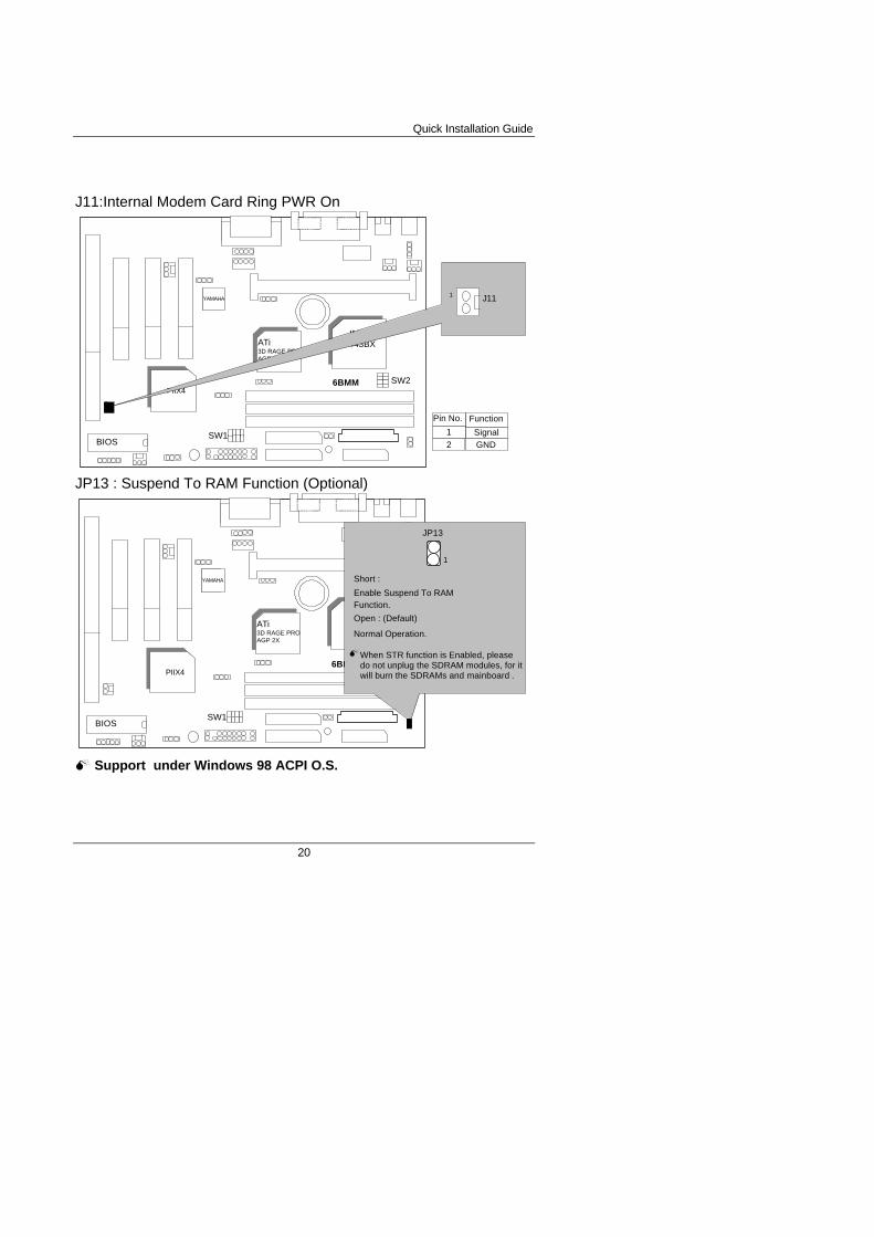
J11:Internal Modem Card Ring PWR On
6BMM
YAMAHA
INTEL443BXATi
3D RAGE PROAGP 2X
PIIX4SW2
BIOSSW1
J111
Pin No. Function
12
SignalGND
JP13 : Suspend To RAM Function (Optional)
6BMM
YAMAHA
INTEL443BXATi
3D RAGE PROAGP 2X
PIIX4SW2
BIOSSW1
Short :
Enable Suspend To RAMFunction.
Open : (Default)
Normal Operation.
JP13
1
When STR function is Enabled, pleasedo not unplug the SDRAM modules, for itwill burn the SDRAMs and mainboard .
M
M Support under Windows 98 ACPI O.S.
6BMM
21
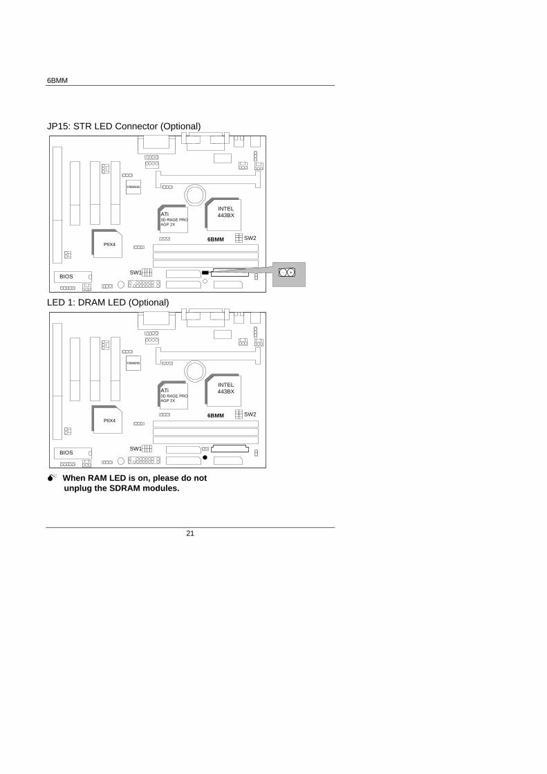
JP15: STR LED Connector (Optional)
6BMM
YAMAHA
INTEL443BXATi
3D RAGE PROAGP 2X
PIIX4SW2
BIOSSW1 +−
LED 1: DRAM LED (Optional)
6BMM
YAMAHA
INTEL443BXATi
3D RAGE PROAGP 2X
PIIX4SW2
BIOSSW1
M When RAM LED is on, please do not unplug the SDRAM modules.

Quick Installation Guide
22
JP11: System Acceleration
6BMM
YAMAHA
INTEL443BXATi
3D RAGE PROAGP 2X
PIIX4SW2
BIOSSW1
1 1-2 Turbo2-3 100MHz NormalDefault: 2-3 100MHz Normal
1-2 Turbo:For 100MHz Turboand other frequencies
2-3 100MHz Normal:For 100MHz Normal
BAT1:For Battery
6BMM
YAMAHA
INTEL443BXATi
3D RAGE PROAGP 2X
PIIX4SW2
BIOSSW1
BAT+
MDanger of explosion if battery is incorrectly replaced.MReplace only with the same or equivalent type recommended by the manufacturer.

6BMM
23
MDispose of used batteries according to the manufacturer’ s instructions.
Quick Installation Guide
24
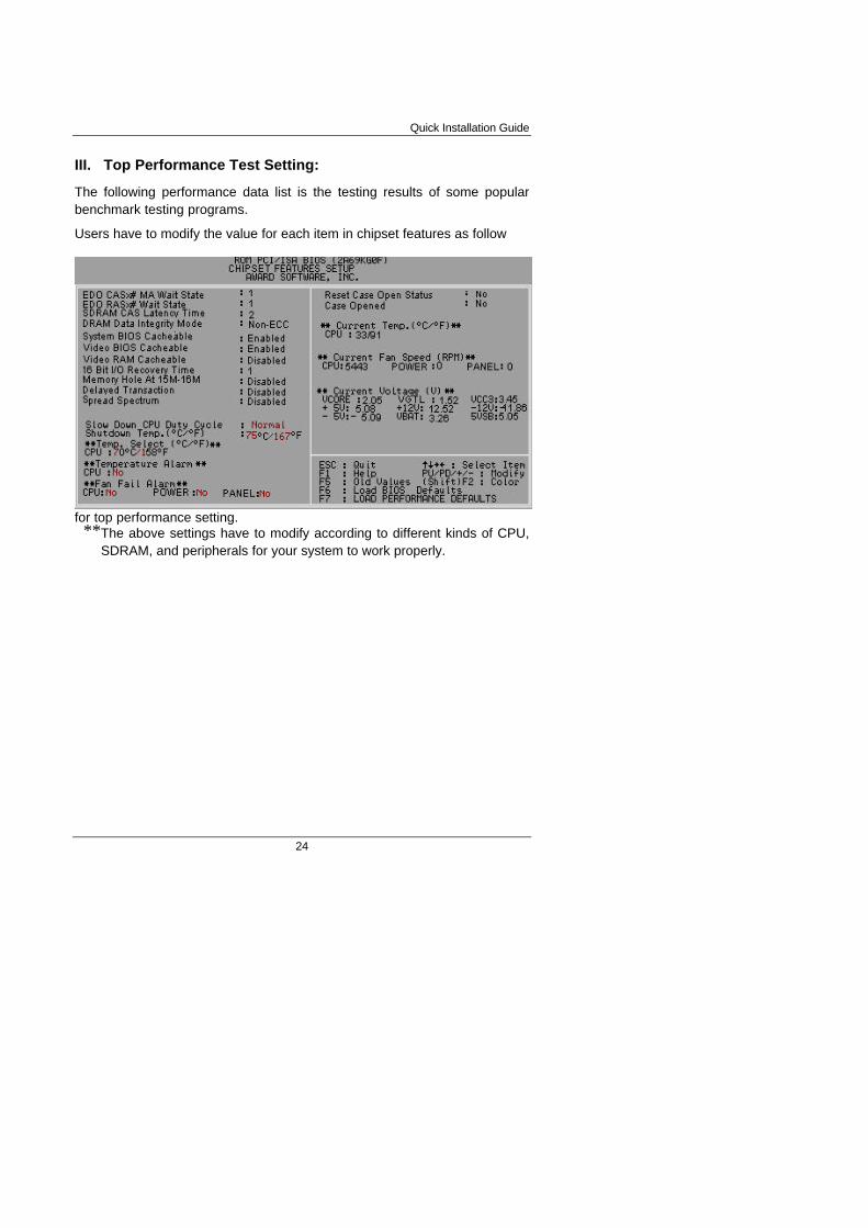
III. Top Performance Test Setting:
The following performance data list is the testing results of some popularbenchmark testing programs.
Users have to modify the value for each item in chipset features as follow
for top performance setting.**The above settings have to modify according to different kinds of CPU,
SDRAM, and peripherals for your system to work properly.

6BMM
25
These data are just referred by users, and there is no responsibility for differenttesting data values gotten by users. (The different Hardware & Softwareconfiguration will result in different benchmark testing results.)
• CPU Pentium II processor
• DRAM (128 x 1) MB SDRAM (SEC KM48S8030BT-GH)
• CACHE SIZE 512 KB included in CPU
• DISPLAY Onboard ATi AGP 3D graphics acceleration chip (8MBSDRAM)
• STORAGE Onboard IDE (Seagate ST34520A)
• O.S. Windows NT™ 4.0
• DRIVER Display Driver at 1024 x 768 x 64k colors x 75Hz.
TRIONES Bus Master IDE Driver 3.70
Intel Pentium IIProcessor
350MHz(100x3.5) 450MHz(100x4.5)
Winbench98
CPU mark32 909 1130
FPU Winmark 1810 2300
Business Disk 2130 2160
Hi-End Disk 5160 5270
Business Graphics 183 210
Hi-End Graphics 206 246
Winstone98
Business 33.8 37.6
Hi-End 39.1 43.4