Embed Size (px)
Citation preview

1
© 2005 Burkhard Stiller and Jochen Schiller FU Berlin M7 – 1
7. Wireless Local Area Networks
CharacteristicsIEEE 802.11
HIPERLAN, WATM, BRAN, HIPERLAN2Bluetooth
RFComparison
© 2005 Burkhard Stiller and Jochen Schiller FU Berlin M7 – 2
Characteristics of Wireless LANs
Advantages:– Very flexible within the reception area – Ad-hoc networks without previous planning possible– (Almost) no wiring difficulties:
• E.g., historic buildings, firewalls– More robust against disasters like:
• E.g., earthquakes, fire - or users pulling a plug– Quite cheap networking infrastructures possible
Drawbacks:– Typically very low bandwidth compared to wired networks: 1-10 Mbit/s and error
rates of about 10-4 instead of 10-12
– Many proprietary solutions, especially for higher bit-rates:• Standards take their time, e.g., IEEE 802.11
– Products have to follow many national restrictions if working wireless:• It takes a vary long time to establish global solutions like, e.g., IMT-2000
– Lack of security, “open” air interface, War Driving

2
© 2005 Burkhard Stiller and Jochen Schiller FU Berlin M7 – 3
Design Goals for Wireless LANs
Global, seamless operationLow power for battery use No special permissions or licenses needed to use the LAN Robust transmission technologySimplified spontaneous co-operation at meetings Easy to use for everyone, simple management Protection of investment in wired networks Security:– No one should be able to read my data
Privacy:– No one should be able to collect user profiles
Safety, low radiationTransparency concerning applications and higher layer protocols, but also location awareness if necessary
© 2005 Burkhard Stiller and Jochen Schiller FU Berlin M7 – 4
Comparison: Infrared vs. Radio Transmission
Infrared:– Uses IR diodes, multiple reflections,
diffuse light, e.g., walls or furniture
Advantages:– Simple, cheap, available in many mobile
devices– No licenses needed– Simple shielding possible
Drawbacks:– Interference by sunlight, heat sources– Many things shield/absorb IR light, LoS – Low bandwidth (115 kbit/s … 4 Mbit/s)
Example:– IrDA (Infrared Data Association)
interface available everywhere at 900 nm wave length
Radio:– Typically using the license free ISM
band at 2.4 GHz
Advantages:– Experience from wireless WAN and
mobile phones can be used – coverage of larger areas possible,
e.g., radio can penetrate walls, furniture
Drawbacks:– Very limited license free frequency
bands – Shielding more difficult, interference
with other electrical devices
Examples:– WaveLAN, HIPERLAN, Bluetooth

3
© 2005 Burkhard Stiller and Jochen Schiller FU Berlin M7 – 5
Comparison: Infrastructure vs. Ad-hoc Nets
Infrastructure-based Network
APAP
AP
Wired Network
AP: Access Point
Ad-hoc Network
© 2005 Burkhard Stiller and Jochen Schiller FU Berlin M7 – 6
IEEE 802.11 — Architecture of an Infrastructure Network
Station (STA):– Terminal with access mechanisms to
the wireless medium and radio contact to the access point
Basic Service Set (BSS):– Group of stations using the same
radio frequency
Access Point:– Station integrated into the wireless
LAN and the distribution system
Portal:– Bridge to other (wired) networks
Distribution System:– Interconnection network to form one
logical network (ESS: Extended Service Set) based on several BSS
Distribution System
Portal
802.x LAN
AccessPoint
802.11 LAN
BSS2
802.11 LAN
BSS1
AccessPoint
STA1
STA2 STA3
ESS

4
© 2005 Burkhard Stiller and Jochen Schiller FU Berlin M7 – 7
IEEE 802.11 — Architecture of an Ad-hoc Network
Direct communication within a limited range:
– Station (STA):
• Terminal with access mechanisms to the wireless medium
– Independent Basic Service Set (IBSS):
• Group of stations using the same radio frequency
802.11 LAN
IBSS2
802.11 LAN
IBSS1
STA1
STA4
STA5
STA2
STA3
© 2005 Burkhard Stiller and Jochen Schiller FU Berlin M7 – 8
IEEE Standard 802.11
Mobile Terminal
Access Point
FixedTerminal
Application
TCP
802.11 PHY
802.11 MAC
IP
802.3 MAC
802.3 PHY
Application
TCP
802.3 PHY
802.3 MAC
IP
802.11 MAC
802.11 PHY
LLC
InfrastructureNetwork
LLC LLC

5
© 2005 Burkhard Stiller and Jochen Schiller FU Berlin M7 – 9
IEEE 802.11 — Layers and Functions
MAC Management:– Authentication, synchronization,
roaming, MIB, power management
PHY Management:– Channel selection, MIB
Station Management:– Coordination of all management
functions
PMD
PLCP
MAC
LLC
MAC Management
PHY Management
MAC:– Access mechanisms, fragmentation,
encryption
PLCP Physical Layer Convergence Protocol:
– Clear Channel Assessment (CCA) signal (carrier sense)
PMD Physical Medium Dependent:
– Modulation, coding
PH
YD
LC
Sta
tion
Man
agem
ent
© 2005 Burkhard Stiller and Jochen Schiller FU Berlin M7 – 10
IEEE 802.11 — Physical layer
3 versions: 2 radio (typical 2.4 GHz), 1 IR:– Data rates of 1 Mbit/s mandatory and 2 Mbit/s optional
FHSS (Frequency Hopping Spread Spectrum):– Spreading, de-spreading, signal strength, typical 1 Mbit/s, 79 channels US/EU– Min. 2.5 frequency hops/s (USA), two-level GFSK (Gauß FSK) modulation
DSSS (Direct Sequence Spread Spectrum):– DBPSK modulation for 1 Mbit/s (Differential Binary Phase Shift Keying),
DQPSK for 2 Mbit/s (Differential Quadrature PSK)– Preamble and header of a frame is always transmitted with 1 Mbit/s, rest of
transmission 1 or 2 Mbit/s– Chipping sequence: +1, -1, +1, +1, -1, +1, +1, +1, -1, -1, -1 (Barker code),
11 Mhz chipping rate– Max. radiated power 1 W (USA), 100 mW (EU), min. 1mW
Infrared:– 850-950 nm, diffuse light, typical 10 m range– Carrier detection, energy detection, synchronization
6
© 2005 Burkhard Stiller and Jochen Schiller FU Berlin M7 – 11
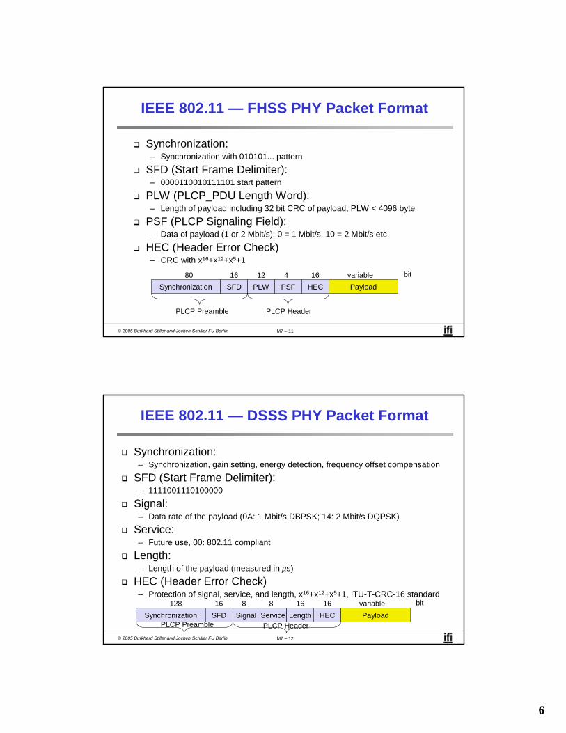
IEEE 802.11 — FHSS PHY Packet Format
Synchronization SFD PLW PSF HEC Payload
PLCP Preamble PLCP Header
80 16 12 4 16 variable bit
Synchronization:– Synchronization with 010101... pattern
SFD (Start Frame Delimiter):– 0000110010111101 start pattern
PLW (PLCP_PDU Length Word):– Length of payload including 32 bit CRC of payload, PLW < 4096 byte
PSF (PLCP Signaling Field):– Data of payload (1 or 2 Mbit/s): 0 = 1 Mbit/s, 10 = 2 Mbit/s etc.
HEC (Header Error Check)– CRC with x16+x12+x5+1
© 2005 Burkhard Stiller and Jochen Schiller FU Berlin M7 – 12
IEEE 802.11 — DSSS PHY Packet Format
Synchronization SFD Signal Service HEC PayloadPLCP Preamble PLCP Header
128 16 8 8 16 variable bit
Length16
Synchronization:– Synchronization, gain setting, energy detection, frequency offset compensation
SFD (Start Frame Delimiter):– 1111001110100000
Signal:– Data rate of the payload (0A: 1 Mbit/s DBPSK; 14: 2 Mbit/s DQPSK)
Service:– Future use, 00: 802.11 compliant
Length:– Length of the payload (measured in ms)
HEC (Header Error Check)– Protection of signal, service, and length, x16+x12+x5+1, ITU-T-CRC-16 standard
7
© 2005 Burkhard Stiller and Jochen Schiller FU Berlin M7 – 13
IEEE 802.11 — MAC Layer DFWMAC (1)
Traffic services (Roaming, Authentication, Energy Savings):– Asynchronous Data Service (mandatory):
• Exchange of data packets based on “best-effort”• Support of broadcast and multicast, however, no QoS support
– Time-Bounded Service (optional):• Implemented using PCF
3 Access methods:– DFWMAC-DCF CSMA/CA (mandatory) (Distributed Foundation Wireless MAC):
• Collision avoidance via randomized „back-off“ mechanism• Minimum distance between consecutive packets• ACK packet for acknowledgements (not for broadcasts)
– DFWMAC-DCF with RTS/CTS (optional):• Avoids hidden terminal problem
– DFWMAC- PCF (optional):• Access point polls terminals according to a list
DCF: Distributed Coordination FunctionPCF: Point Coordination Function
© 2005 Burkhard Stiller and Jochen Schiller FU Berlin M7 – 14
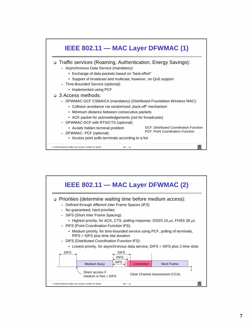
IEEE 802.11 — MAC Layer DFWMAC (2)
Priorities (determine waiting time before medium access):– Defined through different Inter Frame Spaces (IFS)– No guaranteed, hard priorities– SIFS (Short Inter Frame Spacing):
• Highest priority, for ACK, CTS, polling response: DSSS 10 ms, FHSS 28 ms– PIFS (Point Coordination Function IFS):
• Medium priority, for time-bounded service using PCF, polling of terminals, PIFS = SIFS plus time slot duration
– DIFS (Distributed Coordination Function IFS):• Lowest priority, for asynchronous data service, DIFS = SIFS plus 2 time slots
t
Medium Busy SIFSPIFSDIFSDIFS
Next FrameContention
Direct access if medium is free ≥ DIFS Clear Channel Assessment (CCA)

8
© 2005 Burkhard Stiller and Jochen Schiller FU Berlin M7 – 15
t
Medium Busy
DIFSDIFS
Next Frame
Contention Window(randomized back-offmechanism)
IEEE 802.11 — CSMA/CA Access Method (1)
– Station ready to send starts sensing the medium (Carrier Sense based on CCA, Clear Channel Assessment)
– If the medium is free for the duration of an Inter-Frame Space (IFS), the station can start sending (IFS depends on service type)
– If the medium is busy, the station has to wait for a free IFS, then the station must wait additionally a random back-off time (collision avoidance, multiple of slot-time)
– If another station occupies the medium during the back-off time of the station, the back-off timer stops (fairness)
Slot TimeDirect Access if medium is free ≥ DIFS
© 2005 Burkhard Stiller and Jochen Schiller FU Berlin M7 – 16
IEEE 802.11 — Competing Stations/Simple
t
busy
boe
Station1
Station2
Station3
Station4
Station5
Packet arrival at MAC
DIFSboe
boe
boe
busy
Elapsed back-off time
bor Residual back-off time
Busy Medium not idle (frame, ack etc.)
bor
bor
DIFS
boe
boe
boe bor
DIFS
busy
busy
DIFSboe busy
boe
boe
bor
bor

9
© 2005 Burkhard Stiller and Jochen Schiller FU Berlin M7 – 17
IEEE 802.11 — CSMA/CA Access Method (2)
Sending unicast packets:– Station has to wait for DIFS before sending data– Receivers acknowledge at once (after waiting for SIFS), if the packet was
received correctly (CRC)– Automatic retransmission of data packets in case of transmission errors
t
SIFS
DIFS
Data
ACK
Waiting Time
Otherstations
Receiver
Sender Data
DIFS
Contention
© 2005 Burkhard Stiller and Jochen Schiller FU Berlin M7 – 18
IEEE 802.11 — DFWMAC including RTS/CTS
Sending unicast packets:– Station can send RTS with reservation parameter after waiting for DIFS (reservation
determines amount of time the data packet needs the medium) – Acknowledgement via CTS after SIFS by receiver (if ready to receive)– Sender can now send data at once, acknowledgement via ACK– Other stations store medium reservations distributed via RTS and CTS
t
SIFS
DIFS
Data
ACK
Defer Access
Otherstations
Receiver
Sender Data
DIFS
Contention
RTS
CTSSIFS SIFS
NAV (RTS)NAV (CTS)
NAV: Net Allocation Vector (includes send duration planned and ACK for this transmission)

10
© 2005 Burkhard Stiller and Jochen Schiller FU Berlin M7 – 19
Fragmentation
t
SIFS
DIFS
Data
ACK1
Otherstations
Receiver
Sender frag1
DIFS
Contention
RTS
CTSSIFS SIFS
NAV (RTS)NAV (CTS)
NAV (frag1)NAV (ACK1)
SIFSACK2
frag2
SIFS
Minimization of error rates (transparent to users):– Erroneous frames in wireless networks with a larger probability than in wired
networks due to larger bit error rate– Shorten frames!– Sender reserves after DIFS by RTS medium (only first fragment length plus ACK)– Receiver acks with CTS including first fragment length plus ACK– New fragment frag1 contains a fragment length: ACK1, frag2, and ACK2!
© 2005 Burkhard Stiller and Jochen Schiller FU Berlin M7 – 20
DFWMAC-PCF (1)
PIFS
Stations‘NAV
WirelessStations
Point Coordinator
D1
U1
SIFS
NAV
SIFSD2
U2
SIFS
SIFS
SuperFramet0
Medium Busy
t1
Point Co-ordination Function (PCF):– Time-based service required for some applications– Access point required to determine access and polling of stations– Only applicable in infrastructure mode, ad-hoc not possible -> no QoS!– Contention-free period shown:
• Starting point moved to t1 due to busy medium at t0.• Wait for PCF Inter-frame Spacing (PIFS): PIFS < DIFS

11
© 2005 Burkhard Stiller and Jochen Schiller FU Berlin M7 – 21
DFWMAC-PCF (2)
tStations‘NAV
WirelessStations
Point Coordinator
D3
NAV
PIFSD4
U4
SIFS
SIFSCFend
ContentionPeriod
Contention Free Period
t2 t3 t4
(Con’t)– Contention-free and contention period shown:– Station D3 does not have any reply in queue, waiting PIFS– PC frees contention-free period by CFend signal– Early release of super-frame, contention period moves from t3 to t2
© 2005 Burkhard Stiller and Jochen Schiller FU Berlin M7 – 22
IEEE 802.11 — Frame Format
Types:– Control frames, management frames, data frames
Sequence numbers:– Important against duplicated frames due to lost ACKs
Addresses:– Receiver, transmitter (physical), BSS identifier, sender (logical)
Miscellaneous:– Sending time, checksum, frame control, data
FrameControl
Duration/ID
Address1
Address2
Address3
SequenceControl
Address4 Data CRC
2 2 6 6 6 62 40-2312Byte
ProtocolVersion Type Subtype To
DSMoreFrag Retry Power
MgmtMoreData WEP
2 2 4 1FromDS
1
Order
bit 1 1 1 1 1 1

12
© 2005 Burkhard Stiller and Jochen Schiller FU Berlin M7 – 23
IEEE 802-11 — MAC Address Format
Scenario to DS fromDS
Address 1 Address2
Address 3 Address 4
Ad-hoc network 0 0 DA SA BSSID -Infrastructurenetwork, from AP
0 1 DA BSSID SA -
Infrastructurenetwork, to AP
1 0 BSSID SA DA -
Infrastructurenetwork, within DS
1 1 RA TA DA SA
DS: Distribution SystemAP: Access PointDA: Destination AddressSA: Source AddressBSSID: Basic Service Set IdentifierRA: Receiver AddressTA: Transmitter Address
Address 1: AP or STAAddress 2: Physically sending STA,
receives MAC ACKAddress 3: Logically sending STA, BSSAddress 4: similar (optional)
© 2005 Burkhard Stiller and Jochen Schiller FU Berlin M7 – 24
Special Frames: ACK, RTS, CTS
Acknowledgement:
Request To Send:
Clear To Send:
FrameControl Duration Receiver
AddressTransmitter
Address CRC
2 2 6 6 4Byte
FrameControl Duration Receiver
Address CRC
2 2 6 4Byte
FrameControl Duration Receiver
Address CRC
2 2 6 4Byte
ACK
RTS
CTS
13
© 2005 Burkhard Stiller and Jochen Schiller FU Berlin M7 – 25
IEEE 802.11 — MAC Management
Synchronization:– Try to find a LAN, try to stay within a LAN– Timer
Power management:– Sleep-mode without missing a message– Periodic sleep, frame buffering, traffic measurements
Association/Re-association (Roaming):– Integration into a LAN– Roaming, i.e. change networks by changing access points – Scanning, i.e. active search for a network
MIB - Management Information Base:– Managing, read, write
© 2005 Burkhard Stiller and Jochen Schiller FU Berlin M7 – 26
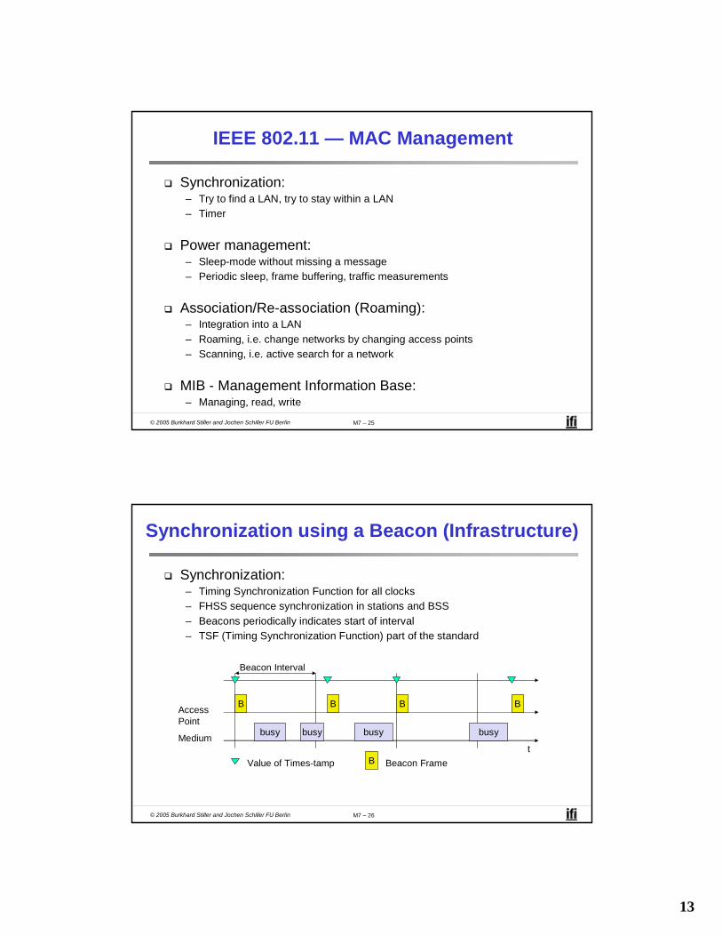
Synchronization using a Beacon (Infrastructure)
Beacon Interval
tMedium
AccessPoint
busy
B
busy busy busy
B B B
Value of Times-tamp B Beacon Frame
Synchronization:– Timing Synchronization Function for all clocks– FHSS sequence synchronization in stations and BSS– Beacons periodically indicates start of interval– TSF (Timing Synchronization Function) part of the standard
14
© 2005 Burkhard Stiller and Jochen Schiller FU Berlin M7 – 27
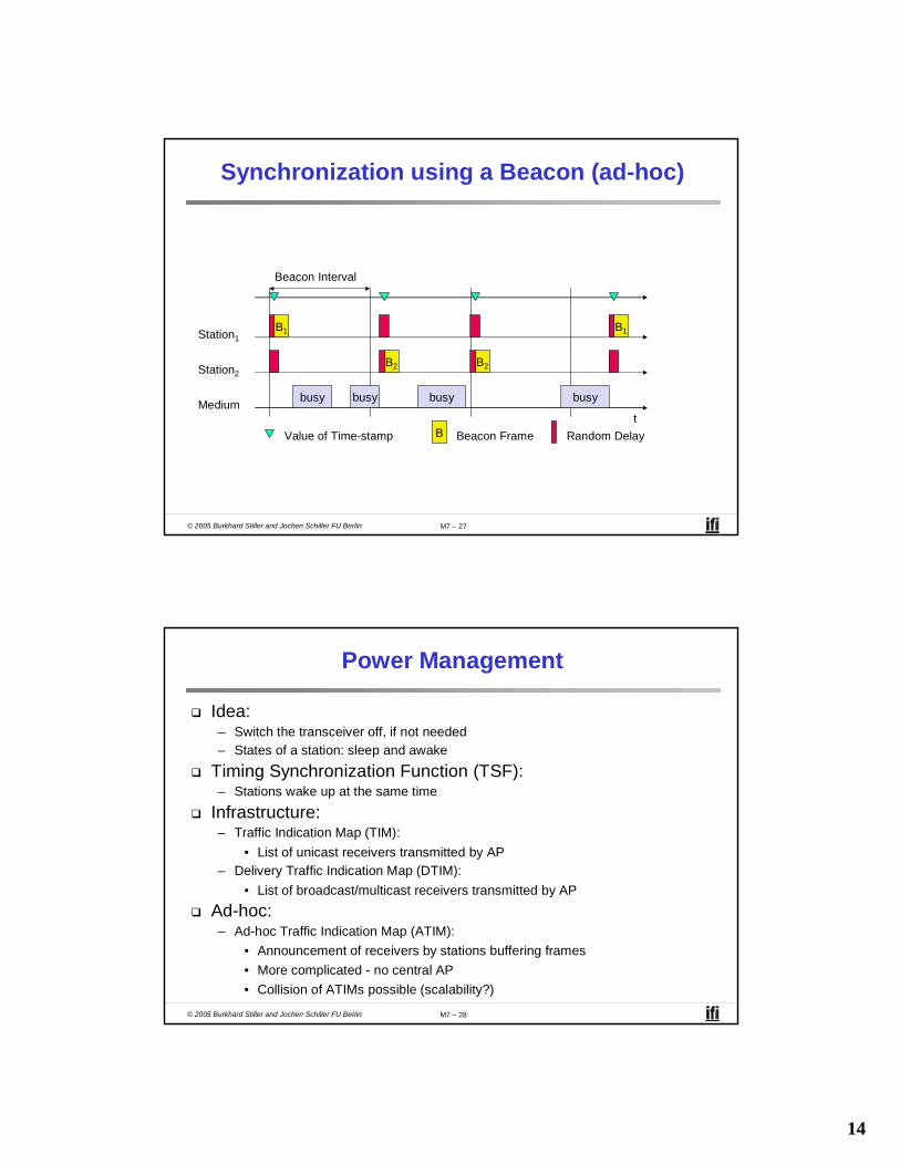
Synchronization using a Beacon (ad-hoc)
tMedium
Station1
busy
B1
Beacon Interval
busy busy busy
B1
Value of Time-stamp B Beacon Frame
Station2B2 B2
Random Delay
© 2005 Burkhard Stiller and Jochen Schiller FU Berlin M7 – 28
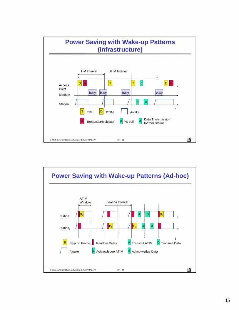
Power Management
Idea:– Switch the transceiver off, if not needed– States of a station: sleep and awake
Timing Synchronization Function (TSF):– Stations wake up at the same time
Infrastructure:– Traffic Indication Map (TIM):
• List of unicast receivers transmitted by AP– Delivery Traffic Indication Map (DTIM):
• List of broadcast/multicast receivers transmitted by APAd-hoc:– Ad-hoc Traffic Indication Map (ATIM):
• Announcement of receivers by stations buffering frames• More complicated - no central AP• Collision of ATIMs possible (scalability?)
15
© 2005 Burkhard Stiller and Jochen Schiller FU Berlin M7 – 29
Power Saving with Wake-up Patterns (Infrastructure)
TIM Interval
t
Medium
AccessPoint
busy
D
busy busy busy
T T D
T TIM D DTIM
DTIM Interval
BB
B Broadcast/Multicast
Station
Awake
p PS poll
p
d
d
d Data Transmissionto/from Station
© 2005 Burkhard Stiller and Jochen Schiller FU Berlin M7 – 30
Power Saving with Wake-up Patterns (Ad-hoc)
Awake
A Transmit ATIM D Transmit Datat
Station1B1 B1
B Beacon Frame
Station2B2 B2
Random Delay
A
a
D
d
ATIMWindow Beacon Interval
a Acknowledge ATIM d Acknowledge Data
16
© 2005 Burkhard Stiller and Jochen Schiller FU Berlin M7 – 31
IEEE 802.11 — Roaming
No or bad connection? Then perform:Scanning:– Scan the environment, i.e., listen into the medium for beacon signals or send
probes into the medium and wait for an answer
Re-association Request:– Station sends a request to one or several AP(s)
Re-association Response:– Success: AP has answered, station can now participate– Failure: continue scanning
AP accepts Re-association Request– Signal the new station to the distribution system– The distribution system updates its data base (i.e., location information)– Typically, the distribution system now informs the old AP so it can release
resources
© 2005 Burkhard Stiller and Jochen Schiller FU Berlin M7 – 32
WLAN: IEEE 802.11b
Data rate:– 1, 2, 5.5, 11 Mbit/s, depending on SNR – User data rate max. approx. 6 Mbit/s
Transmission range:– 300 m outdoor, 30 m indoor– Max. data rate ~10 m indoor
Frequency:– Free 2.4 GHz ISM-band
Security:– Limited, WEP insecure, BSSID
Cost:– 100 € per adapter, 250 € per base
station, dropping
Availability:– Many products, many vendors
Connection set-up time:– Connectionless/always on
Quality-of-Service:– Typically best effort, no guarantees
(unless polling is used, limited support in products)
Manageability:– Limited (no automated key distribution,
sym. Encryption)Special advantages/drawbacks:
– Advantage: many installed systems, lot of experience, available worldwide, free ISM-band, many vendors, integrated in laptops, simple system
– Drawback: heavy interference on ISM-band, no service guarantees, slow relative speed only

17
© 2005 Burkhard Stiller and Jochen Schiller FU Berlin M7 – 33
IEEE 802.11b — PHY Frame Formats
Synchronization SFD Signal Service HEC Payload
PLCP Preamble PLCP Header
128 16 8 8 16 variable bit
Length16
192 µs at 1 Mbit/s DBPSK 1, 2, 5.5 or 11 Mbit/s
Short Synchronization SFD Signal Service HEC Payload
PLCP Preamble(1 Mbit/s, DBPSK)
PLCP Header(2 Mbit/s, DQPSK)
56 16 8 8 16 variable bit
Length16
96 µs 2, 5.5 or 11 Mbit/s
Long PLCP (Physical Layer Convergence Protocol) PPDU Format
Short PLCP PPDU Format (optional)
DBPSK: Differential Binary PSK, DQPSK: Differential Quadrature PSK
© 2005 Burkhard Stiller and Jochen Schiller FU Berlin M7 – 34
Channel Selection (Non-overlapping)
2400[MHz]
2412 2483.52442 2472
Channel 1 Channel 7 Channel 13
Europe (ETSI)
US (FCC)/Canada (IC)
2400[MHz]
2412 2483.52437 2462
Channel 1 Channel 6 Channel 11
22 MHz
22 MHz
18
© 2005 Burkhard Stiller and Jochen Schiller FU Berlin M7 – 35
WLAN: IEEE 802.11a
Data rates:– 6, 9, 12, 18, 24, 36, 48, 54 Mbit/s (SNR)– User throughput (1500 byte packets): 5.3 (6),
18 (24), 24 (36), 32 (54) – 6, 12, 24 Mbit/s mandatory
Transmission range:– 100m outdoor, 10m indoor
• E.g., 54 Mbit/s up to 5 m, 48 up to 12 m, 36 up to 25 m, 24 up to 30m, 18 up to 40 m, 12 up to 60 m
Frequency:– Free 5.15-5.25, 5.25-5.35, 5.725-5.825 GHz
Security:– Limited, WEP insecure, SSID
Cost:– 280€ adapter, 500€ base station
Availability:– Some products, some vendors
Connection set-up time:– Connectionless/always on
Quality-of-Service:– Typically best effort, no guarantees
(same as all IEEE 802.11 standards)Manageability:
– Limited (no automated key distribution, sym. Encryption)
Special advantages/drawbacks:– Advantage: fits into 802.x standards, free
ISM-band, available, simple system, uses
less crowded 5 GHz band
– Drawback: stronger shading due to higher
frequency, no QoS
© 2005 Burkhard Stiller and Jochen Schiller FU Berlin M7 – 36
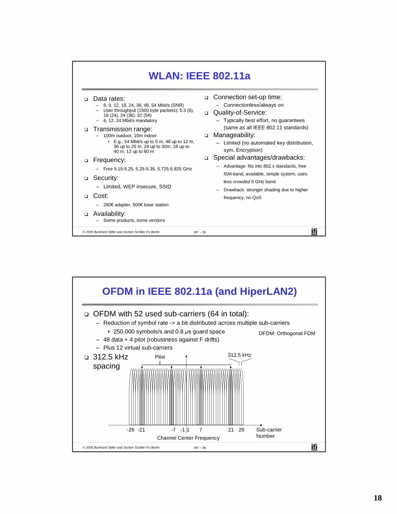
OFDM in IEEE 802.11a (and HiperLAN2)
OFDM with 52 used sub-carriers (64 in total):– Reduction of symbol rate -> a bit distributed across multiple sub-carriers
• 250.000 symbols/s and 0.8 ms guard space– 48 data + 4 pilot (robustness against F drifts)– Plus 12 virtual sub-carriers
312.5 kHz spacing
Sub-carrierNumber
1 7 21 26-26 -21 -7 -1Channel Center Frequency
312.5 kHzPilot
OFDM: Orthogonal FDM

19
© 2005 Burkhard Stiller and Jochen Schiller FU Berlin M7 – 37
Operating Channels for IEEE 802.11a/US U-NII
5150 [MHz]5180 53505200
36 44
16.6 MHz
Center frequency = 5000 + 5*channel number [MHz]
Channel40 48 52 56 60 64
149 153 157 161
5220 5240 5260 5280 5300 5320
5725 [MHz]5745 58255765
16.6 MHz
Channel
5785 5805
© 2005 Burkhard Stiller and Jochen Schiller FU Berlin M7 – 38
IEEE 802.11a — PHY Frame Format
Rate Service Payload
variable bit
6 Mbit/s
PLCP Preamble Signal Data
symbol12
16 ms
1 variable
Reserved Length TailParity Tail Pad
616611214 variable
6, 9, 12, 18, 24, 36, 48, 54 Mbit/s
PLCP Header

20
© 2005 Burkhard Stiller and Jochen Schiller FU Berlin M7 – 39
WLAN: IEEE 802.11 — Future Developments (12/2003)
802.11d: Regulatory Domain Update – completed802.11e: MAC Enhancements – QoS – completed– Enhance the current 802.11 MAC to expand support for applications with Quality
of Service requirements, and in the capabilities and efficiency of the protocol. 802.11f: Inter-Access Point Protocol – ongoing– Establish an Inter-Access Point Protocol for data exchange via the distribution
system.802.11g: Data Rates > 20 Mbit/s at 2.4 GHz; 54 Mbit/s, OFDM –completed802.11h: Spectrum Managed 802.11a (DCS, TPC) – ongoing 802.11i: Enhanced Security Mechanisms – ongoing– Enhance the current 802.11 MAC to provide improvements in security.
Study Groups:– 5 GHz (harmonization ETSI/IEEE) – closed – Radio Resource Measurements – started– High Throughput – ongoing
OFDM: Orthogonal FDM
© 2005 Burkhard Stiller and Jochen Schiller FU Berlin M7 – 40
ETSI — HIPERLAN
ETSI standard:– European standard, cf. GSM, DECT, ...– Enhancement of local networks and inter-working with fixed networks– Integration of time-sensitive services from the early beginning
HIPERLAN family:– One standard cannot satisfy all requirements
• Range, bandwidth, QoS support• Commercial constraints
– HIPERLAN 1 standardized since 1996 – no products up to now!
Physical Layer
Channel AccessControl Layer
Medium Access Control Layer
Physical Layer
Data Link Layer
HIPERLAN layers OSI layers
Network Layer
Higher Layers
Physical Layer
Medium AccessControl Layer
Logical Link Control Layer
IEEE 802.x layers
21
© 2005 Burkhard Stiller and Jochen Schiller FU Berlin M7 – 41
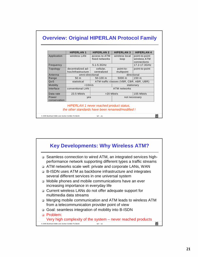
Overview: Original HIPERLAN Protocol Family
HIPERLAN 1 HIPERLAN 2 HIPERLAN 3 HIPERLAN 4Application wireless LAN access to ATM
fixed networkswireless local
looppoint-to-pointwireless ATMconnections
Frequency 5.1-5.3GHz 17.2-17.3GHzTopology decentralized ad-
hoc/infrastructurecellular,
centralizedpoint-to-
multipointpoint-to-point
Antenna omni-directional directionalRange 50 m 50-100 m 5000 m 150 mQoS statistical ATM traffic classes (VBR, CBR, ABR, UBR)Mobility <10m/s stationaryInterface conventional LAN ATM networks
Data rate 23.5 Mbit/s >20 Mbit/s 155 Mbit/sPowerconservation
yes not necessary
HIPERLAN 1 never reached product status, the other standards have been renamed/modified !
© 2005 Burkhard Stiller and Jochen Schiller FU Berlin M7 – 42
Key Developments: Why Wireless ATM?
Seamless connection to wired ATM, an integrated services high-performance network supporting different types a traffic streamsATM networks scale well: private and corporate LANs, WAN B-ISDN uses ATM as backbone infrastructure and integrates several different services in one universal system Mobile phones and mobile communications have an ever increasing importance in everyday lifeCurrent wireless LANs do not offer adequate support for multimedia data streamsMerging mobile communication and ATM leads to wireless ATM from a telecommunication provider point of viewGoal: seamless integration of mobility into B-ISDNProblem: Very high complexity of the system – never reached products

22
© 2005 Burkhard Stiller and Jochen Schiller FU Berlin M7 – 43
ATM — Basic Principles
– Favored by the telecommunication industry for advanced high-performance networks, e.g., B-ISDN, as transport mechanism
– Statistical (asynchronous, on demand) TDM (ATDM, STDM)– Cell header determines the connection the user data belongs to– Mixing of different cell-rates is possible:
• Different bit-rates, constant or variable, feasible– Interesting for data sources with varying bit-rate:
• E.g., guaranteed minimum bit-rate• Additionally bursty traffic if allowed by the network
ATM cell: 5 48 Byte
Connection Identifier, Checksum
Cell Header User Data
© 2005 Burkhard Stiller and Jochen Schiller FU Berlin M7 – 44
ATM Forum Wireless ATM Working Group
ATM Forum founded Wireless ATM Working Group 06/1996Task: – Development of specifications to enable the use of ATM technology also for
wireless networks with a large coverage of current network scenarios (private and public, local and global)
– Compatibility to existing ATM Forum standards important
It should be possible to easily upgrade existing ATM networks with mobility functions and radio access Two sub-groups of work items:
Mobile ATM Protocol Extensions:– Hand-over signaling– Location management– Mobile routing– Traffic and QoS Control– Network management
Radio Access Layer (RAL) Protocols:– Radio access layer– Wireless media access control– Wireless data link control– Radio resource control– Hand-over issues
23
© 2005 Burkhard Stiller and Jochen Schiller FU Berlin M7 – 45
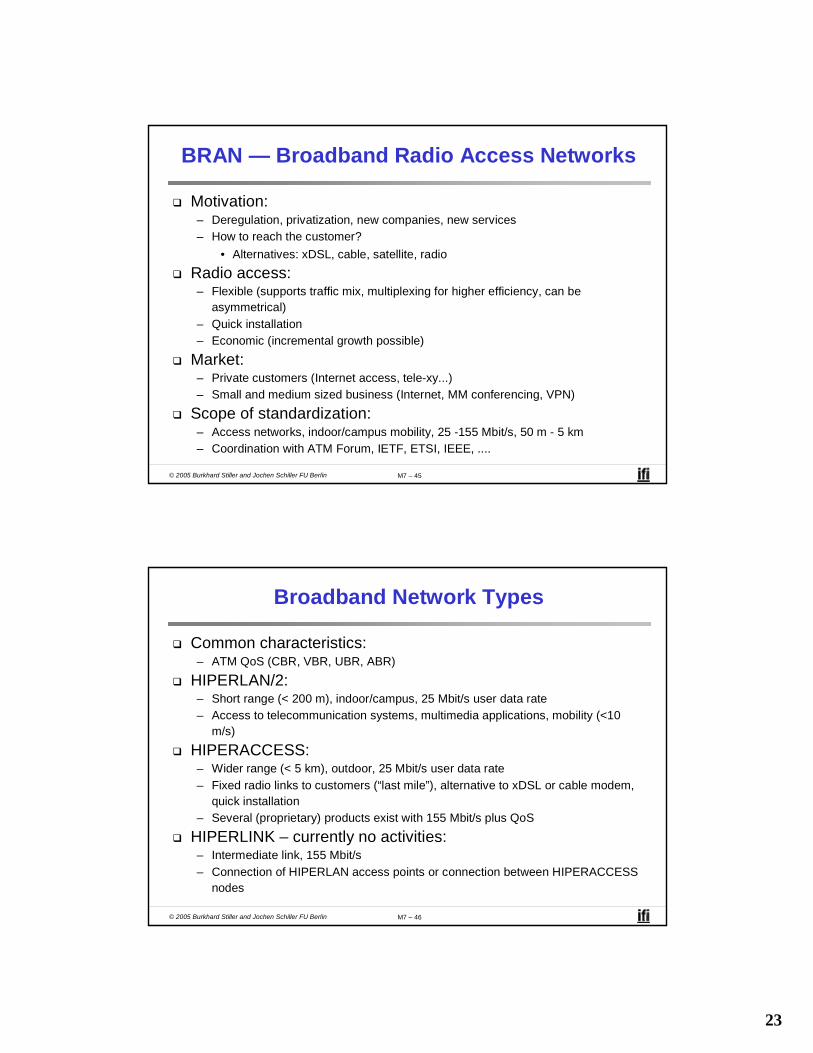
BRAN — Broadband Radio Access Networks
Motivation:– Deregulation, privatization, new companies, new services– How to reach the customer?
• Alternatives: xDSL, cable, satellite, radio
Radio access:– Flexible (supports traffic mix, multiplexing for higher efficiency, can be
asymmetrical)– Quick installation– Economic (incremental growth possible)
Market:– Private customers (Internet access, tele-xy...)– Small and medium sized business (Internet, MM conferencing, VPN)
Scope of standardization:– Access networks, indoor/campus mobility, 25 -155 Mbit/s, 50 m - 5 km– Coordination with ATM Forum, IETF, ETSI, IEEE, ....
© 2005 Burkhard Stiller and Jochen Schiller FU Berlin M7 – 46
Broadband Network Types
Common characteristics:– ATM QoS (CBR, VBR, UBR, ABR)
HIPERLAN/2:– Short range (< 200 m), indoor/campus, 25 Mbit/s user data rate– Access to telecommunication systems, multimedia applications, mobility (<10
m/s)
HIPERACCESS:– Wider range (< 5 km), outdoor, 25 Mbit/s user data rate– Fixed radio links to customers (“last mile”), alternative to xDSL or cable modem,
quick installation– Several (proprietary) products exist with 155 Mbit/s plus QoS
HIPERLINK – currently no activities:– Intermediate link, 155 Mbit/s– Connection of HIPERLAN access points or connection between HIPERACCESS
nodes

24
© 2005 Burkhard Stiller and Jochen Schiller FU Berlin M7 – 47
BRAN and Legacy Networks
Independence:– BRAN as access network independent from the fixed network– Inter-working of TCP/IP and ATM under study
Layered model:– Network Convergence Sub-layer as superset of all requirements for IP and ATM
Core NetworkATM
Core NetworkIP
Network Convergence Sublayer
BRAN Data Link Control
BRAN PHY-1 BRAN PHY-2 ...
Coordination:– IETF (TCP/IP)– ATM forum (ATM)– ETSI (UMTS)– CEPT, ITU-R, ...
(radio frequencies)
© 2005 Burkhard Stiller and Jochen Schiller FU Berlin M7 – 48
HiperLAN2
Official name: BRAN HIPERLAN Type 2:– H/2, HIPERLAN/2 also used
Characteristics:– High data rates for users: 54 Mbit/s at 5 GHz– More efficient than 802.11a– Connection oriented– QoS support– Dynamic frequency selection– Security support
• Strong encryption/authentication– Mobility support– Network and application independent
• Convergence layers for Ethernet, IEEE 1394, ATM, 3G– Power save modes – Plug and Play
Http://www.hiperlan2.com

25
© 2005 Burkhard Stiller and Jochen Schiller FU Berlin M7 – 49
Ad-hoc Networking Today
Almost no (large) ad-hoc systems exist
Playing with multi-hop on WLAN:– Mobihoc, Mobicom
NS-2 plots get boring in the long run:– Specific MAC layer problem analysis
So why is nobody doing the real thing?– Bulky– Short standalone operating times– Hard to manage multitude of devices– Limitations on features and communication front-ends– Often only point to point– SDK’s only for selected “customers”
© 2005 Burkhard Stiller and Jochen Schiller FU Berlin M7 – 50
Bluetooth
Idea:– Universal radio interface for ad-hoc wireless connectivity– Interconnecting computer and peripherals, handheld devices, PDAs, cell phones
• Replacement of IrDA– Embedded in other devices, goal: 5 €/device (2002: 50 €/USB Bluetooth)– Short range (10 m), low power consumption, license-free 2.45 GHz ISM– Voice and data transmission, approx. 1 Mbit/s gross data rate
One of the first modules (Ericsson).

26
© 2005 Burkhard Stiller and Jochen Schiller FU Berlin M7 – 51
Bluetooth
History:– 1994: Ericsson (Mattison/Haartsen), “MC-link” project– Renaming of the project:
• Bluetooth according to Harald “Blåtand” Gormsen [son of Gorm], King of Denmark in the 10th century
– 1998: Foundation of Bluetooth SIG, http://www.bluetooth.org– 1999: Erection of a rune stone at Ericsson/Lund ;-)– 2001: First consumer products for mass market, spec. version 1.1 released
Special Interest Group:– Original founding members: Ericsson, Intel, IBM, Nokia, Toshiba– Added promoters: 3Com, Agere (was: Lucent), Microsoft, Motorola– More than 2500 members– Common specification and certification of products
(was: )
© 2005 Burkhard Stiller and Jochen Schiller FU Berlin M7 – 52
Ericsson and the Real Rune Stone
Located in Jelling, Denmark,erected by King Harald “Blåtand”in memory of his parents.The stone has three sides – one sideshowing a picture of Christ.
This could be the “original” colors of the stone.Inscription:“auk tani karthi kristna” (and made the Danes Christians)
Inscription:"Harald king executes these sepulchral monuments after Gorm, his father and Thyra, his mother. The Harald who won the whole of Denmark and Norway and turned the Danes to Christianity."
Btw: Blåtand means “of dark complexion”(not having a blue tooth…)
27
© 2005 Burkhard Stiller and Jochen Schiller FU Berlin M7 – 53
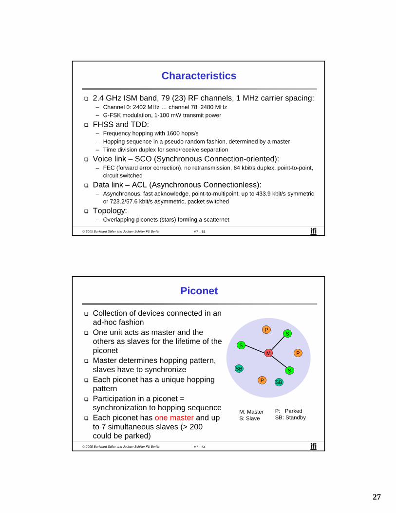
Characteristics
2.4 GHz ISM band, 79 (23) RF channels, 1 MHz carrier spacing:– Channel 0: 2402 MHz … channel 78: 2480 MHz– G-FSK modulation, 1-100 mW transmit power
FHSS and TDD:– Frequency hopping with 1600 hops/s– Hopping sequence in a pseudo random fashion, determined by a master– Time division duplex for send/receive separation
Voice link – SCO (Synchronous Connection-oriented):– FEC (forward error correction), no retransmission, 64 kbit/s duplex, point-to-point,
circuit switched
Data link – ACL (Asynchronous Connectionless):– Asynchronous, fast acknowledge, point-to-multipoint, up to 433.9 kbit/s symmetric
or 723.2/57.6 kbit/s asymmetric, packet switched
Topology:– Overlapping piconets (stars) forming a scatternet
© 2005 Burkhard Stiller and Jochen Schiller FU Berlin M7 – 54
Piconet
Collection of devices connected in an ad-hoc fashionOne unit acts as master and the others as slaves for the lifetime of the piconetMaster determines hopping pattern, slaves have to synchronizeEach piconet has a unique hopping patternParticipation in a piconet = synchronization to hopping sequenceEach piconet has one master and up to 7 simultaneous slaves (> 200 could be parked)
M: MasterS: Slave
P: ParkedSB: Standby
MS
P
SB
S
S
P
P
SB

28
© 2005 Burkhard Stiller and Jochen Schiller FU Berlin M7 – 55
Forming a Piconet
All devices in a piconet hop together:– Master gives slaves its clock and device ID:
• Hopping pattern: determined by device ID (48 bit, unique worldwide)• Phase in hopping pattern determined by clock• All members utilize the same 1 MHz channel
Addressing for active members:– Active Member Address (AMA, 3 bit)– Parked Member Address (PMA, 8 bit)
SBSB
SB
SB
SB
SB
SB
SB
SB
MS
P
SB
S
S
P
P
SB
M: MasterS: Slave
P: ParkedSB: Standby
© 2005 Burkhard Stiller and Jochen Schiller FU Berlin M7 – 56
Scatternet
Linking of multiple co-located piconets through the sharing of common master or slave devices:– Devices can be slave in one piconet and master of another
Communication between piconets:– Devices jumping back and forth between the piconets
M: MasterS: SlaveP: ParkedSB: Standby
M
S
P
SB
S
S
P
P
SB
M
S
S
P
SB
Piconets(each with a capacity of < 1 Mbit/s)

29
© 2005 Burkhard Stiller and Jochen Schiller FU Berlin M7 – 57
Bluetooth Protocol Stack
Radio
Baseband
Link Manager
Control
Host Controller InterfaceLogical Link Control and Adaptation Protocol (L2CAP)Audio
TCS BIN SDP
OBEX
vCal/vCard
IP
NW apps.
TCP/UDP
PPP/BNEP
RFCOMM (serial line interface)
AT modemcommands
Telephony apps.Audio apps. Mgt. apps.
AT: Attention sequenceOBEX: Object exchangeTCS BIN: Telephony control protocol specification – binaryBNEP: Bluetooth network encapsulation protocol
SDP: Service discovery protocolRFCOMM: Radio frequency comm.
On module
On host
© 2005 Burkhard Stiller and Jochen Schiller FU Berlin M7 – 58
S
Frequency Selection During Data Transmission
fk
625 µs
fk+1 fk+2 fk+3 fk+4
fk+3 fk+4fk
fk
fk+5
fk+5
fk+1 fk+6
fk+6
fk+6
MM M M
M
M M
M M
t
t
t
S S
S S
S

30
© 2005 Burkhard Stiller and Jochen Schiller FU Berlin M7 – 59
Baseband
Piconet/channel definitionLow-level packet definition:– Access code:
• Channel, device access, e.g., derived from master– Packet header:
• 1/3-FEC, active member address (broadcast + 7 slaves), link type, alternating bit ARQ/SEQ, checksum
Access Code Packet Header Payload68(72) 54 0-2745 bit
AM Address Type Flow ARQN SEQN HEC3 4 1 1 1 8 bit
Preamble Sync. (Trailer)
4 64 (4)
(Typo in thestandard!)
© 2005 Burkhard Stiller and Jochen Schiller FU Berlin M7 – 60
Synchronous Connection-oriented Payload Types
Payload (30)
Audio (30)
Audio (10)
Audio (10)
HV3
HV2
HV1
DV
FEC (20)
Audio (20) FEC (10)
Header (1) Payload (0-9) 2/3 FEC CRC (2)
(Byte)HV: High-quality VideoDV: Data-Voice combined
Types
31
© 2005 Burkhard Stiller and Jochen Schiller FU Berlin M7 – 61
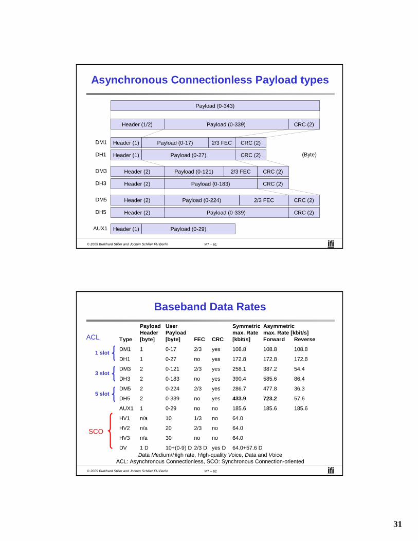
Asynchronous Connectionless Payload types
Payload (0-343)
Header (1/2) Payload (0-339) CRC (2)
Header (1) Payload (0-17) 2/3 FEC
Header (1) Payload (0-27)
Header (2) Payload (0-121) 2/3 FEC
Header (2) Payload (0-183)
Header (2) Payload (0-224) 2/3 FEC
Header (2) Payload (0-339)DH5
DM5
DH3
DM3
DH1
DM1
Header (1) Payload (0-29)AUX1
CRC (2)
CRC (2)
CRC (2)
CRC (2)
CRC (2)
CRC (2)
(Byte)
© 2005 Burkhard Stiller and Jochen Schiller FU Berlin M7 – 62
Baseband Data RatesPayload User Symmetric AsymmetricHeader Payload max. Rate max. Rate [kbit/s]
Type [byte] [byte] FEC CRC [kbit/s] Forward Reverse
DM1 1 0-17 2/3 yes 108.8 108.8 108.8
DH1 1 0-27 no yes 172.8 172.8 172.8
DM3 2 0-121 2/3 yes 258.1 387.2 54.4
DH3 2 0-183 no yes 390.4 585.6 86.4
DM5 2 0-224 2/3 yes 286.7 477.8 36.3
DH5 2 0-339 no yes 433.9 723.2 57.6
AUX1 1 0-29 no no 185.6 185.6 185.6
HV1 n/a 10 1/3 no 64.0
HV2 n/a 20 2/3 no 64.0
HV3 n/a 30 no no 64.0
DV 1 D 10+(0-9) D 2/3 D yes D 64.0+57.6 D
ACL
1 slot
3 slot
5 slot
SCO
Data Medium/High rate, High-quality Voice, Data and VoiceACL: Asynchronous Connectionless, SCO: Synchronous Connection-oriented

32
© 2005 Burkhard Stiller and Jochen Schiller FU Berlin M7 – 63
Baseband Link Types
Polling-based TDD packet transmission:– 625 µs slots, master polls slaves
SCO (Synchronous Connection-oriented) – Voice: – Periodic single slot packet assignment, 64 kbit/s full-duplex, point-to-point
ACL (Asynchronous Connectionless) – Data: – Variable packet size (1,3,5 slots), asymmetric bandwidth, point-to-multipoint
MASTER
SLAVE 1
SLAVE 2
f6f0
f1 f7
f12
f13 f19
f18
SCO SCO SCO SCOACL
f5 f21
f4 f20
ACLACLf8
f9
f17
f14
ACL
© 2005 Burkhard Stiller and Jochen Schiller FU Berlin M7 – 64
Robustness
Slow frequency hopping with hopping patterns determined by a master:– Protection from interference on certain frequencies– Separation from other piconets (FH-CDMA)
Retransmission:– ACL only, very fast
Forward Error Correction:– SCO and ACL
MASTER
SLAVE 1
SLAVE 2
A C C HF
G G
B D E
NAK ACK

33
© 2005 Burkhard Stiller and Jochen Schiller FU Berlin M7 – 65
Baseband States of a Bluetooth Device
standby
inquiry page
connectedAMA
transmitAMA
parkPMA
holdAMA
sniffAMA
unconnected
connecting
active
low power
Standby: do nothingInquire: search for other devicesPage: connect to a specific deviceConnected: participate in a piconet
detach
Park: release AMA, get PMA Sniff: listen periodically, not each slotHold: stop ACL, SCO still possible, possibly
participate in another piconet
© 2005 Burkhard Stiller and Jochen Schiller FU Berlin M7 – 66
Example: Power Consumption/CSR BlueCore2
Typical Average Current Consumption (1)VDD=1.8V Temperature = 20°CMode SCO connection HV3 (1s interval Sniff Mode) (Slave) 26.0 mASCO connection HV3 (1s interval Sniff Mode) (Master) 26.0 mASCO connection HV1 (Slave) 53.0 mASCO connection HV1 (Master) 53.0 mAACL data transfer 115.2kbps UART (Master) 15.5 mAACL data transfer 720kbps USB (Slave) 53.0 mAACL data transfer 720kbps USB (Master) 53.0 mAACL connection, Sniff Mode 40 ms interval, 38.4 kbit/s UART 4.0 mAACL connection, Sniff Mode 1.28 s interval, 38.4 kbit/s UART 0.5 mAParked Slave, 1.28s beacon interval, 38.4 kbit/s UART 0.6 mAStandby Mode (Connected to host, no RF activity) 47.0 µADeep Sleep Mode (2) 20.0 µANotes:(1) Current consumption is the sum of both BC212015A and the flash.(2) Current consumption is for the BC212015A device only.(More: http://www.csr.com )

34
© 2005 Burkhard Stiller and Jochen Schiller FU Berlin M7 – 67
Example: Bluetooth/USB Adapter (2003: 30 €)
© 2005 Burkhard Stiller and Jochen Schiller FU Berlin M7 – 68
L2CAP — Logical Link Layer Control and Adaptation Layer Protocol
Simple data link protocol on top of baseband– Applied to ACL only
Connection oriented, connectionless, and signaling channels
Protocol multiplexing:– RFCOMM, SDP, telephony control
Segmentation and reassembly:– Up to 64kbyte user data, 16 bit CRC used from baseband
QoS flow specification per channel:– Follows RFC 1363, specifies delay, jitter, bursts, bandwidth
Group abstraction:– Create/close group, add/remove member
L2CAP: Logical Link Control and Adaptation Protocol

35
© 2005 Burkhard Stiller and Jochen Schiller FU Berlin M7 – 69
L2CAP Logical Channels
Baseband
L2CAP
Baseband
L2CAP
Baseband
L2CAP
Slave SlaveMaster
ACL
2 d 1 d d 1 1 d 21
Signaling Connectionless Connection-oriented
d d d
2 CID: Channel Identifier, here example 2
© 2005 Burkhard Stiller and Jochen Schiller FU Berlin M7 – 70
L2CAP Packet Formats
Length2 Byte
CID=22
PSM≥2
Payload0-65533
Length2 Byte
CID2
Payload0-65535
Length2 Byte
CID=12
One or more commands
Connectionless PDU
Connection-oriented PDU
Signaling command PDU
Code ID Length Data1 1 2 ≥0PSM: Protocol/Service
Multiplexor

36
© 2005 Burkhard Stiller and Jochen Schiller FU Berlin M7 – 71
Security
E3
E2
Link key (128 bit)
Encryption key (128 bit)
Payload key
Key stream generator
Data DataCipher data
Authentication key generation(possibly permanent storage)
Encryption key generation(temporary storage)
PIN (1-16 byte)User input (initialization)
Pairing
Authentication
Encryption
Ciphering
E3
E2
Link key (128 bit)
Encryption key (128 bit)
Payload key
Key stream generator
PIN (1-16 byte)
Key, device address, time
© 2005 Burkhard Stiller and Jochen Schiller FU Berlin M7 – 72
SDP — Service Discovery Protocol
Inquiry/response protocol for discovering services:– Searching for and browsing services in radio proximity– Adapted to the highly dynamic environment– Can be complemented by others like SLP, Jini, Salutation, …– Defines discovery only, not the usage of services– Caching of discovered services– Gradual discovery
Service record format:– Information about services provided by attributes– Attributes are composed of an 16 bit ID (name) and a value– values may be derived from 128 bit Universally Unique Identifiers (UUID)

37
© 2005 Burkhard Stiller and Jochen Schiller FU Berlin M7 – 73
Additional Protocols to Support Legacy Protocols and Applications
RFCOMM:– Emulation of a serial port (supports a large base of legacy applications)– Allows multiple ports over a single physical channel
Telephony Control Protocol Specification (TCS):– Call control (setup, release)– Group management
OBEX:– Exchange of objects, IrDA replacement
WAP:– Interacting with applications on cellular phones
© 2005 Burkhard Stiller and Jochen Schiller FU Berlin M7 – 74
Profiles
Represent default solutions for a certain usage model:
– Vertical slice through the protocol stack– Basis for interoperability
Generic Access ProfileService Discovery Application ProfileCordless Telephony ProfileIntercom ProfileSerial Port ProfileHeadset ProfileDial-up Networking ProfileFax ProfileLAN Access ProfileGeneric Object Exchange ProfileObject Push ProfileFile Transfer ProfileSynchronization Profile
Additional ProfilesAdvanced Audio DistributionPANAudio Video Remote ControlBasic PrintingBasic ImagingExtended Service DiscoveryGeneric Audio Video DistributionHands FreeHardcopy Cable Replacement
Profiles
Pro
toco
ls
Applications

38
© 2005 Burkhard Stiller and Jochen Schiller FU Berlin M7 – 75
Avalanche Rescue through Sensors
Avalanche victims fatalities:0-15 min: 8% fatalities15-35 min: most victims suffocate35-90 min: 27% survive
with air pockets90 -130 min: suffocation even
with air pockets> 130 min: 3% survive
e.g. air channels
Today’s beacon technology very crude:Periodical pulses: the louder, the closer457 kHz, 0.1W 80 m range
time really matters!
© 2005 Burkhard Stiller and Jochen Schiller FU Berlin M7 – 76
Physical Activity Detection Network
Use multiple motion sensors for context awarenessIdea: Many sensors reveal „more context“ Architecture required to combine those sensors Map hierarchical topology to human body
P. Lukowicz et al. WearNET: A distributed multi-sensor system for context aware
wearables. Ubicomp 2002.

39
© 2005 Burkhard Stiller and Jochen Schiller FU Berlin M7 – 77
Hardware Requirements
Autonomous wireless communication and computing platform based on a Bluetooth radio module and a micro controller.
Requirements:– Small form factor, low component count– Standardized wireless interface– Flexible and cost effective deployment of large quantities of networking nodes
© 2005 Burkhard Stiller and Jochen Schiller FU Berlin M7 – 78
BTnode Hardware Details
Atmel ATmega 128l MCU 8-Bit RISC (max. 8 MHz ~8 MIPS)Real time clock128 kB Flash ROM 64 kB SRAM4 kB EEPROMGeneric sensor interfacesUART and I2C data interfacePower and frequency managementIntegrated PIFA antenna

40
© 2005 Burkhard Stiller and Jochen Schiller FU Berlin M7 – 79
Who is using BTnodes today?
Successful deployment of more than 200 units with more than 21 groups world-wide, second generation of BTnode is being worked at now:TIK, ETH Zurich
DSG, ETH Zurich
Computing Department, Lancaster University, UK
TecO, University of Karlsruhe, Germany
PLAY, Interactive Institute, Sweden
VTT, Finland
IFE Wearable Lab, ETH Zurich
NTTDoCoMo, Munich, Germany (Anthony Terlano)
Ptolemy Group, UC Berkeley, USA (Jörn Janneck)
Art of Technology, Zurich, Switzerland (Michael Scheffler)
DistLab, Diku, Copenhagen, Denmark (Philippe Bonnet)
…
© 2005 Burkhard Stiller and Jochen Schiller FU Berlin M7 – 80
WPAN: IEEE 802.15-1 — Bluetooth
Data rate:– Synchronous, connection-oriented: 64 kbit/s
– Asynchronous, connectionless
• 433.9 kbit/s symmetric
• 723.2 / 57.6 kbit/s asymmetric
Transmission range:– POS (Personal Operating Space) up to 10 m
– With special transceivers up to 100 m
Frequency:– Free 2.4 GHz ISM-band
Security:– Challenge/response (SAFER+), hopping sequence
Cost:– 30 € adapter, drop to 5 € if integrated
Availability:– Integrated into some products, several vendors
Connection set-up time:– Depends on power-mode
– Max. 2.56 s, avg. 0.64 s
Quality-of-Service:– Guarantees, ARQ/FEC
Manageability:– Public/private keys needed, key management
not specified, simple system integration
Special advantages/drawbacks:– Advantage: already integrated into several
products, available worldwide, free ISM-band,
several vendors, simple system, simple ad-
hoc networking, peer to peer, scatternets
– Drawback: interference on ISM-band, limited
range, max. 8 devices/network&master, high
set-up latency

41
© 2005 Burkhard Stiller and Jochen Schiller FU Berlin M7 – 81
WPAN: IEEE 802.15 — Future Developments (1)
802.15-2: Coexistence:– Coexistence of Wireless Personal Area Networks (802.15) and Wireless Local
Area Networks (802.11), quantify the mutual interference
802.15-3: High-Rate:– Standard for high-rate (20 Mbit/s or greater) WPANs, while still low-power/low-
cost – Data Rates: 11, 22, 33, 44, 55 Mbit/s – Quality-of-Service isochronous protocol – Ad-hoc peer-to-peer networking – Security – Low power consumption – Low cost – Designed to meet the demanding requirements of portable consumer imaging and
multimedia applications
© 2005 Burkhard Stiller and Jochen Schiller FU Berlin M7 – 82
802.15-4: Low-Rate, Very Low-Power:– Low data rate solution with multi-month to multi-year battery life and very low
complexity– Potential applications are sensors, interactive toys, smart badges, remote
controls, and home automation– Data rates of 20-250 kbit/s, latency down to 15 ms– Master-Slave or Peer-to-Peer operation– Support for critical latency devices, such as joysticks– CSMA/CA channel access (data centric), slotted (beacon) or un-slotted– Automatic network establishment by the PAN coordinator– Dynamic device addressing, flexible addressing format– Fully handshake protocol for transfer reliability– Power management to ensure low power consumption– 16 channels in the 2.4 GHz ISM band, 10 channels in the 915 MHz US ISM band
and one channel in the European 868 MHz band
WPAN: IEEE 802.15 — Future Developments (2)

42
© 2005 Burkhard Stiller and Jochen Schiller FU Berlin M7 – 83
WLAN: Home Radio Frequencies (RF)
Data rate:– 0.8, 1.6, 5, 10 Mbit/s
Transmission range:– 300m outdoor, 30m indoor
Frequency:– 2.4 GHz ISM
Security:– Strong encryption, no open access
Cost:– Adapter 130 €, base station 230 €
Availability:– Several products from different vendors
Connection set-up time:– 10 ms bounded latency
Quality-of-Service:– Up to 8 streams A/V, up to 8 voice
streams, priorities, best-effort
Manageability:– Like DECT and IEEE 802 LANs
Special advantages/drawbacks:– Advantage: extended QoS support,
host/client and peer/peer, power saving, security
– Drawback: future uncertain due to DECT-only devices plus 802.11a/b for data
© 2005 Burkhard Stiller and Jochen Schiller FU Berlin M7 – 84
RF Controllers — ISM bands
Data rate:– Typical up to 115 kbit/s (serial interface)
Transmission range:– 5-100 m, depending on power (typical
10-500 mW) Frequency;
– Typical 27 (EU, US), 315 (US), 418 (EU), 426 (Japan), 433 (EU), 868 (EU), 915 (US) MHz (depending on regulations)
Security:– Some products with added processors
Cost:– Cheap: 10 € - 50 €
Availability:– Many products, many vendors
Connection set-up time:– N/A
Quality-of-Service:– none
Manageability:– Very simple, same as serial interface
Special advantages/drawbacks– Advantage: very low cost, large
experience, high volume available– Drawback: no QoS, crowded ISM
bands (particularly 27 and 433 MHz), typical no Medium Access Control, 418 MHz experiences interference with TETRA
43
© 2005 Burkhard Stiller and Jochen Schiller FU Berlin M7 – 85
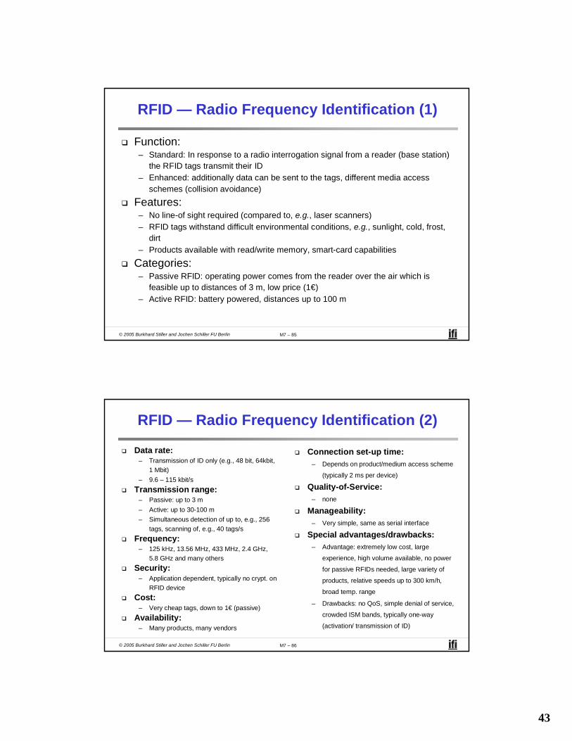
RFID — Radio Frequency Identification (1)
Function:– Standard: In response to a radio interrogation signal from a reader (base station)
the RFID tags transmit their ID– Enhanced: additionally data can be sent to the tags, different media access
schemes (collision avoidance)
Features:– No line-of sight required (compared to, e.g., laser scanners)– RFID tags withstand difficult environmental conditions, e.g., sunlight, cold, frost,
dirt– Products available with read/write memory, smart-card capabilities
Categories:– Passive RFID: operating power comes from the reader over the air which is
feasible up to distances of 3 m, low price (1€)– Active RFID: battery powered, distances up to 100 m
© 2005 Burkhard Stiller and Jochen Schiller FU Berlin M7 – 86
RFID — Radio Frequency Identification (2)
Data rate:– Transmission of ID only (e.g., 48 bit, 64kbit,
1 Mbit)– 9.6 – 115 kbit/s
Transmission range:– Passive: up to 3 m– Active: up to 30-100 m– Simultaneous detection of up to, e.g., 256
tags, scanning of, e.g., 40 tags/sFrequency:
– 125 kHz, 13.56 MHz, 433 MHz, 2.4 GHz, 5.8 GHz and many others
Security:– Application dependent, typically no crypt. on
RFID deviceCost:
– Very cheap tags, down to 1€ (passive)Availability:
– Many products, many vendors
Connection set-up time:– Depends on product/medium access scheme
(typically 2 ms per device)
Quality-of-Service:– none
Manageability:– Very simple, same as serial interface
Special advantages/drawbacks:– Advantage: extremely low cost, large
experience, high volume available, no power
for passive RFIDs needed, large variety of
products, relative speeds up to 300 km/h,
broad temp. range
– Drawbacks: no QoS, simple denial of service,
crowded ISM bands, typically one-way
(activation/ transmission of ID)

44
© 2005 Burkhard Stiller and Jochen Schiller FU Berlin M7 – 87
RFID – Radio Frequency Identification (3)
Applications:– Total asset visibility: tracking of goods during manufacturing, localization of
pallets, goods etc.– Loyalty cards: customers use RFID tags for payment at, e.g., gas stations,
collection of buying patterns– Automated toll collection: RFIDs mounted in windshields allow commuters to drive
through toll plazas without stopping– Others: access control, animal identification, tracking of hazardous material,
inventory control, warehouse management, ...
Local Positioning Systems:– GPS useless indoors or underground, problematic in cities with high buildings– RFID tags transmit signals, receivers estimate the tag location by measuring the
signal‘s time of flight
© 2005 Burkhard Stiller and Jochen Schiller FU Berlin M7 – 88
RFID – Radio Frequency Identification (4)
Security:– Denial-of-Service attacks are always possible
• Interference of the wireless transmission, shielding of transceivers – IDs via manufacturing or one time programming– Key exchange via, e.g., RSA possible, encryption via, e.g., AES
Future Trends:– RTLS: Real-Time Locating System – big efforts to make total asset visibility come
true– Integration of RFID technology into the manufacturing, distribution and logistics
chain– Creation of „electronic manifests“ at item or package level (embedded
inexpensive passive RFID tags)– 3D tracking of children, patients

45
© 2005 Burkhard Stiller and Jochen Schiller FU Berlin M7 – 89
RFID – Radio Frequency Identification (5)
Devices and Companies:– AXCESS Inc., www.axcessinc.com– Checkpoint Systems Group, www.checkpointsystems.com– GEMPLUS, www.gemplus.com/app/smart_tracking– Intermec/Intellitag, www.intermec.com– I-Ray Technologies, www.i-ray.com– RF Code, www.rfcode.com– Texas Instruments, www.ti-rfid.com/id– WhereNet, www.wherenet.com– Wireless Mountain, www.wirelessmountain.com– XCI, www.xci-inc.com
Only a very small selection …
© 2005 Burkhard Stiller and Jochen Schiller FU Berlin M7 – 90
RFID – Radio Frequency Identification (6)
Example Product: Intermec RFID UHF OEM Reader– Read range up to 7m– Anti-collision algorithm allows for scanning of 40 tags per second regardless of
the number of tags within the reading zone– US: unlicensed 915 MHz, Frequency Hopping– Read: 8 byte < 32 ms– Write: 1 byte < 100ms
Example Product: Wireless Mountain Spider– Proprietary sparse code anti-collision algorithm– Detection range 15 m indoor, 100 m line-of-sight– > 1 billion distinct codes– Read rate > 75 tags/s– Operates at 308 MHz

46
© 2005 Burkhard Stiller and Jochen Schiller FU Berlin M7 – 91
RFID – Radio Frequency Identification (7)
Relevant Standards– American National Standards Institute
• ANSI, www.ansi.org, www.aimglobal.org/standards/rfidstds/ANSIT6.html– Automatic Identification and Data Capture Techniques
• JTC 1/SC 31, www.uc-council.com/sc31/home.htm, www.aimglobal.org/standards/rfidstds/sc31.htm
– European Radio Communications Office• ERO, www.ero.dk, www.aimglobal.org/standards/rfidstds/ERO.htm
– European Telecommunications Standards Institute• ETSI, www.etsi.org, www.aimglobal.org/standards/rfidstds/ETSI.htm
– Identification Cards and related devices• JTC 1/SC 17, www.sc17.com, www.aimglobal.org/standards/rfidstds/sc17.htm,
– Identification and communication• ISO TC 104 / SC 4, www.autoid.org/tc104_sc4_wg2.htm,
www.aimglobal.org/standards/rfidstds/TC104.htm – Road Transport and Traffic Telematics
• CEN TC 278, www.nni.nl, www.aimglobal.org/standards/rfidstds/CENTC278.htm– Transport Information and Control Systems
• ISO/TC204, www.sae.org/technicalcommittees/gits.htm, www.aimglobal.org/standards/rfidstds/ISOTC204.htm
© 2005 Burkhard Stiller and Jochen Schiller FU Berlin M7 – 92
RFID – Radio Frequency Identification (8)
ISO Standards– ISO 15418
• MH10.8.2 Data Identifiers• EAN.UCC Application Identifiers
– ISO 15434 - Syntax for High Capacity ADC Media– ISO 15962 - Transfer Syntax– ISO 18000
• Part 2, 125-135 kHz• Part 3, 13.56 MHz• Part 4, 2.45 GHz• Part 5, 5.8 GHz• Part 6, UHF (860-930 MHz, 433 MHz)
– ISO 18047 - RFID Device Conformance Test Methods– ISO 18046 - RF Tag and Interrogator Performance Test Methods

47
© 2005 Burkhard Stiller and Jochen Schiller FU Berlin M7 – 93
Bluetooth may act like a rogue member of the 802.11 network:– Does not know anything about gaps, inter frame spacing
IEEE 802.15-2 discusses these problems:– Proposal: Adaptive Frequency Hopping
• A non-collaborative Coexistence MechanismReal effects?– Many different opinions, publications, tests, formulae:– Results from complete breakdown to almost no effect– Bluetooth (FHSS) seems more robust than 802.11b (DSSS)
802.11 versus 802.15/Bluetooth
t
f [MHz]
2402
2480 802.11b 3 channels(separated by installation)
AC
K
DIF
S
DIF
S
SIF
S
1000 byte SIF
S
DIF
S
500 byte AC
K
DIF
S
500 byte
SIF
SA
CK
DIF
S
500 byte
DIF
S 100byte S
IFS
AC
K
DIF
S 100byte S
IFS
AC
K
DIF
S 100byte S
IFS
AC
K
DIF
S 100byte S
IFS
AC
K
DIF
S 100byte S
IFS
AC
K
802.15.1 79 channels(separated by hopping pattern)