Embed Size (px)
Citation preview
Technical Report
Background of SIFs and Stress Indicesfor Moment Loadings of PipingComponents
This report describes research sponsored by EPRI and the U.S. Department of Energy (Award No. DE-FC02-00NE22796).

EPRI Project Manager R. Carter
Electric Power Research Institute • 3420 Hillview Avenue, Palo Alto, California 94304 • PO Box 10412, Palo Alto, California 94303 • USA 800.313.3774 • 650.855.2121 • [email protected] • www.epri.com
Background of SIFs and Stress Indices for Moment Loadings of Piping Components
1012078
Final Report, June 2005
Cosponsor U.S. Department of Energy 1000 Independence Avenue Washington, DC
DISCLAIMER OF WARRANTIES AND LIMITATION OF LIABILITIES
THIS DOCUMENT WAS PREPARED BY THE ORGANIZATION(S) NAMED BELOW AS AN ACCOUNT OF WORK SPONSORED OR COSPONSORED BY THE ELECTRIC POWER RESEARCH INSTITUTE, INC. (EPRI). NEITHER EPRI, ANY MEMBER OF EPRI, ANY COSPONSOR, THE ORGANIZATION(S) BELOW, NOR ANY PERSON ACTING ON BEHALF OF ANY OF THEM:
(A) MAKES ANY WARRANTY OR REPRESENTATION WHATSOEVER, EXPRESS OR IMPLIED, (I) WITH RESPECT TO THE USE OF ANY INFORMATION, APPARATUS, METHOD, PROCESS, OR SIMILAR ITEM DISCLOSED IN THIS DOCUMENT, INCLUDING MERCHANTABILITY AND FITNESS FOR A PARTICULAR PURPOSE, OR (II) THAT SUCH USE DOES NOT INFRINGE ON OR INTERFERE WITH PRIVATELY OWNED RIGHTS, INCLUDING ANY PARTY'S INTELLECTUAL PROPERTY, OR (III) THAT THIS DOCUMENT IS SUITABLE TO ANY PARTICULAR USER'S CIRCUMSTANCE; OR
(B) ASSUMES RESPONSIBILITY FOR ANY DAMAGES OR OTHER LIABILITY WHATSOEVER (INCLUDING ANY CONSEQUENTIAL DAMAGES, EVEN IF EPRI OR ANY EPRI REPRESENTATIVE HAS BEEN ADVISED OF THE POSSIBILITY OF SUCH DAMAGES) RESULTING FROM YOUR SELECTION OR USE OF THIS DOCUMENT OR ANY INFORMATION, APPARATUS, METHOD, PROCESS, OR SIMILAR ITEM DISCLOSED IN THIS DOCUMENT.
ORGANIZATION(S) THAT PREPARED THIS DOCUMENT
Wais and Associates, Inc.
ORDERING INFORMATION
Requests for copies of this report should be directed to EPRI Orders and Conferences, 1355 Willow Way, Suite 278, Concord, CA 94520, (800) 313-3774, press 2 or internally x5379, (925) 609-9169, (925) 609-1310 (fax).
Electric Power Research Institute and EPRI are registered service marks of the Electric Power Research Institute, Inc.
Copyright © 2005 Electric Power Research Institute, Inc. All rights reserved.
iii
CITATIONS
This report was prepared by
Wais and Associates, Inc. 2475 Spalding Drive Atlanta, Georgia 30350 [email protected]
Principal Investigators E. A. Wais E. C. Rodabaugh
This report describes research sponsored by the Electric Power Research Institute (EPRI) and the U.S. Department of Energy (DE-FC02-00NE22796. Task 01-3-24.5).
The report is a corporate document that should be cited in the literature in the following manner:
Background of SIFs and Stress Indices for Moment Loadings of Piping Components. EPRI, Palo Alto, CA, and U.S. Department of Energy, Washington, D.C.: 2005. 1012078.

v
REPORT SUMMARY
Design and engineering for fatigue are major concerns in piping systems. Stress indices and stress intensification factors (SIFs) are used in the design of piping systems that must meet the requirements of American Society of Mechanical Engineers (ASME) Section III Code. The majority of SIFs and indices were developed years ago when only relatively unsophisticated analysis methods were available. Many of these parameters are very conservative and result in expensive inspections, design modifications, and even replacements. This report reviews the background and references of stress indices and stress intensification factors for moment loadings for various piping components.
Background SIFs are often confused with stress concentration factors, stress indices, stress coefficients, factors used for evaluating crack propagation, and other multipliers that are used in various aspects of piping design and analysis. SIFs are actually fatigue correlation factors that compare the fatigue life of piping components (for example, tees and branch connections) to that of girth butt welds in straight pipe subjected to bending moments.
ASME Section III Code uses factors such as C2 and K2 indices to account for fatigue effects produced by reversing loads. For piping systems designed to Class 1 requirements of ASME Section III, stress indices are used to evaluate specific stress limits. Stress indices also are used when analysis is performed to determine fatigue usage factor.
Objectives To provide historical information, source references, and equations to enable analysts to understand the background or basis of the various SIFs and stress indices for moment loading of piping components and to understand the degree of conservatism of these parameters.
Approach A review of the present approach for evaluating SIFs and stress indices according to ASME and American National Standards Institute (ANSI) codes for piping design provided an understanding of the current methodology. The project team collected and reviewed available data on studies, experiments, and testing.
Results This report provides background information, references, and equations for twenty-four piping components (thirteen component SIFs and eleven component stress indices) that justify the values or expressions for the SIFs and indices.
vi
EPRI Perspective Design for fatigue is a significant concern for any power or process facility. Accurate methods of engineering for fatigue are important for cost-effective design, root cause failures, and evaluation of remaining fatigue life of plant designs. This work continues to establish the technical justification that allows for reductions in current ASME Code stress indices. These and associated reductions in design stresses can provide a basis to reduce the scope of ongoing pressure boundary component testing and inspection programs for operating nuclear power plants. Examples include reductions in both the inspection scope of postulated high- and moderate-energy line break locations and snubber testing.
Keywords ASME code Fatigue Piping design and analysis Stress intensification factors Stress indices
ABSTRACT
Stress indices and stress intensification factors are used in the design of piping systems that must satisfy the requirements of ASME Section III for Class 1 and Class 2 systems. Section III is continuingly reviewing and modifying the indices and stress intensification factors. For some components, these parameters have remained fairly constant. For others, there have been many changes. This report reviews the background and references of the stress indices and stress intensification factors for moment loadings for the various piping components. The purpose of this effort is to provide the analyst with more understanding of the basis of the analysis methodology of these components.
vii

CONTENTS
1 INTRODUCTION ....................................................................................................................1-1 1.1 Background .....................................................................................................................1-1 1.2 Nomenclature..................................................................................................................1-1 1.3 Background of Stress Intensification Factors ..................................................................1-2
1.3.1 Failure Mechanisms ................................................................................................1-3 1.3.2 Basis of the B31 Approach ......................................................................................1-3 1.3.3 Girth Butt Welds as Base Line.................................................................................1-4 1.3.4 Background of Stress Intensification Factors ..........................................................1-5
1.4 Background of ASME Section III Stress Indices .............................................................1-6 1.4.1 Primary Stress Indices.............................................................................................1-6 1.4.2 Primary Plus Secondary Stress Indices ..................................................................1-6 1.4.3 Peak Stress Indices.................................................................................................1-6
1.5 Application of Indices and SIFs.......................................................................................1-7
2 STRESS INTENSIFICATION FACTORS ...............................................................................2-1 2.1 Objective .........................................................................................................................2-1 2.2 Welding Elbow or Pipe Bend...........................................................................................2-1 2.3 Miter Bend.......................................................................................................................2-1 2.4 Welding Tee per ANSI B16.9 ..........................................................................................2-2 2.5 Reinforced Fabricated Tee..............................................................................................2-2 2.6 Branch Connection or Unreinforced Fabricated Tee.......................................................2-3 2.7 Fillet Welded and Partial Penetration Welded Branch Connections ...............................2-3 2.8 Girth Butt Weld................................................................................................................2-4 2.9 Circumferential Fillet Welded or Socket Welded Joints...................................................2-4 2.10 Brazed Joint ..................................................................................................................2-4 2.11 30 Degree Tapered Transition (ANSI B16.25) ..............................................................2-5 2.12 Concentric and Eccentric Reducers (ANSI B16.9)........................................................2-5 2.13 Threaded Pipe Joint or Threaded Flange......................................................................2-5 2.14 Corrugated Straight Pipe or Corrugated or Creased Bend ...........................................2-6
ix
3 STRESS INDICES ..................................................................................................................3-1 3.1 Introduction .....................................................................................................................3-1 3.2 Straight Pipe, Remote from Welds or Other Discontinuites ............................................3-1 3.3 Longitudinal Butt Welds In Straight Pipe .........................................................................3-1 3.4 Girth Butt Welds Between Components of Nominally Identical Wall Thickness Items .....................................................................................................................................3-2 3.5 Girth Fillet Weld to Socket Weld Fittings, Socket Weld Valves, Slip-on or Socket Welding Flanges ...................................................................................................................3-2 3.6 NB-4250 Transitions........................................................................................................3-3 3.7 Transitions Within a 1:3 Slope.........................................................................................3-3 3.8 Butt Welded Reducers per ANSI B16.9 or MSS SP-87 ..................................................3-3 3.9 Curved Pipe or Butt Welded Elbows ...............................................................................3-4 3.10 Branch Connections per NB-3643.................................................................................3-4 3.11 Butt Welding Tees.........................................................................................................3-4
4 REFERENCES .......................................................................................................................4-1
x
1-1
1 INTRODUCTION
1.1 Background
For piping systems designed to the Class 2 or 3 requirements of the ASME Code, Section III [1], stress intensification factors (SIFs) are used to evaluate moment loading. The SIFs actually are “fatigue correlation factors” that compare the fatigue life of piping components (tees, branch connections, etc.) to that of girth butt welds in straight pipe subjected to bending moments.
For piping systems designed to the Class 1 requirements of ASME Code Section III, stress indices are used in evaluating specific stress limits. In addition, these indices are used when analysis is performed to determine the fatigue usage factor. The Code provides indices applicable to moment loading, internal pressure loading and thermal transient loading (e.g. thermal shock). This study focuses on the indices associated with moment loading, i.e. B2, C2 and K2.
This report provides the historical background and basis of the SIFs and stress indices. References are identified which provide the justification of the values or expressions for the SIFs and indices. This information will provide the analyst with insight to the degree of conservatism in the SIFs and indices.
1.2 Nomenclature
The basic nomenclature is in accordance with NB-3683.1 and NC-3673.2 of the ASME Boiler and Pressure Code, Section III, [1]. Figure NC-3673.2(b)-1 provides details regarding the nomenclature. The following is a listing of nomenclature referenced in this report. For nomenclature not included herein, Reference 1 should be utilized.
α = cone angle in degrees D1 = outside diameter at large end of reducer, inches D2 = outside diameter at small end of reducer, inches Dn/tn = the larger of D1/t1 and D2/t2 L1 = distance between weld location and the end of the transition radius at the large end of reducer, inches L2 = distance between weld location and the end of the transition radius at the small end of the reducer, inches r1 = transition radius at large end of reducer, inches r2 = transition radius at small end of reducer, inches
Introduction
1-2
t1 = wall thickness at large end of reducer, inches t2 = wall thickness at small end of reducer, inches B2 = stress index related to primary stress intensity C2 = stress index related to secondary stress intensity Cx = dimension associated with socket welds Do = outside diameter of the pipe, inches. i = stress intensification factor K2 = stress index related to peak stress intensity M = bending moment, in-lb. N = number of cycles to failure tn = nominal thickness of the pipe Z = section modulus of the pipe or component as specified in [1], in3
1.3 Background of Stress Intensification Factors
In order to understand the background of SIFs it is necessary to review the history of the piping codes and the methodologies that were available for design engineers at various times. The theoretical basis for the code equations and the various failure mechanisms they address must also be understood. SIFs are often confused with stress concentration factors, stress indices, stress coefficients, factors used for evaluating crack propagation, and other multipliers that are use in various aspects of piping design and analysis.
As will be discussed later in this report, the early ASME Section III, “Rules for Construction of Nuclear Power Plant Components”, criteria for Class 1 piping was based on B31.7, “Nuclear Piping” [2].
For Class 2 piping, the criteria was based on B31.1, “Power Piping” [3]. The equations, SIFs, etc. were based on B31.1. Hence to understand the basis for the Section III indices, the background of B31.1 must also be understood. In some cases there were additional requirements imposed on the SIFs and overall requirements.
In 1935 the first version of B31.1 was introduced. However, it was not until the 1950s that fatigue was specifically addressed. In 1951 a task force was established with the purpose of studying the existing current rules which addressed stresses and other items. The results of this task force would prove to be very significant, in that they addressed fatigue directly and focused on the concept of “stress range”.
A draft of the rules was published in 1953 and a summary of the results was presented at the Annual Meeting of the ASME in 1953. This summary was published in the ASME transactions in 1955. Markl [4] provides an excellent summary of the background and the proposed rules. The rules were initially incorporated in the Code in 1955. Since that time, they were modified as more information and analysis methods became more advanced.
Introduction
It is important to recognize the time frame in which these rules were first integrated in to the Code. Analysis methodologies, by necessity, were simple. Computers were not available for what we now accept as standard practice for computer analysis of piping systems. By necessity, hand calculations, or methods using charts or graphs were used.
1.3.1 Failure Mechanisms
There are several mechanisms of failure that must be considered in the design of piping systems. These include, but are not limited to:
• Bursting due to pressure
• Collapse due to dead weight loads
• Fatigue due to thermal cycling
• Corrosion
Bursting due to pressure is addressed by specifying a minimum wall thickness for the pipe and the various components. Collapse, due to dead weight or seismic loads, is covered by ensuring that there are enough pipe supports so that collapse will not occur. This can be accomplished by either specifying a minimum number of supports (e.g. per a specified length of pipe between supports) or a stress criterion. Fatigue due to thermal expansion cycling was a major concern and is directly related to SIFs. The thermal cycling typically was due to start up and shut down of a plant on daily basis. As considered by B31, the typical plant life was 20 years; hence the plant was designed for approximately 7000 cycles (20 years x 365 days/year = 7300 cycles). Corrosion was covered by the specification of minimum wall thickness.
1.3.2 Basis of the B31 Approach
As discussed earlier, the analysis methodology was simplified. The approach was based on moment induced stresses. The effects of axial forces (and other forces) were only implicitly addressed. Because of the need for simplicity in the analysis methodology, the limits (or allowables) needed to be conservative. The approach was based on moment induced stresses. The effects of axial forces (and other forces) were only implicitly addressed.
The concept of “stress range” was introduced in 1953. The Code is based on a material’s allowable stress at temperature, Sh, which is taken as the lesser of 1/4 minimum tensile strength or 5/8 minimum yield strength at a specific temperature. Consider a piping system that cycles from a cold condition at a temperature, Tc, to the hot condition at Th. If the stresses induced by thermal expansion at Th are greater than 1.6 Sh then there will be plastic deformation since 1.6Sh = Sy. Similarly at Tc, if the stresses are over 1.6 Sc there will also be plastic deformation. In other words, at either end of the operating cycle from cold to hot condition, if the stresses exceed Sy there will be plastic “flow”. The maximum stress “range” where there would be no “flow” (assuming no creep behavior) at either end of the cycle would be:
1-3
Introduction
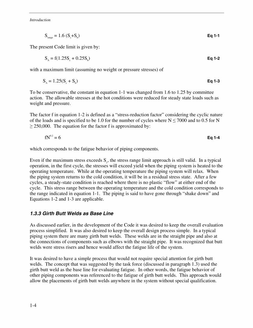
Srange = 1.6 (Sc+Sh) Eq 1-1
The present Code limit is given by:
SA = f(1.25Sc + 0.25Sh) Eq 1-2
with a maximum limit (assuming no weight or pressure stresses) of
SA = 1.25(Sc + Sh) Eq 1-3
To be conservative, the constant in equation 1-1 was changed from 1.6 to 1.25 by committee action. The allowable stresses at the hot conditions were reduced for steady state loads such as weight and pressure.
The factor f in equation 1-2 is defined as a “stress-reduction factor” considering the cyclic nature of the loads and is specified to be 1.0 for the number of cycles where N ≤ 7000 and to 0.5 for N ≥ 250,000. The equation for the factor f is approximated by:
fN0.2 = 6 Eq 1-4
which corresponds to the fatigue behavior of piping components.
Even if the maximum stress exceeds Sy, the stress range limit approach is still valid. In a typical operation, in the first cycle, the stresses will exceed yield when the piping system is heated to the operating temperature. While at the operating temperature the piping system will relax. When the piping system returns to the cold condition, it will be in a residual stress state. After a few cycles, a steady-state condition is reached where there is no plastic “flow” at either end of the cycle. This stress range between the operating temperature and the cold condition corresponds to the range indicated in equation 1-1. The piping is said to have gone through “shake down” and Equations 1-2 and 1-3 are applicable.
1.3.3 Girth Butt Welds as Base Line
As discussed earlier, in the development of the Code it was desired to keep the overall evaluation process simplified. It was also desired to keep the overall design process simple. In a typical piping system there are many girth butt welds. These welds are in the straight pipe and also at the connections of components such as elbows with the straight pipe. It was recognized that butt welds were stress risers and hence would affect the fatigue life of the system.
It was desired to have a simple process that would not require special attention for girth butt welds. The concept that was suggested by the task force (discussed in paragraph 1.3) used the girth butt weld as the base line for evaluating fatigue. In other words, the fatigue behavior of other piping components was referenced to the fatigue of girth butt welds. This approach would allow the placements of girth butt welds anywhere in the system without special qualification.
1-4
Introduction
1-5
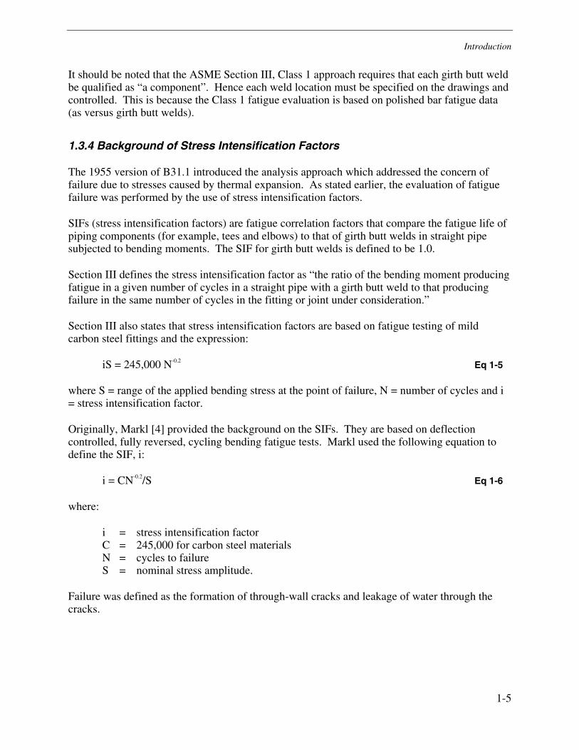
It should be noted that the ASME Section III, Class 1 approach requires that each girth butt weld be qualified as “a component”. Hence each weld location must be specified on the drawings and controlled. This is because the Class 1 fatigue evaluation is based on polished bar fatigue data (as versus girth butt welds).
1.3.4 Background of Stress Intensification Factors
The 1955 version of B31.1 introduced the analysis approach which addressed the concern of failure due to stresses caused by thermal expansion. As stated earlier, the evaluation of fatigue failure was performed by the use of stress intensification factors.
SIFs (stress intensification factors) are fatigue correlation factors that compare the fatigue life of piping components (for example, tees and elbows) to that of girth butt welds in straight pipe subjected to bending moments. The SIF for girth butt welds is defined to be 1.0.
Section III defines the stress intensification factor as “the ratio of the bending moment producing fatigue in a given number of cycles in a straight pipe with a girth butt weld to that producing failure in the same number of cycles in the fitting or joint under consideration.”
Section III also states that stress intensification factors are based on fatigue testing of mild carbon steel fittings and the expression:
iS = 245,000 N-0.2 Eq 1-5
where S = range of the applied bending stress at the point of failure, N = number of cycles and i = stress intensification factor.
Originally, Markl [4] provided the background on the SIFs. They are based on deflection controlled, fully reversed, cycling bending fatigue tests. Markl used the following equation to define the SIF, i:
i = CN-0.2/S Eq 1-6
where:
i = stress intensification factor C = 245,000 for carbon steel materials N = cycles to failure S = nominal stress amplitude.
Failure was defined as the formation of through-wall cracks and leakage of water through the cracks.

Introduction
1.4 Background of ASME Section III Stress Indices
Stress indices were first used in USAS B31.7 in 1969 [2]. B31.7 was used for evaluation of Class 1 piping and referenced B31.1 for Class 2 piping for nuclear power plants. Later, B31.7 was incorporated into ASME Section III of the ASME Boiler & Pressure Vessel Code [1]. Presently paragraph NB-3682 of Section III states:
“The general definition of a stress index for mechanical loads is: B, C, K or i = σ/S
where
S = nominal stress, psi (kPa), due to load L σ = elastic stress, psi (kPa), due to load L
For B indices, σ represents the stress magnitude corresponding to a limit load. For C or K indices, σ represents the maximum stress intensity due to load L. For i factors, σ represents the principal stress at a particular point, surface, and direction due to load L……”
It should be noted that the statement that “i = σ/S” is incorrect and should be deleted.
As discussed in B31.7, the B2 indices “are based on a limit load type of analysis”, C indices “represent the Primary-plus-Secondary stresses” and “the K-indices represent peak stresses”.
These indices are discussed in more detail in the following sections.
1.4.1 Primary Stress Indices
The B2 indices are used to evaluate the primary stress of the component due to moment loading from sources such as weight or seismic loads. As stated in B31.7 [2] “B-indices are based on a limit load type of analysis.”
1.4.2 Primary Plus Secondary Stress Indices
The C2 indices are used to determine the level of the primary plus secondary stress intensity level in the component being investigated. The loading conditions include thermal expansion, seismic loads, etc. As discussed in reference 2, “C-indices represent the Primary-plus-Secondary stresses.”
1.4.3 Peak Stress Indices
The K2 indices are used, with the C2 indices, to determine the peak stress intensity. The peak stress intensity is used for evaluating the fatigue life. The loading conditions of concern are the same as for the primary plus secondary stress indices. The peak stress is given by C2K2M/Z. As discussed in reference 2, the “K-indices represent peak stresses which are involved in a fatigue evaluation.”
1-6
Introduction
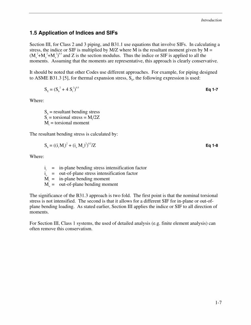
1.5 Application of Indices and SIFs
Section III, for Class 2 and 3 piping, and B31.1 use equations that involve SIFs. In calculating a stress, the indice or SIF is multiplied by M/Z where M is the resultant moment given by M = (Mx
2+My
2+Mz
2)0.5 and Z is the section modulus. Thus the indice or SIF is applied to all the moments. Assuming that the moments are representative, this approach is clearly conservative.
It should be noted that other Codes use different approaches. For example, for piping designed to ASME B31.3 [5], for thermal expansion stress, SE, the following expression is used:
SE = (Sb
2 + 4 St
2)0.5 Eq 1-7
Where:
Sb = resultant bending stress St = torsional stress = Mt/2Z Mt = torsional moment
The resultant bending stress is calculated by:
Sb = ((ii Mi)2 + (io Mo)
2)0.5/Z Eq 1-8
Where:
ii = in-plane bending stress intensification factor io = out-of-plane stress intensification factor Mi = in-plane bending moment Mo = out-of-plane bending moment
The significance of the B31.3 approach is two fold. The first point is that the nominal torsional stress is not intensified. The second is that it allows for a different SIF for in-plane or out-of-plane bending loading. As stated earlier, Section III applies the indice or SIF to all direction of moments.
For Section III, Class 1 systems, the used of detailed analysis (e.g. finite element analysis) can often remove this conservatism.
1-7

2-1
2 STRESS INTENSIFICATION FACTORS
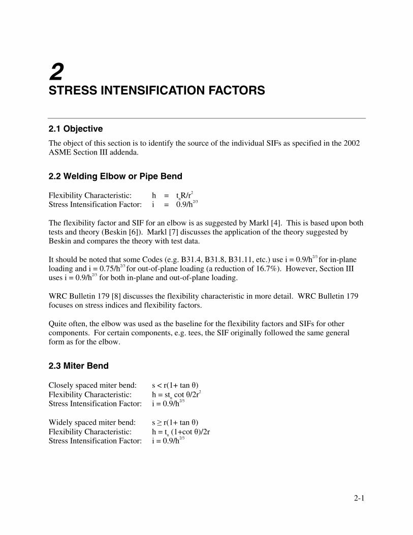
2.1 Objective
The object of this section is to identify the source of the individual SIFs as specified in the 2002 ASME Section III addenda.
2.2 Welding Elbow or Pipe Bend
Flexibility Characteristic: h = tnR/r2 Stress Intensification Factor: i = 0.9/h2/3
The flexibility factor and SIF for an elbow is as suggested by Markl [4]. This is based upon both tests and theory (Beskin [6]). Markl [7] discusses the application of the theory suggested by Beskin and compares the theory with test data.
It should be noted that some Codes (e.g. B31.4, B31.8, B31.11, etc.) use i = 0.9/h2/3 for in-plane loading and i = 0.75/h2/3 for out-of-plane loading (a reduction of 16.7%). However, Section III uses i = 0.9/h2/3 for both in-plane and out-of-plane loading.
WRC Bulletin 179 [8] discusses the flexibility characteristic in more detail. WRC Bulletin 179 focuses on stress indices and flexibility factors.
Quite often, the elbow was used as the baseline for the flexibility factors and SIFs for other components. For certain components, e.g. tees, the SIF originally followed the same general form as for the elbow.
2.3 Miter Bend
Closely spaced miter bend: s < r(1+ tan θ) Flexibility Characteristic: h = stn cot θ/2r2 Stress Intensification Factor: i = 0.9/h2/3
Widely spaced miter bend: s ≥ r(1+ tan θ) Flexibility Characteristic: h = tn (1+cot θ)/2r Stress Intensification Factor: i = 0.9/h2/3
Stress Intensification Factors
2-2
The flexibility factor and SIF are also based upon Markl [7]. Both closely spaced and widely spaced miter bends are discussed. The parameter, s, is the crotch spacing between miters.
The overall approach used was to develop an “effective bend radius” and use the general approach suggested for elbows.
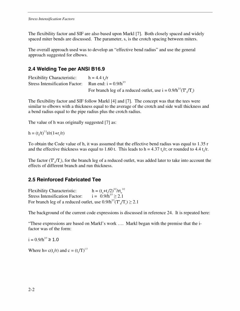
2.4 Welding Tee per ANSI B16.9
Flexibility Characteristic: h = 4.4 tn/r Stress Intensification Factor: Run end: i = 0.9/h2/3 For branch leg of a reduced outlet, use i = 0.9/h2/3(T′b/Tr)
The flexibility factor and SIF follow Markl [4] and [7]. The concept was that the tees were similar to elbows with a thickness equal to the average of the crotch and side wall thickness and a bend radius equal to the pipe radius plus the crotch radius.
The value of h was originally suggested [7] as:
h = (te/t)2.5t/r(1+rc/r)
To obtain the Code value of h, it was assumed that the effective bend radius was equal to 1.35 r and the effective thickness was equal to 1.60 t. This leads to h = 4.37 tn/r; or rounded to 4.4 tn/r.
The factor (T′b/Tr), for the branch leg of a reduced outlet, was added later to take into account the effects of different branch and run thickness.
2.5 Reinforced Fabricated Tee
Flexibility Characteristic: h = (tn+te/2)5/2/rtn
3/2 Stress Intensification Factor: i = 0.9/h2/3 ≥ 2.1 For branch leg of a reduced outlet, use 0.9/h2/3(T′b/Tr) ≥ 2.1
The background of the current code expressions is discussed in reference 24. It is repeated here:
“These expressions are based on Markl’s work …. Markl began with the premise that the i-factor was of the form:
i = 0.9/h2/3 ≥ 1.0
Where h= c(te/r) and c = (te/T)1.5
Stress Intensification Factors
Markl called h, the effective flexibility factor, and said that c takes account of the increased section modulus. Both of these factors are a function of the effective fitting thickness at the juncture, te, which Markl saw to be the average of the thickness of the run pipe and the thickness of the branch pipe (te =(T+t)/2. For a pad thickness, tr, and for a connection with t = T, then te = (T+tr+T)/2 = T+tr/2. Thus, Markl determined te to be the pipe wall thickness increased by one half the excess thickness, tr, provided in either the run or branch by use of thicker piping, or pad, or saddle. Note that Markl’s statement is for t = T.”
Note also that as for the Welding Tee, the general expression for the SIF is of the same form as for an elbow.
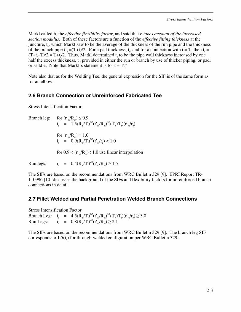
2.6 Branch Connection or Unreinforced Fabricated Tee
Stress Intensification Factor:
Branch leg: for (r′m/Rm) ≤ 0.9 ib = 1.5(Rm/Tr)
2/3(r′m/Rm)1/2(Tb′/Tr)(r′m/rp)
for (r′m/Rm) = 1.0 ib = 0.9(Rm/Tr)
2/3(r′m/rp) < 1.0
for 0.9 < (r′m/Rm)< 1.0 use linear interpolation
Run legs: ir = 0.4(Rm/Tr)2/3(r′m/Rm) ≥ 1.5
The SIFs are based on the recommendations from WRC Bulletin 329 [9]. EPRI Report TR-110996 [10] discusses the background of the SIFs and flexibility factors for unreinforced branch connections in detail.
2.7 Fillet Welded and Partial Penetration Welded Branch Connections
Stress Intensification Factor Branch Leg: ib = 4.5(Rm/Tr)
2/3(r′m/Rm)1/2(Tb′/Tr)(r′m/rp) ≥ 3.0 Run Legs: ir = 0.8(Rm/Tr)
2/3(r′m/Rm) ≥ 2.1
The SIFs are based on the recommendations from WRC Bulletin 329 [9]. The branch leg SIF corresponds to 1.5(ib) for through-welded configuration per WRC Bulletin 329.
2-3
Stress Intensification Factors
2-4
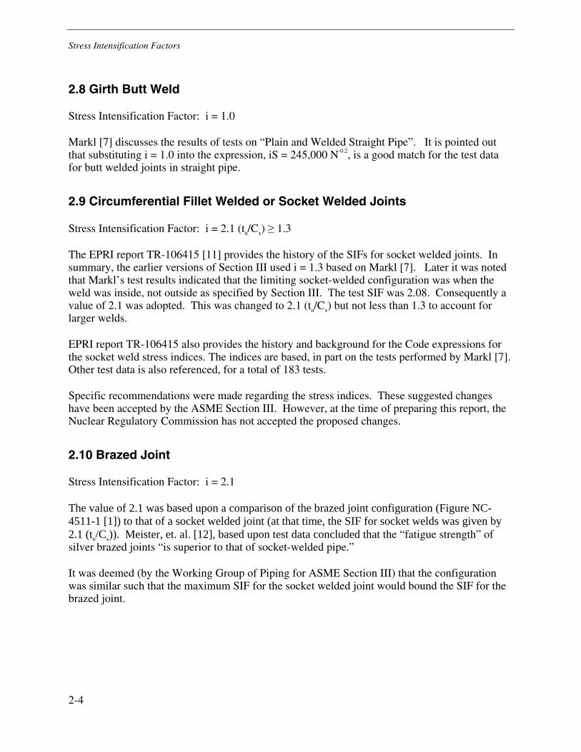
2.8 Girth Butt Weld
Stress Intensification Factor: i = 1.0
Markl [7] discusses the results of tests on “Plain and Welded Straight Pipe”. It is pointed out that substituting i = 1.0 into the expression, iS = 245,000 N-0.2, is a good match for the test data for butt welded joints in straight pipe.
2.9 Circumferential Fillet Welded or Socket Welded Joints
Stress Intensification Factor: i = 2.1 (tn/Cx) ≥ 1.3
The EPRI report TR-106415 [11] provides the history of the SIFs for socket welded joints. In summary, the earlier versions of Section III used i = 1.3 based on Markl [7]. Later it was noted that Markl’s test results indicated that the limiting socket-welded configuration was when the weld was inside, not outside as specified by Section III. The test SIF was 2.08. Consequently a value of 2.1 was adopted. This was changed to 2.1 (tn/Cx) but not less than 1.3 to account for larger welds.
EPRI report TR-106415 also provides the history and background for the Code expressions for the socket weld stress indices. The indices are based, in part on the tests performed by Markl [7]. Other test data is also referenced, for a total of 183 tests.
Specific recommendations were made regarding the stress indices. These suggested changes have been accepted by the ASME Section III. However, at the time of preparing this report, the Nuclear Regulatory Commission has not accepted the proposed changes.
2.10 Brazed Joint
Stress Intensification Factor: i = 2.1
The value of 2.1 was based upon a comparison of the brazed joint configuration (Figure NC-4511-1 [1]) to that of a socket welded joint (at that time, the SIF for socket welds was given by 2.1 (tn/Cx)). Meister, et. al. [12], based upon test data concluded that the “fatigue strength” of silver brazed joints “is superior to that of socket-welded pipe.”
It was deemed (by the Working Group of Piping for ASME Section III) that the configuration was similar such that the maximum SIF for the socket welded joint would bound the SIF for the brazed joint.
Stress Intensification Factors
2-5
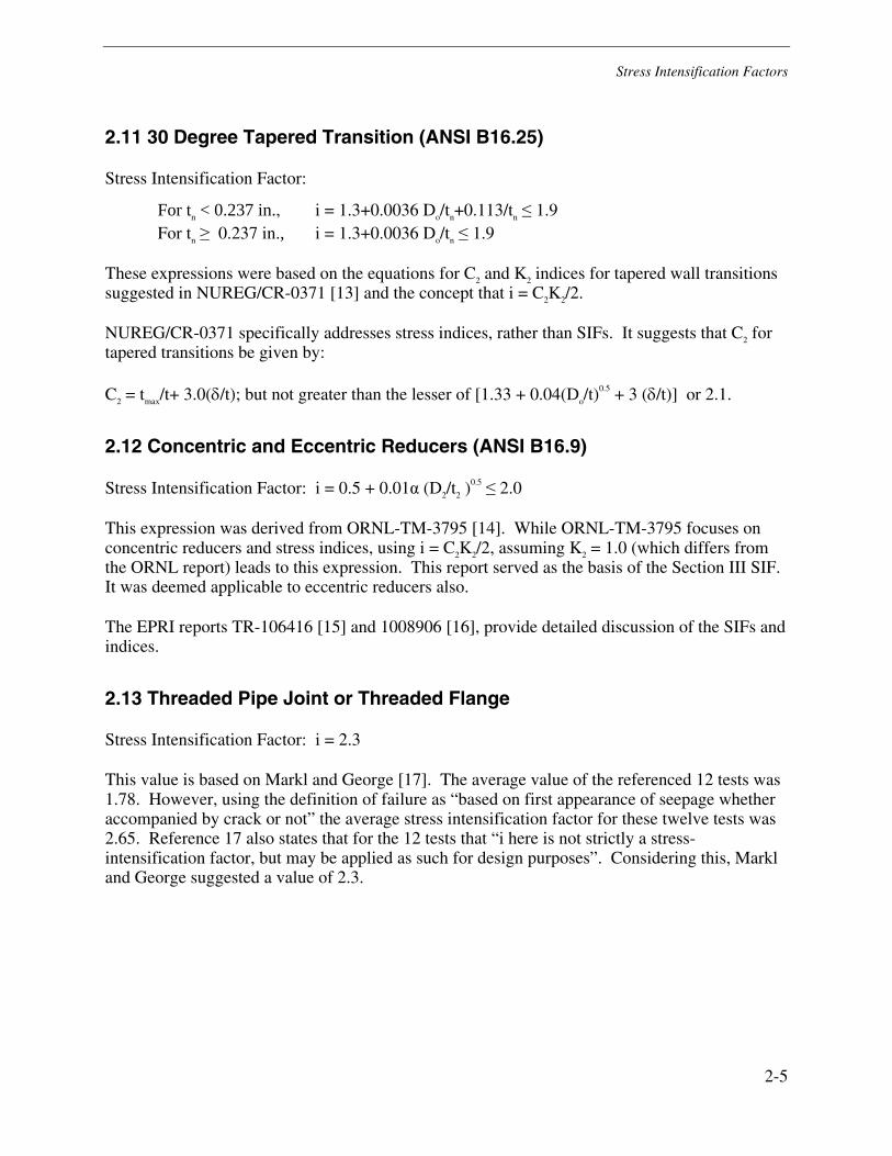
2.11 30 Degree Tapered Transition (ANSI B16.25)
Stress Intensification Factor:
For tn < 0.237 in., i = 1.3+0.0036 Do/tn+0.113/tn ≤ 1.9 For tn ≥ 0.237 in., i = 1.3+0.0036 Do/tn ≤ 1.9
These expressions were based on the equations for C2 and K2 indices for tapered wall transitions suggested in NUREG/CR-0371 [13] and the concept that i = C2K2/2.
NUREG/CR-0371 specifically addresses stress indices, rather than SIFs. It suggests that C2 for tapered transitions be given by:
C2 = tmax/t+ 3.0(δ/t); but not greater than the lesser of [1.33 + 0.04(Do/t)0.5 + 3 (δ/t)] or 2.1.
2.12 Concentric and Eccentric Reducers (ANSI B16.9)
Stress Intensification Factor: i = 0.5 + 0.01α (D2/t2 )0.5 ≤ 2.0
This expression was derived from ORNL-TM-3795 [14]. While ORNL-TM-3795 focuses on concentric reducers and stress indices, using i = C2K2/2, assuming K2 = 1.0 (which differs from the ORNL report) leads to this expression. This report served as the basis of the Section III SIF. It was deemed applicable to eccentric reducers also.
The EPRI reports TR-106416 [15] and 1008906 [16], provide detailed discussion of the SIFs and indices.
2.13 Threaded Pipe Joint or Threaded Flange
Stress Intensification Factor: i = 2.3
This value is based on Markl and George [17]. The average value of the referenced 12 tests was 1.78. However, using the definition of failure as “based on first appearance of seepage whether accompanied by crack or not” the average stress intensification factor for these twelve tests was 2.65. Reference 17 also states that for the 12 tests that “i here is not strictly a stress-intensification factor, but may be applied as such for design purposes”. Considering this, Markl and George suggested a value of 2.3.
Stress Intensification Factors
2.14 Corrugated Straight Pipe or Corrugated or Creased Bend
Stress Intensification Factor: i = 2.5
The value of 2.5 is based on Rossheim and Markl [18] which “substantially follows the recommendation given by Rossheim and Markl …in a paper evaluating the information available up to the year 1939…..”
Markl further states that this value is a “gross oversimplification” and that “A more thorough theoretical and experimental exploration of this type of construction appears urgently needed, if it is to be used in severe services.” In Rossheim and Markl [15] the recommendation of i = 2.5 was for “noncyclic” stresses which was defined as 20,000 cycles. A value of 5.0 was suggested for “cyclic loading” which was suggested to correspond to “500,000 stress reversals.”
2-6
3 STRESS INDICES
3.1 Introduction
The following sections provide the background for the stress indices associated with bending moments for the various pipe components.
The foreword to the USA Standard, USAS B31.7, “Nuclear Power Piping” [2] discusses the use and the basis of the stress indices. As discussed earlier, B31.7 was incorporated into ASME Section III.
The use of the stress intensification factors (SIFs) is restricted to moment loadings. The stress indices have a wider scope. As discussed in B31.7, “B-indices are based on a limit load type of analysis. C-indices represent the Primary-plus-Secondary stresses and, thirdly, the K-indices represent peak stresses which are involved in the fatigue evaluation. All three types of indices are used for internal pressure loads, moment loads and thermal gradient loads.”
This section discusses the stress indices for piping components subjected to moment loads.
3.2 Straight Pipe, Remote from Welds or Other Discontinuites
B2 = 1.0, C2 = 1.0, K2 = 1.0
The introduction to B31.7 includes a discussion of the use of stress indices and the limits of the Code. Straight pipe is discussed in detail. As a baseline for B2, a comparison of the limit load to the theoretical allowable load is made for straight pipe subjected to internal pressure, bending, and torsion on the pipe. The allowable load is based on the methodology discussed in Stokey, W.F., et. al. [19]. B31.7 discusses the conservativeness of the indices.
3.3 Longitudinal Butt Welds In Straight Pipe
(a) flush
B2 = 1.0, C2 =1.0, K2 = 1.1
(b) as-welded
B2 = 1.0, C2 =1.2, K2 = 1.3
3-1
Stress Indices
3-2
The values of the indices for longitudinal butt welds in straight pipe were established in B31.7 [2]. The values selected were based upon engineering judgment.
3.4 Girth Butt Welds Between Components of Nominally Identical Wall Thickness Items
(a) flush
B2 = 1.0, C2 =1.0, K2 = 1.1
(b) as-welded t > 3/16 in.
B2 = 1.0, C2 =1.0, K2 = 1.8
The introduction to B31.7 [2] discusses the justification for K2 = 1.8:
“Perhaps one of the most important of the K-indices is that for the girth butt-weld. Markl’s data on girth butt-welds with cyclic moment loading has been roughly confirmed in subsequent tests....Under B31.1, the stress intensification factor for a typical butt-weld is 1; doubling it gives a stress index of 2. But, considering the fabrication requirements in B31.7, and some engineering judgment a stress index of K2 = 1.8 has been assigned to girth butt welds. The quality of welds required for Class I piping in B31.7 should be considerably superior to those Markl tested. The stress index of 1.8 is probably conservative.”
NUREG/CR-0371 [13] provides a review of the background and history of the stress indices for girth welded joints. In a review of the available data, the conclusion is that “The test data indicate that K2 = 1.8 is conservative for “as-welded” girth butt welds in carbon steel pipe. The test data suggest that K2 =1.1 is appropriate for “flush” girth butt welds in carbon steel pipe.” There was “no attempt to establish a K2 index for stainless steel welds that is different...”
3.5 Girth Fillet Weld to Socket Weld Fittings, Socket Weld Valves, Slip-on or Socket Welding Flanges
B2 = 1.5, C2 = 2.1, K2 = 2.0
EPRI Report TR-106415 [11] provides the history and background for the Code expressions for the stress indices. The indices are based, in part on the tests performed by Markl [7]. Other test data is also referenced, for a total of 183 tests.
In EPRI report TR-106415, specific recommendations were made regarding the stress indices. These suggested changes have been accepted by the ASME Section III. However, at the time of preparing this report, the Nuclear Regulatory Commission has not accepted the proposed changes.
Stress Indices
3-3
3.6 NB-4250 Transitions
(a) Flush
For flush welds and as-welded joints between item with t > 0.237
B2 = 1.0, C2 = 1.7, K2 = 1.8
(b) as-welded
B2 = 1.0, C2 = 1.7 + 0.094/t but not > 2.1, K2 = 1.8
In addition to girth welded joints, NUREG/CR-0371 [13] discusses tapered-wall transitions. The flush and as-welded configurations are covered.
3.7 Transitions Within a 1:3 Slope
(a) Flush
B2 = 1.0, C2 = tmax/t but not > the smaller of (1.33 + 0.04 (Do/t)0.5+ 0.094/t) or 2.1,
K2 = 1.8
(b) as-welded
B2 = 1.0, C2 = tmax/t but not > the smaller of (1.33 + 0.04 (Do/t)0.5+ 0.094/t) or 2.1,
K2 = 1.8
The basis for these values of B2, C2 and K2, for both flush and as-welded configurations, is discussed in NUREG/CR-0371 [13]. The equations suggested by NUREG/CR-0371 have been slightly modified; e.g. the term 0.094/t was added to be conservative.
3.8 Butt Welded Reducers per ANSI B16.9 or MSS SP-87
B2 =1.0, for reducers with r1 and r2 ≥ 0.1 D1, C2 = 1.0+0.36 α0.4 (Dn/tn)0.4(D2/D1-0.5) where Dn/tn is the
larger of D1/t1 and D2/t2. For reducers with r1 and r2 < 0.1D1, C2 = 1.0+0.0185 α (Dn/tn)0.5.
For reducers connected to pipe with flush girth butt welds: K2 = 1.1 – 0.1Lm/(Dmtm)0.5 but not < 1.0. Lm/(Dmtm)0.5 is the smaller of L1/(D1t1)
0.5 or L2/(D2t2)0.5. Expressions are also provided for as
welded girth but welds where t1 and t2 > 3/16 in., K2 =1.8 – 0.8Lm/(Dmtm)0.5 and where t1 or t2 ≤ 3/16”, K2 = 2.5 – 1.5Lm/(Dmtm)0.5.
References 14, 15, and 16 address SIFs and the indices for C2 and K2 for concentric and eccentric reducers. Also, flexibility factors are discussed. The report ORNL-TM-3795 [14] provides the basis for the Code expressions.
Stress Indices
3-4
When ORNL-TM-3795 was prepared, the Code used C2 = 1.4 + 0.004(D/t) for C2. This reference suggests the following expression for C2:
C2 = tmax/t, but not greater that 1.33 + 0.04(Do/t)0.5 where tmax is the maximum thickness within the
transition zone; i.e. within (Dot)0.5 from the welding end.
3.9 Curved Pipe or Butt Welded Elbows
B2 = 1.30/h2/3 but not < 1.0, C2 = 1.95/h2/3 but not < 1.5, K2 = 1.0. h = tR/rm
2
B2 was originally defined in B31.7 as 0.75 C2 or 1.46/h2/3. The early versions of ASME Section III also used this definition. Later the value of B2 was changed to 1.30/ h2/3 or 0.666 C2.
WRC Bulletin 179 [8] and the Oak Ridge report ORNL-TM-3658 [20] discuss the stress indices and flexibility factors for moment loading on elbows and curved pipe.
3.10 Branch Connections per NB-3643
B2b = 0.5 C2b but not < 1.0, B2r = 0.75 C2r but not < 1.0, C2b = 3(Rm/Tr)
2/3(r′m/Rm)1/2(T′b/Tr)(r′m/rp) but not <1.5, C2r = 1.15(r′m/tn)
1/4 but not <1.5, K2b = 1.0, K2r = 1.75
The development of the indices for branch connections, as per NB-3643, is discussed in WRC Bulletin 436 [21] and NUREG/CR-0778 [22]. The report ORNL-TM-3014 [23] also provides information regarding these indices.
3.11 Butt Welding Tees
B2b = 0.40 (Rm/Tr)2/3 but not < 1.0,
B2r = 0.50 (Rm/Tr)2/3 but not < 1.0,
C2b = 0.67 (Rm/Tr)2/3 but not < 2.0,
C2r = 0.67 (Rm/Tr)2/3 but not < 2.0,
K2b = 1.0 K2r = 1.0
The initial edition of USA Standard B31.7 [2] included these indices except for the B2 indices which were defined as:
B2b = B2r = 0.75 C2b or B2b = B2r = 0.50 (Rm/Tr)2/3
The report ORNL-TM-3014 [23], covers the background for the butt welding tee indices in B31.7.
After Section III adopted the indices, the expression for B2b was changed from 0.50 (Rm/Tr)2/3 to
0.40 (Rm/Tr)2/3 based on engineering judgment.
4-1
4 REFERENCES
[1] ASME Boiler and Pressure Vessel Code, Section III, Nuclear Power Plant Components, American Society of Mechanical Engineers, New York, 2004.
[2] USAS Nuclear Power Piping, USAS B31.7, American Society of Mechanical Engineers, New York, 1969.
[3] ASME B31.1, Power Piping, American Society of Mechanical Engineers, New York, 2004.
[4] Markl, A. R. C., Piping-Flexibility Analysis, ASME Transactions, 1955.
[5] ASME B31.3, Process Piping, American Society of Mechanical Engineers, New York, 2002.
[6] Beskin, L., Bending of Thin Curved Tubes, Journal of Applied Mechanics, Trans. ASME, vol. 67, 1945.
[7] Markl, A.R.C., Fatigue Testing of Piping Components, Trans. ASME, Vol. 74, No.3, 1952.
[8] Dodge, W. G. and Moore, S. E., WRC Bulletin 179, Stress Indices and Flexibility Factors on Elbows and Curved Pipe, 1972.
[9] Rodabaugh, E.C., Accuracy of Stress Intensification Factors for Branch Connections, WRC Bulletin 329, December 1987.
[10] Wais, E. A. and Rodabaugh, E. C., Stress Intensification Factors and Flexibility Factors for Unreinforced Branch Connections, EPRI, Palo Alto, CA: 1998, Report Number TR-110996.
[11] Wais, E. A., Rodabaugh, E.C., and Reinecke, R. M., Evaluation of Stress Intensification Factors for Circumferential Fillet-Welded or Socket-Welded Joints, EPRI report TR-106415, 1996.
[12] Meister, R. P., Healy, M.S., Mindlin, H., Hylet, W.S., and Martin, D.C., Evaluation of Fatigue Properties of Copper-Nickel, Silver-Brazed, and Socket-Welded Joints, Battelle Memorial Institute, September 1965.
References
4-2
[13] Rodabaugh, E. C., Stress Indices for Girth Welded Joints, Including Radial Weld shrinkage, Mismatch and Tapered-Wall Transitions, NUREG/CR-0371, ORNL/Sub-2913, 1978.
[14] Rodabaugh, E.C. and Moore, S.E., Stress Indices and Flexibility Factors for Concentric Reducers, Oak Ridge National Laboratory, February, 1975, ORNL-TM-3795. Also published in WRC Bulletin 285, July 1983.
[15] Reinecke, R.M., Rodabaugh, E.C., and Wais, E.A., Stress Intensification Factors and Flexibility Modeling for Concentric and Eccentric Reducers, Report Number TR-106416, EPRI, Palo Alto, CA: 1997.
[16] Wais, E. A. and Rodabaugh, E. C., Investigation of Stress Indices and Directional Loading of Eccentric Reducers, Report number 1008906, August 2003.
[17] Markl, A. R. C., and George, H. H., Fatigue Tests on Flanged Assemblies, ASME Transactions, 1950.
[18] Rossheim, D. B. and Markl, A. R. C., The Significance of, and Suggested Limits for the Stress In Pipe Lines Due to the Combined Effects of Pressure and Expansion, Trans. ASME, vol 62, pg. 443-460, 1940.
[19] Stokey, W.F., Peterson, D.B., and Wunder, R.A., Limit Loads for Tubes Under Internal Pressure, Bending Moment, Axial Force and Torsion, Nuclear Engineering and Design, Vol. 4,p 193, 1966.
[20] Dodge, W. G. and Moore, S. E., Stress Indices and Flexibility Factors for Moment Loading on Elbows and Curved Pipe, Oak Ridge National Laboratory, March 1972, ORNL-TM-3658.
[21] Rodabaugh, E. C., Wais, E. A., Ellenberger and Moore, S. E., Evaluation of Branch Connections with r/R Less than 0.5 Subjected to Through-Run Moment Loadings, Welding Research Council Bulletin 436, November 1998.
[22] Rodabaugh, E. C. and Moore, S. E., Stress Indices and Flexibility Factors for Nozzles in Pressure Vessels and Piping, NUREG/CR-0778, June 1979.
[23] Rodabaugh, E. C., Phase Report No. 115-1, Stress Indices for Small Branch Connections with External Loadings, August 1970, August 1970, ORNL-TM-3014.
[24] Wais, E. A., and Rodabaugh, E.C., Stress Intensification Factors and Flexibility Factors for Pad-Reinforced Branch Connections, EPRI report TR-110755, 1998.

© 2005 Electric Power Research Institute (EPRI), Inc. All rights reserved.Electric Power Research Institute and EPRI are registered service marks ofthe Electric Power Research Institute, Inc.
Printed on recycled paper in the United States of America
Program:
Nuclear Power
1012078
Export Control Restrictions
Access to and use of EPRI Intellectual Property is granted with
the specific understanding and requirement that responsibility
for ensuring full compliance with all applicable U.S. and
foreign export laws and regulations is being undertaken by
you and your company. This includes an obligation to ensure
that any individual receiving access hereunder who is not a
U.S. citizen or permanent U.S. resident is permitted access
under applicable U.S. and foreign export laws and
regulations. In the event you are uncertain whether you or
your company may lawfully obtain access to this EPRI
Intellectual Property, you acknowledge that it is your
obligation to consult with your company’s legal counsel to
determine whether this access is lawful. Although EPRI may
make available on a case-by-case basis an informal
assessment of the applicable U.S. export classification for
specific EPRI Intellectual Property, you and your company
acknowledge that this assessment is solely for informational
purposes and not for reliance purposes. You and your
company acknowledge that it is still the obligation of you and
your company to make your own assessment of the applicable
U.S. export classification and ensure compliance accordingly.
You and your company understand and acknowledge your
obligations to make a prompt report to EPRI and the
appropriate authorities regarding any access to or use of EPRI
Intellectual Property hereunder that may be in violation of
applicable U.S. or foreign export laws or regulations.
The Electric Power Research Institute (EPRI)
The Electric Power Research Institute (EPRI), with major locations in
Palo Alto, California, and Charlotte, North Carolina, was established
in 1973 as an independent, nonprofit center for public interest
energy and environmental research. EPRI brings together members,
participants, the Institute’s scientists and engineers, and other leading
experts to work collaboratively on solutions to the challenges of electric
power. These solutions span nearly every area of electricity generation,
delivery, and use, including health, safety, and environment. EPRI’s
members represent over 90% of the electricity generated in the
United States. International participation represents nearly 15% of
EPRI’s total research, development, and demonstration program.
Together...Shaping the Future of Electricity
ELECTRIC POWER RESEARCH INSTITUTE3420 Hillview Avenue, Palo Alto, California 94304-1395 • PO Box 10412, Palo Alto, California 94303-0813 USA
800.313.3774 • 650.855.2121 • [email protected] • www.epri.com