Embed Size (px)
Citation preview
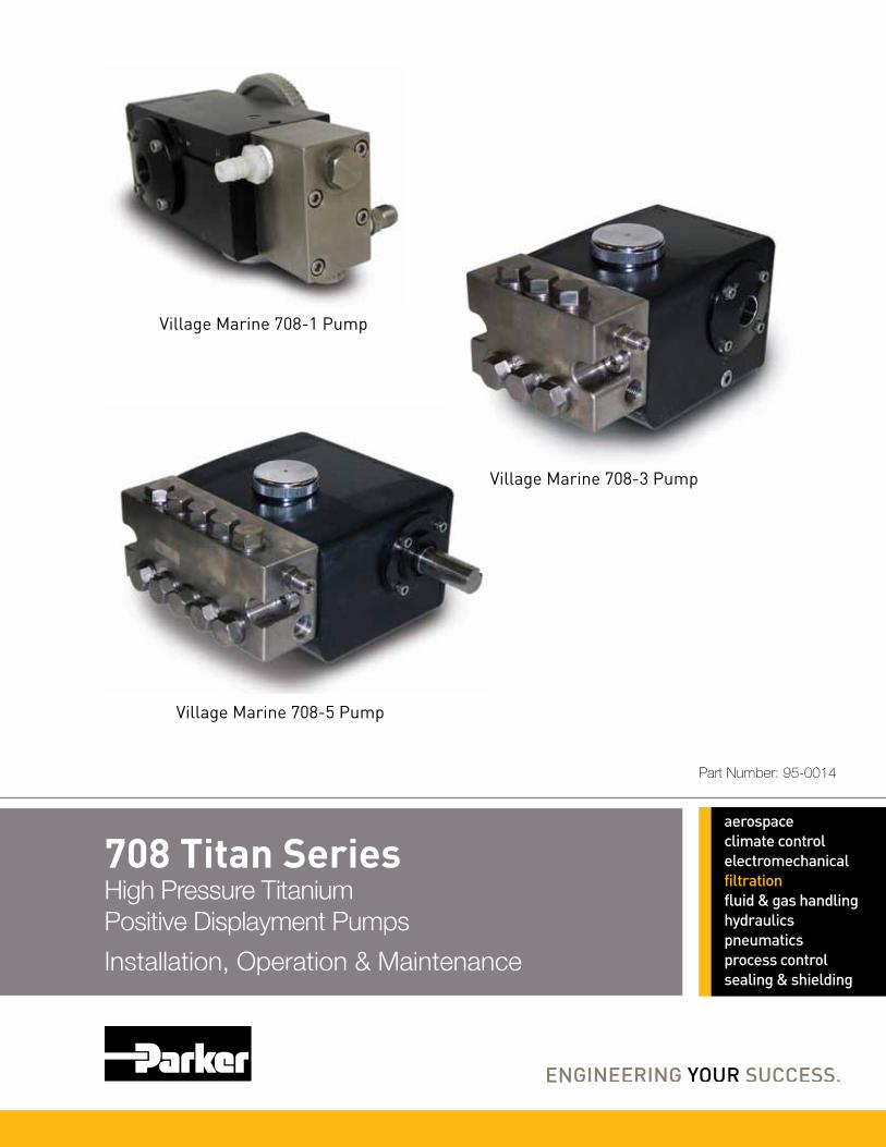
708 Titan SeriesHigh Pressure Titanium Positive Displayment Pumps
Installation, Operation & Maintenance
Village Marine 708-5 Pump
Part Number: 95-0014
Village Marine 708-3 Pump
Village Marine 708-1 Pump

TABLE OF CONTENTS INTRODUCTION..................................................................................................................................................................... 1 INITIAL START-UP INFORMATION...................................................................................................................................... 2
LUBRICATION .................................................................................................................................................................... 2 PUMP FLOW DESIGN........................................................................................................................................................ 2 MOTOR SELECTION.......................................................................................................................................................... 3 MOUNTING THE PUMP ..................................................................................................................................................... 3 DISCHARGE PLUMBING ................................................................................................................................................... 4 PUMPED FLUIDS ............................................................................................................................................................... 4
INLET CONDITION CHECKLIST........................................................................................................................................... 5 INLET SUPPLY ................................................................................................................................................................... 5 INLET LINE SIZE ................................................................................................................................................................ 5 INLET PRESSURE.............................................................................................................................................................. 5 INLET ACCESSORIES ....................................................................................................................................................... 6
PREVENTIVE MAINTENANCE SCHEDULE......................................................................................................................... 7 MAINTENANCE RECORD..................................................................................................................................................... 8 TROUBLESHOOTING............................................................................................................................................................ 9 SERVICE............................................................................................................................................................................... 12
INTRODUCTION ............................................................................................................................................................... 12 TOOLS NEEDED (VERIFY TOOL LIST) .......................................................................................................................... 12 DETACHING THE MANIFOLD FROM THE CRANKCASE .............................................................................................. 13
ROUTINE SERVICE KIT ...................................................................................................................................................... 13 VALVE ASSEMBLY ROUTINE SERVICE ........................................................................................................................ 13 MANIFOLD SEAL ROUTINE SERVICE............................................................................................................................ 14 CRANKCASE SEAL ROUTINE SERVICE........................................................................................................................ 15
SERVICING THE CRANKCASE .......................................................................................................................................... 15 OIL DRAIN PLUG O-RING REPLACEMENT.................................................................................................................... 17 PLUNGER ROD SEAL REPLACEMENT.......................................................................................................................... 17 BEARING SIDE PLATE O-RING/SEAL REPLACEMENT................................................................................................ 18 CRANKCASE COVER O-RING REPLACEMENT ............................................................................................................ 19 CRANKSHAFT BEARING, CONNECTING ROD-PISTON ASSEMBLY SERVICE ......................................................... 20
SERVICING THE MANIFOLD .............................................................................................................................................. 20 INLET/DISCHARGE ADAPTER O-RING REPLACEMENT 708-3 & 708-5...................................................................... 21 VALVE ASSEMBLY SERVICING...................................................................................................................................... 21 MANIFOLD SEAL SERVICING......................................................................................................................................... 23 ATTACHING THE MANIFOLD TO THE CRANKCASE .................................................................................................... 24


LIST OF FIGURES Fig. 1: Oil Level Sight Glass Detail. ..........................................................................................................................................................2 Fig. 2: Manifold Assembly Removal .......................................................................................................................................................13 Fig. 3: Valve Assembly............................................................................................................................................................................14 Fig. 4: Orientation for Manifold Seal Servicing ......................................................................................................................................15 Fig. 5: Plunger Retaining Bolt Assembly ................................................................................................................................................16 Fig. 6: Seal Retainer.................................................................................................................................................................................16 Fig. 5: Plunger Retaining Bolt Assembly ................................................................................................................................................18 Fig. 6: Seal Retainer.................................................................................................................................................................................18 Fig. 7: Manifold Assembly ......................................................................................................................................................................21 Fig. 8: Valve Assembly............................................................................................................................................................................22 Fig. 9: Orientation for Manifold Seal Servicing ......................................................................................................................................23 Fig. 10: Weep Ring Extraction ...............................................................................................................................................................24

LIST OF TABLES Table 1: Approximate Horsepower Required.......................................................................................................................... 3 Table 2: Tool List For Pump Service..................................................................................................................................... 12

1
INTRODUCTION Aqua Pro Pumps “708 Series” High Pressure Pumps are the product of our years of experience in the water treatment industry, and have been specifically designed and engineered for corrosive and high-pressure applications. Your new Aqua Pro Pump is made with dependable and proven technology to meet your highest demands. SPECIFICATIONS Specifications subject to change without notice. Pump type: Reciprocating Plunger
Oil Type: Village Marine Tec. High Pressure Pump Oil
(Part No. 85-0050-quart size) Maximum Inlet pressure: Flooded to 60 PSI Maximum Fluid Temperature: 120 degrees Fahrenheit (82 degrees Celsius)
Model Number Capacity Inlet Port
Size Discharge Port
Size Dimensions
L x W x H Weight Shaft
708-1 15 GPH .50 NPT .25 NPT 9.125”x 5.5” x 4” 11 lbs. ∅.625708-1 22 GPH .50 NPT .25 NPT 9.125”x 5.5” x 4” 11 lbs. ∅.625708-1 29 GPH .50 NPT .25 NPT 9.125”x 5.5” x 4” 11 lbs. ∅.625708-3 2.3 GPM .75 NPT .5” MS16142-8 7.5”x 6” x 4.5” 18.9 lbs. ∅.650708-3 3.5 GPM .75 NPT .5” MS16142-8 7.5”x 6” x 4.5” 18.9 lbs. ∅.650708-5 8 GPM .75 NPT .5” MS16142-8 11.5”x 9.5” x 5.5” 27.6 lbs. ∅.938
708-1 (15 GPH)
708-1 (22 GPH)
708-1 (29 GPH)
708-3 (2.3 GPM)
708-3 (3.5 GPM)
708-5 (8 GPM)
Number of Plungers: 1 1 1 3 3 5 Bore: .707” .707” .707” .707” .707” .707” Stroke: .2” .3” .4” .276” .512” .625” Oil Capacity: 6 oz 6 oz 6 oz 19.5 oz 19.5 oz 32 oz

708 Series High Pressure Titanium Positive Displacement Pump
2
(2.1) RPM Desired""GPM Desired""
RPM RatedGPM Rated :RPM Pump Desired =
INITIAL START-UP INFORMATION
The performance of the pump depends on the entire fluid system and will operate best with the proper installation of plumbing, operation, and maintenance of the pump.
LUBRICATION It is recommended that pump be filled with Village Marine Tec’s specially blended high pressure pump oil. To check the oil level, ensure the pump has stopped running. Then look into the sight glass in the side cover. Oil level should be level with the mark on the sight glass (Fig.1).
Fig. 1: Oil Level Sight Glass Detail.
PUMP FLOW DESIGN To drive the pump to give the desired discharge volume for your specific application equation 2.1 is to be used. PULLEY SELECTION It is essential that an appropriate pulley size be selected to meet your application needs. Based on the required pump discharge volume (in GPM), the correct pulley size can be selected using equation 2.2.
WARNING
This is a positive displacement pump. A properly designed pressure relief safety valve must be installed in the discharge piping. Failure to install such a relief mechanism could result in personal injury or damage to the pump or system. Aqua Pro Pumps does not assume any liability or responsibility for the operation of a customer’s high-pressure system.
NOTE
Change the original oil that came in the pump after running the pump for 100 hours. After the initial oil change, the oil should be changed at 500-hour service intervals.

3
MOTOR SELECTION To ensure desired pump output, the motor or engine driving the pump must possess sufficient horsepower to maintain full RPM when the pump is under load. Using equation 2.3 an appropriate electric motor can be sized for the application. This motor sizing approach is based on pump discharge volume and maximum pump discharge pressure. The constant in the equation accounts for drive and system losses, which implies a mechanical efficiency of 85%. Consult the manufacturer of a gas or diesel engine for selection of the proper engine size. Refer to Table 1 for sample horsepower applications.
(2.3) HP BrakeElectric 1460
PSI GPM :Required HP =×
Table 1: Approximate Horsepower Required HP Required (708-1 – 15 GPH) Working Pressure [PSI]Flow [GPH] Speed [RPM] 800 1000
15 734 .14 .17 14 686 .13 .16 13 637 .12 .15 12 588 .11 .14
HP Required (708-1 – 22 GPH) Working Pressure [PSI]Flow [GPH] Speed [RPM] 800 1000
22 718 .20 .25 21 686 .19 .24 20 653 .18 .23 19 620 .17 .22
HP Required (708-1 – 29 GPH) Working Pressure [PSI]Flow [GPH] Speed [RPM] 800 1000
29 710 .26 .33 28 686 .26 .32 27 661 .25 .31 16 637 .24 .30
HP Required (708-3 – 2.3 GPM) Working Pressure [PSI]Flow [GPM] Speed [RPM] 800 1000
2.5 1774 1.37 1.71 2.3 1632 1.26 1.58 2.0 1419 1.10 1.37 1.5 1064 .82 1.03
HP Required (708-3 – 3.5 GPM) Working Pressure [PSI]Flow [GPM] Speed [RPM] 800 1000
4 1530 2.19 2.74 3.5 1339 1.92 2.40 3 1148 1.64 2.05 2 765 1.10 1.37
HP Required (708-5 – 8 GPH) Working Pressure [PSI]Flow [GPM] Speed [RPM] 800 1000
8 1504 4.38 5.48 7 1316 3.84 4.79 6 1128 3.29 4.11 5 940 2.74 3.42
MOUNTING THE PUMP The pump should be located as close to the source of supply as possible. Mount the pump on a rigid, horizontal surface allowing easy access for crankcase oil draining. The pump should also be mounted in such a way that inspection can be done with ease. Ensure drive belt is adequately sized for system and shaft bearings. Pulley alignment is critical to the proper operation of the system. To check for proper alignment, place a straight-edge, square, or rule against the pulleys to make sure they
CAUTION
Pulley should be sized to not exceed the maximum pump RPM rating.
(2.2) RPM Motor
O.D.Pulley PumpRPM Pump
O.D.Pulley Motor :SizePulley =

708 Series High Pressure Titanium Positive Displacement Pump
4
are in line. Proper alignment of the drive pulleys will minimize crankshaft bearing and belt wear. Over tensioning of the drive belt may cause pump crankshaft bearing damage. If the pump will be in service in an environment with a high debris presence or in a humid environment, it is recommended that the pump be enclosed. Do not store or operate in excessively high temperature areas without proper ventilation.
DISCHARGE PLUMBING
In installations utilizing a Pulsation Dampening device, the device should be mounted directly to the discharge line. Consult dampening device manufacture for optimum pre-charge. A reliable pressure gauge should be installed near the discharge outlet of the manifold. This is extremely important for adjusting pressure-regulating devices; and when appropriate, for sizing of the nozzle or restricting orifice. The pump is rated for a maximum pressure; this is the pressure measured at the discharge manifold of the pump. A pressure relief or unloader valve must be installed to prevent over-pressure in the event that the discharge or down-stream plumbing becomes restricted or is turned off. Severe damage to the pump will result if this condition occurs without a relief valve in the line.
On fittings not using o-ring seals, use PTFE liquid sparingly, or tape to connect accessories or plumbing. Do not wrap tape beyond the last thread to prevent tape from becoming lodged in the pump or accessories. This condition will cause a malfunction of the pump or system.
PUMPED FLUIDS Some fluids may require a flush between operations or before storing. For pumping fluids other than water, contact your supplier or Village Marine Tec.
STORAGE For extended storage or between uses in cold climates, drain all pumped fluids from pump and flush with antifreeze solution to prevent freezing and damage to the pump.
CAUTION
Start system with all valves open or with minimal flow restriction to avoid deadhead overpressure conditions and severe damage to the pump or system. Discharge regulating devices should be at minimum pressure setting at start-up.
CAUTION
FAILURE TO INSTALL A SAFETY RELIEF VALVE WILL VOID THE WARRANTY ON THE PUMP.
CAUTION
DO NOT RUN PUMP WITH FROZEN FLUID. DO NOT RUN PUMP DRY.

5
INLET CONDITION CHECKLIST Review this checklist before operation of system. It is critical that all factors are carefully considered and met.
INLET SUPPLY Inlet supply should be adequate to accommodate the maximum flow being delivered by the pump.
1. Open inlet valve and turn on supply to avoid starving the pump.
2. Avoid closed loop systems, especially with high temperature, ultra-high pressure or large volumes. Conditions vary with regulating/unloader valve.
3. Low vapor pressure fluids, such as solvents, require positive heads to assure adequate inlet supply.
4. Higher viscosity fluids require that the pump be flooded to 60 PSI to assure adequate inlet supply.
5. Higher temperature fluids tend to vaporize and require positive heads to assure adequate inlet supply.
6. When using an inlet supply reservoir, size it to provide adequate supply of fluid to accommodate 6-10 minutes retention time at the rated GPM (however, a combination of system factors can change this requirement). Provide adequate baffling in the tank to eliminate air bubbles and turbulence. Install diffusers on all return lines to the tank.
INLET LINE SIZE Inlet line size should be adequate to avoid starving the pump. Pump suction should never operate in a vacuum.
1. Line size must be sufficient to allow free flow of influent fluid at the pumping flow rate. Minimize the use of thick-walled fittings, tees, 90-degree elbows, or valves in the inlet line of the pump to reduce the risk of flow restriction, vacuum, and cavitation.
2. The inlet line MUST be a FLEXIBLE hose, NOT a rigid pipe, and REINFORCED ON SUCTION SYSTEMS to avoid collapsing.
3. The simpler the inlet plumbing, the less the potential for problems. It is recommended to keep the length, number of joints, and the number of inlet accessories to a minimum.
4. Use pipe sealant as appropriate to ensure airtight positive sealing pipe joints.
INLET PRESSURE Inlet pressure should be between flooded (zero) to 60 PSI.
1. High RPM, high temperatures, low vapor pressures, or high viscosity reduces inlet pressure. The pump may require a pressurized inlet to maintain adequate inlet supply.
CAUTION
DO NOT RUN PUMP DRY.

708 Series High Pressure Titanium Positive Displacement Pump
6
2. Optimum pump performance and service life is obtained with 20 PSI (1.4 BAR) inlet pressure. With adequate inlet plumbing, most pumps will perform with flooded suction. Maximum inlet pressure is 60 PSI (5 BAR).
3. After prolonged storage, the pump should be purged of air to facilitate priming. With the pump not running, disconnect the discharge port and allow fluid to pass through pump, then reconnect the discharge port.
INLET ACCESSORIES Inlet accessories are designed to protect against over pressurization, control inlet flow, contamination or temperature and provide ease of servicing.
1. An inlet/supply shut-off valve is recommended to facilitate maintenance.
2. A standpipe can be used in some applications to help maintain a positive head in the inlet line.
3. Inspect and clean the inlet filters on a regular schedule, if applicable.
4. A vacuum/pressure gauge should be installed to monitor the inlet pressure. A gauge should be mounted as close to the pump inlet as possible. Short term, intermittent cavitation will not register on a standard gauge.
5. All accessories should be sized to avoid restricting the inlet flow.
6. All accessories should be compatible with the solution being pumped to prevent premature failure or malfunction.

7
PREVENTIVE MAINTENANCE SCHEDULE The Required Maintenance Schedule specifies how often you should have your pump inspected and serviced. It is essential that your pump be serviced as scheduled to retain its high level of safety, dependability, and performance. Not performing these tasks could result in catastrophic failure.
TASKS DAILY WEEKLY FIRST 100 HRS.
EVERY 500 HRS.
EVERY 1500 HRS.
PLAN FOR
EVERY 3000 HRS.
EVERY 10000 HRS.
INSPECTION TASKS
Clean Filters* X
Water Leaks X
Oil Level X
Pulley X
Belts X
Inspect Plumbing X
SERVICE TASKS
Pump Oil X X
Routine Service Kit X
Crankcase Rebuild Kit X
Manifold Rebuild Kit X
Crankshaft Bearings X * If applicable for system

708 Series High Pressure Titanium Positive Displacement Pump
8
MAINTENANCE RECORD Keep record of all maintenance below to ensure maintenance is performed. Note trends and increase maintenance as necessary.
HOURS** RECOMMEND SERVICE ACTIONS / NOTES ACTUAL
HOURS SIGNATURE DATE
100 Oil
500 Oil
1000 Oil
1500 Service Kit, Oil
2000 Oil
2500 Oil
3000 Service Kit/Full Kit*, Oil
3500 Oil
4000 Oil
4500 Service Kit, Oil
5000 Oil
5500 Oil
6000 Service Kit/Full Kit*, Oil
6500 Oil
7000 Oil
7500 Service Kit, Oil
10000 Crankshaft Bearing, Oil *Replace HP seal only in case of failure (see low-pressure troubleshooting, pg.9). Hours are for reference only (for maintenance planning purposes). ** Oil changes are mandatory at the specified hour intervals.

9
TROUBLESHOOTING Use the troubleshooting table below. If problem persists, contact your dealer. PROBLEM PROBABLE CAUSE SOLUTION
Low Pressure Belt slippage Make sure the correct belt is used. If the correct belt is used and the belt is slipping, then tighten. Replace belt if worn.
Leaky discharge hose Check connections. Replace hose if worn or cracking.
Pressure gauge inoperative or not registering correctly.
Check pressure with new gauge and replace as needed.
Air leak in inlet plumbing Use PTFE liquid or tape to seal the threads. Make certain that the PTFE does not go beyond the last thread. Doing so may damage the pump.
Inlet suction strainer clogged or improperly sized
Clear the obstruction, or use adequate size for inlet pump connection and fluid being pumped.
Relief valve stuck, partially plugged or improperly sized
Clean and reset relief valve to system pressure and correct bypass. Check supply tank for contamination.
Worn or dirty valves Clean valve or replace with a rebuild kit.
Worn high-pressure seals; abrasives in pump fluid, severe cavitation; inadequate water supply; stressful inlet conditions.
Replace seals with manifold rebuild kit(not service kit). Install and maintain proper filter, check line size and flow available to pump
Pulsation pump runs extremely rough, pressure low
Faulty pulsation dampener (if a pulsation dampener has been installed.)
Check pre-charge. Check manufacturer’s literature on recommended pressure.
Restricted inlet, or air entering inlet plumbing
Be sure that inlet hose is the proper size. Check filters and clean as needed. Check fittings and use PTFE liquid or tape for airtight connection.
Valve or spring damage Clean or replace valve and spring, check inlet supply tank for contamination
Seal damage Replace seals with manifold rebuild kit(not service kit).
Slight water leakage from under the manifold
Possible condensation No fix needed.
Worn low pressure seals Replace seals with Manifold Service Kit (not Rebuild Kit), check inlet pressure and inspect ceramic plunger for damage.
Excessive oil leak between crankcase and pumping section
Worn crankcase oil seals Replace crankcase oil seals.

708 Series High Pressure Titanium Positive Displacement Pump
10
PROBLEM PROBABLE CAUSE SOLUTION
Oil leaking in the area of the crankshaft
Worn crankshaft oil seal Replace damaged oil seals. (Purchase crankcase rebuild kit, not service kit)
Bad bearing Replace bearing.
Cut or worn o-ring on bearing case
Replace o-ring on bearing case.
Water in crankcase Humid air condensing into water inside the crankcase
Change oil every three months or 300 hours
Worn or improperly installed crankcase oil seals
Replace seals; follow proper installation procedure.
Excessive water leaking through low pressure seals
Replace seals with manifold rebuild kit(not service kit).
Excessive play in the end of the crankshaft
Worn bearing Replace bearing.
Oil leaking in the rear portion of the crankcase
Damaged or improperly installed crankcase cover, crankcase cover o-ring, drain-plug, or drain-plug o-ring.
Replace crankcase cover o-ring or drain-plug o-ring.
Loud knocking noise in pump Pulley loose on crankshaft Check key and tighten setscrew.
Restricted Inlet Clear obstruction or replace valve.
Worn bearing, connecting rod or crankshaft.
Consult supplier for crankcase servicing.
Worn belts Replace belts.
Frequent or premature failure of the seals
Running pump dry NEVER RUN THE PUMP WITHOUT WATER.
Abrasive material in the fluid being pumped
Install proper filtration on pump inlet plumbing.
Excessive temperature of pumped fluid (120 degrees F max.)
Reduce fluid inlet temperature to specifications.

11
PROBLEM PROBABLE CAUSE SOLUTION
Strong surging at the inlet and low pressure
Foreign particles in the inlet or discharge valve or worn inlet or discharge valves
Check for smooth surfaces on inlet and discharge valve seats. If signs of wear or damage are present return to factory for service.
Check supply tank for contamination, regularly clean filter. Do not pump abrasive fluid.
Restricted fluid flow Check the Inlet Conditions Checklist.

708 Series High Pressure Titanium Positive Displacement Pump
12
SERVICE An authorized technician should perform all service.
Pump rebuild kits are available for seal overhauls. Contact your dealer for ordering information.
INTRODUCTION All tasks should be performed in a clean environment, free from dust and debris. It is imperative that utmost cleanliness be maintained during the rebuild of your Aqua Pro Pump. The numbers following the parts are call out numbers. They correspond to the parts on the drawings.
READ THE INSTRUCTIONS COMPLETELY BEFORE ATTEMPTING TO PERFORM ANY SERVICE. Before assembling any parts, clean all parts to make free of oil, grease, dirt, and lint. Use a lint free cloth to wipe any part of the pump.
TOOLS NEEDED Table 2: Tool List for Pump Service
3/16” Allen Wrench Phillips Head Screwdriver
1/4” Allen Wrench Pick
7/16" Socket/ Socket Wrench or Combination Wrench Snap Ring Pliers
9/16" Socket/ Socket Wrench or Combination Wrench Torque Wrench (220 in.-lb.)
1/2” Socket/ Socket Wrench or Combination Wrench Weep Ring Removal Tool (PN 91-3827)
3/4" Socket/ Socket Wrench or Combination Wrench Dead Blow Hammer
7/8" Socket/ Socket Wrench or Combination Wrench Flat Head Screwdriver
7/8" Combination Wrench
CAUTION
Ensure pump is disconnected from the motor or any driving devices. Service the pump in a clean, dirt-free environment.
NOTE
A light coating of Anti-Seize Lubricant (PN. 85-0094) should be applied on all threaded parts, unless otherwise stated. Only silicon grease (PN. 21-1122) should be used on all o-rings and seals. Use of any other type of grease may result in o-ring or seal failure.

13
DETACHING THE MANIFOLD FROM THE CRANKCASE You will need these tools and parts to do the following:
9/16” Socket/ Socket Wrench (for 708-5) 1/2” Socket/ Socket Wrench (for 708-3) 3/16” Allen Wrench (for 708-1) Dead Blow Hammer
Remove the two manifold bolts (58) with a 9/16” socket wrench for the 708-5, with a 1/2” socket wrench for the 708-3, or the 4 socket head bolts with the 3/16” Allen wrench for the 708-1. Loosen the manifold assembly by lightly tapping off the manifold using the dead blow hammer, as seen in Fig. 2. Tap the manifold from both sides to apply even force to the manifold. Failing to do so can result in damage to the Ceramic Plungers. Set the manifold assembly aside in a clean work area. If the manifold assembly locating dowel pins (53) fall out, reinsert them into the manifold alignment pin holes.
Fig. 2: Manifold Assembly Removal
ROUTINE SERVICE KIT The following are the part numbers for the 708 Series Routine Service Kits. 708-1 Routine Service Kit (PN. 70-6181). 708-3, 2.3 Routine Service Kit (PN. 70-6182). 708-3, 3.5 Routine Service Kit (PN. 70-6183). 708-5 Routine Service Kit (PN. 70-6184). The Manifold Assembly must be detached from the crankcase to do the following service.
VALVE ASSEMBLY ROUTINE SERVICE You will need these tools and parts to do the following:
7/8" Socket Wrench or Combination Wrench Pick Spring, Valve (45): PN. 70-6003 Valve, Standard, 708 Series (44): PN. 70-6093 (For 708-1 & 708-3 2.3) Assembly, Valve, Heavy Duty, 708 Series (44): PN. 70-6104 (For 708-3 3.5 & 708-5) O-Ring, Valve Plug (46): PN. 70-6002 Silicone Grease Lubricant: PN. 21-1122 Anti-Seize Lubricant: PN. 85-0094 Lint-Free Cloths

708 Series High Pressure Titanium Positive Displacement Pump
14
When the manifold assembly has been removed from the crankcase assembly, place the assembly on a clean work surface. Remove all of the valve plug assemblies from the manifold assembly using a 7/8” socket wrench or combination wrench. Remove the valve (44) from the assembly, followed by the valve spring (45). With the aide of a pick remove the o-ring (46) from the valve plug.
Clean and inspect all valve plugs (47) prior to reassembling. If there is a problem, contact your dealer. Once all valve plugs (47) are clean and dry, install new valve plug o-ring (46) onto valve plug (47). Install the valve spring (45) onto the valve plug (47), it should now be attached to the plug. Press the valve (44) onto the valve spring (45). Complete valve assembly shown in Fig. 3.
Fig. 3: Valve Assembly
(NOTE: There are two different valve plug designs)
Inspect the manifold (38) for debris or other fouling and clean if necessary. Inspect the valve seat surface in the manifold. If there is a problem contact your dealer. Reinstall all the valve plug assemblies with a 7/8" socket wrench or combination wrench and tighten.
MANIFOLD SEAL ROUTINE SERVICE
You will need these tools and parts to do the following:
Flat screw driver Seal, LP (45): PN. 70-6009 Silicone Grease Lubricant: PN. 21-1122 Lint-Free Cloths
NOTE
Valve plugs (47) will be reused.
A light coating of silicon grease (PN. 21-1122) should be used on all new o-rings and seals. Use of any other type of grease may result in o-ring or seal failure.
NOTE
A light coating of Anti-Seize Lubricant (PN. 85-0094) should be applied on all threaded parts, unless otherwise stated.
NOTE
Pump manifold assembly must be detached from the crankcase assembly to service the seals.

15
For manifold seal servicing purposes the manifold must be placed with the valve plugs sitting on a flat surface and the plunger bores facing upward. This will facilitate service technician access to the seals for removal and installation, as shown in Fig. 4.
Fig. 4: Orientation for Manifold Seal Servicing
With a flat screw driver remove the low-pressure seal (43). Ensure that the low-pressure seal spacer (39) was not accidentally removed when the low-pressure seal was removed and press in the new low-pressure seal (43).
CRANKCASE SEAL ROUTINE SERVICE Remove the seal retainer (29) and set aside. Remove the plunger retainer bolt (28) with a 7/16” wrench, set aside. There is no need to remove the plunger retainer washer (28) or plunger retainer o-rings (27) from the plunger retainer bolt (28). Remove the ceramic plunger (26). Remove the slinger (25) and the outer washer (6). With the aid of the pick remove the plunger rod oil seal (7) from the crankcase. Inspect the seal retainer washers (8) for damage, if none evident then reuse, if damage is evident consult the factory.
Insert new plunger rod oil seal (7) into crankcase making sure that the seal is fully seated, place outer washer (6) on seal. Place slinger (25) onto the plunger rod (9).
Slide ceramic plungers (26) onto plunger rod and insert the plunger retainer washer (28) into the plunger. Clean the plunger retaining bolt’s (29) threaded area. If they were removed replace the o-rings (27) onto the plunger retainer (29). Slide the plunger retaining washer (28) onto the plunger retainer (29).
A light coating of silicon grease (PN. 21-1122) should be used on all new o-rings and seals. Use of any other type of grease may result in o-ring or seal failure.
A light coating of silicon grease (PN. 21-1122) should be used on all new o-rings and seals. Use of any other type of grease may result in o-ring or seal failure.
NOTE
Examine the ceramic plungers (26) for cracks, heavy scoring, or unusual wear. If there is a problem, contact your dealer.

708 SeriesHigh Pressure Titanium Positive Displacement Pump
16
Fig. 5: Plunger Retaining Bolt Assembly
Apply Red Loctite # 262 to retainer bolt (29) threads. Reinstall the plunger retainer bolt (29) and torque to 100 in. lb. usinga 7/16”socket.
Apply Aqua Pro’s special Ceramic Lubricant (PN. 85-0087) to the ceramic plungers (26). Slide the seal retainer over theceramic plungers (26). Make sure that the flanged side is close proximity to the manifold assembly, and that hole isoriented downward ensuring that the seal retainer has adequate water drainage.
Fig. 6: Seal Retainer
Routine service is now complete.
NOTE
Be CAREFUL not to get the red loctite on any other components.

17
SERVICING THE CRANKCASE The following are the procedures for servicing the crankcase assembly using the 708-1 Crankcase Rebuild Kit (PN. 70-6113). 708-3 Crankcase Rebuild Kit (PN. 70-6112). 708-5 Crankcase Rebuild Kit (PN. 70-6107). The manifold assembly must be detached from the crankcase to do the following service.
OIL DRAIN PLUG O-RING REPLACEMENT You will need these tools and parts to do the following:
7/8” Socket/ Socket Wrench Pick O-Ring, Drain Plug (4): PN. 30-1286 Anti-Seize Lubricant: PN. 85-0094 Silicon Grease Lubricant: PN. 21-1122
Remove the oil drain plug with a 7/8” wrench and drain the crankcase oil. Clean the drain plug (5), remove the o-ring (4) with the aide of the pick if necessary. Replace with the new one supplied in the kit. Apply anti-seize lube to the threads of the drain plug (5) and reinstall.
PLUNGER ROD SEAL REPLACEMENT You will need these tools and parts to do the following:
7/16” Socket/ Socket Wrench Torque Wrench Seal, Oil, Plunger Rod (7): PN. 70-6018 Washer, Plunger Retainer (27): PN. 70-6035 O-Ring, Plunger Retainer (26): PN. 70-6012 Slinger Barrier (24): PN. 70-6015 Ceramic Lubricant: PN. 85-0087 Silicone Grease Lubricant: PN. 21-1122 Red Loctite # 262 Lint-free Cloths
Remove the seal retainer (29) and set aside. Remove the plunger retainer bolt (28) with a 7/16” wrench, set aside. Remove the plunger retainer washer (28) and remove the ceramic plunger (26). Remove the slinger (25) and the outer washer (6). With the aide of the pick remove the plunger rod oil seal (7) from the crankcase. Inspect the seal retainer washers (8) for damage, if none evident then reuse, if damage is evident consult the factory.
Insert new plunger rod oil seal (7) into crankcase making sure that the seal is fully seated, place outer washer (6) on seal. Place slinger (25) onto the plunger rod (9).
NOTE
A light coating of silicon grease (PN. 21-1122) should be used on all new o-rings and seals. Use of any other type of grease may result in o-ring or seal failure.

708 SeriesHigh Pressure Titanium Positive Displacement Pump
18
Slide ceramic plungers (26) onto plunger rod and insert the plunger retainer washer (28) into the plunger. Clean theplunger retaining bolts (29). With the aide of a pick, remove the plunger retainer o-ring (27). Replace the o-ring (27) withthe new one supplied in the kit as shown in Fig. 6. Slide the plunger retaining washer (28) onto the plunger retainer (29).
Fig. 5: Plunger Retaining Bolt Assembly
Apply Red Loctite # 262 to retainer bolt (29) threads. Reinstall the plunger retainer bolt (29) and torque to 100 in. lb. usinga 7/16”socket.
Apply Aqua Pro’s special Ceramic Lubricant (PN. 85-0087) to the ceramic plungers (26). Slide the seal retainer over theceramic plungers (26). Make sure that the flanged side is close proximity to the manifold assembly, and that hole isoriented downward ensuring that the seal retainer has adequate water drainage.
Fig. 6: Seal Retainer
BEARING SIDE PLATE O-RING/SEAL REPLACEMENT
You will need these tools and parts to do the following: 3/16" Allen Wrench Philips Head Screw Driver
NOTE
Examine the ceramic plungers (26) for cracks, heavy scoring, or unusual wear. If there is a problem, contact your dealer.
NOTE
Be CAREFUL not to get the red loctite on any other components.

19
Pick Seal, Oil, Crankshaft (18): PN. 70-6038 (708-1, 708-3) 70-6061 (708-5) O-Ring, Bearing Side Plate (15): PN. 70-6039 O-Ring, Sight Glass (22): 70-6082 Silicon Grease Lubricant: PN. 21-1122 Anti-Seize Lubricant: PN. 85-0094
Remove the 4 socket head cap screws (19) with a 3/16” Allen Wrench from each of bearing side plate (16), (17), this applies to the 708-1, 708-3 3.5 GPM, and the 708-5 pumps. With the aide of a pick remove the o-rings from the grooves, remove the crankshaft oil seal (18) from the pulley side bearing cap (17). For 708-3 2.3 GPM pumps with direct drive, uncouple the pump from the motor. Remove the 4 Philips head screws (36) holding the bell housing (34) to the pump. Now remove the bearing side plate (17), o-rings and seal can now be replaced. Remove the sight glass retainer (24) from the bearing side plate (16). With the aide of a pick remove the sight glass o-ring (22). Replace o-ring with the one provided in the kit.
Press new crankshaft oil seal (18) into pulley side bearing cap (17), Install o-ring (15) in o-ring groove on the crankshaft bearing caps (16), (17) and reinstall caps on pump.
Install the 4 socket head cap screws (19) onto each of the bearing side plates and tighten with a 1/4” Allen Wrench. This applies to the 708-1, 708-3 3.5 GPM, and the 708-5 pumps. For the 708-3 2.3 GPM pump, reinstall the bell housing (34) by installing the 4 Philips head screws (36).
CRANKCASE COVER O-RING REPLACEMENT In this procedure you will replace the o-rings on the crankcase cover as provided in the rebuild kit. You will need these tools and parts to do the following:
3/16” Allen Wrench Phillips Head Screwdriver Pick Silicone Grease Lubricant: PN. 21-1122 Red Loctite # 262 Anti-Seize Lubricant: PN. 85-0094
CAUTION
Crankshaft oil seal is press fit at the factory, care is to be exercised during removal so damage does not occur to sealing surface.
NOTE
A light coating of silicon grease (PN. 21-1122) should be used on all new o-rings and seals. Use of any other type of grease may result in o-ring or seal failure.
NOTE
A light coating of Anti-Seize Lubricant (PN. 85-0094) should be applied on all threaded parts, unless otherwise stated.

708 Series High Pressure Titanium Positive Displacement Pump
20
Unscrew the crankcase cover screws (19) with the 3/16” Allen wrench. With the aide of the pick remove the crankcase cover o-ring (20).
Install the new crankcase cover o-ring (20) provided with the rebuild kit.
Reinstall the crankcase cover and tighten the crankcase cover screws (19) with the 3/16” Allen wrench.
CRANKSHAFT BEARING, CONNECTING ROD-PISTON ASSEMBLY SERVICE It is recommended that any service to the crankshaft bearings (16) or to the connecting rod-piston assembly be done by the factory. Due to the high precision required only factory trained personnel are recommended for this service. Performing any maintenance other than rebuild and service kits voids the warranty if not performed by factory trained personnel.
SERVICING THE MANIFOLD The following are the procedures for servicing the crankcase assembly using the 708-1 Manifold Rebuild Kit (PN. 70-6079). 708-3 2.3 GPM Manifold Rebuild Kit (PN. 70-6110). 708-3 3.5 GPM Manifold Rebuild Kit (PN. 70-6111). 708-5 Manifold Rebuild Kit (PN. 70-6105). 8 GPM Pump Manufactured After Feb 2002 708-5 Manifold Rebuild Kit (PN. 70-6108). 7 GPM Pump Manufactured Before Aug 2002 The manifold assembly must be detached from the crankcase to do the following service.
NOTE
A light coating of silicon grease (PN. 21-1122) should be used on all new o-rings and seals. Use of any other type of grease may result in o-ring or seal failure.
NOTE
A light coating of Anti-Seize Lubricant (PN. 85-0094) should be applied on all threaded parts, unless otherwise stated.
21
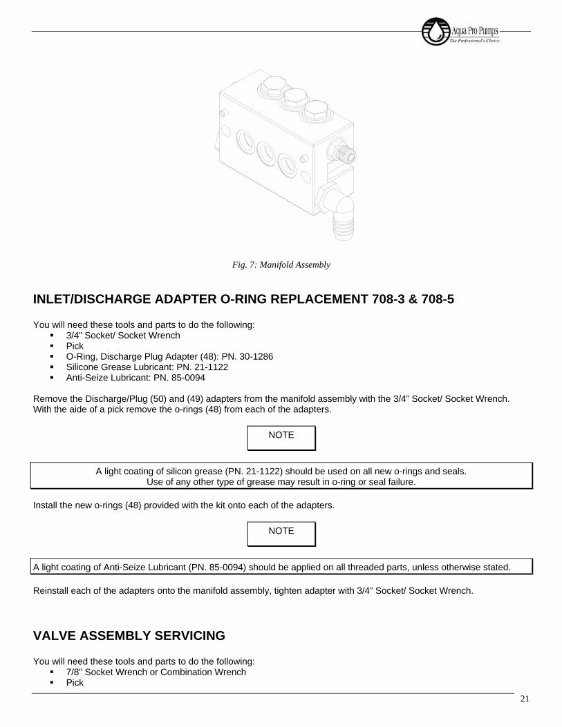
Fig. 7: Manifold Assembly
INLET/DISCHARGE ADAPTER O-RING REPLACEMENT 708-3 & 708-5 You will need these tools and parts to do the following:
3/4” Socket/ Socket Wrench Pick O-Ring, Discharge Plug Adapter (48): PN. 30-1286 Silicone Grease Lubricant: PN. 21-1122 Anti-Seize Lubricant: PN. 85-0094
Remove the Discharge/Plug (50) and (49) adapters from the manifold assembly with the 3/4” Socket/ Socket Wrench. With the aide of a pick remove the o-rings (48) from each of the adapters.
Install the new o-rings (48) provided with the kit onto each of the adapters.
Reinstall each of the adapters onto the manifold assembly, tighten adapter with 3/4” Socket/ Socket Wrench.
VALVE ASSEMBLY SERVICING You will need these tools and parts to do the following:
7/8" Socket Wrench or Combination Wrench Pick
NOTE
A light coating of silicon grease (PN. 21-1122) should be used on all new o-rings and seals. Use of any other type of grease may result in o-ring or seal failure.
NOTE
A light coating of Anti-Seize Lubricant (PN. 85-0094) should be applied on all threaded parts, unless otherwise stated.

708 Series High Pressure Titanium Positive Displacement Pump
22
Spring, Valve (45): PN. 70-6003 Valve (44): PN. 70-6093 O-Ring, Valve Plug (46): PN. 70-6002 Silicone Grease Lubricant: PN. 21-1122 Anti-Seize Lubricant: PN. 85-0094 Lint-Free Cloths
If manifold assembly has been removed from the crankcase assembly, place the assembly on a clean work surface. Remove all of the valve plug assemblies from the manifold assembly using a 7/8” socket wrench or combination wrench. Remove the valve (44) from the assembly, followed by the valve spring (45). With the aide of a pick remove the o-ring (46) from the valve plug.
Clean and inspect all valve plugs (47) prior to reassembly. If there is a problem, contact your dealer. Once all valve plugs (47) are clean and dry, install new valve plug o-ring (46) onto valve plug (47). Install the valve spring (45) onto the valve plug (47), it should now be attached to the plug. Press the valve (44) onto the valve spring (45). Complete valve assembly shown in Fig. 9.
Fig. 8: Valve Assembly
(NOTE: There are two different valve plug designs)
Inspect the manifold (38) for debris or other fouling and clean if necessary. Inspect the valve seat surface in the manifold. If there is a problem contact your dealer. Reinstall all the valve plug assemblies with a 7/8" socket wrench or combination wrench and tighten.
NOTE
Valves may be serviced while the manifold assembly is attached to the crankcase assembly.
NOTE
Valve plugs (47) will be reused.
A light coating of silicon grease (PN. 21-1122) should be used on all new o-rings and seals. Use of any other type of grease may result in o-ring or seal failure.
NOTE
A light coating of Anti-Seize Lubricant (PN. 85-0094) should be applied on all threaded parts, unless otherwise stated.

23
MANIFOLD SEAL SERVICING
You will need these tools and parts to do the following:
Snap Ring Pliers Tool, Weep Ring Puller, 708 Series: PN. 91-3827 Flat screw driver Seal, HP (40): PN. 70-0071 Ring, Snap (42): PN. 70-6010 Assembly, Weep Ring (41): PN. 70-3018 Seal, LP (43): PN. 70-6009 Silicone Grease Lubricant: PN. 21-1122 Lint-Free Cloths
For manifold seal servicing purposes the manifold must be placed with the valve plugs sitting on a flat surface and the plunger bores facing upward. This will facilitate service technician access to the seals for removal and installation, as shown in Fig. 10.
Fig. 9: Orientation for Manifold Seal Servicing With a flat screw driver remove the low-pressure seal (43). Manually remove the low-pressure seal spacer (39). With the snap ring pliers remove the snap ring (42). Using the weep ring extracting tool remove the weep ring assembly (41) as shown in Fig. 11.
NOTE
Pump manifold assembly must be detached from the crankcase assembly to service the seals.
NOTE
Extraction of the rings is accomplished by inserting tool in relaxed state into the inner diameter of the rings, then tighten the expansion bolt to grip the ring. Install the extraction stand and nut, tightening nut will extract to weep ring and isolating ring from manifold.

708 Series High Pressure Titanium Positive Displacement Pump
24
Fig. 10: Weep Ring Extraction With a flat screwdriver remove the high-pressure seals (40). Manually remove the high-pressure seal spacer (40). You must clean and inspect the following parts for re-use:
• Spacer, High-Pressure Seal (39): PN. 70-6016 • Spacer, Low-Pressure Seal (39): PN. 70-6016
Insert the high-pressure seal spacer (39) into the bore.
Insert the high-pressure seal (40) into the bore until the seal is fully seated on the high-pressure seal spacer (39). Insert the weep ring (41) into the bore after the installation of the high-pressure seals (39). Install the snap ring (42) using the snap ring pliers.
Insert the low-pressure seal spacer (39) and press in the new low-pressure seal (43). The manifold seal servicing is complete.
ATTACHING THE MANIFOLD TO THE CRANKCASE You will need these tools and parts to do the following:
9/16” Socket/ Socket Wrench (for 708-5) 1/2” Socket/ Socket Wrench (for 708-3) 3/16” Allen Wrench (for 708-1) Dead Blow Hammer Dead Blow Hammer Manifold Bolt (58): PN. 70-6055 (for 708-5) Manifold Bolt (58): PN. 70-6008 (for 708-3) Manifold Screw (58): PN. 70-6046 (for 708-1) Ceramic Lubricant: PN. 85-0087 Anti-Seize Lubricant: PN. 85-0094
NOTE
A light coating of silicon grease (PN. 21-1122) should be used on all new o-rings and seals. Use of any other type of grease may result in o-ring or seal failure.
NOTE
Ensure that the snap ring (42) is fully seated in the snap ring groove before continuing.

25
If a crankcase seal rebuild was not performed at this time then ensure that the dowel locating pins (53) are pressed into their corresponding hole. Ensure that ceramic lubricant is applied to the ceramic plunger assemblies and that the seal retainers are installed with the flange located away from the crankcase assembly.
Align manifold assembly to crankcase assembly and tighten the two manifold bolts (58) with a 9/16” socket wrench for the 708-5, with a 1/2” socket wrench for the 708-3, or the 4 socket head bolts with the 3/16” Allen wrench for the 708-1.
NOTE
A light coating of Anti-Seize Lubricant (PN. 85-0094) should be applied on all threaded parts, unless otherwise stated.

708 Series High Pressure Titanium Positive Displacement Pump
26

708-1 DRAWINGS

ABCD
12
67
887
65
43
21
SIZE
BTITLE
REV
B CHAIDEZ
DATE: 05-27-05
CSHEET 1 OF 3
ASSEMBLY, 708-1 M
AIN
54
D C B A
3
70
SHEETS 2 AND 3 HAVE BEEN REVISED
ADD PULLEY, SEE SHT 2
B
PER ECO-0031589: ADD NOTE 2; RENUMBER
ASSEMBLY, 708-1 M
ANIFOLD
1
C
TH TQD
-1
-ASSEMBLY, 708-1 CRANKCASE
TH TQD GA
1/10/2013
170-6129
--
ASSEMBLY, 708-1 CRANKCASE
11/15/12
PARTS LIST; REVISE P2, P3 - AS NOTED ON SHEETS
4/21/10
11
70
70-6131
ASSEMBLY, 708-1 CRANKCASE
-1
70
70-6130
ITEM
PART
NUMBER
DESCRIPTION
QTY
708-1
200 GPD
QTY
708-1
300 GPD
QTY
708-1
400 GPD
72
70-6046
SCREW, .25-20UNC-2A SHC X 2.50
44
4
71
70-6121
REVISIONS
REV.
DESCRIPTION
DATE
APPROVED
-INITIAL RELEASE
5/27/05
BC
A
32
1SHT
REVISION
STATUS OF
SHEETS
BC
CREV
72
71
70
2
NOTES:
1: ASSEMBLY PART NUMBERS ARE AS FOLLOWS:
70-6073 PUMP, 708-1, .200 CRANKSHAFT
70-6074 PUMP, 708-1, .300 CRANKSHAFT
70-6075 PUMP, 708-1, .400 CRANKSHAFT
2. APPLY A LAYER OF GRAPHITE ANTISEIZE 85-0094
ON THREADS OF ITEM # 72 BEFORE M
OUNTING.

37
39
39
39
39
39
37
12X TORQUE
3
10
14
54
21
20
34
19
17
18
15
31
26
2
13
87
6
25
27
30
28
29
16
22
23
24
9
11
1
27
32
33
TO 50 IN-LBS
TO 95 IN-LBS
2X TORQUE
TORQUE TO
55 IN-LBS
ABCD
12
67
887
65
4
B CHAIDEZ
21
SIZE
3
TITLE
4
BDATE: 05-26-05
CREV
ASSEMBLY, 708-1 CRANKCASE
5
SHEET 2 OF 3
D C B A
3
11
1-
170-6045
CRANKCASE,708-1,AL
11
1-
-
370-6030
CAP, OIL FILLER, PUMP, 708 SERIES
11
1-
-
270-6029
O-RING, OIL FILLER CAP
1
DENOTES THE OFFSET OF THE CRANKSHAFT STROKE. SEE DESCRIPTION FOR ITEM (12).
4) PUMP CRANKSHAFTS ARE STAMPED WITH A NUMBER 2, 3, OR 4 ON THE END THIS
70-6128 ASSY, DRIVE , 708 SERIES PUMPS
3) ITEMS 9,10 AND 11 MAY BE PURCHASE UNDER THE FOLLOWING PART NUMBER:
2) PART NUMBER 85-0087 AND 21-1122 ARE NOT SHOWN IN DRAWING
70-6181 KIT, ROUTINE SERVICE, 708-1
70-6113 KIT, REBUILD, CRANKCASE, 708-1
70-6131 ASSY, CRANKCASE, 708-1, .400 CRANKSHAFT
70-6130 ASSY, CRANKCASE, 708-1, .300 CRANKSHAFT
70-6129 ASSY, CRANKCASE, 708-1, .200 CRANKSHAFT
1) ASSEMBLY PART NUMBERS ARE AS FOLLOWS:
NOTES:
ITEM
PART
NUMBER
DESCRIPTION
QTY .200
STROKE
(70-6129)
QTY .300
STROKE
(70-6130)
QTY .400
STROKE
(70-6131)
QTY
REBUILD
KIT
(70-6113)
QTY
SERVICE
KIT
(70-6181)
39
21-1122
SILICONE GREASE
--
--
1
38
85-0087
ANTISIEZE, NM.91
--
-1
1
37
90-0225
LOCKTITE 262, THREAD LOCKER
AR
AR
AR
--
36
-NOT USED
--
--
-
35
-NOT USED
--
--
-
34
70-6050
CRANKSHAFT,708-1,.200
1-
--
-
33
70-0597
PULLEY
11
1-
-
32
70-0031
SPACER,CRANKSHAFT,708-1
22
2-
-
31
30-1106
PLUG, CRANKCASE
22
2-
-
30
70-6014
RETAINER,SEAL,708-1/3 SERIES
11
11
-
29
70-6035
WASHER, PLUNGER RETAINER, 708 SERIES
1-
28
70-6011
BOLT, PLUNGER RETAINER, 708 SERIES
11
1-
-
27
70-6012
O-RING, PLUNGER RETAINER
22
22
-
26
70-6013
PLUNGER, 708 SERIES
11
1-
-
25
70-6015
SLINGER, PLUNGER, 708 SERIES
11
1-
-
24
70-6043
RETAINER, SIGHTGLASS
11
1-
-
23
70-6044
SIGHTGLASS, OIL
11
1-
-
22
70-6082
O-RING, OIL SIGHTGLASS
11
11
-
21
70-6049
COVER, CRANKCASE, 708-1
11
1-
-
20
70-6048
O-RING, REAR COVER, 708-1
11
11
-
19
86-0151
CAPSCREW, SKT HD, .25-20UNC-2A, .75, 316 CRES
12
12
12
--
18
70-6038
SEAL, OIL, CRANKSHAFT, 708-1/3
11
11
-
17
70-6041
CAP, PULLEY BEARING, 708 SERIES
11
1-
-
16
70-6042
CAP, GUIDE BEARING, 708 SERIES
11
1-
-
15
70-6039
O-RING, BEARING CAP
22
22
-
14
70-6037
BEARING, CRANKSHAFT, 708-1/3
22
2-
-
13
70-1281
RING, SNAP, 708 SERIES
22
2-
-
12
70-6052
CRANKSHAFT, 708-1, 29 GPH (.4" STROKE)
--
1-
-
12
70-6051
CRANKSHAFT, 708-1, 22 GPH (.3" STROKE)
-1
--
-
11
70-6033
ASSY, CONNECTING ROD, 708 SERIES
11
1-
-
10
70-0382
PIN, DOWEL, M9, 22, STL
1
970-6067
PLUNGER, 708 SERIES
11
1-
-
870-6019
WASHER, OIL SEAL, INNER, 708 SERIES
11
1-
-
770-6018
SEAL, OIL, 708 SERIES
11
11
1
670-6017
WASHER, OIL SEAL, OUTER, 708 SERIES
11
1-
-
570-0696
PLUG, MS18829-08
11
1-
-
430-1286
O-RING, PLUG, OIL DRAIN
11
11
-
REVISIONS
REV.
DESCRIPTION
DATE
APPROVED
-INITIAL RELEASE
5/26/05
BC
AMODIFIED BOM QTY TITLE, NOTE INCLUDES ITEMS NOT IN
BOM TABLE
3/26/10
CC
BADD ITEM 32 & 33, PART 34 WAS PART 37
ADD PART 33 TO SHEET 2
11/15/12
TH TQD
CPER ECO-0031589: ADD ITEM 37 - THREAD LOCKER:
ADD ITEMS 37 & 39 BALLOONS; ADD: TORQUES
1/10/13TH TQD GA

56
50
57
57
55
59
5153
54
51
63
58
60
62
55
52
56
4
58
54
D C B AABCD
12
67
887
65
43
21
SIZE
BTITLE
REV
B CHAIDEZ
DATE: 05-27-05
BSHEET 3 OF 3
ASSEMBLY, 708-1 MANIFOLD
3
RING, SPACER, SEAL, 708 SERIES
70-6016
51
-1
NOTES:
70-6181 KIT, SERVICE KIT, 708-1
1) ASSEMBLY PART NUMBERS ARE AS FOLLOWS:
2
70-6079 KIT, REBUILD, MANIFOLD, 708-1
1SEAL, HP, 708 SERIES
--
3 APPLY A THIN LAYER OF SILICONE GREASE ITEM 65 (21-0022) TO ALL O-RINGS.
4 APPLY A LAYER OF GRAPHITE ANTISEIZE ITEM 64 (OR P/N 90-0928) TO
ALL CONTACT THREADS OF ITEMS 58 & 60 BEFORE MOUNTING.
4
3
70-6121 ASSY, MANIFOLD, 708-1
50
70-6047
MANIFOLD, 708-1
1
4
-
3
PART NO. 8500087 AND 21-0022 ARE NOT SHOWN IN DRAWING.
2)
70-0071
2
ITEM
PART NUMBER
DESCRIPTION
QTY
(70-6121)
QTY
REBUILD
KIT
(70-6079)
QTY
SERVICE
KIT
(70-6181)
65
21-1122
SILICONE GREASE
-1
1
64
85-0094
ANTISIEZE, GRAPHITE, FOOD GRADE
--
1
63
70-3018
ASSY, WEEP RING, 708 SERIES
11
-
62
30-0453
ADAPTER, LP INLET, 708-1
1-
-
60
30-0946
ADAPTER, HP DISCHARGE, 708-1
1-
-
59
70-6087
PIN, MANIFOLD, 708 SERIES
2-
-
58
70-6001
PLUG,VALVE,STANDARD,708 SERIES
2-
-
57
70-6002
O-RING, OIL DRAIN/VALVE PLUG
22
2
56
70-6003
SPRING, VALVE, 708 SERIES
22
2
55
70-6093
VALVE, 708 SERIES
22
2
54
70-6009
SEAL, LP, 708 SERIES
11
1
53
70-6010
RING, SNAP, 708 SERIES
11
-
52
REVISIONS
REV.
DESCRIPTION
DATE
APPROVED
-INITIAL RELEASE
5/27/05
BC
AMODIFIED BOM QTY TITLE, NOTE INCLUDES ITEMS NOT IN BOM TABLE
3/26/10
CC
BPER ECO-0031589: DEL: NOTE 2; ADD: NOTES 3,4; RENUMBER P/LIST.
1/10/13
GH TQD GA

708-3 DRAWINGS

DATE: 03-14-05
REV B
ASSEMBLY, 708-3 M
AIN
5
SHEET 1 O
F 3
D C B AABCD
12
67
887
65
43
21
SIZE
BTITLE
4
J RODRIG
UEZ
3
SHEETS 2 A
ND 3 H
AVE BEEN REVISED
A
BC
3/14/05
B
70-6118
-
ASSEMBLY, 708-3 M
ANIFOLD
1
2
INITIA
L RELEASE
ECO-0031541 - RENUMBER P/L; ADD: NOTE 2 &
TORQUE INFO
1
81
1: ASSEMBLY PART N
UMBERS A
RE A
S FOLLOW
S:
4/21/10
NOTES:
-ASSEMBLY, 708-3 C
RANKCASE
70-6124
80
TH TD D
M
-
70-6072 PUMP, 708-3, 3.5 G
PM
170-6125
ASSEMBLY, 708-3 C
RANKCASE
1
2 APPLY A
LAYER O
F G
RAPHITE A
NTISEIZE 85-0094
1/31/13
70-6076 PUMP, 708-3, 2.3 G
PM, LEFT C
RANKSHAFT
70-6126 PUMP, 708-3, 2.3 G
PM, RIG
HT C
RANKSHAFT
80
-
ITEM
PART
NUMBER
DESCRIPTIO
NQTY
708-3
2.3 G
PM
QTY
708-3
3.5 G
PM
82
70-6008
BOLT, SHOULDER, MANIFOLD
22
81
70-6119
ASSEMBLY, 708-3 M
ANIFOLD
-
REVISIO
NS
REV
DESCRIPTIO
NDATE
APPROVED
32
1SHT
REVISIO
N
STATUS O
F
SHEETS
BB
BREV
80
82
81
2X TORQUE
TO 355 IN-LBS

ASSEMBLY, 708-3 CRANKCASE
5
SHEET 2 OF 3
D C B AABCD
12
67
887
65
43
21
SIZE
BTITLE
4
J RODRIGUEZ
DATE: 03-14-05
BREV
3
39
40
TORQUE TO
24
23
22
16
14
15
32
13
1
23
8
67
25
27
28
26
29
30
18
17
34
31
9
10
11
20
4
5
19
12
21
35
36
27
37
95 IN-LBS
50 IN-LBS
TORQUE TO
TORQUE TO
55 IN-LBS
-
70-6183 KIT,ROUTINE SERVICE,708-3,3.5
70-6182 KIT,ROUTINE SERVICE,708-3,2.3
70-6112 KIT,REBUILD,CRANKCASE,2.3/3.5 GPM
70-6125 ASSY,CRANKCASE,708-3,3.5 GPM
-
2
2) PART NUMBER 85-0087 AND 21-1122 ARE NOT SHOWN IN DRAWING
3) ITEMS 9, 10 AND 11 MAY BE PURCHASED UNDER THE FOLLOWING PART NUMBER.
1
70-6128 ASSY,DRIVE,708 SERIES PUMPS
-1
1CRANKCASE, 708-3
70-6020
NOTES:
1) ASSEMBLY PART NUMBERS ARE AS FOLLOWS:
70-6124 ASSY,CRANKCASE,708-3,2.3 GPM
70-6029O-RING, OIL FILLER CAP
11
1-
--
ITEM
PART
NUMBER
DESCRIPTION
QTY 2.3
GPM
(70-6124)
QTY 3.5
GPM
(70-6125)
QTY
REBUILD
KIT
(70-6112)
QTY2.3
SERVICE
KIT
(70-6182)
QTY3.5
SERVICE
KIT
(70-6183)
40
90-0223LOCKTITE 252, THREAD LOCKER
A/R
A/R
11
1
39
21-1122SILICONE GREASE
--
-1
1
38
85-0087ANTISIEZE NM-91
A/R
A/R
11
1
37
86-0151CAPSCREW, SKT HD, .25-20UNC-2A, .75,
316 CRES
4-
--
-
36
70-0159SCREW, BELL HOUSING
4-
--
-
35
70-0192WASHER, EXTERNAL TOOTH, BELL
HOUSING
4-
--
-
34
70-6040HOUSING, BELL, 708-3
1-
--
-
33
-NOT USED
--
--
-
32
30-0157PLUG, CRANKCASE, SIDE
11
--
-
31
30-1106PLUG, CRANKCASE
33
--
-
30
70-6014RETAINER,SEAL,708-1/3 SERIES
33
3-
-
29
70-6011BOLT, PLUNGER RETAINER, 708 SERIES
33
--
-
28
70-6035WASHER, PLUNGER RETAINER, 708
SERIES
3-
--
-
27
70-6012O-RING, PLUNGER RETAINER
66
6-
-
26
70-6013PLUNGER, 708 SERIES
33
--
-
25
70-6015SLINGER, PLUNGER, 708 SERIES
33
--
-
24
70-6043RETAINER, SIGHTGLASS
11
--
-
23
70-6044SIGHTGLASS, OIL
11
--
-
22
70-6082O-RING, OIL SIGHTGLASS
11
1-
-
21
70-6023COVER, CRANKCASE, 708-3
11
--
-
20
70-6022O-RING, REAR COVER, 708-3
11
1-
-
19
86-0151CAPSCREW, SKT HD, .25-20UNC-2A, .75,
316 CRES
812
--
-
18
70-6038SEAL, OIL, CRANKSHAFT, 708-1/3
11
1-
-
17
70-6041CAP, PULLEY BEARING, 708 SERIES
11
--
-
16
70-6042CAP, GUIDE BEARING, 708 SERIES
11
--
-
15
70-6039O-RING, BEARING CAP
22
2-
-
14
70-6037BEARING, CRANKSHAFT, 708-1/3
22
--
-
13
70-1281RING, SNAP, 708 SERIES
22
--
-
12
70-6031CRANKSHAFT, 708-3, 3.5 GPM
-1
--
-
12
70-6032CRANKSHAFT, 3 PLGR, 2.3 GP
1-
--
-
11
70-6033ASSY, CONNECTING ROD, 708 SERIES
33
--
-
10
70-0382PIN, DOWEL, DRIVE ASSY
33
--
-
970-6067PLUNGER, 708 SERIES
33
--
-
870-6019WASHER, OIL SEAL, INNER, 708 SERIES
33
--
-
770-6018SEAL, OIL, 708 SERIES
33
33
3
670-6017WASHER, OIL SEAL, OUTER, 708 SERIES
33
--
-
570-0696PLUG, MS18829-08
11
--
-
430-1286O-RING, PLUG, OIL DRAIN
11
1-
-
370-6030CAP, OIL FILLER, PUMP, 708 SERIES
11
--
REVISIONS
REV.
DESCRIPTION
DATE
APPROVED
-INITIAL RELEASE
3/14/05
BC
AMODIFIED BOM QTY TITLE, NOTE INCLUDES ITEMS NOT IN BOM TABLE
3/26/10
CC
BECO-0031541 - RENUMBER PARTS 37, 38, 39; ADD: #40, BALLOONS & TORQUES
1/31/13
TH TD DM

ASSEMBLY, 708-3 MANIFOLD
5
SHEET 3 OF 3
D C B AABCD
12
67
887
65
43
21
SIZE
BTITLE
4
J RODRIGUEZ
DATE: 03-14-05
BREV
3
70-6183 KIT, ROUTINE SERVICE, 708-3,3.5
70-6182 KIT, ROUTINE SERVICE, 708-3,2.3
70-6111 KIT, REBUILD, MANIFOLD, 708-3, 3.5 GPM
70-6110 KIT, REBUILD, MANIFOLD, 708-3, 2.3 GPM
70-6119 ASSY, MANIFOLD, 708-3, 3.5 GPM
70-6118 ASSY, MANIFOLD, 708-3, 2.3 GPM
1) ASSEMBLY PART NUMBERS ARE AS FOLLOWS:
NOTES:
-
150
70-6000MANIFOLD, 708 SERIES, 3 PLUNGER
1
70-6016
51
--
--
--
2 APPLY A THIN LAYER OF SILICONE GREASE,
P/N 21-1122, TO
ALL O-RINGS.
3 APPLY A LAYER OF GRAPHITE ANTI SEIZE,
P/N 85-0094 TO ALL THREADS.
3
RING, SPACER, SEAL, 708 SERIES
66
66
-
ITEM
PART
NUMBER
DESCRIPTION
QTY 3.5
GPM
(70-6119)
QTY 2.3
GPM
(70-6118)
QTY3.5
REBUILD
KIT
(70-6111)
QTY2.3
REBUILD
KIT
(70-6110)
QTY3.5
SERVICE
KIT
(70-6183)
QTY2.3
SERVICE
KIT
(70-6182)
67
21-1122SILICONE GREASE
--
11
11
66
85-0094ANTISIEZE, GRAPHITE FOOD GRADE
--
--
11
65
70-6087PIN, MANIFOLD, 708 SERIES
22
--
--
64
30-0441ADAPTER, LP INLET, 708-3/5
11
--
--
63
30-0573PLUG, LP INLET, 708-3/5
11
--
--
62
30-1082ADAPTER, HP DISCHARGE, 708 SERIES
11
--
--
61
30-1286O-RING, PLUG, OIL DRAIN
22
22
--
60
70-6001PLUG, VALVE, 708 SERIES
-6
--
--
60
70-0660PLUG, VALVE, HD, 708 SERIES
6-
--
--
59
70-6002O-RING, OIL DRAIN/VALVE PLUG
66
66
66
58
70-6003SPRING, VALVE, 708 SERIES
66
66
66
57
70-6009SEAL, LP, 708 SERIES
33
33
33
56
70-6096VALVE, STANDARD, 708 SERIES
-6
-6
-6
56
70-6104ASSY, VALVE, HVY DUTY, 708 SERIES
6-
6-
6-
55
70-3052PLUG, HP DISCHARGE, 708-3/5
11
--
--
54
70-6010RING, SNAP, 708 SERIES
33
33
--
53
70-3018ASSY, WEEP RING, 708 SERIES
33
33
--
52
70-0071SEAL, HP, 708 SERIES
33
3
REVISIONS
REV.
DESCRIPTION
DATE
APPROVED
-INITIAL RELEASE
3/14/05
BC
A
UPDATED BOM TABLE. 70-6104 IS
NOW 70-6096. 70-3018 IS NOW
70-6006. NOTE INCLUDES ITEMS
NOT IN BOME TABLE
3/29/10
CC
BECO-0031541 - RENUMBER P/L;
ADD NOTES 2 & 3; SHOW ITEM 55
1/31/13
TH TD DM
3
60
59
56
62
64
65
57
53
52
63
51
54
58
61
50
61
51
2
55
3
2
3
2
3

708-5 DRAWINGS

75
76
2X TORQUE TO
C
355 IN. LBS.
77
C
J RODRIGUEZ
TITLE
CSHEET 1 O
F 3
ASSEMBLY, 708-5 M
AIN
54
D C B AABCD
12
67
887
65
43
DATE: 03-14-05
1
SIZE
2
BREV
3
75
70-6127
ASSY, CRANKCASE, 708-5
70-6123
76
SPEC
2BOLT, .50-13UNC-2A, SHOULDER
NOTES:
1 1
70-6055
LOCTITE - RED
ANTI-SIEZE - 85-0094
LUBRICATION: VMT PUMP O
IL - 85-0050
MAX RPM - 1500
MAX INLET PRESSURE - 60 PSI
CAPACITY: FLOW RATE - 8 G
PM
ASSEMBLY, 708-5 M
ANIFOLD
1: ASSEMBLY PART NUMBERS ARE AS FOLLOWS:
70-6178 PUMP, 708-5, 8.0 G
PM
70-6097 PUMP, 708-5, 8.0 G
PM, LEFT CRANKSHAFT
ITEM NO.
PART
NUMBER
DESCRIPTION
QTY.
77
32
1SHT
REVISION
STATUS O
F
SHEETS
DC
CREV
REVISIO
NS
REV.
DESCRIPTIO
NDATE
APPROVED
-INITIAL RELEASE
3/14/05
BC
ASHEETS 2 AND 3 HAVE BEEN REVISED
4/21/10
CC
BADD: SPEC NOES
5/30/12
TH GA
CECO-0031312: ADD TORQUES - UPDATE EACH SHEET TO CURRENT
STANDARDS - RENUMBER CONFLICTING PARTS LISTS
1/25/13
TH TQD G
A

--
-1
MACHINE,70-6056
70-6056
1
-
-
2
--
70-6184 KIT, ROUTINE SERVICE, 708-5
2) PART NUMBERS 85-0087 AND 21-1122 ARE NOT SHOWN IN DRAWING
3) ITEMS 9, 10 AND 11 M
AY BE PURCHASED UNDER THE FOLLOWING PART NUMBER.
70-6128 ASSY, DRIVE, 708 SERIES PUMPS
CC
1CAP, OIL FILLER, PUMP, 708 SERIES
70-6030
3
-1
1O-RING, OIL FILLER C
AP
70-6029
NOTES:
1) ASSEMBLY PART NUMBERS ARE AS FOLLOWS:
70-6127 ASSY, CRANKCASE, 708-5, 8.0 G
PM
70-6107 KIT, REBUILD, CRANKCASE, 708-5
C
ITEM
PART
NUMBER
DESCRIPTION
QTY
(70-6127)
QTY
REBUILD
KIT
(70-6107)
QTY
SERVICE
KIT
(70-6184)
QTY
SERVICE
KIT
(70-6128)
39
21-1122
SILICONE G
REASE
-1
1-
38
85-0087
ANTISIEZE NM91
-1
1-
37
70-0412
SPACER, BEARING, PULLY SIDE, 708-5
1-
--
36
90-0225
LOCKTITE 262, TH
READ LOCKER
A/R
--
-
35
-NOT USED
--
--
34
-NOT USED
--
--
33
70-0311
BEARING, PULLEY, 708-5
1-
--
32
-NOT USED
--
--
31
30-1106
PLU
G, CRANKCASE
5-
--
30
70-6114
RETA
INER, SEAL, 708 SERIES
55
--
29
70-6011
BOLT, PLU
NGER RETA
INER, 708 SERIES
5-
--
28
70-6035
WASHER, PLU
NGER RETA
INER, 708 SERIES
5-
--
27
70-6012
O-RING, PLU
NGER RETA
INER
10
10
--
26
70-6013
PLU
NGER, 708 SERIES
5-
--
25
70-6015
SLINGER, PLU
NGER, 708 SERIES
5-
--
24
70-6043
RETA
INER, SIG
HTG
LASS
1-
--
23
70-6044
SIG
HTG
LASS, OIL
1-
--
22
70-6082
O-RING, OIL SIG
HTG
LASS
11
--
21
70-6057
COVER, CRANKCASE, 708-5
1-
-
20
70-6058
O-RING, REAR C
OVER, 708-5
11
--
19
86-0151
CAPSCREW, SKT HD, .25-20UNC-2A, .75,
316 C
RES
12
--
-
18
70-6061
SEAL, O
IL, CRANKSHAFT, 708-5
11
--
17
70-6041
CAP, PULLEY BEARING, 708 SERIES
1-
--
16
70-6042
CAP, GUIDE BEARING, 708 SERIES
1-
--
15
70-6039
O-RING, BEARING C
AP
22
--
14
70-6060
BEARING, GUIDE, 708-5
1-
--
13
70-1281
RING, SNAP, 708 SERIES
1-
--
12
70-6059
CRANKSHAFT, 708-5, 8 G
PM
1-
--
11
70-6033
ASSY, CONNECTING ROD, 708 SERIES
5-
-5
10
70-0382
PIN, DOWEL, DRIVE ASSY
5-
-5
970-6067
PLUNGER, 708 SERIES
5-
-5
870-6019
WASHER, OIL SEAL, INNER, 708 SERIES
5-
--
770-6018
SEAL, O
IL, 708 SERIES
55
5-
670-6017
WASHER, OIL SEAL, O
UTER, 708 SERIES
5-
--
570-0696
PLU
G, MS18829-08
1-
--
430-1286
O-RING, PLU
G, OIL DRAIN
11
--
REVISIONS
REV
DESCRIPTION
DATE
APPROVED
-INITIAL RELEASE
3/14/05
BC
AMODIFIED BOM Q
TY TITLE, NOTE INCLU
DES ITEM NOT IN BOM TABLE
3/30/10
CC
BUPATED BOM
10/29/10
CC
CECO-0031312: ADD: ITEM 36; ADD: NM91 TO ITEM 38; ADD: TO
RQUES
1/25/13
TH TQD G
A
5
REV
D C B AABCD
12
67
887
65
43
21
SIZE
BTITLE
SHEET 2 O
F 3
J RODRIGUEZ
DATE: 03-14-05
C
4
ASSY, CRANKCASE, 708-5
3
38
36
31
13
14
22
23
16
54
19
21
20
12
11
10
9
3
2
7
86
25
26
33
37
15
18
17
27
28
29
30
C
DWG # 70-6127
55 IN LBS
TORQUE TO
55 IN LBS
TORQUE TO
TORQUE TO
95 IN LBS
C
C
C

D
12
67
887
65
43
21
SIZE
BTITLE
4
J RODRIG
UEZ
DATE: 03-14-05
DREV
ASSEMBLY
, 708-5 M
ANIFOLD
5
SHEET 3 O
F 3
D C B AABC
3
70-0071
-
DRAW
ING
2)
ITEM 44 IS 70-6093 INSTEAD O
F 70-6104
-
5
5
51
55
-
RIN
G, SPACER, SEAL, 708 SERIES
3
3 APPLY
A THIN
LAYER O
F SILIC
ONE G
REASE (ITEM 68
-
4
1-
PRODUCTION C
UT IN
FEB-02
10
70-6123 A
SSY, MANIFOLD
, 708-5, 8.0 G
PM
SEAL, H
P, 708 SERIES
-5
4 APPLY
A LAYER O
F G
RAPHITE A
NTISEIZE 85-0094 (ITEM 65)
PART NUMBER 85-0087 A
ND 21-1122 A
RE N
OT SHOW
IN
70-6184 KIT, ROUTINE SERVIC
E, 708-5
NOTES:
10
52
10
7
0-6108 KIT, REBUILD, MANIFOLD
, 708-5, 7.0 G
PM M
ODEL
1) ASSEMBLY
PART NUMBERS A
RE A
S FOLLOW
S:
3
70-6053
70-6105 KIT, REBUILD, MANIFOLD
, 708-5, 8.0 G
PM M
ODEL
4
MANIFOLD
, 708 SERIES, 5 PLU
NGER
70-6016
5
(OR P/N
90-0928) TO
ALL THREADS O
F ITEMS #
59, 61, 62.
50
P/N
21-1122) TO
ALL O
-RIN
GS.
PRODUCTION C
UT OUT AUG-02
ITEM
PART
NUMBER
DESCRIPTION
QTY
(70-6123)
QTY
REBUILD
KIT
(70-6105)
QTY
REBUILD
KIT
(70-6108)
QTY
SERVIC
EKIT
(70-6184)
68
21-1122
SILIC
ONE G
REASE
-1
11
67
85-0094
ANTISIEZE, GRAPHITE, FOOD G
RADE
--
-1
66
70-3018
ASSY, W
EEP RIN
G, 708 SERIES
5-
-
65
85-0928
ANTISIEZE, GRAPHITE, FOOD G
RADE
A/R
--
-
64
-NOT USED
--
--
63
70-6087
PIN
, MANIFOLD
, 708 SERIES
2-
--
62
70-3052
PLU
G, HP D
ISCHARGE, 708-3/5
1-
--
61
30-1082
ADAPTE
R, HP D
ISCHARGE, 708 SERIES
1-
--
60
30-1286
O-RIN
G, PLU
G, OIL D
RAIN
22
2-
59
70-0660
PLU
G, VALV
E, HD, 708 SERIES
10
--
-
58
70-6002
O-RIN
G, OIL D
RAIN
/VALV
E PLU
G10
10
10
10
57
70-6003
SPRIN
G, VALV
E, 708 SERIES
10
10
10
10
56
70-6093
VALV
E, PUMP, STD
--
10
-
55
70-6104
ASSY, VALV
E, HVY D
UTY
, 708 SERIES
10
10
-10
54
70-6009
SEAL, LP, 708 SERIES
55
55
53
70-6010
RIN
G, SNAP, 708 SERIES
REVISIO
NS
REV
DESCRIPTION
DATE
APPROVED
-IN
ITIA
L RELE
ASE
3/1
4/0
5BC
AMODIFIED BOM Q
TY TITLE
, NOTE INCLU
DES ITEMS N
OT IN
BOM TABLE
3/3
0/1
0CC
BUPDATED BOM
10/2
9/1
0CC
CUPDATED BOM C
HANGED PC 54
11/2
3/1
0GG
DE
CO
-00
31
31
2:
RE
NU
MB
ER
P/L
;RE
VIS
E N
OT
ES
; C
LA
RIF
Y A
NT
ISE
IZE
AN
D S
ILIC
ON
E1/2
8/1
3TH
TQD G
A
57
59
58
55
61
63
52
66
51
53
54
60
62
50
60
51
56
OR