Embed Size (px)
DESCRIPTION
745i4 Install Manual Alarm system
Citation preview

INSTALLATIONINSTRUCTIONS
for models
COPYRIGHT 1999: OMEGA RESEARCH & DEVELOPMENT, INC.
328i4 / 533i4 / 745i4
In the views above, note the five terminals, or "pins". A relay's opera-tion is really very simple. To understand its operation, consider the relay ashaving two sections - the coil, pins 85 and 86; and the contacts, pins 30, 87and 87a. When Negative Ground is supplied to one end of the coil, andPositive Voltage is supplied at the other end, the coil creates a magnetic fieldwhich activates the relay. This magnetic field attracts the armature, which isattached to pin 30 with a flexible joint, just like a hinge. Inactivated, or "atrest", the armature connects pin 30 to pin 87a. When the relay is activated,the armature connects pin 30 to pin 87.
The terms used to describe the contact points are thus: pin 30 switchesbetween pins 87a and 87, so it is "Common" to both and is usually referredto as COM. In the relay's normal condition, at rest, pin 30 is connected to pin87a, making pin 87a "Normally Closed" or NC. Pin 87 is not connected to pin30 at rest, so its status is "Normally Open" or NO.
Universal Relay Wiring Instructions
85
A R
M A
T U
R E
85
A R
M A
T U
R E
30 30
At Rest(Coil Not Energized)
Activated(Coil Energized)
86C
O I
L
87a
86
C O
I L
87a8787
Footprint View
87
86 87a 85
30
This type of relay is defined as "SinglePole Double Throw" or SPDT. This termmeans that the single armature terminal (orpole, pin 30) can be connected (or "thrown")to two other terminals, pins 87a and 87. TheSPDT relay is one of the most useful con-figurations due to its flexibility - it can beused as a switching device, to isolate circuits,to interrupt circuits and to interrupt andswitch at the same time. For convenience,this booklet shows the relay’s “footprint”view in its diagrams.
MI_CG357i4

Installation ConsiderationsBefore Starting The Installation ........................................................ 4Mounting The Control Module ........................................................ 4Mounting The Electronic Siren ......................................................... 4-5Status Light and Valet Switch ........................................................... 5Otional Echo Status Light and Valet Switch ..................................... 5Auxiliary Sensor Port ........................................................................ 6-7
Main Power Connections - 5-Pin ConnectorBlack Wire (Ground) ......................................................................... 6Red Wire (Constant Power) ............................................................. 7Yellow Wire (Ignition Input) ............................................................ 7Orange Wire (Output While Armed) ................................................. 7-9Gray Wire (Auxiliary Output #2) ...................................................... 9
Secondary Connections - 8-Pin ConnectorBrown Wire (Positive Siren Output) ................................................9-10White Wire (Flashing Light Output) ................................................10-12Green Wire (Negative Door Trigger) ................................................12-13Violet Wire (Positive Door Trigger) ................................................. 14Blue Wire (Negative Instant Trigger) ...............................................14-15Pink Wire (Auxiliary Output #3) ...................................................... 15Black/Red & Green/Violet Wires (Dome Light Supervision) ............16-19Smart Trigger Feature ........................................................................16-19
Power Doorlock InterfacesBasic Types Of Power Doorlock Systems .........................................19-23Differences By Model ....................................................................... 24Doorlock Diagrams ...........................................................................25-34The Optional DLS-3 ..........................................................................35-36
Testing The System .......................................................................... 36Plug-In Backup Battery .....................................................................36-37Plug-In Port for Optional Pager ......................................................... 37Programming Transmitters ................................................................37-38Features Programming Checklist .......................................................38-39Universal Relay Wiring Instructions ..................................... Back Cover
Page - 39
Omega Disclaims Any Responsibility or Liability In Connection With Installation
#1 SecureCode Programming 1 Press (n/a)
#2 30 / 60 Second Activated Alarm Cycle 30 Seconds (U)
#3 3 / 45 Second Arming Delay 3 Seconds (L)
#4 Last Door Arming OFF (U)
#5 Automatic Rearming OFF (U)
#6 Auxiliary Output #2 Also Disarms System ON (L)
#7 Parking Light Illumination Upon Disarm ON (L)
#8 Doors Lock At Ignition “On” ON (L)
#9 Unlock #1 At Ignition OFF ON (L)
#10 Unlock #2 At Ignition OFF (not used on 328i4) OFF (U)
#11 Open Door Bypass To Features 8, 9, 10 ON (L)
#12 Doors Lock With Last Door Arming OFF (U)
#13 Doors Lock With Automatic Rearming OFF (U)
#14 Ignition-Activated Vehicle Recovery OFF (U)
#15 Door-Activated Vehicle Recovery OFF (U)
#16 Transmitter-Activated Vehicle Recovery OFF (U)
#17 Chirp Confirmation ON (L)
#18 Steady Siren or Pulsed Horn Output Steady Siren (U)
#19 Soft or Loud Horn Confirmation Chirps “Medium Loud” (:)
#20 1 or 2 Button Arming / Disarming 2 Button (U)
#21 Double Unlock Pulse OFF (U)
#22 Total Closure Lock Output OFF (U)
# FEATURE DEFAULT
The system will exit programming mode if 10 seconds expire without anyprogramming input, or if the ignition is turned “on”. Use the “quick checklist”of programmable features below, but carefully read the Operation Guide to fullyunderstand the features and the programming procedure.

This Installation Manual explains the installationand connect ion of these system's wir ingconnections utilizing the included UniversalHarness. Certain Omega Quick InterconnectHarnesses, which plug directly into the vehicle'sexisting wiring harnesses, are available. Specificinstructions are included with each QuickInterconnect Harness.
These instructions are for three Crime Guardmodels; the beginning of each section specifies“all models” or notes the exact model or models.
Instructions for programming transmitters andfeatures may be found in the Operation Manual.
Page - 3
Installation Considerations
Important: The single most important factor regarding the properoperation and effectiveness of a vehicle security system is its installation.This system can be successfully installed with basic hand tools, by care-fully following these instructions. One area to take special care in is wiringconnections; soldering is most desirable, with crimp-type terminals follow-ing. “Quick-tap” or “t-tap” connections are acceptable, providing that ex-treme care is taken to ensure that they are done correctly. The “strip andtwist” method of joining wires is the least desirable; although a satisfactoryconnection can be made if done properly, this is considered as the leastreliable method of joining wires. When using any method, it is most impor-tant that the spliced wires be adequately insulated; not only to preventshort-circuits, but to also protect the wires’ splice from exposure to theweakening environmental effects of moisture in the atmosphere.
Page - 38
The following is quick reference description of both the programmingprocedures for transmitters (including the optional echo 2-way controller),and the programming procedure for the system’s features. Please refer tothe Operation Guide for complete details of transmitters and features’ pro-gramming, as well for a description of the programmable features.
Programming ReferrenceAll Models
Step 4 Repeat the previous step for each transmitter or transceiver whichis to operate the system.
Step 3 Within 10 seconds press and release the Upper Left “Lock” Button(with the “locked padlock” icon). The siren will chirp once,confirming that the system learned the transmitter.
Step 2 Within 5 seconds of turning on the ignition, press the Valet Switch5 times. The siren will chirp once, confirming that the system isready to learn a transmitter.
Step 1 Turn the vehicle’s ignition key “on”.
The system will remove itself from the programming mode if 10 seconds expirewithout its receiving a signal, if the ignition is turned “off”, or upon fourtransmitters or transceivers being programmed into the system.
Have all of the transmitters or transceivers at hand(when one is programmed, all existing codes are erased).
Transmitters:
Features:Step 1 Turn the vehicle’s ignition key “on”, then “off”.
Step 3 After the siren chirps and sounds briefly, press the Valet Switch thesame number of times as the desired feature number.
Step 2 Press the Valet Switch 5 times.
Step 5 Repeat Steps 3 and 4 for each additional feature.
Step 4 Wait for the siren to confirm the same number in chirps, then pressthe transmitter’s Upper Left “Lock” Button to turn the feature on (1 chirp), orpress the Upper Right “Unlock” Button to turn the feature off (2 chirps).

Page - 4
Before Starting The Installation: This entire booklet shouldbe read before starting the installation. An understanding of which controlmodule wires are to be used and their functions is essential. Installationswill vary from car to car , as some control module wire connections arerequired, while others are optional. Before starting the installation, it shouldbe determined which control module wires will be used. Most installers willlist these wires, then "map out" the installation by locating and noting thetarget wires in the vehicle. This will also determine the best location for thesystem’s control module, which is mounted upon completion of the installa-tion and testing of the system.
Most of the main wiring harness connections will be made at the ignitionswitch harness, which is typically located around the steering column area.Caution! Avoid the Airbag circuit! Especially avoid any harness or wiresencased in Yellow or Red tubing or sleeves. Do not use a standard test light,as it can deploy an airbag or damage on-board computers and sensors if thewrong circuits are probed. Instead, use a Digital Multimeter (DMM). Properwiring connections are a must!
Mounting The Control Module: The Control Module con-tains the necessary electronics required for the system's operation. Alwaysmount this module in the vehicle's interior compartment, in a secure locationthat is not easily accessible. Ensure that moisture, vibration and tempera-ture extremes are minimized. Acceptable locations include mounting behindthe dash, behind the glovebox or other interior panels.
Mounting The Electronic Siren: Find a location in the en-gine compartment away from the extreme heat of the engine and manifold.Remember the “map out” approach to installation; the hood pin switch wireand any other wires to be ran to the engine compartment should be consid-ered. Route these wires very carefully to prevent their being damaged orshorted by being pinched, or by hot or moving parts of the vehicle. In manycases the vehicle may have an unused rubber grommet on the firewall; theseare excellent methods for routing wires to the engine compartment. Cut asmall slice in the rubber, pass the wires through the grommet (needle-nosepliers are good for this) and be sure to reinstall the grommet in firewall sheetmetal. If the vehicle is equipped with a speedometer cable, its grommettypically offers a path through the firewall. Always protect the wires whichare routed to the engine compartment; for example, if the siren Positive wire
Page - 37
Step 3Program the Echo transceiver and the original 1-way transmitters into thesecurity system (see the following page for programming instructions).
LED andValet Switch
plugs.
Echo BaseTransmitter/
Receiver Unit Host Omega SecuritySystem Control
Module
( ( (EC
HO
Step 2Plug in and route the Echo transmitter/receiver unit wiringharness. Using the adhesive tape, mount the Echo transmitter/receiver onto an interior glass (carefully clean the surface).
The Status Lights and Valet Switch in the receiver/transmitter utilize separateconnectors; if either, or both, are not be used, simply leave the original StatusLight or Valet Switch intact in the vehicle and plgged into the Crime guardcontrol module. A customized SecureCode is recommended when the Echo’sValet Switch is used.

Page - 5
is shorted to Ground, the control module can suffer serious damage.A suitable siren mounting location will offer a firm mounting surface, will
also allow sound dispersion out of the engine compartment, and not beaccessible to a thief. The siren must be pointed downward to avoid mois-ture collecting inside it and to enhance sound dispersal. Use three of theincluded screws to securely mount the siren.
LED Status Light and Valet Switch: This system includesa separate LED Status Light and Valet Switch. Also included is a combinationholder assembly for the LED Status Light and Valet Switch. Mount theassembly in a location where it can easily be seen by the driver, and preferablywhere it can be seen from outside, as the LED Status Light provides a levelof visual deterrence. Two mounting methods are provided: double-sidedadhesive tape, and two screws. If using the adhesive tape, properly preparethe mounting surfaces to ensure good adhesion. If using the screws for a morepermanent mounting, carefully separate the housing halves, install thescrews (avoid overtightening), then snap the assembly halves back together.Carefully route the wiring harness to the control module to avoid any chancesof it being chafed or pinched.
Or, the LED Status Light may be custom-mounted inside the vehicle bydrilling a 9 / 32” hole in a suitable interior panel; be sure to carefully ensurethat the area behind the location has unobstructed depth of at least 1/2”. route the wiring harness through the hole to the control module, and snapthe LED in place. Plug the LED’s small 2-pin plug into the Red matching porton the control module. Mount the valet switch, using its adhesive pad, in ahidden location which is accessible to the operator; carefully route the wiresto the control module, and plug the valet switch’s Blue 2-pin plug into thecontrol module’s Blue 2-pin port.
Optional Echo Status Light & Valet Switch: If theoptional Echo 2-way controller upgrade is utilized, it’s window-mountedtransceiver will contain an alternative LED and Valet Switch. These will pluginto the same ports on the control module as the stock items. Or, this kit’soriginal items may be utilized, and the Echo’s LED and Valet Switch not used.
Auxiliary Sensor Port: This allows the easy plug-in addition ofan auxiliary sensor. The auxiliary sensor port is dual-zoned: the first zone willrespond by chirping the siren only; and the second zone will respond by
Page - 36
The Optional Echo 2-WayController / Pager
All Models
The Crime Guard 328i4, 533i4 and 745i4 all feature a plug-in port for anoptional Omega 2-way Echo controller / pager, which is a great security andconvenience enhancement. Although the Echo comes complete with its ownoperation and installation instructions, operation instructions are also in-cluded in the Operation Guide, and installation instructions are included here.
Besides the Echo 2-way controller, this option consists of a separately-mounted base receiver/transmitter unit which is plugs directly into the CrimeGuard security system module; no other wiring connections are needed. Thebase receiver/transmitter unit may be mounted directly to an interior glass byutilizing the attached adhesive pad (clean and prepare the glass beforeadhering) for the best operating range. The receiver/transmitter also containsalternative system Status Lights and a Valet Switch. these may be used, orthe original items may be retained.
the connector into the system's smaller White port inside the case. Insert thebattery into the built-in battery compartment inside the control module, andclose the case.
Replacement 9 volt alkaline batteries can be purchased anywhere batter-ies are sold. It is recommended that the battery be replaced with anotheralkaline battery every 18 months or after the 9 volt battery has operated thesecurity system on its own for any length of time.
INSTALLATION: The Echo system consists of the 2-way controller unit,and in the vehicle a transmitter/receiver and wiring harness which connectsit to the Crime Guard system contol module.
Step 1Locate & Remove the securitysystem’s Echo port jumperconnector (it has a Red wire loop). Crime Guard
Control Module
V

fully triggering the system. These ports supply constant 12 volt power,grounded output when the system is armed, a negative instant trigger, anda negative prewarn trigger. The Crime Guard 745i4 features dual sensor ports,both having identical operation, easily facilitating multiple sensors.
The Crime Guard 533i4 and 745i4 include sensor units, which are packagedwith their own instruction sheet.
Main Power Connections -5-Pin Connector
Black Wire - (Ground): All ModelsThe Black wire provides Negative ground for the system; proper connec-
tion of this wire is important.CONNECTION: Using the correctly sized crimp-on ring terminal, con-
nect the Black wire to the metal frame of the vehicle, preferably using anexisting machine-threaded fastener. Make sure that the ring terminal attachedto the Black wire has contact with bright, clean metal. If necessary, scrapeany paint, rust or grease away from the connection point until the metal isbright and clean. If the control module has an insufficient ground connection,the security system can find partial ground through the wires that areconnected to other circuits, and function, but not correctly. As the alarm canpartially operate, a bad ground wire connection would not likely be sus-pected.
Antenna Wire - All ModelsThe Black (or Black/Red) wire attached to the control module is the
coaxial antenna cable. Do not connect this wire to anything or the transmitter'srange will be reduced or eliminated. Stretch the Black antenna wire out andas high as possible for the best operating range. If desired, this wire can beextended to possibly increase the unit’s operating range. The same size wireshould be used (22 ga.), and as a general rule the added length should notexceed twice the standard length.
Page - 6
Make all of the wiring connections, then plugboth of the harnesses into the control module.
Page - 35
doors, unlock only the driver's upon disarming (“driver's door priorityunlock”) and, if desired, a second press of the transmitter's large button within5 seconds will unlock all of the doors.
The DLS-3 used with two relays can be used in place of the DLS to lockand unlock all doors (“standard doorlocks”). Although the 328i4 does notfeature a driver door priority unlock output, the optional DLS-3 and two relayscan be used with the 328i4 to lock and unlock all of the vehicle’s doors.
Testing The SystemAll Models
Important: Upon completion of all wiring connections, the systemshould be tested for proper operation before the final mounting of the con-trol module. Most experienced installers prefer to make all wiring connec-tions, and then plugging in all of the wiring harness connectors to thecontrol module. Whenever the control module is first powered up, it willsound briefly, then revert to its last condition, typically the disarmed state.If the system was armed, or triggered when power and ground were lastremoved, then when next powered up, the system will be in the triggeredstate. Once the system is tested and found to operate properly, the backupbattery should be installed, the control module mounted, wiring harnessesneatened, and any removed vehicle’s interior parts reinstalled.
Plug-in Backup BatteryAll Models
All three Crime Guard models include a battery and plug-in harness for abackup battery circuit. This 9 volt alkaline battery is all that is required toprovide alternate power to operate the security system in the event that thevehicle's battery is disconnected, and a built-in protection circuit will notallow the 9 volt battery to feed back into the vehicle's electrical system.System operation while on backup battery power is described in the Opera-tion Guide.
To install the backup battery, always make the security system's Black andRed wire connections first. Remove the sliding panel on top of the controlmodule, snap the connector and harness onto the 9 volt battery and then plug

Page - 7
Red Wire - (Constant Power Input): All ModelsThe Red wire's function is to supply Constant Positive 12 Volts for
security system's operation. When 12 Volts is first applied to the Red wire,the system will revert to the state in which it was in when power was takenaway. If the vehicle to be serviced, especially if it involves the battery, thesystem should be placed in Valet Mode. This will prevent the system frombeing activated if the battery is disconnected and reconnected. The Red wirealso supplies 12 Volt Positive to the module's internal relay for flashing theparking lights.
CONNECTION: Connect the Red wire to a Constant Positive 12 Voltsource. This source should have Positive 12 Volts with at least a 15 Ampcapacity at all times and in all ignition key positions. Connection locationscan be at the supply wire at the ignition switch, the supply wire behind thefuse block or the fuse/junction block. Never just insert the Red wire or anyother security system wire behind a fuse. Also, please note that connectingdirectly to the battery's Positive terminal will expose this connection to failuredue to a corrosive environment unless the connection has a protectivecoating.
Yellow Wire - (Ignition Input): All ModelsThe Yellow wire is an ignition "on" input to the security system. This
connection is critical to the proper operation of many of the security system'sfeatures.
CONNECTION: This wire supplies Positive 12 Volts to the controlmodule whenever the ignition switch is "on". This connection should bemade at the ignition switch harness, to the primary ignition circuit. Primaryignition has 0 Volts when the ignition key is in the "Lock", "Off" and"Accessory" positions; and Positive 12 Volts in the "Run" and "Start"positions. Locate the correct wire at the ignition switch harness and securelysplice the Yellow wire to it.
Orange Wire - (Output While Armed): All ModelsStarter Interrupt Optional On 328i 4,Starter Interrupt Standard On 533i 4 & 745i 4
The Orange wire is a Negative starter interrupt output, which is activewhenever the security system is in an armed state.
CONNECTION: To interrupt the vehicle's starter circuit, the starter wiremust be located, identified and cut. Cutting the vehicle's starter wire will result
Page - 34
Can Be Used With Crime Guard 533i 4 & 745i 4: The optional DLS-3 isa triple relay socket (relays are also needed), and is the most universalinterface, which can be configured to lock and unlock all doors (two relaysneeded), or perform driver door priority unlocking (three relays needed).Driver door priority unlock allows the 533i4 or 745i4 to lock all of the vehicle's
The Optional DLS-3
Doorlock Diagram #14Optional DLS-3 And 2 Or 3 Relays With 5 Wire Reversal Systems-
Standard Or Driver Door Priority Unlock For 533i 4 & 745i 4
BrownBlue
RelayRelay
Cut both “lock” and“unlock” wires in car.
White
Brown Blue
Green
DLS-3
D river Doorlock Switch
DLS-3 Violetwire to
(+) 12 Volts.
D river Door Actuator
Cut both “lock” and“unlock” wires in car.
White
Orange Pink
Green
RelayRelay
DLS-3
Relay
Passenger Doorlock Switch
Right Front D oor Actuator
DLS-3Violetwire to(+) 12Volts.
CUT
HERE
RightRearDoorActuator
Left Rear Door Actuator
With Driver Door Priority UnlockStandard Doorlocks
“lock” wire
“unlock” wire
“unlock” wire

The starter wire will read Positive 12 Volts only when ignition key is in"start" position (cranking the engine). Cut this wire at a suitable location.Confirm that this is the correct wire by turning the ignition switch to the"start" position. The starter should not engage. Connect the starter disablesocket's Red wire to the ignition switch side. Connect the starter disablesocket’s White wire to the starter solenoid side. Be sure that good, solidelectrical connections are made as this generally is a high amperage circuit.
Page - 8
in two sides- the "ignition switch" side and the "starter solenoid" side. It isrecommended that this connection be made as close to the ignition switch aspossible. Use a voltmeter, not a test light, to find the correct wire, which isthe wire from the ignition switch to the starter solenoid.CAUTION! Avoid the airbag circuit! Improper use of a test light can causedeployment of the airbag, which may result in bodily injury! Test lights canalso damage on-board computers and associated sensors.
Typical Dash-Mounted Ignition SwitchShowing Starter Disable Connections
Dash-mountedIgnitionSwitch
Relay
Starter Disable White wire to theStarter Solenoidside of the cutwire.
StarterSolenoid
StarterMotor
Starter Disable Redwire to the Ignition Switch side of the cut wire. Starter
DisableSocket
5-PinConnector
SocketOrangewire
Control Module
Can Be Used With Crime Guard 745i 4 : The 745i4’s built-in doorlockrelays will operate the DS-2 actuator(s) in place of the DLS and two relaysused with the 328i4 and 533i4; or in these models, an optional DLR-1 may beused.
Page - 33
Doorlock Diagram #12Optional DLS-3 And 2 Or 3 Relays With 3 Wire Negative Systems-
Standard Or Driver Door Priority Unlock For 533i 4 & 745i 4
With Driver Door Priority UnlockStandard Doorlocks
Driver'sDoorlockActuator
Blue
Brown
RemainingDoorlockActuators
Violet
UnlockLock
CUTHERE
Relay Relay
Gray
Green
DLS-3 Violetwire toGround
DLS-3Bluewire
to door“unlock” w ire.
DLS-3Greenwire
to door“lock” w ire.
V ehicle' sDoorlock
RelayControl
Unit
DLS-3
Pink
Doorlock Switch
Ground
Relay RelayRelay
CUTHERE
DLS-3 wires not shownin diagrams are not used.
Doorlock Diagram #13Optional DLS-3 And 2 Or 3 Relays With 3 Wire Positive Systems-
Standard Or Driver Door Priority Unlock For 533i 4 & 745i 4
With Driver Door Priority UnlockStandard Doorlocks
Driver'sDoorlockActuator
Blue
Brown
RemainingDoorlockActuators
Violet
UnlockLock
CUTHERE
Relay Relay
Green
DLS-3 Violetwire to Constant(+) 12 Volts DLS-3
Bluewire
to door“unlock” w ire.
V ehicle' sDoorlock
RelayControl
Unit
DLS-3
Pink
Door-lock
Switch
Relay RelayRelay
DLS-3 wires not shownin diagrams are not used.
DLS-3Greenwire
to door“lock” w ire.

Page - 9
Gray Wire - (Auxiliary Output #2): All Models The Gray wire is an optional output; typically the primary use is for trunkrelease. Unless the vehicle's existing trunk release switch draws no morethan 250mA, an optional relay must be used.
CONNECTION: Connect the Gray wire to relay pin (85), and connectConstant Positive 12 Volts to relay pin (86). Connect pin 30 to power, orground, as needed. Pin #87 is then connected to the vehicle's trunk wire.Please refer to the relay wiring instructions on the back cover.
Secondary Connections -8-Pin Connector
Brown Wire - (Positive Siren Output): All ModelsThe Brown wire is a 1 Amp Positive output designed to operate the elec-tronic siren for audible confirmations, and also to sound if the securitysystem is triggered.
Cutaway View Of A Typical SteeringColumn-Mounted Ignition Switch
Electrical part of theIgnition Switch.
Linkage rod connectingthe two parts together.
Mechanical part of the ignition switch,which is the ignition key cylinder.
Page - 32
DLS
Relay Relay
Blue wire to DS-2 Red wire
Green wire to DS-2 Blue wireBrown and White wires connect to
Ground
DLS Violetwire to
12 Volt
DLS Red con-nector plugsinto the con- trol module’sRed port.
+
When adding more thanone actuator, simply wireall of them parallel.
system is when the driver door key will operate the passenger door, but thepassenger side will not operate the driver door.
This interface may also be used to convert vehicles without powerdoorlocks to remote operation via the security system. Optional parts neededare one DLS, two relays, and one actuator per door to be operated. Multipleactuators are simply wired in parallel to the DLS.
Doorlock Diagram #11Adding Actuator(s) With The 745i 4
(May Also Be Used With The 328i 4, 533i4 And Optional DLR-1)
Brown and White wires connect to
Ground
Violet and Violet/Black wires to
Constant (+) 12Volts.
ControlModule
Pink wire is not used.
Optional DLR-1 and745i4 have the samedoorlock wire colors.
When adding more thanone actuator, simply wireall of them parallel.
+
Blue wire to DS-2 Red wire
Green wire to DS-2 Blue wire

Page - 10
SIREN CONNECTION: The Brown wire may be connected directly tothe siren's Red wire, and the siren's Black wire is connected to (-) Ground.
SIREN MOUNTING: Find a location in the engine compartment awayfrom the extreme heat of the engine and manifold. A suitable location willoffer a firm mounting surface, will also allow sound dispersion out of theengine compartment, and not be accessible to a thief. The siren must bepointed downward to avoid moisture getting inside it and to enhance sounddispersal. Pages 4-5 have more detailed information on the routing of wiresand mounting the siren.
BLACK WIRE LOOP ON SIREN: Cutting the short Black wire loopon the siren will produce louder confirmation chirps. If the Black wire loopis cut, insulate the ends of the wires with cap terminals or electrical tape.
USING OTHER SOUND-PRODUCING DEVICES: Should othersound-producing devices be used besides the included siren; or shouldmultiple sirens be used, be sure that the total load on this output does notexceed Brown wire’s 1 Amp capacity. If so, an optional relay must be usedto prevent damage to this circuit. Use this diagram:
Optional Relay Wiring Diagram
30
86 87a 85
87
(-) Ground
To (+) or (-) asneeded to operatealternative device.
To alternativesound-produc-ing device.
Brown wire from module.
Doorlock Diagram #9Vacuum Doorlocks Using The Optional DM-1V
Can Be Used With Crime Guard 328i 4, 533i4, & 745i 4: This doorlocksystem is used on older Mercedes Benz vehicles and consists of electricalswitches (built into pneumatic actuators) which supply 12 volts or groundto a pneumatic pump. The switches are operated when the doors arelocked or unlocked by the inside doorlock knob or the key in the exteriordoorlock cylinders. The polarity supplied by the switch determines if thepump sends vacuum or pressure through hoses to the actuator. The op-tional DM-1V is operated by the Crime Guard module’s Orange wire. Analternative interface for vacuum doorlock systems is to add an actuator toone of the doors.
Page - 31
White Wire - (Flashing Light Output): All ModelsThis is a Positive 12 Volt output to flash the vehicle's parking lights forvisual arming confirmation, to illuminate them for disarming confirmation,and to attract attention while the system is activated.
Cut
Green wire
White wire
PneumaticActuator
with built-inelectrical
switch
The connection point may be in either kickpanel or at the supply pump itself, which islocated in the trunk or under the rear seat.
+ 12Volts
ToGround
Pneumatic Pump-supplies vacuum
or pressure whichoperate Actuatorsto lock & unlockdoors & trunk
DM-1VUUUUUU
Black wire to Ground
DM-1V Orange wire connects to the control
module’s Orange wire.Red wire to(+) 12 Volts
DM-1V Pink wire thenconnects to any other deviceoriginally connected to the
control module’s Orange wire.
Adding Actuator(s), DLS And 2 Relays
Can Be Used With Crime Guard 328i 4 & 533i 4: Some vehicles have atype of power doorlock system in which mechanically locking and unlock-ing the driver's door will operate an electrical switch in that door whichsupplies voltage to actuators in the other doors. There is no actuator in thedriver's door, only a switch. An indication of this type of power doorlock
Doorlock Diagram #10

Page - 11
CONNECTION: Connect this wire to the vehicle's Positive 12 Voltparking light circuit, which can usually be found at the following locations:at the headlight switch, at the fuse/junction block, or in the rear body harnessin the driver kick panel. Some vehicles, notably Toyota, have a parking lightrelay which is triggered by a Negative Ground circuit from the headlightswitch. The White wire can still be connected directly in these vehicles byfinding the parking light circuit after the relay, typically at the Fuse/JunctionBlock.
The correct wire will show Positive 12 Volts when the headlight switch isin the "Parking Light" and "Head Light" positions. When such a wire islocated, also test to ensure that it is non-rheostated: while metering the wire,operate the dash light dimmer control. The correct wire will show no changein voltage when the dimmer is operated. Do not connect the White wire toa rheostated (dimmer) circuit! This will backfeed the parking lights throughthe rheostat or illumination control module, and possibly cause damage to thevehicle or security system control unit. Flashing the headlights is notrecommended. The halogen headlights found in modern vehicles are notdesigned to be rapidly turned on and off, and if connected to the securitysystem, a reduction of their useful life may be occur. If flashing the headlightsis still desired, a relay must be used, since the headlight's current draw exceeds
Can Be Used With Crime Guard 328i 4 & 533i 4: The optional DLS and tworelays is a universal power doorlock interface which will lock and unlock all doors inthe host vehicle. Both models will require a DLS or DLR-1 to operate 5 Wire Reversalsystems. The DLS and two relays can operate all three power doorlock systems.
Doorlock Diagram #85 Wire Reversal Doorlocks Using The Optional DLS & 2 Relays
Lock
Unlock
Lock
Unlock
+
PassengerDoorlockActuator
DriverDoorlockActuator
PassengerDoorlock
Switch
DriverDoorlock
Switch
DLS Redconnector plugsinto the control
module’s Red port.DLS
Relay Relay
DLS Violet wire toConstant (+)12 Volts.
Cut both the “lock”
and “unlock” wires.*
+
Green wireto the "Motor" side of the cut “lock” wire.
White wireto the "Switch"
side of thecut “lock” wire.
Blue wireto the "Motor"side of the cut “unlock” wire.
Brown wire to the "Switch”
side of the cut“unlock” wire.
Page - 30
* See page 23 for an explanation of “lock” and“unlock” wirers in a 5 Wire Reversal system.Cut both wires for accurate test results: Cuttingonly one of two wires can cause misleading testresults. For example, if only the “lock” wire is cut,the “switch” side of the cut will show (+)12 Voltswhen the primary switch is pushed to the "lock"position and the “motor” side of the cut will show(+)12 Volts when the primary switch is pushed tothe "unlock" position.
12345123451234512345123451234512345123451234512345
123456123456123456123456123456123456123456123456123456123456
123456123456123456123456123456123456123456123456123456123456123456123456123456123456
123456123456123456123456123456123456123456123456123456123456123456123456123456123456
12341234123412341234123412341234123412341234
12121212
Rear Body Harness
HeadLight
SwitchJunction
Block
Dash Lights
Dimmer
ControlModule
White wire
10 Amp
Parking Lights
Caution: Do not connect to the dimmer circuit!Damage can occur to the unit & the vehicle.
Recommended Connection Points For The White Wire
Parking Lights

Page - 12
the 7 amp rating of the built-in relay. If flashing headlights and parking lightsare desired, use two relays - configure one relay to supply the parking lightsand the other relay to supply the headlights.
MULTIPLE PARKING LIGHT CONNECTIONS: Many Europeanimports have separate left and right side parking lights. When left & rightparking lights are on separate circuits, a pair of 6 to 10 amp diodes or a pairof SPDT relays must be used to connect the White wire to each parking lightside.
Green Wire - (Negative Door Trigger): All ModelsThe Green wire is an "open door" input to the control module for vehicleshaving Negative switching door pin switches.
The Green & Violet wires are Negative & Positivedoor trigger inputs. Most typically, only one or theother of these wires are needed. The Crime Guard745i4 also has “Smart Trigger”, which is covered in alater section of this Installation Manual.
Connecting Separate Left And RightParking Lights Using Two Diodes
123456123456123456123456123456123456123456123456123456123456123456123456123456
123456123456123456123456123456123456123456123456123456123456123456123456123456
123412341234123412341234123412341234123412341234
123412341234123412341234123412341234
1234123412341234123412341234123412341234
Left Parking LightsUse a pair ofIN4006 Diodes.
Head Light Switch
10 Amp
Right Parking Lights
Wire
White ControlModule
Page - 29
Lock
Unlock
Lock
Unlock
+
PassengerDoorlockActuator
DriverDoorlockActuator
PassengerDoorlock
Switch
DriverDoorlock
SwitchGreen/Black wireto the "Motor"
side of the cut “lock” wire.
Blue wireto the "Motor"side of thecut “unlock” wire.
Cut both the “lock”
and “unlock” wires.*
* See page 23 for an explanation of “lock”and “unlock” wires in a 5 Wire Reversalsystem. Cut both wires for accurate testresults: Cutting only one of two wires cancause misleading test results. For example,if only the “lock” wire is cut, the “switch”side of the cut will show (+)12 Volts whenthe primary switch is pushed to the "lock"position and the “motor” side of the cutwill show (+)12 Volts when the primaryswitch is pushed to the "unlock" position.
+
Brown wireto the "Switch"side of the cut“unlock” wire.
White/Black wireto the "Switch"
side of thecut “lock” wire.
Violet and Violet/Black wires to
Constant (+) 12Volts.
ControlModule
OptionalDLR-1
Pink wire is not used.
Optional DLR-1 and745i4 have the samedoorlock wire colors.

Page - 13
CONNECTION: Connect the Green wire to a wire in the vehicle which iscommon to all of the door pin switches; the correct wire in this type of domelight/door jamb pin switch system will have no voltage present and will alsoshow chassis ground when the doors are opened, and up to 12 volts whenthe doors are closed.
Notes, both types of dome light systems: The correct wire will show thischange when any of the doors are opened. If the vehicle has delay domelights, remember to take this into account when testing the wire. If the pinswitch is mounted in the metal structure of the vehicle, and the dome light goesout when the switch is removed, suspect a grounding-type dome lightsystem. While the traditional pin switch is mounted in the front door jambarea, also be aware that many vehicles utilize other types of switch devicesto operate the interior lights. Some imports have a sliding type of switch andmany have the pin or sliding switches in the rear door jamb area. In addition,some vehicles utilize switches in the doors, either connected to the exteriordoor handles or to the latching mechanism. A vehicle which has the domelights illuminating when the exterior door handle is lifted is an example of thistype of switching system. Also be aware of vehicles which diode-isolate eachdoor. Typically, this is usually encountered with dash displays that indicate
PassengerPin
Switch
This is the correct ActivationWire. Connection may bemade at any point.
Typical Negative Switching Dome Light System
To 12 Volt Constant
12345678901231234567890123123456789012312345678901231234567890123123456789012312345678901231234567890123123456789012312345678901231234567890123123456789012312345678901231234567890123
Note: The Driver Pin Switch oftenwill have an extra wire that goes tothe Ignition Key Warning. This cir-cuit will trigger the security system,but only from the driver's door; thisis the incorrect activation wire.
Dome Light
1111111
1111111
111111
111111112
12
1212121212
DriverPin
Switch
Doorlock Diagram #63 Wire Positive Doorlocks Using The Optional DLS & 2 Relays
Can Be Used With Crime Guard 328i 4 & 533i 4: The optional DLS and tworelays is a universal power doorlock interface which will lock and unlock all doors inthe host vehicle. The 328i4 will require a DLS, DLR-1, or DLP-P3 to operate 3 WirePositive systems; the 533i4 has dual polarity doorlock outputs which can operatemost 3 wire Positive doorlock systems. The DLS and two relays can operate all threepower doorlock systems.
Doorlock Diagram #75 Wire Reversal Doorlocks For 745i 4
5 Wire Reversal Doorlocks Using The Optional DLR-1 - 328i 4 & 533i 4
The Crime Guard 745i4 has built-in doorlock relays,and the DLR-1 is an optional relay module whichcan be added to the 328i4 and 533i4 Both haveidentical wire colors, so instructions are the same.
DoorlockActuators
+
+
Relay
DLS
Relay
DLS Blue wire toSwitch “unlock” wire.DLS Green wire to
Switch “lock” wire.
Vehicle's DoorlockRelay Control Unit
DLS Violet Wire toConstant (+)12 Volts.
DLS Brown & White wiresare not used in this system.
Doorlock Switch
Unlock Lock
DLS Red connectorplugs into the
control module’sRed port.
Crime Guard 328i 4 & 533i 4: The optional DLR-1 relay module installs intothe control module, secured by a small screw, and its Red connector plugs into theRed doorlock port. The DLR-1 can operate all three power doorlock systems.
Crime Guard 745i 4: Features built-in doorlock relays, which can operate allthree power doorlock systems.
Page - 28

Page - 14
individual doors being ajar. The proper wire to connect to in this type ofsystem is the common wire which is routed to the dome light itself.
Violet Wire - (Positive Door Trigger): All ModelsThe Violet wire is identical to the Green Door Trigger wire, with the soleexception that it is an open door input to the control module for vehicleshaving Positive 12 volt door pin switches.
CONNECTION: Connect the Violet wire to a wire in the vehicle which iscommon to all the door pin switches; the correct wire for this type of domelight/door jamb pin switch system will have 12 volts present when the doorsare opened, and chassis ground when the doors are closed.
Blue Wire - (Negative Instant Trigger): All ModelsThe Blue wire is a Negative instant trigger used primarily to detect entry intothe hood or trunk area of a vehicle.
CONNECTION: The included pin switches may be installed to providethis trigger circuit; or, if there are existing switches (example: a light in theluggage compartment or a "Trunk Ajar" light in the dash), the Blue wire maybe connected directly, provided this is a negative ground switching circuit.An indication of such a circuit is the wire having no voltage present when the
1212
1212121212
Driver PinSwitch
123456789012123456789012123456789012123456789012123456789012123456789012123456789012123456789012123456789012123456789012123456789012123456789012123456789012123456789012
To ChassisGround
Dome Light
To Constant 12 Volt
Note: The Driver Pin Switchoften will have an extra wirethat goes to the Ignition KeyWarning. This is the incor-rect activation wire.
Typical Positive Switching Dome Light System
This isthe correctActivationWire.
PassengerPin
Switch
Doorlock Diagram #43 Wire Positive Doorlocks Using The Optional DLP-P3
Doorlock Switch
DLP-P3 Blue wire toswitch “unlock” wire.
DLP-P3 Green wire toSwitch “lock” wire.
Vehicle's DoorlockRelay Control Unit
UnlockLock
D/U
+D
/L+
DLP-P3 Red connectorplugs into the 328i4’s
Red port.
DoorlockActuators
+
+
Used With Crime Guard 328i 4: The optional DLP-P3 converts the 328i4’sNegative doorlock outputs in order to lock and unlock all doors in vehicles having a3 Wire Positive system.
Crime Guard 533i 4: As explained on page 24, the 533i4 features dual polaritydoorlock outputs. To interface a 3 Wire Positive system, use the included DLP-N4doorlock harness and simply reverse the lock and unlock wires.
Doorlock Diagram #53 Wire Positive Doorlocks Using The 533i 4 Control Unit Outputs
Doorlock Switch
DLP-N4 Blue wire toswitch “lock” wire.
DLP-N4 Green wire toSwitch “unlock” wire.
Vehicle's DoorlockRelay Control Unit
UnlockLock
DLP-N4 Red connectorplugs into the 533i4’s
Red port.
DoorlockActuators
+
+Pink Wire is not used
Page - 27

Page - 15
hood or trunk is open, and up to 12 volts when the hood or trunk is closed.This wire cannot be used with mercury switch types of hood or trunk lights.If the vehicle is equipped with a usable trunk or hood circuit, locate the properwire and splice the Blue wire directly to the vehicle's wire.
When wiring more than one of the vehicle's circuits and/or additionalcircuits to this wire, diode-isolation may be required to maintain each circuit'sproper operation. An example would be wiring a hood pin switch and trunklight switch together. Without isolating, the trunk light will turn illuminatewhenever the hood is raised. Also, diode-isolation is necessary whencombining electronic sensors together, or when adding a sensor in the samecircuit as the pin switches.
Pink Wire - (Auxiliary Output #3): 533i4 & 745i 4
The Pink wire is an optional output similar to the Gray trunk release wire;however, this output is not capable of disarming the system when it is usedand therefore has no audible or visual confirmation.
CONNECTION: For most applications an optional relay will be needed;connect the Pink wire to relay pin #85, and connect Constant Positive 12 Voltsto relay pin #86. Connect pin #30 to power, or ground, as needed. Pin #87is the output, and connected to the target wire. Please refer to the relay wiringinstructions on the back cover.
OptionalElectronic
Sensor
Blue (-) Instant Trigger Wire.
Note: Use IN4002 Diodes,which are available at mostelectronics supply stores.
Trunk PinSwitch
Hood PinSwitch
Trunk Light
Diode-Isolating Multiple Negative Instant Triggers
ControlModule
Can Be Used With Crime Guard 328i 4 & 533i 4: The optional DLS and tworelays is a universal power doorlock interface which will lock and unlock all doors inthe host vehicle. The DLS can operate all three power doorlock systems, althoughit is rarely needed for 3 Wire Negative systems.
Doorlock Diagram #33 Wire Negative Doorlocks For 745i 4
3 Wire Negative Doorlocks Using The Optional DLR-1
The Crime Guard 745i4 has built-in doorlock relays,and the DLR-1 is an optional relay module whichcan be added to the 328i4 and 533i4. Both haveidentical wire colors, so instructions are the same.
Page - 26
Crime Guard 328i 4 & 533i 4: The optional DLR-1 relay module installs intothe control module, secured by a small screw, and its Red connector plugs into theRed doorlock port. The DLR-1 can operate all three power doorlock systems.
Crime Guard 745i 4: Features built-in doorlock relays, which can operate allthree power doorlock systems.
Ground
DoorlockActuators
+
+
Unlock
Blue wire toSwitch “unlock” wire.
Green/Black Wire toSwitch “lock” wire.
DoorlockSwitch
Violet and Violet/Blackwires to Ground.
Lock
Brown, White/Black andPink wires are not used.
Vehicle's DoorlockRelay Control Unit
Ground
ControlModule
Optional DLR-1 and745i4 have the samedoorlock wire colors.
OptionalDLR-1

Page - 16
Black/Red & Green/Violet Wires - 745i 4 Only(Domelight Supervision Input & Output)
The Crime Guard 745i4 offers an additional safety and security feature-“domelight supervision”. Upon disarming the 745i4, the interior lights willflash, in conjunction with the parking lights. If desired, programmable fea-ture #9 may be used to configure the parking and dome lights to flash, thenilluminate steady upon disarming. This allows the convenience of a lightedapproach to the vehicle and the safety of being able to inspect the vehicle’sinterior before entry.
The Green/Violet wire is the dome light supervision output, and theBlack/Red wire is used to select the Positive or Negative polarity which isneeded for the 745i4 to operate the vehicle’s dome light.
Smart Trigger Feature: The 745i4’s dome light supervisioncircuit can be configured to also serve as the “door open” trigger input. Thisis the "Smart Trigger" feature which saves installation time while offeringenhanced integration flexibility. The Green/Violet Domelight Supervisionoutput wire has an additional function; it is also a door trigger input circuit,serving the same purpose as either the Green or Violet door trigger wires.
CONNECTION GREEN/VIOLET: The proper vehicle wire to connectthe Green/Violet wire to, the dome light activation wire, is common to all thedoor pin switches. The dome light activation wire is the same wire that theGreen or Violet wire would be connected to, if either is used instead ofutilizing the Smart Trigger. The correct wire will change polarity as thedoors are opened and closed.
If the vehicle uses a Negative switching dome light system, the activationwire will have no voltage present and show chassis ground when the doorsare opened, and up to 12 volts when the doors are closed. The correct wirefor a Positive switching type of dome light/door jamb pin switch system willhave 12 volts present when the doors are opened, and chassis ground whenthe doors are closed. The correct wire will show these changes when anyof the doors are opened. If the vehicle has delay dome lights, remember totake this into account when testing.
CONNECTION BLACK/RED: The polarity of the dome light supervi-sion output must be selected by the connection of the Black/Red wire asPositive or Negative. Connection of the Green/Violet should have determinedwhich polarity the vehicle uses to operate the dome light; this is either
Page - 25 Diagram #2 text continued on next page
Used With Crime Guard 328i 4 & 533i 4: The DLP-N4 has three wires, butonly two are needed (the Pink wire may be removed, or stowed inside the controlmodule case). This interface will lock and unlock all doors in the host vehicle.
Doorlock Diagram #13 Wire Negative Doorlocks Using The Control Unit Outputs
Green wire toSwitch “lock” wire
Blue wire toSwitch unlock wire
Vehicle's DoorlockRelay Control Unit
Doorlock Switch
Unlock
Lock
Pink Wireis not used
DoorlockActuators
+
+
Ground
DLP-N4 Red connectorplugs into the controlmodule’s Red port
Doorlock Diagram #23 Wire Negative Doorlocks Using The Optional DLS & 2 Relays
DoorlockActuators
+
+
Unlock
DLS Red connectorplugs into the control
unit’s Red port.
Relay Relay
DLS
DLS Blue wire toSwitch “unlock” wire.
DLS Green Wire toSwitch “lock” wire.
DoorlockSwitch
DLS Violet wire to Ground.
Lock
DLS Brown & Whitewires are not used.
Vehicle's DoorlockRelay Control Unit
Ground
Ground
Page - 17
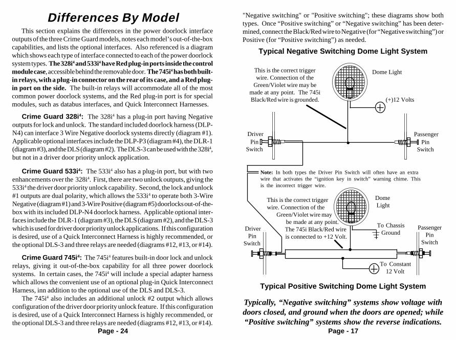
"Negative switching" or "Positive switching"; these diagrams show bothtypes. Once “Positive switching” or “Negative switching” has been deter-mined, connect the Black/Red wire to Negative (for “Negative switching”) orPositive (for “Positive switching”) as needed.
Typically, “Negative switching” systems show voltage withdoors closed, and ground when the doors are opened; while“Positive switching” systems show the reverse indications.
11121212
1212
Driver PinSwitch
12345678901231234567890123123456789012312345678901231234567890123123456789012312345678901231234567890123123456789012312345678901231234567890123123456789012312345678901231234567890123
To ChassisGround
Dome Light
To Constant 12 Volt
PassengerPin
Switch
Typical Positive Switching Dome Light System
111111
111111
111111
11111112
1212121212
PassengerPin
Switch
(+)12 Volts
DriverPin
Switch
Note: In both types the Driver Pin Switch will often have an extrawire that activates the “ignition key in switch” warning chime. Thisis the incorrect trigger wire.
123456789012123456789012123456789012123456789012123456789012123456789012123456789012123456789012123456789012123456789012123456789012123456789012123456789012123456789012
Dome Light
Typical Negative Switching Dome Light System
This is the correct triggerwire. Connection of the
Green/Violet wire may bemade at any point. The 745iBlack/Red wire is grounded.
This is the correct triggerwire. Connection of the
Green/Violet wire may be made at any point. The 745i Black/Red wire
is connected to +12 Volt.
Differences By Model
Page - 24
This section explains the differences in the power doorlock interfaceoutputs of the three Crime Guard models, notes each model’s out-of-the-boxcapabilities, and lists the optional interfaces. Also referenced is a diagramwhich shows each type of interface connected to each of the power doorlocksystem types. The 328i4 and 533i4 have Red plug-in ports inside the controlmodule case, accessible behind the removable door. The 745i4 has both built-in relays, with a plug-in connector on the rear of its case, and a Red plug-in port on the side. The built-in relays will accommodate all of the mostcommon power doorlock systems, and the Red plug-in port is for specialmodules, such as databus interfaces, and Quick Interconnect Harnesses.
Crime Guard 745i 4: The 745i4 features built-in door lock and unlockrelays, giving it out-of-the-box capability for all three power doorlocksystems. In certain cases, the 745i4 will include a special adapter harnesswhich allows the convenient use of an optional plug-in Quick InterconnectHarness, inn addition to the optional use of the DLS and DLS-3.
The 745i4 also includes an additional unlock #2 output which allowsconfiguration of the driver door priority unlock feature. If this configurationis desired, use of a Quick Interconnect Harness is highly recommended, orthe optional DLS-3 and three relays are needed (diagrams #12, #13, or #14).
Crime Guard 533i 4: The 533i4 also has a plug-in port, but with twoenhancements over the 328i4. First, there are two unlock outputs, giving the533i4 the driver door priority unlock capability. Second, the lock and unlock#1 outputs are dual polarity, which allows the 533i4 to operate both 3-WireNegative (diagram #1) and 3-Wire Positive (diagram #5) doorlocks out-of-the-box with its included DLP-N4 doorlock harness. Applicable optional inter-faces include the DLR-1 (diagram #3), the DLS (diagram #2), and the DLS-3which is used for driver door priority unlock applications. If this configurationis desired, use of a Quick Interconnect Harness is highly recommended, orthe optional DLS-3 and three relays are needed (diagrams #12, #13, or #14).
Crime Guard 328i 4: The 328i4 has a plug-in port having Negativeoutputs for lock and unlock. The standard included doorlock harness (DLP-N4) can interface 3 Wire Negative doorlock systems directly (diagram #1).Applicable optional interfaces include the DLP-P3 (diagram #4), the DLR-1(diagram #3), and the DLS (diagram #2). The DLS-3 can be used with the 328i4,but not in a driver door priority unlock application.

Page - 18
To Use Smart Trigger: After connection of the Green/Violetand Black/Red wire is completed, all that is needed is to install the SmartTrigger jumper in the correct polarity setting . To set the polarity, open theaccess door on the 745i4’s case. Next to the White 2-pin port for the backupbattery is the Smart Trigger standup; refer to the below diagrams.
If the Black/Red wire was connected to Negative polarity, the SmartTrigger jumper should be aligned to the left two pins (i.e.- inboard); if theBlack/Red wire was connected to Positive polarity, the Smart Trigger jumpershould be aligned right two pins (i.e.- outboard).
Setting “Positive Switching” Dome Light Smart Trigger
12345678901231234567890123123456789012312345678901231234567890123123456789012312345678901231234567890123123456789012312345678901231234567890123123456789012312345678901231234567890123
Green/Violet
10 AmpBlack/Red
Dome Light Wire
Dome Light
To Constant 12 Volt
Jumperconnects 2 right pins
Control Unit
2-Pin Backup Battery Connector
“Negative Switching” Dome Light Smart Trigger
Ground
123456789012123456789012123456789012123456789012123456789012123456789012123456789012123456789012123456789012123456789012123456789012123456789012123456789012
Green/Violet
10 AmpBlack/Red
Dome Light Wire
Dome Light
Jumperconnects 2 left pins
2-Pin Backup Battery Connector
Control Module
Page - 23
Other Doorlocking Systems: Beyond these three basic typesof power doorlocking systems, the scope of this Installation Manual willcover the interfacing of vacuum power doorlocking systems and how tointerface an added actuator. As the Crime Guard 533i4 and 745i4 are capableof “driver door priority unlock”, this option is also explained and diagramedin this booklet for the three basic power doorlock circuit types.
For properly detailed instructions on the various, specialty doorlockingsystems, please refer to Omega’s comprehensive Automotive Wiring Index,which consists of wiring information for each vehicle. Should the vehicle inquestion have a specialty power doorlocking system, a detailed wiringdiagram is included.
Lock
Unlock
Lock
Unlock
+
PassengerDoorlockActuator
DriverDoorlockActuator
PassengerDoorlock
Switch(“Secondary”)
DriverDoorlock
Switch(“Primary”)
+
Diagram Of A Typical 5 WireReversal Doorlocking System
“Lock” wire*
“Unlock” wire*
*The apparent reversal of the “Lock” and“Unlock” wires in this diagram is correct;note how when the switch contacts arepushed upward, as in unlocking, it is thelower wire which changes from Ground toPositive. Thus, it is the true “unlock” wire.
Interface performedwithin in this area

Page - 19
Not Using Smart Trigger: If the Smart Trigger feature is notdesired, connect the Green/Violet and Black/Red wires for the dome super-vision operation, but do not install the polarity selecting jumper. If this isdone, either the Green Negative door trigger wire or the Violet Positive DoorTrigger wire must be connected in order for the control unit to detect anopen door.
Power Doorlock InterfacesAlthough its primary purpose is the security of vehicle and contents, an
added benefit of a Crime Guard system is the convenience offered throughthe remote control operation of functions such as power doorlocks. All threeCrime Guard systems are capable, with the proper interface, of operating thevehicle's existing power doorlocks. Even if the vehicle is not equipped withpower doorlocks, it is still possible to add actuators to operate the manualmechanical doorlocks via remote control.
It is important to note that power doorlocking systems vary from vehicleto vehicle; therefore where one interface may be performed with partsincluded with the Crime Guard system, another installation may requireoptional parts. Basically, there are two approaches to performing the powerdoorlock interface: the use of a “plug-in” Quick Interconnect Harness; or“hardwiring” by direct wire-to-wire splicing between the security systeminterface and the vehicle’s wires. The Quick Interconnect Harness offers theeasiest, safest and most accurate method of interfacing a power doorlocksystem. Otherwise, if hardwiring, a basic understanding of the vehicle’spower doorlock system is most helpful.
Basic Types Of Power Doorlock Systems: The vastmajority of power doorlocks are found as only three different system types.All other power doorlock systems which may be encountered, such as thevacuum pump types found in older Mercedes vehicles and the single wiretypes which have appeared in some late model vehicles, are actually varia-tions or even combinations of the these three basic types:
3 Wire Negative
3 Wire Positive
5 Wire Reversal
Page - 22
5 Wire Reversal Systems: The 5 Wire Reversal system firstof all differs from the negative and positive pulse systems in the fact that thereare no relays or doorlock control unit.* As a side note, the 5 Wire Reversalsystem is also the type of circuit found after the relays in the other two typesof power doorlock systems. The five wires found at the doorlock switch are:
- One is Positive 12 Volts at all times.- Two show Ground at all times.- The remaining two are Grounded until the switch is operated, with
one wire changing from Ground to Positive 12 Volts upon “lock” andthe other changing from Ground to Positive 12 Volts upon “unlock”.
The 5 Wire Reversal system resembles the 3 Wire Positive system, as italso shows Positive 12 Volt pulses as it is operated, but the 5 Wire Reversalsystem’s wires rest at a full chassis Ground when not in operation. In this typeof system, the switches themselves supply the positive voltage directly tothe doorlock actuators, and, more importantly, provide the return groundpath. The important thing to remember is the wires in this system rest atground, which means that the wires must be "opened", or cut, to make theconnections. As in the example explained in the 3 Wire Positive section, aDMM would read around 0 ohms on the 5 Wire Reversal’s target wires.
The correct target wires are found between the vehicle’s power doorlockswitches. These two wires are both routed to the doorlock actuators and areconnected to either end of the actuator's motor winding. When either switchis pushed to one position, one of these two wires will have 12 volts. Thisvoltage flows through the wire to the actuator's motor winding, and since theother wire is still resting at ground an electrical circuit is completed. Whenthe switch is pushed to the opposite position the electrical flow is reversed.When the correct wires are found, they must be cut. Notice in the diagram(following page) that the driver's switch is the primary switch and referred toas the "switch" wires. The wires that go to the secondary switch are referredto as the "motor" wires. Even though the cut is made between the switches,the two sides are still correctly called the "switch" and the "motor" sides, withconsideration of "Primary" and "Secondary" switch.
* As always with the wide array of vehicle power doorlocking systems, it ispossible to encounter variations, especially in the case of an existingaftermarket doorlock system. A vehicle having a 5 Wire Reversal system doesnot absolutely rule out the absence of existing relays, most notably if thevehicle is pre-equipped with a remote entry or automatic locking system.

Page - 20
3-Wire Negative Systems: In 3 Wire Negative systems, thevehicle’s doorlock switch activates “lock” and “unlock” relays present in thevehicle, which can be found separate, within a bank of relays, or sometimeswithin a doorlock control unit. This power doorlock system is indicated bythe presence of three wires at the switch. Typically, of the three wires at theswitch:
- One wire is constant Ground.- One wire shows Ground when the switch is pushed to “lock”.- One wire shows Ground when the switch is pushed to “unlock”.
With the switch at “rest” (not being operated), these two wires will readvoltage, usually 12 volt positive but in some cases less. The wires from theswitches operate doorlock relays or a doorlock control unit with built-inrelays; the correct connection point isbetween the switches and the relays.
The best way to identify a doorlock system is to examine the doorlock switch'swiring . The names of the three systems are in fact derived from the numberof wires, and their polarity, as found at the doorlock switch, althoughvariations can be encountered*.
* These “variations” include illuminated switches, which will have more thanthe described number of wires, and “multiple switch assemblies” which havePower and/or Ground “bussed” internally, and therefore appear to have lessthan the described number of wires.
Diagram Of A Typical 3 WireNegative Doorlocking System
Vehicle's DoorlockRelay Control Unit
Doorlock Switch
Unlock
Lock
DoorlockActuators
+
+
Ground“Lock” wire
“Unlock” wire
Interface performedwithin in this area
Page - 21
3 Wire Positive Systems: A 3 Wire Positive is the same basicsystem as the 3 Wire Negative, except the vehicle's doorlock switches use 12volt positive pulses to operate the vehicle's doorlock relays or control unit.Examine the wires on the back of the switch. Of the three wires:- One wire is Constant Positive 12 Volts.- One wire will show Positive 12 Volts when the switch is pushed to "lock".- One wire will show Positive 12 Volts when the switch is pushed to
"unlock".With the switch at “rest” (not being operated), these two wires will read
Ground, but unlike the following 5 Wire Reversal system, this Ground is nota full, or “chassis” Ground. A Digital Multimeter (DMM) can be used to testthis. Set the meter for “ohms”, and put one meter lead on the target doorlockwire and the other to Chassis Ground. A 5 Wire Reversal system will read veryclose to “zero ohms”, which indicates that the target wire is resting at ChassisGround. If the target wire is indeed a 3 Wire Positive “switch” wire, the readingwill indicate Ground which is present through the vehicle’s relay coil, whichtypically produces a reading of approximately 150 ohms. As in a 3 WireNegative system, the wires from the switches operate doorlock relays or adoorlock control unit with built-in relays, and the correct connection pointis between the switches and the relays.
Doorlock Switch
Vehicle's DoorlockRelay Control Unit
UnlockLock
DoorlockActuators
+
+
Diagram Of A Typical 3 WirePositive Doorlocking System
“Unlock” wire
“Lock” wire
Interface performedwithin in this area