Embed Size (px)
Citation preview
Alcatel-Lucent 7950EXTENSIBLE ROUTING SYSTEM | RELEASE 13.0.R4INTERFACE CONFIGURATION GUIDE
INTERFACE CONFIGURATION GUIDE
Alcatel-Lucent – Proprietary & ConfidentialContains proprietary/trade secret information which is the property of Alcatel-Lucent. Not to be made available to, or copied or used by anyone who is not an employee of Alcatel-Lucent except when there is a valid non-disclosure agreement in place which covers such information and contains appropriate non-disclosure and limited use obligations.Copyright 2015 © Alcatel-Lucent. All rights reserved.

All specifications, procedures, and information in this document are subject to change and revision at any time without notice. The information contained herein is believed to be accurate as of the date of publication. Alcatel-Lucent provides no warranty, express or implied, regarding its contents. Users are fully responsible for application or use of the documentation.
Alcatel, Lucent, Alcatel-Lucent and the Alcatel-Lucent logo are trademarks of Alcatel-Lucent. All other trademarks are the property of their respective owners.
Copyright 2015 Alcatel-Lucent.
All rights reserved.
Disclaimers
Alcatel-Lucent products are intended for commercial uses. Without the appropriate network design engineering, they must not be sold, licensed or otherwise distributed for use in any hazardous environments requiring fail-safe performance, such as in the operation of nuclear facilities, aircraft navigation or communication systems, air traffic control, direct life-support machines, or weapons systems, in which the failure of products could lead directly to death, personal injury, or severe physical or environmental damage. The customer hereby agrees that the use, sale, license or other distribution of the products for any such application without the prior written consent of Alcatel-Lucent, shall be at the customer's sole risk. The customer hereby agrees to defend and hold Alcatel-Lucent harmless from any claims for loss, cost, damage, expense or liability that may arise out of or in connection with the use, sale, license or other distribution of the products in such applications.
This document may contain information regarding the use and installation of non-Alcatel-Lucent products. Please note that this information is provided as a courtesy to assist you. While Alcatel-Lucent tries to ensure that this information accurately reflects information provided by the supplier, please refer to the materials provided with any non-Alcatel-Lucent product and contact the supplier for confirmation. Alcatel-Lucent assumes no responsibility or liability for incorrect or incomplete information provided about non-Alcatel-Lucent products.
However, this does not constitute a representation or warranty. The warranties provided for Alcatel-Lucent products, if any, are set forth in contractual documentation entered into by Alcatel-Lucent and its customers.
This document was originally written in English. If there is any conflict or inconsistency between the English version and any other version of a document, the English version shall prevail.

7950 XRS Interface Configuration Guide Page 3
Table of Contents
Preface. . . . . . . . . . . . . . . . . . . . . . . . . . . . . . . . . . . . . . . . . . . . . . . . . . . . . . . . . . . . . . . . . . . . . . . . . . . . . . .9About This Guide . . . . . . . . . . . . . . . . . . . . . . . . . . . . . . . . . . . . . . . . . . . . . . . . . . . . . . . . . . . . . . . . . . . . .9
Audience . . . . . . . . . . . . . . . . . . . . . . . . . . . . . . . . . . . . . . . . . . . . . . . . . . . . . . . . . . . . . . . . . . . . . . . . .9List of Technical Publications . . . . . . . . . . . . . . . . . . . . . . . . . . . . . . . . . . . . . . . . . . . . . . . . . . . . . . . .10Searching for Information . . . . . . . . . . . . . . . . . . . . . . . . . . . . . . . . . . . . . . . . . . . . . . . . . . . . . . . . . . .11
To search for specific information in this guide. . . . . . . . . . . . . . . . . . . . . . . . . . . . . . . . . . . . . . . . .11To search for specific information in multiple documents . . . . . . . . . . . . . . . . . . . . . . . . . . . . . . . . .11
Technical Support . . . . . . . . . . . . . . . . . . . . . . . . . . . . . . . . . . . . . . . . . . . . . . . . . . . . . . . . . . . . . . . . .13
Getting StartedIn This Chapter . . . . . . . . . . . . . . . . . . . . . . . . . . . . . . . . . . . . . . . . . . . . . . . . . . . . . . . . . . . . . . . . . . . . . .15Alcatel-Lucent 7950 XRS-Series Router Configuration Process . . . . . . . . . . . . . . . . . . . . . . . . . . . . . . . .16
InterfacesIn This Chapter . . . . . . . . . . . . . . . . . . . . . . . . . . . . . . . . . . . . . . . . . . . . . . . . . . . . . . . . . . . . . . . . . . . . . .17Configuration Overview . . . . . . . . . . . . . . . . . . . . . . . . . . . . . . . . . . . . . . . . . . . . . . . . . . . . . . . . . . . . . . .18
Chassis Slots and Cards . . . . . . . . . . . . . . . . . . . . . . . . . . . . . . . . . . . . . . . . . . . . . . . . . . . . . . . . . . .18XMAx/C-XMAs. . . . . . . . . . . . . . . . . . . . . . . . . . . . . . . . . . . . . . . . . . . . . . . . . . . . . . . . . . . . . . . . . . . .19
Digital Diagnostics Monitoring . . . . . . . . . . . . . . . . . . . . . . . . . . . . . . . . . . . . . . . . . . . . . . . . . . . . . . . . . .20Alcatel-Lucent SFPs and XFPs . . . . . . . . . . . . . . . . . . . . . . . . . . . . . . . . . . . . . . . . . . . . . . . . . . . .24Statistics Collection . . . . . . . . . . . . . . . . . . . . . . . . . . . . . . . . . . . . . . . . . . . . . . . . . . . . . . . . . . . . .24
Ports . . . . . . . . . . . . . . . . . . . . . . . . . . . . . . . . . . . . . . . . . . . . . . . . . . . . . . . . . . . . . . . . . . . . . . . . . . . . . .25Port Types . . . . . . . . . . . . . . . . . . . . . . . . . . . . . . . . . . . . . . . . . . . . . . . . . . . . . . . . . . . . . . . . . . . . . . .25Port Features. . . . . . . . . . . . . . . . . . . . . . . . . . . . . . . . . . . . . . . . . . . . . . . . . . . . . . . . . . . . . . . . . . . . .27
Port State and Operational State . . . . . . . . . . . . . . . . . . . . . . . . . . . . . . . . . . . . . . . . . . . . . . . . . . .27802.1x Network Access Control . . . . . . . . . . . . . . . . . . . . . . . . . . . . . . . . . . . . . . . . . . . . . . . . . . . .29SONET/SDH Port Attributes. . . . . . . . . . . . . . . . . . . . . . . . . . . . . . . . . . . . . . . . . . . . . . . . . . . . . . .35SONET/ SDH Path Attributes. . . . . . . . . . . . . . . . . . . . . . . . . . . . . . . . . . . . . . . . . . . . . . . . . . . . . .35Ethernet Local Management Interface (E-LMI) . . . . . . . . . . . . . . . . . . . . . . . . . . . . . . . . . . . . . . . .36Link Layer Discovery Protocol (LLDP) . . . . . . . . . . . . . . . . . . . . . . . . . . . . . . . . . . . . . . . . . . . . . . .37
LAG. . . . . . . . . . . . . . . . . . . . . . . . . . . . . . . . . . . . . . . . . . . . . . . . . . . . . . . . . . . . . . . . . . . . . . . . . . . . . . .42LACP . . . . . . . . . . . . . . . . . . . . . . . . . . . . . . . . . . . . . . . . . . . . . . . . . . . . . . . . . . . . . . . . . . . . . . . . . . .42
LACP Multiplexing . . . . . . . . . . . . . . . . . . . . . . . . . . . . . . . . . . . . . . . . . . . . . . . . . . . . . . . . . . . . . .43Active-Standby LAG Operation . . . . . . . . . . . . . . . . . . . . . . . . . . . . . . . . . . . . . . . . . . . . . . . . . . . . . . .44LAG on Access QoS Consideration . . . . . . . . . . . . . . . . . . . . . . . . . . . . . . . . . . . . . . . . . . . . . . . . . . .46
Adapt QoS Modes . . . . . . . . . . . . . . . . . . . . . . . . . . . . . . . . . . . . . . . . . . . . . . . . . . . . . . . . . . . . . .46Per-fp-ing-queuing . . . . . . . . . . . . . . . . . . . . . . . . . . . . . . . . . . . . . . . . . . . . . . . . . . . . . . . . . . . . . .49Per-fp-egr-queuing . . . . . . . . . . . . . . . . . . . . . . . . . . . . . . . . . . . . . . . . . . . . . . . . . . . . . . . . . . . . . .50Per-fp-sap-instance . . . . . . . . . . . . . . . . . . . . . . . . . . . . . . . . . . . . . . . . . . . . . . . . . . . . . . . . . . . . .51
LAG and ECMP Hashing. . . . . . . . . . . . . . . . . . . . . . . . . . . . . . . . . . . . . . . . . . . . . . . . . . . . . . . . . . . .52Per Flow Hashing . . . . . . . . . . . . . . . . . . . . . . . . . . . . . . . . . . . . . . . . . . . . . . . . . . . . . . . . . . . . . . .53Per Link Hashing . . . . . . . . . . . . . . . . . . . . . . . . . . . . . . . . . . . . . . . . . . . . . . . . . . . . . . . . . . . . . . .59Explicit Per Link Hash Using LAG Link Mapping Profiles. . . . . . . . . . . . . . . . . . . . . . . . . . . . . . . . .62Consistent Per Service Hashing. . . . . . . . . . . . . . . . . . . . . . . . . . . . . . . . . . . . . . . . . . . . . . . . . . . .63ESM – LAG Hashing per Vport . . . . . . . . . . . . . . . . . . . . . . . . . . . . . . . . . . . . . . . . . . . . . . . . . . . .64

Page 4 7950 XRS Interface Configuration Guide
Table of Contents
LAG Hold Down Timers. . . . . . . . . . . . . . . . . . . . . . . . . . . . . . . . . . . . . . . . . . . . . . . . . . . . . . . . . . . . .68BFD over LAG Links . . . . . . . . . . . . . . . . . . . . . . . . . . . . . . . . . . . . . . . . . . . . . . . . . . . . . . . . . . . . . . .69Mixed Port-Speed LAG Support . . . . . . . . . . . . . . . . . . . . . . . . . . . . . . . . . . . . . . . . . . . . . . . . . . . . . .69
Point-to-Point (p2p) Redundant Connection Across Layer 2/3 VPN Network . . . . . . . . . . . . . . . . .71G.8032 Protected Ethernet Rings. . . . . . . . . . . . . . . . . . . . . . . . . . . . . . . . . . . . . . . . . . . . . . . . . . . . . . . .73Ethernet Port Monitoring. . . . . . . . . . . . . . . . . . . . . . . . . . . . . . . . . . . . . . . . . . . . . . . . . . . . . . . . . . . . . . .74802.3ah OAM . . . . . . . . . . . . . . . . . . . . . . . . . . . . . . . . . . . . . . . . . . . . . . . . . . . . . . . . . . . . . . . . . . . . . . .77
OAM Events . . . . . . . . . . . . . . . . . . . . . . . . . . . . . . . . . . . . . . . . . . . . . . . . . . . . . . . . . . . . . . . . . . .80Remote Loopback . . . . . . . . . . . . . . . . . . . . . . . . . . . . . . . . . . . . . . . . . . . . . . . . . . . . . . . . . . . . . .87802.3ah OAM PDU Tunneling for Epipe Service . . . . . . . . . . . . . . . . . . . . . . . . . . . . . . . . . . . . . . .87
MTU Configuration Guidelines . . . . . . . . . . . . . . . . . . . . . . . . . . . . . . . . . . . . . . . . . . . . . . . . . . . . . . . . . .88Deploying Preprovisioned Components . . . . . . . . . . . . . . . . . . . . . . . . . . . . . . . . . . . . . . . . . . . . . . . . . . .91Configuration Process Overview . . . . . . . . . . . . . . . . . . . . . . . . . . . . . . . . . . . . . . . . . . . . . . . . . . . . . . . .92Configuration Notes . . . . . . . . . . . . . . . . . . . . . . . . . . . . . . . . . . . . . . . . . . . . . . . . . . . . . . . . . . . . . . . . . .93Configuring Physical Ports with CLI . . . . . . . . . . . . . . . . . . . . . . . . . . . . . . . . . . . . . . . . . . . . . . . . . . . . . .95
Predefining Entities . . . . . . . . . . . . . . . . . . . . . . . . . . . . . . . . . . . . . . . . . . . . . . . . . . . . . . . . . . . . . . . .95Preprovisioning a Port . . . . . . . . . . . . . . . . . . . . . . . . . . . . . . . . . . . . . . . . . . . . . . . . . . . . . . . . . . . . . .97Maximizing Bandwidth Use . . . . . . . . . . . . . . . . . . . . . . . . . . . . . . . . . . . . . . . . . . . . . . . . . . . . . . . . . .98
Basic Configuration. . . . . . . . . . . . . . . . . . . . . . . . . . . . . . . . . . . . . . . . . . . . . . . . . . . . . . . . . . . . . . . . . . .99Common Configuration Tasks . . . . . . . . . . . . . . . . . . . . . . . . . . . . . . . . . . . . . . . . . . . . . . . . . . . . . . . . .100Configuring XCMs (Cards) and XMAs (MDAs). . . . . . . . . . . . . . . . . . . . . . . . . . . . . . . . . . . . . . . . . . . . .101
Configuring Forwarding Plane Parameters . . . . . . . . . . . . . . . . . . . . . . . . . . . . . . . . . . . . . . . . . . . . .102Configuring XMA Access and Network Pool Parameters . . . . . . . . . . . . . . . . . . . . . . . . . . . . . . . . . .103
Configuring Ports . . . . . . . . . . . . . . . . . . . . . . . . . . . . . . . . . . . . . . . . . . . . . . . . . . . . . . . . . . . . . . . . . . .104Configuring Port Pool Parameters. . . . . . . . . . . . . . . . . . . . . . . . . . . . . . . . . . . . . . . . . . . . . . . . . . . .104Changing Hybrid-Buffer-Allocation . . . . . . . . . . . . . . . . . . . . . . . . . . . . . . . . . . . . . . . . . . . . . . . . . . .107Configuring Ethernet Port Parameters . . . . . . . . . . . . . . . . . . . . . . . . . . . . . . . . . . . . . . . . . . . . . . . .108
Ethernet Network Port . . . . . . . . . . . . . . . . . . . . . . . . . . . . . . . . . . . . . . . . . . . . . . . . . . . . . . . . . .108Ethernet Access Port . . . . . . . . . . . . . . . . . . . . . . . . . . . . . . . . . . . . . . . . . . . . . . . . . . . . . . . . . . .109Configuring 802.1x Authentication Port Parameters . . . . . . . . . . . . . . . . . . . . . . . . . . . . . . . . . . .110
Configuring SONET/SDH Port Parameters . . . . . . . . . . . . . . . . . . . . . . . . . . . . . . . . . . . . . . . . . . . . .110Configuring LAG Parameters . . . . . . . . . . . . . . . . . . . . . . . . . . . . . . . . . . . . . . . . . . . . . . . . . . . . . . .111
Configuring BFD on LAG Links . . . . . . . . . . . . . . . . . . . . . . . . . . . . . . . . . . . . . . . . . . . . . . . . . . . 111Service Management Tasks . . . . . . . . . . . . . . . . . . . . . . . . . . . . . . . . . . . . . . . . . . . . . . . . . . . . . . . . . . .113
Modifying or Deleting an XMA (MDA) . . . . . . . . . . . . . . . . . . . . . . . . . . . . . . . . . . . . . . . . . . . . . . . . .113Modifying a Card Type . . . . . . . . . . . . . . . . . . . . . . . . . . . . . . . . . . . . . . . . . . . . . . . . . . . . . . . . . . . .114Deleting a Card . . . . . . . . . . . . . . . . . . . . . . . . . . . . . . . . . . . . . . . . . . . . . . . . . . . . . . . . . . . . . . . . . .115Deleting Port Parameters . . . . . . . . . . . . . . . . . . . . . . . . . . . . . . . . . . . . . . . . . . . . . . . . . . . . . . . . . .115
Card, MDAXMA, and Port Command Reference . . . . . . . . . . . . . . . . . . . . . . . . . . . . . . . . . . . . . . . . . . .117Command Hierarchies . . . . . . . . . . . . . . . . . . . . . . . . . . . . . . . . . . . . . . . . . . . . . . . . . . . . . . . . . . . .117
Configuration Commands. . . . . . . . . . . . . . . . . . . . . . . . . . . . . . . . . . . . . . . . . . . . . . . . . . . . . . . .159Forwarding Plane Commands . . . . . . . . . . . . . . . . . . . . . . . . . . . . . . . . . . . . . . . . . . . . . . . . . . . .292Show Commands . . . . . . . . . . . . . . . . . . . . . . . . . . . . . . . . . . . . . . . . . . . . . . . . . . . . . . . . . . . . . .325Clear Commands . . . . . . . . . . . . . . . . . . . . . . . . . . . . . . . . . . . . . . . . . . . . . . . . . . . . . . . . . . . . . .452Tools Commands . . . . . . . . . . . . . . . . . . . . . . . . . . . . . . . . . . . . . . . . . . . . . . . . . . . . . . . . . . . . . .455Debug Commands . . . . . . . . . . . . . . . . . . . . . . . . . . . . . . . . . . . . . . . . . . . . . . . . . . . . . . . . . . . . .460
Standards and Protocol Support ............................................................................................... 461

7950 XRS Interface Configuration Guide Page 5
List of Figures
InterfacesFigure 1: 802.1x Architecture. . . . . . . . . . . . . . . . . . . . . . . . . . . . . . . . . . . . . . . . . . . . . . . . . . . . . . . . . . . . . .30Figure 2: 802.1x Authentication Scenario . . . . . . . . . . . . . . . . . . . . . . . . . . . . . . . . . . . . . . . . . . . . . . . . . . . .31Figure 3: 802.1x EAPOL Timers (left) and RADIUS Timers (right) . . . . . . . . . . . . . . . . . . . . . . . . . . . . . . . . .33Figure 4: LLDP Internal Architecture for a Network Node . . . . . . . . . . . . . . . . . . . . . . . . . . . . . . . . . . . . . . . .38Figure 5: Generic Customer Use Case For LLDP . . . . . . . . . . . . . . . . . . . . . . . . . . . . . . . . . . . . . . . . . . . . . .39Figure 6: Active-Standby LAG Operation without Deployment Examples . . . . . . . . . . . . . . . . . . . . . . . . . . . .44Figure 7: LAG on Access Interconnection . . . . . . . . . . . . . . . . . . . . . . . . . . . . . . . . . . . . . . . . . . . . . . . . . . . .45Figure 8: LAG on Access Failure Switchover . . . . . . . . . . . . . . . . . . . . . . . . . . . . . . . . . . . . . . . . . . . . . . . . .45Figure 9: P2P Redundant Connection Through a Layer 2 VPN Network . . . . . . . . . . . . . . . . . . . . . . . . . . . .71Figure 10: MTU Configuration Example. . . . . . . . . . . . . . . . . . . . . . . . . . . . . . . . . . . . . . . . . . . . . . . . . . . . . .89Figure 11: Slot, XCM (card), XMA (mda), and Port Configuration and Implementation Flow . . . . . . . . . . . . .92

Page 6 7950 XRS Interface Configuration Guide
List of Figures

7950 XRS Interface Configuration Guide Page 7
List of Tables
Table 1: List of Technical Publications. . . . . . . . . . . . . . . . . . . . . . . . . . . . . . . . . . . . . . . . . . . . . . . . . . . . . . .10
Getting StartedTable 2: Configuration Process . . . . . . . . . . . . . . . . . . . . . . . . . . . . . . . . . . . . . . . . . . . . . . . . . . . . . . . . . . . .16
InterfacesTable 1: Real-Time DDM Information . . . . . . . . . . . . . . . . . . . . . . . . . . . . . . . . . . . . . . . . . . . . . . . . . . . . . . .22Table 2: DDM Alarms and Warnings . . . . . . . . . . . . . . . . . . . . . . . . . . . . . . . . . . . . . . . . . . . . . . . . . . . . . . . .23Table 3: Relationship of Port State and Oper State. . . . . . . . . . . . . . . . . . . . . . . . . . . . . . . . . . . . . . . . . . . . .28Table 4: Adapt QoS Bandwidth/Rate Distribution . . . . . . . . . . . . . . . . . . . . . . . . . . . . . . . . . . . . . . . . . . . . . .47Table 5: MTU Default Values . . . . . . . . . . . . . . . . . . . . . . . . . . . . . . . . . . . . . . . . . . . . . . . . . . . . . . . . . . . . .88Table 6: MTU Configuration Example Values . . . . . . . . . . . . . . . . . . . . . . . . . . . . . . . . . . . . . . . . . . . . . . . . .89

Page 8 7950 XRS Interface Configuration Guide
List of Tables
7950 XRS Interface Configuration Guide Page 9
Preface
About This Guide
This guide describes system concepts and provides configuration examples to provision XMA Control Modules (XCMs), also referred to as cards, XRS Media Adapters (XMAs), and ports.
This guide is organized into functional chapters and provides concepts and descriptions of the implementation flow, as well as Command Line Interface (CLI) syntax and command usage.
Audience
This guide is intended for network administrators who are responsible for configuring the 7950 XRS routers. It is assumed that the network administrators have an understanding of networking principles and configurations. Concepts described in this guide include the following:
• CLI concepts
• XCM, XMA, and port configuration
• QoS policies
• Services

List of Technical Publications
Page 10 7950 XRS Interface Configuration Guide
List of Technical Publications
The 7950 XRS documentation set is composed of the following guides:
Table 1: List of Technical Publications
Guide Description
7950 XRS Basic System Configuration Guide This guide describes basic system configurations and operations.
7950 XRS System Management Guide This guide describes system security and access configurations as well as event logging and accounting logs.
7950 XRS Interface Configuration Guide This guide describes XMA Control Module (XCM), XRS Media Adaptor (XMA), port and Link Aggregation Group (LAG) provisioning.
7950 XRS Router Configuration Guide This guide describes logical IP routing interfaces and associated attributes such as an IP address, as well as IP and MAC-based filtering, and VRRP and Cflowd.
7950 XRS Routing Protocols Guide This guide provides an overview of routing concepts and provides configuration examples for RIP, OSPF, IS-IS, BGP, and route policies.
7950 XRS MPLS Guide This guide describes how to configure Multiprotocol Label Switching (MPLS) and Label Distribution Protocol (LDP).
7950 XRS Services Guide This guide describes how to configure service parameters such as service distribution points (SDPs), customer information, and user services.
7950 XRS Layer 2 Services and EVPN Guide: VLL, VPLS, PBB, and EVPN
This guide describes Virtual Leased Lines (VLL), Virtual Private LAN Service (VPLS), Provider Backbone Bridging (PBB), and Ethernet VPN (EVPN).
7950 XRS Layer 3 Services Guide: Internet Enhanced Services and Virtual Private Routed Network Services
This guide describes Internet Enhanced Services (IES) and Virtual Private Routed Network (VPRN) services.
Searching for Information
7950 XRS Interface Configuration Guide Page 11
Searching for Information
You can use Adobe Reader, Release 6.0 or later, to search one or more PDF files for a term.
To search for specific information in this guide
1. From the Adobe Reader main menu, choose Edit > Search or Advanced Search. The Search panel opens.
2. Click on the In the current document radio button.
3. Enter the term to search for.
4. Select the following search criteria, if required:
• Whole words only• Case-Sensitive• Include Bookmarks• Include Comments
5. Click on the Search button. Adobe Reader displays the search results.
You can expand the entries by clicking on the + symbol.
To search for specific information in multiple documents
Note: The PDF files that you search must be in the same folder.
1. From the Adobe Reader main menu, choose Edit > Search or Advanced Search. The Search panel opens.
7950 XRS OAM and Diagnostics Guide This guide describes how to configure features such as service mirroring and Operations, Administration and Management (OAM) tools.
7950 XRS Quality of Service Guide This guide describes how to configure Quality of Service (QoS) policy management.
Table 1: List of Technical Publications
Guide Description

Searching for Information
Page 12 7950 XRS Interface Configuration Guide
2. Click on the All PDF Documents in radio button.
3. Choose the folder in which to search using the drop-down menu.
4. Enter the term to search for.
5. Select the following search criteria, if required:
• Whole words only• Case-Sensitive• Include Bookmarks• Include Comments
6. Click on the Search button. Adobe Reader displays the search results.
You can expand the entries for each file by clicking on the + symbol.

Technical Support
7950 XRS Interface Configuration Guide Page 13
Technical Support
If you purchased a service agreement for your 7950 SR-Series router and related products from a distributor or authorized reseller, contact the technical support staff for that distributor or reseller for assistance. If you purchased an Alcatel-Lucent service agreement, follow this link to contact an Alcatel-Lucent support representative and to access product manuals and documentation updates:
https://support2.alcatel-lucent.com/portal/olcsHome.do

Technical Support
Page 14 7950 XRS Interface Configuration Guide

7950 XRS Interface Configuration Guide Page 15
GETTING STARTED
In This Chapter
This chapter provides process flow information to configure XCMs (cards), XMAs (mdas) and ports.

Alcatel-Lucent 7950 XRS-Series Router Configuration Process
Page 16 7950 XRS Interface Configuration Guide
Alcatel-Lucent 7950 XRS-Series Router Configuration Pro-cess
Table 2 lists the tasks necessary to provision XMA Control Modules (XCMs) ,also referred to as cards, XRS Media Adaptors (XMAs), also referred to as MDAs, and ports.
This guide is presented in an overall logical configuration flow. Each section describes a software area and provides CLI syntax and command usage to configure parameters for a functional area.
Note: In SR OS any function that displays an IPv6 address or prefix changes to reflect rules described in RFC 5952, A Recommendation for IPv6 Address Text Representation. Specifically, hexadecimal letters in IPv6 addresses are now represented in lowercase, and the correct compression of all leading zeros is displayed. This changes visible display output compared to previous SR OS releases. Previous SR OS behavior can cause issues with operator scripts that use standard IPv6 address expressions and with libraries that have standard IPv6 parsing as per RFC 5952 rules. See the section on IPv6 Addresses in the Router Configuration Guide for more information.
NOTE: For consistency across platforms, XMAs are modelled in SR OS (CLI and SNMP) as MDAs (Media Dependant Adaptors).
Table 2: Configuration Process
Area Task Chapter
Provisioning Chassis slots and cards Chassis Slots and Cards on page 18
XMAs XMAx/C-XMAs on page 19
Ports Ports on page 25
Reference List of IEEE, IETF, and other proprietary entities.
Standards and Protocol Support on page 461

7950 XRS Interface Configuration Guide Page 17
Interfaces
In This Chapter
This chapter provides information about configuring chassis slots, cards, and ports.Topics in this chapter include:
• Configuration Overview on page 18
→ Chassis Slots and Cards on page 18→ XMAx/C-XMAs on page 19→ Digital Diagnostics Monitoring on page 20→ Ports on page 25
− Port Types on page 25
− Port Features on page 27
− Link Layer Discovery Protocol (LLDP) on page 37→ LAG on page 42
− LAG on Access QoS Consideration on page 46
− LAG and ECMP Hashing on page 52
− LAG Hold Down Timers on page 68
− BFD over LAG Links on page 69
− LACP on page 42
− Active-Standby LAG Operation on page 44
− LAG on Access QoS Consideration on page 46
• Ethernet Port Monitoring on page 74
• 802.3ah OAM on page 77
• MTU Configuration Guidelines on page 88
→ Deploying Preprovisioned Components on page 91
• Configuration Process Overview on page 92
• Configuration Notes on page 93

Configuration Overview
Page 18 7950 XRS Interface Configuration Guide
Configuration Overview
NOTE: This document uses the term preprovisioning in the context of preparing or preconfiguring entities such as chassis slots, cards, XCMs, XMAs, ports, and interfaces, prior to initialization. These entities can be installed but not enabled. When the entity is in a no shutdown state (administratively enabled), then the entity is considered to be provisioned.
Alcatel-Lucent routers provide the capability to configure chassis slots to accept specific XCM (card) and XMA (mda) types and set the relevant configurations before the equipment is actually installed. The preprovisioning ability allows you to plan your configurations as well as monitor and manage your router hardware inventory. Ports and interfaces can also be preprovisioned. When the functionality is needed, the card(s) can be inserted into the appropriate chassis slots when required.
The following sections are discussed.
• Chassis Slots and Cards on page 18
• XMAx/C-XMAs on page 19
• Ports on page 25
Chassis Slots and Cards
To pre-provision a chassis slot, the XCM (card) type must be specified. System administrators or network operators can enter card type information for each slot, allowing a range of card types in particular slots. From the range of card types, a card and accompanying XCMs are specified. When a card is installed in a slot and enabled, the system verifies that the installed card type matches the allowed card type. If the parameters do not match, the card remains off line. A preprovisioned slot can remain empty without conflicting with populated slots.
7950 XRS systems accept XCMs (cards) and XMAs (modeled as MDAs in CLI/SNMP). Refer to the appropriate system installation guide for more information.

Interface Configuration
7950 XRS Interface Configuration Guide Page 19
XMAx/C-XMAs
A chassis slot and card type must be specified and provisioned before an XMA/MDA can be preprovisioned. An XMA/MDA is provisioned when a type designated from the allowed XMA/MDA types is inserted. A preprovisioned XMA/MDA slot can remain empty without conflicting with populated slots.
Once installed and enabled, the system verifies that the installed XMA/MDA type matches the configured parameters. If the parameters do not match, the XMA/MDA remains offline.
A chassis slot, card type must be specified and provisioned before an XMA/MDA can be preprovisioned. An XMA/MDA is provisioned when a type designated from the allowed XMA/MDA type is inserted. A preprovisioned XMA/MDA slot can remain empty without conflicting with populated slots.
XMA output displays an “x” in the name of the card, and a C-XMA displays a "cx". The following displays a show card state command
A:Dut-A# show card state ===============================================================================Card State===============================================================================Slot/ Provisioned Type Admin Operational Num Num CommentsId Equipped Type (if different) State State Ports MDA -------------------------------------------------------------------------------1 xcm-x20 up up 2 1/1 cx20-10g-sfp up up 20 1/2 cx20-10g-sfp up up 20 2 xcm-x20 up up 2 2/1 cx20-10g-sfp up up 20 A cpm-x20 up up ActiveB cpm-x20 up up Standby===============================================================================
Once installed and enabled, the system verifies that the installed XMA/MDA type matches the configured parameters. If the parameters do not match, the XMA/MDA remains offline.
NOTE: For consistency across platforms, XMAs are modelled in SR OS (CLI and SNMP) as MDAs (Media Dependant Adaptors). The term XMA in this document refers to either a C-XMA or an XMA unless otherwise stated.

Digital Diagnostics Monitoring
Page 20 7950 XRS Interface Configuration Guide
Digital Diagnostics Monitoring
Some Alcatel-Lucent SFPs, XFPs, QSFPs, CFPs and the MSA DWDM transponder have Digital Diagnostics Monitoring (DDM) capability where the transceiver module maintains information about its working status in device registers including:
• Temperature
• Supply voltage
• Transmit (TX) bias current
• TX output power
• Received (RX) optical power
For the case of QSFP and CFPs, DDM Temperature and Supply voltage is available only at the Module level (to be shown in Table 2.
The section called Statistics Collection on page 24 shows the following QSFP and CFP sample DDM and DDM Lane information:
The QSFP and CFPs, the number of lanes is indicated by DDM attribute “Number of Lanes: 4”.
Subsequently, each lane threshold and measured values are shown per lane.
If a given lane entry is not supported by the given QSFP or CFP specific model, then it will be shown as “-“ in the entry.
A sample QSFP and CFP lane information is provided below:
Transceiver DataTransceiver Type : QSFP+Model Number : 3HE06485AAAA01 ALU IPUIBMY3AATX Laser Wavelength: 1310 nm Diag Capable : yesNumber of Lanes : 4Connector Code : LC Vendor OUI : e4:25:e9Manufacture date : 2012/02/02 Media : EthernetSerial Number : 12050188Part Number : DF40GELR411102AOptical Compliance : 40GBASE-LR4Link Length support: 10km for SMF===============================================================================Transceiver Digital Diagnostic Monitoring (DDM)=============================================================================== Value High Alarm High Warn Low Warn Low Alarm-------------------------------------------------------------------------------Temperature (C) +35.6 +75.0 +70.0 +0.0 -5.0Supply Voltage (V) 3.23 3.60 3.50 3.10 3.00==============================================================================================================================================================Transceiver Lane Digital Diagnostic Monitoring (DDM)=============================================================================== High Alarm High Warn Low Warn Low Alarm

Interface Configuration
7950 XRS Interface Configuration Guide Page 21
Lane Tx Bias Current (mA) 78.0 75.0 25.0 20.0Lane Rx Optical Pwr (avg dBm) 2.30 2.00 -11.02 -13.01-------------------------------------------------------------------------------Lane ID Temp(C)/Alm Tx Bias(mA)/Alm Tx Pwr(dBm)/Alm Rx Pwr(dBm)/Alm------------------------------------------------------------------------------- 1 - 43.5 - 0.42 2 - 46.7 - -0.38 3 - 37.3 - 0.55 4 - 42.0 - -0.52===============================================================================Transceiver Type : CFPModel Number : 3HE04821ABAA01 ALU IPUIBHJDAATX Laser Wavelength: 1294 nm Diag Capable : yesNumber of Lanes : 4Connector Code : LC Vendor OUI : 00:90:65Manufacture date : 2011/02/11 Media : EthernetSerial Number : C22CQYRPart Number : FTLC1181RDNL-A5Optical Compliance : 100GBASE-LR4Link Length support: 10km for SMF===============================================================================Transceiver Digital Diagnostic Monitoring (DDM)=============================================================================== Value High Alarm High Warn Low Warn Low Alarm-------------------------------------------------------------------------------Temperature (C) +48.2 +70.0 +68.0 +2.0 +0.0Supply Voltage (V) 3.24 3.46 3.43 3.17 3.13==============================================================================================================================================================Transceiver Lane Digital Diagnostic Monitoring (DDM)=============================================================================== High Alarm High Warn Low Warn Low Alarm-------------------------------------------------------------------------------Lane Temperature (C) +55.0 +53.0 +27.0 +25.0Lane Tx Bias Current (mA) 120.0 115.0 35.0 30.0Lane Tx Output Power (dBm) 4.50 4.00 -3.80 -4.30Lane Rx Optical Pwr (avg dBm) 4.50 4.00 -13.00 -16.00-------------------------------------------------------------------------------Lane ID Temp(C)/Alm Tx Bias(mA)/Alm Tx Pwr(dBm)/Alm Rx Pwr(dBm)/Alm------------------------------------------------------------------------------- 1 +47.6 59.2 0.30 -10.67 2 +43.1 64.2 0.27 -10.31 3 +47.7 56.2 0.38 -10.58 4 +51.1 60.1 0.46 -10.37===============================================================================
The transceiver is programmed with warning and alarm thresholds for low and high conditions that can generate system events. These thresholds are programmed by the transceiver manufacturer.
There are no CLI commands required for DDM operations, however, the show>port port-id detail command displays DDM information in the Transceiver Digital Diagnostics Monitoring output section.
DDM information is populated into the router’s MIBs, so the DDM data can be retrieved by Network Management using SNMP. Also, RMON threshold monitoring can be configured for the

Digital Diagnostics Monitoring
Page 22 7950 XRS Interface Configuration Guide
DDM MIB variables to set custom event thresholds if the factory-programmed thresholds are not at the desired levels.
The following are potential uses of the DDM data:
• Optics degradation monitoring — With the information returned by the DDM-capable optics module, degradation in optical performance can be monitored and trigger events based on custom or the factory-programmed warning and alarm thresholds.
• Link/router fault isolation — With the information returned by the DDM-capable optics module, any optical problem affecting a port can be quickly identified or eliminated as the potential problem source.
Supported real-time DDM features are summarized in Table 1.
Table 1: Real-Time DDM Information
Parameter User Units SFP/XFP Units
SFP XFP MSA DWDM
Temperature Celsius C Supported Supported Supported
Supply Voltage
Volts µV Supported Supported Not supported
TX Bias Current
mA µA Supported Supported Supported
TX Output Power
dBm (converted from mW)
mW Supported Supported Supported
RX Received Optical Power4
dBm (converted from dBm) (Avg Rx Power or OMA)
mW Supported Supported Supported
AUX1 parameter dependent (embedded in transceiver)
- Not supported Supported Not supported
AUX2 parameter dependent (embedded in transceiver)
- Not supported Supported Not supported

Interface Configuration
7950 XRS Interface Configuration Guide Page 23
The factory-programmed DDM alarms and warnings that are supported are summarized in Table 2.
Table 2: DDM Alarms and Warnings
Parameter SFP/XFP Units SFP XFP Required? MSA DWDM
Temperature - High Alarm- Low Alarm- High Warning - Low Warning
C Yes Yes Yes Yes
Supply Voltage- High Alarm- Low Alarm- High Warning- Low Warning
µV Yes Yes Yes No
TX Bias Current- High Alarm- Low Alarm- High Warning- Low Warning
µA Yes Yes Yes Yes
TX Output Power- High Alarm- Low Alarm- High Warning- Low Warning
mW Yes Yes Yes Yes
RX Optical Power- High Alarm- Low Alarm- High Warning- Low Warning
mW Yes Yes Yes Yes
AUX1- High Alarm- Low Alarm- High Warning- Low Warning
parameter dependent
(embedded in transceiver)
No Yes Yes No
AUX2- High Alarm- Low Alarm- High Warning- Low Warning
parameter dependent
(embedded in transceiver)
No Yes Yes No

Digital Diagnostics Monitoring
Page 24 7950 XRS Interface Configuration Guide
Alcatel-Lucent SFPs and XFPs
The availability of the DDM real-time information and warning/alarm status is based on the transceiver. It may or may not indicate that DDM is supported. Non-DDM and DDM-supported SFPs are distinguished by a specific ICS value.
For Alcatel-Lucent SFPs that do not indicate DDM support in the ICS value, DDM data is available although the accuracy of the information has not been validated or verified.
For non-Alcatel-Lucent transceivers, DDM information may be displayed, but Alcatel-Lucent is not responsible for formatting, accuracy, etc.
Statistics Collection
The DDM information and warnings/alarms are collected at one minute intervals, so the minimum resolution for any DDM events when correlating with other system events is one minute.
Note that in the Transceiver Digital Diagnostic Monitoring section of the show port port-id detail command output:
• If the present measured value is higher than the either or both High Alarm, High Warn thresholds; an exclamation mark “!” displays along with the threshold value.
• If the present measured value is lower than the either or both Low Alarm, Low Warn thresholds; an exclamation mark “!” displays along with the threshold value.
B:SR7-101# show port 2/1/6 detail......===============================================================================Transceiver Digital Diagnostic Monitoring (DDM), Internally Calibrated===============================================================================
Value High Alarm High Warn Low Warn Low Alarm-------------------------------------------------------------------------------Temperature (C) +33.0+98.0 +88.0 -43.0-45.0Supply Voltage (V) 3.31 4.12 3.60 3.00 2.80Tx Bias Current (mA)5.7 60.0 50.00.1 0.0Tx Output Power (dBm) -5.45 0.00 -2.00 -10.50 -12.50Rx Optical Power (avg dBm) -0.65-3.00! -4.00! -19.51 -20.51===============================================================================

Interface Configuration
7950 XRS Interface Configuration Guide Page 25
Ports
Port Types
Before a port can be configured, the slot must be provisioned with an XCM (card) type and XMA (mda) type.
The Alcatel-Lucent routers support the following port types:
• Ethernet — For example 10Gigabit Ethernet or 100G Ethernet
Router ports must be configured as either access, hybrid or network. The default is network.
→ Access ports — Configured for customer facing traffic on which services are configured. If a Service Access Port (SAP) is to be configured on the port or channel, it must be configured as an access port or channel. When a port is configured for access mode, the appropriate encapsulation type must be configured to distinguish the services on the port or channel. Once a port has been configured for access mode, one or more services can be configured on the port or channel depending on the encapsulation value.
→ Network ports — Configured for network facing traffic. These ports participate in the service provider transport or infrastructure network. Dot1q is supported on network ports.
→ Hybrid ports — Configured for access and network facing traffic. While the default mode of an Ethernet port remains network, the mode of a port cannot be changed between the access/network/hybrid values unless the port is shut down and the configured SAPs and/or interfaces are deleted. Hybrid ports allow a single port to operate in both access and network modes. MTU of port in hybrid mode is the same as in network mode. The default encap for hybrid port mode is dot1q; it also supports QinQ encapsulation on the port level. Null hybrid port mode is not supported.
Once the port is changed to hybrid, the default MTU of the port is changed to match the value of 9212 bytes currently used in network mode (higher than an access port); this is to ensure that both SAP and network VLANs can be accommodated. The configuration of all parameters in access and network contexts will continue to be done within the port using the same CLI hierarchy as in existing implementation. The difference is that a port configured in mode hybrid allows both ingress and egress contexts to be configured concurrently.
An Ethernet port configured in hybrid mode can have two values of encapsulation type: dot1q and QinQ. The NULL value is not supported since a single SAP is allowed, and can be achieved by configuring the port in the access mode, or a single network IP interface is allowed, which can be achieved by configuring the port in network mode. Hybrid mode can be enabled on a LAG port when the port is part of a

Port Types
Page 26 7950 XRS Interface Configuration Guide
single chassis LAG configuration. When the port is part of a multi-chassis LAG configuration, it can only be configured to access mode since MC-LAG is not supported on a network port and consequently is not supported on a hybrid port. The same restriction applies to a port that is part of an MC-Ring configuration.
For a hybrid port, the amount of the allocated port buffers in each of ingress and egress is split equally between network and access contexts using the following config>port>hybrid-buffer-allocation>ing-weight access access-weight [0..100] network network-weight [0..100] and config>port>hybrid-buffer-allocation>egr-weight access access-weight [0..100] network network-weight [0..100] commands.
Adapting the terminology in buffer-pools, the port’s access active bandwidth and network active bandwidth in each ingress and egress are derived as follows (egress formulas shown only):
− total-hybrid-port-egress-weights = access-weight + network-weight
− hybrid-port-access-egress-factor = access-weight / total-hybrid-port-egress-weights
− hybrid-port-network-egress-factor = network-weight / total-hybrid-port-egress-weights
− port-access-active-egress-bandwidth = port-active-egress-bandwidth x
− hybrid-port-access-egress-factor
− port-network-active-egress-bandwidth = port-active-egress-bandwidth x
− hybrid-port-network-egress-factor
When a named pool policy is applied to the hybrid port’s MDA or to the hybrid port, the port’s fair share of total buffers available to the MDA is split into three parts: default pools, named pools local to the port, and named pools on the ports MDA. This allocation can be altered by entering the corresponding values in the port-allocation-weights parameter.
• WAN PHY— 10G ethernet ports can be configured in WAN PHY mode (using the ethernet xgig config). When configuring the port to be in WAN mode, you can change certain SONET/SDH parameters to reflect the SONET/SDH requirements for this port.

Interface Configuration
7950 XRS Interface Configuration Guide Page 27
Port Features
• Port State and Operational State on page 27
• 802.1x Network Access Control on page 29
• SONET/SDH Port Attributes on page 35
→ SONET/ SDH Path Attributes on page 35
Port State and Operational State
There are two port attributes that are related and similar but have slightly different meanings: Port State and Operational State (or Operational Status).
The following descriptions are based on normal individual ports.
• Port State
→ Displayed in port summaries such as show port or show port 1/1→ tmnxPortState in the TIMETRA-PORT-MIB→ Values: None, Ghost, Down (linkDown), Link Up, Up
• Operational State
→ Displayed in the show output of a specific port such as show port 2/1/3→ tmnxPortOperStatus in the TIMETRA-PORT-MIB→ Values: Up (inService), Down (outOfService)
The behavior of Port State and Operational State are different for a port with link protocols configured (Eth OAM, Eth CFM or LACP for ethernet ports, LCP for PPP/POS ports). A port with link protocols configured will only transition to the Up Port State when the physical link is up and all the configured protocols are up. A port with no link protocols configured will transition from Down to Link Up and then to Up immediately once the physical link layer is up.
The SR OS linkDown and linkUp log events (events 2004 and 2005 in the SNMP application group) are associated with transitions of the port Operational State. Note that these events map to the RFC 2863, The Interfaces Group MIB, (which obsoletes RFC 2233, The Interfaces Group MIB using SMIv2) linkDown and linkUp traps as mentioned in the SNMPv2-MIB.
An Operational State of Up indicates that the port is ready to transmit service traffic (the port is physically up and any configured link protocols are up). The relationship between port Operational State and Port State in SR OS is shown in Table 3:

Port Features
Page 28 7950 XRS Interface Configuration Guide
Table 3: Relationship of Port State and Oper State
Operational State (Oper State or Oper Status) (as displayed in “show port x/y/z”)
Port State (as displayed in the show port summary)
For ports that have no link layer protocols configured
For ports that have link layer protocols configured
(PPP, LACP, 802.3ah EFM, 802.1ag Eth-CFM)
Up Up Up
Link Up (indicates the physical link is ready)
Up Down
Down Down Down

Interface Configuration
7950 XRS Interface Configuration Guide Page 29
802.1x Network Access Control
The Alcatel-Lucent 7950 XRS supports network access control of client devices (PCs, STBs, etc.) on an Ethernet network using the IEEE. 802.1x standard. 802.1x is known as Extensible Authentication Protocol (EAP) over a LAN network or EAPOL.
802.1x Modes
The Alcatel-Lucent 7950 XRS supports port-based network access control for Ethernet ports only. Every Ethernet port can be configured to operate in one of three different operation modes, controlled by the port-control parameter:
• force-auth — Disables 802.1x authentication and causes the port to transition to the authorized state without requiring any authentication exchange. The port transmits and receives normal traffic without requiring 802.1x-based host authentication. This is the default setting.
• force-unauth — Causes the port to remain in the unauthorized state, ignoring all attempts by the hosts to authenticate. The switch cannot provide authentication services to the host through the interface.
• auto — Enables 802.1x authentication. The port starts in the unauthorized state, allowing only EAPOL frames to be sent and received through the port. Both the router and the host can initiate an authentication procedure as described below. The port will remain in un-authorized state (no traffic except EAPOL frames is allowed) until the first client is authenticated successfully. After this, traffic is allowed on the port for all connected hosts.
Port Features
Page 30 7950 XRS Interface Configuration Guide
802.1x Basics
Figure 1: 802.1x Architecture
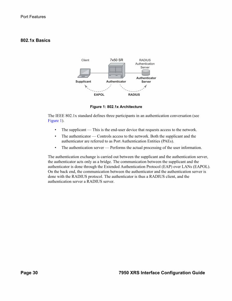
The IEEE 802.1x standard defines three participants in an authentication conversation (see Figure 1).
• The supplicant — This is the end-user device that requests access to the network.
• The authenticator — Controls access to the network. Both the supplicant and the authenticator are referred to as Port Authentication Entities (PAEs).
• The authentication server — Performs the actual processing of the user information.
The authentication exchange is carried out between the supplicant and the authentication server, the authenticator acts only as a bridge. The communication between the supplicant and the authenticator is done through the Extended Authentication Protocol (EAP) over LANs (EAPOL). On the back end, the communication between the authenticator and the authentication server is done with the RADIUS protocol. The authenticator is thus a RADIUS client, and the authentication server a RADIUS server.
OSSG038
Client Alcatel 7450 ESS RADIUS
Authentication
Server
Supplicant
EAPOL RADIUS
AuthenticatorAuthenticator
Server
7x50 SR
Interface Configuration
7950 XRS Interface Configuration Guide Page 31
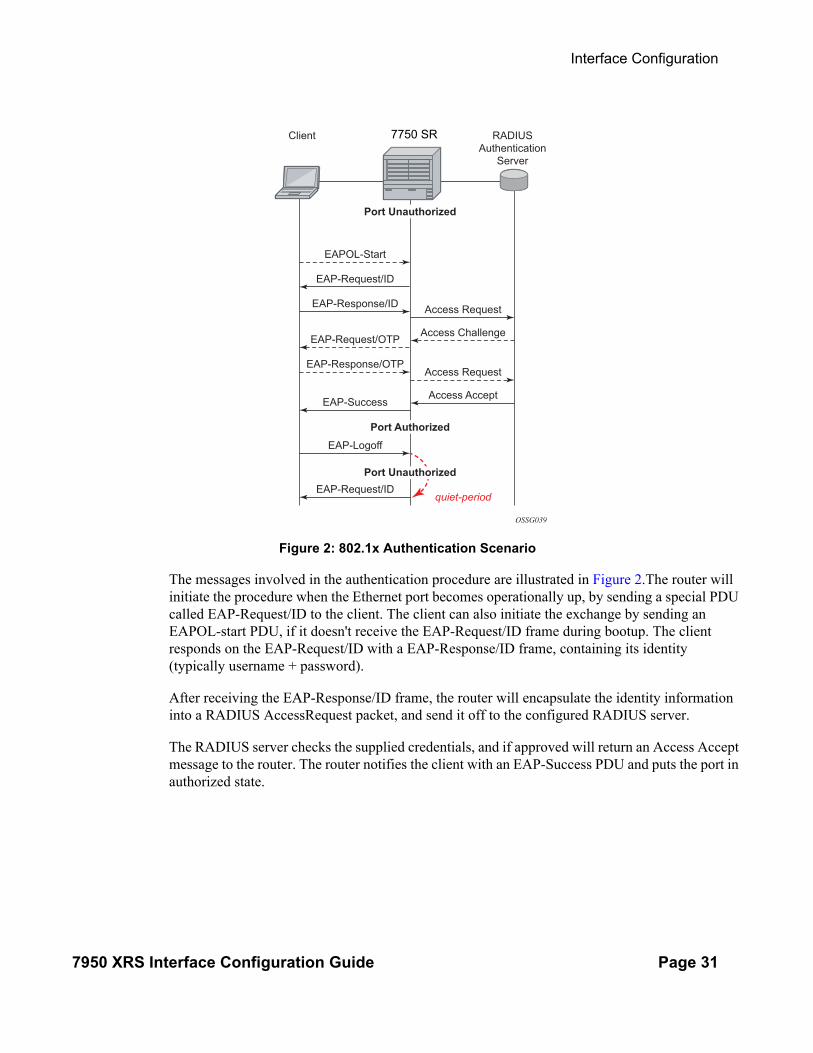
Figure 2: 802.1x Authentication Scenario
The messages involved in the authentication procedure are illustrated in Figure 2.The router will initiate the procedure when the Ethernet port becomes operationally up, by sending a special PDU called EAP-Request/ID to the client. The client can also initiate the exchange by sending an EAPOL-start PDU, if it doesn't receive the EAP-Request/ID frame during bootup. The client responds on the EAP-Request/ID with a EAP-Response/ID frame, containing its identity (typically username + password).
After receiving the EAP-Response/ID frame, the router will encapsulate the identity information into a RADIUS AccessRequest packet, and send it off to the configured RADIUS server.
The RADIUS server checks the supplied credentials, and if approved will return an Access Accept message to the router. The router notifies the client with an EAP-Success PDU and puts the port in authorized state.
OSSG039
Client
EAPOL-Start
Access Request
Access Challenge
Access Request
Access Accept
quiet-period
EAP-Request/ID
EAP-Response/ID
EAP-Request/OTP
EAP-Response/OTP
EAP-Success
EAP-Logoff
EAP-Request/ID
Alcatel 7450 ESS RADIUS
Authentication
Server
Port Unauthorized
Port Unauthorized
Port Authorized
7750 SR

Port Features
Page 32 7950 XRS Interface Configuration Guide
802.1x Timers
The 802.1x authentication procedure is controlled by a number of configurable timers and scalars. There are two separate sets, one for the EAPOL message exchange and one for the RADIUS message exchange. See Figure 3 for an example of the timers.
EAPOL timers:
• transit-period — Indicates how many seconds the Authenticator will listen for an EAP-Response/ID frame. If the timer expires, a new EAP-Request/ID frame will be sent and the timer restarted. The default value is 60. The range is 1-3600 seconds.
• supplicant-timeout — This timer is started at the beginning of a new authentication procedure (transmission of first EAP-Request/ID frame). If the timer expires before an EAP-Response/ID frame is received, the 802.1x authentication session is considered as having failed. The default value is 30. The range is 1 — 300.
• quiet-period — Indicates number of seconds between authentication sessions It is started after logoff, after sending an EAP-Failure message or after expiry of the supplicant-timeout timer. The default value is 60. The range is 1 — 3600.
RADIUS timer and scaler:
• max-auth-req — Indicates the maximum number of times that the router will send an authentication request to the RADIUS server before the procedure is considered as having failed. The default value is value 2. The range is 1 — 10.
• server-timeout — Indicates how many seconds the authenticator will wait for a RADIUS response message. If the timer expires, the access request message is sent again, up to max-auth-req times. The default value is 60. The range is 1 — 3600 seconds.

Interface Configuration
7950 XRS Interface Configuration Guide Page 33
Figure 3: 802.1x EAPOL Timers (left) and RADIUS Timers (right)
The router can also be configured to periodically trigger the authentication procedure automatically. This is controlled by the enable re-authentication and reauth-period parameters. Reauth-period indicates the period in seconds (since the last time that the authorization state was confirmed) before a new authentication procedure is started. The range of reauth-period is 1 — 9000 seconds (the default is 3600 seconds, one hour). Note that the port stays in an authorized state during the re-authentication procedure.
OSSG040-7750
Client
quiet-period
supplicant-timeout
transmit-period
EAP-Request/ID
EAP-Request/ID
EAP-Request/ID
EAP-Request/ID
Alcatel 7750 SR RADIUSAuthentication
Server
Client
Access Request
Access Request
Access Request
quiet-period
server-timeout
max-auth-request
EAP-Request/ID
EAP-Response/ID
EAP-Failure
EAP-Request/ID
Alcatel 7750 SR RADIUSAuthentication
Server
802.1x EAPOL Timers
802.1x RADIUS Timers
Port Unauthorized

Port Features
Page 34 7950 XRS Interface Configuration Guide
802.1x Tunneling
Tunneling of untagged 802.1x frames received on a port is supported for both Epipe and VPLS service using either null or default SAPs (for example 1/1/1:*) when the port dot1x port-control is set to force-auth.
When tunneling is enabled on a port (using the command configure port port-id ethernet dot1x tunneling), untagged 802.1x frames are treated like user frames and are switched into Epipe or VPLS services which have a corresponding null SAP or default SAP on that port. In the case of a default SAP, it is possible that other non-default SAPs are also present on the port. Untagged 802.1x frames received on other service types, or on network ports, are dropped. This is supported on FP2 or higher hardware.
When tunneling is required, it is expected that it is enabled on all ports into which 802.1x frames are to be received. The configuration of dot1x must be configured consistently across all ports in LAG as this is not enforced by the system.
Note that 802.1x frames are treated like user frames, that is, tunneled, by default when received on a spoke or mesh SDP.
802.1x Configuration and Limitations
Configuration of 802.1x network access control on the router consists of two parts:
• Generic parameters, which are configured under config>security>dot1x• Port-specific parameters, which are configured under config>port>ethernet>dot1x
801.x authentication:
• Provides access to the port for any device, even if only a single client has been authenticated.
• Can only be used to gain access to a pre-defined Service Access Point (SAP). It is not possible to dynamically select a service (such as a VPLS service) depending on the 802.1x authentication information.
• If 802.1x access control is enabled and a high rate of 802.1x frames are received on a port, that port will be blocked for a period of 5 minutes as a DOS protection mechanism.

Interface Configuration
7950 XRS Interface Configuration Guide Page 35
SONET/SDH Port Attributes
When an ethernet port is configured in WAN mode (xgig wan), you can change certain SONET/SDH parameters to reflect the SONET/SDH requirements for this port. See SONET/SDH Port Commands on page 245 for details.
SONET/ SDH Path Attributes
When an ethernet port is configured in WAN mode (xgig wan), you can change certain SONET/SDH parameters to reflect the SONET/SDH requirements for this port. See SONET/SDH Path Commands on page 249 for details.
Port Features
Page 36 7950 XRS Interface Configuration Guide
Ethernet Local Management Interface (E-LMI)
The Ethernet Local Management Interface (E-LMI) protocol is defined in Metro Ethernet Forum (MEF) technical specification MEF16. This specification largely based on Frame Relay - LMI defines the protocol and procedures that convey the information for auto-configuration of a CE device and provides the means for EVC status notification. MEF16 does not include link management functions like Frame Relay LMI does. In the Ethernet context that role is already accomplished with Clause 57 Ethernet OAM (formerly 802.3ah).
The SR OS currently implements the User Network Interface-Network (UNI-N) functions for status notification supported on Ethernet access ports with dot1q encapsulation type. Notification related to status change of the EVC and CE-VLAN ID to EVC mapping information is provided as a one to one between SAP and EVC.
The E-LMI frame encapsulation is based on IEEE 802.3 untagged MAC frame format using an ether-type of 0x88EE. The destination MAC address of the packet 01-80-C2-00-00-07 will be dropped by any 802.1d compliant bridge that does not support or have the E-LMI protocol enabled. This means the protocol cannot be tunneled.
Status information is sent from the UNI-N to the UNI-C, either because a status enquiry was received from the UNI-C or unsolicited. The Active and Not Active EVC status are supported. The Partially Active state is left for further study.
The bandwidth profile sub-information element associated with the EVC Status IE does not use information from the SAP QoS policy. A value of 0 is used in this release as MEF 16 indicates the bandwidth profile sub-IE is mandatory in the EVC Status IE. The EVC identifier is set to the description of the SAP and the UNI identifier is set to the description configured on the port. Further, the implementation associates each SAP with an EVC. Currently, support exists for CE-VLAN ID/EVC bundling mode.
As stated in the OAM Mapping section in the OAM and Diagnostics Guide, E-LMI the UNI-N can participates in the OAM fault propagation functions. This is a unidirectional update from the UNI-N to the UNI-C and interacting with service manager of VLL, VPLS, VPRN and IES services.

Interface Configuration
7950 XRS Interface Configuration Guide Page 37
Link Layer Discovery Protocol (LLDP)
The IEEE 802.1ab Link Layer Discovery Protocol (LLDP) standard defines protocol and management elements that are suitable for advertising information to stations attached to the same IEEE 802 LAN (emulation) for the purpose of populating physical or logical topology and device discovery management information databases. The protocol facilitates the identification of stations connected by IEEE 802 LANs/MANs, their points of interconnection, and access points for management protocols.
Note that LAN emulation and logical topology wording is applicable to customer bridge scenarios (enterprise/carrier of carrier) connected to a provider network offering a transparent LAN emulation service to their customers. It helps the customer bridges detect misconnection by an intermediate provider by offering a view of the customer topology where the provider service is represented as a LAN interconnecting these customer bridges.
The IEEE 802.1ab standard defines a protocol that:
• Advertises connectivity and management information about the local station to adjacent stations on the same IEEE 802 LAN.
• Receives network management information from adjacent stations on the same IEEE 802 LAN.
• Operates with all IEEE 802 access protocols and network media.
• Establishes a network management information schema and object definitions that are suitable for storing connection information about adjacent stations.
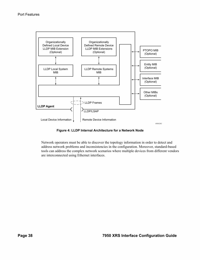
• Provides compatibility with a number of MIBs as depicted in Figure 4.
Port Features
Page 38 7950 XRS Interface Configuration Guide
Figure 4: LLDP Internal Architecture for a Network Node
Network operators must be able to discover the topology information in order to detect and address network problems and inconsistencies in the configuration. Moreover, standard-based tools can address the complex network scenarios where multiple devices from different vendors are interconnected using Ethernet interfaces.
OSSG262
OrganizationallyDefined Local DeviceLLDP MIB Extension
(Optional)
LLDP Local SystemMIB
OrganizationallyDefined Remote DeviceLLDP MIB Extensions
(Optional)
LLDP Remote SystemsMIB
PTOPO MIB(Optional)
Entity MIB(Optional)
LLDP/LSAP
Remote Device InformationLocal Device Information
LLDP Frames
Interface MIB(Optional)
Other MIBs(Optional)
LLDP Agent

Interface Configuration
7950 XRS Interface Configuration Guide Page 39
Figure 5: Generic Customer Use Case For LLDP
The example displayed in Figure 5 depicts a MPLS network that uses Ethernet interfaces in the core or as an access/handoff interfaces to connect to different kind of Ethernet enabled devices such as service gateway/routers, QinQ switches, DSLAMs or customer equipment.
IEEE 802.1ab LLDP running on each Ethernet interfaces in between all the above network elements may be used to discover the topology information.
Operators who are utilizing IOM3/IMM and above can tunnel the nearest-bridge at the port level using the tunnel-nearest-bridge command under the config>port>ethernet>lldp>destmac (nearest-bridge) hierarchy. The dest-mac nearest-bridge must be disabled for tunneling to occur.
OSSG263
Ethernet Links - FE/GE/10GE
MPLS/Native ETHCore
LAG
QinQSWs
DSLAMs
P
PE PE
PE PE
PE PE
PSG/R
SG/R

Port Features
Page 40 7950 XRS Interface Configuration Guide
LLDP Protocol Features
LLDP is an unidirectional protocol that uses the MAC layer to transmit specific information related to the capabilities and status of the local device. Separately from the transmit direction, the LLDP agent can also receive the same kind of information for a remote device which is stored in the related MIB(s).
LLDP itself does not contain a mechanism for soliciting specific information from other LLDP agents, nor does it provide a specific means of confirming the receipt of information. LLDP allows the transmitter and the receiver to be separately enabled, making it possible to configure an implementation so the local LLDP agent can either transmit only or receive only, or can transmit and receive LLDP information.
The information fields in each LLDP frame are contained in a LLDP Data Unit (LLDPDU) as a sequence of variable length information elements, that each include type, length, and value fields (known as TLVs), where:
• Type identifies what kind of information is being sent.
• Length indicates the length of the information string in octets.
• Value is the actual information that needs to be sent (for example, a binary bit map or an alphanumeric string that can contain one or more fields).
Each LLDPDU contains four mandatory TLVs and can contain optional TLVs as selected by network management:
• Chassis ID TLV
• Port ID TLV
• Time To Live TLV
• Zero or more optional TLVs, as allowed by the maximum size of the LLDPDU
• End Of LLDPDU TLV
The chassis ID and the port ID values are concatenated to form a logical identifier that is used by the recipient to identify the sending LLDP agent/port. Both the chassis ID and port ID values can be defined in a number of convenient forms. Once selected however, the chassis ID/port ID value combination remains the same as long as the particular port remains operable.
A non-zero value in the TTL field of the Time To Live TLV tells the receiving LLDP agent how long all information pertaining to this LLDPDU’s identifier will be valid so that all the associated information can later be automatically discarded by the receiving LLDP agent if the sender fails to update it in a timely manner. A zero value indicates that any information pertaining to this LLDPDU’s identifier is to be discarded immediately.
Note that a TTL value of zero can be used, for example, to signal that the sending port has initiated a port shutdown procedure. The End Of LLDPDU TLV marks the end of the LLDPDU.

Interface Configuration
7950 XRS Interface Configuration Guide Page 41
The implementation defaults to setting the port-id field in the LLDP OAMPDU to tx-local. This encodes the port-id field as ifIndex (sub-type 7) of the associated port. This is required to support some releases of SAM. SAM may use the ifIndex value to properly build the Layer Two Topology Network Map. However, this numerical value is difficult to interpret or readily identify the LLDP peer when reading the CLI or MIB value without SAM. Including the port-desc option as part of the tx-tlv configuration allows an ALU remote peer supporting port-desc preferred display logic (11.0r1) to display the value in the port description TLV instead of the port-id field value. This does not change the encoding of the port-id field. That value continues to represent the ifIndex. In some environments, it may be important to select the specific port information that is carried in the port-id field. The operator has the ability to control the encoding of the port-id information and the associated subtype using the port-id-subtype option. Three options are supported for the port-id-subtype:
tx-if-alias — Transmit the ifAlias String (subtype 1) that describes the port as stored in the IF-MIB, either user configured description or the default entry (ie 10/100/Gig ethernet SFP)
tx-if-name — Transmits the ifName string (subtype 5) that describes the port as stored in the IF-MIB, ifName info.
tx-local — The interface ifIndex value (subtype 7)
IPv6 (address subtype 2) and IPv4 (address subtype 1) LLDP System Management addresses are supported.

LAG
Page 42 7950 XRS Interface Configuration Guide
LAG
Based on the IEEE 802.1ax standard (formerly 802.3ad), Link Aggregation Groups (LAGs) can be configured to increase the bandwidth available between two network devices, depending on the number of links installed. LAG also provides redundancy in the event that one or more links participating in the LAG fail. All physical links in a given LAG links combine to form one logical interface.
Packet sequencing must be maintained for any given session. The hashing algorithm deployed by Alcatel-Lucent routers is based on the type of traffic transported to ensure that all traffic in a flow remains in sequence while providing effective load sharing across the links in the LAG.
LAGs must be statically configured or formed dynamically with Link Aggregation Control Protocol (LACP). The optional marker protocol described in IEEE 802.1ax is not implemented. LAGs can be configured on network and access ports.
The LAG load sharing is executed in hardware, which provides line rate forwarding for all port types.
SR OS LAG implementation supports LAG that with all member ports of the same speed and LAG with mixed port-speed members (see later section for details).
SR OS LAG implementation is supported on access and network interfaces.
LACP
Under normal operation, all non-failing links in a given LAG will become active and traffic is load balanced across all active links. In some circumstances, however, this is not desirable. Instead, it desired that only some of the links are active (for example, all links on the same IOM) and the other links be kept in stand-by condition.
LACP enhancements allow active lag-member selection based on particular constrains. The mechanism is based on the IEEE 802.1ax standard so interoperability is ensured.
To use LACP on a given LAG, operator must enable LACP on the LAG including, if desired, selecting non-default LACP mode: active/passive and configuring administrative key to be used (configure lag lacp). IN addition an operator can configure desired LACP transmit interval (configure lag lacp-xmit-interval).
When LACP is enabled, an operator can see LACP changes through traps/log messages logged against the LAG. See TIMETRA-LAG-MIB.mib for more details.

Interface Configuration
7950 XRS Interface Configuration Guide Page 43
LACP Multiplexing
The 7950 XRS supports two modes of multiplexing RX/TX control for LACP: coupled and independent.
In coupled mode (default), both RX and TX are enabled or disabled at the same time whenever a port is added or removed from a LAG group.
In independent mode, RX is first enabled when a link state is UP. LACP sends an indication to the far-end that it is ready to receive traffic. Upon the reception of this indication, the far-end system can enable TX. Therefore, in independent RX/TX control, LACP adds a link into a LAG only when it detects that the other end is ready to receive traffic. This minimizes traffic loss that might occur in coupled mode if a port is added into a LAG before notifying the far-end system or before the far-end system is ready to receive traffic. Similarly, on link removals from LAG, LACP turns off the distributing and collecting bit and informs the far-end about the state change. This allows the far-end side to stop sending traffic as soon as possible.
Independent control provides for lossless operation for unicast traffic in most scenarios when adding new members to a LAG or when removing members from a LAG. It also reduces loss for multicast and broadcast traffic. When adding a port to LAG in a high scaled deployment, and that port is the first to be added to the LAG on that forwarding complex, it is recommended to first shut down the port, add the port to the LAG, and then re-enable the port after a short delay to allow for forwarding to be reprogrammed. This procedure minimizes outages.
Note that independent and coupled mode are interoperable (i.e. connected systems can have either mode set).

Active-Standby LAG Operation
Page 44 7950 XRS Interface Configuration Guide
Active-Standby LAG Operation
Active/standby LAG is used to provide redundancy by logically dividing LAG into subgroups. The LAG is divided into subgroups by either assigning each LAG’s ports to an explicit subgroup (1 by default), or by automatically grouping all LAG’s ports residing on the same line card into a unique sub-group (auto-iom) or by automatically grouping all LAG’s ports residing on the same MDA into a unique sub-group (auto-mda). When a LAG is divided into sub-groups, only a single sub-group is elected as active. Which sub-group is selected depends on selection criterion chosen.
The active/standby decision for LAG member links is a local decision driven by pre-configured selection-criteria. When LACP is configured, this decision was communicated to remote system using LACP signalling.
To allow non-LACP operation, an operator must disable LACP on a given LAG and select transmitter-driven standby signaling (configure lag standby-signaling power-off). As a consequence, the transmit laser will be switched off for all LAG members in standby mode. On switch over (active-links failed) the laser will be switched on all standby LAG members so they can become active.
When the power-off is selected as the standby-signaling, the selection-criteria best-port can be used.
It will not be possible to have an active LACP in power-off mode before the correct selection criteria is selected.
Figure 6: Active-Standby LAG Operation without Deployment Examples
Figure 6 depicts how LAG in Active/Standby mode can be deployed towards a DSLAM access using sub-groups with auto-iom sub-group selection. LAG links are divided into two sub-groups (one per line card).
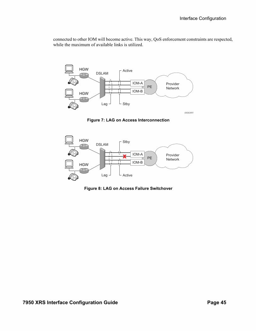
In case of a link failure, Figure 7 and Figure 8, the switch over behavior ensures that all lag-members connected to the same IOM as failing link will become stand-by and lag-members
LAG
MC-LAGMC-LAGMC-LAG
Interface Configuration
7950 XRS Interface Configuration Guide Page 45
connected to other IOM will become active. This way, QoS enforcement constraints are respected, while the maximum of available links is utilized.
Figure 7: LAG on Access Interconnection
Figure 8: LAG on Access Failure Switchover
DSLAM
Lag Stby
Active
OSSG095
HGW
HGW
ProviderNetworkPE
IOM-A
IOM-B
DSLAM
Lag
Stby
Active
HGW
HGW
ProviderNetworkPE
IOM-A
IOM-B

LAG on Access QoS Consideration
Page 46 7950 XRS Interface Configuration Guide
LAG on Access QoS Consideration
The following section describes various QoS related features applicable to LAG on access.
Adapt QoS Modes
Link Aggregation is supported on access side with access/hybrid ports. Similarly to LAG on network side, LAG on access is used to aggregate Ethernet ports into all active or active/standby LAG. The difference with LAG on networks lies in how the QoS/H-QoS is handled. Based on hashing configured, a given SAP’s traffic can be sprayed on egress over multiple LAG ports or can always use a single port of a LAG. There are three user-selectable modes that allow operator to best adapt QoS configured to a LAG the SAPs are using:
1. adapt-qos distributed (default)
In a distributed mode the SLA is divided among all line cards proportionally to the number of ports that exist on that line card for a given LAG. For example a 100Mbps PIR with 2 LAG links on IOM A and 3 LAG links on IOM B would result in IOM A getting 40 Mbps PIR and IOM B getting 60Mbps PIR. Thanks to such distribution, SLA can be enforced. The disadvantage is that a single flow is limited to IOM’s share of the SLA. This mode of operation may also result in underrun due to a “hash error” (traffic not sprayed equally over each link). This mode is best suited for services that spray traffic over all links of a LAG.
2. adapt-qos link
In a link mode the SLA is given to each and every port of a LAG. With the example above, each port would get 100 Mbps PIR. The advantage of this method is that a single flow can now achieve the full SLA. The disadvantage is that the overall SLA can be exceeded, if the flows span multiple ports. This mode is best suited for services that are guaranteed to hash to a single egress port.
3. adapt-qos port-fair
Port-fair distributes the SLA across multiple line cards relative to the number of active LAG ports per card (in a similar way to distribute mode) with all LAG QoS objects parented to scheduler instances at the physical port level (in a similar way to link mode). This provides a fair distribution of bandwidth between cards and ports whilst ensuring that the port bandwidth is not exceeded. Optimal LAG utilization relies on an even hash spraying of traffic to maximize the use of the schedulers' and ports' bandwidth. With the example above, enabling port-fair would result in all five ports getting 20Mbps.
When port-fair mode is enabled, per-Vport hashing is automatically disabled for subscriber traffic such that traffic sent to the Vport no longer uses the Vport as part of the hashing algorithm. Any QoS object for subscribers, and any QoS object for SAPs with explicitly configured hashing to a single egress LAG port, will be given the full bandwidth

Interface Configuration
7950 XRS Interface Configuration Guide Page 47
configured for each object (in a similar way to link mode). A Vport used together with an egress port scheduler is supported with a LAG in port-fair mode, whereas it is not supported with a distribute mode LAG.
4. adapt-qos distributed include-egr-hash-cfg
This mode can be considered a mix of link and distributed mode. The mode uses the configured hashing for LAG/SAP/service to choose either link or distributed adapt-qos modes. The mode allows:
→ SLA enforcement for SAPs that through configuration are guaranteed to hash to a single egress link using full QoS per port (as per link mode)
→ SLA enforcement for SAPs that hash to all LAG links proportional distribution of QoS SLA amongst the line cards (as per distributed mode)
→ SLA enforcement for multi service sites (MSS) that contain any SAPs regardless of their hash configuration using proportional distribution of QoS SLA amongst the line cards (as per distributed mode)
The following caveats apply to adapt-qos distributed include-egr-hash-cfg,
• The feature requires chassis mode D.
• LAG mode must be access or hybrid.
• The operator cannot change from adapt-qos distribute include-egr-hash-cfg to adapt-qos distribute when link-map-profiles or per-link-hash is configured.
• The operator cannot change from adapt-qos link to adapt-qos distribute include-egr-hash-cfg on a LAG with any configuration.
• Platforms supported except 7710 c12/c4, 7450 ESS-1
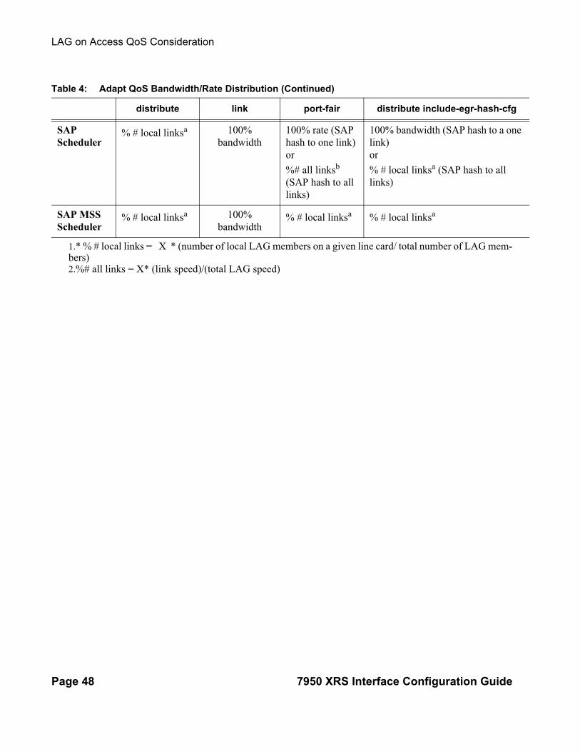
Table 4 shows examples of rate/BW distributions based on the adapt-qos mode used:
Table 4: Adapt QoS Bandwidth/Rate Distribution
distribute link port-fair distribute include-egr-hash-cfg
SAP Queues
% # local links1 100% rate 100% rate (SAP hash to one link)or
%# all links2 (SAP hash to all links)
100% rate (SAP hash to one link) or
% # local linksa (SAP hash to all links)
LAG on Access QoS Consideration
Page 48 7950 XRS Interface Configuration Guide
SAP Scheduler
% # local linksa 100% bandwidth
100% rate (SAP hash to one link)or
%# all linksb (SAP hash to all links)
100% bandwidth (SAP hash to a one link) or
% # local linksa (SAP hash to all links)
SAP MSS Scheduler
% # local linksa 100% bandwidth
% # local linksa % # local linksa
1.* % # local links = X * (number of local LAG members on a given line card/ total number of LAG mem-bers)2.%# all links = X* (link speed)/(total LAG speed)
Table 4: Adapt QoS Bandwidth/Rate Distribution (Continued)
distribute link port-fair distribute include-egr-hash-cfg

Interface Configuration
7950 XRS Interface Configuration Guide Page 49
Per-fp-ing-queuing
Per-fp-ing-queuing optimization for LAG ports provides the ability to reduce the number of hardware queues assigned on each LAG SAP on ingress when the flag at LAG level is set for per-fp-ing-queuing.
When the feature is enabled in the config>lag>access context, the queue allocation for SAPs on a LAG will be optimized and only one queuing set per ingress forwarding path (FP) is allocated instead of one per port.
The following rules will apply for configuring the per-fp-ing-queuing at LAG level:
• To enable per-fp-ing-queuing, the LAG must be in access mode
• The LAG mode cannot be set to network mode when the feature is enabled
• Per-fp-ing-queuing can only be set if no port members exists in the LAG

LAG on Access QoS Consideration
Page 50 7950 XRS Interface Configuration Guide
Per-fp-egr-queuing
Per-fp-egr-queuing optimization for LAG ports provides the ability to reduce the number of egress resources consumed by each SAP on a LAG, and by any encap groups that exist on those SAPs.
When the feature is enabled in the config>lag>access context, the queue and virtual scheduler allocation will be optimized. Only one queuing set and one H-QoS virtual scheduler tree per SAP/encap group will be allocated per egress forwarding path (FP) instead of one set per each port of the LAG. In case of a link failure/recovery, egress traffic uses failover queues while the queues are moved over to a newly active link.
Per-fp-egr-queuing can be enabled on existing LAG with services as long as the following conditions are met.
• The LAG’s mode must be access or hybrid.
• The LAG’s port-type must be standard.
• The LAG must have either per-link-hash enabled or all SAPs on the LAG must use per-service-hashing only and be of a type: VPLS SAP, i-VPLS SAP, or e-Pipe VLL or PBB SAP.
• The system must be, at minimum, in chassis mode d (configure>system>chassis-mode)
To disable per-fp-egr-queuing, all ports must first be removed from a given LAG.

Interface Configuration
7950 XRS Interface Configuration Guide Page 51
Per-fp-sap-instance
Per-fp-sap-instance optimization for LAG ports provides the ability to reduce the number of SAP instance resources consumed by each SAP on a lag.
When the feature is enabled, in the config>lag>access context, a single SAP instance is allocated on ingress and on egress per each forwarding path instead of one per port. Thanks to an optimized resource allocation, the SAP scale on a line card will increase, if a LAG has more than one port on that line card. Because SAP instances are only allocated per forwarding path complex, h/w reprogramming must take place when as result of LAG links going down or up, a SAP is moved from one LAG port on a given line card to another port on a given line card within the same forwarding complex. This results in an increased data outage when compared to per-fp-sap-instance feature being disabled. During the reprogramming, failover queues are used when SAP queues are reprogrammed to a new port. Any traffic using failover queues will not be accounted for in SAPs statistics and will be processed at best-effort priority.
The following rules apply when configuring per-fp-sap-instance on a given LAG:
• Minimum chassis mode D is required.
• Per-fp-sap-ingress-queuing and per-fp-sap-egr-queuing must be enabled.
• The functionality can be enabled/disabled on LAG with no member ports only. Services can be configured.
Other caveats:
• SAP instance optimization applies to LAG-level. Whether a LAG is sub-divided into sub-groups or not, the resources are allocated per forwarding path for all complexes LAG’s links are configured on (i.e. irrespective of whether a given sub-group a SAP is configured on uses that complex or not).
• Egress statistics continue to be returned per port when SAP instance optimization is enabled. If a LAG links are on a single forwarding complex, all ports but one will have no change in statistics for the last interval – unless a SAP moved between ports during the interval.
• Rollback that changes per-fp-sap-instance configuration is service impacting.

LAG and ECMP Hashing
Page 52 7950 XRS Interface Configuration Guide
LAG and ECMP Hashing
When a requirement exists to increase the available bandwidth for a logical link that exceeds the physical bandwidth or add redundancy for a physical link, typically one of two methods is applied: equal cost multi-path (ECMP) or Link Aggregation (LAG). A systemcan deploy both at the same time using ECMP of two or more Link Aggregation Groups (LAG) and/or single links.
Different types of hashing algorithms can be employed to achieve one of the following objectives:
• ECMP and LAG load balancing should be influenced solely by the offered flow packet. This is referred to as per-flow hashing.
• ECMP and LAG load balancing should maintain consistent forwarding within a given service. This is achieved using consistent per-service hashing.
• LAG load balancing should maintain consistent forwarding on egress over a single LAG port for a specific network interface, SAP, etc. This is referred as per link hashing (including explicit per link hashing with LAG link map profiles). Note that if multiple ECMP paths use a LAG with per link hashing, the ECMP load balancing is done using either per flow or consistent per service hashing.
These hashing methods are described in the following subsections. Although multiple hashing options may be configured for a given flow at the same time, only one method will be selected to hash the traffic based on the following decreasing priority order:
For ECMP load balancing:
1. Consistent per service hashing2. Per flow hashing
For LAG load balancing:
1. LAG link map profile2. Per link hash3. Consistent per service hashing4. Per flow hashing

Interface Configuration
7950 XRS Interface Configuration Guide Page 53
Per Flow Hashing
Per flow hashing uses information in a packet as an input to the hash function ensuring that any given flow maps to the same egress LAG port/ECMP path. Note that because the hash uses information in the packet, traffic for the same SAP/interface may be sprayed across different ports of a LAG or different ECMP paths. If this is not desired, other hashing methods outlined in this section can be used to change that behavior. Depending on the type of traffic that needs to be distributed into an ECMP and/or LAG, different variables are used as input to the hashing algorithm that determines the next hop selection. The following outlines default per flow hashing behavior for those different types of traffic:
• VPLS known unicast traffic is hashed based on the IP source and destination addresses for IP traffic, or the MAC source and destination addresses for non-IP traffic. The MAC SA/DA are hashed and then, if the Ethertype is IPv4 or IPv6, the hash is replaced with one based on the IP source address/destination address.
• VPLS multicast, broadcast and unknown unicast traffic.
→ Traffic transmitted on SAPs is not sprayed on a per-frame basis, but instead the service ID is used to pick ECMP and LAG paths statically.
→ Traffic transmitted on SDPs is hashed on a per packet basis in the same way as VPLS unicast traffic. However, per packet hashing is applicable only to the distribution of traffic over LAG ports, as the ECMP path is still chosen statically based on the service ID.
Data is hashed twice to get the ECMP path. If LAG and ECMP are performed on the same frame, the data will be hashed again to get the LAG port (three hashes for LAG). However, if only LAG is performed, then hashing will only be performed twice to get the LAG port.
→ Multicast traffic transmitted on SAPs with IGMP snooping enabled is load-balanced based on the internal multicast ID, which is unique for every (s,g) record. This way, multicast traffic pertaining to different streams is distributed across different LAG member ports.
→ The hashing procedure that used to be applied for all VPLS BUM traffic would result in PBB BUM traffic being sent out on BVPLS SAP to follow only a single link when MMRP was not used. Therefore, in chassis mode D, traffic flooded out on egress BVPLS SAPs is now load spread using the algorithm described above for VPLS known unicast.
• Unicast IP traffic routed by a router is hashed using the IP SA/DA in the packet.
• MPLS packet hashing at an LSR is based on the whole label stack, along with the incoming port and system IP address. Note that the EXP/TTL information in each label is not included in the hash algorithm. This method is referred to as Label-Only Hash option and is enabled by default, or can be re-instated in CLI by entering the lbl-only keyword. A couple of options to further hash on the header of an IP packet in the payload of the MPLS packet are also provided.

LAG and ECMP Hashing
Page 54 7950 XRS Interface Configuration Guide
• VLL traffic from a service access point is not sprayed on a per-packet basis, but as for VPLS flooded traffic, the service ID is used to pick one of the ECMP/LAG paths. The exception to this is when shared-queuing is configured on an e-pipe SAP, i-pipe SAP, or f-pipe SAP, or when H-POL is configured on an e-pipe SAP. In those cases, traffic spraying is the same as for VPLS known unicast traffic. Packets of the above VLL services received on a spoke-SDP are sprayed the same as for VPLS known unicast traffic.
• Note that a-pipe and c-pipe VLL packets are always sprayed based on the service-id in both directions.
• Multicast IP traffic is hashed based on an internal multicast ID, which is unique for every record similar to VPLS multicast traffic with IGMP snooping enabled.
In addition to the above outlined per-flow hashing inputs SROS supports multiple option to modify default hash inputs.
For all cases that involve per-packet hashing, the NPA produces a 20-bit result based on hashing the relevant packet data. This result is input to a modulo like calculation (divide by the number of routes in the ECMP and use the remainder) to determine the ECMP index.
If the ECMP index results in the selection of a LAG as the next hop, then the hash result is hashed again and the result of the second hash is input to the modulo like operation (divide by the number of ports in the LAG and use the remainder) to determine the LAG port selection.
Note however that when the ECMP set includes an IP interface configured on a spoke-SDP (IES/VPRN spoke interface), or a Routed VPLS interface, the unicast IP packets—which will be sprayed over this interface—will not be further sprayed over multiple RSVP LSPs (part of the same SDP), or multiple LDP FEC next-hops when available. In this case, a single RSVP LSP or LDP FEC next-hop will be selected based on a modulo operation of the service ID. The second round of the hash is exclusively used for LAG link selection. IP unicast packets from different IES/VPRN services or Routed VPLS services will be distributed across RSVP LSPs or LDP FEC next-hops based on the modulo operation of their respective service ID.
Changing Default Per Flow Hashing Inputs
For some traffic patterns or specific deployments, per-flow hashing is desired but the hashing result using default hash inputs as outlined above may not be produce a desired distribution. To alleviate this issue, SROS allows operators to modify default hash inputs as outlined in the following subsections.
LSR Hashing
The LSR hash routine operates on the label stack only. However, there is also the ability to hash on the IP header if a packet is IP. An LSR will consider a packet to be IP if the first nibble following the bottom of the label stack is either 4 (IPv4) or 6 (IPv6). This allows the user to include an IP

Interface Configuration
7950 XRS Interface Configuration Guide Page 55
header in the hashing routine at an LSR for the purpose of spraying labeled IP packets over multiple equal cost paths in ECMP in an LDP LSP and/or over multiple links of a LAG group in all types of LSPs.
The user enables the LSR hashing on label stack and/or IP header by entering the following system-wide command: config>system>load-balancing>lsr-load-balancing [lbl-only | lbl-ip | ip-only]
By default, the 7x50 LSR falls back to the hashing on label stack only. This option is referred to as lbl-only and the user can revert to this behavior by entering one of the two commands:
config>system>load-balancing>lsr-load-balancing lbl-only
config>system>load-balancing>no lsr-load-balancing
The user can also selectively enable or disable the inclusion of label stack and IP header in the LSR hash routine on a specific network interface by entering the following command:
config>router>interface>load-balancing>lsr-load-balancing [lbl-only | lbl-ip | ip-only]
This provides some control to the user such that this feature is disabled if labeled packets received on a specific interface include non IP packets that can be confused by the hash routine for IP packets. These could be VLL and VPLS packets without a PW control word.
When the user performs the no form of this command on an interface, the interface inherits the system level configuration.
The default lbl-only hash option and the label-ip option with IPv4 payload is supported on all platforms and chassis modes. The ip-only option with both IPv4 and IPv6 payloads as well as the lbl-ip option with IPv6 payload are only supported on IP interfaces on IOM3/IMM ports.
LSR Default Hash Routine—Label-Only Hash Option
The following is the behavior of ECMP and LAG hashing at an LSR in the existing implementation. These are performed in two rounds.
First the ECMP hash. It consists of an initial hash based on the source port/system IP address. Each label in the stack is then hashed separately with the result of the previous hash, up to a maximum of five labels. The net result will be used to select which LDP FEC next-hop to send the packet to using a modulo operation of the net result with the number of next-hops. If there is a single next-hop for the LDP FEC, or if the packet is received on an RSVP LSP ILM, then a single next-hop exists.
This same net result will feed to a second round of hashing if there is LAG on the egress port where the selected LDP or RSVP LSP has its NHLFE programmed.

LAG and ECMP Hashing
Page 56 7950 XRS Interface Configuration Guide
LSR Label-IP Hash Option Enabled
In the first hash round for ECMP, the algorithm will parse down the label stack and once it hits the bottom it checks the next nibble. If the nibble value is 4 then it will assume it is an IPv4 packet. If the nibble value is 6 then it will assume it is an IPv6 packet. In both cases, the result of the label hash is fed into another hash along with source and destination address fields in the IP packet header. Otherwise, it will just use the label stack hash already calculated for the ECMP path selection.
If there are more than five labels in the stack, then the algorithm will also use the result of the label hash for the ECMP path selection.
The second round of hashing for LAG re-uses the net result of the first round of hashing. This means IPv6 packets will continue to be hashed on label stack only.
LSR IP-Only Hash Option Enabled
This option behaves like the label-IP hash option except that when the algorithm reached the bottom of the label stack in the ECMP round and finds an IP packet, it throws the outcome of the label hash and only uses the source and destination address fields in the IP packet’s header.
LSR Ethernet Encapsulated IP Hash only Option Enabled
This option behaves like LSR IP only hash except for how the IP SA/DA information is found. The following conditions are verified to find IP SA/DA for hash.
• Label stack must not exceed 3 labels deep
• After the bottom of the stack is reached, the hash algorithm verifies that what follows is Ethernet II untagged frame (by looking at the value of ethertype at the expected packet location whether it contains Ethernet encapsulated IPv4 (0x0800) or IPv6 (0x86DD) value.
When the ethertype verification passes, the first nibble of the expected IP packet location is then verified to be 4 (IPv4) or 6 (IPv6).
L4 Load Balancing
Operator may enable L4 load balancing to include TCP/UDP source/destination port numbers in addition to source/destination IP addresses in per flow hashing of IP packets. By including the L4 information, a SA/DA default hash flow can be sub-divided into multiple finer-granularity flows if the ports used between a given SA/DA vary.

Interface Configuration
7950 XRS Interface Configuration Guide Page 57
L4 load balancing can be enabled/disabled on system and interface levels. When enabled, the extra L4 port inputs apply to per-flow hashing for unicast IP traffic and multicast traffic (if mc-enh-load-balancing is enabled).
System IP Load Balancing
This enhancement adds an option to add the system IP address into the hash algorithm. This adds a per system variable so that traffic being forward through multiple routers with similar ECMP paths will have a lower chance of always using the same path to a given destination.
Currently, if multiple routers have the same set of ECMP next hops, traffic will use the same nexthop at every router hop. This can contribute to the unbalanced utilization of links. The new hash option avoids this issue.
This feature when enabled, enhances the default per-flow hashing algorithm described earlier. It however does not apply to services which packets are hashed based on service-id or when per service consistent hashing is enabled. This hash algorithm is only supported on IOM3-XPs/IMMs or later generations of hardware.The System IP load balancing can be enabled per-system only.
TEID Hash for GTP-Encapsulated Traffic
This options enables TEID hashing on L3 interfaces. The hash algorithm identifies GTP-C or GTP-U by looking at the UDP destination port (2123 or 2152) of an IP packet to be hashed. If the value of the port matches, the packet is assumed to be GTP-U/C. For GTPv1 packets TEID value from the expected header location is then included in hash. For GTPv2 packets the TEID flag value in the expected header is additionally checked to verify whether TEID is present. If TEID is present, it is included in hash algorithm inputs. TEID is used in addition to GTP tunnel IP hash inputs: SA/DA and SPort/DPort (if L4 load balancing is enabled). If a non-GTP packet is received on the GTP UDP ports above, the packets will be hashed as GTP.
Source-Only/Destination-Only Hash Inputs
This option allows an operator to only include source parameters or only include destination parameters in the hash for inputs that have source/destination context (such as IP address and L4 port). Parameters that do not have source/destination context (such as TEID or System IP for example) are also included in hash as per applicable hash configuration. The functionality allows, among others, to ensure that both upstream and downstream traffic hash to the same ECMP path/LAG port on system egress when traffic is sent to a hair-pinned appliance (by configuring source-only hash for incoming traffic on upstream interfaces and destination-only hash for incoming traffic on downstream interfaces).

LAG and ECMP Hashing
Page 58 7950 XRS Interface Configuration Guide
Enhanced Multicast Load Balancing
Enhanced multicast load balancing allows operators to replace the default multicast per flow hash input (internal multicast ID) with information from the packet. When enabled, multicast traffic for Layer 3 services (such as IES, VPRN, r-VPLS) and ng-MVPN (multicast inside RSVP-TE, LDP LSPs) are hashed using information from the packet. Which inputs are chosen depends on which per flow hash inputs options are enabled based on the following:
• IP replication—The hash algorithm for multicast mimics unicast hash algorithm using SA/DA by default and optionally TCP/UDP ports (Layer 4 load balancing enabled) and/or system IP (System IP load balancing enabled) and/or source/destination parameters only (Source-only/Destination-only hash inputs).
• MPLS replication—The hash algorithm for multicast mimics unicast hash algorithm described in LSR Hashing on page 54.
Security Parameter Index (SPI) Load Balancing
IPSec tunnelled traffic transported over LAG typically falls back to IP header hashing only. For example, in LTE deployments, TEID hashing cannot be performed because of encryption, and the system performs IP-only tunnel-level hashing. Because each SPI in the IPSec header identifies a unique SA, and thus flow, these flows can be hashed individually without impacting packet ordering. In this way, SPI load balancing provides a mechanism to improve the hashing performance of IPSec encrypted traffic.
SR OS allows enabling SPI hashing per L3 interface (this is the incoming interface for hash on system egress)/L2 VPLS service. When enabled, an SPI value from ESP/AH header is used in addition to any other IP hash input based on per-flow hash configuration: source/destination IPv6 addresses, L4 source/dest ports in case NAT traversal is required (l4-load-balancing is enabled). If the ESP/AH header is not present in a packet received on a given interface, the SPI will not be part of the hash inputs, and the packet is hashed as per other hashing configurations. SPI hashing is not used for fragmented traffic to ensure first and subsequent fragments use the same hash inputs.
SPI hashing is supported for IPv4 and IPv6 tunnel unicast traffic and for multicast traffic (mc-enh-load-balancing must be enabled) on all platforms and requires L3 interfaces or VPLS service interfaces with SPI hashing enabled to reside on IOM3-XP or newer line-cards.
NOTE: Enhanced multicast load balancing requires minimum chassis mode D. It is not supported with Layer 2 and ESM services. It is supported on 7950 platforms.

Interface Configuration
7950 XRS Interface Configuration Guide Page 59
Per Link Hashing
The hashing feature described in this section applies to traffic going over LAG and MC-LAG. Per link hashing ensures all data traffic on a given SAP or network interface uses a single LAG port on egress. Because all traffic for a given SAP/network interface egresses over a single port, QoS SLA enforcement for that SAP, network interface is no longer impacted by the property of LAG (distributing traffic over multiple links). Internally-generated, unique IDs are used to distribute SAPs/network interface over all active LAG ports. As ports go UP and DOWN, each SAP and network interface is automatically rehashed so all active LAG ports are always used.
The feature is best suited for deployments when SAPs/network interfaces on a given LAG have statistically similar BW requirements (since per SAP/network interface hash is used). If more control is required over which LAG ports SAPs/network interfaces egress on, a LAG link map profile feature described later in this guide may be used.
Per link hashing, can be enabled on a LAG as long as the following conditions are met:
• LAG port-type must be standard.
• LAG access adapt-qos must be link or port-fair (for LAGs in mode access or hybrid).
• System must be at minimum in chassis mode d (configure system chassis-mode)
• LAG mode is access/hybrid and the access adapt-qos mode is distribute include-egr-hash-cfg
Weighted per-link-hash
Weighted per-link-hash allows higher control in distribution of SAPs/interfaces/subscribers across LAG links when significant differences in SAPs/interfaces/subscribers bandwidth requirements could lead to an unbalanced distribution bandwidth utilization over LAG egress. The feature allows operators to configure for each SAPs/interfaces/subscribers on a LAG one of three 3 unique classes and a weight value to be used to when hashing this service/subscriber across the LAG links. SAPs/interfaces/subscribers are hashed to LAG links, such that within each class the total weight of all SAPs/interfaces/subscribers on each LAG link is as close as possible to each other.
Multiple classes allow grouping of SAPs/interfaces/subscribers by similar bandwidth class/type. For example a class can represent: voice – negligible bandwidth, Broadband – 10-100Mbps, Extreme Broadband – 300Mbps and above types of service. If a class and weight are not specified for a given service or subscriber, values of 1 and 1 are used respectively.
The following algorithm is used to hash SAPs/interfaces/subscribers to LAG egress links:
• TPSDA subscribers are hashed to a LAG link when subscribers are active, MSE SAPs/interfaces are hashed to a LAG link when configured

LAG and ECMP Hashing
Page 60 7950 XRS Interface Configuration Guide
• For a new SAP/interface/subscriber to be hashed to an egress LAG link:
• Select active link with the smallest current weight for the SAP/network/subscriber class (lowest link id tie-breaker)
• On a LAG link failure:
→ Only SAPs/interfaces/subscribers s on a failed link are rehashed over the remaining active links
→ Processing order: Per class from lowest numerical, within each class per weight from highest numerical value
• LAG link recovery/new link added to a LAG
• auto-rebalance disabled: Existing SAPs/interfaces/subscribers remain on the currently active links, new SAPs/interfaces/subscribers naturally prefer the new link until balance reached.
• auto-rebalance is enabled: When a new port is added to a LAG a non-configurable 5 second rebalance timer is started. Upon timer expiry, all existing SAPs/interfaces/subscribers are rebalanced across all active LAG links minimizing the number of SAPs/interfaces/subscribers moved to achieve rebalance. The rebalance timer is restarted if a new link is added while the timer is running. If a port bounces 5 times within a 5 second interval, the port is quarantined for10 seconds. This behavior is not configurable.
• On a LAG start-up, the rebalance timer is always started irrespective of auto-rebalance configuration to avoid hashing SAPs/interfaces/subscribers to a LAG before ports have a chance to come UP.
Optionally an operator can use, a “tools perform lag load-balance” command to manually re-balance ALL weighted per-link-hashed SAPs/interfaces/subscribers on a LAG. The rebalance follows the algorithm as used on a link failure moving SAPs/interfaces/subscribers to different LAG links to minimize SAPs/interfaces/subscribers impacted.
An optional time-delay for off-peak rebalance can be specified. If LAG is moved from weighted per-link-hash while the load-balance is being time delayed, the time delay will be canceled and no rebalancing will happen. If LAG or its links change operational, administrative status, the time delay will not be impacted and will execute once the delay timer expires.
The following caveats exist:
• When weighted per-link-hash is deployed on a given LAG, no other methods of hash for subscribers/SAPs/interfaces on that LAG (like service hash or LAG link map profile) should be deployed, since the weighted hash is not able to account for load placed on LAG links by subscriber/SAPs/interfaces using the other hash methods.
• Weighted per-link-hash is not supported with mixed-speed LAGs and for network interfaces.
• For TPSDA model:
→ only 1:1 (subscriber to SAP) model is supported and weight/class should not be enabled on a SAP.

Interface Configuration
7950 XRS Interface Configuration Guide Page 61
The feature will not operate properly if those conditions are not met.

LAG and ECMP Hashing
Page 62 7950 XRS Interface Configuration Guide
Explicit Per Link Hash Using LAG Link Mapping Profiles
The hashing feature described in this section applies to traffic going over LAG and MC-LAG. LAG link mapping profile feature gives operators full control of which links SAPs/network interface use on a LAG egress and how the traffic is rehashed on a LAG link failure. Some benefits that such functionality provides include:
• Ability to perform management level admission control onto LAG ports thus increasing overall LAG BW utilization and controlling LAG behavior on a port failure.
• Ability to strictly enforce QoS contract on egress for a SAP/network interface or a group of SAPs/network interfaces by forcing it/them to egress over a single port and using access adapt-qos link or port-fair mode.
To enable LAG Link Mapping Profile Feature on a given LAG, operators configure one or more of the available LAG link mapping profiles on the LAG and then assign that profile(s) to all or a subset of SAPs and network interfaces as needed. Enabling per LAG link Mapping Profile is allowed on a LAG with services configured, a small outage may take place as result of re-hashing SAP/network interface when a lag profile is assigned to it.
Each LAG link mapping profile allows operators to configure:
• Primary link—defines a port of the LAG to be used by a SAP/network interface when the port is UP. Note that a port cannot be removed from a LAG if it is part of any LAG link profile.
• Secondary link—defines a port of the LAG to be used by a SAP/network interface as a backup when the primary link is not available (not configured or down) and the secondary link is UP.
• Mode of operation when neither primary, nor secondary links are available (not configured or down):
− discard – traffic for a given SAP/network interface will be dropped to protect other SAPs/network interfaces from being impacted by re-hashing these SAPs/network interfaces over remaining active LAG ports.
Note: SAP/network interface status will not be affected when primary and secondary links are unavailable, unless an OAM mechanism that follows the data path hashing on egress is used and will cause a SAP/network interface to go down
− per-link-hash – traffic for a given SAP/network interface will be re-hashed over remaining active ports of a LAG links using per-link-hashing algorithm. This behavior ensures SAP/network interfaces using this profile will be given available resources of other active LAG ports even if that means impacting other SAP/network interfaces on the LAG. The system will use the QoS configuration to provide fairness and priority if congestion is caused by the default-hash recovery.

Interface Configuration
7950 XRS Interface Configuration Guide Page 63
LAG link mapping profiles, can be enabled on a LAG as long as the following conditions are met:
• LAG port-type must be standard.
• LAG access adapt-qos must be link or port-fair (for LAGs in mode access or hybrid)
• All ports of a LAG on a given router must belong to a single sub-group.
• System must be at minimum in chassis mode d (configure system chassis-mode)
• Access adapt-qos mode is distribute include-egr-hash-cfg.
LAG link mapping profile can co-exist with any-other hashing used over a given LAG (for example, per flow hashing or per-link-hashing). SAPs/network interfaces that have no link mapping profile configured will be subject to LAG hashing, while SAPs/network interfaces that have configured LAG profile assigned will be subject to LAG link mapping behavior, which is described above.
Consistent Per Service Hashing
The hashing feature described in this section applies to traffic going over LAG, Ethernet tunnels (eth-tunnel) in loadsharing mode, or CCAG load balancing for VSM redundancy. The feature does not apply to ECMP.
Per-service-hashing was introduced to ensure consistent forwarding of packets belonging to one service. The feature can be enabled using the [no] per-service-hashing configuration option under config>service>epipe and config>service>vpls, valid for Epipe, VPLS, PBB Epipe, IVPLS and BVPLS.
The following behavior applies to the usage of the [no] per-service-hashing option.
• The setting of the PBB Epipe/I-VPLS children dictates the hashing behavior of the traffic destined to or sourced from an Epipe/I-VPLS endpoint (PW/SAP).
• The setting of the B-VPLS parent dictates the hashing behavior only for transit traffic through the B-VPLS instance (not destined to or sourced from a local I-VPLS/Epipe children).
The following algorithm describes the hash-key used for hashing when the new option is enabled:
• If the packet is PBB encapsulated (contains an I-TAG ethertype) at the ingress side and enters a B-VPLS service, use the ISID value from the I-TAG. For PBB encapsulated traffic entering other service types, use the related service ID
• If the packet is not PBB encapsulated at the ingress side
→ For regular (non-PBB) VPLS and EPIPE services, use the related service ID→ If the packet is originated from an ingress IVPLS or PBB Epipe SAP
− If there is an ISID configured use the related ISID value

LAG and ECMP Hashing
Page 64 7950 XRS Interface Configuration Guide
− If there is no ISID yet configured use the related service ID
→ For BVPLS transit traffic use the related flood list id
− Transit traffic is the traffic going between BVPLS endpoints
− An example of non-PBB transit traffic in BVPLS is the OAM traffic
• The above rules apply regardless of traffic type
→ Unicast, BUM flooded without MMRP or with MMRP, IGMP snooped
Operators may sometimes require the capability to query the system for the link in a LAG or Ethernet tunnel that is currently assigned to a given service-id or ISID. This ability is provided using the tools>dump>map-to-phy-port {ccag ccag-id | lag lag-id | eth-tunnel tunnel-index} {isid isid [end-isid isid] | service servid-id | svc-name [end-service service-id | syc-name]} [summary] command.
A sample usage is as follows:
A:Dut-B# tools dump map-to-phy-port lag 11 service 1
ServiceId ServiceName ServiceType Hashing Physical Link---------- ------------- -------------- ----------------------- -------------1 i-vpls per-service(if enabled) 3/2/8
A:Dut-B# tools dump map-to-phy-port lag 11 isid 1
ISID Hashing Physical Link-------- ----------------------- -------------1 per-service(if enabled) 3/2/8
A:Dut-B# tools dump map-to-phy-port lag 11 isid 1 end-isid 4 ISID Hashing Physical Link-------- ----------------------- -------------1 per-service(if enabled) 3/2/82 per-service(if enabled) 3/2/73 per-service(if enabled) 1/2/24 per-service(if enabled) 1/2/3
ESM – LAG Hashing per Vport
Background
Vport is a 7x50 BNG representation of a remote traffic aggregation point in the access network. It is a level in the hierarchical QoS model implemented within the 7x50 BNG that requires QoS treatment.
When 7x50 BNG is connected to access network via LAG, a VPort construct within the BNG is instantiated per member link on that LAG. Each instance of the Vport in such a configuration receives the entire amount of configured bandwidth. When traffic is sprayed in a per-subscriber

Interface Configuration
7950 XRS Interface Configuration Guide Page 65
fashion over member links in an LAG without awareness of the Vport, it can lead to packet drops on one member link irrespective of the relative traffic priority on another LAG member link in the same Vport. The reason is that multiple Vport instances of the same Vport on different LAG member links are not aware of each other.
With a small number of subscribers per Vport and a great variation in bandwidth service offering per subscriber (from mbps to gbps), there is a great chance that the load distribution between the member links will be heavily unbalanced. For example, if the lag consists of two member links on the same IOM, three 1Gbps high priority subscribers can saturate the 2Gbps Vport bandwidth on one member link of the LAG. And all the while, twenty low priority 10Mbps subscribers that are using the other link are significantly under-utilizing available bandwidth on the corresponding Vport.
To remedy this situation, all traffic flowing through the same Vport must be hashed to a single LAG member link. This way, the traffic treatment will be controlled by a single Vport instance, and achieve a desired behavior where low priority 10Mbps subscribers traffic will be affected before any traffic from the high priority subscribers.
Hashing per Vport
Hashing traffic per Vport ensures that the traffic on the same PON (or DSLAM) traverse the same Vport, and therefore, it is the same member link that this Vport is associated with. The Vport instances of the same Vport on another member links are irrelevant for QoS treatment.
The Vport in 7x50 is referenced via inter-dest-string, which can be returned via RADIUS. For this reason, the terms hashing per inter-dest-string or hashing per Vport can be interchangeably used.
If the subscriber is associated with a Vport, hashing will be automatically performed per inter-dest-string. In case that no such association exists, hashing will default to per-subscriber hashing.
In certain cases, S-vlan tag can represent Vport. In such a case, per S-vlan hashing is desired. This can be implicitly achieved by the following configuration:
configure subscr-mgmt msap-policy <name> sub-sla-mgmt
def-inter-dest-id use-top-queue
configure port <port-id> ethernet access egress
vport <name> host-match dest <s-tag>

LAG and ECMP Hashing
Page 66 7950 XRS Interface Configuration Guide
Through this CLI hierarchy, S-tag is implicitly associated with the inter-dest-string and consequently with the Vport.
Link Placement
This feature requires that all active member ports in a LAG reside on the same forwarding complex (IOM/IMM).
Multicast Consideration
Multicast traffic that is directly replicated per subscriber follows the same hashing algorithm as the rests of the subscribers (per inter-dest-string hashing).
Multicast traffic that is redirected to a regular Layer 3 interface outside of the ESM will be hashed per destination group (or IP address).
VPLS and Capture SAP Considerations
VPLS environment in conjunction with ESM allows hashing based on destination mac address. This is achieved through the following CLI hierarchy:
configure service vpls <vpls-id> sap lag-<id>
sub-sla-mgmt mac-da-hashing
Note: This is only applicable to L2 ESM. In the case where this is configured AND Vport hashing is desired, the following order of evaluation will be executed:
1. Hashing based on subscriber-id or inter-dest-string2. If configured, mac-da-hashing
Hashing per inter-dest-string will win if <Vport, subscriber> association is available at the same time as the mac-da-hashing is configured.
Mac-da-hashing mechanism cannot transition from capture SAP to a derived MSAP.
LSR Default Hash Routine— Label-Only Hash Option
The following is the behavior of ECMP and LAG hashing at an LSR in the existing implementation. These are performed in two rounds.
Interface Configuration
7950 XRS Interface Configuration Guide Page 67
First the ECMP hash. It consists of an initial hash based on the source port/system IP address. Each label in the stack is then hashed separately with the result of the previous hash, up to a maximum of five labels. The net result will be used to select which LDP FEC next-hop to send the packet to using a modulo operation of the net result with the number of next-hops. If there is a single next-hop for the LDP FEC, or if the packet is received on an RSVP LSP ILM, then a single next-hop exists.
This same net result will feed to a second round of hashing if there is LAG on the egress port where the selected LDP or RSVP LSP has its NHLFE programmed.
LSR Label-IP Hash Option Enabled
In the first hash round for ECMP, the algorithm will parse down the label stack and once it hits the bottom it checks the next nibble. If the nibble value is 4 then it will assume it is an IPv4 packet. If the nibble value is 6 then it will assume it is an IPv6 packet. In both cases, the result of the label hash is fed into another hash along with source and destination address fields in the IP packet’s header. Otherwise, it will just use the label stack hash already calculated for the ECMP path selection.
If there are more than five labels in the stack, then the algorithm will also use the result of the label hash for the ECMP path selection.
The second round of hashing for LAG re-uses the net result of the first round of hashing. This means IPv6 packets will continue to be hashed on label stack only.
LSR IP-Only Hash Option Enabled
This option behaves like the label-IP hash option except that when the algorithm reached the bottom of the label stack in the ECMP round and finds an IP packet, it throws the outcome of the label hash and only uses the source and destination address fields in the IP packet’s header.

LAG Hold Down Timers
Page 68 7950 XRS Interface Configuration Guide
LAG Hold Down Timers
Operators can configure multiple hold down timers that allow control how quickly LAG responds to operational port state changes. The following timers are supported:
1. Port-level hold-time up/down timerThis optional timer allows operator to control delay for adding/removing a port from LAG when the port comes UP/goes DOWN. Each LAG port runs the same value of the timer, configured on the primary LAG link. See Port Link Dampening description in Port Features section of this guide for more details on this timer.
2. Sub-group-level hold-time timerThis optional timer allows operator to control delay for a switch to a new candidate sub-group selected by LAG sub-group selection algorithm from the current, operationally UP sub-group. The timer can also be configured to never expire, which prevents a switch from operationally up sub-group to a new candidate sub-group (manual switchover is possible using tools perform force lag command). Note that, if the port link dampening is deployed, the port level timer must expire before the sub-group-selection takes place and this timer is started. Sub-group-level hold-down timer is supported with LAGs running LACP only.
3. LAG-level hold-time down timerThis optional timer allows operator to control delay for declaring a LAG operationally down when the available links fall below the required port/BW minimum. The timer is recommended for LAG connecting to MC-LAG systems. The timer prevents a LAG going down when MC-LAG switchover executes break-before-make switch. Note that, if the port link dampening is deployed, the port level timer must expire before the LAG operational status is processed and this timer is started.

Interface Configuration
7950 XRS Interface Configuration Guide Page 69
BFD over LAG Links
The router supports the application of BFD to monitor individual LAG link members to speed up the detection of link failures. When BFD is associated with an Ethernet LAG, BFD sessions are setup over each link member, and are referred to as micro-BFD sessions. A link is not operational in the associated LAG until the associated micro-BFD session is fully established. In addition, the link member is removed from the operational state in the LAG if the BFD session fails.
When configuring the local and remote IP address for the BFD over LAG link sessions, the local-ip parameter should always match an IP address associated with the IP interface to which this LAG is bound. In addition, the remote-ip parameter should match an IP address on the remote system and should also be in the same subnet as the local-ip address. If the LAG bundle is re-associated with a different IP interface, the local-ip and remote-ip parameters should be modified to match the new IP subnet.
Mixed Port-Speed LAG Support
SROS routers support mixing different speed member ports in a single LAG. The LAG must be configured explicitly to allow mixed port-speed operation through the port-weight-speed command. The port-weight-speed defines both the lowest port speed for a member port in that LAG and the type of higher speed ports allowed to be mixed in the same LAG. For example, port-weight-speed 10 defines the minimum member port speed of 10GE and allows addition of any port that has a speed, which is a multiple of 10GE as long as the mix is supported by a given release, refer to specific Release Notes. Any LAG can be configured to support mixed port-speed operation.
For mixed port-speed LAGs:
• Both LACP and non-LACP configurations are supported. With LACP enabled, LACP is unaware of physical port differences.
• QoS is distributed proportionally to port-speed, unless explicitly configured not to do so (see internal-scheduler-weight-mode)
• User data traffic is hashed proportionally to port speed when any per-flow hash is deployed.
• CPM-originated OAM control traffic that requires per LAG hashing is hashed per physical port.
• It is recommended operators use weight-threshold instead of port-threshold to control LAG operational status. For example, when 10GE and 100GE ports are mixed in a LAG, each 10GE port will have a weight of 1, while each 100GE port will have a weight of 10.
Note that the weight-threshold can also be used for LAGs not in mixed port-speed mode

Mixed Port-Speed LAG Support
Page 70 7950 XRS Interface Configuration Guide
to allow common operational model (each port has a weight of 1 to mimic port-threshold and related configuration).
• Similarly to the above, it is recommended that operators use weight-based thresholds for other system configurations that react to operational change of LAG member ports, like MCAC (see use-lag-port-weight) and VRRP (see weight-down)
• When sub-groups are used, the following behavior should be noted for selection criteria:
→ highest-count – continues to operate on physical link counts. Therefore, a sub-group with lower speed links will be selected even if its total bandwidth is lower. For example: a 4 * 10GE subgroup will be selected over a 100GE + 1 GE sub-group).
→ highest-weight – continues to operate on operator-configured priorities. Therefore, it is expected that configured weights take into account the proportional bandwidth difference between member ports to achieve the desired behavior. For example, to favor sub-groups with higher bandwidth capacity but lower link count in a 10GE/100GE LAG, 100GE ports need to have their priority set to a value that is at least 10 times that of the 10GE ports priority value.
→ best-port – continues to operate on operator-configured priorities. Therefore, it is expected that the configured weights will take into account proportional bandwidth difference between member ports to achieve the desired behavior.
Operators can add higher speed member ports to an existing LAG in service when all ports of the lag have the speed as selected by port-weight-speed or when port-weight-speed is disabled (non-mixed port-speed operation). To do so, first port-based thresholds related to that LAG should be switched to weight-based thresholds, and then port-speed-weight should be set to the port speed of the existing member ports. After that, operators can add higher speed ports adjusting weight-based thresholds as required.
Similarly, operators can disable mixed port-speed operation in service if all ports have the same port speed and port-weight-speed equals to member ports’ speed. Note that weight-based thresholds may remain to be in use for the LAG.
Feature limitations:
• requires chassis mode D.
• supported on network, access, and hybrid mode LAGs, including MC-LAG.
• supported for standard-port LAGs and on 10GE WAN/100GE LAN port combinations.
• PIM lag-usage-optimization is not supported and must not be configured.
• LAG member links must have the default configuration for config port ethernet egress-rate/ingress-rate.
• not supported on 7450 ESS-6V and 7710 platforms.
• not supported for ESM
• not supported with weighted per-link-hash

Interface Configuration
7950 XRS Interface Configuration Guide Page 71
Point-to-Point (p2p) Redundant Connection Across Layer 2/3 VPN Network
Figure 9: P2P Redundant Connection Through a Layer 2 VPN Network
Figure 9 shows the connection between two multi-service access nodes (MSANs) across network based on Layer 2/3 VPN pseudo-wires. The connection between MSAN and a pair of PE routers is realized by MC-LAG. From MSAN perspective, redundant pair of PE routers acts as a single partner in LACP negotiation. At any point in time, only one of the routers has an active link(s) in a given LAG. The status of LAG links is reflected in status signaling of pseudo-wires set between
OSSG116
Aggregationnode
A
Aggregationnode
C
MSANMSAN
Aggregationnode
B
Aggregationnode
C
Inter-chassisPW for VLL
Active
Active
Active
Active
Standby
Standby
Standby
Standby
Standby
TLDP
Standby Active
Active
Inter-chassisPW for VLL
Aggregationnode
A
Aggregationnode
C
MSANMSAN
Aggregationnode
B
Aggregationnode
C
Inter-chassisPW for VLL
ActiveStandby
Standby
TLDP
Active
Inter-chassisPW for VLL
Mixed Port-Speed LAG Support
Page 72 7950 XRS Interface Configuration Guide
all participating PEs. The combination of active and stand-by states across LAG links as well and pseudo-wires give only 1 unique path between pair of MSANs.
Note that the configuration in Figure 9 depicts one particular configuration of VLL connections based on MC-LAG, particularly the VLL connection where two ends (SAPs) are on two different redundant-pairs. In addition to this, other configurations are possible, such as:
• Both ends of the same VLL connections are local to the same redundant-pair.
• One end VLL endpoint is on a redundant-pair the other on single (local or remote) node.

Interface Configuration
7950 XRS Interface Configuration Guide Page 73
G.8032 Protected Ethernet Rings
Ethernet ring protection switching offers ITU-T G.8032 specification compliance to achieve resiliency for Ethernet Layer 2 networks. Similar to G.8031 linear protection (also called Automatic Protection Switching (APS)), G.8032 (Eth-ring) is also built on Ethernet OAM and often referred to as Ring Automatic Protection Switching (R-APS).
For further information regarding Ethernet rings, see G.8032 Protected Ethernet Rings section in the Services Guide.
Ethernet Port Monitoring
Page 74 7950 XRS Interface Configuration Guide
Ethernet Port Monitoring
Ethernet ports can record and recognize various medium statistics and errors. There are two main types of errors:
• Frame Based — Frame based errors are counted when the arriving frame has an error that means the frame is invalid. These types of errors are only detectable when frames are presents on the wire.
• Symbol Based — Symbol errors are invalidly encoded symbols on the physical medium. Symbols are always present on an active Ethernet port regardless of the presence of frames.
CRC-Monitor and Symbol-Monitor allows the operator to monitor ingress error conditions on the Ethernet medium and compare these error counts to the thresholds. CRC-Monitor monitors CRC errors. Symbol-Monitor monitors symbol errors. Symbol Error is not supported on all Ethernet ports. Crossing a signal degrade (SD) threshold will cause a log event to be raised. Crossing the configured signal failure (SF) threshold will cause the port to enter an operation state of down. The operator may consider the configuration of other protocols to convey the failure, through timeout conditions.
The error rates are in the form of M*10E-N. The operator has the ability to configure both the threshold (N) and a multiplier (M). By default if the multiplier is not configured the multiplier is 1. As an example, sd-threshold 3 would result in a signal degrade error rate of 1*10E-3 (one error per 1000). Changing the configuration to would sd-threshold 3 multiplier 5 result in a signal degrade rate of 5*10E-3 (5 errors per 1000). The signal degrade value must be a lower error rate than the signal failure threshold. This threshold can be used to provide notification that the port is operating in a degraded but not failed condition. These do not equate to a bit error rate (BER). CRC-Monitor provides a CRC error rate. Symbol-Monitor provides a symbol error rate.
The configured error thresholds are compared to the operator specified sliding window to determine if one or both of the thresholds have been crossed. Statistics are gathered every second. This means that every second the oldest statistics are dropped from the calculation. The default 10 second sliding window means that at the 11th second the oldest 1 second statistical data is dropped and the 11th second is included.
Symbol error crossing differs slightly from CRC based error crossing. The error threshold crossing is calculated based on the window size and the fixed number of symbols that will arrive (ingress) that port during that window. The following configuration is used to demonstrate this concept.

Interface Configuration
7950 XRS Interface Configuration Guide Page 75
config>port>ethernet# info detail---------------------------------------------- symbol-monitor sd-threshold 5 multiplier 5 sf-threshold 3 multiplier 5 no shutdown exit
show port 2/1/2 ethernet===============================================================================Ethernet Interface===============================================================================Description : 2/1/2Interface : 2/1/2 Oper Speed : N/ALink-level : Ethernet Config Speed : 1 GbpsAdmin State : down Oper Duplex : N/AOper State : down Config Duplex : fullPhysical Link : No MTU : 9212Single Fiber Mode : No Min Frame Length : 64 BytesIfIndex : 69271552 Hold time up : 0 secondsLast State Change : 06/29/2014 05:04:12 Hold time down : 0 secondsLast Cleared Time : N/A DDM Events : EnabledPhys State Chng Cnt: 0
Configured Mode : network Encap Type : nullDot1Q Ethertype : 0x8100 QinQ Ethertype : 0x8100PBB Ethertype : 0x88e7Ing. Pool % Rate : 100 Egr. Pool % Rate : 100Ing. Pool Policy : n/aEgr. Pool Policy : n/aNet. Egr. Queue Pol: defaultEgr. Sched. Pol : n/aAuto-negotiate : true MDI/MDX : unknownOper Phy-tx-clock : not-applicableAccounting Policy : None Collect-stats : DisabledAcct Plcy Eth Phys : None Collect Eth Phys : DisabledEgress Rate : Default Ingress Rate : DefaultLoad-balance-algo : Default LACP Tunnel : Disabled
Down-when-looped : Disabled Keep-alive : 10Loop Detected : False Retry : 120Use Broadcast Addr : False
Sync. Status Msg. : Disabled Rx Quality Level : N/ATx DUS/DNU : Disabled Tx Quality Level : N/ASSM Code Type : sdh
Down On Int. Error : Disabled
CRC Mon SD Thresh : Disabled CRC Mon Window : 10 secondsCRC Mon SF Thresh : Disabled
Sym Mon SD Thresh : 5*10E-5 Sym Mon Window : 10 secondsSym Mon SF Thresh : 5*10E-3 Tot Sym Mon Errs : 0
EFM OAM : Disabled EFM OAM Link Mon : Disabled
Configured Address : 8c:90:d3:a0:c7:42Hardware Address : 8c:90:d3:a0:c7:42

Ethernet Port Monitoring
Page 76 7950 XRS Interface Configuration Guide
Transceiver Data
Transceiver Status : not-equipped===============================================================================Traffic Statistics=============================================================================== Input Output-------------------------------------------------------------------------------Octets 0 0Packets 0 0Errors 0 0==============================================================================================================================================================Port Statistics=============================================================================== Input Output-------------------------------------------------------------------------------Unicast Packets 0 0Multicast Packets 0 0Broadcast Packets 0 0Discards 0 0Unknown Proto Discards 0==============================================================================================================================================================Ethernet-like Medium Statistics===============================================================================Alignment Errors : 0 Sngl Collisions : 0FCS Errors : 0 Mult Collisions : 0SQE Test Errors : 0 Late Collisions : 0CSE : 0 Excess Collisns : 0Too long Frames : 0 Int MAC Tx Errs : 0Symbol Errors : 0 Int MAC Rx Errs : 0In Pause Frames : 0 Out Pause Frames : 0===============================================================================
The above configuration results in an SD threshold of 5*10E-5 (0.00005) and an SF threshold of 5*10E-3 (0.005) over the default 10 second window. If this port is a 1GbE port supporting symbol monitoring then the error rate is compared against 1,250,000,000 symbols (10 seconds worth of symbols on a 1GbE port 125,000,000). If the error count in the current 10 second sliding window is less than 62,500 then the error rate is below the signal degrade threshold and no action is taken. If the error count is between 62,501 and 6,250,000 then the error rate is above signal degrade but has not breached the signal failure signal threshold and a log event will be raised. If the error count is above 6,250,000 the signal failure threshold is crossed and the port will enter an operation state of down. Consider that this is a very simple example meant to demonstrate the function and not meant to be used as a guide for configuring the various thresholds and window times.
A port is not returned to service automatically when a port enters the failed condition as a result of crossing a signal failure threshold for both CRC-Monitor and Symbol-Monitor. Since the port is operationally down without a physical link error monitoring stops. The operator may enable the port using the shutdown and no shutdown port commands. Other port transition functions like clearing the MDA or slot, removing the cable, and other physical link transition functions.

Interface Configuration
7950 XRS Interface Configuration Guide Page 77
802.3ah OAM
802.3ah Clause 57 (efm-oam) defines the Operations, Administration, and Maintenance (OAM) sub-layer, which provides mechanisms useful for monitoring link operation such as remote fault indication and remote loopback control. In general, OAM provides network operators the ability to monitor the health of the network and quickly determine the location of failing links or fault conditions. efm-oam described in this clause provides data link layer mechanisms that complement applications that may reside in higher layers.
OAM information is conveyed in slow protocol frames called OAM protocol data units (OAMPDUs). OAMPDUs contain the appropriate control and status information used to monitor, test and troubleshoot OAM-enabled links. OAMPDUs traverse a single link, being passed between peer OAM entities, and as such, are not forwarded by MAC clients (like bridges or switches).
The following efm-oam functions are supported:
• efm-oam capability discovery.
• Active and passive modes.
• Remote failure indication — Handling of critical link events (link fault, dying gasp, etc.)
• Loopback — A mechanism is provided to support a data link layer frame-level loopback mode. Both remote and local loopback modes are supported.
• efm-oam PDU tunneling.
• High resolution timer for efm-oam in 100ms interval (minimum).
• efm-oam kink monitoring
When the efm-oam protocol fails to negotiate a peer session or encounters a protocol failure following an established session the Port State will enter the Link Up condition. This port state is used by many protocols to indicate the port is administratively UP and there is physical connectivity but a protocol, such as efm-oam, has caused the ports operational state to enter a DOWN state. A reason code has been added to help discern if the efm-oam protocol is the underlying reason for the Link Up condition.
show port===============================================================================Ports on Slot 1===============================================================================Port Admin Link Port Cfg Oper LAG/ Port Port Port C/QS/S/XFP/Id State State MTU MTU Bndl Mode Encp Type MDIMDX-------------------------------------------------------------------------------1/1/1 Down No Down 1578 1578 - netw null xcme1/1/2 Down No Down 1578 1578 - netw null xcme1/1/3 Up Yes Link Up 1522 1522 - accs qinq xcme1/1/4 Down No Down 1578 1578 - netw null xcme1/1/5 Down No Down 1578 1578 - netw null xcme1/1/6 Down No Down 1578 1578 - netw null xcme
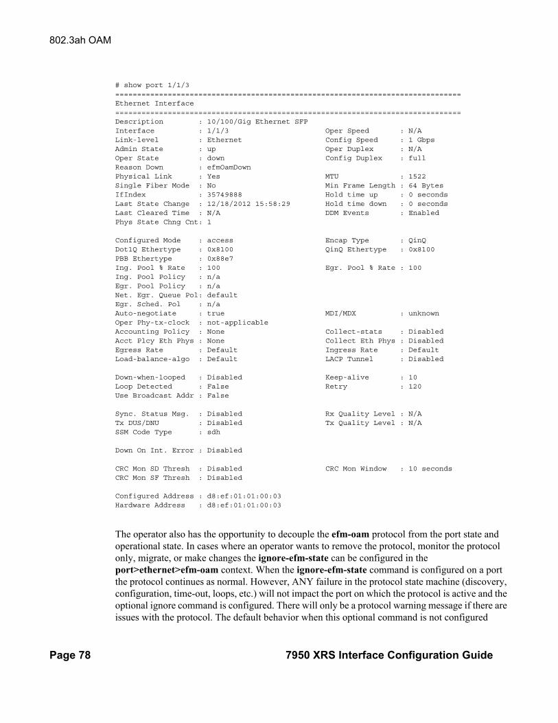
802.3ah OAM
Page 78 7950 XRS Interface Configuration Guide
# show port 1/1/3===============================================================================Ethernet Interface===============================================================================Description : 10/100/Gig Ethernet SFPInterface : 1/1/3 Oper Speed : N/ALink-level : Ethernet Config Speed : 1 GbpsAdmin State : up Oper Duplex : N/AOper State : down Config Duplex : fullReason Down : efmOamDownPhysical Link : Yes MTU : 1522Single Fiber Mode : No Min Frame Length : 64 BytesIfIndex : 35749888 Hold time up : 0 secondsLast State Change : 12/18/2012 15:58:29 Hold time down : 0 secondsLast Cleared Time : N/A DDM Events : EnabledPhys State Chng Cnt: 1
Configured Mode : access Encap Type : QinQDot1Q Ethertype : 0x8100 QinQ Ethertype : 0x8100PBB Ethertype : 0x88e7Ing. Pool % Rate : 100 Egr. Pool % Rate : 100Ing. Pool Policy : n/aEgr. Pool Policy : n/aNet. Egr. Queue Pol: defaultEgr. Sched. Pol : n/aAuto-negotiate : true MDI/MDX : unknownOper Phy-tx-clock : not-applicableAccounting Policy : None Collect-stats : DisabledAcct Plcy Eth Phys : None Collect Eth Phys : DisabledEgress Rate : Default Ingress Rate : DefaultLoad-balance-algo : Default LACP Tunnel : Disabled
Down-when-looped : Disabled Keep-alive : 10Loop Detected : False Retry : 120Use Broadcast Addr : False
Sync. Status Msg. : Disabled Rx Quality Level : N/ATx DUS/DNU : Disabled Tx Quality Level : N/ASSM Code Type : sdh
Down On Int. Error : Disabled
CRC Mon SD Thresh : Disabled CRC Mon Window : 10 secondsCRC Mon SF Thresh : Disabled
Configured Address : d8:ef:01:01:00:03Hardware Address : d8:ef:01:01:00:03
The operator also has the opportunity to decouple the efm-oam protocol from the port state and operational state. In cases where an operator wants to remove the protocol, monitor the protocol only, migrate, or make changes the ignore-efm-state can be configured in the port>ethernet>efm-oam context. When the ignore-efm-state command is configured on a port the protocol continues as normal. However, ANY failure in the protocol state machine (discovery, configuration, time-out, loops, etc.) will not impact the port on which the protocol is active and the optional ignore command is configured. There will only be a protocol warning message if there are issues with the protocol. The default behavior when this optional command is not configured

Interface Configuration
7950 XRS Interface Configuration Guide Page 79
means the port state will be affected by any efm-oam protocol fault or clear conditions. Adding and removing this optional ignore command will immediately represent the Port State and Oper State based on the active configuration. For example, if the ignore-efm-state is configured on a port that is exhibiting a protocol error that protocol error does not affect the port state or operational state and there is no Reason Down code. If the ignore-efm-state is removed from a port with an existing efm-oam protocol error, the port will transition to Link UP, Oper Down with the reason code efmOamDown.

802.3ah OAM
Page 80 7950 XRS Interface Configuration Guide
OAM Events
The Information OAMPDU is transmitted by each peer at the configured intervals. This OAMPDU performs keepalive and critical notification functions. Various local conditions are conveyed through the setting of the Flags field. The following Critical Link Event defined in IEEE 802.3 Section 57.2.10.1 are supported;
• Link Fault: The PHY has determined a fault has occurred in the receive direction of the local DTE
• Dying Gasp: An unrecoverable local failure condition has occurred
• Critical Event: An unspecified critical event has occurred
The local node can set an unset the various Flag fields based on the operational state of the port, shutdown or activation of the efm-oam protocol or locally raised events. These Flag fields maintain the setting for the continuance of a particular event. Changing port conditions, protocol state or operator intervention may impact the setting of these fields in the Information OAMPDU.
A peer processing the Information OAMPDU can take a configured action when one or more of these Flag fields are set. By default, receiving a set value for any of the Flag fields will cause the local port to enter the previous mentioned Link Up port state and an event will be logged. If this default behavior is not desired, the operator may choose to log the event without affecting the local port. This is configurable per Flag field using the options under config>port>ethernet>efm-oam>peer-rdi-rx.
Link Monitoring
The efm-oam protocol provides the ability to monitor the link for error conditions that may indicate the link is starting to degrade or has reached an error rate that exceeds acceptable threshold.
Link monitoring can be enabled for three types of frame errors; errored-frame, errored-frame-period and errored-frame-seconds. The errored-frame monitor is the number of frame errors compared to the threshold over a window of time. The errored-frame-period monitor is the number of frame errors compared to the threshold over a window of number of received packets. This window is checked once per second to see if the window parameter has been reached. The errored-frame-seconds monitor is the number of errored seconds compared to the threshold over a window of time. An errored second is any second with a single frame error.
An errored frame is counted when any frame is in error as determined by the Ethernet physical layer, including jabbers, fragments, FCS or CRC and runts. This excludes jumbo frames with a byte count higher than 9212, or any frame that is dropped by the phy layer prior to reaching the monitoring function.
Interface Configuration
7950 XRS Interface Configuration Guide Page 81
Each frame error monitor functions independently of other monitors. Each of monitor configuration includes an optional signal degrade threshold sd-threshold, a signal failure threshold sf-threshold, a window and the ability to communicate failure events to the peer by setting a Flag field in the Information OAMPDU or the generation of the Event Notification OAMPDU, event-notification. The parameters are uniquely configurable for each monitor.
A degraded condition is raised when the configured signal degrade sd-threshold is reached. This provides a first level log only action indicating a link could become unstable. This event does not affect the port state. The critical failure condition is raised when the configured sf-threshold is reached. By default, reaching the signal failure threshold will cause the port to enter the Link Up condition unless the local signal failure local-sf-action has been modified to a log-only action. Signal degrade conditions for a monitor in signal failed state will be suppressed until the signal failure has been cleared.
The initial configuration or the modification of either of the threshold values will take affect in the current window. When a threshold value for a monitor is modified, all active local events for that specific monitor will be cleared. The modification of the threshold acts the same as the clear command described later in this section.
Notification to the peer is required to ensure the action taken by the local port detecting the error and its peer are synchronized. If peers do not take the same action then one port may remain fully operational while the other enters a non-operational state. These threshold crossing events do not shutdown the physical link or cause the protocol to enter a non-operational state. The protocol and network element configuration is required to ensure these asymmetrical states do not occur. There are two options for exchanging link and event information between peers; Information OAMPDU and the Event Notification OAMPDU.
As discussed earlier, the Information OAMPDU conveys link information using the Flags field; dying gasp, critical link and link fault. This method of communication has a number of significant advantages over the Event Notification OAMPDU. The Information OAMPDU is sent at every configured transmit-interval. This will allow the most recent information to be sent between peers, a critical requirement to avoid asymmetrical forwarding conditions. A second major advantage is interoperability with devices that do not support Link Monitoring and vendor interoperability. This is the lowest common denominator that offers a robust communication to convey link event information. Since the Information OAMPDU is already being sent to maintain the peering relationship this method of communication adds no additional overhead. The local-sf-action options allow the dying gasp and critical event flags to be set in the Information OAMPDU when a signal failure threshold is reached. It is suggested that this be used in place of or in conjunction with Event Notification OAMPDU.
Event Notification OAMPDU provides a method to convey very specific information to a peer about various Link Events using Link Event TLVs. A unique Event Notification OAMPDU will be generated for each unique frame error event. The intension is to provide the peer with the Sequence Number, Event Type, Timestamp, and the local information that caused the generation of the OAMPDU; window, threshold, errors and error running total and event running total specific to the port.

802.3ah OAM
Page 82 7950 XRS Interface Configuration Guide
• Sequence Number: The unique identification indicating a new event.
• Window: The size of the unique measurement period for the error type. The window is only checked at the end. There is not mid-window checking.
• Threshold: The value of the configured sf-threshold
• Errors: The errors counted in that specific window
• Error Running Total: The number of errors accumulated for that event type since monitoring started and the protocol and port have been operational or a reset function has occurred
• Event Running Total: The number of events accumulated for that event type since the monitoring started and the protocol and port have been operational
By default, the Event Notification OAMPDU is generated by the network element detecting the signal failure event. The Event Notification OAMPDU is sent only when the initial frame event occurs. No Event Notification OAMPDU is sent when the conditions clears. A port that has been operationally affected as a result of a Link Monitoring frame error event must be recovered manually. The typical recovery method is to shutdown the port and no shutdown the port. This will clear all events on the port. Any function that affects the port state, physical fiber pull, soft or hard reset functions, protocol restarts, etc will also clear the all local and remote events on the affected node experiencing the operation. None of these frame errors recovery actions will cause the generation of the Event Notification OAMPDU. If the chosen recovery action is not otherwise recognized by the peer and the Information OAMPDU Flag fields have not been configured to maintain the current event state, there is a high probability that the ports will have different forwarding states, notwithstanding any higher level protocol verification that may be in place.
A burst of between one and five Event Notification OAMPDU packets may be sent. By default, only a single Event Notification OAMPDU is generated, but this value can be changed under the local-sf-action context. An Event Notification OAMPDU will only be processed if the peer had previously advertised the EV capability. The EV capability is an indication the remote peer supports link monitoring and may send the Event Notification OAMPDU.
The network element receiving the Event Notification OAMPDU will use the values contained in the Link event TLVs to determine if the remote node has exceeded the failure threshold. The locally configured action will determine how and if the local port is affected. By default, processing of the Event Notification OAMPDU is log only and does not affect the port state. By default, processing of the Information OAMPDU Flag fields is port affecting. When Event Notification OAMPDU has been configured as port affecting on the receiving node, action is only taken when errors are equal to or above the threshold and the threshold value is not zero. No action is taken when the errors value is less than the threshold or the threshold is zero.
Symbol error, errored-symbols, monitoring is also supported but requires specific hardware revisions and the appropriate code release. The symbol monitor differs from than the frame error monitors. Symbols represent a constant load on the Ethernet wire whether service frames are present or not. This means the optional signal degrade threshold sd-threshold has an additional purpose when configured as part of the symbol error monitor. When the signal degrade threshold

Interface Configuration
7950 XRS Interface Configuration Guide Page 83
is not configured, the symbol monitor acts similar to the frame error monitors, requiring manual intervention to clear a port that has been operationally affected by the monitor. When the optional signal degrade threshold is configured, it again represents the first level warning. However, it has an additional function as part of the symbol monitor. If a signal failure event has been raised, the configured signal degrade threshold becomes the equivalent to a lowering threshold. If a subsequent window does not reach the configured signal degrade threshold then the previous event will be cleared and the previously affected port will be returned to service without operator intervention. This return to service will automatically clear any previously set Information OAMPDU Flags fields set as a result of the signal failure threshold. The Event Notification OAMPDU will be generated with the symbol error Link TLV that contains an error count less than the threshold. This will indicate to the peer that initial problem has been resolved and the port should be returned to service.
The errored-symbol window is a measure of time that is automatically converted into the number of symbols for that specific medium for that period of time. The standard MIB entries “dot3OamErrSymPeriodWindowHi” and “dot3OamErrSymPeriodWindowLo” are marked as read-only instead of read-write. There is now way to directly configure these values. The configuration of the window will convert the time and program those two MIB values in an appropriate manner. Both the configured window and the number of symbols will be displayed under the show port port-id ethernet efm-oam command.
show port 1/1/1 ethernet efm-oam===============================================================================Ethernet Oam (802.3ah)===============================================================================Admin State : upOper State : link faultMode : activePdu Size : 1518Config Revision : 0Function Support : LBTransmit Interval : 1000 msMultiplier : 5Hold Time : 0Tunneling : falseLoop Detected : falseGrace Tx Enable : true (inactive)
No Peer Information Available
Loopback State : NoneLoopback Ignore Rx : IgnoreIgnore Efm State : falseLink Monitoring : disabled
Peer RDI Rx Critical Event : out-of-service Dying Gasp : out-of-service Link Fault : out-of-service Event Notify : log-only
Local SF Action Discovery Event Burst : 1 Ad Link Mon Cap : yes

802.3ah OAM
Page 84 7950 XRS Interface Configuration Guide
Port Action : out-of-service Dying Gasp : disabled Critical Event : disabled
Errored Frame Errored Frame Period Enabled : no Enabled : no Event Notify : enabled Event Notify : enabled SF Threshold : 10 SF Threshold : 1 SD Threshold : disabled (0) SD Threshold : disabled (0) Window : 10 ds Window : 1488095 frames
Errored Symbol Period Errored Frame Seconds Summary Enabled : no Enabled : no Event Notify : enabled Event Notify : enabled SF Threshold : 1 SF Threshold : 1 SD Threshold : disabled (0) SD Threshold : disabled (0) Window (time) : 10 ds Window : 600 ds Window (symbols) : 125000000===============================================================================Active Failure Ethernet OAM Event Logs===============================================================================Number of Logs : 0===============================================================================
===============================================================================Ethernet Oam Statistics=============================================================================== Input Output-------------------------------------------------------------------------------Information 0 0Loopback Control 0 0Unique Event Notify 0 0Duplicate Event Notify 0 0Unsupported Codes 0 0Frames Lost 0===============================================================================
A clear command “clear port port-id ethernet efm-oam events [local | remote]” has been added to clear port affecting events on the local node on which the command is issued. When the optional [local | remote] options are omitted, both local and remote events will be cleared for the specified port. This command is not specific to the link monitors as it clears all active events. When local events are cleared, all previously set Information OAMPDU Flag fields will be cleared regardless of the cause the event that set the Flag field.
In the case of symbol errors only, if Event Notification OAMPDU is enabled for symbol errors and a local symbol error signal failure event exists at the time of the clear, the Event Notification OAMPDU will be generate with an error count of zero and the threshold value reflecting the local signal failure threshold. The fact the error values is lower than threshold value indicates the local node is not in a signal failed state. The Event Notification OAMPDU is not generated in the case where the clear command is used to clear local frame error events. This is because frame error event monitors will only act on an Event Notification OAMPDU when the error value is higher than the threshold value, a lower value is ignored. As stated previously, there is no automatic return to service for frame errors.

Interface Configuration
7950 XRS Interface Configuration Guide Page 85
If the clear command is used to clear remote events, events conveyed to the local node by the peer, no notification is generated to the peer to indicate a clear function has been performed. Since the Event Notification OAMPDU is only sent when the initial event was raised, there is no further Event Notification and blackholes can result. If the Information OAMPDU Flag fields are used to ensure a constant refresh of information, the remote error will be reinstated as soon as the next Information OAMPDU arrives with the appropriate Flag field set.
Local and remote efm-oam port events are stored in the efm-oam event logs. These logs maintain and display active and cleared signal failure degrade events. These events are interacting with the efm-oam protocol. This logging is different than the time stamped events for information logging purposes included with the system log. To view these events, the event-log option has been added to the show port port-id ethernet efm-oam command. This includes the location, the event type, the counter information or the decoded Network Event TLV information, and if the port has been affected by this active event. A maximum of 12 port events will be retained. The first three indexes are reserved for the three Information Flag fields, dying gasp, critical link, and link fault. The other nine indexes will maintain the current state for the various error monitors in a most recent behavior and events can wrap the indexes, dropping the oldest event.
show port 1/2/1 ethernet efm-oam event-logs===============================================================================Active Failure Ethernet OAM Event Logs===============================================================================Log Index : 4Event Time Reference : 0d 07:01:45Location : remoteType : Errored FrameWindow : 50Threshold : 100Value : 100Running Total : 100Event Total : 1Port Affecting : yes-------------------------------------------------------------------------------Number of Logs : 1===============================================================================
===============================================================================Active Degraded Ethernet OAM Event Logs===============================================================================Number of Logs : 0===============================================================================
===============================================================================Cleared Failure Ethernet OAM Event Logs===============================================================================Log Index : 2Event Time Reference : 0d 06:59:08Location : remoteType : Dying GaspEvent Total : 16-------------------------------------------------------------------------------Number of Logs : 1===============================================================================

802.3ah OAM
Page 86 7950 XRS Interface Configuration Guide
===============================================================================Cleared Degraded Ethernet OAM Event Logs===============================================================================Number of Logs : 0===============================================================================
SRoS supports the vendor specific soft reset graceful recovery of efm-oam through the configuration of grace-tx-enable under the config>system>ethernet>efm-oam and the config>port>ethernet>efm-oam contexts. This feature is not enabled by default. When this functionality is enabled the efm-oam protocol does not enter a non-operational state when both nodes understand the grace function. The ports associated with the hardware that has successfully executed the soft reset will clear all local and remote events. The peer that understands the graceful restart procedure for efm-oam will clear all remote events that it received from the peer that undergone the soft reset. The local events will not be cleared on the peer that has not undergone soft reset. Again, the Information OAMPDU Flag fields are critical in propagating the local event to the peer. Remember, the Event Notification OAMPDU will not be sent because it is only sent on the initial raise.
In mixed environments where Link Monitoring is supported on one peer but not the other the following behavior is normal, assuming the Information OAMPDU has been enabled to convey the monitor fault event. The arriving Flag field fault will trigger the efm-oam protocol on the receiving unsupportive node to move from operational to “send local and remote”. The protocol on the supportive node that set the Flag field to convey the fault will enter the “send local and remote ok” state. The supportive node will maintain the Flag field setting until the condition has cleared. The protocol will recover to the operational state once the original event has cleared; assuming no other fault on the port is preventing the negotiation from progressing. If both nodes were supportive of the Link Monitoring process, the protocol would remained operational.
In summary, Link monitors can be configured for frame and symbol monitors (specific hardware only). By default, Link Monitoring and all monitors are shutdown. When the Link Monitoring function is enabled, the capability (EV) will be advertised. When a monitor is enabled, a default window size and a default signal failure threshold are activated. The local action for a signal failure threshold event is to shutdown the local port. Notification will be sent to the peer using the Event Notification OAMPDU. By default, the remote peer will not take any port action for the Event Notification OAMPDU. The reception will only be logged. It is suggested the operator evaluate the various defaults and configure the local-sf-action to set one of the Flag fields in the Information OAMPDU using the info-notifications command options when fault notification to a peer is required. Vendor specific TLVs and vendors specific OAMPDUs are just that, specific to that vendor. Non-ALU vendor specific information will not be processed.
Capability Advertising
A supported capability, sometimes requiring activation, will be advertised to the peer. The EV capability is advertisement when Link Monitoring is active on the port. This can be disabled using

Interface Configuration
7950 XRS Interface Configuration Guide Page 87
the optional command no link-monitoring under the config>port>ethernet>efm-oam>discovery>advertise-capabilities.
Remote Loopback
EFM OAM provides a link-layer frame loopback mode that can be remotely controlled.
To initiate remote loopback, the local EFM OAM client sends a loopback control OAM PDU by enabling the OAM remote-loopback command. After receiving the loopback control OAM PDU, the remote OAM client puts the remote port into local loopback mode.
To exit remote loopback, the local EFM OAM client sends a loopback control OAM PDU by disabling the OAM remote-loopback command. After receiving the loopback control OAM PDU, the remote OAM client puts the port back into normal forwarding mode.
Note that during remote loopback test operation, all frames except EFM OAM PDUs are dropped at the local port for the receive direction, where remote loopback is enabled. If local loopback is enabled, then all frames except EFM OAM PDUs are dropped at the local port for both the receive and transmit directions. This behavior may result in many protocols (such as STP or LAG) resetting their state machines.
Note that when a port is in loopback mode, service mirroring will not work if the port is a mirror-source or a mirror-destination.
802.3ah OAM PDU Tunneling for Epipe Service
The 7950 XRS routers support 802.3ah. Customers who subscribe to Epipe service treat the Epipe as a wire, so they demand the ability to run 802.3ah between their devices which are located at each end of the Epipe.
Note: This feature only applies to port-based Epipe SAPs because 802.3ah runs at port level not VLAN level. Hence, such ports must be configured as null encapsulated SAPs.
When OAM PDU tunneling is enabled, 802.3ah OAM PDUs received at one end of an Epipe are forwarded through the Epipe. 802.3ah can run between devices that are located at each end of the Epipe. When OAM PDU tunneling is disabled (by default), OAM PDUs are dropped or processed locally according to the efm-oam configuration (shutdown or no shutdown).
Note that by enabling 802.3ah for a specific port and enabling OAM PDU tunneling for the same port are mutually exclusive. Enforcement is performed on the CLI level.

MTU Configuration Guidelines
Page 88 7950 XRS Interface Configuration Guide
MTU Configuration Guidelines
Observe the following general rules when planning your service and physical MTU configurations:
• The 7950 XRS must contend with MTU limitations at many service points. The physical (access and network) port, service, and SDP MTU values must be individually defined.
• Identify the ports that will be designated as network ports intended to carry service traffic.
• MTU values should not be modified frequently.
• MTU values must conform to both of the following conditions:
→ The service MTU must be less than or equal to the SDP path MTU.→ The service MTU must be less than or equal to the access port (SAP) MTU.
Default MTU Values
Table 5 displays the default MTU values which are dependent upon the (sub-) port type, mode, and encapsulation.
*The default MTU for Ethernet ports other than Fast Ethernet is actually the lesser of 9212 and any MTU limitations imposed by hardware which is typically 16K.
Table 5: MTU Default Values
Port Type Mode Encap Type Default (bytes)
Ethernet access null 1514
Ethernet access dot1q 1518
Other Ethernet network — 9212*

Interface Configuration
7950 XRS Interface Configuration Guide Page 89
Modifying MTU Defaults
MTU parameters should be modified on the service level as well as the port level.
• The service-level MTU parameters configure the service payload (Maximum Transmission Unit – MTU) in bytes for the service ID overriding the service-type default MTU.
• The port-level MTU parameters configure the maximum payload MTU size for an Ethernet port or SONET/SDH SONET path (sub-port), or a channel that is part of a LAG.
The default MTU values should be modified to ensure that packets are not dropped due to frame size limitations. The service MTU must be less than or equal to both the SAP port MTU and the SDP path MTU values. When an SDP is configured on a network port using default port MTU values, the operational path MTU can be less than the service MTU. In this case, enter the show service sdp command to check the operational state. If the operational state is down, then modify the MTU value accordingly.
Configuration Example
In order for the maximum length service frame to successfully travel from a local ingress SAP to a remote egress SAP, the MTU values configured on the local ingress SAP, the SDP (GRE or MPLS), and the egress SAP must be coordinated to accept the maximum frame size the service can forward. For example, the targeted MTU values to configure for a distributed Epipe service (ALA-A and ALA-B) are displayed in Figure 10.
Figure 10: MTU Configuration Example
OSSG012
SAP
1/1/1
encap:
100
Network
2/1/1
SAP
4/1/1
encap:
null
Network
3/1/1
ALA-A ALA-B
Table 6: MTU Configuration Example Values
ALA-A ALA-B
Access (SAP) Network Network Access (SAP)
Port (slot/MDA/port) 1/1/1

MTU Configuration Guidelines
Page 90 7950 XRS Interface Configuration Guide
Since ALA-A uses Dot1q encapsulation, the SAP MTU must be set to 1518 to be able to accept a 1514 byte service frame (see Table 5 for MTU default values). Each SDP MTU must be set to at least 1514 as well. If ALA-A’s network port (2/1/1) is configured as an Ethernet port with a GRE SDP encapsulation type, then the MTU value of network ports 2/1/1 and 3/1/1 must each be at least 1556 bytes (1514 MTU + 28 GRE/Martini + 14 Ethernet). Finally, the MTU of ALA-B’s SAP (access port 4/1/1) must be at least 1514, as it uses null encapsulation.
Mode type dot1q network network null
MTU 1518 1556 1556 1514
Table 6: MTU Configuration Example Values (Continued)
Interface Configuration
7950 XRS Interface Configuration Guide Page 91
Deploying Preprovisioned Components
When a line card/CMA/MDAXCM/XMA is installed in a preprovisioned slot, the device detects discrepancies between the preprovisioned line card/CMA/MDAXCM/XMA type configurations and the types actually installed. Error messages display if there are inconsistencies and the card will not initialize.
When the proper preprovisioned line card/CMA/MDAXCM/XMA are installed into the appropriate chassis slot, alarm, status, and performance details will display.

Configuration Process Overview
Page 92 7950 XRS Interface Configuration Guide
Configuration Process Overview
Figure 11 displays the process to provision chassis slots, XCMs (cards), XMAs (MDAs), and ports.
Figure 11: Slot, XCM (card), XMA (mda), and Port Configuration and Implementation Flow
ENABLE
DESIGNATE THE SPECIFIC MDA TYPE FOR THE SLOT
START
CARD
CHASSIS
MDA
PORT
IDENTIFY PORT TO CONFIGURE
CONFIGURE LAG ATTRIBUTES (optional)
CONFIGURE NETWORK AND ACCESS PORTS
SPECIFY CHASSIS SLOT
DESIGNATE THE SPECIFIC CARD TYPE FOR THE SLOT
SLOT
LAG
CONFIGURE PORT PARAMETERS

Interface Configuration
7950 XRS Interface Configuration Guide Page 93
Configuration Notes
The following information describes provisioning caveats:
• If a card or MDA (XMA) type is installed in a slot provisioned for a different type, the card will not initialize.
• A card and MDA (XMA) installed in an unprovisioned slot remain administratively and operationally down until the card type and MDA (XMA) is specified.
• Ports cannot be provisioned until the slot, card and MDA (XMA) type are specified.

Configuration Notes
Page 94 7950 XRS Interface Configuration Guide

Interface Configuration
7950 XRS Interface Configuration Guide Page 95
Configuring Physical Ports with CLI
This section provides information to configure XCMs (cards), XMAs (MDAs), and ports.
Topics in this section include:
→ Predefining Entities on page 95→ Preprovisioning a Port on page 97→ Maximizing Bandwidth Use on page 98
• Basic Configuration on page 99
• Common Configuration Tasks on page 100
→ Configuring Ports on page 104→ Configuring LAG Parameters on page 111
• Common Configuration Tasks on page 100
→ Configuring XCMs (Cards) and XMAs (MDAs) on page 101→ Configuring Ports on page 104
− Configuring Port Pool Parameters on page 104
− Changing Hybrid-Buffer-Allocation on page 107
− Configuring Ethernet Port Parameters on page 108
− Configuring SONET/SDH Port Parameters on page 110
→ Configuring LAG Parameters on page 111
− Configuring BFD on LAG Links on page 111
• Service Management Tasks on page 113
→ Modifying or Deleting an XMA (MDA) on page 113→ Modifying a Card Type on page 114→ Deleting a Card on page 115→ Deleting Port Parameters on page 115
Predefining Entities
In order to initialize a card, the chassis slot, line card type, and XMA (MDA) type must match the preprovisioned parameters. In this context, preprovisioning means to configure the entity type (such as the line card type, MDA type, port, and interface) that is planned for a chassis slot, line card, or MDA. Preprovisioned entities can be installed but not enabled or the slots can be configured but remain empty until populated. Provisioning means that the preprovisioned entity is installed and enabled.
You can:
Interfaces
Page 96 7950 XRS Interface Configuration Guide
• Pre-provision ports and interfaces after the line card and XMA (MDA) types are specified.
• Install line cards in slots with no preconfiguration parameters specified. Once the card is installed, the card and XMA (MDA) types must be specified.
• Install a line card in a slot provisioned for a different card type (the card will not initialize). The existing card and XMA (MDA) configuration must be deleted and replaced with the current information.

Interface Configuration
7950 XRS Interface Configuration Guide Page 97
Preprovisioning a Port
Before a port can be configured, the slot must be preprovisoned with an allowed card type and the XMA (MDA) must be preprovisioned with an allowed XMA (MDA) type. Some recommendations to configure a port include:
• Ethernet
→ Configure an access port for customer facing traffic on which services are configured.
An encapsulation type may be specified in order to distinguish services on the port or channel. Encapsulation types are not required for network ports.
To configure an Ethernet access port, refer to on page 108.

Interfaces
Page 98 7950 XRS Interface Configuration Guide
Maximizing Bandwidth Use
Once ports are preprovisioned, Link Aggregation Groups (LAGs) can be configured to increase the bandwidth available between two nodes. All physical links or channels in a given LAG/bundle combine to form one logical connection. A LAG/bundle also provides redundancy in case one or more links that participate in the LAG/bundle fail.

Interface Configuration
7950 XRS Interface Configuration Guide Page 99
Basic Configuration
The most basic configuration must have the following:
• Identify chassis slot.
• Specify line card type (must be an allowed card type).
• Identify XMA (MDA) slot.
• Specify XMA (MDA) (must be an allowed XMA/MDA type).
• Identify specific port to configure.
The following example displays some card configurations:
A:7950 XRS-20# configure card 1A:7950 XRS-20>config>card# info---------------------------------------------- card-type xcm-x20 mda 1 mda-type cx20-10g-sfp no shutdown exit mda 2 mda-type cx2-100g-cfp no shutdown exit no shutdown----------------------------------------------
Interfaces
Page 100 7950 XRS Interface Configuration Guide
Common Configuration Tasks
The following sections are basic system tasks that must be performed.
• Configuring XCMs (Cards) and XMAs (MDAs) on page 101
→ Configuring XMA Access and Network Pool Parameters on page 103
• Configuring Ports on page 104
→ Configuring Port Pool Parameters on page 104→ Configuring Ethernet Port Parameters on page 108→ Configuring SONET/SDH Port Parameters on page 110
• Configuring LAG Parameters on page 111
• Service Management Tasks on page 113

Interface Configuration
7950 XRS Interface Configuration Guide Page 101
Configuring XCMs (Cards) and XMAs (MDAs)
Card configurations include a chassis slot designation.
The following example displays a card and XMA (MDA) configuration:
A:7950 XRS-20# configure card 1A:7950 XRS-20>config>card# info---------------------------------------------- card-type xcm-x20 mda 1 mda-type cx20-10g-sfp no shutdown exit mda 2 mda-type cx2-100g-cfp no shutdown exit no shutdown----------------------------------------------
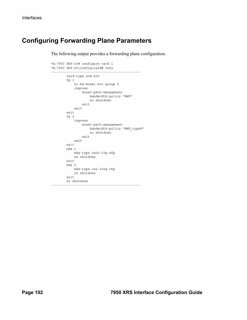
Interfaces
Page 102 7950 XRS Interface Configuration Guide
Configuring Forwarding Plane Parameters
The following output provides a forwarding plane configuration.
*A:7950 XRS-20# configure card 1
*A:7950 XRS-20>config>card# info---------------------------------------------- card-type xcm-x20 fp 1 hi-bw-mcast-src group 0 ingress mcast-path-management bandwidth-policy "BWP" no shutdown exit exit exit fp 2 ingress mcast-path-management bandwidth-policy "BWP_typeF" no shutdown exit exit exit mda 1 mda-type cx20-10g-sfp no shutdown exit mda 2 mda-type cx2-100g-cfp no shutdown exit no shutdown----------------------------------------------

Interface Configuration
7950 XRS Interface Configuration Guide Page 103
Configuring XMA Access and Network Pool Parameters
XMA-level pools are used by ingress network queues. Network policies can be applied (optional) to create and edit QoS pool resources on egress network ports, channels, and ingress XMAs. Network-queue and slope policies are configured in the config>qos context.
The following example displays an XMA pool configuration:
A:ALA-B>config>card>mda# info---------------------------------------------- mda-type cx20-10g-sfp network egress pool slope-policy "B" exit exit exit access ingress pool resv-cbs 50 slope-policy "A" exit exit exit----------------------------------------------A:ALA-B>config>card>mda#

Interfaces
Page 104 7950 XRS Interface Configuration Guide
Configuring Ports
This section provides the CLI syntax and examples to configure the following:
• Configuring Port Pool Parameters on page 104
• Changing Hybrid-Buffer-Allocation on page 107
• Configuring Ethernet Port Parameters on page 108
• Configuring SONET/SDH Port Parameters on page 110
Configuring Port Pool Parameters
The buffer space is portioned out on a per port basis. Each port gets an amount of buffering which is its fair-share based on the port’s bandwidth compared to the overall active bandwidth.
This mechanism takes the buffer space available and divides it into a portion for each port based on the ports active bandwidth relative to the amount of active bandwidth for all ports associated with the buffer space. An active port is considered to be any port that has an active queue associated. Once a queue is created for the port, the system will allocate the appropriate amount of buffer space to the port. This process is independently performed for both ingress and egress.
Normally, the amount of active bandwidth is considered as opposed to total potential bandwidth for the port when determining the ports fair share. If a port is channelized and not all bandwidth is allocated, only the bandwidth represented by the configured channels with queues configured is counted towards the bandwidth represented by the port. Based on the above, the number of buffers managed by a port may change due to queue creation and deletion.
After the active bandwidth is calculated for the port, the result may be modified through the use of the ‘ing-percentage-of-rate’ and ‘egr-percent-of-rate’ commands. The default value of each is 100% which allows the system to use all of the ports active bandwidth when deciding the relative amount of buffer space to allocate to the port. When the value is explicitly modified, the active bandwidth on the port is changed according to the specified percentage. If a value of 50% is given, the ports active bandwidth will be multiplied by 5, if a value of 150% is given, the active bandwidth will be multiplied by 1.5. This capability is independent of named pool mode. The ports rate percentage parameters may be modified at any time.
Examples:
1. To modify (in this example, to double) the size of buffer allocated on ingress for a port:
CLI Syntax: B:SR7-10# configure port 1/2/1 modify-buffer-allocation-rate ing-percentage-of-rate 200
2. To modify (in this example, to double) the size of buffer allocated on ingress for a port:
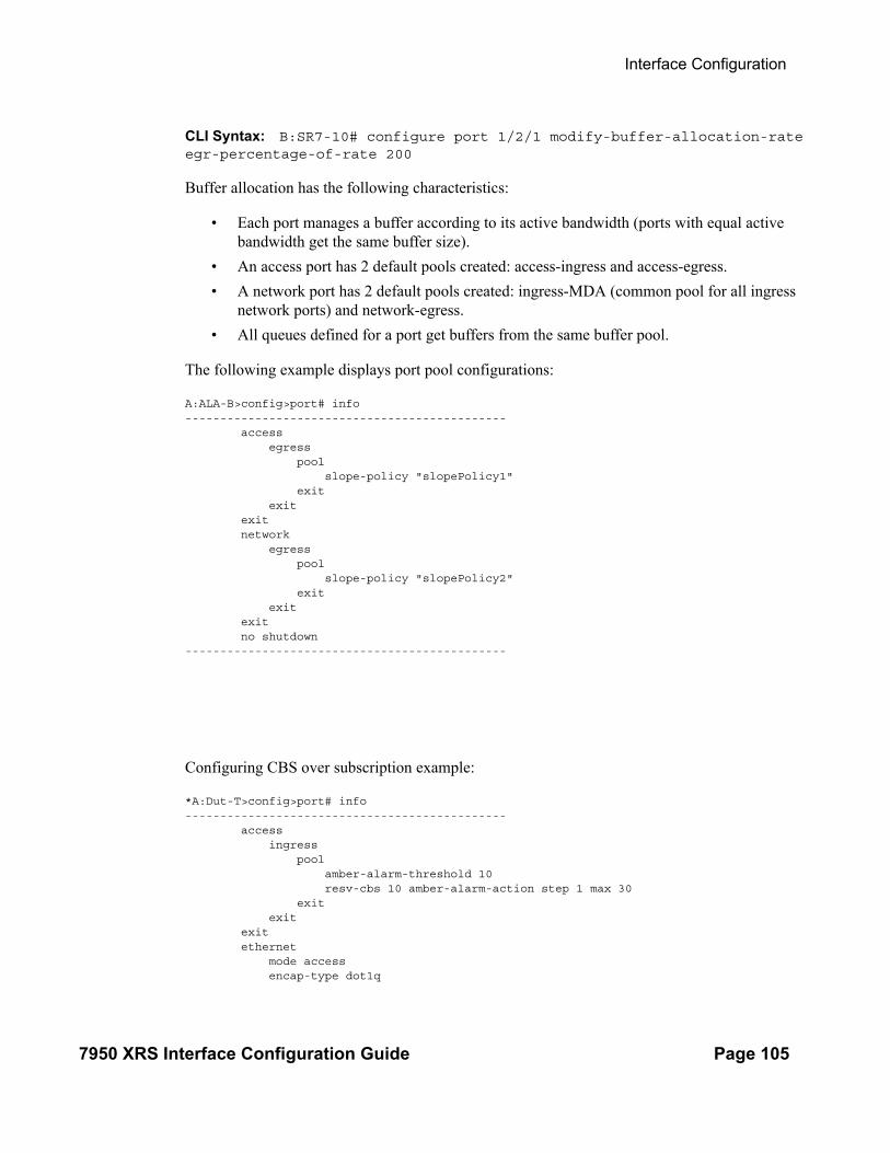
Interface Configuration
7950 XRS Interface Configuration Guide Page 105
CLI Syntax: B:SR7-10# configure port 1/2/1 modify-buffer-allocation-rate egr-percentage-of-rate 200
Buffer allocation has the following characteristics:
• Each port manages a buffer according to its active bandwidth (ports with equal active bandwidth get the same buffer size).
• An access port has 2 default pools created: access-ingress and access-egress.
• A network port has 2 default pools created: ingress-MDA (common pool for all ingress network ports) and network-egress.
• All queues defined for a port get buffers from the same buffer pool.
The following example displays port pool configurations:
A:ALA-B>config>port# info ---------------------------------------------- access egress pool slope-policy "slopePolicy1" exit exit exit network egress pool slope-policy "slopePolicy2" exit exit exit no shutdown----------------------------------------------
Configuring CBS over subscription example:
*A:Dut-T>config>port# info ---------------------------------------------- access ingress pool amber-alarm-threshold 10 resv-cbs 10 amber-alarm-action step 1 max 30 exit exit exit ethernet mode access encap-type dot1q

Interfaces
Page 106 7950 XRS Interface Configuration Guide
exit no shutdown

Interface Configuration
7950 XRS Interface Configuration Guide Page 107
Changing Hybrid-Buffer-Allocation
The following example displays a hybrid-buffer-allocation value change (from default) for ingress. In this example, the network-egress buffer pool is two times the size of the access-egress.
A:SR>config>port>hybrid-buffer-allocation# info ----------------------------------------------egr-weight access 20 network 40

Interfaces
Page 108 7950 XRS Interface Configuration Guide
Configuring Ethernet Port Parameters
Ethernet Network Port
A network port is network facing and participates in the service provider transport or infrastructure network processes.
The following example displays a network port configuration:
A:ALA-B>config>port# info ---------------------------------------------- description "Ethernet network port" ethernet exit no shutdown----------------------------------------------A:ALA-B>config>port#
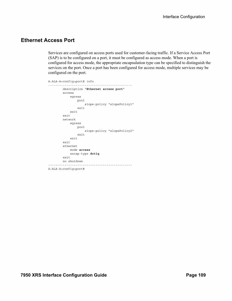
Interface Configuration
7950 XRS Interface Configuration Guide Page 109
Ethernet Access Port
Services are configured on access ports used for customer-facing traffic. If a Service Access Port (SAP) is to be configured on a port, it must be configured as access mode. When a port is configured for access mode, the appropriate encapsulation type can be specified to distinguish the services on the port. Once a port has been configured for access mode, multiple services may be configured on the port.
A:ALA-A>config>port# info---------------------------------------------- description "Ethernet access port" access egress pool slope-policy "slopePolicy1" exit exit exit network egress pool slope-policy "slopePolicy2" exit exit exit ethernet mode access encap-type dot1q exit no shutdown----------------------------------------------A:ALA-A>config>port#
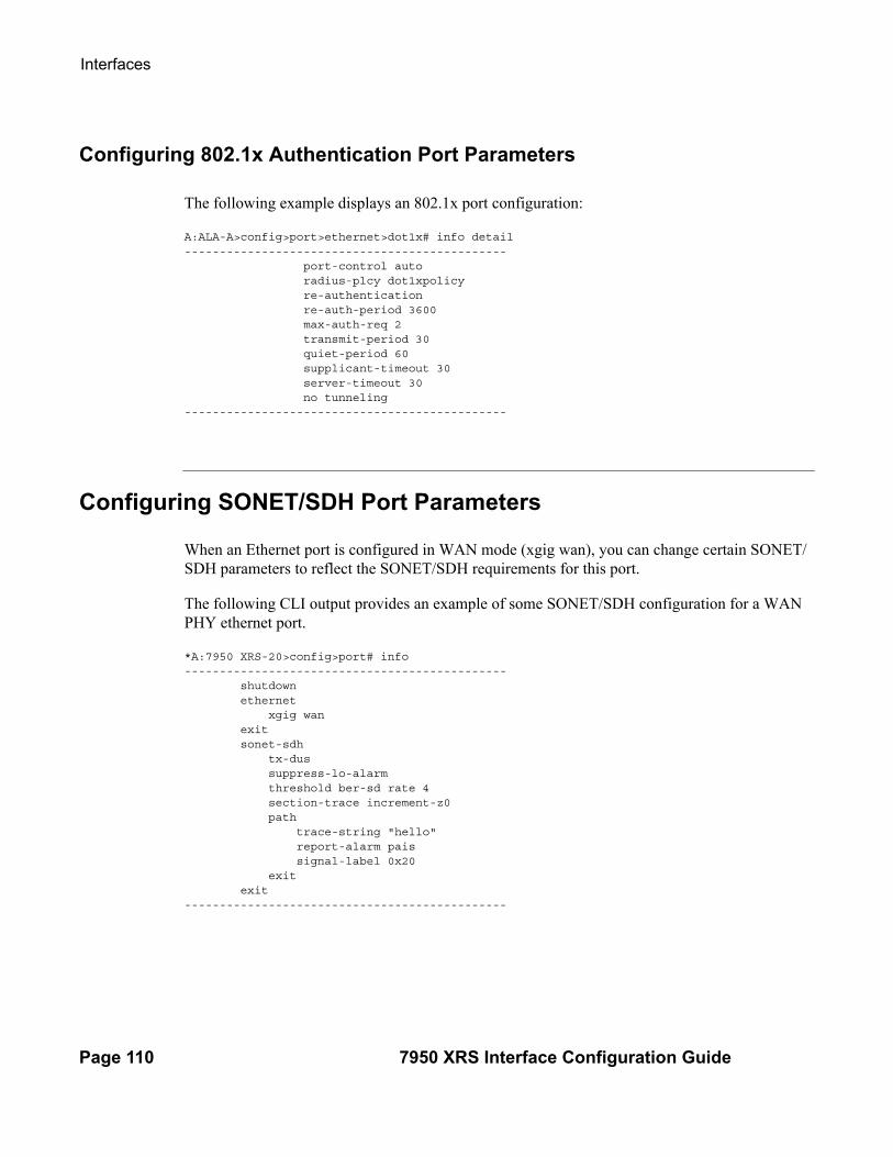
Interfaces
Page 110 7950 XRS Interface Configuration Guide
Configuring 802.1x Authentication Port Parameters
The following example displays an 802.1x port configuration:
A:ALA-A>config>port>ethernet>dot1x# info detail---------------------------------------------- port-control auto radius-plcy dot1xpolicy re-authentication re-auth-period 3600 max-auth-req 2 transmit-period 30 quiet-period 60 supplicant-timeout 30 server-timeout 30 no tunneling----------------------------------------------
Configuring SONET/SDH Port Parameters
When an Ethernet port is configured in WAN mode (xgig wan), you can change certain SONET/SDH parameters to reflect the SONET/SDH requirements for this port.
The following CLI output provides an example of some SONET/SDH configuration for a WAN PHY ethernet port.
*A:7950 XRS-20>config>port# info---------------------------------------------- shutdown ethernet xgig wan exit sonet-sdh tx-dus suppress-lo-alarm threshold ber-sd rate 4 section-trace increment-z0 path trace-string "hello" report-alarm pais signal-label 0x20 exit exit----------------------------------------------
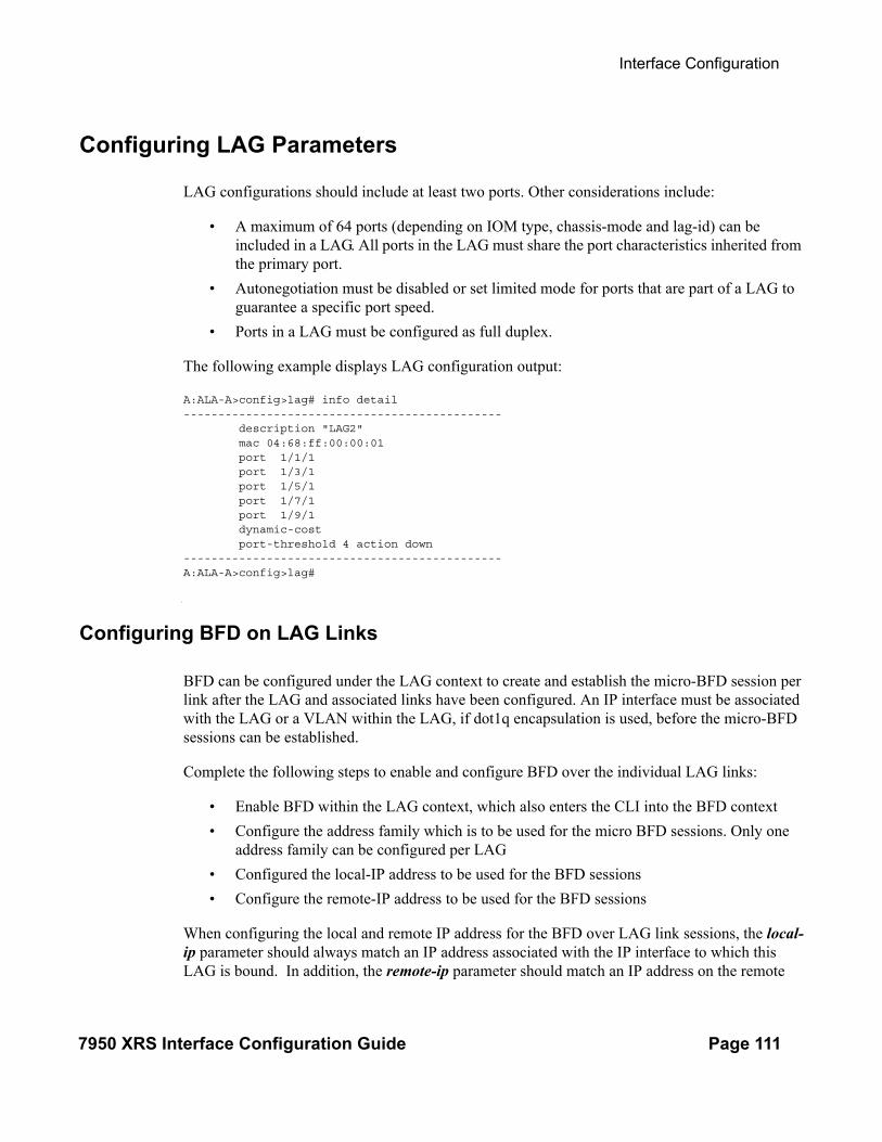
Interface Configuration
7950 XRS Interface Configuration Guide Page 111
Configuring LAG Parameters
LAG configurations should include at least two ports. Other considerations include:
• A maximum of 64 ports (depending on IOM type, chassis-mode and lag-id) can be included in a LAG. All ports in the LAG must share the port characteristics inherited from the primary port.
• Autonegotiation must be disabled or set limited mode for ports that are part of a LAG to guarantee a specific port speed.
• Ports in a LAG must be configured as full duplex.
The following example displays LAG configuration output:
A:ALA-A>config>lag# info detail---------------------------------------------- description "LAG2" mac 04:68:ff:00:00:01 port 1/1/1 port 1/3/1 port 1/5/1 port 1/7/1 port 1/9/1 dynamic-cost port-threshold 4 action down----------------------------------------------A:ALA-A>config>lag#
Configuring BFD on LAG Links
BFD can be configured under the LAG context to create and establish the micro-BFD session per link after the LAG and associated links have been configured. An IP interface must be associated with the LAG or a VLAN within the LAG, if dot1q encapsulation is used, before the micro-BFD sessions can be established.
Complete the following steps to enable and configure BFD over the individual LAG links:
• Enable BFD within the LAG context, which also enters the CLI into the BFD context
• Configure the address family which is to be used for the micro BFD sessions. Only one address family can be configured per LAG
• Configured the local-IP address to be used for the BFD sessions
• Configure the remote-IP address to be used for the BFD sessions
When configuring the local and remote IP address for the BFD over LAG link sessions, the local-ip parameter should always match an IP address associated with the IP interface to which this LAG is bound. In addition, the remote-ip parameter should match an IP address on the remote
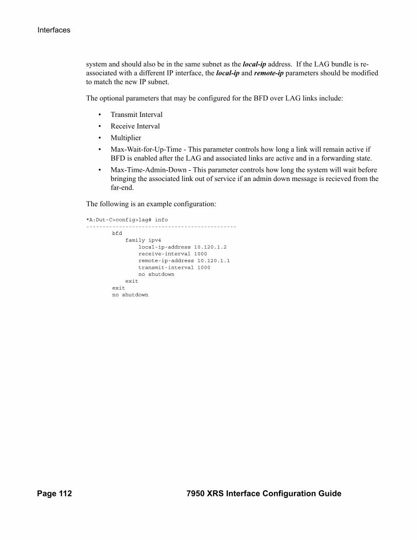
Interfaces
Page 112 7950 XRS Interface Configuration Guide
system and should also be in the same subnet as the local-ip address. If the LAG bundle is re-associated with a different IP interface, the local-ip and remote-ip parameters should be modified to match the new IP subnet.
The optional parameters that may be configured for the BFD over LAG links include:
• Transmit Interval
• Receive Interval
• Multiplier
• Max-Wait-for-Up-Time - This parameter controls how long a link will remain active if BFD is enabled after the LAG and associated links are active and in a forwarding state.
• Max-Time-Admin-Down - This parameter controls how long the system will wait before bringing the associated link out of service if an admin down message is recieved from the far-end.
The following is an example configuration:
*A:Dut-C>config>lag# info ---------------------------------------------- bfd family ipv4 local-ip-address 10.120.1.2 receive-interval 1000 remote-ip-address 10.120.1.1 transmit-interval 1000 no shutdown exit exit no shutdown

Interface Configuration
7950 XRS Interface Configuration Guide Page 113
Service Management Tasks
This section discusses basic procedures of the following service management tasks:
• Modifying a Card Type on page 114
• Deleting a Card on page 115
• Deleting Port Parameters on page 115
Modifying or Deleting an XMA (MDA)
To change an XMA/MDA type already provisioned for a specific slot/card, first you must shut down the slot/MDA/port configuration and then delete the MDA from the configuration.
Note: To modify or delete XMAs, use the MDA command structure.
Use the following CLI syntax to modify an MDA:
CLI Syntax: config> port port-idshutdown
CLI Syntax: config> card slot-numbershutdown
[no] mda mda-number[no] mda-type mda-type[no] hi-bw-mcast-src [alarm] [group group-id]shutdown

Interfaces
Page 114 7950 XRS Interface Configuration Guide
Modifying a Card Type
In order to modify the card type already provisioned for a specific slot, you must shutdown existing port configurations and shutdown and remove all XMA configurations.
Note: You must reset the IOM after changing the MDA type from MS-ISA to any other MDA type.
Use the following CLI syntax to modify a card type already provisioned for a specific slot:
CLI Syntax: config> port port-id[no] shutdown
CLI Syntax: config> card slot-numbermda mda-number
[no] mda-type mda-type[no] shutdown

Interface Configuration
7950 XRS Interface Configuration Guide Page 115
Deleting a Card
In order to delete the card type provisioned for a specific slot, you must shutdown existing port configurations and shutdown and remove all XMA configurations. Use the following CLI syntax to delete a card provisioned for a specific slot:
CLI Syntax: config> port port-idshutdown
CLI Syntax: config> card slot-numbercard-type card-typemda mda-number
no mda-type mda-typeno shutdown
Deleting Port Parameters
Use the following CLI syntax to delete a port provisioned for a specific card:
CLI Syntax: config>port port-idshutdownno port port-id

Interfaces
Page 116 7950 XRS Interface Configuration Guide

Command Reference
7950 XRS Interface Configuration Guide Page 117
Card, MDAXMA, and Port Command Reference
Command Hierarchies
Card and MDA Configuration Commands
• Hardware Commands on page 118
→ Card Commands on page 118→ MDAXMA/MDA Commands on page 118→ MCM Commands on page 118→ Forwarding Plane (FP) Commands on page 121
• Port Configuration Commands on page 124
• Port APS Commands on page 127
• Ethernet Commands on page 128
• Multilink Bundle Commands on page 135
• SONET/SDH Commands on page 137
• SONET Path ATM Commands on page 137
• TDM Commands on page 140
• DS1 Commands on page 140
• DS3 Commands on page 142
• E1 Commands on page 143
• E3 Commands on page 145
• LAG Commands on page 147
• Ethernet Tunnel Commands on page 150
• Multi-Chassis Redundancy Commands on page 151
• Show Commands on page 153
• Clear Commands on page 155
• Debug Commands on page 156
• Tools Commands on page 156

Interfaces
Page 118 7950 XRS Interface Configuration Guide
Hardware Commands
Card Commands
configconfig
— [no] card slot-number— [no] card slot-number
— capability {sr | ess} [now]— card-type card-type— no card-type— [no] fail-on-error— [no] named-pool-mode
MCM Commands
— [no] mcm mcm-slot— mcm-type mcm-type— no mcm-type— [no] shutdown
MDAXMA/MDA Commands
— [no] card slot-number — [no] mda mda-slot
— access— egress
— [no] pool [name]— amber-alarm-threshold percentage— no amber-alarm-threshold— red-alarm-threshold percentage— no red-alarm-threshold— resv-cbs percent-or-default amber-alarm-action
step percent max [1..100]— resv-cbs percent-or-default— no resv-cbs— slope-policy name— no slope-policy
— ingress— [no] pool [name]
— amber-alarm-threshold percentage— no amber-alarm-threshold— red-alarm-threshold percentage— no red-alarm-threshold— resv-cbs percent-or-default amber-alarm-action
step percent max [1..100]— resv-cbs percent-or-default— no resv-cbs— slope-policy name— no slope-policy
— clock-mode adaptive— clock-mode differential [timestamp-freq {19440 | 77760 | 103680}]— egress— hi-bw-mcast-src [alarm] [group group-id]— no hi-bw-mcast-src— egress-xpl
— threshold threshold

Command Reference
7950 XRS Interface Configuration Guide Page 119
— window window— [no] fail-on-error— ingress
— mcast-path-management— ancillary-override
— path-limit megabits-per-second— no path-limit
— bandwidth-policy policy-name— no bandwidth-policy— primary-override
— path-limit megabits-per-second— no path-limit
— secondary-override— path-limit megabits-per-second— no path-limit
— [no] shutdown— scheduler-policy hsmda-scheduler-policy-name— no scheduler-policy
— ingress-xpl— threshold threshold— window window
— mda-type mda-type— no mda-type— power-priority-level 1..200— named-pool-mode
— egress— named-pool-policy policy-name— no named-pool-policy
— ingress— named-pool-policy policy-name— no named-pool-policy
— network— egress
— [no] pool [name]— amber-alarm-threshold percentage— no amber-alarm-threshold— red-alarm-threshold percentage— no red-alarm-threshold— resv-cbs percent-or-default amber-alarm-action
step percent max [1..100]— resv-cbs percent-or-default— no resv-cbs— slope-policy name— no slope-policy
— ingress— [no] pool [name]
— amber-alarm-threshold percentage— no amber-alarm-threshold— red-alarm-threshold percentage— no red-alarm-threshold— resv-cbs percent-or-default amber-alarm-action
step percent max [1..100]— resv-cbs percent-or-default— no resv-cbs— slope-policy name

Interfaces
Page 120 7950 XRS Interface Configuration Guide
— no slope-policy— queue-policy name— no queue-policy
— [no] shutdown— [no] sync-e
— [no] shutdown— [no] named-pool-mode [now]
Power Commands
config— system
— power-management— mode [none|basic|advanced]— power-safety-level %— power safety-alert value in watts— peq peq-slot
— [no] peq-type peq-type— [no] shutdown
Virtual Scheduler Commands
— [no] card slot-number — virtual-scheduler-adjustment
— rate-calc-min-int [fast-queue percent-of-default] [slow-queue percent-of-default]
— no rate-calc-min-int— sched-run-min-int percent-of-default— no sched-run-min-int— task-scheduling-int percent-of-default— no task-scheduling-int— slow-queue-thresh kilobits-per-second— no slow-queue-thresh

Command Reference
7950 XRS Interface Configuration Guide Page 121
Forwarding Plane (FP) Commands
config— card
— fp [fp-number]— dist-cpu-protection policy-name— no dist-cpu-protection— egress
— wred-queue-control— buffer-allocation min percentage max percentage— no buffer-allocation— resv-cbs min percentage max percentage— no resv-cbs— [no] shutdown— slope-policy slope-policy-name— no slope-policy
— hi-bw-mcast-src [alarm] [group group-id] [default-paths-only] — no hi-bw-mcast-src — ingress
— access— queue-group queue-group-name instance instance-id
[create]— accounting-policy policy-name— no accounting-policy— [no] collect-stats— description long-description-string— no description— policer-control-policy policy-name— no policer-control-policy
— max-rate {rate | max}— priority-mbs-thresholds
— min-thresh-separation size [bytes | kilo-bytes]
— [no] priority level— mbs-contribution [bytes | kilobytes]
— [no] policer-override— policer policer-id [create]— no policer policer-id— stat-mode {no-stats | minimal | offered-profile-
no-cir | offered-priority-no-cir | offered-limited-profile-cir | offered-profile-cir | offered-priority-cir|offered-total-cir | offered-profile-capped-cir | offered-limited-capped-cir}
— no stat-mode— rate {max | kilobits-per-second} [cir {max | kilo-
bits-per-second}]— no rate— mbs {size [bytes | kilobytes] | default}— no mbs— max or 0—2000000000cbs {size [bytes | kilobytes]
| default}— no max or 0—2000000000cbs— packet-byte-offset {add bytes | subtract bytes}— no packet-byte-offset
— ingress-buffer-allocation hundredths-of-a-percent

Interfaces
Page 122 7950 XRS Interface Configuration Guide
— no ingress-buffer-allocation— mcast-path-management
— bandwidth-policy policy-name— no bandwidth-policy— [no] shutdown
— network— queue-group queue-group-name instance instance-id— no queue-group
— accounting-policy acct-policy-id— no accounting-policy— [no] collect-stats— description description-string— no description— policer-control-policy policy-name— no policer-control-policy
— priority-mbs-thresholds— min-thresh-separation size [bytes | kilo-
bytes]— [no] priority level— mbs-contribution size [bytes | kilobytes]
— [no] policer-override— policer policer-id [create]— no policer policer-id— stat-mode {no-stats | minimal | offered-profile-
no-cir | offered-priority-no-cir | offered-limited-profile-cir | offered-profile-cir | offered-priority-cir|offered-total-cir | offered-profile-capped-cir | offered-limited-capped-cir}
— no stat-mode— rate {max | kilobits-per-second} [cir {max | kilo-
bits-per-second}]— no rate— mbs {size [bytes | kilobytes] | default}— no mbs— max or 0—2000000000cbs {size [bytes | kilobytes]
| default}— no max or 0—2000000000cbs— packet-byte-offset{add bytes | subtract bytes}— packet-byte-offset
— [no] stable-pool-sizing— mda
— ingress— mcast-path-management
— ancillary-override— path-limit megabits-per-second— no path-limit
— bandwidth-policy policy-name— no bandwidth-policy— primary-override
— path-limit megabits-per-second— no path-limit
— secondary-override— path-limit megabits-per-second— no path-limit
— [no] shutdown
Command Reference
7950 XRS Interface Configuration Guide Page 123
tools — dump
— mcast-path-mgr — cpm

Interfaces
Page 124 7950 XRS Interface Configuration Guide
Port Configuration Commands
config Port Configuration Commands — port {port-id | bundle-id | bpgrp-id | aps-id}port-id
— no port {bundle-id | bpgrp-id | aps-id}port-id— access
— egress— channel
— [no] pool [name]— resv-cbs percent-or-default— no resv-cbs— slope-policy name— no slope-policy
— [no] pool [name]— amber-alarm-threshold percentage— no amber-alarm-threshold— red-alarm-threshold percentage— no red-alarm-threshold— resv-cbs percent-or-default amber-alarm-action step percent
max [1..100]— resv-cbs percent-or-default— no resv-cbs— slope-policy name— no slope-policy
— ingress— [no] pool [name]
— amber-alarm-threshold percentage— no amber-alarm-threshold— red-alarm-threshold percentage— no red-alarm-threshold— resv-cbs percent-or-default amber-alarm-action step percent
max [1..100]— resv-cbs percent-or-default— no resv-cbs— slope-policy name— no slope-policy
— [no] ddm-events— description long-description-string— no description— dwdm
— amplifier— report-alarms [ild] [tmp] [mth] [mtl] [los] [lop] [com]
— channel channel— coherent
— channel channel— cpr-window-size window-size— dispersion dispersion— mode {automatic|manual}— report-alarms [modflt] [mod] [netrx] [nettx] [hosttx]— rx-los-thresh threshold— sweep start dispersion-start end dispersion-end— target-power power
— [no] rxdtv-adjust— tdcm

Command Reference
7950 XRS Interface Configuration Guide Page 125
— channel— dispersion dispersion— mode {automatic | manual}— report-alarms [nrdy] [mth] [mtl] [unlck] [tlim] [einv] [com]— sweep start dispersion-start end dispersion-end
— wavetracker— encode wave-key key2 wave-key— no encode— [no] power-control
— target-power dBm— [no] report-alarm [encode-fail] [encode-degrade] [power-
fail] [power-degrade] [power-high] [power-low]— xgig {lan | wan}
— [no] gfp-f— hybrid-buffer-allocation
— ing-weight access access-weight network network-weight— no ing-weight— egr-weight access access-weight network network-weight— no egr-weight
— modify-buffer-allocation-rate— ing-percentage-of-rate rate-percentage— no ing-percentage-of-rate— egr-percentage-of-rate rate-percentage— no egr-percentage-of-rate
— named-pool-mode— egress
— named-pool-policy policy-name— no named-pool-policy
— ingress— named-pool-policy policy-name— no named-pool-policy
— network— egress
— [no] pool [name]— amber-alarm-threshold percentage— no amber-alarm-threshold— red-alarm-threshold percentage— no red-alarm-threshold— resv-cbs percent-or-default amber-alarm-action step percent
max [1..100]— resv-cbs percent-or-default— no resv-cbs— slope-policy name— no slope-policy
— [no] otu— [no] async-mapping— fec {enhanced | g709}— no fec — otu2-lan-data-rate {11.049 | 11.0957}— pm-tti
— expected auto-generated— expected bytes byte [byte...(up to 64 max)]— expected string identifier— expected use-rx— mismatch-reaction {squelch-rx}
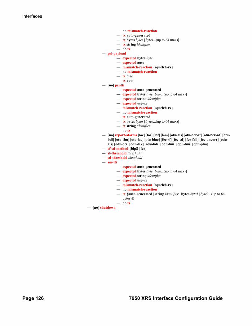
Interfaces
Page 126 7950 XRS Interface Configuration Guide
— no mismatch-reaction— tx auto-generated— tx bytes bytes [bytes...(up to 64 max)]— tx string identifier— no tx
— psi-payload— expected bytes byte— expected auto— mismatch-reaction {squelch-rx}— no mismatch-reaction— tx byte— tx auto
— [no] psi-tti— expected auto-generated— expected bytes byte [byte...(up to 64 max)]— expected string identifier— expected use-rx— mismatch-reaction {squelch-rx}— no mismatch-reaction— tx auto-generated— tx bytes bytes [bytes...(up to 64 max)]— tx string identifier— no tx
— [no] report-alarms [loc] [los] [lof] [lom] [otu-ais] [otu-ber-sf] [otu-ber-sd] [otu-bdi] [otu-tim] [otu-iae] [otu-biae] [fec-sf] [fec-sd] [fec-fail] [fec-uncorr] [odu-ais] [odu-oci] [odu-lck] [odu-bdi] [odu-tim] [opu-tim] [opu-plm]
— sf-sd-method {bip8 | fec}— sf-threshold threshold— sd-threshold threshold— sm-tti
— expected auto-generated— expected bytes byte [byte...(up to 64 max)]— expected string identifier— expected use-rx— mismatch-reaction {squelch-rx}— no mismatch-reaction— tx {auto-generated | string identifier | bytes byte1 [byte2...(up to 64
bytes)]}— no tx
— [no] shutdown

Command Reference
7950 XRS Interface Configuration Guide Page 127
Port APS Commands
config— [no] port {aps-id}
— aps— advertise-interval advertise-interval— no advertise-interval— hold-time hold-time— no hold-time— hold-time-aps [lsignal-failure sf-time][lsignal-degrade sd-time]— no hold-time-aps— no — [no] k-byte-tx (R8.0 R4) [protecting | none | both] — neighbor ip-address— no neighbor— protect-circuit port-id— no protect-circuit— rdi-alarms [suppress | circuit]— revert-time minutes— no revert-time — switching-mode {bi-directional | uni-directional | uni-1plus1}— working-circuit port-id [number number]— no working-circuit— wtr-annexb minute

Interfaces
Page 128 7950 XRS Interface Configuration Guide
Ethernet Commands
config — [no] port {port-id}
— ethernet— access
— egress— queue-group queue-group-name [instance instance-id] — no queue-group queue-group-name
— accounting-policy acct-policy-id— no accounting-policy— [no] agg-rate
— [no] limit-unused-bandwidth— [no] queue-frame-based-accounting— rate {max | rate}— no rate
— [no] collect-stats— description description-string— no description— queue-overrides
— queue queue-id [create]— no queue queue-id
— parent [[weight weight] [cir-weight cir-weight]]
— no parent— adaptation-rule [pir {max | min | closest}]
[cir {max | min | closest}]— no adaptation-rule— burst-limit {default | size [byte | kilo-
byte]}— no burst-limit— cbs size-in-kbytes— no cbs— high-prio-only percent— no high-prio-only— mbs size-in-kbytes— no mbs— monitor-depth— [no] monitor-depth— rate pir-rate [cir cir-rate]— no rate
— scheduler-policy scheduler-policy-name— no scheduler-policy
— scheduler-policy— policer-control-policy— no policer-control-policy— vport name [create]— no vport name
— agg-rate agg-rate— [no] agg-rate
— rate {max | rate}— no rate— [no] limit-unused-bandwidth
— description description-string— no description
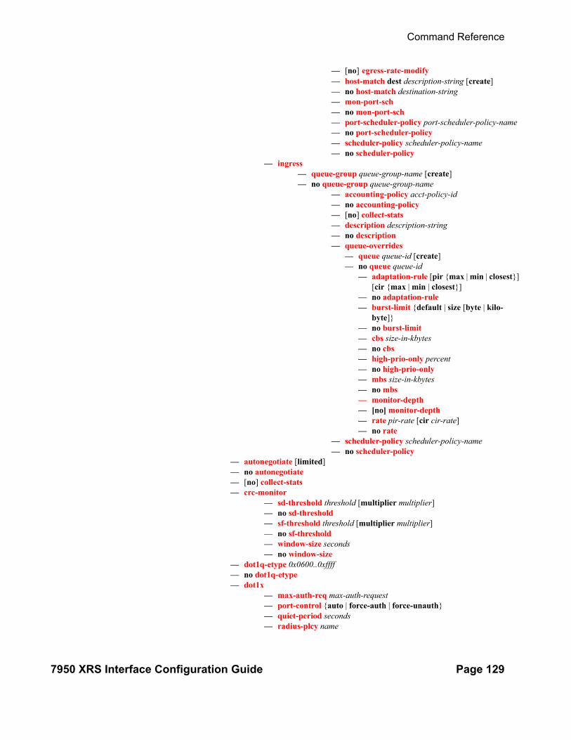
Command Reference
7950 XRS Interface Configuration Guide Page 129
— [no] egress-rate-modify— host-match dest description-string [create]— no host-match destination-string— mon-port-sch — no mon-port-sch — port-scheduler-policy port-scheduler-policy-name— no port-scheduler-policy— scheduler-policy scheduler-policy-name— no scheduler-policy
— ingress— queue-group queue-group-name [create] — no queue-group queue-group-name
— accounting-policy acct-policy-id— no accounting-policy— [no] collect-stats— description description-string— no description— queue-overrides
— queue queue-id [create]— no queue queue-id
— adaptation-rule [pir {max | min | closest}] [cir {max | min | closest}]
— no adaptation-rule— burst-limit {default | size [byte | kilo-
byte]}— no burst-limit— cbs size-in-kbytes— no cbs— high-prio-only percent— no high-prio-only— mbs size-in-kbytes— no mbs— monitor-depth— [no] monitor-depth— rate pir-rate [cir cir-rate]— no rate
— scheduler-policy scheduler-policy-name— no scheduler-policy
— autonegotiate [limited]— no autonegotiate— [no] collect-stats— crc-monitor
— sd-threshold threshold [multiplier multiplier]— no sd-threshold— sf-threshold threshold [multiplier multiplier]— no sf-threshold— window-size seconds— no window-size
— dot1q-etype 0x0600..0xffff— no dot1q-etype— dot1x
— max-auth-req max-auth-request— port-control {auto | force-auth | force-unauth}— quiet-period seconds— radius-plcy name
Interfaces
Page 130 7950 XRS Interface Configuration Guide
— no radius-plcy— re-auth-period seconds — no re-auth-period— [no] re-authentication — server-timeout seconds— no server-timeout — supplicant-timeout seconds— no supplicant-timeout — transmit-period seconds— no transmit-period — tunneling— no tunneling
— [no] down-on-internal-error— down-when-looped
— keep-alive timer— no keep-alive— retry-timeout timer— no retry-timeout— [no] shutdown— [no] use-broadcast-address
— duplex {full | half}— efm-oam
— [no] accept-remote-loopback— discovery
— advertise-capability— link-monitoring— [no] link-monitoring
— [no] grace-tx-enable— hold-time time-value— no hold-time— [no] ignore-efm-state— link-monitoring
— errored-frame— [no] event-notification— sd-threshold errored-frames— no sd-threshold— sf-threshold errored-frames— [no] shutdown— window deciseconds
— errored-frame-period— [no] event-notification— sd-threshold errored-frames— no sd-threshold— sf-threshold errored-frames— [no] shutdown— window packets
— errored-frame-seconds — [no] event-notification— sd-threshold errored-seconds— no sd-threshold— sf-threshold errored-seconds— [no] shutdown— window deciseconds
— errored-symbols— [no] event-notification

Command Reference
7950 XRS Interface Configuration Guide Page 131
— sd-threshold errored-symbols— no sd-threshold— sf-threshold errored-symbols— [no] shutdown— window deciseconds
— local-sf-action— event-notification-burst packets— info-notification
— [no] dying-gasp— [no] critical-event
— local-port-action {log-only | out-of-service}— [no] shutdown
— mode {active | passive}— peer-rdi-rx
— critical-event local-port-action {log-only | out-of-service}— dying-gasp local-port-action {log-only | out-of-service}— event-notification local-port-action {log-only | out-of-ser-
vice} — link-fault local-port-action {log-only |out-of-service}
— [no] shutdown— [no] transmit-interval interval [multiplier multiplier]— [no] tunneling
— egress— [no] exp-secondary-shaper
— rate {max | kilobits-per-second}— no rate— class class-number rate {kilobits-per-second | max} [moni-
tor-threshold size-in-kilobytes] — no class— low-burst-max-class class— no low-burst-max-class
— egress-rate sub-rate— no egress-rate— [no] egress-scheduler-override
— level priority-level rate pir-rate [cir cir-rate]— no level priority-level— max-rate rate— no max-rate
— egress-scheduler-policy port-scheduler-policy-name— no egress-scheduler-policy— elmi
— mode {none|uni-n}— n393 [2..10]— no n393— t391 [5..30]— no t391— t392 [5..30]— no t392
— encap-type— encap-type {dot1q | null | qinq}— no encap-type— eth-cfm
— [no] mep mep-id domain md-index association ma-index [vlan vlan-id]— [no] ais-enable
— client-meg-level [level [level ...]]
Interfaces
Page 132 7950 XRS Interface Configuration Guide
— no client-meg-level— interval {1|60}— no interval— priority priority-value— no priority
— [no] ccm-enable— ccm-ltm-priority priority— no ccm-ltm-priority— ccm-padding-size ccm-padding— no ccm-padding-size— ccm-tlv-ignore [port-status] [interface-status]— no ccm-tlv-ignore— collect-lmm-stats— no collect-lmm-stats— description description-string— no description— [no] eth-test-enable
— bit-error-threshold bit-errors— test-pattern {all-zeros|all-ones} [crc-enable]— no test-pattern
— [no] facility-fault— low-priority-defect {allDef|macRemErrXcon|remErrX-
con|errXcon|xcon|noXcon}— mac-address mac-address— no mac-address— one-way-delay-threshold seconds— [no] shutdown
— hold-time {[up hold-time up] [down hold-time down] [seconds| centiseconds]}— no hold-time— [no] hsmda-scheduler-overrides
— group group-id rate rate— no group group-id— max-rate rate— no max-rate— scheduling-class class rate rate— scheduling-class class weight weight-in-group— no scheduling-class class
— ingress-rate ingress-rate— no ingress-rate— [no] lacp-tunnel— lldp
— dest-mac {nearest-bridge | nearest-non-tpmr | nearest-customer}— admin-status {rx | tx | tx-rx | disabled}— [no] notification— portid-subtype {tx-if-alias | tx-if-name | tx-local}— [no] tunnel-nearest-bridge— tx-mgmt-address [system] [system-ipv6]— no tx-mgmt-address— tx-tlvs [port-desc] [sys-name] [sys-desc] [sys-cap]— no tx-tlvs
— load-balancing-algorithm option— no load-balancing-algorithm— mac ieee-address— no mac— mode {access | network | hybrid}

Command Reference
7950 XRS Interface Configuration Guide Page 133
— no mode— mtu mtu-bytes— no mtu— network
— accounting-policy policy-id— no accounting-policy— [no] collect-stats— egress
— queue-group queue-group-name [instance instance id] [cre-ate]
— no queue-group queue-group-name— accounting-policy acct-policy-id— no accounting-policy— agg-rate kilobits-per-second [queue-frame-based-
accounting]— no agg-rate
— rate {max | rate}— no rate
— [no] limit-unused-bandwidth— [no] collect-stats— description description-string— no description— host-match dest destination-string [create]— no host-match dest destination-string— queue-overrides
— queue queue-id [create]— no queue queue-id
— adaptation-rule [pir {max | min | closest}] [cir {max | min | closest}]
— no adaptation-rule— burst-limit— [no] burst-limit— cbs size-in-kbytes— no cbs— high-prio-only percent— no high-prio-only— mbs size-in-kbytes— no mbs— [no] monitor-depth— rate pir-rate [cir cir-rate]— no rate
— scheduler-policy scheduler-policy-name— no scheduler-policy— policer-control-policy policy-name
— queue-policy name— no queue-policy
— pbb-etype [0x0600..0xffff]— no pbb-etype— qinq-etype 0x0600..0xffff— no qinq-etype— [no] report-alarm [signal-fail] [remote] [local] [no-frame-lock]— [no] sflow— [no] single-fiber— speed {10 | 100 | 1000}— ssm

Interfaces
Page 134 7950 XRS Interface Configuration Guide
— [no] shutdown— code-type {sonet | sdh}— no code-type— [no] tx-dus
— symbol-monitor— sd-threshold threshold [multiplier multiplier]— no sd-threshold— sf-threshold threshold [multiplier multiplier]— no sf-threshold— [no] shutdown— window-size seconds— no window-size
— xgig {lan | wan}
Interface Group Handler Commands
config— [no] interface-group-handler group-id
— [no] member portid— threshold min— no threshold

Command Reference
7950 XRS Interface Configuration Guide Page 135
Multilink Bundle Commands
config— [no] port {bundle-id}
— multilink-bundle— fragment-threshold fragment-threshold— fragment-threshold unlimited— no fragment-threshold— ima
— atm— cell-format cell-format— min-vp-vpi value
— link-delay {activate | deactivate} milli-seconds— no link-delay {activate | deactivate}— max-bandwidth number-links— no max-bandwidth— test-pattern-procedure
— [no] shutdown— test-link port-id— no test-link— test-pattern pattern— no test-pattern
— version IMA-version— no version
— [no] interleave-fragments— [no] member port-id— minimum-links minimum-links— no minimum-links— mlfr
— ack-timeout seconds— no ack-timeout— egress
— qos-profile profile-id — no qos-profile
— frame-relay— lmi-type {ansi | itu | none | rev1}— mode {dce | dte | bidir}— n391dte intervals— n392dce threshold— n392dte threshold— n393dce count— n393dte count— t391dte keepalive— t392dce keepalive
— hello-timeout seconds — no hello-timeout— [no] identifier bundle-id-string — ingress
— qos-profile profile-id — no qos-profile
— retry-limit integer— no retry-limit
— mlppp— egress
— qos-profile profile-id
Interfaces
Page 136 7950 XRS Interface Configuration Guide
— no qos-profile— endpoint-discriminator class {ip-address | global-mac-address} [dis-
criminator-id discriminator-id]— no endpoint-discriminator— ingress
— qos-profile profile-id— no qos-profile
— [no] magic-number— multiclass count— no multiclass— [no] stateless-aps-switchover
— mrru mrru— no mrru— [no] protect-bundle— red-differential-delay red-diff-delay [down]— no red-differential-delay— [no] short-sequence— [no] working-bundle— yellow-differential-delay yellow-diff-delay— no yellow-differential-delay

Command Reference
7950 XRS Interface Configuration Guide Page 137
SONET-SDH CommandsSONET/SDH Commands config
— [no] port {port-id}— sonet-sdh
— clock-source {loop-timed | node-timed}— framing {sonet | sdh}— group sonet-sdh-index payload {tu3 | vt2 | vt15}— hold-time hold-time {[up hold-time up] [down hold-time down]}— no hold-time— loopback {line | internal}— no loopback— [no] path [sonet-sdh-index]
— access— egress
— vport name [create]— no vport name
— agg-rate agg-rate— [no] agg-rate
— rate {max | rate}— no rate— [no] limit-unused-bandwidth— [no] queue-frame-based-accounting
— description description-string— no description— [no] egress-rate-modify— host-match dest description-string [create]— no host-match destination-string— port-scheduler-policy port-scheduler-policy-
name— no port-scheduler-policy
SONET Path ATM Commands — atm— cell-format cell-format— ilmi [vpi/vci]— no ilmi
— egress— traffic-desc traffic-desc-profile-id— no traffic-desc
— ingress— traffic-desc traffic-desc-profile-id— no traffic-desc
— keep-alive [poll-frequency seconds] [poll-count value] [test-frequency seconds]
— no keep-alive— protocol protocol-type— no protocol— [no] shutdown
— min-vp-vpi value— cisco-hdlc
— down-count down-count— no down-count— keepalive time-interval— no keepalive— up-count up-count— no up-count
SONET Path ATM Commands

Interfaces
Page 138 7950 XRS Interface Configuration Guide
— crc {16 | 32}— description description— no description— [no] egress-scheduler-override
— level priority-level rate pir-rate [cir cir-rate]— no level priority-level— max-rate rate— no max-rate
— egress-scheduler-policy port-scheduler-policy-name— no egress-scheduler-policy— encap-type {atm | bcp-null | bcp-dot1q | ipcp | ppp-auto | frame-relay
| wan-mirror | cisco-hdlc}{bcp-null | bcp-dot1q | ipcp | ppp-auto | frame-relay | wan-mirror}
— frame-relay— [no] frf-12
— egress— qos-profile profile-id— no qos-profile
— fragment-threshold threshold— no fragment-threshold
— lmi-type {ansi | itu | none | rev1}— mode {dce | dte | bidir}— n391dte intervals— no n391dte— n392dce threshold— no n392dce— n392dte threshold— no n392dte— n393dce count— no n393dce— n393dte count— no n393dte— t391dte keepalive— no t391dte— t392dce keepalive— no t392dce
— mac ieee-address— no mac— mode {access | network | hybrid}— mtu mtu— no mtu— network
— accounting-policy policy-id— no accounting-policy— [no] collect-stats— queue-policy name— no queue-policy
— payload {sts3 | tug3 | ds3 | e3 | vt2 | vt15 | ds1 | e1}— ppp
— keepalive time-interval [dropcount drop-count]— no keepalive
— [no] report-alarm [pais] [plop] [prdi] [pplm] [prei] [puneq] [plcd]— [no] scramble— [no] shutdown— signal-label value

Command Reference
7950 XRS Interface Configuration Guide Page 139
— no signal-label— trace-string [trace-string]— no trace-string
— [no] report-alarm [loc] [lais] [lrdi] [ss1f] [lb2er-sd] [lb2er-sf] [slof][slos] [lrei]— [no] reset-port-on-path-down— section-trace {increment-z0 | byte value | string string}— [no] single-fiber— speed {oc3 | oc12}— no speed— [no] suppress-lo-alarm— threshold {ber-sd | ber-sf} rate threshhold-rate— no threshold {ber-sd | ber-sf}— [no] tx-dus

Interfaces
Page 140 7950 XRS Interface Configuration Guide
TDM Commands
config — [no] port {port-id}
— tdm — buildout {long | short}
DS1 Commands — [no] ds1 ds1-id— bert {2e3 | 2e9 | 2e11 | 2e15 | 2e20 | 2e20q | 2e23 | ones | zeros | alter-
nating} duration duration— no bert— bit-error-insertion rate— no bit-error-insertion— [no] channel-group channel-group
— atm— cell-format cell-format— min-vp-vpi value
— cisco-hdlc— down-count down-count— no down-count— keepalive time-interval— no keepalive— up-count up-count— no up-count
— crc {16 | 32}— [no] description description-string— [no] egress-scheduler-override
— level priority-level rate pir-rate [cir cir-rate]— no level priority-level— max-rate rate— no max-rate
— egress-scheduler-policy port-scheduler-policy-name— [no] encap-type {atm | bcp-null | bcp-dot1q | ipcp | ppp-
auto | frame-relay | wan-mirror | cisco-hdlc | cem}— frame-relay
— [no] frf-12— egress
— qos-profile profile-id— no qos-profile
— fragment-threshold threshold— no fragment-threshold
— [no] identifier frf16-link-id-string— lmi-type {ansi | itu | none | rev1}— mode {dce | dte | bidir}— n391dte intervals— no n391dte— n392dce threshold— no n392dce— n392dte threshold— no n392dte— n393dce count— no n393dce— n393dte count— no n393dte

Command Reference
7950 XRS Interface Configuration Guide Page 141
— t391dte keepalive— no t391dte— t392dce keepalive— no t392dce
— idle-cycle-flag {flags | ones}— no idle-cycle-flag— idle-payload-fill {all-ones}— idle-payload-fill pattern pattern— no idle-payload-fill— idle-signal-fill {all-ones}— idle-signal-fill pattern pattern— no idle-signal-fill— load-balancing-algorithm option— no load-balancing-algorithm— mac ieee-address— no mac— [no] mode {access | network}— mtu mtu-bytes— no mtu— network
— accounting-policy policy-id— no accounting-policy— [no] collect-stats— queue-policy name— no queue-policy
— ppp— [no] ber-sf-link-down— compress {acfc [pfc] | pfc [acfc]}— no compress— keepalive time-period [dropcount drop count]— no keepalive
— [no] scramble— [no] shutdown— speed {56 | 64}— timeslots timeslots— no timeslots
— clock-source {loop-timed | node-timed | adaptive | differential}— framing (DS-1) {esf | sf | ds1-unframed}— insert-single-bit-error— [no] invert-data— loopback {line | internal | fdl-ansi | fdl-bellcore | payload-ansi |
inband-ansi | inband-bellcore}— no loopback— [no] remote-loop-respond— [no] report-alarm [ais] [los] [oof] [rai] [looped]— [no] shutdown— signal-mode {cas}— no signal-mode— threshold {ber-sd | ber-sf} rate {1 | 5 | 10 | 50 | 100}— no threshold {ber-sd | ber-sf}
— hold-time hold-time {[up hold-time up] [down hold-time down]}— no hold-time— lbo [0dB | -7.5dB | -15.0dB | -22.5dB]— length {133 | 266 | 399 | 533 | 655}
Interfaces
Page 142 7950 XRS Interface Configuration Guide
DS3 Commands
— [no] ds3 [sonet-sdh-index]— atm
— cell-format cell-format— mapping mapping— min-vp-vpi value
— bert {2e3 | 2e9 | 2e11 | 2e15 | 2e20 | 2e20q | 2e23 | ones | zeros | alter-nating} duration duration
— no bert— bit-error-insertion rate— no bit-error-insertion — channelized {ds1 | e1}— no channelized— cisco-hdlc
— down-count down-count— no down-count— keepalive time-interval— no keepalive— up-count up-count— no up-count
— clock-source {loop-timed | node-timed}— crc {16 | 32}— description description-string— no description— [no] egress-scheduler-override
— level priority-level rate pir-rate [cir cir-rate]— no level priority-level— max-rate rate— no max-rate
— egress-scheduler-policy port-scheduler-policy-name— no egress-scheduler-policy— encap-type {atm | bcp-null | bcp-dot1q | ipcp | ppp-auto | frame-relay
| wan-mirror | cisco-hdlc | cem}— [no] feac-loop-respond— frame-relay
— [no] frf-12— egress
— qos-profile profile-id— no qos-profile
— fragment-threshold threshold— no fragment-threshold
— lmi-type {ansi | itu | none | rev1}— mode {dce | dte | bidir}— n391dte intervals— no n391dte— n392dce threshold— no n392dce— n392dte threshold— no n392dte— n393dce count— no n393dce— n393dte count— no n393dte— t391dte keepalive
Command Reference
7950 XRS Interface Configuration Guide Page 143
— no t391dte— t392dce keepalive — no t392dce
— framing (DS3) {c-bit | m23}— idle-cycle-flag {flags | ones}— load-balancing-algorithm option— no load-balancing-algorithm— loopback {line | internal | remote}— no loopback— mac ieee-address— no mac— mdl {eic | lic | fic | unit | pfi | port | gen} mdl-string— no mdl [eic | lic | fic | unit | pfi | port | gen]— mdl-transmit {path | idle-signal | test-signal}— no mdl-transmit [path | idle-signal | test-signal]— mode {access | network}— mtu mtu-bytes— no mtu— network
— accounting-policy policy-id— no accounting-policy— [no] collect-stats— queue-policy name— no queue-policy
— ppp— keepalive time-period [dropcount drop-count]— no keepalive
— [no] report-alarm [ais] [los] [oof] [rai] [looped]— [no] scramble— [no] shutdown— subrate {digital-link | larscom} rate-step— no subrate
E1 Commands
— [no] e1 [e1-id]— bert {2e3 | 2e9 | 2e11 | 2e15 | 2e20 | 2e20q | 2e23 | ones | zeros | alter-
nating} duration duration— no bert— bit-error-insertion rate— no bit-error-insertion— [no] channel-group channel-group-id
— atm— cell-format cell-format— min-vp-vpi value
— cisco-hdlc— down-count down-count— no down-count— keepalive time-interval— no keepalive— up-count up-count— no up-count
— crc {16 | 32}— description description-string— no description— [no] egress-scheduler-override
Interfaces
Page 144 7950 XRS Interface Configuration Guide
— level priority-level rate pir-rate [cir cir-rate]— no level priority-level— max-rate rate— no max-rate
— egress-scheduler-policy port-scheduler-policy-name— [no] encap-type {atm | bcp-null | bcp-dot1q | ipcp | ppp-
auto | frame-relay | wan-mirror | cisco-hdlc | cem}— frame-relay
— [no] frf-12— egress
— qos-profile profile-id— no qos-profile
— fragment-threshold threshold— no fragment-threshold
— [no] identifier frf16-link-id-string— lmi-type {ansi | itu | none | rev1}— mode {dce | dte | bidir}— n391dte intervals— no n391dte— n392dce threshold— no n392dce— n392dte threshold— no n392dte— n393dce count— no n393dce— n393dte count— no n393dte— t391dte keepalive— no t391dte— t392dce keepalive— no t392dce
— idle-cycle-flag {flags | ones}— idle-payload-fill {all-ones}— idle-payload-fill pattern pattern— no idle-payload-fill— idle-signal-fill {all-ones}— idle-signal-fill pattern pattern— no idle-signal-fill— load-balancing-algorithm option— no load-balancing-algorithm— mac ieee-address— no mac— [no] mode {access | network}— mtu mtu-bytes— no mtu— network
— accounting-policy policy-id— no accounting-policy— [no] collect-stats— queue-policy name— no queue-policy
— ppp— [no] ber-sf-link-down— keepalive time-period [dropcount drop count]— no keepalive

Command Reference
7950 XRS Interface Configuration Guide Page 145
— [no] scramble— [no] shutdown— speed {56 | 64}— timeslots timeslots— no timeslots
— clock-source {loop-timed | node-timed | adaptive | differential}— framing (E-1) {no-crc-g704 | g704 | e1-unframed}— insert-single-bit-error— [no] invert-data— loopback {line | internal}— no loopback— [no] report-alarm [ais] [los] [oof] [rai] [looped]— [no] shutdown— signal-mode {cas}— no signal-mode {cas}— threshold {ber-sd | ber-sf} rate {1 | 5 | 10 | 50 | 100}— no threshold {ber-sd | ber-sf}
E3 Commands
— [no] e3 [sonet-sdh-index]— atm
— cell-format cell-format— min-vp-vpi value
— bert {2e3 | 2e9 | 2e11 | 2e15 | 2e20 | 2e20q | 2e23 | ones | zeros | alter-nating} duration duration
— no bert— bit-error-insertion rate— no bit-error-insertion— cisco-hdlc
— down-count down-count— no down-count— keepalive time-interval— no keepalive— up-count up-count— no up-count
— clock-source {loop-timed | node-timed}— crc {16 | 32}— description description-string— no description— [no] egress-scheduler-override
— level priority-level rate pir-rate [cir cir-rate]— no level priority-level— max-rate rate— no max-rate
— egress-scheduler-policy port-scheduler-policy-name— encap-type {atm | bcp-null | bcp-dot1q | ipcp | ppp-auto | frame-
relay | wan-mirror | cisco-hdlc | cem}— [no] feac-loop-respond— frame-relay
— [no] frf-12— egress
— qos-profile profile-id— no qos-profile
— fragment-threshold threshold— no fragment-threshold

Interfaces
Page 146 7950 XRS Interface Configuration Guide
— lmi-type {ansi | itu | none | rev1}— mode {dce | dte | bidir}— n391dte intervals— no n391dte— n392dce threshold— no n392dce— n392dte threshold— no n392dte— n393dce count— no n393dce— n393dte count— no n393dte— t391dte keepalive— no t391dte— t392dce keepalive— no t392dce
— framing (E-3) {g751 | g832}— idle-cycle-flag {flags | ones}— no idle-cycle-flag— load-balancing-algorithm option— no load-balancing-algorithm— loopback {line | internal | remote}— no loopback— mac ieee-address— no mac— mdl {eic | lic | fic | unit | pfi | port | gen} mdl-string— no mdl [eic | lic | fic | unit | pfi | port | gen]— mdl-transmit {path | idle-signal | test-signal}— no mdl-transmit [path | idle-signal | test-signal]— mode {access | network}— mtu mtu-bytes— no mtu— network
— accounting-policy policy-id— no accounting-policy— [no] collect-stats— queue-policy name— no queue-policy
— ppp— keepalive time-period [dropcount drop-count]— no keepalive
— [no] report-alarm [ais] [los] [oof] [rai] [looped]— [no] scramble— [no] shutdown

Command Reference
7950 XRS Interface Configuration Guide Page 147
LAG Commands
configLAG Commands — lag [lag-id]
— [no] lag [lag-id]— access
— adapt-qos {link | port-fair | distribute [include-egr-hash-cfg]}— [no] per-fp-egr-queuing— [no] per-fp-ing-queuing— [no] per-fp-sap-instance
— bfd— disable-soft-reset-extension— family {ipv4 | ipv6}
— [no] bfd-on-distributing-only— local-ip-address ip-address— no local-ip-address— max-admin-down-time [interval | infinite]— no max-admin-down-time— max-setup-time [interval | infinite]— no max-setup-time— multiplier multiplier— no multiplier— receive-interval interval— no receive-interval— remote-ip-address ip-address— no remote-ip-address— transmit-interval interval— no transmit-interval— shutdown— no shutdown
— description long-description-string— no description— [no] dynamic-cost— encap-type {dot1q | null | qinq}— no encap-type— eth-cfm
— [no] mep mep-id domain md-index association ma-index [vlan vlan-id]— [no] ais-enable
— client-meg-level [level [level ...]]— no client-meg-level— interval {1|60}— no interval— priority priority-value— no priority
— [no] ccm-enable— ccm-ltm-priority priority— no ccm-ltm-priority— ccm-padding-size ccm-padding— no ccm-padding-size— ccm-tlv-ignore [port-status] [interface-status]— no ccm-tlv-ignore— ccm-tlv-ignore [port-status] [interface-status]— no ccm-tlv-ignore— collect-lmm-stats— no collect-lmm-stats

Interfaces
Page 148 7950 XRS Interface Configuration Guide
— description description-string— no description— [no] eth-test-enable
— bit-error-threshold bit-errors— test-pattern {all-zeros|all-ones} [crc-enable]— no test-pattern
— [no] facility-fault— low-priority-defect {allDef|macRemErrXcon|remErrXcon|errX-
con|xcon|noXcon}— mac-address mac-address— no mac-address— one-way-delay-threshold seconds— [no] shutdown
— hold-time down hold-down-time— no hold-time— lacp [mode] [administrative-key admin-key] [system-id system-id][system-priority
priority]— lacp-mux-control {coupled | independent}— no lacp-mux-control— lacp-xmit-interval {slow | fast}— no lacp-xmit-interval— [no] lacp-xmit-stdby— link-map-profile lag-link-map-profile-id [create] — no link-map-profile lag-link-map-profile-id
— description description-string— no description— failure-mode [discard | per-link-hash]— no failure-mode— link port-id {primary|secondary}— no link
— mac ieee-address— no mac— mode {access | network| hybrid}— no mode— per-link-hash— per-link-hash weighted— per-link-hash weighted auto-rebalance— no per-link-hash— port port-id [port-id …up to 64 total] [priority priority] [sub-group sub-group-id]— no port port-id [port-id …up to 64 total] — port-threshold value [action {dynamic-cost | down}]— no port-threshold— port-type {standard | hsmda}— no port-type— port-weight-speed {1 | 10}— no port-weight-speed— selection-criteria {highest-count | highest-weight | best-port} [slave-to-partner] [sub-
group-hold-time hold-time]— no selection-criteria— [no] shutdown — standby-signalling {lacp | power-off}— no standby-signalling— weight-threshold value action [{dynamic-cost | down}]— no weight-threshold

Command Reference
7950 XRS Interface Configuration Guide Page 149
Ethernet Ring Commands
config— eth-ring ring-id— no eth-ring
— compatible-version value— description long-description-string— no description— guard-time time— revert-time time— ccm-hold-time {down down-timeout | up up-timeout}— [no] rpl-node {owner | nbr}— node-id mac— [no] sub-ring {virtual-link | non-virtual-link}
— [no] interconnect {ring-id ring-id | vpls}— [no] propagate-topology-change
— path {a | b} [ { port-id | lag-id } raps-tag qtag[.qtag] ]— description long-description-string— [no] rpl-end— eth-cfm
— [no] mep mep-id domain md-index association ma-index— [no] ccm-enable— [no] ccm-ltm-priority priority— [no] eth-test-enable— bit-error-threshold bit-errors— mac-address mac-address— one-way-delay-threshold time— [no] shutdown
— [no] shutdown— [no] shutdown

Interfaces
Page 150 7950 XRS Interface Configuration Guide
Ethernet Tunnel Commands
config— eth-tunnel tunnel-id— no eth-tunnel
— ccm-hold-time {down down-timeout | up up-timeout}— no ccm-hold-time— description long-description-string— no description— ethernet
— encap-type {dot1q|qinq}— no encap-type— [no] mac ieee-address
— hold-time— member down time— no member
— lag-emulation— access
— adapt-qos {distribute | link | port-fair}— no adapt-qos— [no] per-fp-ing-queuing
— path-threshold num-paths— nopath-threshold
— [no] path path-index— description description-string— no description— control-tag vlan-id— no control-tag— eth-cfm
— [no] mep mep-id domain md-index association ma-index— [no] ccm-enable— ccm-ltm-priority priority— no ccm-ltm-priority— [no] eth-test-enable
— test-pattern {all zeros | all-ones} [crc-enable]— no test-pattern
— low-priority-defect {allDef | macRemErrXcon | remErrX-con | errXcon | xcon | noXcon}
— mac-address mac-address— no mac-address— [no] control-mep— [no] shutdown
— member port-id— no member— precedence {primary | secondary}— no precedence— [no] shutdown
— protection-type {g8031-1to1 | loadsharing}— revert-time time— no revert-time— [no] shutdown

Command Reference
7950 XRS Interface Configuration Guide Page 151
Multi-Chassis Redundancy Commands
config— redundancy
— bgp-multi-homing— boot-timer seconds— no boot-timer— site-activation-timer seconds— no site-activation-timer— site-min-down-timer min-down-time— no site-min-down-timer
— multi-chassis— [no] peer ip-address
— authentication-key [authentication-key | hash-key] [hash | hash2]— no authentication-key— description description-string— no description— [no] mc-endpoint
— [no] bfd-enable— boot-timer interval— no boot-timer— hold-on-neighbor-failure multiplier— no hold-on-neighbor-failure— keep-alive-interval interval— no keep-alive-interval— [no] passive-mode— [no] shutdown— system-priority value— no system-priority
— [no] mc-lag— hold-on-neighbor-failure multiplier— no hold-on-neighbor-failure— keep-alive-interval interval— no keep-alive-interval— lag lag-id lacp-key admin-key system-id system-id [remote-
lag remote-lag-id] system-priority system-priority source-bmac-lsb use-lacp-key
— lag lag-id lacp-key admin-key system-id system-id [remote-lag remote-lag-id] system-priority system-priority source-bmac-lsb MAC-Lsb
— lag lag-id lacp-key admin-key system-id system-id [remote-lag remote-lag-id] system-priority system-priority
— lag lag-id [remote-lag remote-lag-id]— no lag lag-id— [no] shutdown
— mc-ring— ring sync-tag [create]— no ring sync-tag
— in-band-control-path— dst-ip ip-address— no dst-ip— interface ip-int-name— no interface— service-id service-id— no service-id

Interfaces
Page 152 7950 XRS Interface Configuration Guide
— [no] path-b— [no] range vlan-range
— [no] path-excl— [no] range vlan-range
— ring-node ring-node-name [create]— no ring-node ring-node-name
— connectivity-verify— dst-ip ip-address— no dst-ip— interval interval— no interval— service-id service-id— no service-id— [no] shutdown— src-ip ip-address— no src-ip— src-mac ieee-address— no src-mac— vlan [vlan-encap]— no vlan
— [no] shutdown— [no] shutdown— source-address ip-address— no source-address— [no] sync
— [no] igmp— [no] igmp-snooping— [no] mc-ring— [no] mld— [no] mld-snooping— port [port-id | lag-id] [sync-tag sync-tag]— no port [port-id | lag-id]
— range encap-range [sync-tag sync-tag]— no range encap-range
— [no] shutdown— [no] srrp— [no] sub-mgmt

Command Reference
7950 XRS Interface Configuration Guide Page 153
Show Commands
show — aps [port port-id] [group group-name] [detail]— chassis [environment] [power-supply]
— power-management [requirements | utilization] [detail]— card state— card [slot-number]— card [slot-number] detail— card slot-number fp [1..2] ingress queue-group mode {access|network}— card slot-number [detail] fp [1..2] ingress queue-group queue-group-name instance [1..65535]
mode {access|network} [statistics]— cflowd— elmi
— evc [port-id [vlan vlan-id]]— uni [port-id]
— eth-tunnel— interface-group-handler [igh-id]— mcm slot [/mcm] [detail]— mda slot [/mda] [detail]— pools mda-id[/port] [access-app [pool-name | service service-id | queue-group queue-group-name]]— pools mda-id[/port] [network-app [pool-name | queue-group queue-group-name]]— pools mda-id[/port] [direction [pool-name|service service-id | queue-group queue-group-name]]— lag [lag-id] [detail] [statistics]— lag [lag-id] description— lag [lag-id] port— lag lag-id associations— lag lag-id bfd— lag lag-id [detail] eth-cfm [tunnel tunnel-id]— lag lag-id associations per-link-hash interface [class {1 | 2 | 3}]— lag lag-id associations link-map-profile [link-map-profile] interface— lag lag-id lacp-partner— lag lag-id detail lacp-partner— lag lag-id link-map-profile link-map-profile— lag lag-id associations per-link-hash sap— lag lag-id associations link-map-profile [link-map-profile] sap— lag [lag-id] [detail] [statistics] [eth-cfm tunnel tunnel-id]— lag lag-id associations— lag lag-id per-link-hash [class {1 | 2 | 3}] [class {1 | 2 | 3}]— lag lag-id per-link-hash port port-id— megapools slot-number— megapools slot-number fp forwarding-plane [service-id service-id] [queue-group queue-group-
name] [ingress | egress]— multilink-bundle [bundle-id | bpgrp-id | slot/mda | type {mlppp | ima-grp | mlfr }][detail] — multilink-bundle [bundle-id | bpgrp-id | slot/mda] [ppp | ima | mlfr] — multilink-bundle [bundle-id | bpgrp-id] relations — multilink-bundle bundle-id mlfr [frame-relay [detail]]— multilink-bundle [bundle-id | bpgrp-id | slot/mda | type {mlppp | ima-grp}] [detail] — multilink-bundle [bundle-id | bpgrp-id | slot/mda | [ppp | ima]— multilink-bundle [bundle-id | bpgrp-id] relations
— ima— atm [detail]
— connections— port-connection [detail]— pvc [detail]

Interfaces
Page 154 7950 XRS Interface Configuration Guide
— pvp [vpi] [detail]— pvt [vpi.vci] [detail]
— ppp [multiclass]— relations
— peq [peq-slot] [detail]— port port-id [count] [detail] — port port-id description — port port-id associations— port port-id atm — port port-id atm connections— port port-id atm cp— port port-id atm ilmi— port port-id atm interface-connections— port port-id atm pvc [vpi[/vci]] [detail]— port port-id atm pvp [vpi] [detail]— port port-id atm pvt [vpi-range] [detail]— port port-id cisco-hdlc [detail]— port port-id mlfr-link[detail]— port port-id frame-relay [detail]— port port-id otu [detail]— port port-id ppp [detail]— port port-id queue-group [ingress|egress] [queue-group-name] [access|network] [{statistic|asso-
cations}]— port port-id queue-group qgrp-id [instance instance-id] queue-depth [queue queue-id]
[ingress|egress] [access|network]— port port-id dot1x [detail]— port port-id ethernet [[efm-oam [event-logs {failure|degraded} {active|cleared}] | detailed]
— dot1x [detail]— lldp [nearest-bridge | nearest-non-tpmr | nearest-customer] [remote-info] [detail]— port aps [detail]
— port cem— port port-id ima-link— port port-id ima-link— port port-id monitor-threshold— port port-id vport vport-name monitor-threshold— port-tree port-id— redundancy
— multi-chassis all— multi-chassis mc-lag— multi-chassis sync
— mc-lag peer ip-address [lag lag-id]— mc-lag [peer ip-address [lag lag-id]] statistics— mc-ring peer ip-address statistics— mc-ring peer ip-address [ring sync-tag [detail | statistics] ] — mc-ring peer ip-address ring sync-tag ring-node [ring-node-name [detail | sta-
tistics] ]— mc-ring global-statistics
— system— lldp [neighbor] neighbor— switch-fabric high-bandwidth-multicast

Command Reference
7950 XRS Interface Configuration Guide Page 155
Monitor Commands
For more information about monitor commands, refer to the OS Basic System Configuration Guide for command usage and CLI syntax.
For more information about monitor commands, refer to the 7450 ESS OS Basic System Configuration Guide for command usage and CLI syntax.
monitor— card slot-number fp fp-number ingress {access | network} queue-group queue-group-name instance
instance-id [absolute] [interval seconds] [repeat repeat] policer policer-id— port port-id [port-id...(up to 5 max)] [interval seconds] [repeat repeat] [absolute | rate] [multiclass]— queue-group queue-group-name egress access egress-queue egress-queue-id [interval seconds]
[repeat repeat] [absolute | rate] — queue-group queue-group-name ingress access ingress-queue ingress-queue-id [interval seconds]
[repeat repeat] [absolute | rate] — queue-group queue-group-name egress network instance instance-id [policer policer-id] [egress-
queue egress-queue-id] [interval seconds] [repeat repeat] [absolute | rate]— port atm [interval seconds] [repeat repeat] [absolute | rate]— port (ATM) atm [interval seconds] [repeat repeat] [absolute | rate]
Clear Commands
clear— card slot-number soft [hard-reset-unsupported-mdas]— card slot-number fp [1..2] ingress mode {access|network} queue-group group-name instance
instance statistics— card slot-number [soft]— lag lag-id statistics— mda mda-id [statistics]— port port-id statistics— port port-id statistics— port port-id atm pvc [vpi[/vci]] statistics— port port-id atm pvp [vpi] statistics— port port-id atm pvt [vpi1.vpi2] statistics— port port-id atm ilmi statistics— port port-id atm interface-connection statistics— port port-id statistics— port port-id atm pvc [vpi[/vci]] statistics— port port-id atm pvp [vpi] statistics— port port-id atm pvt [vpi1.vpi2] statistics— port port-id atm ilmi statistics— port port-id atm interface-connection statistics— port port-id ethernet efm-oam events local|remote— port port-id queue-group qgrp-id [instance instance-id] queue-depth [queue queue-id]
{ingress|egress} [access|network]— port port-id queue-group queue-group-name [access | network] {ingress | egress} [access|network]
[{statistics|associations}]— queue-group queue-group-name egress access egress-queue egress-queue-id [interval seconds]
[repeat repeat] [absolute | rate] — queue-group queue-group-name ingress access ingress-queue ingress-queue-id [interval seconds]
[repeat repeat] [absolute | rate]

Interfaces
Page 156 7950 XRS Interface Configuration Guide
— queue-group queue-group-name egress network instance instance-id [policer policer-id] [egress-queue egress-queue-id] [interval seconds] [repeat repeat] [absolute | rate]
Debug Commands
debug— atm— cisco-hdlc port-id— atm
— ilmi [port-id]— no ilmi port-id
— frame-relay— lmi [port-id]— [no] frf16 port-id
— cisco-hdlc port-id— lag [lag-id lag-id port port-id] [all]— lag [lag-id lag-id port port-id] [sm] [pkt] [cfg] [red] [iom-upd] [port-state] [timers] [sel-logic] [mc]
[mc-pkt]— no lag [lag-id lag-id]— [no] ppp port-id
Tools Commands
tools— dump
— aps aps-id [clear]— aps mc-aps-signaling [clear]— aps mc-aps-ppp [clear]— eth-tunnel tunnel-index [clear]— frame-relay port-id— lag lag-id lag-id— map-to-phy-port {ccag ccag-id | lag lag-id | eth-tunnel tunnel-index} {isid isid [end-isid
isid] | service service-id | svc-name [end-service service-id | svc-name]} [summary]— lag port-id— redundancy
— multi-chassis— mc-ring— srrp-sync-data [instance instance-id] [peer ip-address]— sync-database [peer ip-address] [port port-id | lag-id] [sync-tag sync-
tag] [application {dhcps | igmp| igmp-snooping | mc-ring | srrp | sub-mgmt | mld-snooping}] [detail] [type {alarm-deleted | local-deleted}]
tools— perform
— aps— clear aps-id {protect | working}— exercise aps-id {protect | working}— force aps-id {protect | working}— lockout aps-id— request aps-id {protect | working}
— eth-ring— clear ring-id

Command Reference
7950 XRS Interface Configuration Guide Page 157
— This command clears a physical port that is acting as the working circuit for this APS group. force ring-id path {a | b}
— manual ring-id path {a | b}— ima
— reset bundle-id— lag
— clear-force all-mc— clear-force lag-id lag-id [sub-group sub-group-id]— clear-force peer-mc ip-address— force all-mc {active|standby}— force lag-id lag-id [sub-group sub-group-id] {active|standby}— force peer-mc peer-ip-address {active|standby}— load-balance lag-id lag-id [class {1|2|3}]

Interfaces
Page 158 7950 XRS Interface Configuration Guide
Interface Configuration
7950 XRS Interface Configuration Guide Page 159
Configuration Commands
• Generic Commands on page 159
• Card Commands on page 161
• MDA (XMA) Commands on page 169
• MDA/Port QoS Commands on page 173
• General Port Commands on page 179
• Ethernet Port Commands on page 190
• 802.1x Port Commands on page 234
• LLDP Port Commands on page 239
• Network Port Commands on page 241
• Interface Group Handler Commands on page 243
• SONET/SDH Port Commands on page 245
• SONET/SDH Path Commands on page 249
• LAG Commands on page 252
• Multi-Chassis Redundancy Commands on page 274
Generic Commands
description
Syntax description description-stringno description
Context config>portconfig>port>ethernet>access>egr>vportconfig>port>ethernet>access>egr>qgrpconfig>port>ethernet>access>ing>qgrpconfig>port>ethernet>network>egr>qgrpconfig>port>sonet-sdh>pathconfig>lagconfig>lag>link>map>profileconfig>port>ethernet>eth-cfm>mepconfig>card>fp>ingress>access>queue-groupconfig>card>fp>ingress>network>queue-group
Description This command creates a text description for a configuration context to help identify the content in the con-figuration file.
The no form of this command removes any description string from the context.

Interfaces
Page 160 7950 XRS Interface Configuration Guide
Default No description is associated with the configuration context.
Parameters long-description-string — The description character string. Strings can be up to 160 characters long com-posed of printable, 7-bit ASCII characters. If the string contains special characters (#, $, spaces, etc.), the entire string must be enclosed within double quotes.
shutdown
Syntax [no] shutdown
Context config>cardconfig>card>mdaconfig>interface-group-handlerconfig>portconfig>port>ethernetconfig>port>sonet-sdh>pathconfig>lagconfig>port>ethernet>eth-cfm>mepconfig>port>ethernet>efm-oamconfig>redundancy>multi-chassis>peerconfig>redundancy>mc>peer>mcrconfig>redundancy>mc>peer>mc-lagconfig>redundancy>mc>peer>mcr>ringconfig>redundancy>mc>peer>mcr>node>cvconfig>redundancy>multi-chassis>peer>sync
Description This command administratively disables an entity. When disabled, an entity does not change, reset, or remove any configuration settings or statistics.
The operational state of the entity is disabled as well as the operational state of any entities contained within.
The no form of this command administratively enables an entity.
Special Cases
card — The default state for a card is no shutdown.
interface group handler (IGH) — The default state for an IGH is shutdown.
mda — The default state for a mda is no shutdown.
lag — The default state for a Link Aggregation Group (LAG) is shutdown.
port — The default state for a port is shutdown.
path — The default state for a SONET/SDH path is shutdown.
Interface Configuration
7950 XRS Interface Configuration Guide Page 161
Card Commands
card
Syntax card slot-number no card slot-number
Context config
Description This mandatory command enables access to theXCM (card) and XMA (mda) CLI contexts.
The no form of this command removes the card from the configuration. All associated ports, services, and MDAs must be shutdown.
Default No cards are configured.
Parameters slot-number — The slot number of the card in the chassis.
Values 1 — 20
card-type
Syntax card-type card-typeno card-type
Context config>card
Description This mandatory command adds an XCM to the device configuration for the slot. The card type can be pre-provisioned, meaning that the card does not need to be installed in the chassis.
A card must be provisioned before an
A card can only be provisioned in a slot that is vacant, meaning no other card can be provisioned (config-ured) for that particular slot. To reconfigure a slot position, use the no form of this command to remove the current information.
A card can only be provisioned in a slot if the card type is allowed in the slot. An error message is generated if an attempt is made to provision a card type that is not allowed.
If a card is inserted that does not match the configured card type for the slot, then a medium severity alarm is raised. The alarm is cleared when the correct card type is installed or the configuration is modified.
A high severity alarm is raised if an administratively enabled card is removed from the chassis. The alarm is cleared when the correct card type is installed or the configuration is modified. A low severity trap is issued when a card is removed that is administratively disabled.
to An appropriate alarm is raised if a partial or complete card failure is detected. The alarm is cleared when the error condition ceases.
The no form of this command removes the card from the configuration.
Default No cards are preconfigured for any slots.

Interfaces
Page 162 7950 XRS Interface Configuration Guide
Parameters card-type — The type of card to be configured and installed in that slot.
Values xcm-x20
fail-on-error
Syntax [no] fail-on-error
Context config>card
Description This command controls the behavior of the card when any one of a specific set of card level errors is encoun-tered in the system. When the fail-on-error command is enabled, and any one (or more) of the specific errors is detected, then the Operational State of the card is set to Failed. This Failed state will persist until the clear card command is issued (reset) or the card is removed and re-inserted (re-seat). If the condition per-sists after re-seating the card, then Alcatel-Lucent support should be contacted for further investigation.
Enabling fail-on-error is only recommended when the network is designed to be able to route traffic around a failed card (redundant cards, nodes or other paths exist).
The list of specific errors includes:
• CHASSIS event ID# 2063 – tmnxEqCardPChipMemoryEvent
• CHASSIS event ID# 2076 – tmnxEqCardPChipCamEvent
• CHASSIS event ID# 2059 – tmnxEqCardPChipError (for ingress ethernet only)
• CHASSIS event ID# 2098 tmnxEqCardQChipBufMemoryEvent
• CHASSIS event ID# 2099 tmnxEqCardQChipStatsMemoryEvent
• CHASSIS event ID# 2101 tmnxEqCardQChipIntMemoryEvent
• CHASSIS event ID# 2102 tmnxEqCardChipIfDownEvent
• CHASSIS event ID# 2103 tmnxEqCardChipIfCellEvent
Note that upon the detection of the event/error in the system, the reporting of the event (logs) and the fail-on-error behavior of the card are independent. Log event control configuration will determine whether the events are reported in logs (or SNMP traps, etc) and the fail-on-error configuration will determine the behavior of the card. This implies that the card can be configured to fail-on-error even if the events are suppressed (some may be suppressed in the system by default). In order to facilitate post-failure analysis, it is recommended to enable the reporting of the specific events/errors (configure log event-control) when fail-on-error is enabled.
Default no fail-on-error
named-pool-mode
Syntax [no] named-pool-mode
Context config>card
Description This command places an IOM in the named pool mode. When in named pool mode, the system will change the way default pools are created and allow for the creation of MDA and port level named buffer pools.

Interface Configuration
7950 XRS Interface Configuration Guide Page 163
When not enabled, the system will create default ingress and egress pools per port. When enabled, the sys-tem will not create per port pools, instead a default network and access pool is created for ingress and egress and is shared by queues on all ports.
The named pool mode may be enabled and disabled at anytime. Care should be taken when changing the pool mode for an IOM as the process of changing to or from named pool mode causes an IOM reset if MDAs are currently provisioned on the slot. If MDAs have not been provisioned at the time the named-pool-mode or no named-pool-mode command is executed, the IOM is not reset (for example, when the sys-tem is booting, the named pool mode command does not reset the IOM since the mode is set prior to provi-sioning the IOM’s MDAs).
This command is not enabled for the ISA-AA MDA.
The no form of the command converts the pool mode on the IOM card to the default mode. If MDAs are currently provisioned on the IOM, the card is reset.
named-pool-mode
Syntax named-pool-mode
Context config>card>mdaconfig>port
Description The named-pool-mode CLI context is used to store the MDA and port level named pool mode configuration commands. Currently, only the ingress and egress named-pool-policy commands are supported. Any future named pool mode configuration commands or overrides will be placed in the named-pool-mode CLI con-text. Within the context is an ingress and egress context.
Enter the named-pool-mode to define the ingress and egress named pool policy associations for either an MDA or port. The node may be entered regardless of the current named-pool-mode state of the IOM.
power-priority-level
Syntax power-priority-level 1—200
Context config>card>mda
Description This command sets the power priority value. An operator must assign a priority value to each XMA using a range of number from 1 to 200. The lowest number has the highest priority. The default priority is 150. The priority number range from 1 – 100 should be used for modules considered essential for system operation. Lower priority values of 101 – 200 should be used for non-essential modules.

Interfaces
Page 164 7950 XRS Interface Configuration Guide
Power Commands
mode
Syntax mode [none|basic|advanced]
Context config>system>power-management
Description This command sets the power mode
Parameters none — Specifies that there is no management of power to modules. In this mode, no gradual shutdown of active XCMs and XMAs is enforced. No spare capacity is reserved and any APEQ failure may result in brownouts or card failures.
basic — Specifies that the node will bring up as many provisioned modules (in order of priority) as possible using the N+1 algorithm. In basic mode the system shuts down IO cards when power capacity drops below the Power Safety Level.
advanced — Specifies that the operator can maintain a spare APEQ as long as possible to make it immune to the possibility of power brown-outs. In advanced mode, the system starts shutting down IO cards when the power capacity drops below the Power Safety Level + Max rated APEQ.
Default basic mode
power-safety-level
Syntax power-safety-level %
Context config>system>power-management
Description This command sets the Power Safety Level, which is a percentage of the calculated worst case power draw value. It is set to 100% by default. Once a Power Safety Level is configured by the operator, both the Basic and Advanced modes use the Power Safety Level as a reference for calculating the power redundancy using N+1 algorithm during start up and recovery from power depression.
Parameters % — Specifies the Power Safety Level as a percentage of the calculated worst case power draw value.
power safety-alert
Syntax power safety-alert value in watts
Context config>system>power-management
Description This command sets a value in watts for the Power Safety Alert .The Power Safety Alert minor alarm is gen-erated when the system power capacity drops below the Power Safety Level (in watts) + the Power Safety Alert. This is a critical level, which when breached the system starts shutting down IO cards based on card priority.

Interface Configuration
7950 XRS Interface Configuration Guide Page 165
peq
Syntax peq peq-slot
Context config>system>power-management
Description This command sets the APEQ slot number.
Parameters peq-slot — An identifier the APEQ slot.
Values 1 — 12
peq-type
Syntax [no] peq-type peq-type
Context config>system>power-management>peq
Description This command sets the type of APEQ for the designated APEQ slot.
The no form of the command reverts to the default setting.
Parameters peq-type — An identifier the APEQ type.
Values apeq-dc-2000
Default apeq-dc-2000
shutdown
Syntax [no] shutdown
Context config>system>power-management>peq
Description This command administratively enables/disables the APEQ.

Interfaces
Page 166 7950 XRS Interface Configuration Guide
Virtual Scheduler Commands
rate-calc-min-int
Syntax rate-calc-min-int [fast-queue percent-of-default] [slow-queue percent-of-default]no rate-calc-min-int
Context config>card>virt-sched-adj
Description This command overrides the default minimum time that must elapse before a queue’s offered rate may be recalculated. A minimum time between offered rate calculations is enforced to both prevent inaccurate esti-mation of the offered rate and excessive input to the virtual scheduler process.
In order to smooth out rapidly fluctuating offered rates, the system averages the measured offered rate with a window of previously measured offered rates. The window size is based on 4x the minimum rate calculation interval. Any previous measured offered rates within the window are used in the averaging function.
The system separates queues into fast and slow categories and maintains a separate minimum recalc interval for each type. The default minimum recalculation times for each type are as follows:
Slow Queue
Minimum Rate Calculation Interval: 0.1875 Seconds
Averaging Window Size: 0.75 Seconds
Fast Queue
Minimum Rate Calculation Interval: 0.0625 Seconds
Averaging Window Size: 0.25 Seconds
The actual minimum rate calculation interval may be increased or decreased by using the fast-queue and/or slow-queue keywords followed by a percent value which is applied to the default interval. The default slow-queue threshold rate is 1Mbps. Once a queue is categorized as slow, its rate must rise to 1.5Mbps before being categorized as a fast queue. The categorization threshold may be modified by using the slow-queue-thresh command.
The no rate-calc-min-interval command is used to restore the default fast queue and slow queue minimum rate calculation interval.
Parameters fast-queue percent-of-default: — The fast-queue percent-of-default parameter is optional and is used to modify the default minimum rate calculation time for “fast” queues. Defining 100.00 percent is equiva-lent to removing the override (restoring the default) on the fast queue minimum rate calculation time.
Values 0.01% to 1000.00%
Default 100.00%
slow-queue percent-of-default: — The slow-queue percent-of-default parameter is optional and is used to modify the default minimum rate calculation time for “slow” queues. Defining 100.00 percent is equiv-alent to removing the override (restoring the default) on the slow queue minimum rate calculation time.
Values 0.01% to 1000.00%

Interface Configuration
7950 XRS Interface Configuration Guide Page 167
Default 100.00%
sched-run-min-int
Syntax sched-run-min-int percent-of-defaultno sched-run-min-int
Context config>card>virt-sched-adj
Description This command is used to override the default minimum time that must elapse before a virtual scheduler may redistribute bandwidth based on changes to the offered rates of member queues. A minimum run interval is enforced to allow a minimum amount of “batching” queue changes before reacting to the changed rates. This minimum interval is beneficial since the periodic function of determining queue offered rates is per-formed sequentially and the interval allows a number queues rates to be determined prior to determining the distribution of bandwidth to the queues.
The default minimum scheduler run interval is 0.5 seconds. The sched-run-min-int command uses a percent value to modify the default interval.
The no sched-run-min-int command is used to restore the default minimum scheduler run interval for all vir-tual schedulers on the card.
Parameters percent-of-default: — The percent-of-default parameter is required and is used to modify the default mini-mum scheduler run interval for all virtual schedulers on the card. Defining 100.00 percent is equivalent to removing the override (restoring the default) for the minimum scheduler run interval.
Values 0.01% to 1000.00%
Default 100.00%
task-scheduling-int
Syntax task-scheduling-int percent-of-defaultno task-scheduling-int
Context config>card>virt-sched-adj
Description This command is used to override the system default time between scheduling the hierarchical virtual sched-uling task. By default, the system “wakes” the virtual scheduler task every 50ms; this is equivalent to five 10ms timer ticks. The task-scheduling-int command uses a percent value parameter to modify the number of timer ticks.
While the system accepts a wide range of percent values, the result is rounded to the nearest 10ms tick value. The fastest wake interval is 10ms (1 timer tick).
The no scheduling-int command is used to restore the default task scheduling interval of the card’s hierarchi-cal virtual scheduler task.

Interfaces
Page 168 7950 XRS Interface Configuration Guide
Parameters percent-of-default: — The percent-of-default parameter is required and is used to modify the default task scheduling interval for the hierarchical virtual scheduling task on the card. Defining 100.00 percent is equiv-alent to removing the override.
Values 0.01% to 1000.00%
Default 100.00%
slow-queue-thresh
Syntax slow-queue-thresh kilobits-per-secondno slow-queue-thresh
Context config>card>virt-sched-adj
Description This command is used to override the system default rate threshold where queues are placed in the “slow” queue category. Slow rate queues use a different minimum rate calculation interval time than fast rate queues. The rate is determined based on the previous calculated offered rate for the queue.
The default slow queue rate is 1Mbps. The fast rate is derived by multiplying the slow rate by a factor of 1.5 resulting in a default fast rate of 1.5Mbps. The slow-queue-thresh command uses a “Kilobit-Per-Second” value to modify the default slow queue rate threshold and indirectly changes the fast queue rate threshold.
The no slow-queue-thresh command is used to restore the default slow queue and fast queue rate thresholds.
Parameters kilobit-per-second: — The kilobit-per-second parameter is required and is used to modify the default slow queue rate threshold. Defining a value of 0 forces all queues to be treated as fast rate. Defining a value of 1000 (1Mbps) returns the threshold to the default value and is equivalent to executing no slow-queue-thresh.
The fast queue rate threshold is derived by multiplying the new slow queue rate threshold by a factor of 1.5.
Values 0 to 1000000 kilobits per second
Default 1000 kilobits per second

Interface Configuration
7950 XRS Interface Configuration Guide Page 169
MDA (XMA) Commands
mda
Syntax mda mda-slotno mda mda-slot
Context config>card
Description This mandatory command enables access to a card’s MDA CLI context to configure XMAs.
Default No MDA slots are configured by default.
Parameters mda-slot — The MDA slot number to be configured. Slots are numbered 1 and 2. The top MDA slot is num-ber 1, and the bottom MDA slot is number 2.
Values 1, 2
mda-type
Syntax mda-type mda-typeno mda-type
Context config>card>mda
Description This mandatory command provisions a specific MDA (XMA) type to the device configuration for the slot. The MDA can be preprovisioned but an MDA must be provisioned before ports can be configured. Ports can be configured once the MDA is properly provisioned.
A maximum of two MDAs can be provisioned on an XMA. Only one MDA can be provisioned per MDA slot. To modify an MDA slot, shut down all port associations.
Note: XMAs are provisioned using MDA commands. A medium severity alarm is generated if an MDA is inserted that does not match the MDA type configured for the slot. This alarm is cleared when the correct MDA is inserted or the configuration is modified.
A high severity alarm is raised when an administratively enabled MDA is removed from the chassis. This alarm is cleared if the either the correct MDA type is inserted or the configuration is modified. A low sever-ity trap is issued if an MDA is removed that is administratively disabled.
An alarm is raised if partial or complete MDA failure is detected. The alarm is cleared when the error condi-tion ceases.
All parameters in the MDA context remain and if non-default values are required then their configuration remains as it is on all existing MDAs.
The no form of this command deletes the MDA from the configuration. The MDA must be administratively shut down before it can be deleted from the configuration.
Default No MDA types are configured for any slots by default.

Interfaces
Page 170 7950 XRS Interface Configuration Guide
Parameters mda-type — The type of MDA selected for the slot postion.
7950: cx20-10g-sfp, cx2-100g-cfp
7750 SR-c12/4: m60-10/100eth-tx, m8-oc3-sfp, m5-1gb-sfp, m2-oc48-sfp, m20-100eth-sfp, m20-1gb-tx, m4-atmoc12/3-sfp, m20-1gb-sfp, m5-1gb-sfp-b, m4-choc3-as-sfp, c8-10/100eth-tx, c1-1gb-sfp,c2-oc12/3-sfp-b, c8-chds1, c4-ds3, c2-oc12/3-sfp, c1-choc3-ces-sfp, m1-choc12-as-sfp, m12-chds3-as, m4-chds3-as, m4-choc3-ces-sfp, m10-1gb-xp-sfp, m20-1gb-xp-sfp, m20-1gb-xp-tx
Default
egress-xpl
Syntax egress-xpl
Context configure>card>mda
Description This command enables the context to configure egress-xpl settings used by the fail-on-error feature.
threshold
Syntax threshold threshold
Context configure>card>mda>egress-xpl
Description This command configures the Egress XPL Error Threshold value used by the fail-on-error feature.
Parameters threshold — Specifies an upper limit on the frequency of Egress XPL Errors that can occur on the MDA. When fail-on-error is enabled, if the MDA experiences more than threshold errors per minute for win-dow minutes, the MDA will be put in the failed state.
threshold cannot be changed while fail-on-error is enabled for this MDA.
Values 1 - 1000000
Default 1000
window
Syntax window window
Context configure>card>mda>egress-xpl
Description This command configures the Error Window value used by the fail-on-error feature.
Parameters window — Specifies the time (in minutes) that the MDA can experience frequent Egress XPL Errors. When fail-on-error is enabled, if more than threshold Egress XPL errors per minute occur on the MDA for

Interface Configuration
7950 XRS Interface Configuration Guide Page 171
<window> consecutive minutes, the MDA will be put in the failed state.
window cannot be changed while fail-on-error is enabled for this MDA.
Values 1 - 1440
Default 60
fail-on-error
Syntax [no] fail-on-error
Context configure>card>mda
Description This command enables the fail-on-error feature. If an MDA is experiencing too many Egress XPL Errors, this feature causes the MDA to fail. This can force an APS switchover or traffic re-route. The purpose of this feature is to avoid situations where traffic is forced to use a physical link that suffers from errors but is still technically operational.
The feature uses values configured in the config>card>mda>egress-xpl context. When this feature is enabled on a MDA, if window consecutive minutes pass in which the MDA experiences more than threshold Egress XPL Errors per minute, then the MDA will be put in the failed state.
The no form of this command disables the feature on the MDA.
hi-bw-mcast-src
Syntax hi-bw-mcast-src [alarm] [group group-id]no hi-bw-mcast-src
Context config>card>mda
Description This command designates the MDA as a high-bandwidth IP multicast source, expecting the ingress traffic to include high-bandwidth IP multicast traffic. When configured, the system attempts to allocate a dedicated multicast switch fabric plane (MSFP) to the MDA. If a group is specified, all MDAs in the group will share the same MSFP. If the alarm parameter is specified and the system cannot allocate a dedicated MSFP to the new group or MDA, the MDAs will be brought online and generate an event (SYSTEM: 2052 - mdaHiBw-MulticastAlarm). Similarly, if during normal operation there is a failure or removal of resources, an event will be generated if the system cannot maintain separation of MSFPs for the MDAs.
The no form of the command removes the high-bandwidth IP multicast source designation from the MDA.
Default no hi-bw-mcast-src
Parameters alarm — Enables event generation if the MDA is required to share an MSFP with another MDA that is in a different group. MDAs within the same group sharing an MSFP will not cause this alarm.
group group-id — Specifies the logical MSFP group for the MDA. MDAs configured with the same group-id will be placed on the same MSFP.
Values 0 — 32 (A value of 0 removes the MDA from the group.)

Interfaces
Page 172 7950 XRS Interface Configuration Guide
Default By default, “none” is used, and the system will attempt to assign a unique MSFP to the MDA.
egress
Syntax egress
Context config>card>mda
Description This command enables the context to configure egress MDA parameters.
ingress
Syntax ingress
Context config>card>mda
Description This command enables the context to configure ingress MDA parameters.
mcast-path-management
Syntax mcast-path-management
Context config>card>mda>ingress
Description This command enables the context to configure local MDA settings for ingress multicast path management.
sync-e
Syntax [no] sync-e
Context config>card>mda
Description This command enables synchronous Ethernet on the MDA. Then any port on the MDA can be used as a source port in the sync-if-timing configuration.
The no form of the command disables synchronous Ethernet on the MDA.
Interface Configuration
7950 XRS Interface Configuration Guide Page 173
MDA/Port QoS Commands
access
Syntax access
Context config>card>mdaconfig>port
Description This command enables the access context to configure egress and ingress pool policy parameters.
On the MDA level, access egress and ingress pools are only allocated on channelized MDAs.
network
Syntax network
Context config>card>mda config>port
Description This command enables the network context to configure egress and ingress pool policy parameters.
On the MDA level, network egress pools are only allocated on channelized MDAs.
egress
Syntax egress
Context config>port>accessconfig>card>mda>accessconfig>card>mda>networkconfig>port>network
Description This command enables the context to configure egress buffer pool parameters which define the percentage of the pool buffers that are used for CBS calculations and specify the slope policy that is configured in the config>qos>slope-policy context.
On the MDA level, network and access egress pools are only allocated on channelized MDAs.
ingress
Syntax ingress
Context config>card>mda>access

Interfaces
Page 174 7950 XRS Interface Configuration Guide
config>card>mda>networkconfig>port>access
Description This command enables the context to configure ingress buffer pool parameters which define the percentage of the pool buffers that are used for CBS calculations and specify the slope policy that is configured in the config>qos>slope-policy context.
On the MDA level, access ingress pools are only allocated on channelized MDAs.
ingress-xpl
Syntax ingress-xpl
Context config>card>mda
Description This command enables the context to configure ingress MDA XPL interface error parameters.
threshold
Syntax threshold threshold
Context configure>card>mda>ingress-xpl
Description This command configures the Ingress XPL Error Threshold value used by the fail-on-error feature.
Parameters threshold — Specifies an upper limit on the frequency of Ingress XPL Errors that can occur on the MDA. When fail-on-error is enabled, if the MDA experiences more than threshold errors per minute for win-dow minutes, the MDA will be put in the failed state.
threshold cannot be changed while fail-on-error is enabled for this MDA.
Values 1 - 1000000
Default 1000
window
Syntax window window
Context configure>card>mda>ingress-xpl
Description This command configures the Error Window value used by the fail-on-error feature.
Parameters window — Specifies the time (in minutes) that the MDA can experience frequent Ingress XPL Errors. When fail-on-error is enabled, if more than threshold Ingress XPL errors per minute occur on the MDA for <window> consecutive minutes, the MDA will be put in the failed state.
window cannot be changed while fail-on-error is enabled for this MDA.
Values 1 - 1440
Interface Configuration
7950 XRS Interface Configuration Guide Page 175
Default 60
pool
Syntax [no] pool [name]
Context config>card>mda>access>egressconfig>card>mda>access>ingressconfig>card>mda>network>egressconfig>port>access>egressconfig>port>access>ingressconfig>port>network>egressconfig>port>network>ingressconfig>port>access>uplink>egress
Description This command configures pool policies.
On the MDA level, access and network egress and access ingress pools are only allocated on channelized MDAs. On the MDA level, access and network egress and access ingress pools are only allocated on chan-nelized MDAs. Network ingress pools are allocated on the MDA level for non-channelized MDAs.
Default default
Parameters name — Specifies the pool name, a string up to 32 characters long composed of printable, 7-bit ASCII char-acters. If the string contains special characters (#, $, spaces, etc.), the entire string must be enclosed within double quotes.
resv-cbs
Syntax resv-cbs percent-or-default amber-alarm-action step percent max [1..100]resv-cbs percent-or-defaultno resv-cbs
Context config>port>access>egress>poolconfig>port>ethernet>networkconfig>card>mda>access>egressconfig>card>mda>access>ingressconfig>card>mda>network>egressconfig>card>mda>network>ingressconfig>port>access>egress>channel>poolconfig>port>access>ingress>poolconfig>port>network>egress>pool
Description This command defines the percentage or specifies the sum of the pool buffers that are used as a guideline for CBS calculations for access and network ingress and egress queues. Two actions are accomplished by this command.
Interfaces
Page 176 7950 XRS Interface Configuration Guide
• A reference point is established to compare the currently assigned (provisioned) total CBS with the amount the buffer pool considers to be reserved. Based on the percentage of the pool reserved that has been provisioned, the over provisioning factor can be calculated.
• The size of the shared portion of the buffer pool is indirectly established. The shared size is important to the calculation of the instantaneous-shared-buffer-utilization and the average-shared-buffer-utilization variables used in Random Early Detection (RED) per packet slope plotting.
It is important to note that this command does not actually set aside buffers within the buffer pool for CBS reservation. The CBS value per queue only determines the point at which enqueuing packets are subject to a RED slope. Oversubscription of CBS could result in a queue operating within its CBS size and still not able to enqueue a packet due to unavailable buffers. The resv-cbs parameter can be changed at any time.
If the total pool size is 10 MB and the resv-cbs set to 5, the ’reserved size’ is 500 KB.
The no form of this command restores the default value.
The no resv-cbs command will clear all the adaptive configurations. There cannot be any adaptive sizing enabled for default resv-cbs.
Default default (30%)
Parameters percent-or-default — Specifies the pool buffer size percentage.
Values 0 — 100, default
amber-alarm-action step percent — specifies the percentage step-size for the reserved CBS size of the pool. When using the default value, the adaptive CBS sizing is disabled. To enable adaptive CBS sizing, step percent must be set to non-default value along with the max parameter. When reserved CBS is default adaptive CBS sizing cannot be enabled. The reserved CBS (Committed Burst Size) defines the amount of buffer space within the pool that is not considered shared.
Values 1 — 100
Default 0
max [1..100] — Specifies the maximum percentage for the reserved CBS size of the pool. When using the default value, the adaptive CBS sizing is disabled. To enable adaptive CBS sizing, max value must be set to non-default value along with the step percent. When reserved CBS is default adaptive CBS sizing cannot be enabled. The reserved CBS (Committed Burst Size) defines the amount of buffer space within the pool that is not considered shared. Max reserved CBS must not be more than the reserved CBS.
Values 1 — 100
Default 0
amber-alarm-threshold
Syntax amber-alarm-threshold percentageno amber-alarm-threshold
Context config>card>mda>access>egress>poolconfig>card>mda>access>ingress>poolconfig>card>mda>network>egress>poolconfig>card>mda>network>ingress>pool

Interface Configuration
7950 XRS Interface Configuration Guide Page 177
config>port>access>egress>poolconfig>port>access>ingress>poolconfig>port>network>egress>pool
Description This command configures the threshold for the amber alarm on the over-subscription allowed.
Users can selectively enable amber or red alarm thresholds. But if both are enabled (non-zero) then the red alarm threshold must be greater than the amber alarm threshold.
The no form of the command reverts to the default value.
Default 0
Parameters percentage — Specifies the amber alarm threshold.
Values 1 — 1000
red-alarm-threshold
Syntax red-alarm-threshold percentageno red-alarm-threshold
Context config>card>mda>access>egress>poolconfig>card>mda>access>ingress>poolconfig>card>mda>network>egress>poolconfig>card>mda>network>ingress>poolconfig>port>access>egress>poolconfig>port>access>ingress>poolconfig>port>network>egress>pool
Description This command configures the threshold for the red alarm on the over-subscription allowed.
Users can selectively enable amber or red alarm thresholds. But if both are enabled (non-zero) then the red alarm threshold must be greater than the amber alarm threshold.
The no form of the command reverts to the default value.
Default 0
Parameters percentage — Specifies the amber alarm threshold.
Values 1 — 1000
slope-policy
Syntax slope-policy nameno slope-policy
Context config>port>access>egress>poolconfig>card>mda>access>egressconfig>card>mda>access>ingressconfig>card>mda>network>egress

Interfaces
Page 178 7950 XRS Interface Configuration Guide
config>card>mda>network>ingressconfig>port>access>egress>channel>poolconfig>port>access>ingress>poolconfig>port>network>egress>pool
Description This command specifies an existing slope policy which defines high and low priority RED slope parameters and the time average factor. The policy is defined in the config>qos>slope-policy context.

Interface Configuration
7950 XRS Interface Configuration Guide Page 179
General Port Commands
port
Syntax port {port-id}no port port-id
Context config
Description This command enables access to the context to configure ports. Before a port can be configured, the chassis slot must be provisioned with a valid card type and the MDA parameter must be provisioned with a valid MDA type. (See card and mda commands.)
Default No ports are configured. All ports must be explicitly configured and enabled.
Parameters port-id — Specifies the physical port ID in the slot/mda/port format.
ddm-events
Syntax [no] ddm-events
Context config>port
Description This command enables Digital Diagnostic Monitoring (DDM) events for the port.
The no form of the command disables DDM events.
amplifier
Syntax amplifier
Context config>port>dwdm
Description This command enables you to tune the optical amplifier parameters.

Interfaces
Page 180 7950 XRS Interface Configuration Guide
queue-group
Syntax queue-group queue-group-name instance instance-idno queue-group
Context config>port>ethernet>network>egress
Description This command is used to create a queue-group instance in the network egress context of a port.
Queue-groups containing queues only or policers and queues can be instantiated. When a port is a LAG, one instance of the queue-group is instantiated on each member link.
One or more instances of the same queue-group name and/or a different queue-group name can be created in the network egress context of a port.
The queue-group-name must be unique within all network egress and access egress queue groups in the sys-tem. The queue-group instance-id must be unique within the context of the port.
The no version of this command deletes the queue-group instance from the network egress context of the port.
Parameters queue-group-name — Specifies the name of the queue group template up to 32 characters in length.
instance instance-id — Specifies the identication of a specific instance of the queue-group.
Values 1—40960
xgig
Syntax xgig {lan |wan}
Context config>port>ethernet
Description This command configures a 10 Gbps interface to be in Local or Wide Area Network (LAN or WAN) mode. When configuring the port to be in WAN mode, you can change certain SONET/SDH parameters to reflect the SONET/SDH requirements for this port. When you configure a port for LAN mode, all SONET/SDH parameters are pre-determined and not configurable.
Default lan
Parameters lan — Sets the port to operate in LAN mode.
wan — Sets the port to operate in WAN mode.
hybrid-buffer-allocation
Syntax hybrid-buffer-allocation
Context config>port
Description This command enables the context for configuring hybrid port buffer allocation parameters.

Interface Configuration
7950 XRS Interface Configuration Guide Page 181
ing-weight
Syntax ing-weight access access-weight network network-weightno ing-weight
Context config>port>hybrid-buffer-allocation
Description This command configures the sharing of the ingress buffers allocated to a hybrid port among the access and network contexts. By default, it is split equally between network and access.
The no form of this command restores the default values for the ingress access and network weights.
Parameters access-weight — Specifies the access weight as an integer.
Values 0 to 100
Default 50
network-weight — Specifies the network weight as an integer.
Values 0 to 100
Default 50
egr-weight
Syntax egr-weight access access-weight network network-weightno egr-weight
Context config>port>hybrid-buffer-allocation
Description This command configures the sharing of the egress buffers allocated to a hybrid port among the access and network contexts. By default, it is split equally between network and access.
The no form of this command restores the default values for the egress access and network weights.
Parameters access-weight — Specifies the access weight as an integer.
Values 0 to 100
Default 50
network-weight — Specifies the network weight as an integer.
Values 0 to 100
Default 50
modify-buffer-allocation-rate
Syntax modify-buffer-allocation-rate
Context config>port

Interfaces
Page 182 7950 XRS Interface Configuration Guide
Description This command enables the context to configure ingress and egress percentage of rate parameters. This com-mand only applies to physical ports (for example, it will not work on APS or similar logical ports). The per-centage of rate commands are used to define a percentage value that affects the amount of buffers used by ingress and egress port managed buffer space. Enter the modify-buffer-allocation-rate context when editing the port’s percentage of rate commands.
ing-percentage-of-rate
Syntax ing-percentage-of-rate rate-percentageno ing-percentage-of-rate
Context config>port>modify-buffer-allocation-rate
Description This command increases or decreases the active bandwidth associated with the ingress port that affects the amount of ingress buffer space managed by the port. Changing a port’s active bandwidth using the ing-per-centage-of-rate command is an effective means of artificially lowering the buffers managed by one ingress port and giving them to other ingress ports on the same MDA.
The ing-percentage-of-rate command accepts a percentage value that increases or decreases the active band-width based on the defined percentage. A value of 50% causes the active bandwidth to be reduced by 50%. A value of 150% causes the active bandwidth to be increased by 50%. Values from 1 to 1000 percent are supported.
A value of 100 (the default value) is equivalent to executing the no ing-percentage-of-rate command and restores the ingress active rate to the normal value.
Parameters rate-percentage — The rate-percentage parameter is required and defines the percentage value used to mod-ify the current ingress active bandwidth of the port. This does not actually change the bandwidth avail-able on the port in any way. The defined rate-percentage is multiplied by the ingress active bandwidth of the port. A value of 150 results in an increase of 50% (1.5 x Rate).
Values 1 — 1000
Default 100 (no change to active rate)
The no ing-percentage-of-rate command is used to remove any artificial increase or decrease of the ingress active bandwidth used for ingress buffer space allocation to the port. The no ing-percentage-of-rate com-mand sets rate-percentage to 100%.
egr-percentage-of-rate
Syntax egr-percentage-of-rate rate-percentageno egr-percentage-of-rate
Context config>port>modify-buffer-allocation-rate
Description The egr-percentage-of-rate command is used to increase or decrease the active bandwidth associated with the egress port that affects the amount of egress buffer space managed by the port. Changing a ports active bandwidth using the egr-percentage-of-rate command is an effective means of artificially lowering the buf-fers managed by one egress port and giving them to other egress ports on the same MDA.

Interface Configuration
7950 XRS Interface Configuration Guide Page 183
The egr-percentage-of-rate command accepts a percentage value that increases or decreases the active band-width based on the defined percentage. A value of 50% causes the active bandwidth to be reduced by 50%. A value of 150% causes the active bandwidth to be increased by 50%. Values from 1 to 1000 percent are supported.
A value of 100 (the default value) is equivalent to executing the no egr-percentage-of-rate command and restores the egress active rate to the normal value.
Parameters rate-percentage — The rate-percentage parameter is required and defines the percentage value used to mod-ify the current egress active bandwidth of the port. This does not actually change the bandwidth avail-able on the port in any way. The defined rate-percentage is multiplied by the egress active bandwidth of the port. A value of 150 results in an increase of 50% (1.5 x Rate).
Values 1 to 1000
Default 100 (no change to active rate)
The no egr-percentage-of-rate command is used to remove any artificial increase or decrease of the egress active bandwidth used for egress buffer space allocation to the port. The no egr-percentage-of-rate command sets rate-percentage to 100%.
egress-scheduler-override
Syntax [no] egress-scheduler-override
Context config>port>sonet-sdh>pathconfig>port>ethernet
Description This command applies egress scheduler overrides. When a port scheduler is associated with an egress port, it is possible to override the following parameters:
• The max-rate allowed for the scheduler.
• The maximum rate for each priority level 8 through 1.
• The CIR associated with each priority level 8 through 1.
See the 7750 SR OS Quality of Service Guide for command syntax and usage for the port-scheduler-policy command.
The no form of this command removes all override parameters from the egress port or channel scheduler context. Once removed, the port scheduler reverts all rate parameters back to the parameters defined on the port-scheduler-policy associated with the port.
level
Syntax level priority-level rate pir-rate [cir cir-rate]no level priority-level
Context config>port>ethernet>egress-scheduler-override
Description This command overrides the maximum and CIR rate parameters for a specific priority level on the port or channel’s port scheduler instance. When the level command is executed for a priority level, the correspond-

Interfaces
Page 184 7950 XRS Interface Configuration Guide
ing priority level command in the port-scheduler-policy associated with the port is ignored. The override level command supports the keyword max for the rate and cir parameter. When executing the level override command, at least the rate or cir keywords and associated parameters must be specified for the command to succeed.
The no form of this command removes the local port priority level rate overrides. Once removed, the port priority level will use the port scheduler policies level command for that priority level.
Parameters priority-level — Identifies which of the eight port priority levels are being overridden.
Values 1 — 8
rate pir-rate — Overrides the port scheduler policy’s maximum level rate and requires either the max key-word or a rate defined in kilobits-per-second to follow.
Values 1 — 40000000, max
cir cir-rate — Overrides the port scheduler policy’s within-cir level rate and requires either the max key-word or a rate defined in kilobits-per-second to follow.
Values 0— 40000000, max
max — removes any existing rate limit imposed by the port scheduler policy for the priority level allowing it to use as much total bandwidth as possible.
max-rate
Syntax max-rate rateno max-rate
Context configure>port>ethernet>egress-scheduler-override>level>rateconfigure>port>ethernet>egress-scheduler-override
Description This command overrides the max-rate parameter found in the port-scheduler-policy associated with the port. When a max-rate is defined at the port or channel level, the port scheduler policies max-rate parameter is ignored.
The egress-scheduler-override max-rate command supports a parameter that allows the override command to restore the default of not having a rate limit on the port scheduler. This is helpful when the port scheduler policy has an explicit maximum rate defined and it is desirable to remove this limit at the port instance.
The no form of this command removes the maximum rate override from the egress port or channels port scheduler context. Once removed, the max-rate parameter from the port scheduler policy associated with the port or channel will be used by the local scheduler context.
Parameters rate — Specifies the explicit maximum frame based bandwidth limit. This value overrides the QoS sched-uler policy rate.
Values 1 — 40000000, max
egress-scheduler-policy
Syntax egress-scheduler-policy port-scheduler-policy-name
Interface Configuration
7950 XRS Interface Configuration Guide Page 185
no egress-scheduler-policy
Context config>port>ethernet
Description This command enables the provisioning of an existing port-scheduler-policy to a port or channel.
The egress-scheduler-override node allows for the definition of the scheduler overrides for a specific port or channel.
When a port scheduler is active on a port or channel, all queues and intermediate service schedulers on the port are subject to receiving bandwidth from the scheduler. Any queues or schedulers with port-parent asso-ciations are mapped to the appropriate port priority levels based on the port-parent command parameters. Any queues or schedulers that do not have a port-parent or valid intermediate scheduler parent defined are treated as orphaned and are handled based on the port scheduler policies default or explicit orphan behavior.
The port scheduler maximum rate and priority level rate parameters may be overridden to allow unique val-ues separate from the port-scheduler-policy-name attached to the port or channel. Use the egress-scheduler-override command to specify the port or channel specific scheduling parameters.
The no form of this command removes a port scheduler policy from an egress port or channel. Once the scheduler policy is removed, all orphaned queues and schedulers revert to a free running state governed only by the local queue or scheduler parameters. This includes any queues or schedulers with a port-parent asso-ciation.
Parameters port-scheduler-policy-name — Specifies an existing port-scheduler-policy configured in the config>qos context.
elmi
Syntax elmi
Context config>port>ethernet
Description This command configures Ethernet Local Management Interface (E-LMI)parameters for the Ethernet port. E-LMI is only supported on Ethernet access ports with Dot1q encapsulation type.
mode
Syntax mode {none | uni-n}
Context config>port>ethernet>elmi
Description This command configures the the Ethernet LMI mode.
Default none
Parameters none — Specifies that theE LMI mode is set to none.
uni-n — Specifies that theE LMI mode is set to uni-n.

Interfaces
Page 186 7950 XRS Interface Configuration Guide
n393
Syntax n393 [2..10]no n393
Context config>port>ethernet>elmi
Description This command configures the monitored count of consecutive errors.
Parameters 2 .. 10 — Specifies the monitored count of consecutive errors.
t391
Syntax t391 [5..30]no t391
Context config>port>ethernet>elmi
Description This command configures the polling timer for UNI-C.
Parameters 5 ..30 — Specifies the polling timer for UNI-C.
t392
Syntax t392 [5..30]no t392
Context config>port>ethernet>elmi
Description This command configures the polling verification timer for UNI-N.
Parameters 5 .. 30 — Specifies the polling verification timer for UNI-N.
mode
Syntax mode {access | network | hybrid} no mode
Context config>port>ethernet
Description This command configures an Ethernet port for access, network or hybrid mode operation.
An access port or channel is used for customer facing traffic on which services are configured. A Service Access Point (SAP) can only be configured on an access port or channel. Once an Ethernet port has been configured for access mode, multiple services can be configured on the Ethernet port.
A network port or channel participates in the service provider transport or infrastructure network when a net-work mode is selected. When the network option is configured, the encap-type cannot be configured for the port/channel.
Interface Configuration
7950 XRS Interface Configuration Guide Page 187
A hybrid Ethernet port allows the combination of network and access modes of operation on a per-VLAN basis and must be configured as either dot1q or QinQ encapsulation.
When the hybrid port is configured to the dot1q encapsulation, the user configures a SAP inside a service simply by providing the SAP ID which must include the port-id value of the hybrid mode port and an unused VLAN tag value. The format is <port-id>:qtag1. A SAP of format <port-id>:* also supported.
The user configures a network IP interface under config>router>interface>port by providing the port name which consists of the port-id of the hybrid mode port and an unused VLAN tag value. The format is <port-id>:qtag1. The user must explicitly enter a valid value for qtag1. The <port-id>:* value is not sup-ported on a network IP interface. The 4096 VLAN tag space on the port is shared among VLAN SAPs and VLAN network IP interfaces.
When the hybrid port is configured to QinQ encapsulation, the user configures a SAP inside a service simply by providing the SAP ID which must include the port-id value of the hybrid mode port and the outer and inner VLAN tag values. The format is <port-id>:qtag1.qtag2. A SAP of format <port-id>: qtag1.* is also supported. The outer VLAN tag value must not have been used to create an IP network interface on this port. In addition, the qtag1.qtag2 value combination must not have been used by another SAP on this port.
The user configures a network IP interface under config>router>interface>port by providing the port name which consists of the port-id of the hybrid mode port and a VLAN tag value. The format is <port-id>:qtag1.*. An outer VLAN tag qtag2 of * is used to create an IP network interface. In addition, the qtag1.qtag2 value combination must not have been used on another SAP or IP network interface on this port.
The no form of this command restores the default.
Default network — Configures the Ethernet port for transport network use.
Parameters network — Configures the Ethernet port as service access.
access — Configures the Ethernet port for transport network use.
hybrid — Configures the Ethernet port for hybrid use.
per-link-hash
Syntax per-link-hash per-link-hash weightedper-link-hash weighted auto-rebalanceno per-link-hash
Context config>lag
Description This command configured per-link-hash on a LAG. When enabled SAPs/subscribers/interfaces are hashed on LAG egress to a single LAG link.
The no form of this command disables per-link-hash on a LAG.
Parameters weighted — SAPs/subscribers/interfaces are distributed amongst LAG links based on SAPs/subscribers/interfaces preconfigured class and weight. As new links are added to a LAG, existing SAPs subscribers are not impacted.
weighted auto-rebalance — SAPs/subscribers/interfaces are distributed amongst LAG links based on SAPs/subscribers/interfaces preconfigured class and weight. As new links are added to a LAG, existing

Interfaces
Page 188 7950 XRS Interface Configuration Guide
SAPs are rebalanced automatically.
mac
Syntax mac ieee-addressno mac
Context config>port>ethernetconfig>lag
Description This command assigns a specific MAC address to an Ethernet port, Link Aggregation Group (LAG).
Only one MAC address can be assigned to a port. When multiple mac commands are entered, the last com-mand overwrites the previous command. When the command is issued while the port is operational, IP will issue an ARP, if appropriate, and BPDU’s are sent with the new MAC address.
The no form of this command returns the MAC address to the default value.
Default A default MAC address is assigned by the system from the chassis MAC address pool.
Parameters ieee-address — Specifies the 48-bit MAC address in the form aa:bb:cc:dd:ee:ff or aa-bb-cc-dd-ee-ff where aa, bb, cc, dd, ee and ff are hexadecimal numbers. Allowed values are any non-broadcast, non-multicast MAC and non-IEEE reserved MAC addresses.
mtu
Syntax mtu mtu-bytesno mtu
Context config>port>ethernet
Description This command configures the maximum payload MTU size for an Ethernet port . The Ethernet port level MTU parameter indirectly defines the largest physical packet the port can transmit or the far-end Ethernet port can receive. Packets received larger than the MTU will be discarded. Packets that cannot be fragmented at egress and exceed the MTU are discarded.
The value specified for the MTU includes the destination MAC address, source MAC address, the Ethertype or Length field and the complete Ethernet payload. The MTU value does not include the preamble, start of frame delimiter or the trailing CRC.
The no form of this command restores the default values.
Default The default MTU value depends on the (sub-)port type, mode and encapsulation and are listed in the follow-ing table:
Type Mode Encap Type Default (Bytes)
10/100, Gig, or 10GigE Access null 1514

Interface Configuration
7950 XRS Interface Configuration Guide Page 189
Parameters mtu-bytes — Sets the maximum allowable size of the MTU, expressed as an integer.
Values 512 — 9212config>port>sonet-sdh>path512 — 9208
queue-policy
Syntax queue-policy nameno queue-policy
Context config>card>mda>network>ingress
Description This command specifies the network-queue policy which defines queue parameters such as CBS, high prior-ity only burst size, MBS, CIR and PIR rates, as well as forwarding-class to queue mappings. The network-queue policy is defined in the config>qos>network-queue context.
Default default
Parameters name — Specifies an existing network-queue policy name.
10/100, Gig, or 10GigE Access dot1q 1518
10/100, Gig, or 10GigE Access q-in-q 1522
SONET/SDH Network ppp-auto 1524
Type Mode Encap Type Default (Bytes)
Interfaces
Page 190 7950 XRS Interface Configuration Guide
Ethernet Port Commands
ethernet
Syntax ethernet
Context config>port
Description This command enables access to the context to configure Ethernet port attributes.
This context can only be used when configuring Fast Ethernet, gigabit, or 10Gig Ethernet LAN ports on an appropriate MDA.
mode
Syntax mode {access | network | hybrid}no mode
Context config>port>ethernet
Description This command configures an Ethernet port for access, network, or hybrid mode of operation.
An access port or channel is used for customer facing traffic on which services are configured. A Service Access Point (SAP) can only be configured on an access port or channel. When a port is configured for access mode, the appropriate encap-type must be specified to distinguish the services on the port. Once an Ethernet port, has been configured for access mode, multiple services can be configured on the Ethernet port
A network port or channel participates in the service provider transport or infrastructure network when a net-work mode is selected. When the network option is configured, the encap-type cannot be configured for the port/channel.
A hybrid Ethernet port allows the combination of network and access modes of operation on a per-VLAN basis and must be configured as either dot1q or QinQ encapsulation.
When the hybrid port is configured to the dot1q encapsulation, the user configures a SAP inside a service simply by providing the SAP ID which must include the port-id value of the hybrid mode port and an unused VLAN tag value. The format is <port-id>:qtag1. A SAP of format <port-id>:* also supported.
The user configures a network IP interface under config>router>interface>port by providing the port name which consists of the port-id of the hybrid mode port and an unused VLAN tag value. The format is <port-id>:qtag1. The user must explicitly enter a valid value for qtag1. The <port-id>:* value is not supported on a network IP interface. The 4096 VLAN tag space on the port is shared among VLAN SAPs and VLAN net-work IP interfaces.
When the hybrid port is configured to QinQ encapsulation, the user configures a SAP inside a service simply by providing the SAP ID which must include the port-id value of the hybrid mode port and the outer and inner VLAN tag values. The format is <port-id>:qtag1.qtag2. A SAP of format <port-id>: qtag1.* is also supported. The outer VLAN tag value must not have been used to create an IP network interface on this port. In addition, the qtag1.qtag2 value combination must not have been used by another SAP on this port.

Interface Configuration
7950 XRS Interface Configuration Guide Page 191
The user configures a network IP interface under config>router>interface>port by providing the port name which consists of the port-id of the hybrid mode port and a VLAN tag value. The format is <port-id>:qtag1.*. An outer VLAN tag qtag2 of * is used to create an IP network interface. In addition, the qtag1.qtag2 value combination must not have been used on another SAP or IP network interface on this port.
The no form of this command restores the default.
Default network — for Ethernet ports
Parameters access — Configures the Ethernet port as service access.
network — Configures the Ethernet port for transport network use.
hybrid — Configures the Ethernet port for hybrid use.
access
Syntax access
Context config>port>ethernet
Description This command configures Ethernet access port parameters.
egress
Syntax egress
Context config>port>ethernet>accessconfig>port>ethernet>network
Description This command configures Ethernet access egress port parameters.
queue-group
Syntax queue-group queue-group-name [instance instance-id] [create]no queue-group queue-group-name [instance instance-id]
Context config>port>ethernet>access>egressconfig>port>ethernet>access>ingress
Description This command creates an ingress or egress queue group on an Ethernet port. A queue group is a collection of queues identified by a group name. Queue groups created on access ports are used as an alternative queue destination for SAPs.
Within a SAP, a forwarding class may be redirected from the local SAP queue to a port queue group queue. The forwarding classes from multiple SAPs may be redirected to the same queue group which can be used to minimize the number of per-SAP queues.
Queue groups may be created on both access and network oriented ports. When the port is in access mode, the queue groups must be created within the port access node.

Interfaces
Page 192 7950 XRS Interface Configuration Guide
Within the access node, queue groups are also configured as ingress or egress. Access ingress queue groups can only be used by ingress SAP forwarding classes and only a single ingress queue group per port is sup-ported. Multiple access egress queue groups may be created on a single port and are used by egress SAP for-warding classes. The instance-id parameter identifies different instances of the same queue group template. Creating multiple queue groups with a different instance ID but the same queue group name results in sepa-rate queue groups being created on the port. The instance-id parameter is only valid for egress queue groups on access ports.
When the queue group is created in an ingress port context, the group-name must be an existing ingress queue group template. Similarly, queue groups created in an egress port context must have a group-name of an existing egress queue group template. Two ingress queue groups with the same name cannot be created on the same port. Two egress queue groups can only be created on the same port with the same queue group template name if they have different instance-id values.
The queues defined in the template are created on the queue group. The queue parameters within the tem-plate are used as the default queue parameters for each queue in the queue group. The default queue param-eters for each queue may be overridden on the queue group with specific queue parameters.
Each queue group supports the application of a scheduler-policy for the purpose of managing the queues within the group into an aggregate SLA. The queues defined within the template may be configured with parent scheduler defining the mapping of a queue to one of the schedulers within the scheduler policy. Egress queue groups also support the agg-rate parameter and the queues in the egress template support the port-parent command. Each command is used for configuring egress port virtual scheduling behavior.
Each queue group allows the application of an accounting policy and the ability to enable and disable col-lecting statistics. The statistics are derived from the queue counters on each queue within the queue group. The accounting policy defines which queue counters are collected and to which accounting file they will be written.
A queue group does not have an administrative shutdown or no shutdown command. A queue group is con-sidered to be always on once created.
When creating a queue group, the system will attempt to allocate queue resources based on the queues defined in the queue group template. If the appropriate queue resources do not currently exist, the queue group will not be created. Ingress port queue groups do not support the shared-queuing or multipoint-shared queuing behavior.
When the queue group is created on a LAG (Link Aggregation Group), it must be created on the primary port member. The primary port member is the port with the lowest port ID based on the slot, MDA position and port number on the MDA. A queue group created on the primary LAG port will be automatically created on all other port members. If a new port is being added to a LAG with an existing queue group, the queue group must first be created on the port prior to adding the port to the LAG. If the LAG queue group has queue overrides, the queue overrides must also be defined on the port queue group prior to adding the port to the LAG.
A port queue group cannot be removed from the port when a forwarding class is currently redirected to the group. All forwarding class redirections must first be removed prior to removing the queue group.
Default none
Parameters group-name — The group-name parameter is required when executing the port queue-group command. The specified group-name must exist as an ingress or egress queue group template depending on the ingress or egress context of the port queue group. Only a single queue group may be created on an ingress port. Multiple queue groups may be created on an egress port.

Interface Configuration
7950 XRS Interface Configuration Guide Page 193
instance-id — specifies the identification of a specific instance of the egress queue-group. This parameter is only valid for egress access port queue groups.
Values 1 — 40960
create — Keyword used to associate the queue group. The create keyword requirement can be enabled/ dis-abled in the environment>create context.
egress
Syntax egress
Context config>port>ethernet
This command configures Ethernet egress port parameters.
ingress
Syntax ingress
Context config>port>ethernet>access
Description This command configures Ethernet access ingress port parameters.
queue-group
Syntax queue-group queue-group-name [instance instance-id] [create] no queue-group queue-group-name
Context config>port>ethernet>access>egrconfig>port>ethernet>access>ing
Description This command creates an ingress or egress queue group on an Ethernet port. A queue group is a collection of queues identified by a group name. Queue groups created on access ports are used as an alternative queue destination for SAPs.
Within a SAP, a forwarding class may be redirected from the local SAP queue to a port queue group queue. The forwarding classes from multiple SAPs may be redirected to the same queue group which can be used to minimize the number of per-SAP queues.
Queue groups may be created on both access and network oriented ports. When the port is in access mode, the queue groups must be created within the port access node.
Within the access node, queue groups are also configured as ingress or egress. Access ingress queue groups can only be used by ingress SAP forwarding classes and only a single ingress queue group per port is sup-ported. Multiple access egress queue groups may be created on a single port and are used by egress SAP for-warding classes. The instance-id parameter identifies different instances of the same queue group template. Creating multiple queue groups with a different instance ID but the same queue group name results in sepa-

Interfaces
Page 194 7950 XRS Interface Configuration Guide
rate queue groups being created on the port. The instance-id parameter is only valid for egress queue groups on access ports.
When the queue group is created in an ingress port context, the group-name must be an existing ingress queue group template. Similarly, queue groups created in an egress port context must have a group-name of an existing egress queue group template. Two ingress queue groups with the same name cannot be created on the same port. Two egress queue groups can only be created on the same port with the same queue group template name if they have different instance-id values.
The queues defined in the template are created on the queue group. The queue parameters within the tem-plate are used as the default queue parameters for each queue in the queue group. The default queue param-eters for each queue may be overridden on the queue group with specific queue parameters.
Each queue group supports the application of a scheduler-policy for the purpose of managing the queues within the group into an aggregate SLA. The queues defined within the template may be configured with parent scheduler defining the mapping of a queue to one of the schedulers within the scheduler policy. Egress queue groups also support the agg-rate parameter and the queues in the egress template support the port-parent command. Each command is used for configuring egress port virtual scheduling behavior.
Each queue group allows the application of an accounting policy and the ability to enable and disable col-lecting statistics. The statistics are derived from the queue counters on each queue within the queue group. The accounting policy defines which queue counters are collected and to which accounting file they will be written.
A queue group does not have an administrative shutdown or no shutdown command. A queue group is con-sidered to be always on once created.
When creating a queue group, the system will attempt to allocate queue resources based on the queues defined in the queue group template. If the appropriate queue resources do not currently exist, the queue group will not be created. Ingress port queue groups do not support the shared-queuing or multipoint-shared queuing behavior.
When the queue group is created on a LAG (Link Aggregation Group), it must be created on the primary port member. The primary port member is the port with the lowest port ID based on the slot, MDA position and port number on the MDA. A queue group created on the primary LAG port will be automatically created on all other port members. If a new port is being added to a LAG with an existing queue group, the queue group must first be created on the port prior to adding the port to the LAG. If the LAG queue group has queue overrides, the queue overrides must also be defined on the port queue group prior to adding the port to the LAG.
A port queue group cannot be removed from the port when a forwarding class is currently redirected to the group. All forwarding class redirections must first be removed prior to removing the queue group.
Default none
Parameters group-name — The group-name parameter is required when executing the port queue-group command. The specified group-name must exist as an ingress or egress queue group template depending on the ingress or egress context of the port queue group. Only a single queue group may be created on an ingress port. Multiple queue groups may be created on an egress port.
instance-id — specifies the identification of a specific instance of the queue-group.
Values 1 — 40960
create — Keyword used to associate the queue group. The create keyword requirement can be enabled/disabled in the environment>create context.

Interface Configuration
7950 XRS Interface Configuration Guide Page 195
agg-rate
Syntax [no] agg-rate
Context config>port>ethernet>access>egr>qgrpconfig>port>ethernet>access>egr>vportconfig>port>ethernet>network>egr>qgrp
Description This command is used to control an HQoS aggregate rate limit. It is used in conjunction with the following parameter commands: rate, limit-unused-bandwidth, and queue-frame-based-accounting.
When specified under a VPORT, the agg-rate rate, port-scheduler-policy and scheduler-policy commands are mutually exclusive. Changing between the use of a scheduler policy and the use of an agg-rate/port-scheduler-policy involves removing the existing command and applying the new command.
rate
Syntax rate {max | rate}no rate
Context config>port>ethernet>access>egr>qgrp>agg-rateconfig>port>ethernet>access>egr>vport>agg-rateconfig>port>ethernet>network>egr>qgrp>agg-rate
Description This command defines the enforced aggregate rate for all queues associated with the agg-rate context. A rate must be specified for the agg-rate context to be considered to be active on the con-text’s object (SAP, subscriber, VPORT etc.).
Parameters rate — Specifies the rate limit for the VPORT.
Values max, 1— 800000000, max
limit-unused-bandwidth
Syntax [no] limit-unused-bandwidth
Context config>port>ethernet>access>egr>qgrp>agg-rateconfig>port>ethernet>access>egr>vport>agg-rateconfig>port>ethernet>network>egr>qgrp>agg-rateconfig>port>sonet-sdh>path>access>egress>vport
Description This command is used to enable (or disable) aggregate rate overrun protection on the agg-rate context.
queue-frame-based-accounting
Syntax [no] queue-frame-based-accounting
Context config>port>ethernet>access>egr>qgrp>agg-rate
Interfaces
Page 196 7950 XRS Interface Configuration Guide
config>port>ethernet>access>egr>vport>agg-rateconfig>port>ethernet>network>egr>qgrp>agg-rateconfig>port>sonet-sdh>path>access>egress>vport
Description This command is used to enabled (or disable) frame based accounting on all queues associated with the agg-rate context. Only supported on Ethernet ports. Not supported on HSMDA Ethernet ports.
host-match
Syntax host-match dest destination-string [create]no host-match dest destination-string
Context config>port>ethernet>access>egr>qgrp
Description This command configures host matching for the Ethernet port egress queue-group.
The no form of the command removes host matching for the Ethernet port egress queue-group.
Parameters dest destination-string — Specify a host match destination string up to 32 characters in length.
create — Keyword used to create the host match. The create keyword requirement can be enabled/disabled in the environment>create context.
queue-overrides
Syntax queue-overrides
Context config>port>ethernet>access>egr>qgrpconfig>port>ethernet>access>ing>qgrpconfig>port>ethernet>network>egr>qgrp
Description This command enables the context to define optional queue parameter overrides for each queue within the queue group.
queue
Syntax queue queue-id [queue-type] [create]no queue queue-id
Context config>port>ethernet>access>egr>qgrp>qoverconfig>port>ethernet>access>ing>qgrp>qoverconfig>port>eth>network>egr>qgrp>qover
Description This command associates a queue for use in a queue group template. The defined queue-id acts as a reposi-tory for the default parameters for the queue. The template queue is created on each queue-group object which is created with the queue group template name. Each queue is identified within the template by a queue-id number. The template ensures that all queue groups created with the template’s name will have the same queue-ids providing a uniform structure for the forwarding class redirection commands in the SAP

Interface Configuration
7950 XRS Interface Configuration Guide Page 197
egress QoS policies. The parameters within the template queue will be used as the default settings for each queue in the actual queue group. The queue parameters may be individually changed for each queue in each queue group using per queue overrides.
The no form of the command removes the queue-id from the configuration.
Default none
parent
Syntax parent [[weight weight] [cir-weight cir-weight]] no parent
Context config>port>ethernet>access>egr>qgrp>qover>q
Description This command, when used in the queue-overrides context for a queue group queue, defines an optional weight and cir-weight for the queue treatment by the parent scheduler that further governs the available bandwidth given the queue aside from the queue PIR setting. When multiple schedulers and/or queues share a child status with the parent scheduler, the weight or level parameters define how this queue contends with the other children for the parent bandwidth.
Default none
Parameters weight weight — Weight defines the relative weight of this queue in comparison to other child schedulers and queues while vying for bandwidth on the parent scheduler-name. Any queues or schedulers defined as weighted receive no parental bandwidth until all strict queues and schedulers on the parent have reached their maximum bandwidth or are idle. In this manner, weighted children are considered to be the lowest pri-ority.
Values 0 — 100
Default 1
cir-weight cir-weight — Defines the weight the queue will use at the within-cir port priority level. The weight is specified as an integer value from 0 to 100 with 100 being the highest weight. When the cir-weight parameter is set to a value of 0 (the default value), the queue or scheduler does not receive band-width during the port schedulers within-cir pass and the cir-level parameter is ignored. If the cir-weight parameter is 1 or greater, the cir-level parameter comes into play.
Values 0 — 100
adaptation-rule
Syntax adaptation-rule [pir adaptation-rule] [cir {max|min|closest}]no adaptation-rule
Context config>port>ethernet>access>egr>qgrp>qover>qconfig>port>ethernet>access>ing>qgrp>qover>qconfig>port>ethernet>network>egr>qover>q

Interfaces
Page 198 7950 XRS Interface Configuration Guide
Description This command specifies the method used by the system to derive the operational CIR and PIR settings when the queue is provisioned in hardware. For the CIR and PIR parameters individually, the system attempts to find the best operational rate depending on the defined constraint.
The no form of the command removes any explicitly defined constraints used to derive the operational CIR and PIR created by the application of the policy. When a specific adaptation-rule is removed, the default constraints for rate and cir apply.
Default adaptation-rule pir closest cir closest
Parameters pir — Defines the constraints enforced when adapting the PIR rate defined within the queue queue-id rate command. The pir parameter requires a qualifier that defines the constraint used when deriving the operational PIR for the queue. When the rate command is not specified, the default applies.
cir — Defines the constraints enforced when adapting the CIR rate defined within the queue queue-id rate command. The cir parameter requires a qualifier that defines the constraint used when deriving the operational CIR for the queue. When the cir parameter is not specified, the default constraint applies.
adaptation-rule — Specifies the adaptation rule to be used while computing the operational CIR or PIR value.
Values max — The max (maximum) option is mutually exclusive with the min and closest options. When max is defined, the operational PIR for the queue will be equal to or less than the administrative rate specified using the rate command.
min — The min (minimum) option is mutually exclusive with the max and closest options. When min is defined, the operational PIR for the queue will be equal to or greater than the administrative rate specified using the rate command.
closest — The closest parameter is mutually exclusive with the min and max parameter. When closest is defined, the operational PIR for the queue will be the rate closest to the rate specified using the rate command.
burst-limit
Syntax burst-limit {default | size [byte | kilobyte]}no burst-limit
Context config>port>ethernet>access>egr>qgrp>qover>qconfig>port>ethernet>access>ing>qgrp>qover>qconfig>port>ethernet>network>egr>qover>q
Description The queue burst-limit command is used to define an explicit shaping burst size for a queue. The con-figured size defines the shaping leaky bucket threshold level that indicates the maximum burst over the queue’s shaping rate.
The burst-limit command is supported under the sap-ingress and sap-egress QoS policy queues. The command is also supported under the ingress and egress queue-group-templates queues.
The no form of this command is used to restore the default burst limit to the specified queue. This is equiva-lent to specifying burst-limit default within the QoS policies or queue group templates. When specified within a queue-override queue context, any current burst limit override for the queue will be removed and the queue’s burst limit will be controlled by its defining policy or template.

Interface Configuration
7950 XRS Interface Configuration Guide Page 199
Parameters default — The default parameter is mutually exclusive to specifying an explicit size value. When burst-limit default is executed, the queue is returned to the system default value.
size — When a numeric value is specified (size), the system interprets the value as an explicit burst limit size. The value is expressed as an integer and by default is interpreted as the burst limit in Kilobytes. If the value is intended to be interpreted in bytes, the byte qualifier must be added following size.
Values 1 to 14,000 (14,000 or 14,000,000 depending on bytes or kilobytes)
Default No default for size, use the default keyword to specify default burst limit
byte — The bytes qualifier is used to specify that the value given for size must be interpreted as the burst limit in bytes. The byte qualifier is optional and mutually exclusive with the kilobytes qualifier.
kilobyte — The kilobyte qualifier is used to specify that the value given for size must be interpreted as the burst limit in Kilobytes. The kilobyte qualifier is optional and mutually exclusive with the bytes quali-fier. If neither bytes nor kilobytes is specified, the default qualifier is kilobytes.
cbs
Syntax cbs size-in-kbytesno cbs
Context config>port>ethernet>access>egr>qgrp>qover>qconfig>port>ethernet>access>ing>qgrp>qover>qconfig>port>ethernet>network>egr>qover>q
Description The cbs command is used to define the default committed buffer size for the template queue. Overall, the cbs command follows the same behavior and provisioning characteristics as the cbs command in the queue-group or network QoS policy. The exception is the addition of the cbs-value qualifier keywords bytes or kilobytes.
The no form of this command restores the default CBS size to the template queue.
Default default
Parameters size-in-kbytes — The size parameter is an integer expression of the number of kilobytes reserved for the queue. If a value of 10KBytes is desired, enter the value 10. A value of 0 specifies that no reserved buf-fers are required by the queue (a minimal reserved size can still be applied for scheduling purposes).
Values 0 — 131072 or default
high-prio-only
Syntax high-prio-only percentno high-prio-only
Context config>port>ethernet>access>egr>qgrp>qover>qconfig>port>ethernet>access>ing>qgrp>qover>qconfig>port>ethernet>network>egr>qover>q

Interfaces
Page 200 7950 XRS Interface Configuration Guide
Description The high-prio-only command specifies the percentage of buffer space for the queue, used exclusively by high priority packets. The specified value overrides the default value for the context.
The priority of a packet can only be set in the SAP ingress QoS policy and is only applicable on the ingress queues for a SAP. The high-prio-only parameter is used to override the default value derived from the net-work-queue command.
The no form of this command restores the default high priority reserved size.
Parameters percent — The percentage reserved for high priority traffic on the queue. If a value of 10KBytes is desired, enter the value 10.
Values 0 — 100, default
mbs
Syntax mbs size-in-kbytesno mbs
Context config>port>ethernet>access>egr>qgrp>qover>qconfig>port>ethernet>access>ing>qgrp>qover>qconfig>port>ethernet>network>egr>qover>q
Description The Maximum Burst Size (MBS) command specifies the default maximum buffer size for the template queue. The value is given in kilobytes.
The MBS value is used by a queue to determine whether it has exhausted all of its buffers while enqueuing packets. Once the queue has exceeded the amount of buffers allowed by MBS, all packets are discarded until packets have been drained from the queue.
The queue-group or network egress QoS context for mbs provides a mechanism for overriding the default maximum size for the queue.
The sum of the MBS for all queues on an ingress access port can oversubscribe the total amount of buffering available. When congestion occurs and buffers become scarce, access to buffers is controlled by the RED slope a packet is associated with. A queue that has not exceeded its MBS size is not guaranteed that a buffer will be available when needed or that the packets RED slope will not force the discard of the packet. Setting proper CBS parameters and controlling CBS oversubscription is one major safeguard to queue starvation (when a queue does not receive its fair share of buffers). Another is properly setting the RED slope parame-ters for the needs of services on this port or channel.
If the CBS value is larger than the MBS value, an error will occur, preventing the MBS change.
The no form of this command returns the MBS size assigned to the queue to the value.
Default default
Parameters size-in-kbytes — The size parameter is an integer expression of the maximum number of kilobytes of buff-ering allowed for the queue. For a value of 100 kbps, enter the value 100. A value of 0 causes the queue to discard all packets.
Values 0 — 131072 or default

Interface Configuration
7950 XRS Interface Configuration Guide Page 201
monitor-depth
Syntax [no]monitor-depth
Context config>port>eth>access>ing>qgrp>qover>qconfig>port>eth>access>egr>qgrp>qover>qconfig>port>ethernet>network>egr>qgrp>qover>q
Description This command enables queue depth monitoring for the specified queue.
The no form of the command removes queue depth monitoring for the specified queue.
rate
Syntax rate pir-rate [cir cir-rate]no rate
Context config>port>ethernet>access>egr>qgrp>qover>qconfig>port>ethernet>access>ing>qgrp>qover>qconfig>port>ethernet>network>egr>qover>q
Description This command specifies the administrative Peak Information Rate (PIR) and the administrative Committed Information Rate (CIR) parameters for the queue. The PIR defines the maximum rate that the queue can transmit packets out an egress interface (for SAP egress queues). Defining a PIR does not necessarily guar-antee that the queue can transmit at the intended rate. The actual rate sustained by the queue can be limited by oversubscription factors or available egress bandwidth.
The CIR defines the rate at which the system prioritizes the queue over other queues competing for the same bandwidth. In-profile packets are preferentially queued by the system at egress and at subsequent next hop nodes where the packet can traverse. To be properly handled as in- or out-of-profile throughout the network, the packets must be marked accordingly for profiling at each hop.
The CIR can be used by the queue’s parent commands cir-level and cir-weight parameters to define the amount of bandwidth considered to be committed for the child queue during bandwidth allocation by the parent scheduler.
The rate command can be executed at anytime, altering the PIR and CIR rates for all queues created through the association of the SAP egress QoS policy with the queue-id.
The no form of the command returns all queues created with the queue-id by association with the QoS pol-icy to the default PIR and CIR parameters (max, 0).
Default rate max cir 0 — The max default specifies the amount of bandwidth in kilobits per second (thousand bits per second). The max value is mutually exclusive to the pir-rate value.
Parameters pir-rate — Defines the administrative PIR rate, in kilobits, for the queue. When the rate command is exe-cuted, a valid PIR setting must be explicitly defined. When the rate command has not been executed, the default PIR of max is assumed. Fractional values are not allowed and must be given as a positive integer.
The actual PIR rate is dependent on the queue’s adaptation-rule parameters and the actual hardware

Interfaces
Page 202 7950 XRS Interface Configuration Guide
where the queue is provisioned.
Values 1 — 100000000, max
Default max
cir-rate — The cir parameter overrides the default administrative CIR used by the queue. When the rate command is executed, a CIR setting is optional. When the rate command has not been executed or the cir parameter is not explicitly specified, the default CIR (0) is assumed.Fractional values are not allowed and must be given as a positive integer.
Values 0 — 100000000, max
Default 0
scheduler-policy
Syntax scheduler-policy scheduler-policy-nameno scheduler-policy
Context config>port>ethernet>access>egr>qgrpconfig>port>ethernet>access>ing>qgrpconfig>port>ethernet>network>egr>qgrp
Description This command associates a virtual scheduler policy with a port queue group. Scheduler policies are defined in the config>qos>scheduler-policy scheduler-policy-name context.
The no form of this command removes the configured ingress or egress scheduler policy from the queue-group.
Parameters scheduler-policy-name — The scheduler-policy-name parameter applies an existing scheduler policy that was created in the config>qos>scheduler-policy scheduler-policy-name context to create the hierarchy of ingress or egress virtual schedulers.
exp-secondary-shaper
Syntax exp-secondary-shaper {default | secondary-shaper-name} createno exp-secondary-shaper secondary-shaper-name
Context config>port>ethernet>egress
Description This command configures the Ethernet egress expanded secondary shaper on this port.
Parameters secondary-shaper-name — Specifies the secondary shaper name to apply to this port.
default — Specifies the default secondary shaper to apply to this port.
create — Creates a new secondary shaper for this port.

Interface Configuration
7950 XRS Interface Configuration Guide Page 203
rate
Syntax rate {max | kilobits-per-second} no rate
Context config>port>ethernet>egress>exp-secondary-shaper
Description This command is used to configure the shaper’s metering and optional profiling rates. The metering rate is used by the system to configure the shaper’s PIR leaky bucket’s decrement rat. The decrement function emp-ties the bucket while packets applied to the bucket attempt to fill it based on the each packets size. If the bucket fills faster than how much is decremented per packet, the bucket’s depth eventually reaches it's vio-late (PIR) threshold.
The no form of this command is used to restore the default metering and profiling rate to a policer.
Parameters {max | kilobits-per-second} — Specifying the keyword max or an explicit kilobits-per-second parameter directly following the rate command is required and identifies the policer’s metering rate for the PIR leaky bucket. When the shaper is first created, the metering rate defaults to max. The kilobits-per-sec-ond value must be expressed as an integer and defines the rate in kilobits-per-second. The integer value is multiplied by 1,000 to derive the actual rate in bits-per-second.
Values 1—10000000 kbps
class
Syntax class class-number rate {kilobits-per-second | max} [monitor-threshold size-in-kilobytes] no class
Context config>port>ethernet>egress>exp-secondary-shaper
Description This command assigns the low burst maximum class to associate with the Ethernet egress expanded secondary shaper.
The no form of the command returns the class id for the Ethernet egress expanded secondary shaper to the default value.
Parameters class-id — Specifies the class identifier of the low burst max class for the shaper.
Values 1— 32
rate {kilobits-per-second | max} — Specifies the rate limit for the secondary shaper.
Values max, 1— 10000000
monitor-threshold size-in-kilobytes — Specifies the monitor threshold for the secondary shaper.
Values 0— 8190
low-burst-max-class
Syntax low-burst-max-class class no low-burst-max-class

Interfaces
Page 204 7950 XRS Interface Configuration Guide
Context config>port>ethernet>egress>exp-secondary-shaper
Description This command specifies the class to associate with the Ethernet egress expanded secondary shaper.
The no form of the command returns the class number value for the Ethernet egress expanded secondary shaper to the default value.
Parameters class — Specifies the class number of the class for the secondary shaper.
Values 1— 8
vport
Syntax vport name [create]no vport name
Context config>port>ethernet>access>egressconfig>port>sonet-sdh>path>access>egress
Description This command configures a scheduling node, referred to as virtual port, within the context of an egress Ethernet port. The Vport scheduler operates either like a port scheduler with the difference that multiple Vport objects can be configured on the egress context of an Ethernet port, or it can be an aggregate rate when an egress port-scheduler policy is applied to the port.
The Vport is always configured at the port level even when a port is a member of a LAG.
When a a port scheduler policy is applied to a Vport the following command is used:
configure>port>ethernet>acess>egress>vport>port-scheduler-policy port-scheduler-policy-name
The CLI will not allow the user to apply a port scheduler policy to a Vport if one has been applied to the port. Conversely, the CLI will not allow the user to apply a port scheduler policy to the egress of an Ethernet port if one has been applied to any Vport defined on the access egress context of this port. The agg-rate, along with an egress port-scheduler, can be used to ensure that a given Vport does not oversubscribe the port’s rate.
SAP and subscriber host queues can be port-parented to a Vport scheduler in a similar way they port-parent to a port scheduler or can be port-parented directly to the egress port-scheduler if the agg-rate is used.
Parameters name — Specifies the name of the Vport scheduling node and can be up to 32 ASCII characters in length. This does not need to be unique within the system but is unique within the port or a LAG.
agg-rate
Syntax [no] agg-rate rate
Context config>port>sonet-sdh>path>access>egress>vportconfigure>port>ethernet>access>egress>vport
Description This command configures an aggregate rate for the Vport. The agg-rate rate, port-scheduler-policy and scheduler-policy commands are mutually exclusive. Changing between the use of a scheduler policy and the

Interface Configuration
7950 XRS Interface Configuration Guide Page 205
use of an agg-rate/port-scheduler-policy involves removing the existing command and applying the new command.
Parameters agg-rate — Specifies the rate limit for the Vport.
Values 1 — 800000000, max
egress-rate-modify
Syntax [no] egress-rate-modify
Context configure>port>ethernet>access>egress>vportconfigure>port>sonet-sdh>path>access>egress>vport
Description This command is used to apply HQoS Adjustment to a Vport. HQoS Adjustment refers to the dynamic adjustment of the rate limit at an QoS enforcement point within 7x50 when the multicast traffic stream is disjointed from the unicast traffic stream. This QoS enforcement point within 7x50 represents the physical point further down in the access part of the network where the two streams join each other and potentially can cause congestion.
An example would be a PON port which is shared amongst subscriber’s multicast traffic (single copy of each channel) and subscriber’s unicast traffic. The bandwidth control point for this PON port resides in the upstream 7x50 BNG node in the form of a Vport. In case that the multicast delivery method in the 7x50 BNG utilizes redirection, the multicast traffic in the 7x50 BNG will flow outside of the subscriber or the Vport context and thus will bypass any bandwidth enforcement in 7x50. To correct this, a Vport bandwidth adjustment is necessary in 7x50 that will account for the multicast bandwidth consumption that is bypassing Vport in 7x50 but is present in the PON port whose bandwidth is controlled by Vport.
An estimate of the multicast bandwidth consumption on the PON port can be made at the Vport level based on the IGMP messages sourced from the subscribers behind the PON port. This process is called HQoS Adjustment.
A multicast channel bandwidth is subtracted from or added to the Vport rate limit according to the received IGMP Join/Leave messages and the channel bandwidth definition policy associated with the Vport (indi-rectly through a group-interface). Since the multicast traffic on the PON port is shared amongst subscribers behind this PON port, only the first IGMP Join or the last IGMP Leave per multicast channel is tracked for the purpose of the Vport bandwidth modification.
The Vport rate that will be affected by this functionality depends on the configuration:
• In case the agg-rate within the Vport is configured, its value will be modified based on the IGMP activity associated with the subscriber under this Vport.
• In case the port-scheduler-policy within the Vport is referenced, the max-rate defined in the corresponding port-scheduler-policy will be modified based on the IGMP activity associated with the subscriber under this Vport.
The channel bandwidth definition policy is defined in the mcac policy in the configure>router>mcac>pol-icy context. The policy is applied under the group-interface or in case of redirection under the redirected-interface.
The rates in effect can be displayed with the following two commands:
show port 1/1/5 vport name
Interfaces
Page 206 7950 XRS Interface Configuration Guide
qos scheduler-hierarchy port port-id vport vport-name
The configuration of a scheduler policy under a VPORT, which is only applicable to Ethernet interfaces, is mutually exclusive with the configuration of the egress-rate-modify parameter.
Context HQoS Adjustment for Vport is disabled.
host-match
Syntax host-match dest description-string [create]no host-match dest destination-string
Context config>port>sonet-sdh>path>access>egress>vportconfig>port>ethernet>access>egress>vport
Description This command specifies the destination and organization strings to be used for matching subscriber hosts with this Vport.
The parent Vport of a subscriber host queue, which has the port-parent option enabled, is determined by matching the destination string dest string associated with the subscriber and the organization string org string associated with the subscriber host with the strings defined under a Vport on the port associated with the subscriber.
If a given subscriber host queue does not have the port-parent option enabled, it will be foster-parented to the Vport used by this subscriber and which is based on matching the dest string and org string. If the subscriber could not be matched with a Vport on the egress port, the host queue will not be bandwidth controlled and will compete for bandwidth directly based on its own PIR and CIR parameters.
By default, a subscriber host queue with the port-parent option enabled is scheduled within the context of the port’s port scheduler policy.
Parameters description-string — The destination character string. Allowed values are any string up to 80 characters long composed of printable, 7-bit ASCII characters. If the string contains special characters (#, $, spaces, etc.), the entire string must be enclosed within double quotes.
mon-port-sch
Syntax mon-port-schno mon-port-sch
Context config>port>ethernetconfigure>port>ethernet>access>egress>vport
Description This command enables congestion monitoring on an Egress Port Scheduler (EPS) that is applied to a physi-cal port or to a Vport.
Congestion monitoring must be further configured under the port-scheduler CLI hierarchy. Once the conges-tion monitoring is in effect, the offered rate (incoming traffic) is compared to the configured port-scheduler congestion threshold. The results of these measurements are stored as the number of samples representing the number of times the offered rates exceeded the configured congestion threshold since the last clearing of the stats. Therefore, the results represent the number of times that the port-scheduler that is applied to a port/Vport was congested since the last reset of the stats (via a clear command).

Interface Configuration
7950 XRS Interface Configuration Guide Page 207
The no form of the command disables congestion monitoring.
port-scheduler-policy
Syntax port-scheduler-policy port-scheduler-policy-nameno port-scheduler-policy
Context config>port>sonet-sdh>path>access>egress>vportconfig>port>ethernet>access>egress>vport
Description This command specifies the destination and organization strings to be used for matching subscriber hosts with this Vport.
The parent Vport of a subscriber host queue, which has the port-parent option enabled, is determined by matching the destination string dest string associated with the subscriber and the organization string org string associated with the subscriber host with the strings defined under a Vport on the port associated with the subscriber.
If a given subscriber host queue does not have the port-parent option enabled, it will be foster-parented to the Vport used by this subscriber and which is based on matching the dest string and org string. If the subscriber could not be matched with a Vport on the egress port, the host queue will not be bandwidth controlled and will compete for bandwidth directly based on its own PIR and CIR parameters.
By default, a subscriber host queue with the port-parent option enabled is scheduled within the context of the port’s port scheduler policy.
The no form of the command removes the port-scheduler-policy-name from the configuration. The agg-rate rate, port-scheduler-policy and scheduler-policy commands are mutually exclusive. Changing between the use of a scheduler policy and the use of an agg-rate/port-scheduler-policy involves removing the existing command and applying the new command.
Parameters port-scheduler-policy-name — Specifies an existing port-scheduler-policy configured in the config>qos context.
autonegotiate
Syntax autonegotiate [limited]no autonegotiate
Context config>port>ethernet
Description This command enables speed and duplex autonegotiation on Fast Ethernet ports and enables far-end fault indicator support on gigabit ports.
There are three possible settings for autonegotiation:
• “on” or enabled with full port capabilities advertised
• “off” or disabled where there are no autonegotiation advertisements
• “limited” where a single speed/duplex is advertised.

Interfaces
Page 208 7950 XRS Interface Configuration Guide
When autonegotiation is enabled on a port, the link attempts to automatically negotiate the link speed and duplex parameters. If autonegotiation is enabled, the configured duplex and speed parameters are ignored.
When autonegotiation is disabled on a port, the port does not attempt to autonegotiate and will only operate at the speed and duplex settings configured for the port. Note that disabling autonegotiation on gigabit ports is not allowed as the IEEE 802.3 specification for gigabit Ethernet requires autonegotiation be enabled for far end fault indication.
If the autonegotiate limited keyword option is specified the port will autonegotate but will only advertise a specific speed and duplex. The speed and duplex advertised are the speed and duplex settings configured for the port. One use for limited mode is for multispeed gigabit ports to force gigabit operation while keep-ing autonegotiation enabled for compliance with IEEE 801.3.
7950 XRS requires that autonegotiation be disabled or limited for ports in a Link Aggregation Group to guarantee a specific port speed.
The no form of this command disables autonegotiation on this port.
Default autonegotiate
Parameters limited — The Ethernet interface will automatically negotiate link parameters with the far end, but will only advertise the speed and duplex mode specified by the Ethernet speed and duplex commands.
dot1q-etype
Syntax dot1q-etype 0x0600..0xffffno dot1q-etype
Context config>port>ethernet
Description This command specifies the Ethertype expected when the port's encapsualtion type is dot1q. Dot1q encapsu-lation is supported only on Ethernet interfaces.
The no form of this command reverts the dot1q-etype value to the default.
Parameters 0x0600..0xffff — Specifies the Ethertype to expect.
Default If the encap-type is dot1p, then the default is 0x8100.If the encap-type is qinq, then the default is 0x8100.
duplex
Syntax duplex {full | half}
Context config>port>ethernet
Description This command configures the duplex of a Fast Ethernet port when autonegotiation is disabled.
This configuration command allows for the configuration of the duplex mode of a Fast Ethernet port. If the port is configured to autonegotiate this parameter is ignored.
Default full

Interface Configuration
7950 XRS Interface Configuration Guide Page 209
Parameters full — Sets the link to full duplex mode.
half — Sets the link to half duplex mode.
efm-oam
Syntax efm-oam
Context config>port>ethernet
Description This command configures EFM-OAM attributes.
accept-remote-loopback
Syntax [no] accept-remote-loopback
Context config>port>ethernet>efm-oam
Description This command enables reactions to loopback control OAM PDUs from peers.
The no form of this command disables reactions to loopback control OAM PDUs.
Default no accept-remote-loopback
discovery
Syntax discovery
Context config>port<port-id>ethernet>efm-oam
Description This is the top level of the hierarchy containing various discovery parameters that allow the operator to con-trol certain aspects of the negotiation process as well as what action to take when there is a mismatch in peer capabilities.
advertise-capability
Syntax advertise-capability
Context config>port<port-id>ethernet>efm-oam>discovery
Description This is the top level of the hierarchy which allows for the overriding of default advertising of capabilities to a remote peer.
Interfaces
Page 210 7950 XRS Interface Configuration Guide
link-monitoring
Syntax [no] link-monitoring
Context config>port<port-id>ethernet>efm-oam>discovery>advertise-capability
Description When the link monitoring function is in a no shutdown state, the Link Monitoring capability (EV) is adver-tised to the peer through the EFM OAM protocol. This may not be desired if the remote peer does not sup-port the Link Monitoring functionality.
The no version of this command suppresses the advertisement of this capability
Default link-monitoring
grace-tx-enable
Syntax [no] grace-tx-enable
Context config>system>ethernet>efm-oamconfig>port>ethernet>efm-oam
Description Enables the sending of grace for all the enabled EFM-OAM sessions on the node. Disabled by default at the system level and enabled by default at the port level. The combination of the system level and port level con-figuration will determine if the grace is enabled on the individual ports. Both the system level and the port level must be enabled in order to support grace on a specific port. If either is disabled grace is not enabled on those ports. Enabling grace during an active ISSU or soft reset will not been in for that event.
Default config>system>ethernet>efm-oam [no] grace-tx-enable
config>port>ethernet>efm-oam grace-tx-enable

Interface Configuration
7950 XRS Interface Configuration Guide Page 211
hold-time
Syntax hold-time time-valueno hold-time
Context config>port>ethernet>efm-oam
Description This command configures efm-oam operational transition dampening timers which reduce the number of efm-oam state transitions reported to upper layers.
Default 0
Parameters time-value — Indicates the number of seconds that the efm-oam protocol will wait before going back to the operational state after leaving the operational state. Note that the hold-time does not apply if efm-oam moved from operational to link-fault.
A hold-time value of zero indicates that there should be no delay in transitioning to the operational state. A non-zero value will cause the efm-oam protocol to attempt to negotiate with a peer if possible, but it will remain in the send-local-remote-ok state until the hold time has expired if negotiation is successful.
If efm-oam is administratively shutdown while it was in the operational state and then re-enabled when a non-zero hold time is configured, efm-oam will attempt transition to the operational state immediately.
Values 0 — 50
ignore-efm-state
Syntax [no] ignore-efm-state
Context config>port>ethernet>efm-oam>
Description When the ignore-efm-state command is configured, ANY failure in the protocol state machine (discovery, configuration, timeout, loops, etc.) does not impact the state of the port. There is only be a protocol warning message on the port. If this optional command is not configured, the port state is affected by any existing EFM-OAM protocol fault condition.
Default no ignore-efm-state
link-monitoring
Syntax link-monitoring
Context config>port>ethernet>efm-oam
Description This context contains link monitoring specific options defining the various local thresholds, port interaction and peer notification methods. In order to activate Link monitoring function, this context must be configured with the no shutdown option. Shutting down link monitoring will clear all historical link monitoring count-ers. If the port was removed from service and placed in a non-operational down state and a port state of link up because a signal failure threshold was crossed and link monitoring is shutdown, the port will be returned to service assuming no underlying conditions prevent this return to service.

Interfaces
Page 212 7950 XRS Interface Configuration Guide
When the link monitoring function is in a no shutdown state, the Link Monitoring capability (EV) is adver-tised to the peer through the EFM OAM protocol. This may not be desired if the remote peer does not sup-port the Link Monitoring functionality.
errored-frame
Syntax errored-frame
Context config>port>ethernet>efm-oam>link-monitoring
Description The context used to define errored frame parameters including thresholds, and windows of time to which the error count will be compared. An errored frame is counted when there is any frame error detected by the Ethernet physical layer. This excludes jumbo frames above 9192 bytes which are dropped prior to this func-tion.
event-notification
Syntax [no] event-notification
Context config>port>ethernet>efm-oam>link-monitoring>errored-frameconfig>port>ethernet>efm-oam>link-monitoring>errored-frame-periodconfig>port>ethernet>efm-oam>link-monitoring>errored-frame-seconds
Description Allows the frame error sf-threshold crossing events to transmit the Event Notification OAMPDU with the specific Link Event TLV information. The Event Notification OAM PDU will only be generated when the initial sf-threshold is reached. No subsequent notification will be sent until the event that triggered until the event is manually cleared. The burst parameter under the local-sf-action will determine the number of Event Notification OAMPDUs to generate when the event occurs. The reception of the event notification will be processed regardless of this parameter.
The no version of this command will disable the transmission of the Event Notification OAMPDU for this event type.
Default event-notification
sd-threshold
Syntax sd-threshold errored-framesno sd-threshold
Context config>port>ethernet>efm-oam>link-monitoring>errored-frame
Description The option is used to define the number of errored frames within the configured window which indicates the port has gone beyond an acceptable error rate and should be considered degraded. This is a first level warn-ing that a port may be suspect. This generates an information log event message only and will be recorded in the Port event index but has no port level actions when the error count is equal to or greater than the thresh-old. This value must be lower than or equal to the sf-threshold value.

Interface Configuration
7950 XRS Interface Configuration Guide Page 213
The no value of this option disables the sd-threshold.
Default [no] sd-threshold
Parameters errored-frames — The number of errored frames within the configured window which indicates the port has become degraded.
Values [1… 1,000,000]
sf-threshold
Syntax sf-threshold errored-frames
Context config>port>ethernet>efm-oam>link-monitoring>errored-frame
Description The option is used to define the number of frame errors within the configured window which indicates the port has exceeded an acceptable error rate. A log event will be raised, and the port will be taken out of ser-vice by default. Configuration options exist to take additional actions when the error rate exceeds the thresh-old. These actions are defined using the local-sf-action configuration. This event can only be cleared through manual intervention that affects the state of the port.
Parameters errored-frames — The number of errored frames within the configured window which indicates the port has become unusable.
Values [1… 1,000,000]
Default 1
window
Syntax window deciseconds
Context config>port>ethernet>efm-oam>link-monitoring>errored-frame
Description This command defines the size of the window using a 100ms base deciseconds. Errors are accumulated until the end of the window. At the end of the window the actual errors are compared to the thresholds to deter-mine if a threshold has been crossed. There is no mid-window threshold checking. The window represents a unique non-overlapping period of time.
Parameters deciseconds — The number of 100ms increments. Must be specified in increments of 10 (full seconds).
Values [10..600]
Default 10
errored-frame-period
Syntax errored-frame-period
Context config>port>ethernet>efm-oam>link-monitoring

Interfaces
Page 214 7950 XRS Interface Configuration Guide
Description The context used to define errored frame parameters including thresholds, and windows of received packets to which the error count will be compared. An errored frame is counted when there is any frame error detected by the Ethernet physical layer. This excludes jumbo frames above 9192 bytes which are dropped prior to this function. The received packet count will be check every one second to see if the window has been reached.
sd-threshold
Syntax sd-threshold errored-frames
Context config>port>ethernet>efm-oam>link-monitoring>errored-frame-period
Description The option is used to define the number of errored frames within the configured window which indicates the port has gone beyond an acceptable error rate and should be considered degraded. This is a first level warn-ing that a port may be suspect. This generates an information log event message only and will be recorded in the Port event index but has no port level actions when the error count is equal to or greater than the threshold. This value must be lower than or equal to the sf-threshold value.
The no value of this option disables the sd-threshold
Default [no] sd-threshold
Parameters errored-frames — The number of errored frames within the configured window which indicates the port has become degraded.
Values [1… 1,000,000]
sf-threshold
Syntax sf-threshold errored-frames
Context config>port>ethernet>efm-oam>link-monitoring>errored-frame-period
Description The option is used to define the number of frame errors within the configured window which indicates the port has exceeded an acceptable error rate. A log event will be raised, and the port will be taken out of ser-vice by default. Configuration options exist to take additional actions when the error rate exceeds the thresh-old. These actions are defined using the local-sf-action configuration. This event can only be cleared through manual intervention that affects the state of the port.
Parameters errored-frames — The number of errored frames within the configured window which indicates the port has become unusable.
Values [1… 1,000,000]
Default 1
window
Syntax window packets

Interface Configuration
7950 XRS Interface Configuration Guide Page 215
Context config>port>ethernet>efm-oam>link-monitoring>errored-frame-period
Description Defines the size of the window based on a packet receive rate. The minimum serviceable rate is the number of minimum size packets that can be received in one second. The window receive count value will be polled at a minimum one second intervals to see if the window size has been reached. Errors are accumulated until the end of the window. At the end of the window the actual errors are compared to the thresholds to deter-mine if a threshold has been crossed. There is no mid-window threshold checking. The window represents a unique non-overlapping period of time.
Parameters packets — The number of received packets.
Values [1…4,294,967,295]
Default 1,488,095 (representing 1Gbps @ 1s)
errored-frame-seconds
Syntax errored-frame-seconds
Context config>port>ethernet>efm-oam>link-monitoring
Description The context used to define errored frame seconds parameters including thresholds, and windows of time to which the error count will be compared. An errored second is any second in which a single frame error occurred. An errored frame is counted when there is any frame error detected by the Ethernet physical layer. This excludes jumbo frames above 9192 bytes that are dropped prior to this function.
sd-threshold
Syntax sd-threshold errored-frames[no] sd-threshold
Context config>port>ethernet>efm-oam>link-monitoring>errored-frame-seconds
Description The option is used to define the number of errored frame seconds within the configured window which indi-cates the port has gone beyond an acceptable error rate and should be considered degraded. This is a first level warning that a port may be suspect. This event is raised when the error count is equal to or greater than the configured threshold. This is an information log event message only and will be recorded in the Port event index but has no port level actions. This value must be lower than or equal to the sf-threshold value.
The no value of this option disables the sd-threshold
Default [no] sd-threshold
Parameters errored-seconds — The number of errored seconds within the configured window which indicates the port has become degraded.
Values [1… 900]

Interfaces
Page 216 7950 XRS Interface Configuration Guide
sf-threshold
Syntax sf-threshold errored-seconds
Context config>port>ethernet>efm-oam>link-monitoring>errored-frame-seconds
Description The option is used to define the number of errors seconds within the configured window which indicates the port has exceeded an acceptable error rate. A log event will be raised, and the port will be taken out of ser-vice by default. Configuration options exist to take additional actions when the error rate exceeds the thresh-old. These actions are defined using the local-sf-action configuration. This event can only be cleared through manual intervention that affects the state of the port.
Parameters errored-seconds — The number of errored seconds within the configured window which indicates the port has become unusable.
Values [1… 900]
Default 1
window
Syntax window deciseconds
Context config>port>ethernet>efm-oam>link-monitoring>errored-frame-seconds
Description This command defines the size of the window using a 100ms base deciseconds. Errored seconds are accu-mulated until the end of the window. At the end of the window, the actual errors are compared to the thresh-olds to determine if a threshold has been crossed. There is no mid-window threshold checking. The window represents a unique non-overlapping period of time.
Parameters deciseconds — The number of 100 ms increments. Must be specified in increments of 10 (full seconds).
Values [1000..9000]
Default 600
errored-symbols
Syntax sf-threshold errored-symbols
Context config>port>ethernet>efm-oam>link-monitoring
Description The context used to define symbol error parameters including thresholds, and windows of time (converted to symbols in that time) to which the error count will be compared. A symbol error occurs when any encoded symbol is in error and independent of frame counters.

Interface Configuration
7950 XRS Interface Configuration Guide Page 217
event-notification
Syntax event-notification[no] event-notification
Context config>port>ethernet>efm-oam>link-monitoring>errored-symbols
Description This command allows the symbol error event threshold crossing actions to transmit the Event Notification OAMPDU with the specific Link Event TLV information. The Event Notification OAM PDU will only be generated on the initial sf-threshold is reached. No subsequent notification will be sent until the event that triggered the notification clears, through manual intervention or a window where the configured sd-thresh-old is not reached. The burst parameter under the local-sf-action will determine the number of Event Notifi-cation OAMPDUs to generate when the event occurs. The reception of the event notification will be processed regardless of this parameter.
The no version of this command will disable the transmission of the Event Notification OAMPDU for this event type.
Default event-notification
sd-threshold
Syntax sd-threshold errored-symbols[no] sd-threshold
Context config>port>ethernet>efm-oam>link-monitoring>errored-symbols
Description This option is used to define the number of errored frames within the configured window which indicates the port has gone beyond an acceptable error rate and should be considered degraded. This is a first level warn-ing that a port may be suspect. An event is raised when the error count is equal to or greater than this value. This is an information log event message only and will be recorded in the Port event index but has no port level actions. This value must be lower than or equal to the sf-threshold value. Specific to symbol errors, this value must be configured with the value that indicates anything less is acceptable and the port can be returned to service. If this value is not configured then manual operation is required to return the port to ser-vice.
The no value of this option means there is there is no automatic return to service.
Default [no] sd-threshold
Parameters errored-symbols — The number of errored symbols which indicates the port has become degraded.
Values [1… 1,000,000]

Interfaces
Page 218 7950 XRS Interface Configuration Guide
sf-threshold
Syntax sf-threshold errored-symbols
Context config>port>ethernet>efm-oam>link-monitoring>errored-symbols
Description The option is used to define the number of symbol errors within the configured window which indicates the port has exceeded an acceptable error rate. A log event will be raised, and the port will be taken out of ser-vice by default. Configuration options exist to take additional actions when the error rate exceeds the thresh-old. These actions are defined using the local-sf-action configuration.
Parameters errored-symbols — The number of errored-symbols which indicates the port has become unusable.
Values [1… 1,000,000]
Default 1
window
Syntax window deciseconds
Context config>port>ethernet>efm-oam>link-monitoring>errored-symbols
Description Defines the size of the window using a 100ms base deciseconds. The time value is converted to a number of symbols for the underlying medium. Errors are accumulated until the end of the window. At the end of the window, the actual errors are compared to the thresholds to determine if a threshold has been crossed. There is no mid-window threshold checking. The window represents a unique non-overlapping period of time.
Parameters deciseconds — The number of 100ms increments. Must be specified in increments of 10 (full seconds).
Values [10..600]
Default 10
shutdown
Syntax [no] shutdown
Context config>port>ethernet>efm-oam>link-monitoring
Description This command enables or disables the link monitoring function. Issuing a no shutdown will start the process. Issuing a shutdown will clear any previously established negative conditions that were a result of the link monitoring process on this port and all collected data. This also controls the advertising capabilities.
The no form of the command activates the link monitoring function.
Default shutdown

Interface Configuration
7950 XRS Interface Configuration Guide Page 219
shutdown
Syntax [no] shutdown
Context config>port<port-id>ethernet> efm-oam>link-monitoring>errored-frameconfig>port<port-id>ethernet>efm-oam>link-monitoring>errored-frame-periodconfig>port<port-id>ethernet>efm-oam>link-monitoring>errored-frame-secondsconfig>port<port-id>ethernet>efm-oam>link-monitoring>errored-symbols
Description This command enables or disables the local counting, thresholding and actions associated with this type of local monitor. Peer received errors are not controlled by this command. Reaction to peer messaging is defined in the peer-rdi-rx hierarchy.
The no form of the command activates the local monitoring function and actions for the event.
Default shutdown
local-sf-action
Syntax local-sf-action
Context config>port>ethernet>efm-oam>link-monitoring
Description The configuration context used to define how crossing the local signal failure threshold (sf-threshold) will be handled. This includes local actions and if and how to notify the peer that the threshold has been crossed.
event-notification-burst
Syntax event-notification-burst packets
Context config>port>ethernet>efm-oam>link-monitoring>local-sf-action
Description The configuration parameters that define the number of the Event Notification OAM PDU to be send to the peer if the local signal failure threshold (sf-threshold) has been reached. The sending of the Event Notifica-tion OAMPDU is configured under the individual monitors.
Interactions: The sf-thresh threshold will trigger these actions.
Parameters packets — The number of Event Notification OAM PDUs to send to a peer when the signal failure threshold has been reached.
Values [1…5]
Default 1

Interfaces
Page 220 7950 XRS Interface Configuration Guide
info-notification
Syntax info-notification
Context config>port>ethernet>efm-oam>link-monitoring>local-sf-action
Description The context allows the operator to set different flags in the Information OAM PDU. The flags can be used to notify the peer that a local signal failure threshold has been exceeded within the configured window. This is useful when the local node supports the link monitoring function, but the remote peer does not support this capability. Information OAM PDUs are sent on the interval where the Event Notification OAM PDU is typ-ically only sent on the initial sf-threshold crossing event. It is strongly suggested one of the Information OAMPDU Flag fields used to continually communicate current monitor state to the peer.
Interactions: The signal failure threshold will trigger these actions.
dying-gasp
Syntax [no] dying-gasp
Context config>port>ethernet>efm-oam>link-monitoring>local-sf-action>info-notification
Description The configuration option will set the dying gasp Flag field in the Information OAMPDU when the local sig-nal failure (sf-threshold) threshold is reached. This will be maintained in all subsequent Information OAMP-DUs until the situation is cleared.
Interactions: The signal failure threshold will trigger these actions.
Default no dying-gasp
critical-event
Syntax [no] critical-event
Context config>port>ethernet>efm-oam>link-monitoring>local-sf-action>info-notification
Description The configuration option will set the critical event Flag field in the Information OAMPDU when the local signal failure (sf-threshold) threshold is reached. This will be maintained in all subsequent Information OAMPDUs until the situation is cleared.
Interactions: The signal failure threshold will trigger these actions.
Default no critical-event

Interface Configuration
7950 XRS Interface Configuration Guide Page 221
local-port-action
Syntax local-port-action {log-only | out-of-service}
Context config>port>ethernet>efm-oam>link-monitoring>local-sf-action
Description The configuration parameters that define if and how the local port will be affected when the local signal fail-ure threshold (sf-threshold) has been reached within the configured window.
Interactions: The signal failure threshold will trigger these actions.
Default local-port-action out-of-service
Parameters log-only — Keyword that prevents the port from being affected when the configured signal failure threshold is reach within the window. The event will be logged but the port will remain operational.
out-of-service — Keyword that causes the port to enter a non-operation down state with a port state of link up. The error will be logged when the configured signal failure threshold (sf-threshold)is reached within the window. The port will not be available to service data but will continue to carry Link OAM traffic to ensure the link is monitored.
mode
Syntax mode {active | passive}
Context config>port>ethernet>efm-oam
Description This command configures the mode of OAM operation for this Ethernet port. These two modes differ in that active mode causes the port to continually send out efm-oam info PDUs while passive mode waits for the peer to initiate the negotiation process. A passive mode port cannot initiate monitoring activites (such as loopback) with the peer.
Default active
Parameters active — Provides capability to initiate negotiation and monitoring activities.
passive — Relies on peer to initiate negotiation and monitoring activities.
peer-rdi-rx
Syntax peer-rdi-rx
Context config>port>ethernet>efm-oam
Description This container allows an action to be configured for the various event conditions that can be received from a peer under the context of the EFM OAM protocol.

Interfaces
Page 222 7950 XRS Interface Configuration Guide
critical-event
Syntax critical-event local-port-action {log-only | out-of-service}
Context config>port>ethernet>efm-oam>peer-rdi-rx
Description This command defines how to react to the reception of a critical event Flag field set in the informational OAMPDU.
Default critical-event local-port-action out-of-service
Parameters local-port-action — Defines whether or not the local port will be affected when a critical event is received from a peer.
log-only — Keyword that prevents the port from being affected when the local peer receives a critical event. The critical event will be logged but the port will remain operational.
out-of-service — Keyword that causes the port to enter a non-operation down state with a port state of link up. The error will be logged upon reception of critical event. The port will not be available to service data but will continue to carry Link OAM traffic to ensure the link is monitored.
dying-gasp
Syntax dying-gasp local-port-action {log-only | out-of-service}
Context config>port>ethernet>efm-oam>peer-rdi-rx
Description This command defines how to react to the reception of a dying gasp Flag field set in the informational OAMPDU.
Default dying-gasp local-port-action out-of-service
Parameters local-port-action — Defines whether or not the local port will be affected when a dying gasp event is received from a peer.
log-only — Keyword that prevents the port from being affected when the local peer receives a dying gasp. The dying gasp will be logged but the port will remain operational.
out-of-service — Keyword that causes the port to enter a non-operation down state with a port state of link up. The error will be logged upon reception of dying gasp. The port will not be available to service data but will continue to carry Link OAM traffic to ensure the link is monitored.
event-notification
Syntax event-notification local-port-action {log-only | out-of-service}
Context config>port>ethernet>efm-oam>peer-rdi-rx
Description This command defines how to react to the reception of event TLVs contained in the Event Notification OAMPDU. The event TLVs contained in the event notification OAMPDU will be analyzed to determine if the peer has crossed the error threshold for the window. The analysis does not consider any local signal

Interface Configuration
7950 XRS Interface Configuration Guide Page 223
degrades or signal failure threshold. The analysis is based solely on the information receive form the peer. The analysis is performed on all event TLVs contained in the Event Notification OAMPDU without regard for support of a specific error counters or local configuration of any thresholds. In the case of symbol errors only, a threshold below the error rate can be used to return the port to service.
Default event-notification local-port-action log-only
Parameters local-port-action — Defines whether or not the local port will be affected when the Event Notification OAM PDU is received from a peer based on the threshold computation for the included TLVs.
log-only — Keyword that prevents the port from being affected when the local peer receives a Event Notifi-cation OAM PDU. The event will be logged but the port will remain operational.
out-of-service — Keyword that causes the port to enter a non-operation down state with a port state of link up. The error will be logged upon reception of Event Notification. The port will not be available to ser-vice data but will continue to carry Link OAM traffic to ensure the link is monitored. All this assumes the error threshold exceeds the error rate in the TLV.
link-fault
Syntax link-fault local-port-action {log-only | out-of-service}
Context config>port>ethernet>efm-oam>peer-rdi-rx
Description This command defines how to react to the reception of a link faul flag set in the informational PDU from a peer.
Default link-fault local-port-action out-of-service
Parameters local-port-action — Defines whether or not the local port will be affected when a link fault is received from a peer.
log-only — Keyword that prevents the port from being affected when the local peer receives a link fault. The dying gasp will be logged but the port will remain operational.
out-of-service — Keyword that causes the port to enter a non-operation down state with a port state of link up. The error will be logged upon reception of link fault event. The port will not be available to service data but will continue to carry Link OAM traffic to ensure the link is monitored.
transmit-interval
Syntax [no] transmit-interval interval [multiplier multiplier]
Context config>port>ethernet>efm-oam
Description This command configures the transmit interval of OAM PDUs.
Default transmit-interval 10 multiplier 5
Parameters interval — Specifies the transmit interval.
Values 1 — 600 (in 100 milliseconds)

Interfaces
Page 224 7950 XRS Interface Configuration Guide
multiplier multiplier — Specifies the multiplier for transmit-interval to set local link down timer.
Values 2 — 5
tunneling
Syntax [no] tunneling
Context config>port>ethernet>efm-oam
Description This command enables EFM OAM PDU tunneling. Enabling tunneling will allow a port mode Epipe SAP to pass OAM frames through the pipe to the far end.
The no form of the command disables tunneling.
Default no tunneling
egress-rate
Syntax egress-rate sub-rateno egress-rate
Context config>port>ethernet
Description This command configures the rate of traffic leaving the network.
The no form of this command returns the value to the default.
Default no egress-rate
Parameters sub-rate — The egress rate in Kbps.
Values 1 — 10000000
encap-type
Syntax encap-type {dot1q | null | qinq}no encap-type
Context config>port>ethernet
Description This command configures the encapsulation method used to distinguish customer traffic on an Ethernet access port, or different VLANs on a network port.
The no form of this command restores the default.
Default null
Parameters dot1q — Ingress frames carry 802.1Q tags where each tag signifies a different service.
null — Ingress frames will not use any tags to delineate a service. As a result, only one service can be con-

Interface Configuration
7950 XRS Interface Configuration Guide Page 225
figured on a port with a null encapsulation type.
qinq — Specifies QinQ encapsulation.
hold-time
Syntax hold-time {[up hold-time up] [down hold-time down] [seconds | centiseconds]}no hold-time
Context config>port>ethernet
Description This command configures port link dampening timers which reduce the number of link transitions reported to upper layer protocols. The hold-time value is used to dampen interface transitions.
When an interface transitions from an up state to a down state, it is immediately advertised to the rest of the system if the hold-time down interval is zero, but if the hold-time down interval is greater than zero, inter-face down transitions are not advertised to upper layers until the hold-time down interval has expired. Like-wise, an interface is immediately advertised as up to the rest of the system if the hold-time up interval is zero, but if the hold-time up interval is greater than zero, up transitions are not advertised until the hold-time up interval has expired.
For ESM SRRP setup, MCS is used to synchronizing subscriber information between the two chassis. After a chassis recovers from a power reset/down, MCS immediately synchronizes all subscriber information at once. The longer the host list, the longer it will take to synchronize the chassis. In a fully populated chassis, it is recommended to allow at least 45 minutes for MCS synchronization. It is also recommended to hold the port down, facing the subscriber, on the recovering chassis for 45 minutes before it is allowed to forward traffic again.
The no form of this command reverts to the default values.
Default down 0 seconds — No port link down dampening is enabled; link down transitions are immediately reported to upper layer protocols.up 0 seconds — No port link up dampening is enabled; link up transitions are immediately reported to upper layer protocols.
Parameters up hold-time up — — The delay, in seconds or centiseconds, to notify the upper layers after an interface transitions from a down state to an up state.
Values 0 — 36000 seconds 0, 10 — 3600000 centiseconds in 5 centisecond increments
down hold-time down — The delay, in seconds or centiseconds, to notify the upper layers after an interface transitions from an up state to a down state.
Values 0 — 36000 seconds 0, 10 — 3600000 centiseconds in 5 centisecond increments
seconds | centiseconds — Specify the units of your hold time in seconds or centiseconds.

Interfaces
Page 226 7950 XRS Interface Configuration Guide
lacp-tunnel
Syntax [no] lacp-tunnel
Context config>port>ethernet
Description This command enables LACP packet tunneling for the Ethernet port. When tunneling is enabled, the port will not process any LACP packets but will tunnel them instead. The port cannot be added as a member to a LAG group.
The no form of the command disables LACP packet tunneling for the Ethernet port.
Default no lacp-tunnel
load-balancing-algorithm
Syntax load-balancing-algorithm optionno load-balancing-algorithm
Context config>port>ethernet
Description This command specifies the load balancing algorithm to be used on this port.
In the default mode, no load-balancing-algorithm, the port inherits the global settings. The value is not applicable for ports that do not pass any traffic.
The configuration of load-balancing-algorithm at logical port level has three possible values:
• include-l4 — Enables inherits system-wide settings including Layer 4 source and destination port value in hashing algorithm.
• exclude-l4 — Layer 4 source and destination port value will not be included in hashing.
• no load-balancing-algorithm — Inherits system-wide settings.
The hashing algorithm addresses finer spraying granularity where many hosts are connected to the network. To address more efficient traffic distribution between network links (forming a LAG group), a hashing algo-rithm extension takes into account Layer 4 information (src/dst L4-protocol port).The hashing index can be calculated according to the following algorithm:
If [(TCP or UDP traffic) & enabled]
hash (<TCP/UDP ports>, <IP addresses>)
else if (IP traffic)
hash (<IP addresses>)
else
hash (<MAC addresses>)
endif
This algorithm will be used in all cases where IP information in per-packet hashing is included (see LAG and ECMP Hashing on page 52). However the Layer 4 information (TCP/UDP ports) will not be used in the following cases:
Interface Configuration
7950 XRS Interface Configuration Guide Page 227
• Fragmented packets
Default no load-balancing-algorithm
Parameters option — Specifies the load balancing algorithm to be used on this port.
Values include-l4 — Specifies that the source and destination ports are used in the hashing algorithm.exclude-l4 — Specifies that the source and destination ports are not used in the hashing algorithm.
pbb-etype
Syntax pbb-etype [0x0600..0xffff] no pbb-etype
Context config>port>ethernet
Default 0x88E7
Description This command configures the Ethertype used for PBB encapsulation.
Values 0x0600..0xffff: 1536 — 65535 (accepted in decimal or hex)
qinq-etype
Syntax qinq-etype 0x0600..0xffffno qinq-etype
Context config>port>ethernet
Description This command configures the Ethertype used for Q-in-Q encapsulation.
The no form of this command reverts the qinq-etype value to the default.
Parameters 0x0600..0xffff — Specifies the qinq-etype to expect.
Values 1536 — 65535 in decimal or hex formats.
report-alarm
Syntax [no] report-alarm [signal-fail] [remote] [local] [no-frame-lock] [lcd]
Context config>port>ethernet
Description This command specifies when and if to generate alarms and alarm clear notifications for this port.
Parameters signal-fail — Reports an Ethernet signal lost alarm.
remote — Reports remote faults.

Interfaces
Page 228 7950 XRS Interface Configuration Guide
local — Reports local faults.
no-frame-lock — Reports a 'not locked on the ethernet framing sequence' alarm.
lcd — Reports a codegroup delineation error.
sflow
Syntax [no] sflow
Context config>port>ethernet
Description This command enables sFlow data collection for a port and its SAPs that support sFlow data collection.
The no form of this of this command disables sFlow.
Default no sflow
speed
Syntax speed {10 | 100 | 1000}
Context config>port>ethernet
Description This command configures the port speed of a Fast Ethernet port when autonegotiation is disabled. If the port is configured to autonegotiate this parameter is ignored. Speed cannot be configured for ports that are part of a Link Aggregation Group (LAG).
Default 100
Parameters 10 — Sets the link to 10 mbps speed.
100 — Sets the link to 100 mbps speed.
1000 — Sets the link to 1000 mbps speed.
ssm
Syntax ssm
Context config>port>ethernet
Description This command enables Ethernet Synchronous Status Message (SSM).
code-type
Syntax code-type [sonet | sdh]
Context config>port>ethernet>ssm

Interface Configuration
7950 XRS Interface Configuration Guide Page 229
Description This command configures the encoding of synchronous status messages. For example, whether to use an SDH or SONET set of values. Configuring the network-type is only applicable to SyncE ports. It is not con-figurable on SONET/SDH ports. For the network-type, sdh refers to ITU-T G.781 Option I, while sonet refers to G.781 Option II (equivalent to Telcordia GR-253-CORE). For compatibility with Release 7.0, sdh is the default.
Default sdh
Parameters sdh — Specifies the values used on a G.781 Option 1 compliant network.
sonet — Specifies the values used on a G.781 Option 2 compliant network.
tx-dus
Syntax [no] tx-dus
Context config>port>ethernet>ssmconfig>port>sonet-sdh
Description This command forces the QL value transmitted from the SSM channel of the SONET/SDH port or the Syn-chronous Ethernet port to be set to QL-DUS/QL-DNU. This capability is provided to block the use of the interface from the SR/ESS for timing purposes.
Default no tx-dus
symbol-monitor
Syntax symbol-monitor
Context config>port>ethernet
Description This command configures Ethernet Symbol Monitoring parameters. Support for symbol monitoring is hard-ware dependent. An error message indicating that the port setting cannot be modified will be presented when attempting to enable the feature or configure the individual parameters on unsupported hardware.
sd-threshold
Syntax sd-threshold threshold [multiplier multiplier]no sd-threshold
Context config>port>ethernet>sym-mon
Description This command specifies the error rate at which to declare the Signal Degrade condition on an Ethernet inter-face. The value represents M*10E-N a ratio of symbol errors over total symbols received over W seconds of the sliding window. The symbol errors on the interface are sampled once per second. A default of 10 seconds is used when there is no additional window-size configured. The multiplier keyword is optional. If the mul-tiplier keyword is omitted or no sd-threshold is specified the multiplier will return to the default value of 1.

Interfaces
Page 230 7950 XRS Interface Configuration Guide
Default no sd-threshold
Parameters threshold — Specifies the rate of symbol errors.
Values 1 — 9
multiplier multiplier — Specifies the multiplier used to scale the symbol error ratio.
Values 1 — 9
sf-threshold
Syntax sf-threshold threshold [multiplier multiplier]no sf-threshold
Context config>port>ethernet>sym-mon
Description This command specifies the error rate at which to declare the Signal Fail condition on an Ethernet interface. The value represents M*10E-N symbol errors over total symbols received over W seconds of the sliding window. The symbol errors on the interface are sampled once per second. A default of 10 seconds is used when there is no additional window-size configured. The multiplier keyword is optional. If the multiplier keyword is omitted or no sf-threshold is specified the multiplier will return to the default value of 1.
Default no sf-threshold
Parameters threshold — Specifies the rate of symbol errors.
Values 1 — 9
multiplier multiplier — Specifies the multiplier used to scale the symbol error ratio.
Values 1 — 9
window-size
Syntax window-size secondsno window-size
Context config>port>ethernet>sym-mon
Description This command specifies sliding window size over which the symbols are sampled to detect signal failure or signal degraded conditions.
Default 10
Parameters seconds — Specifies the size of the sliding window in seconds over which the errors are measured.
Values 5 — 60

Interface Configuration
7950 XRS Interface Configuration Guide Page 231
xgig
Syntax xgig {lan |wan}
Context config>port>ethernet
Description This command configures a 10 Gbps interface to be in Local or Wide Area Network (LAN or WAN) mode. When configuring the port to be in WAN mode certain SONET/SDH parameters can be changed to reflect the SONET/SDH requirements for this port.
When the port is configured for LAN mode, all SONET/SDH parameters are pre-determined and not config-urable.
Default lan
Parameters lan — Sets the port to operate in LAN mode
wan — Sets the port to operate in WAN mode.
crc-monitor
Syntax crc-monitor
Context config>port>ethernet
Description This command configures Ethernet CRC Monitoring parameters.
Default none
sd-threshold
Syntax sd-threshold threshold [multiplier multiplier]no sd-threshold
Context config>port>ethernet>crc-monitor
Description This command specifies the error rate at which to declare the Signal Degrade condition on an Ethernet inter-face. The value represents M*10E-N a ratio of errored frames over total frames received over W seconds of the sliding window. The CRC errors on the interface are sampled once per second. A default of 10 seconds is used when there is no additional window-size configured. The multiplier keyword is optional. If the multi-plier keyword is omitted or no sd-threshold is specified the multiplier will return to the default value of 1.
Default no sd-threshold
Parameters value threshold — Specifies specifies the threshold value.
Values 1 — 9
value multiplier — Specifies specifies the multiplier value.
Values 1 — 9

Interfaces
Page 232 7950 XRS Interface Configuration Guide
sf-threshold
Syntax sf-threshold threshold [multiplier multiplier]no sf-threshold
Context config>port>ethernet>crc-monitor
Description This command specifies the error rate at which to declare the Signal Fail condition on an Ethernet interface. The value represents M*10E-N errored frames over total frames received over W seconds of the sliding win-dow. The CRC errors on the interface are sampled once per second. A default of 10 seconds is used when there is no additional window-size configured. The multiplier keyword is optional. If the multiplier keyword is omitted or no sf-threshold is specified the multiplier will return to the default value of 1.
Default no sf-threshold
Parameters value threshold — Specifies specifies the threshold value.
Values 1 — 9
value multiplier — Specifies specifies the multiplier value.
Values 1 — 9
window-size
Syntax window-size secondsno window-size
Context config>port>ethernet>crc-monitor
Description This command specifies sliding window size over which the ethernet frames are sampled to detect signal fail or signal degrade conditions. The command is used jointly with the sf-threshold and the sd-threshold to con-figure the sliding window size.
Default 10
Parameters value W — The size of the sliding window in seconds over which the errors are measured.
Values 1-10
down-on-internal-error
Syntax [no] down-on-internal-error
Context config>port>ethernet
Description This command configures the system to bring a port operationally down in the event the system has detected internal MAC transmit errors.
Default no down-on-internal-error

Interface Configuration
7950 XRS Interface Configuration Guide Page 233
single-fiber
Syntax [no] single-fiber
Context config>port>ethernetconfig>port>sonet-sdh
Description This command enables packet gathering and redirection of IP packets from a single fiber (RX) port of the Ethernet or SONET/SDH interface and redistributes packets to other interfaces through either static routes or policy-based forwarding.
This parameter can be applied in conjunction with the strip-label command. If they are applied together, the port must have the single-fiber option configured before it can be associated with an interface that is config-ured with the strip-label option.
Once a port is configured with single-fiber, traffic will no longer be transmitted out of that port. This com-mand can be used in conjunction with strip-label.
Default no single-fiber

Interfaces
Page 234 7950 XRS Interface Configuration Guide
802.1x Port Commands
max-auth-req
Syntax max-auth-req max-auth-request
Context config>port>ethernet>dot1x
Description This command configures the maximum number of times that the 7950 XRS will send an access request RADIUS message to the RADIUS server. If a reply is not received from the RADIUS server after the speci-fied number attempts, the 802.1x authentication procedure is considered to have failed.
The no form of this command returns the value to the default.
Default 2
Parameters max-auth-request — The maximum number of RADIUS retries.
Values 1 — 10
port-control
Syntax port-control [auto | force-auth | force-unauth]
Context config>port>ethernet>dot1x
Description This command configures the 802.1x authentication mode.
The no form of this command returns the value to the default.
Default force-auth
Parameters force-auth — Disables 802.1x authentication and causes the port to transition to the authorized state with-out requiring any authentication exchange. The port transmits and receives normal traffic without requiring 802.1x-based host authentication.
force-unauth — Causes the port to remain in the unauthorized state, ignoring all attempts by the hosts to authenticate. The switch cannot provide authentication services to the host through the interface.
auto — Enables 802.1x authentication. The port starts in the unauthorized state, allowing only EAPOL frames to be sent and received through the port. Both the 7950 XRS and the host can initiate an authen-tication procedure. The port will remain in un-authorized state (no traffic except EAPOL frames is allowed) until the first client is authenticated successfully. After this, traffic is allowed on the port for all connected hosts.

Interface Configuration
7950 XRS Interface Configuration Guide Page 235
quiet-period
Syntax quiet-period secondsno quiet-period
Context config>port>ethernet>dot1x
Description This command configures the period between two authentication sessions during which no EAPOL frames are sent by the 7950 XRS.
The no form of this command returns the value to the default.
Default 30
Parameters seconds — Specifies the quiet period in seconds.
Values 1 — 3600
radius-plcy
Syntax radius-plcy nameno radius-plcy
Context config>port>ethernet>dot1x
Description This command configures the RADIUS policy to be used for 802.1x authentication. An 802.1x RADIUS policy must be configured (under config>security>dot1x) before it can be associated to a port. If the RADIUS policy-id does not exist, an error is returned. Only one 802.1x RADIUS policy can be associated with a port at a time.
The no form of this command removes the RADIUS policy association.
Default no radius-plcy
Parameters name — Specifies an existing 802.1x RADIUS policy name.
re-auth-period
Syntax re-auth-period secondsno re-auth-period
Context config>port>ethernet>dot1x
Description This command configures the period after which re-authentication is performed. This value is only relevant if re-authentication is enabled.
The no form of this command returns the value to the default.
Default 3600

Interfaces
Page 236 7950 XRS Interface Configuration Guide
Parameters seconds — The re-authentication delay period in seconds.
Values 1 — 9000
re-authentication
Syntax [no] re-authentication
Context config>port>ethernet>dot1x
Description This command enables / disables periodic 802.1x re-authentication.
When re-authentication is enabled, the 7950 XRS will re-authenticate clients on the port every re-auth-period seconds.
The no form of the command returns the value to the default.
Default re-authentication
server-timeout
Syntax server-timeout secondsno server-timeout
Context config>port>ethernet>dot1x
Description This command configures the period during which the 7950 XRS waits for the RADIUS server to responds to its access request message. When this timer expires, the 7950 XRS will re-send the access request mes-sage, up to the specified number times.
The no form of this command returns the value to the default.
Default 30
Parameters seconds — The server timeout period in seconds.
Values 1 — 300
supplicant-timeout
Syntax supplicant-timeout secondsno supplicant-timeout
Context config>port>ethernet>dot1x
Description This command configures the period during which the 7950 XRS waits for a client to respond to its EAPOL messages. When the supplicant-timeout expires, the 802.1x authentication session is considered to have failed.
The no form of this command returns the value to the default.
Interface Configuration
7950 XRS Interface Configuration Guide Page 237
Default 30
Parameters seconds — The server timeout period in seconds.
Values 1 — 300
transmit-period
Syntax transmit-period secondsno transmit-period
Context config>port>ethernet>dot1x
Description This command configures the period after which the 7950 XRS sends a new EAPOL request message.
The no form of this command returns the value to the default.
Default 30
Parameters seconds — The server transmit period in seconds.
Values 1 — 300
tunneling
Syntax tunnelingno tunneling
Context config>port>ethernet>dot1x
Description This command enables the tunneling of untagged 802.1x frames received on a port and is supported only when the dot1x port-control is set to force-auth. 802.1x tunneling is applicable to both Epipe and VPLS ser-vices using either a null SAP or a default SAP on a dot1q port. When configured, untagged 802.1x frames will be switched into the service with the corresponding supported SAP.
The no form of this command disables tunneling of untagged 802.1x frames.
Default no tunneling
down-when-looped
Syntax down-when-looped
Context config>port>ethernet
Description This command configures Ethernet loop detection attributes.
Interfaces
Page 238 7950 XRS Interface Configuration Guide
dot1x
Syntax dot1x
Context config>port>ethernet
Description This command enables access to the context to configure port-specific 802.1x authentication attributes. This context can only be used when configuring a Fast Ethernet, gigabit or 10Gig EthernetFast Ethernet, gigabit or 10Gig EthernetFast Ethernet or gigabit Ethernet LAN ports on an appropriate MDA.
keep-alive
Syntax keep-alive timerno keep-alive
Context config>port>ethernet>dwl
Description This command configures the time interval between keep-alive PDUs.
Default no keep-alive
Parameters timer — Specifies the time interval, in seconds, between keep-alive PDUs.
Values 1 — 120
retry-timeout
Syntax retry-timeout timerno retry-timeout
Context config>port>ethernet>dwl
Description This command configures the minimum wait time before re-enabling port after loop detection.
Default no retry-timeout
Parameters timer — Specifies the minimum wait time before re-enabling port after loop detection.
Values 0, 10 — 160
use-broadcast-address
Syntax [no] use-broadcast-address
Context config>port>ethernet>dwl
Description This command specifies whether or not the down when looped destination MAC address is the broadcast address, or the local port MAC address, as specified in the port's MAC address.

Interface Configuration
7950 XRS Interface Configuration Guide Page 239
LLDP Port Commands
lldp
Syntax lldp
Context config>port>ethernet
Description This command enables the context to configure Link Layer Discovery Protocol (LLDP) parameters on the specified port.
dest-mac
Syntax dest-mac {bridge-mac}
Context config>port>ethernet>lldp
Description This command configures destination MAC address parameters.
Parameters bridge-mac — Specifies destination bridge MAC type to use by LLDP.
Values nearest-bridge — Specifies to use the nearest bridge.nearest-non-tpmr — Specifies to use the nearest non-Two-Port MAC Relay (TPMR) .nearest-customer — Specifies to use the nearest customer.
admin-status
Syntax admin-status {rx | tx | tx-rx | disabled}
Context config>port>ethernet>lldp>dstmac
Description This command configures LLDP transmission/reception frame handling.
Parameters rx — Specifies the LLDP agent will receive, but will not transmit LLDP frames on this port.
tx — Specifies that the LLDP agent will transmit LLDP frames on this port and will not store any information about the remote systems connected.
tx-rx — Specifies that the LLDP agent transmitw and receives LLDP frames on this port.
disabled — Specifies that the LLDP agent does not transmit or receive LLDP frames on this port. If there is remote systems information which is received on this port and stored in other tables, before the port's admin status becomes disabled, then the information will naturally age out.

Interfaces
Page 240 7950 XRS Interface Configuration Guide
notification
Syntax [no] notification
Context config>port>ethernet>lldp>dstmac
Description This command enables LLDP notifications.
The no form of the command disables LLDP notifications.
tunnel-nearest-bridge
Syntax [no] tunnel-nearest-bridge
Context config>port>ethernet>lldp>dstmac
Description The command allows LLDP packets received on the port with the destination address of the nearest bridge to be tunneled without being intercepted on the local port. The dest-mac nearest-bridge must be disable for tunneling to occur. This is applicable to NULL SAP ePipe and VPLS services only.
tx-tlvs
Syntax tx-tlvs [port-desc] [sys-name] [sys-desc] [sys-cap]no tx-tlvs
Context config>port>ethernet>lldp>dstmac
Description This command specifies which LLDP TLVs to transmit. The TX TLVS, defined as a bitmap, includes the basic set of LLDP TLVs whose transmission is allowed on the local LLDP agent by the network manage-ment. Each bit in the bitmap corresponds to a TLV type associated with a specific optional TLV. Organiza-tionally-specific TLVs are excluded from the this bitmap.
There is no bit reserved for the management address TLV type since transmission of management address TLVs are controlled by another object.
The no form of the command resets the value to the default.
no tx-tlvs
Parameters port-desc — Indicates that the LLDP agent should transmit port description TLVs.
sys-name — Indicates that the LLDP agent should transmit system name TLVs.
sys-desc — Indicates that the LLDP agent should transmit system description TLVs.
sys-cap — Indicates that the LLDP agent should transmit system capabilities TLVs.

Interface Configuration
7950 XRS Interface Configuration Guide Page 241
Network Port Commands
network
Syntax network
Context config>port>ethernet
Description This command enables access to the context to configure network port parameters.
accounting-policy
Syntax accounting-policy policy-idno accounting-policy
Context config>port>ethernet>access>egr>qgrpconfig>port>ethernet>access>ing>qgrpconfig>port>ethernet>network>egr>qgrpconfig>port>ethernet>network
Description This command configures an accounting policy that can apply to an interface.
An accounting policy must be configured before it can be associated to an interface. If the accounting pol-icy-id does not exist, an error is returned.
Accounting policies associated with service billing can only be applied to SAPs. Accounting policies associ-ated with network ports can only be associated with interfaces. Only one accounting policy can be associ-ated with an interface at a time.
The no form of this command removes the accounting policy association from the network interface, and the acccounting policy reverts to the default.
Default No accounting policies are specified by default. You must explicitly specify a policy. If configured, the accounting policy configured as the default is used.
Parameters policy-id — The accounting policy-id of an existing policy. Accounting policies record either service (access) or network information. A network accounting policy can only be associated with the network port configurations. Accounting policies are configured in the config>log>accounting-policy context.
Values 1 — 99
collect-stats
Syntax [no] collect-stats
Context config>port>ethernet>access>egr>qgrp

Interfaces
Page 242 7950 XRS Interface Configuration Guide
config>port>ethernet>access>ing>qgrpconfig>port>ethernet>network>egr>qgrpconfig>port>ethernet>networkconfig>port>ethernet
Description This command enables the collection of accounting and statistical data for the network interface. When applying accounting policies, the data, by default, is collected in the appropriate records and written to the designated billing file.
When the no collect-stats command is issued, the statistics are still accumulated by the XCM cards, how-ever, the CPU does not obtain the results and write them to the billing file. If the collect-stats command is issued again (enabled), then the counters written to the billing file will include the traffic collected while the no collect-stats command was in effect.
Default no collect-stats
queue-policy
Syntax queue-policy nameno queue-policy
Context config>port>ethernet>network
Description This command specifies the existing network queue policy which defines queue parameters such as CBS, high priority only burst size, MBS, CIR and PIR rates, as well as forwarding-class to queue mappings. The network-queue policy is defined in the config>qos>network-queue context.
Default default
Parameters name — Specifies an exisiting network-queue policy name.

Interface Configuration
7950 XRS Interface Configuration Guide Page 243
Interface Group Handler Commands
interface-group-handler
Syntax [no] interface-group-handler group-id
Context config
Description This command creates an interface group handler that can be associated with a number of independent IP links. The purpose of the group is to operationally disable all interfaces in a common group if the number of active links drops below the minimum interface threshold.
The no form of this command deletes the interface group handler. All members must be removed before the IGH can be deleted.
Default None
Parameters group-id — Identifies the specific Interface Group Handler.
Values 1—100
member
Syntax [no] member portid
Context config>interface-group-handler
Description This command binds the specified port with the associate Interface Group Handler. Up to eight member commands can be issued to add multiple ports to the associated IGH. The member must be a port. It must be a physical port or channel in network mode, and not bound to any router interfaces. A port or channel cannot be a member of more than one IGH at the same time.
The no form of this command removes the specified port ID from the associated IGH.
Default None
Parameters portid — Identifies the port to be associated with the interface group handler.
threshold
Syntax threshold minno threshold
Context config>interface-group-handler
Description This command identifies the minimum number of active links that must be present for the interface group handler to be active. A threshold of 1 effectively disables the effect of the interface group handler.
The no form of this command resets the threshold to 1.

Interfaces
Page 244 7950 XRS Interface Configuration Guide
Default None
Parameters min — Specifies the minimum number of active links that must be present for the interface group handler to be active.
Values 1 — 8
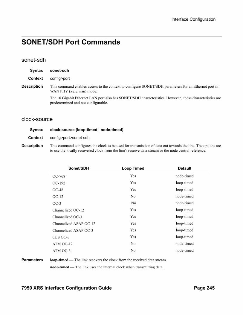
Interface Configuration
7950 XRS Interface Configuration Guide Page 245
SONET/SDH Port Commands
sonet-sdh
Syntax sonet-sdh
Context config>port
Description This command enables access to the context to configure SONET/SDH parameters for an Ethernet port in WAN PHY (xgig wan) mode.
The 10 Gigabit Ethernet LAN port also has SONET/SDH characteristics. However, these characteristics are predetermined and not configurable.
clock-source
Syntax clock-source {loop-timed | node-timed}
Context config>port>sonet-sdh
Description This command configures the clock to be used for transmission of data out towards the line. The options are to use the locally recovered clock from the line's receive data stream or the node central reference.
Parameters loop-timed — The link recovers the clock from the received data stream.
node-timed — The link uses the internal clock when transmitting data.
Sonet/SDH Loop Timed Default
OC-768 Yes node-timed
OC-192 Yes loop-timed
OC-48 Yes loop-timed
OC-12 No node-timed
OC-3 No node-timed
Channelized OC-12 Yes loop-timed
Channelized OC-3 Yes loop-timed
Channelized ASAP OC-12 Yes loop-timed
Channelized ASAP OC-3 Yes loop-timed
CES OC-3 Yes loop-timed
ATM OC-12 No node-timed
ATM OC-3 No node-timed
Interfaces
Page 246 7950 XRS Interface Configuration Guide
framing
Syntax framing {sonet | sdh}
Context config>port>sonet-sdh
Description This command specifies SONET/SDH framing to be either SONET or SDH.
Default sonet
Parameters sonet — Configures the port for SONET framing.
sdh — Configures the port for SDH framing.
report-alarm
Syntax [no] report-alarm [loc] [lais] [lrdi] [ss1f] [lb2er-sd] [lb2er-sf] [slof] [slos] [lrei]
Context config>port>sonet-sdh
Description This command enables logging of SONET (SDH) line and section alarms for a SONET-SDH port. Only line and section alarms can be configured in the SONET/SDH context, for path alarms see the sonet-sdh>path context.
The no form of this command disables logging of the specified alarms
Parameters loc — Reports a loss of clock which causes the operational state of the port to be shut down.
Default loc alarms are issued.
lais — Reports line alarm indication signal errors. When configured, lais alarms are raised and cleared.
Default lais alarms are not issued.
lrdi — Reports line remote defect indication errors. LRDI's are caused by remote LOF, LOC, LOS. When configured, lrdi alarms are raised and cleared.
Default lrdi alarms are issued.
ss1f — Reports section synchronization failure which is detected when the S1 byte is not consistent for 8 consecutive frames. When configured, ss1f alarms are raised and cleared.
Default ss1f alarms are not issued.
lb2er-sd — Reports line signal degradation BER (bit interleaved parity) errors. Use the threshold command to set the error rate(s) that when crossed determine signal degradation and signal failure. When config-ured, lb2er-sd alarms are raised and cleared.
Default lb2er-sd alarms are not issued.
lb2er-sf — Reports line signal failure BER errors. Use the threshold command to set the error rate(s) that when crossed determine signal degradation and signal failure.When configured, lb2er-sf alarms are raised and cleared.
Default lb2er-sf alarms are issued.
slof — Reports section loss of frame errors. When configured, slof alarms are raised and cleared.

Interface Configuration
7950 XRS Interface Configuration Guide Page 247
Default slof alarms are issued.
slos — Reports a section loss of signal error on the transmit side. When configured, slos alarms are raised and cleared.
Default slos alarms are issued.
lrei — Reports a line error condition raised by the remote as a result of b1 errors received from this node. When configured, lrei traps are raised but not cleared
Default lrei traps are not issued.
reset-port-on-path-down
Syntax [no] reset-port-on-path-down
Context config>port>sonet-sdh
Description This command configures whether the SONET/SDH port will reset when the path transitions to an opera-tionally down state. This command only affects SONET/SDH ports on 7750 4-port OC48 SFP “-B” MDAs.
Default no reset-port-on-path-down
section-trace
Syntax section-trace {increment-z0 | byte value | string string}
Context config>port>sonet-sdh
Description This command configures the section trace bytes in the SONET section header to interoperate with some older versions of ADMs or regenerators that require an incrementing STM ID. You can explicitly configure an incrementing STM value rather than a static one in the SDH overhead by specifying the z0-increment.
Default byte 0x1
Parameters increment-z0 — Configure an incrementing STM ID instead of a static value.
byte value — Set values in SONET header bytes.
Default 0x1
Values 0 — 255 or 0x00 — 0xFF
string string — Specifies a text string that identifies the section.
Values A string up to 16 bytes.
suppress-lo-alarm
Syntax [no] suppress-lo-alarm

Interfaces
Page 248 7950 XRS Interface Configuration Guide
Context config>port>sonet-sdh
Description This command enables the suppression of lower order alarms on SONET/SDH port.
The no form of the command disables the suppression of lower order alarms on SONET/SDH port.
tx-dus
Syntax [no] tx-dus
Context config>port>ethernet>ssmconfig>port>sonet-sdh
Description This command forces the QL value transmitted from the SSM channel of the SONET/SDH port or the Syn-chronous Ethernet port to be set to QL-DUS/QL-DNU. This capability is provided to block the use of the interface from the SR/ESS for timing purposes.
Default no tx-dus
threshold
Syntax threshold {ber-sd | ber-sf} rate threshold-rateno threshold {ber-sd | ber-sf}
Context config>port>sonet-sdh
Description This command configures the line signal degradation bit error rate (BER) and line signal failure thresholds.
Line signal (b2) bit interleaved parity error rates are measured and when they cross either the degradation or failure thresholds alarms are raised (see the report-alarm line & section command), furthermore if the failure threshold is crossed the link will be set to operationally down.
The no form of this command reverts to the default value.
Default threshold ber-sf 6 — Signal degrade BER threshold of 10-6
threshold ber-sf 3 — Signal failure BER threshold of 10-3
Parameters ber-sd — Specifies the BER that specifies signal degradation
ber-sf — Specifies the BER that specifies signal failure
threshold-rate — The BER negative exponent (n in 10-n), expressed as a decimal integer.
Values 3 — 9 (10-3 — 10-9)

Interface Configuration
7950 XRS Interface Configuration Guide Page 249
SONET/SDH Path Commands
path
Syntax [no] path [sonet-sdh-index]
Context config>port>sonet-sdh
Description This command defines the SONET/SDH path.
The no form of this command removes the specified SONET/SDH path.
Default full channel (or clear channel)
Parameters sonet-sdh-index — Specifies the components making up the specified SONET/SDH path. Depending on the type of SONET/SDH port the sonet-sdh-index must specify more path indexes to specify the payload location of the path. The sonet-sdh-index differs for SONET and SDH ports.
Values sts192
report-alarm
Syntax [no] report-alarms [pais] [plop] [prdi] [pplm] [prei] [puneq] [plcd]
Context config>port>sonet-sdh>path
Description This command enables logging of SONET (SDH) path alarms for a SONET-SDH port. Only path alarms can be configured in the channel context.
The no form of this command disables logging of the specified alarms.
Parameters pais — Reports path alarm indication signal errors. When configured, pais alarms are raised and cleared.
Default pais alarms are not issued
plop — Reports path loss of pointer (per tributary) errors. When configured, plop traps are raised but not cleared.
Default plop traps are issued
prdi — Reports path remote defect indication errors. When configured, prdi alarms are raised and cleared.
Default prdi alarms are not issued
pplm — Reports a path payload mismatch, as a result the channel will be operationally downed. When con-figured, pplm traps are raised but not cleared.
Default pplm traps are issued
prei — Reports a path error condition raised by the remote as a result of b3 errors received from this node. When configured, prei traps are raised but not cleared.
Default prei traps are not issued

Interfaces
Page 250 7950 XRS Interface Configuration Guide
puneq — Reports path unequipped errors. Reports path unequipped signal errors.
Default puneq traps are issued
plcd — Reports path loss of codegroup delineation errors. It is applicable only when the value of xgig is set to WAN.
Default plcd traps are not issued
report-alarm
Syntax [no] report-alarm {pais | plop | prdi | pplm | prei}
Context config>port>sonet-sdh>path
Description This command enables logging of SONET (SDH) path alarms for a SONET-SDH port. Only path alarms can be configured in the channel context.
The no form of this command disables logging of the specified alarms.
Parameters pais — Reports path alarm indication signal errors. When configured, pais alarms are raised and cleared.
Default pais alarms are not issued
plop — Reports path loss of pointer (per tributary) errors. When configured, plop traps are raised but not cleared.
Default plop traps are issued
prdi — Reports path remote defect indication errors. When configured, prdi alarms are raised and cleared.
Default prdi alarms are not issued
pplm — Reports a path payload mismatch, as a result the channel will be brought down. When configured, pplm traps are raised but not cleared.
Default pplm traps are issued
prei — Reports a path error condition raised by the remote as a result of b3 errors received from this node. When configured, prei traps are raised but not cleared
Default prei traps are not issued
signal-label
Syntax signal-label value
Context config>port>sonet-sdh>path
Description This command sets the C2 byte value. The purpose of this byte is to communicate the payload type being encapsulated by SONET framing.
Default 0xcf
Interface Configuration
7950 XRS Interface Configuration Guide Page 251
Parameters value — Specifies the C2 byte value, expressed as a decimal integer or a value in hex format.
Values 1 — 254 or 0x01 — 0xfe
trace-string
Syntax trace-string [trace-string]no trace-string
Context config>port> sonet-sdh>path
Description This command specifies that a J1-path-trace that identifies the circuit is inserted continuously at source. This can be checked against the expected value by the receiver. If no trace string is entered then a null string is used.
The no form of this command resets the string to its default.
Default The default J1 value is Alcatel-Lucent XXX YYY (for example, Alcatel 7750 SR) where XXX is the plat-form name, such as "7750", and YYY is the product name, such as "SR" or "ESS". The value does not change when the encap-type changes. The J1 string contains all zeros for a non-provisioned path.
Parameters trace-string — Specifies either a string up to 62 bytes for SONET or 15 bytes for SDH. If the string contains spaces, enclose it in quotation marks.
hold-time
Syntax hold-time hold-time {[up hold-time up] [down hold-time down]}no hold-time
Context config>port>tdm
Description This command configures link dampening timers in 100s of milliseconds. This guards against reporting excessive interface transitions. This is implemented by not advertising subsequent transitions of the inter-face to upper layer protocols until the configured timer has expired.
Default no hold-time
Parameters up hold-time up — Configures the hold-timer for link up event dampening. A value of zero (0) indicates that an up transition is reported immediately.
Values 0 — 100 in 100s of milliseconds (default 0)
down hold-time down — The hold-timer for link down event dampening. A value of zero (0) indicates that a down transition is reported immediately.
Values 0 — 100 in 100s of milliseconds (default 5)
This command is only supported on the m4-chds3-as, m12-chds3-as, and c4-ds3 MDAs.

Interfaces
Page 252 7950 XRS Interface Configuration Guide
LAG Commands
lag
Syntax [no] lag [lag-id]
Context config
Description This command creates the context for configuring Link Aggregation Group (LAG) attributes.
A LAG can be used to group multiple ports into one logical link. The aggregation of multiple physical links allows for load sharing and offers seamless redundancy. If one of the links fails, traffic will be redistributed over the remaining links.
NOTE: All ports in a LAG group must have autonegotiation set to Limited or Disabled.
There are three possible settings for autonegotiation:
• “on” or enabled with full port capabilities advertised
• “off” or disabled where there is no autonegotiation advertisements
• “limited” where a single speed/duplex is advertised.
When autonegotiation is enabled on a port, the link attempts to automatically negotiate the link speed and duplex parameters. If autonegotiation is enabled, the configured duplex and speed parameters are ignored.
When autonegotiation is disabled on a port, the port does not attempt to autonegotiate and will only operate at the speed and duplex settings configured for the port. Note that disabling autonegotiation on gigabit ports is not allowed as the IEEE 802.3 specification for gigabit Ethernet requires autonegotiation be enabled for far end fault indication.
If the autonegotiate limited keyword option is specified the port will autonegotiate but will only advertise a specific speed and duplex. The speed and duplex advertised are the speed and duplex settings configured for the port. One use for limited mode is for multispeed gigabit ports to force gigabit operation while keep-ing autonegotiation is enabled for compliance with IEEE 801.3.
The system requires that autonegotiation be disabled or limited for ports in a LAG to guarantee a specific port speed.
The no form of this command deletes the LAG from the configuration. Deleting a LAG can only be per-formed while the LAG is administratively shut down. Any dependencies such as IP-Interfaces configura-tions must be removed from the configuration before issuing the no lag command.
Default No LAGs are defined.
Parameters lag-id — The LAG identifier, expressed as a decimal integer.
Values 1 — 800

Interface Configuration
7950 XRS Interface Configuration Guide Page 253
access
Syntax access
Context config>lag
Description This command enables the context to configure access parameters.
adapt-qos
Syntax adapt-qos {link | port-fair | distribute [include-egr-hash-cfg]}
Context config>lag>access
Description This command specifies how the LAG SAP queue and virtual scheduler buffering and rate parameters are adapted over multiple active XMAs/MDAs. This command applies only to access LAGs.
Default distribute
Parameters Specify the QoS adaptation type:
Values link — Specifies that the LAG will create the SAP queues and virtual schedulers with the actual parameters on each LAG member port.
port-fair — Places the LAG instance into a mode that enforces QoS bandwidth constraints in the following manner: —all egress QoS objects associated with the LAG intance are created on a per port basis—bandwidth is distributed over these per port objects based on the proportion of the port's bandwidth relative to the total of all active ports bandwidth within the LAG —the include-egr-hash-cfg behavior is automatically enabled allowing the system to detect objects that hash to a single egress link in the lag and enabling full bandwidth for that object on the appropriate port
distribute — Creates an additional internal virtual scheduler per IOMXCM as parent of the configured SAP queues and vitual schedulers per LAG member port on that IOMXCM. This internal virtual scheduler limits the total amount of egress bandwidth for all member ports on the IOMXCM to the bandwidth specified in the egress qos policy.
include-egr-hash-cfg — Specifies whether explicitly configured hashing should factor into the egress buffering and rate distribution.When this parameter is configured, all SAPs on this LAG which have explicit hashing configured, the egress HQos and HPol (including queues, policers, schedulers and arbiters) will receive 100% of the configured bandwidth (essentially operating in adapt-qos link mode). For any Multi-Service-Sites assigned to such a LAG, bandwidth will continue to be divided according to adapt-qos distribute mode
A LAG instance that is currently in adapt-qos link mode may be placed at any time in port-fair mode. Similarly, a LAG instance that is currently in adapt-qos port-fair mode may be placed at any time in link mode. However, a LAG instance in adapt-qos distribute mode may not be placed into port-fair (or link) mode while QoS objects are associated

Interfaces
Page 254 7950 XRS Interface Configuration Guide
with the LAG instance. To move from distribute to port-fair mode it is necessary to remove all QoS objects from the LAG instance.
disable-soft-reset-extension
Syntax [no] disable-soft-rest-extension
Context config>lag>bfd
Description This command enables the BFD context and enables BFD over LAG links. Additional parameter configura-tion is required to make BFD over LAG links operational. Normally, BFD session timers are automatically extended during soft-reset operation on the IOMs and IMMs to avoid BFD sessions timing out and causing protocol events. However, in some cases this behavior is not desired as it could delay fast re-route transitions if they are in place. The optional disable-soft-reset-extension keyword allows this behavior to be disabled so that the BFD timers are not automatically extended.
Parameters disable-soft-reset-extension — Disables the automatic extension of BFD timers during an IOM/IMM soft-reset.
per-fp-sap-instance
Syntax [no] per-fp-sap-instance
Context config>lag>access
Description This command enables optimized SAP instance allocation on a LAG. When enabled, SAP instance is allo-cated per each FP the LAG links exits on instead of per each LAG port.
The no form of this command disables optimized SAP instance allocation.
Default no per-fp-sap-instance
per-fp-egr-queuing
Syntax [no] per-fp-egr-queuing
Context config>lag
Description This command specifies whether a more efficient method of queue allocation for LAG SAPs should be uti-lized.
The no form of the command disables the method of queue allocation for LAG SAPs.
per-fp-ing-queuing
Syntax [no] per-fp-ing-queuing
Interface Configuration
7950 XRS Interface Configuration Guide Page 255
Context config>lag
Description This command specifies whether a more efficient method of queue allocation for LAG SAPs should be uti-lized.
The no form of the command disables the method of queue allocation for LAG SAPs.
bfd
Syntax bfd
Context config>lag
Description This command creates the bfd context and enables BFD over the associated LAG links.
family
Syntax family [ipv4 | ipv6]no family
Context config>lag>bfd
Description This command is used to specify which address family should be used for the micro-BFD session over the associated LAG links.
Default None
Parameters ipv4 — IPv4 encapsulation should be used for the micro-BFD session.
ipv6 — IPv6 encapsulation should be used for the micro-BFD session.
bfd-on-distributing-only
Syntax [no] bfd-on-distributing-only
Context config>lag>bfd>family
Description This command enables restricting micro-BFD sessions to links in LACP state distributing.
The no form of the command disables restricting micro-BFD sessions
Default no bfd-on-distributing-only

Interfaces
Page 256 7950 XRS Interface Configuration Guide
local-ip-address
Syntax local-ip-address ip-addressno local-ip-address
Context config>lag>bfd>family
Description This command is used to specify the IPv4 or IPv6 address of the BFD source.
The no form of the command removes this address from the configuration.
Default no local-ip-address
Parameters ip-address — Specifies the IP address.
Values ipv4-address: a.b.c.dipv6-address: x:x:x:x:x:x:x:x (eight 16-bit pieces)
x:x:x:x:x:x:d.d.d.dx: [0 — FFFF]Hd: [0 — 255]D
max-admin-down-time
Syntax max-admin-down-time [down-interval | infinite]no max-admin-down-time
Context config>lag>bfd>family
Description This command specifies the maximum amount of time the router will continue to forward traffic over a link after the micro-BFD sessions has transitioned to a Down state because it received an ADMIN-DOWN state from the far-end. This timer provide the administrator the configured amount of time to disable or de-provi-sion the micro-BFD session on the local node before forwarding is halted over the associated link(s).
The no form of the command removes the time interval from the configuration.
Default no max-admin-down-time
Parameters down-interval — Specifies the amount of time, in seconds.
Values -1—3600
infinite — Specifies no end time to forward traffic.
max-setup-time
Syntax max-setup-time [up-interval | infinite]no max-setup-time
Context config>lag>bfd>family
Description This command specifies the maximum amount of time the router will forward traffic over a link that has transitioned from Standby to Active, before the micro-BFD session must be fully established (Up state).

Interface Configuration
7950 XRS Interface Configuration Guide Page 257
The no form of the command returns the timer value to the default (0) which indicates that forwarding will not start until the BFD session is established.
Default no max-setup-time
Parameters up-interval — Specifies the amount of time, in milliseconds.
Values -1—60000
infinite — Specifies no end time to forward traffic.
multiplier
Syntax multiplier multiplierno multiplier
Context config>lag>bfd>family
Description This command specifies the detect multiplier used for a micro-BFD session over the associated LAG links. If a BFD control packet is not received for a period of multiplier X receive-interval then the session is declared down.
The no form of the command removes multiplier from the configuration.
Default no multiplier
Parameters multiplier — Specifies the multiplier value.
Values 3—20
receive-interval
Syntax receive-interval receive-intervalno receive-interval
Context config>lag>bfd>family
Description This command specifies the receive timer used for micro-BFD session over the associated LAG links.
The no form of the command removes the receive timer from the configuration.
Default no receive-interval
Parameters receive-interval — Specifies the interval value, in milliseconds.
Values 10—100000
Default 100 ms for CPM3 or later, 1 sec for all other

Interfaces
Page 258 7950 XRS Interface Configuration Guide
remote-ip-address
Syntax remote-ip-address ip-addressno remote-ip-address
Context config>lag>bfd>family
Description This command is used to specify the IPv4 or IPv6 address of the BFD destination.
The no form of the command removes this address from the configuration.
Default no remote-ip-address
Parameters ip-address — Specifies the IP address.
Values ipv4-address: a.b.c.dipv6-address: x:x:x:x:x:x:x:x (eight 16-bit pieces)
x:x:x:x:x:x:d.d.d.dx: [0 — FFFF]Hd: [0 — 255]D
transmit-interval
Syntax transmit-interval transmit-intervalno transmit-interval
Context config>lag>bfd>family
Description This command specifies the transmit timer used for micro-BFD session over the associated LAG links.
The no form of the command removes the transmit timer from the configuration.
Default no transmit-interval
Parameters transmit-interval — Specifies the interval value, in milliseconds.
Values 10—100000
Default 100 ms for CPM3 or later, 1 sec for all other
shutdown
Syntax shutdownno shutdown
Context config>lag>bfd>family
Description This command disables micro BFD sessions for this address family.
The no form of the command re-enables micro BFD sessions for this address family.
Default no transmit-interval

Interface Configuration
7950 XRS Interface Configuration Guide Page 259
dynamic-cost
Syntax [no] dynamic-cost
Context config>lag lag-id
Description This command enables OSPF/ISIS costing of a Link Aggregation Group (LAG) based on the available aggregated, operational bandwidth.
The path cost is dynamically calculated based on the interface bandwidth. OSPF path cost can be changed through the interface metric or the reference bandwidth.
If dynamic cost is configured, then costing is applied based on the total number of links configured and the cost advertised is inversely proportional to the number of links available at the time. This is provided that the number of links that are up exceeds the configured LAG threshold value at which time the configured threshold action determines if, and at what cost, this LAG will be advertised.
For example:
Assume a physical link in OSPF has a cost associated with it of 100, and the LAG consists of four phys-ical links. The cost associated with the logical link is 25. If one link fails then the cost would automati-cally be adjusted to 33.
If dynamic cost is not configured and OSPF autocost is configured, then costing is applied based on the total number of links configured. This cost will remain static provided the number of links that are up exceeds the configured LAG threshold value at which time the configured threshold action determines if and at what cost this LAG will be advertised.
If dynamic-cost is configured and OSPF autocost is not configured, the cost is determined by the cost con-figured on the OSPF metric provided the number of links available exceeds the configured LAG threshold value at which time the configured threshold action determines if this LAG will be advertised.
If neither dynamic-cost nor OSPF autocost are configured, the cost advertised is determined by the cost con-figured on the OSPF metric provided the number of links available exceeds the configured LAG threshold value at which time the configured threshold action determines if this LAG will be advertised.
The no form of this command removes dynamic costing from the LAG.
Default no dynamic-cost
encap-type
Syntax encap-type {dot1q | null | qinq}no encap-type
Context config>lag
Description This command configures the encapsulation method used to distinguish customer traffic on a LAG. The encapsulation type is configurable on a LAG port. The LAG port and the port member encapsulation types must match when adding a port member.
If the encapsulation type of the LAG port is changed, the encapsulation type on all the port members will also change. The encapsulation type can be changed on the LAG port only if there is no interface associated

Interfaces
Page 260 7950 XRS Interface Configuration Guide
with it. If the MTU is set to a non default value, it will be reset to the default value when the encap type is changed.
The no form of this command restores the default.
Default null — All traffic on the port belongs to a single service or VLAN.
Parameters dot1q — Ingress frames carry 802.1Q tags where each tag signifies a different service.
null — Ingress frames will not use any tags to delineate a service. As a result, only one service can be con-figured on a port with a null encapsulation type.
qinq — Specifies QinQ encapsulation.
hold-time
Syntax hold-time down hold-down-timeno hold-time
Context config>lag
Description This command specifies the timer, in tenths of seconds, which controls the delay between detecting that a LAG is down (all active ports are down) and reporting it to the higher levels.
A non-zero value can be configured, for example, when active/standby signalling is used in a 1:1 fashion to avoid informing higher levels during the small time interval between detecting that the LAG is down and the time needed to activate the standby link.
Default 0
Parameters down hold-down-time — Specifies the hold-time for event reporting
Values 0 — 2000
lacp
Syntax lacp [mode] [administrative-key admin-key] [system-id system-id][system-priority priority]
Context config>lag
Description This command specifies the LACP mode for aggregated Ethernet interfaces only. This command enables the LACP protocol. Per the IEEE 802.1ax standard, the Link Aggregation Control Protocol (LACP) provides a standardized means for exchanging information between Partner Systems on a link to allow their Link Aggregation Control instances to reach agreement on the identity of the Link Aggregation Group to which the link belongs, move the link to that Link Aggregation Group, and enable its transmission and reception functions in an orderly manner.
Default no lacp
Parameters Note: If any of the parameters are omitted, the existing configuration is preserved. The default parameter values are used if a parameter is never explicitly configured.

Interface Configuration
7950 XRS Interface Configuration Guide Page 261
mode — Specifies the mode in which LACP will operate.
Values passive — Starts transmitting LACP packets only after receiving packets. active — Initiates the transmission of LACP packets.
administrative-key admin-key — Specifies an administrative key value to identify the channel group on each port configured to use LACP. This value should be configured only in exceptional cases. A random key is assigned by default if a value is not specified.
Values 1 — 65535
system-priority priority — Specifies the system priority.
Values 1 — 65535
Default 32768
lacp-mux-control
Syntax lacp-mux-control {coupled | independent}no lacp-mux-control
Context config>lag
Description This command configures the type of multiplexing machine control to be used in a LAG with LACP in active/passive modes.
The no form of the command disables multiplexing machine control.
Default coupled
Parameters coupled — TX and RX activate together.
independent — RX activates independent of TX.
lacp-xmit-interval
Syntax lacp-xmit-interval {slow | fast}
Context config>lag
Description This command specifies the interval signaled to the peer and tells the peer at which rate it should transmit.
Default fast
Parameters slow — Transmits packets every 30 seconds.
fast — Transmits packets every second.
lacp-xmit-stdby
Syntax [no] lacp-xmit-stdby

Interfaces
Page 262 7950 XRS Interface Configuration Guide
Context config>lag
Description This command enables LACP message transmission on standby links.
The no form of this command disables LACP message transmission. This command should be disabled for compatibility when using active/standby groups. This forces a timeout of the standby links by the peer. Use the no form if the peer does not implement the correct behavior regarding the lacp sync bit.
Default lacp-xmit-stdby
link-map-profile
Syntax link-map-profile link-map-profile-id [create]no link-map-profile link-map-profile-id
Context config>lag
Description This command creates the link map profile that can to control which LAG ports are to be used on egress or enables the configuration context for previously created link map profile.
The no form of this command, deletes the specified link map profile.
Default Link-map-profiles are not created by default.
Parameters link-map-profile-id — An integer from 1 to 64 that defines a unique lag link map profile on this LAG.
link
Syntax link port-id {primary|secondary}no primary-link
Context config>lag>link>map>profile
Description This command designates one of the configured ports of the LAG to be used on egress as either a primary or secondary link (based on the option selected) by all SAPs/network interfaces that use this LAG link map profile.
The no form of this command deletes the link from this LAG link mapping profile. A port must be deleted from all lag link profiles if it is to be deleted from the LAG.
Default Links are part of a profile.
Notes When a link gets added/deleted, all SAPs/network interfaces that use this link-map-profile may be re-hashed if required.
Parameters port-id — A physical port Id in the slot/mda/port format that is an existing member of this LAG.
primary — Designates one of the configured ports of the LAG to be used on egress as a primary link by SAPs/network interfaces that use this LAG link map profile.
secondary — Designates one of the configured ports of the LAG to be used on egress as a secondary link by SAPs/network interfaces that use this LAG link map profile.

Interface Configuration
7950 XRS Interface Configuration Guide Page 263
failure-mode
Syntax failure-mode [discard | per-link-hash]no failure-mode
Context config>lag>link>map>profile
Description This command defines the failure mode for egress traffic of SAPs/network interfaces that use this link-map-profile when neither primary nor secondary links of this profile are available.
Options include:
• discard – egress traffic for SAPs/network interfaces using this link-map-profile is discarded to protect SAP/network interface traffic on other LAG links from impact of re-hashing the affected SAPs/network interfaces
• per-link-hash – egress traffic for SAPs/network interfaces using this link-map-profile is rehashed on remaining, available LAG links using per-link-hash algorithm. SAP/network interface QoS configurations dictate what traffic is discarded on any link that may become oversubscribed as result of the re-hash.
The no form of this command restores the default failure-mode value.
Default failure-mode per-link-hash
port
Syntax port port-id [port-id … ] [priority priority] [subgroup sub-group-id]no port port-id [port-id … ]
Context config>lag>port
Description This command adds ports to a Link Aggregation Group (LAG).
The port configuration of the first port added to the LAG is used as a basis to compare to subsequently added ports. If a discrepancy is found with a newly added port, that port will not be added to the LAG.
Multiple (space separated) ports can be added or removed from the LAG link assuming the maximum of number of ports is not exceeded.
Ports that are part of a LAG must be configured with auto-negotiate limited or disabled.
The no form of this command removes ports from the LAG.
Default No ports are defined as members of a LAG.
Parameters port-id — The port ID configured or displayed in the slot/mda/port format.
Note that the maximum number of ports in a LAG depends on platform-type, H/W deployed, and SROS S/W release. Adding a port over the maximum allowed per given router/switch is blocked. Some plat-forms support double port scale for some port types on LAGs with lag-id in the range of 1-64 inclusive.
Values slot/mda/port
priority priority — Port priority used by LACP. The port priority is also used to determine the primary port. The port with the lowest priority is the primary port. In the event of a tie, the smallest port ID becomes

Interfaces
Page 264 7950 XRS Interface Configuration Guide
the primary port.
Values 1 — 65535
subgroup sub-group-id — This parameter identifies a LAG subgroup. When using subgroups in a LAG, they should only be configured on one side of the LAG, not both. Only having one side perform the active/standby selection will guarantee a consistent selection and fast convergence. The active/standby selection will be signalled through LACP to the other side. The hold time should be configured when using subgroups to prevent the LAG going down when switching between active and standby subgroup since momentarily all ports are down in a LAG (break-before-make).
Values 1 — 8 identifies a LAG subgroup.The auto-iom subgroup is defined based on the IOM (all ports of the same IOM are assigned to the same subgroup).The auto-mda subgroup is defined based on the MDA. (all ports of the same MDA are assigned to the same subgroup).
port-threshold
Syntax port-threshold value [action {dynamic-cost | down}no port-threshold
Context config>lag lag-id
Description This command configures the behavior for the Link Aggregation Group (LAG) if the number of operational links is equal to or below a threshold level.
The no form of this command reverts to the default values.
Default 0 action down
Parameters value — The decimal integer threshold number of operational links for the LAG at or below which the con-figured action will be invoked. If the number of operational links exceeds the port-threshold value, any action taken for being below the threshold value will cease.
Values 0 — 63
action {dynamic-cost | down} — Specifies the action to take if the number of active links in the LAG is at or below the threshold value.
When the dynamic-cost action is specified, then dynamic costing will be activated. As a result the LAG will remain operationally up with a cost relative to the number of operational links. The link will only be regarded as operationally down when all links in the LAG are down.
When the down action is specified, then the LAG will be brought operationally down if the number of operational links is equal to or less than the configured threshold value. The LAG will only be regarded as up once the number of operational links exceeds the configured threshold value.
port-weight-speed
Syntax port-weight-speed {1 | 10}

Interface Configuration
7950 XRS Interface Configuration Guide Page 265
no port-weight-speed
Context config>lag
Description This command enables mixed port-speed LAG operation.
Parameter specified with the command defines what type of ports are allowed in a LAG, and what is the weight of each port for total LAG weight calculation:
no port-weight-speed – all LAG links must be of the same speed. Each link weight is 1.
Parameters port-weight-speed 1 – LAG supports any mix of 1GE, 10GE ports up to a total weight of 64 (for 64 link LAGs) or 32 (for 32 link LAGs). Each 1 GE port has a weight of 1; each 10GE port has a weight of 10.
port-weight-speed 10 – LAG supports any mix of 10GE, 40GE, 100GE ports up to a total weight of 64 (for 64 link LAGs) or 32 (for 32 link LAGs). Each 10 GE port has a weight of 1; each 40GE port has a weight of 4; each 100GE port has a weight of 10.
For existing LAGs:
no port-weight-speed can be changed to port-weight-speed 1 or port-weight-speed 10 in service, when all links of the LAG are 1GE or 10GE respectively.
port-weight-speed 1 or port-weight-speed 10 can be changed to no port-weight-speed in service, when all links of the LAG are 1GE or 10GE respectively.
All other configuration changes require shutdown of the LAG and removal of all ports first.
Default no port-weight-speed
selection-criteria
Syntax selection-criteria {highest-count | highest-weight | best-port} [slave-to-partner] [subgroup-hold-time hold-time]no selection-criteria
Context config>lag
Description This command specifies which selection criteria should be used to select the active sub-group.
Default highest-count
Parameters highest-count — Selects a sub-group with the highest number of eligible members as an active sub-group (not applicable to “power-off” mode of operations).
highest-weight — Selects a sub-group with the highest aggregate weight as an active subgroup (not applica-ble to “power-off” mode of operations).
best-port — Selects a sub-group containing the port with highest priority port as an active subgroup. In case of equal port priorities, the sub-group containing the port with the lowest port-id is chosen.
slave-to-partner — The slave-to-partner keyword specifies that it, together with the selection criteria, should be used to select the active sub-group. An eligible member is a lag-member link which can potentially become active. This means it is operationally up (not disabled) for use by the remote side.
Interfaces
Page 266 7950 XRS Interface Configuration Guide
The slave-to-partner parameter can be used to control whether or not this latter condition is taken into account.
subgroup-hold-time hold-time — Applicable with LACP enabled. Specifies the optional delay timer for switching to a newly selected active sub-group from the existing active sub-group. The timer delay applies only if the existing sub-group remains operationally up.
Values not specified – Equivalent to specifying a value of 0. Specifies no delay and to switchover immediately to a new candidate active sub-group.
Values 0..2000 – Integer specifying the timer value in 10ths of a second.
Values infinite – Do not switchover from existing active sub-group if the subgroup remains UP. Manual switchover possible using tools perform lag force command.
standby-signalling
Syntax standby-signalling {lacp | power-off}no standby-signalling
Context config>lag
Description This command specifies how the state of a member port is signalled to the remote side when the status cor-responding to this member port has the standby value.
weight-threshold
Syntax weight-threshold value action [{dynamic-cost | down}]no weight-threshold
Context config>lag
Description This command configures the behavior for the Link Aggregation Group (LAG) if the total weight of opera-tional links is equal to or below the configured threshold level. The command can be used for mixed port-speed LAGs and for LAGs with all ports of equal speed.
The no form of this command disabled weight-threshold operation in LAG.
Default no weight-threshold
Parameters value — 0..63
action { dynamic-cost | down} — Specifies the action to take if the total weight of active links in the LAG is at or below the threshold value. When the dynamic-cost action is specified then dynamic costing will be activated. As a result the LAG will remain operationally up with a cost relative to the number of operational links. The link will only be regarded as operationally down when all links in the LAG are down. When the down action is specified then the LAG will be brought operationally down if the total weight of operational links is equal to or less than the configured threshold value. The LAG will only be regarded as up once the total weight of operational links exceeds the configured threshold value.

Interface Configuration
7950 XRS Interface Configuration Guide Page 267
ETH-CFM Configuration Commands
eth-cfm
Syntax eth-cfm
Context config>port>ethernetconfig>lag
Description This command enables the context to configure 802.1ag CFM parameters.
mep
Syntax mep mep-id domain md-index association ma-index [vlan vlan-id]no mep mep-id domain md-index association ma-index [vlan vlan-id]
Context config>port>ethernet>eth-cfmconfig>lag>eth-cfmconfig>router>if>eth-cfm
Description This command provisions the maintenance endpoint (MEP).
The no form of the command reverts to the default values.
Parameters mep-id — Specifies the maintenance association end point identifier.
Values 1 — 81921
md-index — Specifies the maintenance domain (MD) index value.
Values 1 — 4294967295
ma-index — Specifies the MA index value.
Values 1 — 4294967295
vlan-id — Specific to tunnel facility MEPs which means this option is only applicable to the lag>eth-cfm> context. Used to specify the outer vlan id of the tunnel.
Values 1 — 4094
ais-enable
Syntax [no] ais-enable
Context config>port>ethernet>eth-cfm>mepconfig>lag>eth-cfm>mep
Interfaces
Page 268 7950 XRS Interface Configuration Guide
Description This command enables the reception of AIS messages.
The no form of the command reverts to the default values.
client-meg-level
Syntax client-meg-level [[level [level ...]]no client-meg-level
Context config>port>ethernet>eth-cfm>mep>ais-enableconfig>lag>eth-cfm> mep>ais-enable
Description This command configures the client maintenance entity group (MEG) level(s) to use for AIS message gener-ation. Up to 7 levels can be provisioned with the restriction that the client MEG level must be higher than the local MEG level. Only the lowest client MEG level will be used for facility MEPs.
The no form of the command reverts to the default values.
Parameters level — Specifies the client MEG level.
Values 1 — 7
Default 1
interval
Syntax interval {1 | 60} no interval
Context config>port>ethernet>eth-cfm>mep>ais-enableconfig>lag>eth-cfm> mep>ais-enable
Description This command specifies the transmission interval of AIS messages in seconds.
The no form of the command reverts to the default values.
Parameters 1 | 60 — The transmission interval of AIS messages in seconds.
Default 1
priority
Syntax priority priority-valueno priority
Context config>port>ethernet>eth-cfm>mep>ais-enableconfig>lag>eth-cfm> mep>ais-enable
Description This command specifies the priority of the AIS messages generated by the node.
The no form of the command reverts to the default values.

Interface Configuration
7950 XRS Interface Configuration Guide Page 269
Parameters priority-value — Specify the priority value of the AIS messages originated by the node.
Values 0 — 7
Default 7
ccm-enable
Syntax [no] ccm-enable
Context config>port>ethernet>eth-cfm>mepconfig>lag>eth-cfm>mep
Description This command enables the generation of CCM messages.
The no form of the command disables the generation of CCM messages.
ccm-ltm-priority
Syntax ccm-ltm-priority priorityno ccm-ltm-priority
Context config>port>ethernet>eth-cfm>mep>config>lag>eth-cfm>mep>config>router>if>eth-cfm>mep
Description This command specifies the priority of the CCM and LTM messages transmitted by the MEP. Since CCM does not apply to the Router Facility MEP only the LTM priority is of value under that context.
The no form of the command reverts to the default values.
Default priority — Specifies the priority value
Values 0 — 7
Default 7
ccm-padding-size
Syntax ccm-padding-size ccm-paddingno ccm-padding-size
Context config>eth-tunnel>path>eth-cfm>mep
Description This command inserts additional padding in the CCM packets.
The no form of the command reverts to the default.
Parameters ccm-padding — Specifies the additional padding in the CCM packets.
Values 3 — 1500 octets

Interfaces
Page 270 7950 XRS Interface Configuration Guide
ccm-tlv-ignore
Syntax ccm-tlv-ignore [port-status] [interface-status]no ccm-tlv-ignore
Context config>port>ethernet>eth-cfm>mepconfig>lag>eth-cfm>mep
Description This command allows the receiving MEP to ignore the specified TLVs in CCM PDU. Ignored TLVs will be reported as absent and will have no impact on the MEP state machine.
The no form of the command causes the receiving MEP will process all recognized TLVs in the CCM PDU.
Parameters port-status — Ignore the port status TLV on reception.
interface-status — ignore the interface status TLV on reception.
collect-lmm-stats
Syntax collect-lmm-stats[no] collect-lmm-stats
Context config>port>ethernet>eth-cfm>mep config>router>if>eth-cfm>mepconfig>lag>eth-cfm>mep
Description This command enables the collection of statistics on the facility MEPs. This command is an object under the Facility MEP. This is at a different level of the hierarchy than collection of lmm statistics for service SAPs and MPLS SDP Bindings. The show mep command can be used to determine is the Facility MEP is collecting stats.
The no form of the command disables and deletes the counters for this SAP, Binding or facility.
Default no collect-lmm-stats
eth-test-enable
Syntax [no] eth-test-enable
Context config>port>ethernet>eth-cfm>mepconfig>lag>eth-cfm>mepconfig>router>if>eth-cfm>mep
Description For this test to work, operators need to configure ETH-test parameters on both sender and receiver nodes. The ETH-test then can be done using the following OAM commands:
oam eth-cfm eth-test mac-address mep mep-id domain md-index association ma-index [priority priority] [data-length data-length]
The no form of the command disables eth-test capabilities.

Interface Configuration
7950 XRS Interface Configuration Guide Page 271
bit-error-threshold
Syntax bit-error-threshold bit-errors
Context config>eth-ring>path>eth-cfm>mep
Description This command specifies the lowest priority defect that is allowed to generate a fault alarm.
Default 1
Parameters bit-errors — Specifies the lowest priority defect.
Values 0 — 11840
test-pattern
Syntax test-pattern {all-zeros | all-ones} [crc-enable]no test-pattern
Context config>port>ethernet>eth-cfm>mep>eth-testconfig>lag>eth-cfm>mep>eth-testconfig>router>if>eth-cfm>mep>eth-test
Description This command specifies the test pattern of the ETH-TEST frames. This does not have to be configured the same on the sender and the receiver.
The no form of the command reverts to the default values.
Parameters all-zeros — Specifies to use all zeros in the test pattern.
all-ones — Specifies to use all ones in the test pattern.
crc-enable — Generates a CRC checksum.
Default all-zeros
low-priority-defect
Syntax low-priority-defect {allDef | macRemErrXcon | remErrXcon | errXcon | xcon | noXcon}
Context config>port>ethernet>eth-cfm>mep>eth-testconfig>lag>eth-cfm>mep>eth-test
Description This command specifies the lowest priority defect that is allowed to generate a fault alarm. This setting is also used to determine the fault state of the MEP which, well enabled to do so, causes a network reaction.
Default macRemErrXcon
Values allDef DefRDICCM, DefMACstatus, DefRemoteCCM, DefErrorCCM, and DefXconCCM
macRemErrXconOnly DefMACstatus, DefRemoteCCM, DefErrorCCM, and

Interfaces
Page 272 7950 XRS Interface Configuration Guide
DefXconCCMremErrXcon Only DefRemoteCCM, DefErrorCCM, and DefXconCCMerrXcon Only DefErrorCCM and DefXconCCMxcon Only DefXconCCM; or noXcon No defects DefXcon or lower are to be reported
mac-address
Syntax mac-address mac-addressno mac-address
Context config>port>ethernet>eth-cfm>mepconfig>lag>eth-cfm>mepconfig>router>if>eth-cfm>mep
Description This command specifies the MAC address of the MEP.
The no form of the command reverts to the MAC address of the MEP back to the default, that of the port, since this is SAP based.
Default no mac-address
Parameters mac-address — Specifies the MAC address of the MEP.
Values 6-byte unicast mac-address (xx:xx:xx:xx:xx:xx or xx-xx-xx-xx-xx-xx) of the MEP. Using the all zeros address is equivalent to the no form of this command.
one-way-delay-threshold
Syntax one-way-delay-threshold seconds
Context config>eth-tunnel>path>eth-cfm>mep
Description This command enables one way delay threshold time limit.
Default 3 seconds
Parameters seconds — Specifies the value, in seconds, for the threshold.
Values 0 — 600
facility-fault
Syntax [no] facility-fault
Context config>lag>eth-cfm>mepconfig>port>ethernet>eth-cfm>mep

Interface Configuration
7950 XRS Interface Configuration Guide Page 273
Description Allows the facility MEP to move from alarming only to network actionable function. This means a facility MEP will not merely report the defect conditions but will be able to action based on the transition of the MEP state. Without this command the facility MEP will only monitor and report and conditions of the MEP do not affect related services.
Default no facility-fault
tunnel-fault
Syntax tunnel-fault {accept | ignore}
Context config>service>vpls>eth-cfmconfig>service>vpls>sap>eth-cfmconfig>service>epipe>eth-cfmconfig>service>epipe>sap>eth-cfmconfig>service>ipipe>eth-cfmconfig>service>ipipe>sap>eth-cfmconfig>service>ies>eth-cfmconfig>service>ies>if>sap>eth-cfmconfig>service>ies>sub-if>grp-if>sap>eth-cfmconfig>service>vprn>eth-cfmconfig>service>vprn>if>sap>eth-cfmconfig>service>vprn>sub-if>grp-if>sap>eth-cfm
Description Allows the individual service SAPs to react to changes in the tunnel MEP state. When tunnel-fault accept is configured at the service level, the SAP will react according to the service type, Epipe will set the opera-tional flag and VPLS, IES and VPRN SAP operational state will become down on failure or up on clear. This command triggers the OAM mapping functions to mate SAPs and bindings in an Epipe service as well as setting the operational flag. If AIS generation is the requirement for the Epipe services this command is not required. See the ais-enable command under the config>service>epipe>sap>eth-cfm>ais-enable con-text for more details. This works in conjunction with the tunnel-fault accept on the individual SAPs. Both must be set to accept to react to the tunnel MEP state. By default the service level command is “ignore” and the SAP level command is “accept”. This means simply changing the service level command to “accept” will enable the feature for all SAPs. This is not required for Epipe services that only wish to generate AIS on failure.
Parameters accept — Share fate with the facility tunnel MEP
ignore — Do not share fate with the facility tunnel MEP
Default ignore (Service Level)
accept (SAP Level for Epipe and VPLS)

Interfaces
Page 274 7950 XRS Interface Configuration Guide
Multi-Chassis Redundancy Commands
redundancy
Syntax redundancy
Context config
Description This command allows the user to perform redundancy operations.
Associated commands include the following in the admin>redundancy context:
force-switchover — Forces a switchover to the standby CPM/CFM card.
now — Switch to standby CPM/CFM.
NOTE: Switching to the standby displays the following message.
WARNING: Configuration and/or Boot options may have changed since the last save.Are you sure you want to switchover (y/n)?
synchronize — Synchronizes the secondary CPM/CFM.
Values <boot-env|config> : keywords
Refer to the 7950 XRS OS Basic System Configuration Guide.
synchronize
Syntax synchronize {boot-env | config}
Context config>redundancy
Description This command performs a synchronization of the standby CPM/CFM’s images and/or config files to the active CPM/CFM. Either the boot-env or config parameter must be specified.
In the config>redundancy context, this command performs an automatically triggered standby CPM/CFM synchronization.
When the standby CPM/CFM takes over operation following a failure or reset of the active CPM/CFM, it is important to ensure that the active and standby CPM/CFMs have identical operational parameters. This includes the saved configuration, CPM and IOM images.This includes the saved configuration, CPM and IOM images.This includes the saved configuration and CFM images. The active CPM/CFM ensures that the active configuration is maintained on the standby CPM/CFM. How-ever, to ensure smooth operation under all circumstances, runtime images and system initialization configu-rations must also be automatically synchronized between the active and standby CPM/CFM.
If synchronization fails, alarms and log messages that indicate the type of error that caused the failure of the synchronization operation are generated. When the error condition ceases to exist, the alarm is cleared.

Interface Configuration
7950 XRS Interface Configuration Guide Page 275
Only files stored on the router are synchronized. If a configuration file or image is stored in a location other than on a local compact flash, the file is not synchronized (for example, storing a configuration file on an FTP server).
Default enabled
Parameters boot-env — Synchronizes all files required for the boot process (loader, BOF, images, and configuration files.
config — Synchronize only the primary, secondary, and tertiary configuration files.
Default config
bgp-multi-homing
Syntax bgp-multi-homing
Context config>redundancy
Description This command configures BGP multi-homing parameters.
boot-timer
Syntax boot-timer secondsno boot-timer
Context config>redundancy>bgp-mh
Description This command specifies how long the service manager waits after a node reboot before running the MH pro-cedures. The boot-timer value should be configured to allow for the BGP sessions to come up and for the NLRI information to be refreshed/exchanged. The boot-timer is activated after the no shutdown command for a MH site executed from configuration. Upon activation, the boot-timer is compared with the system up-time for the node. If the boot timer is higher than the up-time, then the service manager waits for the boot-timer-sys-up-time, then starts the site-activation-timer.
The no form of this command sets the value to 10.
Default 10 sec
Parameters seconds — Specifies the timer, in seconds.
Values 1..100
site-activation-timer
Syntax site-activation-timer secondsno site-activation-timer
Context config>redundancy>bgp-mh

Interfaces
Page 276 7950 XRS Interface Configuration Guide
Description This command defines the amount of time the service manager will keep the local sites in standby status, waiting for BGP updates from remote PEs before running the DF election algorithm to decide whether the site should be unblocked. THe timer is started when one of the following event occurs only if the site is operationally up:
• Manual site activation using “no shutdown” at site-id level or at member object(s) level (for example, SAP(s) or PW(s)
• Site activation after a failure
The no form of this command sets the value to 2.
Default 2 seconds
Parameters seconds — Specifies the timer, in seconds.
Values 1..100
site-min-down-timer
Syntax site-min-down-timer min-down-timeno site-min-down-timer
Context config>redundancy>bgp-multi-homing
Description This command configures the BGP multi-homing site minimum down time. When set to a non-zero value, if the site goes operationally down it will remain operationally down for at least the length of time configured for the site-min-down-timer, regardless of whether other state changes would have caused it to go operationally up. This timer is restarted every time that the site transitions from up to down.
The above operation is optimized in the following circumstances:
• If the site goes down on the designated forwarder but there are no BGP multi-homing peers with the same site in an UP state, then the site-min-down-timer is not started and is not used.
• If the site goes down on the designated forwarder but there are no active BGP multi-homing peers, then the site-min-down-timer is not started and is not used.
• If the site-min-down-timer is active and a BGP multi-homing update is received from the designated forwarder indicating its site has gone down, the site-min-down-timer is immediately terminated and this PE becomes the designated forwarder if the BGP multi-homing algorithm determines it should be the designated forwarder.
The no form of the command reverts to default value.
Default no site-min-down-timer
Parameters min-down-time — Specifies the time, in seconds, that a BGP multi-homing site remains operationally down after a transition from up to down.
Values 1— 100 seconds
Default 0 seconds

Interface Configuration
7950 XRS Interface Configuration Guide Page 277
multi-chassis
Syntax multi-chassis
Context config>redundancy
Description This command enables the context to configure multi-chassis parameters.
peer
Syntax [no] peer ip-address create
Context config>redundancy>multi-chassis
Description Use this command to configure up to 20 multi-chassis redundancy peers. Note that it is only for mc-lag (20) not for mc-sync (4).
Parameters ip-address — Specifies the IP address.
Values ipv4-address: a.b.c.dipv6-address: x:x:x:x:x:x:x:x (eight 16-bit pieces)
x:x:x:x:x:x:d.d.d.dx: [0 — FFFF]Hd: [0 — 255]D
create — Mandatory keyword specifies to create the peer.
authentication-key
Syntax authentication-key [authentication-key | hash-key] [hash | hash2]no authentication-key
Context config>redundancy>multi-chassis>peer
Description This command configures the authentication key used between this node and the multi-chassis peer. The authentication key can be any combination of letters or numbers.
Parameters authentication-key — Specifies the authentication key. Allowed values are any string up to 20 characters long composed of printable, 7-bit ASCII characters. If the string contains special characters (#, $, spaces, etc.), the entire string must be enclosed within double quotes.
hash-key — The hash key. The key can be any combination of ASCII characters up to 33 (hash1-key) or 55 (hash2-key) characters in length (encrypted). If spaces are used in the string, enclose the entire string in quotation marks (“ ”).
hash — Specifies the key is entered in an encrypted form. If the hash or hash2 parameter is not used, the key is assumed to be in a non-encrypted, clear text form. For security, all keys are stored in encrypted form in the configuration file with the hash or hash2 parameter specified.
hash2 — Specifies the key is entered in a more complex encrypted form that involves more variables then the key value alone, this means that hash2 encrypted variable cannot be copied and pasted. If the hash or

Interfaces
Page 278 7950 XRS Interface Configuration Guide
hash2 parameter is not used, the key is assumed to be in a non-encrypted, clear text form. For security, all keys are stored in encrypted form in the configuration file with the hash or hash2 parameter speci-fied.
Interface Configuration
7950 XRS Interface Configuration Guide Page 279
MC Endpoint Commands
mc-endpoint
Syntax [no] mc-endpoint
Context config>redundancy>multi-chassis>peer
Description This command specifies that the endpoint is multi-chassis. This value should be the same on both MC-EP peers for the pseudowires that must be part of the same group.
The no form of this command removes the endpoint from the MC-EP. Single chassis behavior applies.
bfd-enable
Syntax [no] bfd-enable
Context config>redundancy>multi-chassis>peer>mc-epconfig>router>rsvpconfig>router>bgpconfig>router>bgp>groupconfig>router>bgp>group>neighborconfig>redundancy>multi-chassis>peer>mc-ep
Description This command enables the use of bi-directional forwarding (BFD) to control the state of the associated pro-tocol interface. By enabling BFD on a given protocol interface, the state of the protocol interface is tied to the state of the BFD session between the local node and the remote node. The parameters used for the BFD are set via the BFD command under the IP interface.
The no form of this command disables BFD.
Default no bfd-enable
boot-timer
Syntax boot-timer interval no boot-timer
Context config>redundancy>multi-chassis>peer>mc-ep
Description This command configures the boot timer interval. This command applies only when the node reboots. It specifies the time the MC-EP protocol keeps trying to establish a connection before assuming a failure of the remote peer. This is different from the keep-alives mechanism which is used just after the peer-peer commu-nication was established. After this time interval passed all the mc-endpoints configured under services will revert to single chassis behavior, activating the best local PW.
The no form of this command sets the interval to default.

Interfaces
Page 280 7950 XRS Interface Configuration Guide
Default 300
Parameters interval — Specifies the boot timer interval.
Values 1 — 600
hold-on-neighbor-failure
Syntax hold-on-neighbor-failure multiplier no hold-on-neighbor-failure
Context config>redundancy>multi-chassis>peer>mc-ep
Description This command specifies the number of keep-alive intervals that the local node will wait for packets from the MC-EP peer before assuming failure. After this time interval passed the all the mc-endpoints configured under services will revert to single chassis behavior, activating the best local pseudowire.
The no form of this command sets the multiplier to default value
Default 3
Parameters multiplier — Specifies the hold time applied on neighbor failure.
Values 2 — 25
keep-alive-interval
Syntax keep-alive-interval interval no keep-alive-interval
Context config>redundancy>multi-chassis>peer>mc-ep
Description This command sets the interval at which keep-alive messages are exchanged between two systems partici-pating in MC-EP when bfd is not enabled or is down. These fast keep-alive messages are used to determine remote-node failure and the interval is set in deci-seconds.
The no form of this command sets the interval to default value
Default 5 (0.5s)
Parameters interval — The time interval expressed in deci-seconds.
Values 5 — 500 (tenths of a second)

Interface Configuration
7950 XRS Interface Configuration Guide Page 281
passive-mode
Syntax [no] passive-mode
Context config>redundancy>multi-chassis>peer>mc-ep
Description This command configures the passive mode behavior for the MC-EP protocol. When in passive mode the MC-EP pair will be dormant until two of the pseudowires in a MC-EP will be signaled as active by the remote PEs, being assumed that the remote pair is configured with regular MC-EP. As soon as more than one pseudowire is active, dormant MC-EP pair will activate. It will use the regular exchange to select the best pseudowire between the active ones and it will block the Rx and Tx directions of the other pseudowires.
The no form of this command will disable the passive mode behavior.
Default no passive-mode
system-priority
Syntax system-priority valueno system-priority
Context config>redundancy>multi-chassis>peer>mc-ep
Description This command allows the operator to set the system priority. The peer configured with the highest value is chosen to be the Master. If system-priority are equal then the one with the lowest system-id (chassis MAC address) is chosen as the Master.
The no form of this command sets the system priority to default
Default 0
Parameters value — Specifies the priority assigned to the local MC-EP peer.
Values 1— 255

Interfaces
Page 282 7950 XRS Interface Configuration Guide
MC LAG Commands
mc-lag
Syntax [no] mc-lag
Context config>redundancy>multi-chassis>peer>mc-lag
Description This command enables the context to configure multi-chassis LAG operations and related parameters.
The no form of this command administratively disables multi-chassis LAG. MC-LAG can be issued only when mc-lag is shutdown.
hold-on-neighbor-failure
Syntax hold-on-neighbor-failure multiplierno hold-on-neighbor-failure
Context config>redundancy>multi-chassis>peer>mc-lag
Description This command specifies the interval that the standby node will wait for packets from the active node before assuming a redundant-neighbor node failure. This delay in switch-over operation is required to accommo-date different factors influencing node failure detection rate, such as IGP convergence, or HA switch-over times and to prevent the standby node to take action prematurely.
The no form of this command sets this parameter to default value.
Default 3
Parameters multiplier — The time interval that the standby node will wait for packets from the active node before assuming a redundant-neighbor node failure.
Values 2 — 25
keep-alive-interval
Syntax keep-alive-interval intervalno keep-alive-interval
Context config>redundancy>multi-chassis>peer>mc-lag
Description This command sets the interval at which keep-alive messages are exchanged between two systems partici-pating in MC-LAG. These keep-alive messages are used to determine remote-node failure and the interval is set in deci-seconds.
The no form of this command sets the interval to default value
Default 1s (10 hundreds of milliseconds means interval value of 10)

Interface Configuration
7950 XRS Interface Configuration Guide Page 283
Parameters interval — The time interval expressed in deci-seconds
Values 5 — 500
lag
Syntax lag lag-id lacp-key admin-key system-id system-id [remote-lag remote-lag-id] system-priority system-priority source-bmac-lsb use-lacp-keylag lag-id lacp-key admin-key system-id system-id [remote-lag remote-lag-id] system-priority system-priority source-bmac-lsb MAC-Lsblag lag-id lacp-key admin-key system-id system-id [remote-lag remote-lag-id] system-priority system-prioritylag lag-id [remote-lag remote-lag-id]no lag lag-id
Context config>redundancy>multi-chassis>peer>mc-lag
Description This command defines a LAG which is forming a redundant-pair for MC-LAG with a LAG configured on the given peer. The same LAG group can be defined only in the scope of 1 peer. In order MC-LAG to become operational, all parameters (lacp-key, system-id, system-priority) must be configured the same on both nodes of the same redundant pair.
The partner system (the system connected to all links forming MC-LAG) will consider all ports using the same lacp-key, system-id, system-priority as the part of the same LAG. In order to achieve this in MC operation, both redundant-pair nodes have to be configured with the same values. In case of the mismatch, MC-LAG is kept in oper-down status.
Note that the correct CLI command to enable MC LAG for a LAG in standby-signaling power-off mode is lag lag-id [remote-lag remote-lag-id]. In the CLI help output, the first three forms are used to enable MC LAG for a LAG in LACP mode. MC LAG is disabled (regardless of the mode) for a given LAG with no lag lag-id.
Default none
Parameters lag-id — The LAG identifier, expressed as a decimal integer. Specifying the lag-id allows the mismatch between lag-id on redundant-pair. If no lag-id is specified it is assumed that neighbor system uses the same lag-id as a part of the given MC-LAG. If no matching MC-LAG group can be found between neighbor systems, the individual LAGs will operate as usual (no MC-LAG operation is established.).
Values 1 — 800
lacp-key admin-key — Specifies a 16 bit key that needs to be configured in the same manner on both sides of the MC-LAG in order for the MC-LAG to come up.
Values 1 — 65535
system-id system-id — Specifies a 6 byte value expressed in the same notation as MAC address
Values xx:xx:xx:xx:xx:xx - xx [00..FF]
remote-lag lag-id — Specifies the LAG ID on the remote system.
Values 1 — 800
system-priority system-priority — Specifies the system priority to be used in the context of the MC-LAG.

Interfaces
Page 284 7950 XRS Interface Configuration Guide
The partner system will consider all ports using the same lacp-key, system-id, and system-priority as part of the same LAG.
Values 1 — 65535
source-bmac-lsb MAC-Lsb — Configures the last 16 bit of the MAC address to be used for all traffic ingressing the MC-LAG link(s) or if use-lacp-key option is used, it will only copy the value of lacp-key (redundancy multi-chassis mc-lag lag lacp-key admin-key). The command will fail if the value is the same with any of the following configured attributes:
- source-bmac-lsb assigned to other MC-LAG ports
- lsb 16 bits value for the source-bmac configured at chassis or BVPLS level
The first 32 bits will be copied from the source BMAC of the BVPLS associated with the IVPLS for a specific IVPLS SAP mapped to the MC-LAG. The BVPLS source BMAC can be provisioned for each BVPLS or can be inherited from the chassis PBB configuration.
Values 1 — 65535 or xx-xx or xx:xx
source-address
Syntax source-address ip-addressno source-address
Context config>redundancy>multi-chassis>peer
Description This command specifies the source address used to communicate with the multi-chassis peer.
Parameters ip-address — Specifies the source address used to communicate with the multi-chassis peer.
sync
Syntax [no] sync
Context config>redundancy>multi-chassis>peer
Description This command enables the context to configure synchronization parameters.
igmp
Syntax [no] igmp
Context config>redundancy>multi-chassis>peer>sync
Description This command specifies whether IGMP protocol information should be synchronized with the multi-chassis peer.
Default no igmp

Interface Configuration
7950 XRS Interface Configuration Guide Page 285
igmp-snooping
Syntax [no] igmp-snooping
Context config>redundancy>multi-chassis>peer>sync
Description This command specifies whether IGMP snooping information should be synchronized with the multi-chas-sis peer.
Default no igmp-snooping
mld
Syntax [no] mld
Context config>redundancy>multi-chassis>peer>sync
Description This command specifies whether MLD protocol information should be synchronized with the multi-chassis peer.
Default no mld
mld-snooping
Syntax [no] mld-snooping
Context config>redundancy>multi-chassis>peer>sync
Description This command specifies whether MLD snooping information should be synchronized with the multi-chassis peer.
Default no mld-snooping
port
Syntax port [port-id | lag-id] [sync-tag sync-tag]no port [port-id | lag-id]
Context config>redundancy>multi-chassis>peer>sync
Description This command specifies the port to be synchronized with the multi-chassis peer and a synchronization tag to be used while synchronizing this port with the multi-chassis peer.
Parameters port-id — Specifies the port to be synchronized with the multi-chassis peer.
lag-id — Specifies the LAG ID to be synchronized with the multi-chassis peer.
sync-tag sync-tag — Specifies a synchronization tag to be used while synchronizing this port with the multi-chassis peer.

Interfaces
Page 286 7950 XRS Interface Configuration Guide
range
Syntax range encap-range sync-tag sync-tagno range encap-range
Context config>redundancy>multi-chassis>peer>sync>port
Description This command configures a range of encapsulation values.
Parameters Values encap-range
Specifies a range of encapsulation values on a port to be synchronized with a multi-chassis peer.
Values Dot1Q start-vlan-end-vlanQinQ Q1.start-vlan-Q1.end-vlan
sync-tag sync-tag — Specifies a synchronization tag up to 32 characters in length to be used while synchro-nizing this encapsulation value range with the multi-chassis peer.

Interface Configuration
7950 XRS Interface Configuration Guide Page 287
Multi-Chassis Ring Commands
mc-ring
Syntax [no] mc-ring
Context config>redundancy>mc>peerconfig>redundancy>multi-chassis>peer>sync
Description This command enables the context to configure the multi-chassis ring parameters.
ring
Syntax ring sync-tag [create]no ring sync-tag
Context config>redundancy>mc>peer>mcr
Description This command configures a multi-chassis ring.
Parameters Values sync-tag
Specifies a synchronization tag to be used while synchronizing this port with the multi-chassis peer.
create — Keyword used to create the multi-chassis peer ring instance. The create keyword requirement can be enabled/disabled in the environment>create context.
in-band-control-path
Syntax in-band-control-path
Context config>redundancy>mc>peer>mcr>ring
Description This command enables the context to configure multi-chassis ring inband control path parameters.
dst-ip
Syntax dst-ip ip-addressno dst-ip
Context config>redundancy>mc>peer>mcr>ring>in-band-control-pathconfig>redundancy>mc>peer>mcr>node>cv

Interfaces
Page 288 7950 XRS Interface Configuration Guide
Description This command specifies the destination IP address used in the inband control connection. If the address is not configured, the ring cannot become operational.
Parameters ip-address — Specifies the destination IP address.
interface
Syntax interface ip-int-nameno interface
Context config>redundancy>mc>peer>mcr>ring>in-band-control-path
Description This command specifies the name of the IP interface used for the inband control connection. If the name is not configured, the ring cannot become operational.
service-id
Syntax service-id service-idno service-id
Context config>redundancy>mc>peer>mcr>ring>ibcconfig>redundancy>mc>peer>mcr>node>cv
Description This command specifies the service ID if the interface used for the inband control connection belongs to a VPRN service. If not specified, the service-id is zero and the interface must belong to the Base router.
The no form of the command removes the service-id from the IBC configuration.
Parameters service-id — Specifies the service ID if the interface.
Values service-id: 1 — 2147483647
path-b
Syntax [no] path-b
Context config>redundancy>mc>peer>mcr>ring
Description This command specifies the set of upper-VLAN IDs associated with the SAPs that belong to path B with respect to load-sharing. All other SAPs belong to path A.
Default If not specified, the default is an empty set.

Interface Configuration
7950 XRS Interface Configuration Guide Page 289
range
Syntax [no] range vlan-range
Context config>redundancy>mc>peer>mcr>ring>path-bconfig>redundancy>mc>peer>mcr>ring>path-excl
Description This command configures a MCR b-path VLAN range.
Parameters vlan-range — Specifies the VLAN range.
Values [0 — 4094] — [0 — 4094]
path-excl
Syntax [no] path-excl
Context config>redundancy>mc>peer>mcr>ring
Description This command specifies the set of upper-VLAN IDs associated with the SAPs that are to be excluded from control by the multi-chassis ring.
Default If not specified, the default is an empty set.
ring-node
Syntax ring-node ring-node-name [create]no ring-node ring-node-name
Context config>redundancy>mc>peer>mcr>ring
Description This command specifies the unique name of a multi-chassis ring access node.
Parameters ring-node-name — Specifies the unique name of a multi-chassis ring access node.
create — Keyword used to create the ring node instance. The create keyword requirement can be enabled/disabled in the environment>create context.
connectivity-verify
Syntax connectivity-verify
Context config>redundancy>mc>peer>mcr>ring>ring-node
Description This command enables the context to configure node connectivity check parameters.

Interfaces
Page 290 7950 XRS Interface Configuration Guide
interval
Syntax interval intervalno interval
Context config>redundancy>mc>peer>mcr>node>cv
Description This command specifies the polling interval of the ring-node connectivity verification of this ring node.
Default 5
Parameters interval — Specifies the polling interval, in minutes.
Values 1 — 6000
service-id
Syntax service-id service-idno service-id
Context config>redundancy>mc>peer>mcr>node>cv
Description This command specifies the service ID of the SAP used for the ring-node connectivity verification of this ring node.
Default no service-id
Parameters service-id — Specifies the service ID of the SAP.
Values 1 — 2147483647
Values service-id: 1 — 2147483647
src-ip
Syntax src-ip ip-addressno src-ip
Context config>redundancy>mc>peer>mcr>node>cv
Description This command specifies the source IP address used in the ring-node connectivity verification of this ring node.
Default no src-ip
Parameters ip-address — Specifies the source IP address.

Interface Configuration
7950 XRS Interface Configuration Guide Page 291
src-mac
Syntax src-mac ieee-addressno src-mac
Context config>redundancy>mc>peer>mcr>node>cv
Description This command specifies the source MAC address used for the Ring-Node Connectivity Verification of this ring node.
A value of all zeroes (000000000000 H (0:0:0:0:0:0)) specifies that the MAC address of the system manage-ment processor (CPM) is used.
Default no src-mac
Parameters ieee-address — Specifies the source MAC address.
vlan
Syntax vlan [vlan-encap]no vlan
Context config>redundancy>mc>peer>mcr>node>cv
Description This command specifies the VLAN tag used for the Ring-node Connectivity Verification of this ring node. It is only meaningful if the value of service ID is not zero. A zero value means that no VLAN tag is config-ured.
Default no vlan
Parameters vlan-encap — Specifies the VLAN tag.
Values vlan-encap: dot1q qtagqinq qtag1.qtag2qtag 0 — 4094qtag1 1 — 4094qtag2 0 — 4094

Interfaces
Page 292 7950 XRS Interface Configuration Guide
Forwarding Plane Commands
fp
Syntax fp [fp-number]
Context config>card
Description This command enables the context to configure multicast path management commands for IOM-3 ingress multicast management. Ingress multicast management manages multicast switch fabric paths which are for-warding plane specific. On IOM-1 and IOM-2, each MDA has a dedicated forwarding plane and so have dedicated multicast paths to the switch fabric allowing the multicast management to be defined per MDA. IOM-3 has a single forwarding plane shared by two MDAs. The fp node simplifies ingress multicast man-agement on IOM-3.
While IOM-3 only has a single forwarding plane. In future releases, to accommodate multiple forwarding planes, each forwarding plane will be assigned a value. The default forwarding plane is 1. When entering the fp node, if the forwarding plane number is omitted, the system will assume forwarding plane number 1.
Parameters fp-number — The fp-number parameter is optional following the fp command. If omitted, the system assumes forwarding plane number 1.
Values 1
Default 1
dist-cpu-protection
Syntax dist-cpu-protection policy-nameno dist-cpu-protection
Context config>card>fp
Description This command specifies the protocol name to be monitored by Distributed CPU Protection Policy.
egress
Syntax egress
Context config>card>fp
Description This command enables the egress fp node that contains the multicast path management configuration com-mands for ingress multicast management.
Interface Configuration
7950 XRS Interface Configuration Guide Page 293
wred-queue-control
Syntax wred-queue-control
Context config>card>fp>egress
Description This command enables the context to configure the aggregate WRED queue parameters for all WRED queues on an egress forwarding plane.
buffer-allocation
Syntax buffer-allocation min percentage max percentageno buffer-allocation
Context config>card>fp>egress>max-wred-control
Description The buffer-allocation command defines the amount of buffers that will be set aside for WRED queue buffer pools. Note that the min percentage and max percentage parameters must be set to the same value. The XMA protects against cross application buffer starvation by implementing a hierarchy of buffer pools. At the top of the hierarchy are mega-pools. Mega-pools are used to manage buffers at a system application level. Two mega-pools are currently used by the system. The first (default) mega-pool services all non-WRED type queues and when WRED queues are not enabled will contain all available forwarding plane queue buffers. When WRED queuing is enabled, the second mega-pool (the WRED mega-pool) is given buffers from the default mega-pool based on the buffer-allocation command and the size if further fine-tuned by the forwarding class oversubscription factors.
The mega-pools provide buffers to the second tier buffer pools. The default mega-pool services all default pools and explicitly created named pools. As the name implies, the WRED mega-pool services all the WRED buffer pools created for the WRED queues. The WRED mega-pool allows each WRED queue pool to be configured to an appropriate size while allowing the sum of the WRED queue pool sizes to oversub-scribe the total amount set aside for WRED queue buffering without affecting the queues using the default or named pools. Further oversubscription controls are described within the resv-cbs command later in this doc-ument.
The WRED mega-pool is allowed to expand between the min and max percent of total forwarding plane buf-fers based on the sum of the WRED queue sizes and the WRED oversubscription factors. As the WRED mega-pool grows, the number of buffers available to the default mega-pool will shrink. If the WRED mega-pool shrinks, the default mega-pool will grow accordingly. When min and max are defined as the same value, the WRED mega-pool size will not fluctuate and the oversubscription factors will have no effect.
No buffers are allocated to the WRED mega-pool until the wred-queue-control shutdown command is set to no shutdown. When the shutdown command is executed, all buffers allocated to the WRED mega-pool are returned to the default mega-pool and all WRED queues are returned either to their default buffer pool or their specified named buffer pool.
FC MBS Oversubscription Factors and WRED Mega-Pool Sizing
Each WRED queue in a SAP egress QoS policy is created on an egress XMA when the policy is applied to an egress SAP on the XMA and at least one forwarding class is mapped to the queue. For WRED queue buf-fer management purposes, each forwarding class is configured with an MBS oversubscription factor (OSF) on the IOM using the osf command. The MBS oversubscription factor is used by the system as a provision-

Interfaces
Page 294 7950 XRS Interface Configuration Guide
ing parameter that defines the acceptable level of oversubscription between the sum of the maximum buffer sizes (mbs) of the WRED queues for a given class and the number of buffers for that class in the WRED mega-pool. Since multiple forwarding classes may be mapped to the same queue, the oversubscription factor associated with the highest forwarding class mapped is used for dynamically sizing the WRED mega-pool.
As an example, when a WRED queue is configured with the following attributes:
• MBS equal to 10Kbytes
• AF as the highest forwarding class mapped
And the forwarding plane on the XMA is configured with the following WRED limits:
• Current WRED mega-pool is sized at 500Kbytes
• AF MBS oversubscription factor is 2 (2:1)
The system will increase the WRED mega-pool size to 505Kbytes (increase of 10Kbytes/2) as long as the maximum buffer allocation percentage equates to a value equal to or greater than 505Kbytes. (If not, the WRED mega-pool will be capped at the maximum level.)
The no form of the command immediately restores the default min and max percentage values for sizing the WRED mega-pool.
Parameters min percent-of-total — This required keyword defines the minimum percentage of total queue buffers that will be applied to the WRED mega-pool. The value given for percent-of-total must be less than or equal to the value given for the max percent-of-total. Percentages are defined with an accuracy of hundredths of a percent in the nn.nn format (15.65 = 15.65%).
Values 0.00 — 99.99
Default 25.00
max percent-of-total — This required keyword defines the maximum percentage of total queue buffers that may be applied to the WRED mega-pool. The value given for percent-of-total must be greater than or equal to the value given for the min percent-of-total. Percentages are defined with an accuracy of hun-dredths of a percent in the nn.nn format (15.65 = 15.65%).
Values 0.01 — 99.99
Default 25.00
resv-cbs
Syntax resv-cbs min percentage max percentageno resv-cbs
Context config>card>fp>egress>max-wred-control
Description This command defines the amount of buffers within the WRED mega-pool that will be set aside for WRED queues operating within their configured CBS thresholds. Note that the min percentage and max percentage parameters must be set to the same value. The XMA protects against WRED queue buffer starvation by set-ting aside a portion of the buffers within the WRED mega-pool. The WRED queue CBS threshold defines when a WRED queue requests buffers from reserved portion of the WRED mega-pool and when it starts requesting buffers from the shared portion of the mega-pool. With proper oversubscription provisioning, this prevents a seldom active queue from being denied a buffer from the mega-pool when the shared portion of

Interface Configuration
7950 XRS Interface Configuration Guide Page 295
the mega-pool is congested. Further control over shared congestion is defined later in this document under the slope-policy command.
The WRED mega-slope reserve CBS size is controlled in the same manner as the overall sizing of the WRED mega-pool. A min and max parameter is provided to scope the range that the reserved portion based on percentages of the WRED mega-pool current size. Forwarding class cbs-factor settings are used in the same way as the mbs-factor parameters to move the actual reserved size between the minimum and maxi-mum thresholds according to appropriate oversubscription factors that are applied to the sum of the WRED queue CBS values.
When min and max are defined as the same value, the WRED mega-pool size will not fluctuate and the oversubscription factors will have no effect.
FC CBS Oversubscription Factors and WRED CBS Reserve Sizing
Each WRED queue in a SAP egress QoS policy is created on an egress XMA when the policy is applied to an egress SAP on the XMA and at least one forwarding class is mapped to the queue. For WRED queue CBS buffer management purposes, each forwarding class is configured with a CBS oversubscription factor (OSF) on the IOM using the osf command. The CBS oversubscription factor is used by the system as a pro-visioning parameter that defines the acceptable level of oversubscription between the sum of the committed buffer sizes (CBS) of the WRED queues for a given class and the number of buffers for that class that should be placed in the WRED mega-pool CBS reserve. Since multiple forwarding classes may be mapped to the same queue, the oversubscription factor associated with the highest forwarding class mapped is used for dynamically sizing the WRED mega-pool CBS reserve.
As an example, when a WRED queue is configured with the following attributes:
• CBS equal to 6Kbytes
• AF as the highest forwarding class mapped
And the forwarding plane on theXMA is configured with the following WRED limits:
• Current WRED mega-pool CBS reserve is sized at 100Kbytes
• AF CBS oversubscription factor is 2 (2:1)
The system will increase the WRED mega-pool CBS reserve size to 103Kbytes (increase of 6Kbytes/2) as long as the maximum buffer allocation percentage for resv-cbs equates to a value equal to or greater than 103Kbytes. (If not, the WRED mega-pool CBS reserve will be capped at the maximum level.)
The no form of the command immediately restores the default min and max percentage values for sizing the WRED mega-pool CBS reserve.
Parameters min percent-of-total — This required keyword defines the minimum percentage of the WRED mega-pool buffers that will be applied to the CBS reserve. The value given for percent-of-wred must be less than or equal to the value given for the max percent-of-wred. Percentages are defined with an accuracy of hun-dredths of a percent in the nn.nn format (15.65 = 15.65%).
Values 0.00 — 99.99
Default 25.00
max percent-of-total — This required keyword defines the maximum percentage of the WRED mega-pool buffers that may be applied to the CBS reserve. The value given for percent-of-wred must be greater than or equal to the value given for the min percent-of-wred. Percentages are defined with an accuracy of hundredths of a percent in the nn.nn format (15.65 = 15.65%).
Values 0.01 — 99.99

Interfaces
Page 296 7950 XRS Interface Configuration Guide
Default 25.00
slope-policy
Syntax slope-policy slope-policy-nameno slope-policy
Context config>card>fp>egress>max-wred-control
Description This command configures WRED slopes within the WRED mega-pool. The WRED slopes in the WRED mega-pool are used when WRED queues are requesting buffers from the mega-pool while they are over their CBS threshold. Once over the CBS threshold, the WRED queue stops receiving buffers from the CBS reserve in the mega-pool and starts competing for buffers in the shared portion of the mega-pool. If the packet resulting in the buffer request is in-profile, the packet will be associated with the high priority slope. Out-of-profile packets are associated with the low priority slope. While the queue is within its CBS thresh-old, the slopes are ignored.
Within the defined slope-policy, each slope is enabled or disabled (no shutdown or shutdown) and each slope’s geometry is defined as percentages of shared portion depth.
The slope-policy also defines the time average factor (TAF) value that is used to determine how the pool’s weighted average depth is calculated. The higher the factor, the slower the average depth tracks the actual pool depth.
The no form of the command restores the default slope policy to the WRED mega-pool.
Parameters slope-policy-name — This required parameter specifies which slope policy the system should apply to the WRED mega-pool. When slope-policy is not executed, the WRED mega-pool will use the default slope policy. The defined slope policy must already exist or the command will fail.
Default When not defined, the default slope policy is used
hi-bw-mcast-src
Syntax hi-bw-mcast-src [alarm] [group group-id] no hi-bw-mcast-src
Context config>card>fp
Description This command designates the forwarding plane as a high-bandwidth IP multicast source, expecting the ingress traffic to include high-bandwidth IP multicast traffic. When configured, the system attempts to allo-cate a dedicated multicast switch fabric plane (MSFP) to the forwarding plane. If a group is specified, all FPs in the group will share the same MSFP. If the alarm parameter is specified and the system cannot allo-cate a dedicated MSFP to the new group or FP, the FPs will be brought online and generate an event (SYS-TEM: 2052 - mdaHiBwMulticastAlarm). Similarly, if during normal operation there is a failure or removal of resources, an event will be generated if the system cannot maintain separation of MSFPs for the MDAs.
The no form of the command removes the high-bandwidth IP multicast source designation from the for-warding plane.
Default no hi-bw-mcast-src

Interface Configuration
7950 XRS Interface Configuration Guide Page 297
Parameters alarm — Enables event generation if the MDA is required to share an MSFP with another MDA that is in a different group. MDAs within the same group sharing an MSFP will not cause this alarm.
group group-id — Specifies the logical MSFP group for the MDA. MDAs configured with the same group-id will be placed on the same MSFP.
Values 0 — 32 (A value of 0 removes the MDA from the group.)
Default By default, “none” is used, and the system will attempt to assign a unique MSFP to the MDA.
shutdown
Syntax [no] shutdown
Context config>card>fp>egress>max-wred-control
Description This command enables or disables egress WRED queue support on the IOM. By default, WRED queue sup-port is disabled (shutdown). While disabled, the various wred-queue-control commands may be executed on the IOM and SAP egress QoS policies with wred-queue enabled may be applied to egress SAPs. The IOM will allocate WRED pools to the WRED queues and the appropriate WRED mega-pool size and CBS reserve size will be calculated, but the WRED mega-pool will be empty and all buffers will be allocated to the default mega-pool. Each WRED queue will be mapped to either its appropriate default pool or an explic-itly defined named pool.
Once the no shutdown command is executed, the calculated WRED mega-pool buffers will be moved from the default mega-pool to the WRED mega-pool. The WRED mega-pool CBS reserve size will be applied and each egress WRED queue will be moved from its default mega-pool buffer pool to its WRED pool within the WRED mega-pool hierarchy.
The no form of the command enables WRED queuing on an egress XMA.
ingress
Syntax ingress
Context config>card>fp
Description The ingress CLI node within the fp node contains the multicast path management configuration commands for IOM-3 ingress multicast management. The bandwidth-policy command is supported within the ingress node.
stable-pool-sizing
Syntax [no] stable-pool-sizing
Context config>card>fp

Interfaces
Page 298 7950 XRS Interface Configuration Guide
Description The stable-pool-sizing command is used to provide a stable buffer pool allocation environment for all default port buffer pools on a forwarding plane. This stable environment is provided at the expense of opti-mal buffer allocation between the various port buffer pools. Normally, port pools are sized according to a ports relative bandwidth with other ports and the ability of a port to use pool buffers. As an example, on a forwarding plane with two potential MDAs and only one equipped, the normal behavior is to provide all available default pool buffers to the ports on the currently equipped MDA. If a second MDA is equipped in the future, buffers are freed from the existing MDA and provided to the ports on the new MDA. Stable pool sizing alters this behavior by reserving buffers for both MDAs whether they are equipped or not thus pre-venting a resizing event when an MDA is equipped. In addition, existing ports on a module always receive their maximum bandwidth share of buffers independent on any sub-rate condition that may currently exist. This provides a stable amount of buffers to other ports on the module independent of link or configuration events that may occur on the port.
Stable pool sizing preserves the ability to modify the effective bandwidth used to determine a port’s relative share of the available buffers through the use of the ing-percentage-of-rate and egr-percentage-of-rate com-mands under the port configuration. Changing the values associated with these commands will cause a reevaluation of buffer distribution and thus a possible resizing of pools on each port within the module. These commands have no effect on ports associated with other modules on the forwarding plane.
Stable pool sizing is mutually exclusive with card level named-pool-mode. Named pool mode must be dis-abled and not operational before stable pool sizing can be enabled. Once stable pool sizing is enabled on any forwarding plane on a card, named-pool-mode cannot be enabled for that card.
Stable pool sizing may be enabled (while named pool mode is disabled) or disabled at any time on a for-warding plane. The system will dynamically change the pool sizes according to the stable pool sizing state.
The no stable-pool-sizing command is used to disable stable pool sizing on a forwarding plane. Existing buffer pools will be resized according to normal pool sizing behavior.
access
Syntax access
Context config>card>fp>ingress
Description This CLI node contains the access forwarding-plane parameters.
queue-group
Syntax queue-group queue-group-name instance instance-id [create]no queue-group
Context config>card>fp>ingress>access
Description This command creates an instance of a named queue group template on the ingress forwarding plane of a given IOM/IMM. The queue-group-name and instance instance-id are mandatory parameters when execut-ing the command.
The named queue group template can contain only policers. If it contains queues, then the command will fail.

Interface Configuration
7950 XRS Interface Configuration Guide Page 299
The no form of the command deletes a specific instance of a queue group.
Default none
Parameters queue-group-name — Specifies the name of the queue group template to be instantiated on the forwarding plane of the IOM/IMM, up to 32 characters in length. The queue-group-name must correspond to a valid ingress queue group template name, configured under config>qos>queue-group-templates.
instance-id — specifies the instance of the named queue group to be created on the IOM/IMM ingress for-warding plane.
Values 1 — 16383
create — Keyword used to associate the queue group. The create keyword requirement can be enabled/disabled in the environment>create context.
queue-group
Syntax queue-group queue-group-name instance instance-idno queue-group
Context config>card>fp>ingress>network
Description This command is used to create a queue-group instance in the network ingress context of a forwarding plane.
Only a queue-group containing policers can be instantiated. If the queue-group template contains policers and queues, the queues are not instantiated. If the queue-group contains queues only, the instantiation in the data path is failed.
One or more instances of the same policer queue-group name and/or a different policer queue-group name can be created on the network ingress context of a forwarding plane.
The queue-group-name must be unique within all network ingress and access ingress queue groups in the system. The queue-group instance-id must be unique within the context of the forwarding plane.
The no version of this command deletes the queue-group instance from the network ingress context of the forwarding plane.
Default none
Parameters queue-group-name — Specifies the name of the queue group template up to 32 characters in length.
instance-id — pecifies the identification of a specific instance of the queue-group.
Values 1— 16384
accounting-policy
Syntax accounting-policy policy-nameno accounting-policy
Context config>card>fp>ingress>access>queue-groupconfig>card>fp>ingress>network>queue-group

Interfaces
Page 300 7950 XRS Interface Configuration Guide
Description This command configures an accounting policy that can apply to a queue-group on the forwarding plane.
An accounting policy must be configured before it can be associated to an interface. If the accounting pol-icy-id does not exist, an error is returned.
Accounting policies associated with service billing can only be applied to SAPs. The accounting policy can be associated with an interface at a time.
The no form of this command removes the accounting policy association from the queue-group.
Default No accounting policies are specified by default. You must explicitly specify a policy. If configured, the accounting policy configured as the default is used.
Parameters policy-name — Specifies the name of the accounting policy to use for the queue-group.
collect-stats
Syntax [no] collect-stats
Context config>card>fp>ingress>access>queue-groupconfig>card>fp>ingress>network>queue-group
Description This command enables the collection of accounting and statistical data for the queue group on the forward-ing plane. When applying accounting policies, the data, by default, is collected in the appropriate records and written to the designated billing file.
When the no collect-stats command is issued, the statistics are still accumulated, however, the CPU does not obtain the results and write them to the billing file. If the collect-stats command is issued again (enabled), then the counters written to the billing file will include the traffic collected while the no collect-stats command was in effect.
Default no collect-stats
policer-control-policy
Syntax policer-control-policy policy-nameno policer-control-policy
Context config>card>fp>ingress>access>queue-groupconfig>card>fp>ingress>network>queue-group
Description This command configures an policer-control policy that can apply to a queue-group on the forwarding plane.
The no form of this command removes the policer-control policy association from the queue-group.
Default No policer-control policies are specified by default. You must explicitly specify a policy.
Parameters policy-name — Specifies the name of the policer-control policy to use for the queue-group.

Interface Configuration
7950 XRS Interface Configuration Guide Page 301
ingress-buffer-allocation
Syntax ingress-buffer-allocation hundredths-of-a-percentno ingress-buffer-allocation
Context config>card>fp>ingress
Description This command allows the user to configure an ingress buffer allocation percentage per forwarding plane from 20.00% to 80.00%. Ingress buffer allocation applies to user-accessible buffers (total buffers less those reserved for system use).
The ingress buffer allocation percentage determines how much of the user-accessible buffers will be avail-able for ingress purposes. The remaining buffers will be available for egress purposes.
NOTE: This feature is supported on all 50G FP2-based line cards and 100G/200G FP3-based line cards.
The no form of this command returns the ingress buffer allocation to the default value.
Default The default value is 50.00%, which emulates the legacy behavior.
max-rate
Syntax max-rate {kilobits-per-second | max}no max-rate
Context config>card>fp>ingress>acc>qgrp>policer-ctrl-overconfig>card>fp>ingress>network>qgrp>policer-ctrl-over
Description This command defines the parent policer’s PIR leaky bucket’s decrement rate. A parent policer is created for each time the policer-control-policy is applied to either a SAP or subscriber instance. Packets that are not discarded by the child policers associated with the SAP or subscriber instance are evaluated against the par-ent policer’s PIR leaky bucket.
For each packet, the bucket is first decremented by the correct amount based on the decrement rate to derive the current bucket depth. The current depth is then compared to one of two discard thresholds associated with the packet. The first discard threshold (discard-unfair) is applied if the FIR (Fair Information Rate) leaky bucket in the packet’s child policer is in the confirming state. The second discard threshold (discard-all) is applied if the child policer's FIR leaky bucket is in the exceed state. Only one of the two thresholds is applied per packet. If the current depth of the parent policer PIR bucket is less than the threshold value, the parent PIR bucket is in the conform state for that particular packet. If the depth is equal to or greater than the applied threshold, the bucket is in the violate state for the packet.
If the result is “conform,” the bucket depth is increased by the size of the packet (plus or minus the per-packet-offset setting in the child policer) and the packet is not discarded by the parent policer. If the result is “violate,” the bucket depth is not increased and the packet is discarded by the parent policer. When the par-ent policer discards a packet, any bucket depth increases (PIR, CIR and FIR) in the parent policer caused by the packet are canceled. This prevents packets that are discarded by the parent policer from consuming the child policers PIR, CIR and FIR bandwidth.
The policer-control-policy root max-rate setting may be overridden on each SAP or sub-profile where the policy is applied.
Default max
Interfaces
Page 302 7950 XRS Interface Configuration Guide
Parameters kilobits-per-second — Defining a kilobits-per-second value is mutually exclusive with the max parameter. The kilobits-per-second value must be defined as an integer that represents the number of kilobytes that the parent policer will be decremented per second. The actual decrement is performed per packet based on the time that has elapsed since the last packet associated with the parent policer.
Values Integer 0 – 2000000000
max — The max parameter is mutually exclusive with defining a kilobits-per-second value. When max is specified, the parent policer does not enforce a maximum rate on the aggregate throughput of the child policers. This is the default setting when the policer-control-policy is first created and is the value that the parent policer returns to when no max-rate is executed. In order for the parent policer to be effective, a kilobits-per-second value should be specified.
no max-rate — The no max-rate command returns the policer-control-policy’s parent policer maximum rate to max.
priority-mbs-thresholds
Syntax priority-mbs-thresholds
Context config>card>fp>ingress>access>queue-group>policer-control-overrideconfig>card>fp>ingress>network>queue-group>policer-control-override
Description This command contains the root arbiter parent policer’s min-thresh-separation command and each priority level’s mbs-contribution command that is used to internally derive each priority level’s shared-portion and fair-portion values. The system uses each priority level’s shared-portion and fair-portion value to calculate each priority level’s discard-unfair and discard-all MBS thresholds that enforce priority sensitive rate-based discards within the root arbiter’s parent policer.
The priority-mbs-thresholds CLI node always exists and does not need to be created.
Default None.
min-thresh-separation
Syntax min-thresh-separation size [bytes | kilobytes]no min-thresh-separation
Context config>card>fp>ingress>access>queue-group>policer-control-override>priority-mbs-thresholdsconfig>card>fp>ingress>network>queue-group>policer-control-override>priority-mbs-thresholds
Description This command defines the minimum required separation between each in-use discard threshold maintained for each parent policer context associated with the policer-control-policy. The min-thresh-separation value may be overridden on each SAP or sub-profile to which the policy is applied.
The system uses the default or specified min-thresh-separation value in order to determine the minimum separation required between each of the of the parent policer discard thresholds. The system enforces the minimum separation based on the following behavior in two ways. The first is determining the size of the shared-portion for each priority level (when the mbs-contribution command’s optional fixed keyword is not specified):

Interface Configuration
7950 XRS Interface Configuration Guide Page 303
• When a parent policer instance’s priority level has less than two child policers associated, the shared-portion for the level will be zero.
• When a parent policer instance’s priority level has two or more child policers associated, the shared-portion for the level will be equal to the current value of min-thresh-separation.
The second function the system uses the min-thresh-separation value for is determining the value per pri-ority level for the fair-portion:
• When a parent policer instance’s priority level has no child policers associated, the fair-portion for the level will be zero.
• When a parent policer instance’s priority level has one child policer associated, the fair-portion will be equal to the maximum of the min-thresh-separation value and the priority level’s mbs-contribution value.
• When a parent policer instance's priority level has two or more child policers associated, the fair-portion will be equal to the maximum of the following:
–min-thresh-separation value
–The priority level’s mbs-contribution value less min-thresh-separation value
When the mbs-contribution command’s optional fixed keyword is defined for a priority level within the policy, the system will treat the defined mbs-contribution value as an explicit definition of the priority level’s MBS. While the system will continue to track child policer associations with the parent policer prior-ity levels, the association counters will have no effect. Instead the following rules will be used to determine a fixed priority level’s shared-portion and fair-portion:
• If a fixed priority level’s mbs-contribution value is set to zero, both the shared-portion and fair-portion will be set to zero
• If the mbs-contribution value is not set to zero:
–The shared-portion will be set to the current min-thresh-separation value
–The fair-portion will be set to the maximum of the following:
min-thresh-separation value
mbs-contribution value less min-thresh-separation value
Each time the min-thresh-separation value is modified, the thresholds for all instances of the parent policer created through association with this policer-control-policy are reevaluated except for parent policer instances that currently have a min-thresh-separation override.
Determining the Correct Value for the Minimum Threshold Separation Value
The minimum value for min-thresh-separation should be set equal to the maximum size packet that will be handled by the parent policer. This ensures that when a lower priority packet is incrementing the bucket, the size of the increment will not cause the bucket's depth to equal or exceed a higher priority threshold. It also ensures that an unfair packet within a priority level cannot cause the PIR bucket to increment to the discard-all threshold within the priority.
When evaluating maximum packet size, each child policer’s per-packet-offset setting should be taken into consideration. If the maximum size packet is 1518 bytes and a per-packet-offset parameter is configured to add 20 bytes per packet, min-thresh-separation should be set to 1538 due to the fact that the parent policer will increment its PIR bucket using the extra 20 bytes.

Interfaces
Page 304 7950 XRS Interface Configuration Guide
In most circumstances, a value larger than the maximum packet size is not necessary. Management of prior-ity level aggregate burst tolerance is intended to be implemented using the priority level mbs-contribution command. Setting a value larger than the maximum packet size will not adversely affect the policer perfor-mance, but it may increase the aggregate burst tolerance for each priority level.
One thing to note is that a priority level’s shared-portion of the parent policer’s PIR bucket depth is only nec-essary to provide some separation between a lower priority’s discard-all threshold and this priority’s discard-unfair threshold. It is expected that the burst tolerance for the unfair packets is relatively minimal since the child policers feeding the parent policer priority level all have some amount of fair burst before entering into an FIR exceed or unfair state. The fair burst amount for a priority level is defined using the mbs-contribution command.
The no form of this command returns the policy’s min-thresh-separation value to the default value. This has no effect on instances of the parent policer where min-thresh-separation is overridden unless the over-ride is removed.
Default no min-thresh-separation
Parameters size [bytes | kilobytes] — The size parameter is required when executing the min-thresh-separation command. It is expressed as an integer and specifies the shared portion in bytes or kilobytes that is selected by the trailing bytes or kilobytes keywords. If both bytes and kilobytes are missing, kilobytes is the assumed value. Setting this value has no effect on parent policer instances where the min-thresh-separation value has been overridden. Clearing an override on parent policer instance causes this value to be enforced.
Values 0 – 16777216
Default none
[bytes | kilobytes] — The bytes keyword is optional and is mutually exclusive with the kilobytes keyword. When specified, size is interpreted as specifying the size of min-thresh-separation in bytes.
The kilobytes keyword is optional and is mutually exclusive with the bytes keyword. When specified, size is interpreted as specifying the size of min-thresh-separation in kilobytes.
Values bytes or kilobytes
Default kilobytes
priority
Syntax priority level
Context config>card>fp>ingress>access>queue-group>policer-control-override>priority-mbs-thresholdsconfig>card>fp>ingress>network>queue-group>policer-control-override>priority-mbs-thresholds
Description The priority level command contains the mbs-contribution configuration command for a given strict prior-ity level. Eight levels are supported numbered 1 through 8 with 8 being the highest strict priority.
Each of the eight priority CLI nodes always exists and do not need to be created. While parameters exist for each priority level, the parameters are only applied when the priority level within a parent policer instance is currently supporting child policers.
Default None.

Interface Configuration
7950 XRS Interface Configuration Guide Page 305
mbs-contribution
Syntax mbs-contribution size [bytes | kilobytes] [fixed]no mbs-contribution
Context config>card>fp>ingress>access>queue-group>policer-control-override>priority-mbs-thresholdsconfig>card>fp>ingress>network>queue-group>policer-control-override>priority-mbs-thresholds
Description The mbs-contribution command is used to configure the policy-based burst tolerance for a parent policer instance created when the policy is applied to a SAP or subscriber context. The system uses the parent policer’s min-thresh-separation value, the priority level’s mbs-contribution value and the number of child policers currently attached to the priority level to derive the priority level’s shared-portion and fair-portion of burst tolerance within the local priority level. The shared-portion and fair-portions for each priority level are then used by the system to calculate each priority level’s discard-unfair threshold and discard-all thresh-old.
The value for a priority level’s mbs-contribution within the policer-control-policy may be overridden on the SAP or subscriber sub-profile where the policy is applied in order to allow fine tuning of the discard-unfair and discard-all thresholds relevant to the needs of the local child policers on the object.
Accumulative Nature of Burst Tolerance for a Parent Policer Priority Level
When defining mbs-contribution, the specified size may only be a portion of the burst tolerance associated with the priority level. The packets associated with the priority level share the burst tolerance of lower within the parent policer. As the parent policer PIR bucket depth increases during congestion, the lower pri-ority packets eventually experience discard based on each priority’s discard-unfair and discard-all thresh-olds. Assuming congestion continues once all the lower priority packets have been prevented from consuming bucket depth, the burst tolerance for the priority level will be consumed by its own packets and any packets associated with higher priorities.
The Effect of Fair and Unfair Child Policer Traffic at a Parent Policer Priority Level
The system continually monitors the offered rate of each child policer on each parent policer priority level and detects when the policer is in a congested state (the aggregate offered load is greater than the decrement rate defined on the parent policer). As previously stated, the result of congestion is that the parent policer's bucket depth will increase until it eventually hovers around either a discard-unfair or discard-all threshold belonging to one of the priority levels. This threshold is the point where enough packets are being discarded that the increment rate and decrement rate begin to even out. If only a single child policer is associated to the priority level, the discard-unfair threshold is not used since fairness is only applicable when multiple child policers are competing at the same priority level.
When multiple child policers are sharing the congested priority level, the system uses the offered rates and the parenting parameters of each child to determine the fair rate per child when the parent policer is unable to meet the bandwidth needs of each child. The fair rate represents the amount of bandwidth that each child at the priority level should receive relative to the other children at the same level according to the policer control policy instance managing the child policers. This fair rate is applied as the decrement rate for each child's FIR bucket. Changing a child’s FIR rate does not modify the amount of packets forwarded by the par-ent policer for the child’s priority level. It simply modifies the forwarded ratio between the children on that priority level. Since each child FIR bucket has some level of burst tolerance before marking its packets as unfair, the current parent policer bucket depth may at times rise above the discard-unfair threshold. The mbs-contribution value provides a means to define how much separation is provided between the priority level’s discard-unfair and discard-all threshold to allow the parent policer to absorb some amount of FIR burst before reaching the priority’s discard-all threshold.

Interfaces
Page 306 7950 XRS Interface Configuration Guide
This level of fair aggregate burst tolerance is based on the decrement rate of the parent policer’s PIR bucket while the individual fair bursts making up the aggregate are based on each child’s FIR decrement rate. The aggregate fair rate of the priority level is managed by the system with consideration of the current rate of traffic in higher priority levels. In essence, the system ensures that for each iteration of the child FIR rate cal-culation, the sum of the child FIR decrement rates plus the sum of the higher priority traffic increment rates equals the parent policers decrement rate. This means that dynamic amounts of higher priority traffic can be ignored when sizing a lower priority’s fair aggregate burst tolerance. Consider the following:
• The parent policer decrement rate is set to 20 Mbps (max-rate 20,000).
• A priority level’s fair burst size is set to 30 Kbytes (mbs-contribution 30 kilobytes).
• Higher priority traffic is currently taking 12 Mbps.
• The priority level has three child policers attached.
• Each child’s PIR MBS is set to 10 Kbytes, which makes each child’s FIR MBS 10 Kbytes.
• The children want 10 Mbps, but only 8 Mbps is available,
• Based on weights, the children's FIR rates are set as follows:
The 12 Mbps of the higher priority traffic and the 8 Mbps of fair traffic equal the 20 Mbps decrement rate of the parent policer.
It is clear that the higher priority traffic is consuming 12 Mbps of the parent policer’s decrement rate, leaving 8 Mbps of decrement rate for the lower priority’s fair traffic.
• The burst tolerance of child 1 is based on 10 Kbytes above 4 Mbps,
• The burst tolerance of child 2 is based on 10 Kbytes above 3 Mbps,
• The burst tolerance of child 3 is based on 10 Kbytes above 1 Mbps.
If all three children burst simultaneously (unlikely), they will consume 30 Kbytes above 8 Mbps. This is the same as the remaining decrement rate after the higher priority traffic.
Parent Policer Total Burst Tolerance and Downstream Buffering
The highest in-use priority level’s discard-all threshold is the total burst tolerance of the parent policer. In some cases the parent policer represents downstream bandwidth capacity and the max-rate of the parent policer is set to prevent overrunning the downstream bandwidth. The burst tolerance of the parent policer defines how much more traffic may be sent beyond the downstream scheduling capacity. In the worst case scenario, when the downstream buffering is insufficient to handle the total possible burst from the parent policer, downstream discards based on lack of buffering may occur. However, in all likelihood, this is not the case.
In most cases, lower priority traffic in the policer will be responsible for the greater part of congestion above the parent policer rate. Since this traffic is discarded with a lower threshold, this lowers the effective burst tolerance even while the highest priority traffic is present.
FIR Rate FIR MBS
Child 1 4 Mbps 10 Kbytes
Child 2 3 Mbps 10 Kbytes
Child 3 1 Mbps 10 Kbytes
Interface Configuration
7950 XRS Interface Configuration Guide Page 307
Configuring a Priority Level's MBS Contribution Value
In the most conservative case, a priority level’s mbs-contribution value may be set to be greater than the sum of child policer’s mbs and one max-size-frame per child policer. This ensures that even in the absolute worst case where all the lower priority levels are simultaneously bursting to the maximum capacity of each child, enough burst tolerance for the priority’s children will exist if they also burst to their maximum capac-ity.
Since simply adding up all the child policer’s PIR MBS values may result in large overall burst tolerances that are not ever likely to be needed, you should consider some level of burst oversubscription when config-uring the mbs-contribution value for each priority level. The amount of oversubscription should be deter-mined based on the needs of each priority level.
Using the Fixed Keyword to Create Deterministic Parent Policer Discard Thresholds
In the default behavior, the system ignores the mbs-contribution values for a priority level on a subscriber or SAP parent policer when a child policer is not currently associated with the level. This prevents additional burst tolerance from being added to higher priority traffic within the parent policer.
This does cause fluctuations in the defined threshold values when child policers are added or removed from a parent policer instance. If this behavior is undesirable, the fixed keyword may be used which causes the mbs-contribution value to always be included in the calculation of parent policer’s discard thresholds. The defined mbs-contribution value may be overridden on a subscriber sla-profile or on a SAP instance, but the fixed nature of the contribution cannot be overridden.
If the defined mbs-contribution value for the priority level is zero, the priority level will have no effect on the parent policer’s defined discard thresholds. A packet associated with the priority level will use the next lower priority level’s discard-unfair and discard-all thresholds.
Parameters size [bytes | kilobytes] — The size parameter is required when executing the mbs-contribution command. It is expressed as an integer and specifies the priority’s specific portion amount of accumulative MBS for the priority level in bytes or kilobytes which is selected by the trailing bytes or kilobytes keywords. If both bytes and kilobytes are missing, kilobytes is assumed. Setting this value has no effect on parent policer instances where the priority level’s mbs-contribution value has been overridden. Clearing an override on parent policer instance causes this value to be enforced.
Values 0 — 16777216
Default none
bytes | kilobytes: — The bytes keyword is optional and is mutually exclusive with the kilobytes keyword. When specified, size is interpreted as specifying the size of min-thresh-separation in bytes.
The kilobytes keyword is optional and is mutually exclusive with the bytes keyword. When specified, size is interpreted as specifying the size of min-thresh-separation in kilobytes.
Default kilobytes
fixed — The optional fixed keyword is used to force the inclusion of the defined mbs-contribution value (or an override value defined on the SAP or sla-profile) in the parent policer’s discard threshold calculations. If the mbs-contribution command is executed without the fixed keyword, the fixed calculation behavior for the priority level is removed.
Default no mbs-contribution

Interfaces
Page 308 7950 XRS Interface Configuration Guide
The no mbs-contribution command returns the policy’s priority level’s MBS contribution to the default value. When changed, the thresholds for the priority level and all higher priority levels for all instances of the parent policer will be recalculated.
policer-override
Syntax [no] policer-override
Context config>card>fp>ingress>access>queue-groupconfig>card>fp>ingress>network>queue-group
Description This command, within the SAP ingress or egress contexts, is used to create a CLI node for specific overrides to one or more policers created on the SAP through the sap-ingress or sap-egress QoS policies.
The no form of the command is used to remove any existing policer overrides.
Default no policer-overrides
policer
Syntax policer policer-id [create]no policer policer-id
Context config>card>fp>ingress>access>qgrp>policer-overconfig>card>fp>ingress>network>qgrp>policer-over
Description This command is used in the sap-ingress and sap-egress QoS policies to create, modify or delete a policer. Policers are created and used in a similar manner to queues. The policer ID space is separate from the queue ID space, allowing both a queue and a policer to share the same ID. The sap-ingress policy may have up to 32 policers (numbered 1 through 32) may be defined while the sap-egress QoS policy supports a maximum of 8 (numbered 1 through 8). While a policer may be defined within a QoS policy, it is not actually created on SAPs or subscribers associated with the policy until a forwarding class is mapped to the policer’s ID.
All policers must be created within the QoS policies. A default policer is not created when a sap-ingress or sap-egress QoS policy is created.
Once a policer is created, the policer's metering rate and profiling rates may be defined as well as the policer's maximum and committed burst sizes (MBS and CBS respectively). Unlike queues which have ded-icated counters, policers allow various stat-mode settings that define the counters that will be associated with the policer. Another supported feature—packet-byte-offset—provides a policer with the ability to mod-ify the size of each packet based on a defined number of bytes.
Once a policer is created, it cannot be deleted from the QoS policy unless any forwarding classes that are mapped to the policer are first moved to other policers or queues.
The system will allow a policer to be created on a SAP QoS policy regardless of the ability to support polic-ers on objects where the policy is currently applied. The system only scans the current objects for policer support and sufficient resources to create the policer when a forwarding class is first mapped to the policer ID. If the policer cannot be created due to one or more instances of the policy not supporting policing or hav-ing insufficient resources to create the policer, the forwarding class mapping will fail.

Interface Configuration
7950 XRS Interface Configuration Guide Page 309
The no form of this command is used to delete a policer from a sap-ingress or sap-egress QoS policy. The specified policer cannot currently have any forwarding class mappings for the removal of the policer to suc-ceed. It is not necessary to actually delete the policer ID for the policer instances to be removed from SAPs or subscribers associated with the QoS policy once all forwarding classes have been moved away from the policer. It is automatically deleted from each policing instance although it still appears in the QoS policy.
Parameters policer-id — The policer-id must be specified when executing the policer command. If the specified ID already exists, the system enters that policer's context to allow the policer’s parameters to be modified. If the ID does not exist and is within the allowed range for the QoS policy type, a context for the policer ID will be created (depending on the system's current create keyword requirements which may require the create keyword to actually add the new policer ID to the QoS policy) and the system will enter that new policer’s context for possible parameter modification.
Values 1—32
stat-mode
Syntax stat-mode {no-stats | minimal | offered-profile-no-cir | offered-priority-no-cir | offered-limited-profile-cir | offered-profile-cir | offered-priority-cir | offered-total-cir}no stat mode
Context config>card>fp>ingress>access>qgrp>policer-over>plcrconfig>card>fp>ingress>network>qgrp>policer-over>plcr
Description This command is used to configure the forwarding plane counters that allow offered, output and discard accounting to occur for the policer. An ingress policer has multiple types of offered packets (explicit in-pro-file, explicit out-of-profile, high priority or low priority) and each of these offered types is interacting with the policer’s metering and profiling functions resulting in colored output packets (green, yellow and red). Due to the large number of policers, it is not economical to allocate counters in the forwarding plane for all possible offered packet types and output conditions. Many policers will not be configured with a CIR profil-ing rate and not all policers will receive explicitly profiled offered packets. The stat-mode command allows provisioning of the number of counters each policer requires and how the offered packet types and output conditions should be mapped to the counters.
While a no-stats mode is supported which prevents any packet accounting, the use of the policer’s parent command requires at the policer's stat-mode to be set at least to the minimal setting so that offered stats are available for the policer's Fair Information Rate (FIR) to be calculated. Once a policer has been made a child to a parent policer, the stat-mode cannot be changed to no-stats unless the policer parenting is first removed.
Each time the policer’s stat-mode is changed, any previous counter values are lost and any new counters are set to zero.
Each mode uses a certain number of counters per policer instance that are allocated from the forwarding plane’s policer counter resources. You can view the total/allocated/free stats by using the tools dump sys-tem-resources command. If insufficient counters exist to implement a mode on any policer instance, the stat-mode change will fail and the previous mode will continue unaffected for all instances of the policer.
The default stat-mode when a policer is created within the policy is minimal.
The stat-mode setting defined for the policer in the QoS policy may be overridden on an sla-profile or SAP where the policy is applied. If insufficient policer counter resources exist to implement the override, the
Interfaces
Page 310 7950 XRS Interface Configuration Guide
stat-mode override command will fail. The previous stat-mode setting active for the policer will continue to be used by the policer.
The no form of this command attempts to return the policer’s stat-mode setting to minimal. The command will fail if insufficient policer counter resources exist to implement minimal where the QoS policer is cur-rently applied and has a forwarding class mapping.
Parameters no-stats — Counter resource allocation:0
The policer does not have any forwarding plane counters allocated and cannot provide offered, discard and forward statistics. A policer using no-stats cannot be a child to a parent policer and the policer’s parent command will fail.
When collect-stats is enabled, the lack of counters causes the system to generate the following statistics:
a. offered-in = 0
b. offered-out = 0
c. discard-in = 0
d. discard-out = 0
e. forward-in = 0
f. forward-out= 0
Counter 0 indicates that the accounting statistic returns a value of zero.
minimal — Counter resource allocation:1
The default stat-mode for a policer is minimal. The minimal mode allocates 1 forwarding plane offered counter and one traffic manager discard counter. The forwarding counter is derived by subtracting the discard counter from the offered counter. The counters do not differentiate possible offered types (profile or priority) and do not count green or yellow output. This does not prevent the policer from supporting different offered packet types and does not prevent the policer from supporting a CIR rate.
This counter mode is useful when only the most basic accounting information is required.
The counters are used in the following manner:
1. 'offered = profile in/out, priority high/low
2. 'discarded = Same as 1
3. 'forwarded= Derived from 1 - 2
When collect-stats is enabled, the counters are used by the system to generate the following statistics:
a. offered-in = 1
b. offered-out= 0
c. discard-in = 2
d. discard-out= 0
e. forward-in = 3
f. 'orward-out= 0

Interface Configuration
7950 XRS Interface Configuration Guide Page 311
Counter 0 indicates that the accounting statistic returns a value of zero.
With minimal enabled as the policer stat-mode, the SAP offered stats for the policer returned via MIB query and CLI show commands will return the following values:
i. offered-in = 1
ii. offered-out= 0
iii. offered-undefined= 0
iv. offered-managed= 0(IMPM managed packets are not redirected from the policer)
Counter 0 indicates that the SAP policer statistic returns a value of zero.
offered-profile-no-cir — Counter resource allocation:2
The offered-profile-no-cir mode allocates two forwarding plane offered counters and two traffic manager discard counters.
The offered-profile-no-cir mode is most useful when the policer is receiving only in-profile and out-of-profile pre-marked (and trusted) packets. It is expected that in this instance a CIR rate will not be defined since all packet are already pre-marked. This mode does not prevent the policer from receiving un-trusted (color undefined) nor does it prevent the policer from being configured with a CIR rate.
The counters are used in the following manner:
1. offered-in = profile in
2. offered-out= profile out, priority high/low
3. dropped-in= Same as 1
4. dropped-out= Same as 2
5. forwarded-in= Derived from 1 - 3
6. forwarded-out= Derived from 2 - 4
When collect-stats is enabled, the counters are used by the system to generate the following statistics:
a. offered-in = 1
b. offered-out= 2
c. discard-in = 3
d. discard-out= 4
e. forward-in = 5
f. forward-out= 6
With offered-profile-no-cir enabled as the policer stat-mode, the SAP offered stats for the policer returned via MIB query and CLI show commands will return the following values:
i. offered-in = 1
ii. offered-out= 2
iii. offered-undefined= 0
iv. offered-managed= 0(IMPM managed packets are not redirected from the policer)

Interfaces
Page 312 7950 XRS Interface Configuration Guide
Counter 0 indicates that the SAP policer statistic returns a value of zero.
offered-priority-no-cir — Counter resource allocation:2
The offered-priority-no-cir mode allocates two forwarding plane offered counters and two traffic manager discard counters.
The offered-priority-no-cir mode is most useful when the policer is receiving only un-trusted packets and the ingress priority high and priority low classification options are being used without a CIR profiling rate defined. This mode does not prevent the policer from receiving trusted packets that are pre-marked in-profile or out-of-profile nor does it prevent the policer from being configured with a CIR rate.
The counters are used in the following manner:
1. offered-high = profile in, priority high
2. offered-low= profile out, priority low
3. dropped-high= Same as 1
4. dropped-low= Same as 2
5. forwarded-high= Derived from 1 - 3
6. forwarded-low= Derived from 2 - 4
When collect-stats is enabled, the counters are used by the system to generate the following statistics:
a. offered-high= 1
b. offered-low= 2
c. discard-high= 3
d. discard-low= 4
e. forward-high= 5
f. forward-low= 6
With offered-priority-no-cir enabled as the policer stat-mode, the SAP offered stats for the policer returned via MIB query and CLI show commands will return the following values:
i. offered-high= 1
ii. offered-low= 2
iii. offered-undefined= 0
iv. offered-managed= 0(IMPM managed packets are not redirected from the policer)
Counter 0 indicates that the SAP policer statistic returns a value of zero.
offered-limited-profile-cir — Counter resource allocation:3
The offered-limitied-profile-cir mode allocates three forwarding plane offered counters and three traffic manager discard counters.
The offered-limited-profile-cir mode is most useful when the policer is receiving trusted out-of-profile (profile out but no profile in) traffic and un-trusted packets are being applied to a defined CIR profiling rate. This mode does not prevent the policer from receiving trusted in-profile packets.

Interface Configuration
7950 XRS Interface Configuration Guide Page 313
The counters are used in the following manner:
1. offered-undefined-that-turned-green= profile in, priority high/low
2. offered-undefined-that-turned-yellow-or-red= priority high/low
3. offered-out-that-stayed-yellow-or-turned-red= profile out
4. dropped-undefined-that-turned-green= Same as 1
5. dropped-undefined-that-turned-yellow-or-red= Same as 2
6. dropped-out-that-turned-yellow-or-red= Same as 3
7. forwarded-undefined-that-turned-green= Derived from 1 - 4
8. forwarded-undefined-that-turned-yellow= Derived from 2 - 5
9. forwarded-out-that-turned-yellow= Derived from 3 - 6
When collect-stats is enabled, the counters are used by the system to generate the following statistics:
a. offered-in = 0
b. offered-out= 1 + 2 + 3
c. discard-in = 0
d. discard-out= 4 + 5 + 6
e. forward-in = 7
f. 'orward-out= 8 + 9
With offered-limited-profile-cir enabled as the policer stat-mode, the SAP offered stats for the policer returned via MIB query and CLI show commands will return the following values:
i. offered-in = 0
ii.'offered-out= 3
iii.'offered-undefined= 1 + 2
iv. offered-managed= 0(IMPM managed packets are not redirected from the policer)
Counter 0 indicates that the SAP policer statistic returns a value of zero.
offered-profile-cir — Counter resource allocation:4
The offered-profile-cir mode allocates four forwarding plane offered counters and four traffic manager discard counters.
The offered-profile-cir mode is most useful when the policer is receiving trusted out-of-profile and in-profile traffic and is also receiving un-trusted packets that are being applied to a defined CIR profiling rate. This mode differs from offered-limited-profile-cir mode in that it expects both trusted in-profile and out-of-profile packets while still performing CIR profiling on packets with un-trusted markings. It is expected that in most cases where both trusted and un-trusted packets are received, the predominate case will not include trusted in-profile packets making the offered-limited-profile-cir accounting mode acceptable.
The counters are used in the following manner:
1. offered-in-that-stayed-green-or-turned-red= profile in

Interfaces
Page 314 7950 XRS Interface Configuration Guide
2. offered-undefined-that-turned-green= priority high/low
3. offered-undefined-that-turned-yellow-or-red= priority high/low
4. offered-out-that-stayed-yellow-or-turned-red= profile out
5. dropped-in-that-stayed-green-or-turned-red= Same as 1
6. dropped-undefined-that-turned-green= Same as 2
7. dropped-undefined-that-turned-yellow-or-red= Same as 3
8. dropped-out-that-turned-yellow-or-red= Same as 4
9. forwarded-in-that-stayed-green= Derived from 1 - 5
10. forwarded-undefined-that-turned-green= Derived from 2 - 6
11. forwarded-undefined-that-turned-yellow= Derived from 3 - 7
12. forwarded-out-that-turned-yellow= Derived from 4 - 8
When collect-stats is enabled, the counters are used by the system to generate the following statistics:
a. offered-in = 1
b. offered-out= 2 + 3 + 4
c. discard-in = 5 + 6
d. discard-out= 7 + 8
e. forward-in = 9 + 10
f. forward-out= 11 + 12
With offered-profile-cir enabled as the policer stat-mode, the SAP offered stats for the policer returned via MIB query and CLI show commands will return the following values:
i. offered-high= 1
ii. offered-low= 4
iii. offered-undefined= 2 + 3
iv. offered-managed= 0 (IMPM managed packets are not redirected from the policer)
Counter 0 indicates that the SAP policer statistic returns a value of zero.
offered-priority-cir — Counter resource allocation:4
The offered-priority-cir mode allocates four forwarding plane offered counters and four traffic manager discard counters.
The offered-priority-cir mode is most useful when the policer is receiving only un-trusted packets that are being classified as high priority or low priority and are being applied to a defined CIR profiling rate. This mode differs from offered-profile-cir mode in that it does not expect trusted in-profile and out-of-profile packets but does not exclude the ability of the policer to receive them.
The counters are used in the following manner:
1. offered-high-that-turned-green= profile in, priority high
2. offered-high-that-turned-yellow-or-red= profile in, priority high

Interface Configuration
7950 XRS Interface Configuration Guide Page 315
3. offered-low-that-turned-green= profile out, priority low
4. offered-low-that-turned-yellow-or-red= profile out, priority low
5. dropped-high-that-turned-green= Same as 1
6. dropped-high-that-turned-yellow-or-red= Same as 2
7. dropped-low-that-turned-green= Same as 3
8. dropped-low-that-turned-yellow-or-red= Same as 4
9. forwarded-high-that-turned-green= Derived from 1 - 5
10. forwarded-high-that-turned-yellow= Derived from 2 - 6
11. forwarded-low-that-turned-green= Derived from 3 - 7
12. forwarded-low-that-turned-yellow= Derived from 4 - 8
When collect-stats is enabled, the counters are used by the system to generate the following statistics:
a. offered-high= 1 + 2
b. offered-low= 3 + 4
c. discard-in = 5 + 7
d. discard-out= 6 + 8
e. forward-in = 9 + 11
f. forward-out= 10 + 12
With offered-priority-cir enabled as the policer stat-mode, the SAP offered stats for the policer returned via MIB query and CLI show commands will return the following values:
i. offered-high= 1 + 2
ii. offered-low= 3 + 4
iii. offered-undefined= 0
iv. offered-managed= 0 (IMPM managed packets are not redirected from the policer)
Counter 0 indicates that the SAP policer statistic returns a value of zero.
offered-total-cir — Counter resource allocation:2
The offered-total-cir mode allocates two forwarding plane offered counters and two traffic manager discard counters.
The offered-total-cir mode is most useful when the policer is not receiving trusted in-profile or out-of-profile traffic and both high and low priority classifications are not being used on the un-trusted packets and the offered packets are being applied to a defined CIR profiling rate. This mode does not prevent the policer from receiving trusted in-profile or out-of-profile packets and does not prevent the use of priority high or low classifications on the un-trusted packets.
The counters are used in the following manner:
1. offered-that-turned-green= profile in/out, priority high/low
2. offered- that-turned-yellow-or-red= profile in/out, priority high/low

Interfaces
Page 316 7950 XRS Interface Configuration Guide
3. dropped-offered-that-turned-green= Same as 1
4. dropped-offered-that-turned-yellow-or-red= Same as 2
5. forwarded-offered-that-turned-green= Derived from 1 - 3
6. forwarded-offered-that-turned-yellow= Derived from 2 - 4
When collect-stats is enabled, the counters are used by the system to generate the following statistics:
a. offered-in = 1 + 2
b. offered-out= 0
c. discard-in = 3
d. discard-out= 4
e. forward-in = 5
f. forward-out= 6
Counter 0 indicates that the accounting statistic returns a value of zero.
With offered-total-cir enabled as the policer stat-mode, the SAP offered stats for the policer returned via MIB query and CLI show commands will return the following values:
i. offered-high= 1 + 2
ii. offered-low= 0
iii. offered-undefined= 0
iv. offered-managed= 0 (IMPM managed packets are not redirected from the policer)
Counter 0 indicates that the SAP policer statistic returns a value of zero.
rate
Syntax rate {max | kilobits-per-second} [cir {max | kilobits-per-second}]no rate
Context config>card>fp>ingress>access>qgrp>policer-over>plcrconfig>card>fp>ingress>network>qgrp>policer-over>plcr
Description This command is used to configure the policer’s metering and optional profiling rates. The metering rate is used by the system to configure the policer’s PIR leaky bucket’s decrement rate while the profiling rate con-figures the policer’s CIR leaky bucket’s decrement rate. The decrement function empties the bucket while packets applied to the bucket attempt to fill it based on the each packets size. If the bucket fills faster than how much is decremented per packet, the bucket’s depth eventually reaches it's exceed (CIR) or violate (PIR) threshold. The cbs, mbs, and high-prio-only commands are used to configure the policer’s PIR and CIR thresholds.
If a packet arrives at the policer while the bucket’s depth is less than the threshold associated with the packet, the packet is considered to be conforming to the bucket’s rate. If the bucket depth is equal to or greater than the threshold, the packet is considered to be in the exception state. For the CIR bucket, the exception state is exceeding the CIR rate while the PIR bucket's exception state is violating the PIR bucket
Interface Configuration
7950 XRS Interface Configuration Guide Page 317
rate. If the packet is violating the PIR, the packet is marked red and will be discarded. If the packet is not red, it may be green or yellow based on the conforming or exceeding state from the CIR bucket.
When a packet is red neither the PIR or CIR bucket depths are incremented by the packets size. When the packet is yellow the PIR bucket is incremented by the packet size, but the CIR bucket is not. When the packet is green, both the PIR and CIR buckets are incremented by the packet size. This ensures that con-forming packets impact the bucket depth while exceeding or violating packets do not.
The policer’s adaptation-rule command settings are used by the system to convert the specified rates into hardware timers and decrement values for the policer’s buckets.
By default, the policer’s metering rate is max and the profiling rate is 0 Kbps (all packets out-of-profile).
The rate settings defined for the policer in the QoS policy may be overridden on an sla-profile or SAP where the policy is applied.
The no form of this command is used to restore the default metering and profiling rate to a policer.
Parameters {max | kilobits-per-second} — Specifying the keyword max or an explicit kilobits-per-second parameter directly following the rate command is required and identifies the policer’s metering rate for the PIR leaky bucket. When the policer is first created, the metering rate defaults to max. The kilobits-per-second value must be expressed as an integer and defines the rate in kilobits-per-second. The integer value is multiplied by 1,000 to derive the actual rate in bits-per-second. When max is specified, the maximum policer rate used will be equal to the maximum capacity of the card on which the policer is configured. If the policer rate is set to a value larger than the maximum rate possible for the card, then the PIR used is equivalent to max.
Values max or 1—2000000000
cir {max | kilobits-per-second} — The optional cir keyword is used to override the default CIR rate of the policer. Specifying the keyword max or an explicit kilobits-per-second parameter directly following the cir keyword is required and identifies the policer’s profiling rate for the CIR leaky bucket. When the policer is first created, the profiling rate defaults to 0 Kbps. The kilobits-per-second value must be expressed as an integer and defines the rate in kilobits-per-second. The integer value is multiplied by 1,000 to derive the actual rate in bits-per-second. When max is specified, the maximum policer rate used will be equal to the maximum capacity of the card on which the policer is configured. If the policer rate is set to a value larger than the maximum rate possible for the card, then the CPIR used is equivalent to max.
max or 0—2000000000cbs
Syntax cbs {size [bytes | kilobytes] | default}no cbs
Context config>card>fp>ingress>access>qgrp>policer-over>plcrconfig>card>fp>ingress>network>qgrp>policer-over>plcr
Description This command is used to configure the policer’s CIR leaky bucket’s exceed threshold. The CIR bucket’s exceed threshold represents the committed burst tolerance allowed by the policer. If the policer’s forwarding rate is equal to or less than the policer's defined CIR, the CIR bucket depth hovers around the 0 depth with spikes up to the maximum packet size in the offered load. If the forwarding rate increases beyond the profil-ing rate, the amount of data allowed to be in-profile above the rate is capped by the threshold.

Interfaces
Page 318 7950 XRS Interface Configuration Guide
The policer’s cbs size defined in the QoS policy may be overridden on an sla-profile or SAP where the pol-icy is applied.
The no form of this command returns the policer to its default CBS size.
Default none
Parameters size [bytes | kilobytes] — The size parameter is required when specifying cbs and is expressed as an integer representing the required size in either bytes or kilobytes. The default is kilobytes. The optional byte and kilobyte keywords are mutually exclusive and are used to explicitly define whether size represents bytes or kilobytes.
byte — When byte is defined, the value given for size is interpreted as the queue’s MBS value given in bytes.
kilobyte — When kilobytes is defined, the value is interpreted as the queue’s MBS value given in kilobytes.
Values 0 — 16777216
Default kilobyte
mbs
Syntax mbs {size [bytes | kilobytes] | default}no mbs
Context config>card>fp>ingress>access>qgrp>policer-over>plcrconfig>card>fp>ingress>network>qgrp>policer-over>plcr
Description This command is used to configure the policer’s PIR leaky bucket’s high priority violate threshold. The high-prio-only command is applied to the MBS value to derive the bucket’s low priority violate threshold. For ingress, trusted in-profile packets and un-trusted high priority packets use the policer’s high priority vio-late threshold while trusted out-of-profile and un-trusted low priority packets use the policer's low priority violate threshold. At egress, in-profile packets use the policer’s high priority violate threshold and out-of-profile packets use the policer's low priority violate threshold.
The PIR bucket’s violate threshold represent the maximum burst tolerance allowed by the policer. If the policer's offered rate is equal to or less than the policer's defined rate, the PIR bucket depth hovers around the 0 depth with spikes up to the maximum packet size in the offered load. If the offered rate increases beyond the metering rate, the amount of data allowed above the rate is capped by the threshold. The low pri-ority violate threshold provides a smaller burst size for the lower priority traffic associated with the policer. Since all lower priority traffic is discarded at the lower burst tolerance size, the remaining burst tolerance defined by high-prio-only is available for the higher priority traffic.
The policer’s mbs size defined in the QoS policy may be overridden on an sla-profile or SAP where the pol-icy is applied.
The no form of this command returns the policer to its default MBS size.
Default None
Parameters size [bytes | kilobytes] — The size parameter is required when specifying mbs and is expressed as an integer representing the required size in either bytes or kilobytes. The default is kilobytes. The optional

Interface Configuration
7950 XRS Interface Configuration Guide Page 319
byte and kilobyte keywords are mutually exclusive and are used to explicitly define whether size represents bytes or kilobytes.
byte — When byte is defined, the value given for size is interpreted as the queue’s MBS value given in bytes.
kilobyte — When kilobytes is defined, the value is interpreted as the queue’s MBS value given in kilobytes.
Values 0 — 16777216
Default kilobyte
packet-byte-offset
Syntax packet-byte-offset {add bytes | subtract bytes}no packet-byte-offset
Context config>card>fp>ingress>access>qgrp>policer-over>plcrconfig>card>fp>ingress>network>qgrp>policer-over>plcr
Description This command is used to modify the size of each packet handled by the policer by adding or subtracting a number of bytes. The actual packet size is not modified; only the size used to determine the bucket depth impact is changed. The packet-byte-offset command is meant to be an arbitrary mechanism the can be used to either add downstream frame encapsulation or remove portions of packet headers. Both the policing metering and profiling throughput is affected by the offset as well as the stats associated with the policer.
When child policers are adding to or subtracting from the size of each packet, the parent policer’s min-thresh-separation value should also need to be modified by the same amount.
The policer’s packet-byte-offset defined in the QoS policy may be overridden on an sla-profile or SAP where the policy is applied.
The no version of this command is used to remove per packet size modifications from the policer.
Parameters add bytes — The add keyword is mutually exclusive to the subtract keyword. Either add or subtract must be specified. When add is defined the corresponding bytes parameter specifies the number of bytes that is added to the size each packet associated with the policer for rate metering, profiling and accounting purposes. From the policer’s perspective, the maximum packet size is increased by the amount being added to the size of each packet.
Values 1 — 31
Default None
subtract bytes — The subtract keyword is mutually exclusive to the add keyword. Either add or subtract must be specified. When b is defined the corresponding bytes parameter specifies the number of bytes that is subtracted from the size of each packet associated with the policer for rate metering, profiling and accounting purposes. From the policer’s perspective, the maximum packet size is reduced by the amount being subtracted from the size of each packet. Note that the minimum resulting packet size used by the system is 1 byte.
Values 0—64
Default None

Interfaces
Page 320 7950 XRS Interface Configuration Guide
mcast-path-management
Syntax mcast-path-management
Context config>card>fp>ingressconfig>card>mda>ingress
Description This CLI node contains the forwarding plane or MDA settings for ingress multicast path management. Enter the node to configure the bandwidth-policy, the individual path bandwidth overrides and the administrative state of ingress multicast path management.
bandwidth-policy
Syntax bandwidth-policy policy-nameno bandwidth-policy
Context config>card>fp>ingress>mcast-path-managementconfig>card>mda>ingress>mcast-path-management
Description This command is used to explicitly associate a bandwidth policy to a forwarding plane or MDA. The band-width policy defines the dynamic rate table and the multicast paths bandwidth and queuing parameters.
If a bandwidth policy is not explicitly associated with a forwarding plane or MDA, the default bandwidth policy is used when ingress multicast path management is enabled.
The no form of the command removes an explicit bandwidth policy from a forwarding plane or MDA and restores the default bandwidth policy.
Parameters policy-name — The policy-name parameter is required and defines the bandwidth policy that should be associated with the MDA or forwarding plane for ingress multicast path management. If the policy name does not exist, the bandwidth-policy command will fail.
Values Any existing bandwidth policy name
Default default
primary-override
Syntax primary-override
Context config>card>mda>ingress>mcast-mgmt
Description This command enables the context to configure MDA ingress multicast path-limit overrides.
The path override CLI nodes are not supported on IOM-3.
secondary-override
Syntax secondary-override

Interface Configuration
7950 XRS Interface Configuration Guide Page 321
Context config>card>mda>ingress>mcast-mgmt
Description This command enables the context to configure MDA ingress multicast path-limit overrides.
The path override CLI nodes are not supported on IOM-3.
ancillary-override
Syntax ancillary-override
Context config>card>mda>ingress>mcast-mgmt
Description This command enables the context to configure MDA ingress multicast path-limit overrides.
path-limit
Syntax path-limit megabits-per-secondno path-limit
Context config>card>mda>ingress>mcast-mgmt>primary-overrideconfig>card>mda>ingress>mcast-mgmt>secondary-overrideconfig>card>mda>ingress>mcast-mgmt>ancillary-override
Description The path-limit command is used to override the path limits contained in the bandwidth policy associated with the MDA. The path limits are used to give the upper limit that multicast channels may use on each path.
The path-limit commands are not supported on IOM-3.
The no form of the command removes a path limit override from an ingress multicast path and restore the path limit defined in the bandwidth policy associated with the MDA.
Parameters megabits-per-second — The megabits-per-second parameter is required when executing the path-limit com-mand and is expressed as an integer representing multiples of 1,000,000 bits per second.
Values Primary-override: 1 to 2000Secondary-override: 1 to 2000Ancillary-override: 1 to 5000
Default None
cpm
Syntax cpm
Context tools>dump>mcast-path-mgr
Description This command dumps multicast path manager CPM information.

Interfaces
Page 322 7950 XRS Interface Configuration Guide
Sample Output
*A:Dut-C# tools dump mcast-path-mgr cpmMcPathMgr[10][0]: 0x763a52c0 blkHoleEval 0 pPath swPlaneID pathType availBw pathLimit inUseBw maxUsedBw numSGs0x763a54c8 2 secondary 1800000 1800000 0 0 00x763a56c0 1 primary 1039959 2000000 960041 960041 60x763a58b8 15 primary 879910 2000000 1120090 1120090 70x763a5ab0 14 primary 879908 2000000 1120092 1120092 70x763a5ca8 13 primary 880007 2000000 1119993 1119993 70x763a5ea0 12 primary 880172 2000000 ...0x763a7448 0 none 0 0 0 0 00x763a7640 0 blackhole 0 0 0 0 0McPathMgr[8][0]: 0x7639a9d8 blkHoleEval 0 pPath swPlaneID pathType availBw pathLimit inUseBw maxUsedBw numSGs0x7639abe0 1 secondary 1800000 1800000 0 0 00x7639add8 15 primary 2000000 2000000 0 0 00x7639afd0 14 primary 2000000 ...0x7639cd58 0 blackhole 0 0 0 0 0McPathMgr[9][0]: 0x76398420 blkHoleEval 0 pPath swPlaneID pathType availBw pathLimit inUseBw maxUsedBw numSGs0x76398628 15 secondary 1800000 1800000 0 0 00x76398820 14 primary 2000000 2000000 0 0 00x76398a18 13 primary 2000000 2000000 0 0 0...0x7639a7a0 0 blackhole 0 0 0 0 0SwPlane[0] pSwPlane totalBw priBw priInUseBw priAvailBw secBw secInUseBw secAvailBw0x98ba320 2000000 2000000 0 2000000 1800000 0 1800000SwPlane[1] pSwPlane totalBw priBw priInUseBw priAvailBw secBw secInUseBw secAvailBw0x98ba390 2000000 2000000 960041 1039959 1800000 0 1039959###################################
stype inst src grp currBw pathBw pref repl path exp 0 1 10.10.6.33 227.0.0.23 159891 159891 0 0 P N 0 1 10.10.4.10 225.0.0.0 159990 159990 0 0 P N
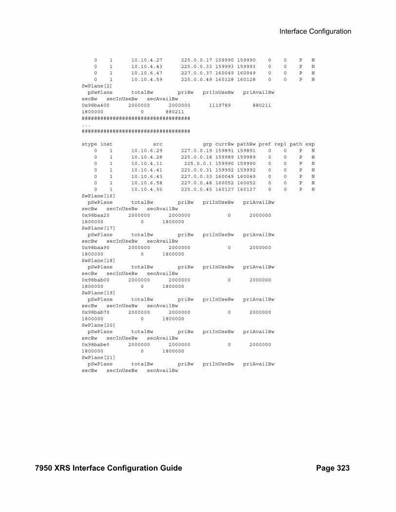
Interface Configuration
7950 XRS Interface Configuration Guide Page 323
0 1 10.10.4.27 225.0.0.17 159990 159990 0 0 P N 0 1 10.10.4.43 225.0.0.33 159993 159993 0 0 P N 0 1 10.10.6.47 227.0.0.37 160049 160049 0 0 P N 0 1 10.10.4.59 225.0.0.49 160128 160128 0 0 P NSwPlane[2] pSwPlane totalBw priBw priInUseBw priAvailBw secBw secInUseBw secAvailBw0x98ba400 2000000 2000000 1119789 880211 1800000 0 880211###################################...###################################
stype inst src grp currBw pathBw pref repl path exp 0 1 10.10.6.29 227.0.0.19 159891 159891 0 0 P N 0 1 10.10.4.28 225.0.0.18 159989 159989 0 0 P N 0 1 10.10.4.11 225.0.0.1 159990 159990 0 0 P N 0 1 10.10.4.41 225.0.0.31 159992 159992 0 0 P N 0 1 10.10.6.43 227.0.0.33 160049 160049 0 0 P N 0 1 10.10.6.58 227.0.0.48 160052 160052 0 0 P N 0 1 10.10.4.55 225.0.0.45 160127 160127 0 0 P NSwPlane[16] pSwPlane totalBw priBw priInUseBw priAvailBw secBw secInUseBw secAvailBw0x98baa20 2000000 2000000 0 2000000 1800000 0 1800000SwPlane[17] pSwPlane totalBw priBw priInUseBw priAvailBw secBw secInUseBw secAvailBw0x98baa90 2000000 2000000 0 2000000 1800000 0 1800000SwPlane[18] pSwPlane totalBw priBw priInUseBw priAvailBw secBw secInUseBw secAvailBw0x98bab00 2000000 2000000 0 2000000 1800000 0 1800000SwPlane[19] pSwPlane totalBw priBw priInUseBw priAvailBw secBw secInUseBw secAvailBw0x98bab70 2000000 2000000 0 2000000 1800000 0 1800000SwPlane[20] pSwPlane totalBw priBw priInUseBw priAvailBw secBw secInUseBw secAvailBw0x98babe0 2000000 2000000 0 2000000 1800000 0 1800000SwPlane[21] pSwPlane totalBw priBw priInUseBw priAvailBw secBw secInUseBw secAvailBw

Interfaces
Page 324 7950 XRS Interface Configuration Guide

Interface Configuration
7950 XRS Interface Configuration Guide Page 325
Show Commands
Hardware Show Commands
chassis
Syntax chassis chassis-id [environment] [power-supply] [ccm] chassis [detail]chassis [environment] [power-management] [ccm]
Context show
Description This command displays general chassis status information.
Parameters chassis-id — Displays chassis 1, 2, etc for router chassis.
environment — Displays chassis environmental status information.
Default Displays all chassis information.
power-supply — Displays chassis power supply status information.
Default Displays all chassis information.
ccm — Displays chassis control module information.
Output Chassis Output — The following table describes chassis output fields.
Label Description
Name The system name for the router.
Type Displays the router model number.
Chassis Topology The Chassis Topology is determined by the Active CPM when it boots up:- Standalone- Extended (XRS-40): The active CPM is running in a Master chassis.
Chassis role Chassis Roles are:- Standalone: the value for all non-XRS SR OS systems and for XRS-20 standalone systems- XRS-40 Master- XRS-40 Extension
Location The system location for the device.
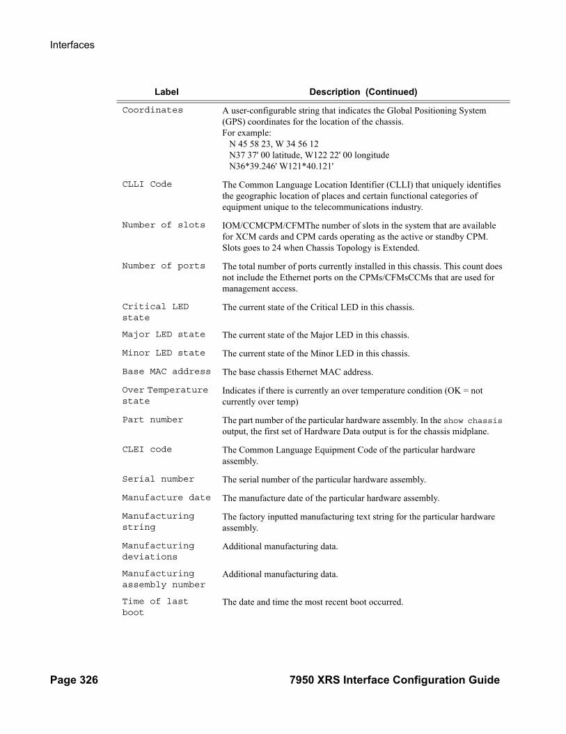
Interfaces
Page 326 7950 XRS Interface Configuration Guide
Coordinates A user-configurable string that indicates the Global Positioning System (GPS) coordinates for the location of the chassis.For example: N 45 58 23, W 34 56 12 N37 37' 00 latitude, W122 22' 00 longitude N36*39.246' W121*40.121'
CLLI Code The Common Language Location Identifier (CLLI) that uniquely identifies the geographic location of places and certain functional categories of equipment unique to the telecommunications industry.
Number of slots IOM/CCMCPM/CFMThe number of slots in the system that are available for XCM cards and CPM cards operating as the active or standby CPM. Slots goes to 24 when Chassis Topology is Extended.
Number of ports The total number of ports currently installed in this chassis. This count does not include the Ethernet ports on the CPMs/CFMsCCMs that are used for management access.
Critical LED state
The current state of the Critical LED in this chassis.
Major LED state The current state of the Major LED in this chassis.
Minor LED state The current state of the Minor LED in this chassis.
Base MAC address The base chassis Ethernet MAC address.
Over Temperature state
Indicates if there is currently an over temperature condition (OK = not currently over temp)
Part number The part number of the particular hardware assembly. In the show chassis output, the first set of Hardware Data output is for the chassis midplane.
CLEI code The Common Language Equipment Code of the particular hardware assembly.
Serial number The serial number of the particular hardware assembly.
Manufacture date The manufacture date of the particular hardware assembly.
Manufacturing string
The factory inputted manufacturing text string for the particular hardware assembly.
Manufacturing deviations
Additional manufacturing data.
Manufacturing assembly number
Additional manufacturing data.
Time of last boot
The date and time the most recent boot occurred.
Label Description (Continued)

Interface Configuration
7950 XRS Interface Configuration Guide Page 327
Sample Output
*A:myNode# show chassis===============================================================================System Information===============================================================================
Name : myNodeType : 7950 XRS-20Chassis Topology : Extended (XRS-40)
...
Number of slots : 24Oper number of slots : 24
...
Base MAC address : ac:9f:ff:00:00:00===============================================================================Chassis Summary===============================================================================
Current alarm state
Displays the alarm conditions for the specific board.
Number of fan trays
The total number of fan trays installed in this chassis.
Number of fans The total number of fans installed in this chassis.
Fan tray number The ID for each fan tray installed in the chassis
Speed Indicates the speed of the fans.
Status Current status of the particular hardware assembly.
Number of power supplies
The number of power supplies installed in the chassis.
Power supply number
The ID for each power supply installed in the chassis.
Power supply type
The basic type of the power supply.
Power supply model
The model of the power supply.
CCM Slot The identifier of the CCM (A or B).
Equipped Indicates if the CCM is detected as physically present.
Temperature The current temperature detected by the particular hardware assembly.
Temperature threshold
The temperature at which the particular hardware assembly considers an over temperature condition to exist.
Label Description (Continued)

Interfaces
Page 328 7950 XRS Interface Configuration Guide
Chassis Role Status-------------------------------------------------------------------------------1 XRS-40 Master Up2 XRS-40 Extension Up-------------------------------------------------------------------------------Total: 34===============================================================================
A:7950 XRS-20# show chassis detail===============================================================================System Information===============================================================================Name : 7950 XRS-20Type : 7950 XRS-20Chassis Topology : StandaloneLocation : (Not Specified)Coordinates : (Not Specified)CLLI code :Number of slots : 24Oper number of slots : 12Number of ports : 22Critical LED state : OffMajor LED state : RedMinor LED state : OffOver Temperature state : OKBase MAC address : ac:9f:ff:00:00:00===============================================================================Chassis 1 detail===============================================================================Chassis status : upChassis role : XRS-40 MasterHardware Data
Part number : Sim Part#CLEI code : Sim CLEISerial number : bksim3106Manufacture date : 01012003Manufacturing deviations : Sim MfgDeviation bksim3106Manufacturing assembly number : 01-2345-67Time of last boot : 2013/12/18 15:16:54Current alarm state : alarm active
-------------------------------------------------------------------------------Environment Information
Number of fan trays : 2Number of fans : 2
Fan tray number : 1Speed : half speedStatus : upHardware Data
Part number : Sim Part#CLEI code : Sim CLEISerial number : fan-1Manufacture date : 01012003Manufacturing deviations : Sim MfgDeviation fan-1Manufacturing assembly number : 01-2345-67Administrative state : upOperational state : up

Interface Configuration
7950 XRS Interface Configuration Guide Page 329
Time of last boot : 2013/12/18 14:16:58Current alarm state : alarm cleared
Hardware Resources (Power-Zone 1)Voltage
Minimum : 51.00 Volts (12/18/2013 15:17:00)Current : 51.00 VoltsPeak : 51.00 Volts (12/18/2013 15:17:00)
WattageMinimum : 561.00 Watts (12/18/2013 15:17:00)Current : 561.00 WattsPeak : 561.00 Watts (12/18/2013 15:17:00)Max Required : 900.00 Watts
AmperageMinimum : 11.00 Amps (12/18/2013 15:17:00)Current : 11.00 AmpsPeak : 11.00 Amps (12/18/2013 15:17:00)
Fan tray number : 2Speed : half speedStatus : upHardware Data
Part number : Sim Part#CLEI code : Sim CLEISerial number : fan-2Manufacture date : 01012003Manufacturing deviations : Sim MfgDeviation fan-2Manufacturing assembly number : 01-2345-67Administrative state : upOperational state : upTime of last boot : 2013/12/18 14:16:56Current alarm state : alarm cleared
Hardware Resources (Power-Zone 1)Voltage
Minimum : 52.00 Volts (12/18/2013 15:16:59)Current : 52.00 VoltsPeak : 52.00 Volts (12/18/2013 15:16:59)
WattageMinimum : 624.00 Watts (12/18/2013 15:16:59)Current : 624.00 WattsPeak : 624.00 Watts (12/18/2013 15:16:59)Max Required : 900.00 Watts
AmperageMinimum : 12.00 Amps (12/18/2013 15:16:59)Current : 12.00 AmpsPeak : 12.00 Amps (12/18/2013 15:16:59)
-------------------------------------------------------------------------------Power Management Information
Power Management Mode : basicPower Safety Level : 100%Power Safety Alert : 0 wattsNumber of PEQs : 12
PEQ number : 1PEQ Equipped Type : apeq-dc-2000PEQ Provisioned Type : (Not Specified)Power-Zone : 1Status : upInput Feed Status : power to all inputs

Interfaces
Page 330 7950 XRS Interface Configuration Guide
Hardware DataPart number : Sim Part#CLEI code : Sim CLEISerial number : peq-1Manufacture date : 01012003Manufacturing deviations : Sim MfgDeviation peq-1Manufacturing assembly number : 01-2345-67Administrative state : upOperational state : unprovisionedTime of last boot : 2013/12/18 14:16:53Current alarm state : alarm cleared
PEQ number : 2PEQ Equipped Type : apeq-dc-2000PEQ Provisioned Type : (Not Specified)Power-Zone : 1Status : upInput Feed Status : power to all inputsHardware Data
Part number : Sim Part#CLEI code : Sim CLEISerial number : peq-2Manufacture date : 01012003Manufacturing deviations : Sim MfgDeviation peq-2Manufacturing assembly number : 01-2345-67Administrative state : upOperational state : unprovisionedTime of last boot : 2013/12/18 14:16:52Current alarm state : alarm cleared
…PEQ number : 12
PEQ Equipped Type : apeq-dc-2000PEQ Provisioned Type : (Not Specified)Power-Zone : 1Status : upInput Feed Status : power to all inputsHardware Data
Part number : Sim Part#CLEI code : Sim CLEISerial number : peq-12Manufacture date : 01012003Manufacturing deviations : Sim MfgDeviation peq-12Manufacturing assembly number : 01-2345-67Administrative state : upOperational state : unprovisionedTime of last boot : 2013/12/18 14:16:42Current alarm state : alarm cleared
-------------------------------------------------------------------------------Chassis Control Module (CCM) Information
CCM Slot : AEquipped : yesHardware Data
Part number : Sim Part#CLEI code : Sim CLEISerial number : ccm-1Manufacture date : 01012003Manufacturing deviations : Sim MfgDeviation ccm-1Manufacturing assembly number : 01-2345-67
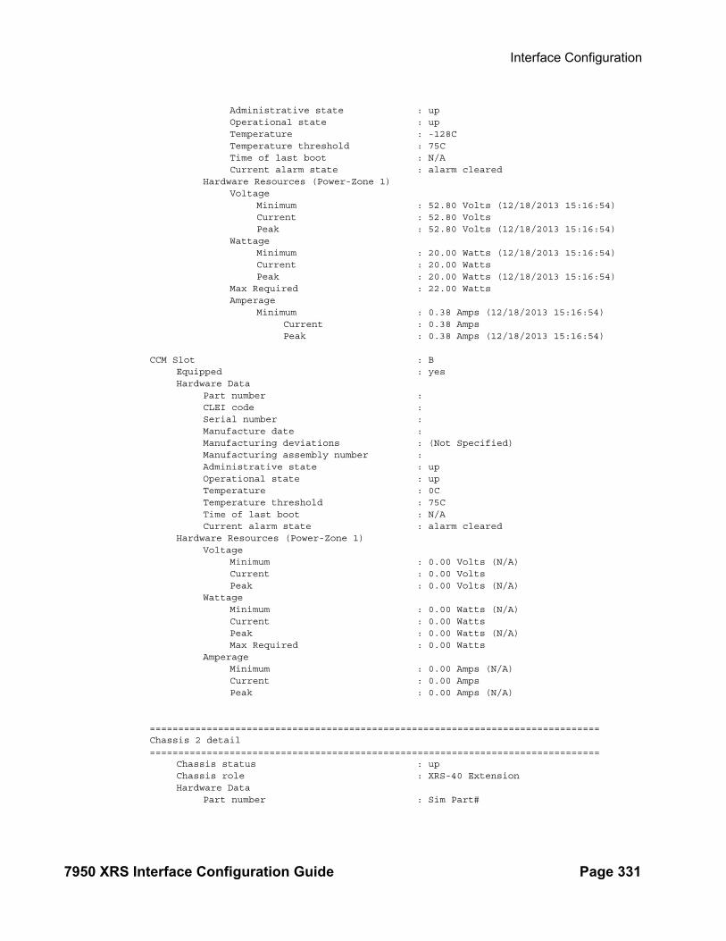
Interface Configuration
7950 XRS Interface Configuration Guide Page 331
Administrative state : upOperational state : upTemperature : -128CTemperature threshold : 75CTime of last boot : N/ACurrent alarm state : alarm cleared
Hardware Resources (Power-Zone 1)Voltage
Minimum : 52.80 Volts (12/18/2013 15:16:54)Current : 52.80 VoltsPeak : 52.80 Volts (12/18/2013 15:16:54)
WattageMinimum : 20.00 Watts (12/18/2013 15:16:54)Current : 20.00 WattsPeak : 20.00 Watts (12/18/2013 15:16:54)
Max Required : 22.00 WattsAmperage
Minimum : 0.38 Amps (12/18/2013 15:16:54)Current : 0.38 AmpsPeak : 0.38 Amps (12/18/2013 15:16:54)
CCM Slot : BEquipped : yesHardware Data
Part number :CLEI code :Serial number :Manufacture date :Manufacturing deviations : (Not Specified)Manufacturing assembly number :Administrative state : upOperational state : upTemperature : 0CTemperature threshold : 75CTime of last boot : N/ACurrent alarm state : alarm cleared
Hardware Resources (Power-Zone 1)Voltage
Minimum : 0.00 Volts (N/A)Current : 0.00 VoltsPeak : 0.00 Volts (N/A)
WattageMinimum : 0.00 Watts (N/A)Current : 0.00 WattsPeak : 0.00 Watts (N/A)Max Required : 0.00 Watts
AmperageMinimum : 0.00 Amps (N/A)Current : 0.00 AmpsPeak : 0.00 Amps (N/A)
===============================================================================Chassis 2 detail===============================================================================
Chassis status : upChassis role : XRS-40 ExtensionHardware Data
Part number : Sim Part#

Interfaces
Page 332 7950 XRS Interface Configuration Guide
CLEI code : Sim CLEISerial number : bksim3106Manufacture date : 01012003Manufacturing deviations : Sim MfgDeviation bksim3106Manufacturing assembly number : 01-2345-67Time of last boot : 2013/12/18 15:16:54Current alarm state : alarm active
-------------------------------------------------------------------------------Environment Information
Number of fan trays : 2Number of fans : 2
Fan tray number : 3Speed : unknownStatus : not equippedHardware Data
Part number :CLEI code :Serial number :Manufacture date :Manufacturing deviations : (Not Specified)Manufacturing assembly number :Administrative state : upOperational state : downTime of last boot : N/ACurrent alarm state : alarm cleared
Hardware Resources (Power-Zone 2)Voltage
Minimum : 0.00 Volts (N/A)Current : 0.00 VoltsPeak : 0.00 Volts (N/A)
WattageMinimum : 0.00 Watts (N/A)Current : 0.00 WattsPeak : 0.00 Watts (N/A)Max Required : 0.00 Watts
AmperageMinimum : 0.00 Amps (N/A)Current : 0.00 AmpsPeak : 0.00 Amps (N/A)
Fan tray number : 4Speed : unknownStatus : not equippedHardware Data
Part number :CLEI code :Serial number :Manufacture date :Manufacturing deviations : (Not Specified)Manufacturing assembly number :Administrative state : upOperational state : downTime of last boot : N/ACurrent alarm state : alarm cleared
Hardware Resources (Power-Zone 2)Voltage
Minimum : 0.00 Volts (N/A)

Interface Configuration
7950 XRS Interface Configuration Guide Page 333
Current : 0.00 VoltsPeak : 0.00 Volts (N/A)
WattageMinimum : 0.00 Watts (N/A)Current : 0.00 WattsPeak : 0.00 Watts (N/A)Max Required : 0.00 Watts
AmperageMinimum : 0.00 Amps (N/A)Current : 0.00 AmpsPeak : 0.00 Amps (N/A)
-------------------------------------------------------------------------------Power Management Information
Power Management Mode : basicPower Safety Level : 100%Power Safety Alert : 0 wattsNumber of PEQs : 12
PEQ number : 13PEQ Equipped Type : (Empty Slot)PEQ Provisioned Type : (Not Specified)Power-Zone : 2Status : not equippedInput Feed Status : not equippedHardware Data
Part number :CLEI code :Serial number :Manufacture date :Manufacturing deviations : (Not Specified)Manufacturing assembly number :Administrative state : upOperational state : unprovisionedTime of last boot : N/A
Current alarm state : alarm cleared
PEQ number : 14PEQ Equipped Type : (Empty Slot)PEQ Provisioned Type : (Not Specified)Power-Zone : 2Status : not equippedInput Feed Status : not equippedHardware Data
Part number :CLEI code :Serial number :Manufacture date :Manufacturing deviations : (Not Specified)Manufacturing assembly number :Administrative state : upOperational state : unprovisionedTime of last boot : N/ACurrent alarm state : alarm cleared
…PEQ number : 24
PEQ Equipped Type : (Empty Slot)PEQ Provisioned Type : (Not Specified)Power-Zone : 2

Interfaces
Page 334 7950 XRS Interface Configuration Guide
Status : not equippedInput Feed Status : not equippedHardware Data
Part number :CLEI code :Serial number :Manufacture date :Manufacturing deviations : (Not Specified)Manufacturing assembly number :Administrative state : upOperational state : unprovisionedTime of last boot : N/ACurrent alarm state : alarm cleared
-------------------------------------------------------------------------------Chassis Control Module (CCM) Information
CCM Slot : CEquipped : yesHardware Data
Part number :CLEI code :Serial number :Manufacture date :Manufacturing deviations : (Not Specified)Manufacturing assembly number :Administrative state : upOperational state : upTemperature : 0CTemperature threshold : 75CTime of last boot : N/ACurrent alarm state : alarm cleared
Hardware Resources (Power-Zone 2)Voltage
Minimum : 0.00 Volts (N/A)Current : 0.00 VoltsPeak : 0.00 Volts (N/A)
WattageMinimum : 0.00 Watts (N/A)Current : 0.00 WattsPeak : 0.00 Watts (N/A)Max Required : 0.00 Watts
AmperageMinimum : 0.00 Amps (N/A)Current : 0.00 AmpsPeak : 0.00 Amps (N/A)
CCM Slot : DEquipped : yesHardware Data
Part number :CLEI code :Serial number :Manufacture date :Manufacturing deviations : (Not Specified)Manufacturing assembly number :Administrative state : upOperational state : upTemperature : 0CTemperature threshold : 75C

Interface Configuration
7950 XRS Interface Configuration Guide Page 335
Time of last boot : N/ACurrent alarm state : alarm cleared
Hardware Resources (Power-Zone 2)Voltage
Minimum : 0.00 Volts (N/A)Current : 0.00 VoltsPeak : 0.00 Volts (N/A)
WattageMinimum : 0.00 Watts (N/A)Current : 0.00 WattsPeak : 0.00 Watts (N/A)Max Required : 0.00 Watts
AmperageMinimum : 0.00 Amps (N/A)Current : 0.00 AmpsPeak : 0.00 Amps (N/A)
===============================================================================
power-management
Syntax power-management [zone] [requirements | utilization] [detail]
Context show>chassis
Description This command displays power management requirement and utilization information.
Output Power-management Output Fields — he following table describes power-management output fields:
Label Description
Power Management Mode Specifies the configured power management mode: None, Basic, or Advanced.
Power Safety Level Specifies the configured Power Safety Level, which is a per-centage of the worst case power consumption level.
Power Safety Alert Specifies the configured power level in watts, which causes the system to raise an alarm if the available power level drops below a set level.
Power-Zone Specifies the chassis power zone.
Number of PEQs Specifies the total number of APEQs installed.
PEQ number: Specifies the APEQ to which the information is associated
PEQ Equipped Type Specifies the APEQ type installed.
PEQ Provisioned Type Specifies the APEQ type provisioned.
Status Specifies the APEQ status.
Input Feed Status Specifies the feed status.
Hardware Data:
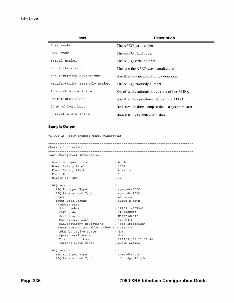
Interfaces
Page 336 7950 XRS Interface Configuration Guide
Sample Output
*A:Dut-A# show chassis power-management
===============================================================================Chassis Information===============================================================================Power Management Information
Power Management Mode : basic Power Safety Level : 100% Power Safety Alert : 0 watts Power-Zone : 1 Number of PEQs : 12 PEQ number : 1 PEQ Equipped Type : apeq-dc-2000 PEQ Provisioned Type : apeq-dc-2000 Status : shutdown Input Feed Status : input B down Hardware Data Part number : 3HE07114AARA01 CLEI code : IPUPAJHUAA Serial number : NS1250G0116 Manufacture date : 12202012 Manufacturing deviations : (Not Specified) Manufacturing assembly number : 8205320107 Administrative state : down Operational state : down Time of last boot : 2014/01/07 11:01:44 Current alarm state : alarm active PEQ number : 2 PEQ Equipped Type : apeq-dc-2000 PEQ Provisioned Type : (Not Specified)
Part number The APEQ part number.
CLEI code The APEQ CLEI code.
Serial number The APEQ serial number.
Manufacture date The date the APEQ was manufactured
Manufacturing deviations Specifies any manufacturing deviations.
Manufacturing assembly number The APEQ assembly number.
Administrative state Specifies the administrative state of the APEQ.
Operational state Specifies the operational state of the APEQ.
Time of last boot Indicates the time stamp of the last system restart.
Current alarm state Indicates the current alarm state.
Label Description

Interface Configuration
7950 XRS Interface Configuration Guide Page 337
Status : up Input Feed Status : input B down Hardware Data Part number : 3HE07114AARA01 CLEI code : IPUPAJHUAA Serial number : NS1249G0022 Manufacture date : 12202012 Manufacturing deviations : (Not Specified) Manufacturing assembly number : 8205320107 Administrative state : up Operational state : unprovisioned Time of last boot : 2014/01/07 11:01:44 Current alarm state : alarm active PEQ number : 3 PEQ Equipped Type : apeq-dc-2000 PEQ Provisioned Type : apeq-dc-2000 Status : up Input Feed Status : input B down Hardware Data Part number : 3HE07114AARA01 CLEI code : IPUPAJHUAA Serial number : NS1250G0141 Manufacture date : 12202012 Manufacturing deviations : (Not Specified) Manufacturing assembly number : 8205320107 Administrative state : up Operational state : up Time of last boot : 2014/01/07 11:01:44 Current alarm state : alarm active PEQ number : 4 PEQ Equipped Type : apeq-dc-2000 PEQ Provisioned Type : apeq-dc-2000 Status : up Input Feed Status : input B down Hardware Data Part number : 3HE07114AARA01 CLEI code : IPUPAJHUAA Serial number : NS1249G0201 Manufacture date : 12202012 Manufacturing deviations : (Not Specified) Manufacturing assembly number : 8205320107 Administrative state : up Operational state : up Time of last boot : 2014/01/07 11:01:44 Current alarm state : alarm active PEQ number : 5 PEQ Equipped Type : apeq-dc-2000 PEQ Provisioned Type : apeq-dc-2000 Status : up Input Feed Status : input B down Hardware Data Part number : 3HE07114AARA01 CLEI code : IPUPAJHUAA Serial number : NS1250G0123 Manufacture date : 12202012 Manufacturing deviations : (Not Specified)
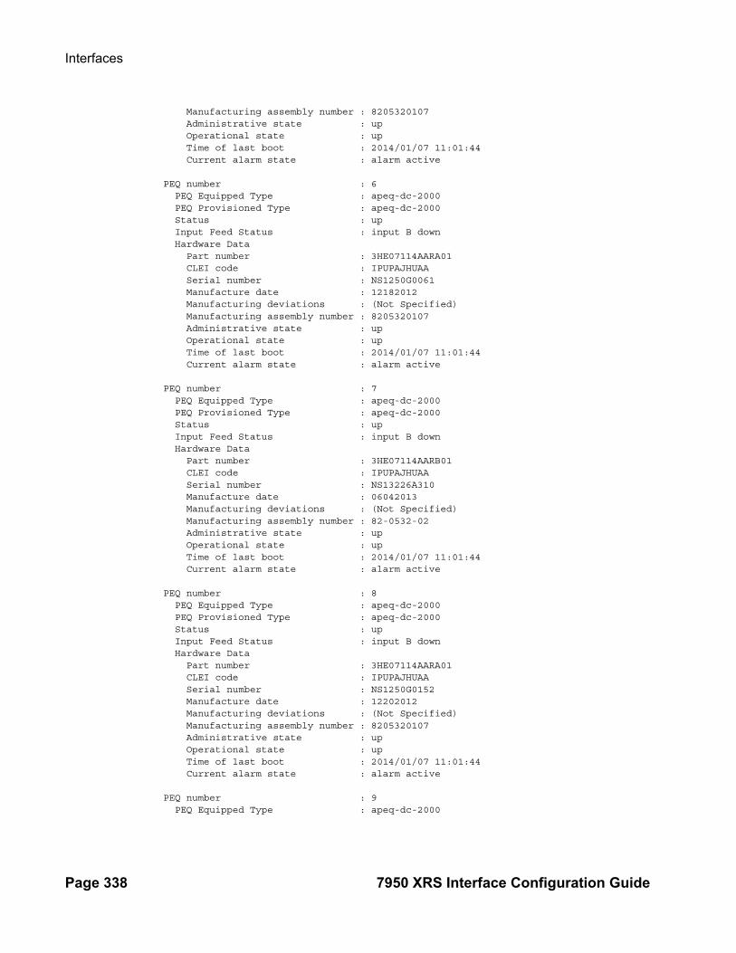
Interfaces
Page 338 7950 XRS Interface Configuration Guide
Manufacturing assembly number : 8205320107 Administrative state : up Operational state : up Time of last boot : 2014/01/07 11:01:44 Current alarm state : alarm active PEQ number : 6 PEQ Equipped Type : apeq-dc-2000 PEQ Provisioned Type : apeq-dc-2000 Status : up Input Feed Status : input B down Hardware Data Part number : 3HE07114AARA01 CLEI code : IPUPAJHUAA Serial number : NS1250G0061 Manufacture date : 12182012 Manufacturing deviations : (Not Specified) Manufacturing assembly number : 8205320107 Administrative state : up Operational state : up Time of last boot : 2014/01/07 11:01:44 Current alarm state : alarm active PEQ number : 7 PEQ Equipped Type : apeq-dc-2000 PEQ Provisioned Type : apeq-dc-2000 Status : up Input Feed Status : input B down Hardware Data Part number : 3HE07114AARB01 CLEI code : IPUPAJHUAA Serial number : NS13226A310 Manufacture date : 06042013 Manufacturing deviations : (Not Specified) Manufacturing assembly number : 82-0532-02 Administrative state : up Operational state : up Time of last boot : 2014/01/07 11:01:44 Current alarm state : alarm active PEQ number : 8 PEQ Equipped Type : apeq-dc-2000 PEQ Provisioned Type : apeq-dc-2000 Status : up Input Feed Status : input B down Hardware Data Part number : 3HE07114AARA01 CLEI code : IPUPAJHUAA Serial number : NS1250G0152 Manufacture date : 12202012 Manufacturing deviations : (Not Specified) Manufacturing assembly number : 8205320107 Administrative state : up Operational state : up Time of last boot : 2014/01/07 11:01:44 Current alarm state : alarm active PEQ number : 9 PEQ Equipped Type : apeq-dc-2000
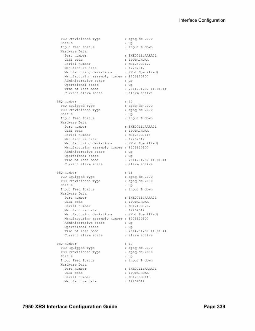
Interface Configuration
7950 XRS Interface Configuration Guide Page 339
PEQ Provisioned Type : apeq-dc-2000 Status : up Input Feed Status : input B down Hardware Data Part number : 3HE07114AARA01 CLEI code : IPUPAJHUAA Serial number : NS1250G0122 Manufacture date : 12202012 Manufacturing deviations : (Not Specified) Manufacturing assembly number : 8205320107 Administrative state : up Operational state : up Time of last boot : 2014/01/07 11:01:44 Current alarm state : alarm active PEQ number : 10 PEQ Equipped Type : apeq-dc-2000 PEQ Provisioned Type : apeq-dc-2000 Status : up Input Feed Status : input B down Hardware Data Part number : 3HE07114AARA01 CLEI code : IPUPAJHUAA Serial number : NS1250G0146 Manufacture date : 12202012 Manufacturing deviations : (Not Specified) Manufacturing assembly number : 8205320107 Administrative state : up Operational state : up Time of last boot : 2014/01/07 11:01:44 Current alarm state : alarm active PEQ number : 11 PEQ Equipped Type : apeq-dc-2000 PEQ Provisioned Type : apeq-dc-2000 Status : up Input Feed Status : input B down Hardware Data Part number : 3HE07114AARA01 CLEI code : IPUPAJHUAA Serial number : NS1249G0202 Manufacture date : 12202012 Manufacturing deviations : (Not Specified) Manufacturing assembly number : 8205320107 Administrative state : up Operational state : up Time of last boot : 2014/01/07 11:01:44 Current alarm state : alarm active PEQ number : 12 PEQ Equipped Type : apeq-dc-2000 PEQ Provisioned Type : apeq-dc-2000 Status : up Input Feed Status : input B down Hardware Data Part number : 3HE07114AARA01 CLEI code : IPUPAJHUAA Serial number : NS1250G0115 Manufacture date : 12202012

Interfaces
Page 340 7950 XRS Interface Configuration Guide
Manufacturing deviations : (Not Specified) Manufacturing assembly number : 8205320107 Administrative state : up Operational state : up Time of last boot : 2014/01/07 11:01:44 Current alarm state : alarm active===============================================================================
Output Power-management requirements Output Fields — he following table describes power-management requirements output fields:
Sample Output
*A:Dut-A# show chassis power-management requirements
===============================================================================Chassis Power Requirements=============================================================================== SUPPLY REQUIREMENTSPower Capacity : 22000.00 Watts Fan : 1800.00 Watts ( 8%)Safety Level : 13203.00 Watts (100%) IO Module : 1395.00 Watts ( 6%)Alert Level : 0.00 Watts CPM Module : 408.00 Watts ( 2%) Fabric Module : 1600.00 Watts ( 7%) MDA Module : 7956.00 Watts ( 36%) CCM Module : 44.00 Watts ( 0%) Total Required: 13203.00 Watts ( 60%)===============================================================================
Label Description
SUPPLY
Power Capacity Indicates the total amount of power available to the chassis.
Safety Level Specifies the configured Power Safety Level, which is a percentage of the worst case power consumption level.
Alert Level Specifies the configured power level in watts, which causes the system to raise an alarm if the available power level drops below a set level.
REQUIREMENTS
Fan Specifies the amount of power required for each fan tray.
IO Module Specifies the amount of power required for each IO Module.
CPM Module Specifies the amount of power required for each CPM.
Fabric Module Specifies the amount of power required for each SFM.
MDA Module Specifies the amount of power required for each line card.
Total Required Specifies the total amount of power required for all system elements.
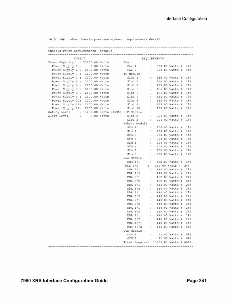
Interface Configuration
7950 XRS Interface Configuration Guide Page 341
*A:Dut-A# show chassis power-management requirements detail
===============================================================================Chassis Power Requirements (detail)=============================================================================== SUPPLY REQUIREMENTSPower Capacity : 22000.00 Watts Fan Power Supply 1 : 0.00 Watts Fan 1 : 900.00 Watts ( 4%) Power Supply 2 : 2000.00 Watts Fan 2 : 900.00 Watts ( 4%) Power Supply 3 : 2000.00 Watts IO Module Power Supply 4 : 2000.00 Watts Slot 1 : 155.00 Watts ( 1%) Power Supply 5 : 2000.00 Watts Slot 2 : 155.00 Watts ( 1%) Power Supply 6 : 2000.00 Watts Slot 3 : 155.00 Watts ( 1%) Power Supply 7 : 2000.00 Watts Slot 5 : 155.00 Watts ( 1%) Power Supply 8 : 2000.00 Watts Slot 6 : 155.00 Watts ( 1%) Power Supply 9 : 2000.00 Watts Slot 7 : 155.00 Watts ( 1%) Power Supply 10: 2000.00 Watts Slot 8 : 155.00 Watts ( 1%) Power Supply 11: 2000.00 Watts Slot 9 : 155.00 Watts ( 1%) Power Supply 12: 2000.00 Watts Slot 10 : 155.00 Watts ( 1%)Safety Level : 13203.00 Watts (100%) CPM Module Alert Level : 0.00 Watts Slot A : 204.00 Watts ( 1%) Slot B : 204.00 Watts ( 1%) Fabric Module Sfm 1 : 200.00 Watts ( 1%) Sfm 2 : 200.00 Watts ( 1%) Sfm 3 : 200.00 Watts ( 1%) Sfm 4 : 200.00 Watts ( 1%) Sfm 5 : 200.00 Watts ( 1%) Sfm 6 : 200.00 Watts ( 1%) Sfm 7 : 200.00 Watts ( 1%) Sfm 8 : 200.00 Watts ( 1%) MDA Module MDA 1/1 : 452.00 Watts ( 2%) MDA 1/2 : 440.00 Watts ( 2%) MDA 2/1 : 440.00 Watts ( 2%) MDA 2/2 : 440.00 Watts ( 2%) MDA 3/1 : 452.00 Watts ( 2%) MDA 3/2 : 452.00 Watts ( 2%) MDA 5/1 : 440.00 Watts ( 2%) MDA 5/2 : 440.00 Watts ( 2%) MDA 6/1 : 440.00 Watts ( 2%) MDA 6/2 : 440.00 Watts ( 2%) MDA 7/1 : 440.00 Watts ( 2%) MDA 7/2 : 440.00 Watts ( 2%) MDA 8/1 : 440.00 Watts ( 2%) MDA 8/2 : 440.00 Watts ( 2%) MDA 9/1 : 440.00 Watts ( 2%) MDA 9/2 : 440.00 Watts ( 2%) MDA 10/1 : 440.00 Watts ( 2%) MDA 10/2 : 440.00 Watts ( 2%) CCM Module CCM 1 : 22.00 Watts ( 0%) CCM 2 : 22.00 Watts ( 0%) Total Required: 13203.00 Watts ( 60%)===============================================================================

Interfaces
Page 342 7950 XRS Interface Configuration Guide
Output Power-management utilization Output Fields — he following table describes power-management utilization output fields:
Sample Output
*A:Dut-A# show chassis power-management utilization
===============================================================================Chassis Power Utilization=============================================================================== SUPPLY PEAK DEMAND Power Capacity : 22000.00 Watts Fan : 695.00 Watts ( 3%)Safety Level : 13203.00 Watts (100%) IO Module : 7163.09 Watts ( 33%)Alert Level : 0.00 Watts CPM Module : 392.86 Watts ( 2%) Fabric Module : 1622.25 Watts ( 7%) MDA Module : 6023.07 Watts ( 27%)+ CCM Module : 50.82 Watts ( 0%) Peak Util. : 9924.02 Watts ( 45%) CURRENT DEMAND Current Util. : 9623.01 Watts ( 44%)===============================================================================+ Power utilization of device already included in IO Module value
*A:Dut-A# show chassis power-management utilization detail
===============================================================================Chassis Power Utilization (detail)===============================================================================
Label Description
SUPPLY
Power Capacity Indicates the total amount of power available to the chassis.
Safety Level Specifies the configured Power Safety Level, which is a percentage of the worst case power consumption level.
Alert Level Specifies the configured power level in watts, which causes the system to raise an alarm if the available power level drops below a set level.
DEMAND
Fan Specifies the amount of power utilized for the fan tray indicated.
IO Module Specifies the amount of power utilized for the IO Module indicated.
CPM Module Specifies the amount of power utilized for the CPM indicated.
Fabric Module Specifies the amount of power utilized for the SFM indicated.
MDA Module Specifies the amount of power utilized for the line card indicated.
Current Util. Specifies the total amount of power utilized for all system elements.
Peak Util. Specifies peak utilization starting from boot up.
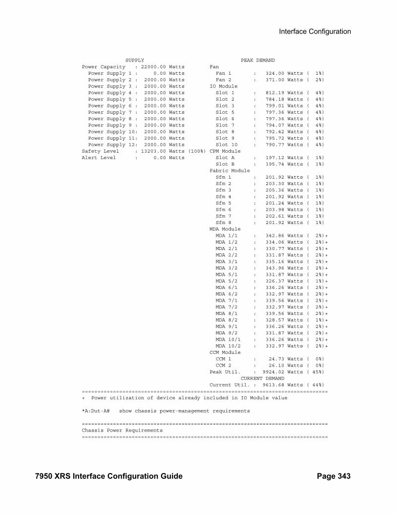
Interface Configuration
7950 XRS Interface Configuration Guide Page 343
SUPPLY PEAK DEMAND Power Capacity : 22000.00 Watts Fan Power Supply 1 : 0.00 Watts Fan 1 : 324.00 Watts ( 1%) Power Supply 2 : 2000.00 Watts Fan 2 : 371.00 Watts ( 2%) Power Supply 3 : 2000.00 Watts IO Module Power Supply 4 : 2000.00 Watts Slot 1 : 812.19 Watts ( 4%) Power Supply 5 : 2000.00 Watts Slot 2 : 784.18 Watts ( 4%) Power Supply 6 : 2000.00 Watts Slot 3 : 799.01 Watts ( 4%) Power Supply 7 : 2000.00 Watts Slot 5 : 797.36 Watts ( 4%) Power Supply 8 : 2000.00 Watts Slot 6 : 797.36 Watts ( 4%) Power Supply 9 : 2000.00 Watts Slot 7 : 794.07 Watts ( 4%) Power Supply 10: 2000.00 Watts Slot 8 : 792.42 Watts ( 4%) Power Supply 11: 2000.00 Watts Slot 9 : 795.72 Watts ( 4%) Power Supply 12: 2000.00 Watts Slot 10 : 790.77 Watts ( 4%)Safety Level : 13203.00 Watts (100%) CPM Module Alert Level : 0.00 Watts Slot A : 197.12 Watts ( 1%) Slot B : 195.74 Watts ( 1%) Fabric Module Sfm 1 : 201.92 Watts ( 1%) Sfm 2 : 203.30 Watts ( 1%) Sfm 3 : 205.36 Watts ( 1%) Sfm 4 : 201.92 Watts ( 1%) Sfm 5 : 201.24 Watts ( 1%) Sfm 6 : 203.98 Watts ( 1%) Sfm 7 : 202.61 Watts ( 1%) Sfm 8 : 201.92 Watts ( 1%) MDA Module MDA 1/1 : 342.86 Watts ( 2%)+ MDA 1/2 : 334.06 Watts ( 2%)+ MDA 2/1 : 330.77 Watts ( 2%)+ MDA 2/2 : 331.87 Watts ( 2%)+ MDA 3/1 : 335.16 Watts ( 2%)+ MDA 3/2 : 343.96 Watts ( 2%)+ MDA 5/1 : 331.87 Watts ( 2%)+ MDA 5/2 : 326.37 Watts ( 1%)+ MDA 6/1 : 336.26 Watts ( 2%)+ MDA 6/2 : 332.97 Watts ( 2%)+ MDA 7/1 : 339.56 Watts ( 2%)+ MDA 7/2 : 332.97 Watts ( 2%)+ MDA 8/1 : 339.56 Watts ( 2%)+ MDA 8/2 : 328.57 Watts ( 1%)+ MDA 9/1 : 336.26 Watts ( 2%)+ MDA 9/2 : 331.87 Watts ( 2%)+ MDA 10/1 : 336.26 Watts ( 2%)+ MDA 10/2 : 332.97 Watts ( 2%)+ CCM Module CCM 1 : 24.73 Watts ( 0%) CCM 2 : 26.10 Watts ( 0%) Peak Util. : 9924.02 Watts ( 45%) CURRENT DEMAND Current Util. : 9613.68 Watts ( 44%)===============================================================================+ Power utilization of device already included in IO Module value
*A:Dut-A# show chassis power-management requirements
===============================================================================Chassis Power Requirements===============================================================================

Interfaces
Page 344 7950 XRS Interface Configuration Guide
SUPPLY REQUIREMENTSPower Capacity : 22000.00 Watts Fan : 1800.00 Watts ( 8%)Safety Level : 13203.00 Watts (100%) IO Module : 1395.00 Watts ( 6%)Alert Level : 0.00 Watts CPM Module : 408.00 Watts ( 2%) Fabric Module : 1600.00 Watts ( 7%) MDA Module : 7956.00 Watts ( 36%) CCM Module : 44.00 Watts ( 0%) Total Required: 13203.00 Watts ( 60%)===============================================================================
card
Syntax card [slot-number] [detail]card statecardslot-number [card] fp [1..2] ingress queue-group queue-group-name instance [1..65535] mode {access|network} [statistics]
Context show
Description This command displays (XCM) card information.
If no command line parameters are specified, a card summary for all cards is displayed.
Parameters slot-number — Displays information for the specified card slot.
Default Displays all cards.
Values XCM slots are numbered from 1 - 10CPM slots are A, B, C, D (upper or lowercase)SFM slots are not addressed as cards. See show sfm command.
state — Displays provisioned and equipped card and MDA information.
detail — Displays detailed card information.
Default Displays summary information only.
Output Show Card Output — The following table describes show card output fields.
Label Description
Slot The slot number of the card in the chassis.
Provisioned type The card type that is configured for the slot.Note: CPMs C and D will not show up in the summary unless the Chassis Topology is Extended (XRS-40).
Equipped type The card type that is actually populated in the slot.Note: CPMs C and D will not show up in the summary unless the Chassis Topology is Extended (XRS-40).
Admin State Up — The card is administratively up.
Down — The card is administratively down (e.g., shutdown)
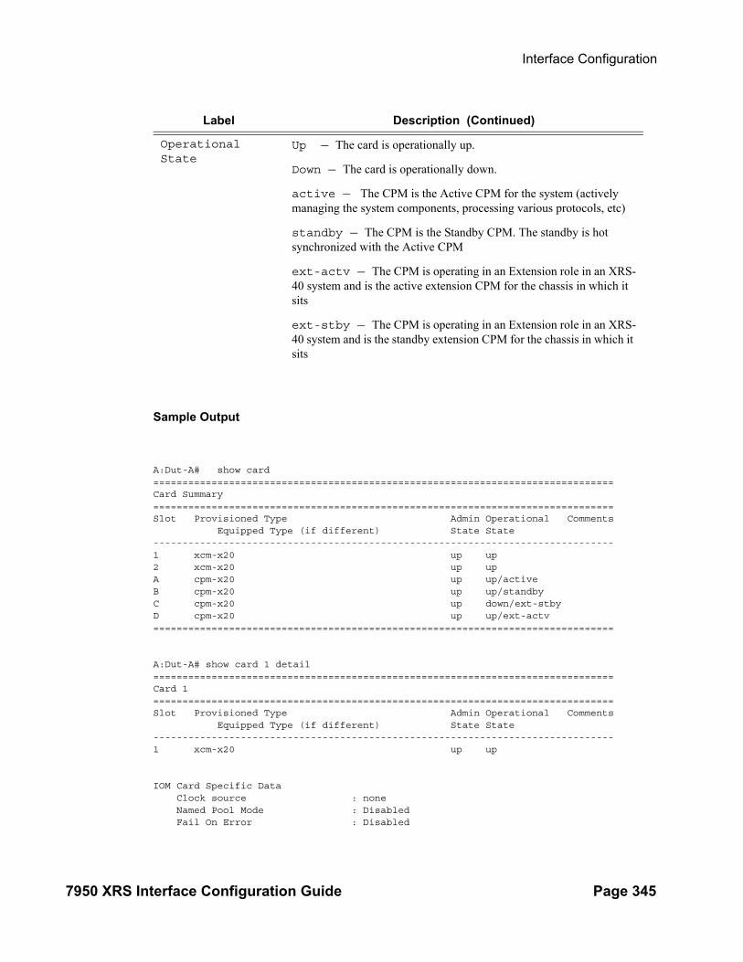
Interface Configuration
7950 XRS Interface Configuration Guide Page 345
Sample Output
A:Dut-A# show card ===============================================================================Card Summary===============================================================================Slot Provisioned Type Admin Operational Comments Equipped Type (if different) State State -------------------------------------------------------------------------------1 xcm-x20 up up 2 xcm-x20 up up A cpm-x20 up up/active B cpm-x20 up up/standby C cpm-x20 up down/ext-stby D cpm-x20 up up/ext-actv ===============================================================================
A:Dut-A# show card 1 detail ===============================================================================Card 1===============================================================================Slot Provisioned Type Admin Operational Comments Equipped Type (if different) State State -------------------------------------------------------------------------------1 xcm-x20 up up
IOM Card Specific Data Clock source : none Named Pool Mode : Disabled Fail On Error : Disabled
Operational State
Up — The card is operationally up.
Down — The card is operationally down.
active — The CPM is the Active CPM for the system (actively managing the system components, processing various protocols, etc)
standby — The CPM is the Standby CPM. The standby is hot synchronized with the Active CPM
ext-actv — The CPM is operating in an Extension role in an XRS-40 system and is the active extension CPM for the chassis in which it sits
ext-stby — The CPM is operating in an Extension role in an XRS-40 system and is the standby extension CPM for the chassis in which it sits
Label Description (Continued)
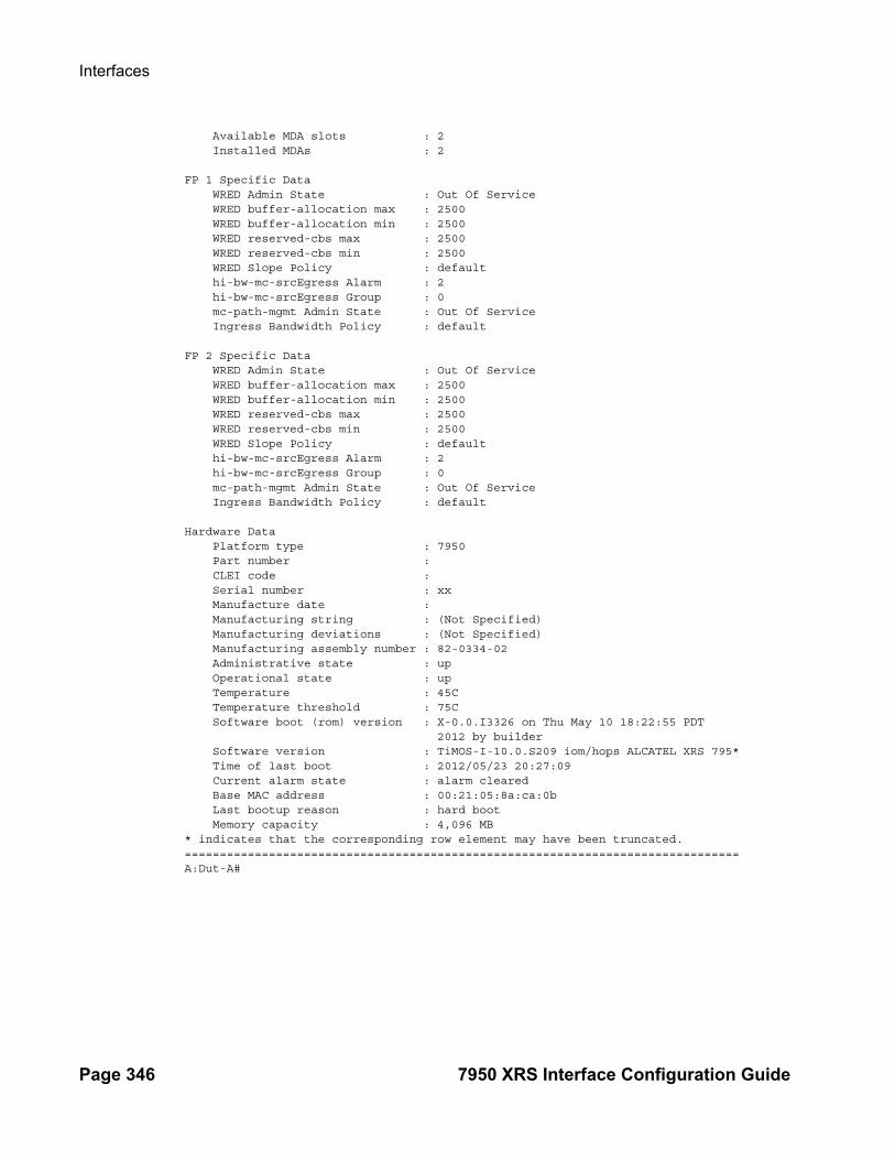
Interfaces
Page 346 7950 XRS Interface Configuration Guide
Available MDA slots : 2 Installed MDAs : 2
FP 1 Specific Data WRED Admin State : Out Of Service WRED buffer-allocation max : 2500 WRED buffer-allocation min : 2500 WRED reserved-cbs max : 2500 WRED reserved-cbs min : 2500 WRED Slope Policy : default hi-bw-mc-srcEgress Alarm : 2 hi-bw-mc-srcEgress Group : 0 mc-path-mgmt Admin State : Out Of Service Ingress Bandwidth Policy : default
FP 2 Specific Data WRED Admin State : Out Of Service WRED buffer-allocation max : 2500 WRED buffer-allocation min : 2500 WRED reserved-cbs max : 2500 WRED reserved-cbs min : 2500 WRED Slope Policy : default hi-bw-mc-srcEgress Alarm : 2 hi-bw-mc-srcEgress Group : 0 mc-path-mgmt Admin State : Out Of Service Ingress Bandwidth Policy : default
Hardware Data Platform type : 7950 Part number : CLEI code : Serial number : xx Manufacture date : Manufacturing string : (Not Specified) Manufacturing deviations : (Not Specified) Manufacturing assembly number : 82-0334-02 Administrative state : up Operational state : up Temperature : 45C Temperature threshold : 75C Software boot (rom) version : X-0.0.I3326 on Thu May 10 18:22:55 PDT 2012 by builder Software version : TiMOS-I-10.0.S209 iom/hops ALCATEL XRS 795* Time of last boot : 2012/05/23 20:27:09 Current alarm state : alarm cleared Base MAC address : 00:21:05:8a:ca:0b Last bootup reason : hard boot Memory capacity : 4,096 MB* indicates that the corresponding row element may have been truncated.===============================================================================A:Dut-A#

Interface Configuration
7950 XRS Interface Configuration Guide Page 347
Show Card State Output — The following table describes show card state output fields.
Sample Output
A:Dut-A# show card state ===============================================================================Card State===============================================================================Slot/ Provisioned Type Admin Operational Num Num CommentsId Equipped Type (if different) State State Ports MDA -------------------------------------------------------------------------------1 xcm-x20 up up 2 1/1 cx20-10g-sfp up up 20 1/2 cx20-10g-sfp up up 20 2 xcm-x20 up up 2 2/1 cx20-10g-sfp up up 20 A cpm-x20 up up ActiveB cpm-x20 up up Standby===============================================================================
Show Card Detail Output — The following table describes detailed card output fields.
Label Description
Slot/MDA The slot number of the card in the chassis.
Provisioned Type The card type that is configured for the slot.
Equipped Type The card type that is actually populated in the slot.
Admin State Up — The card is administratively up.
Down — The card is administratively down.
Operational State
Up — The card is operationally up.
provisioned — There is no card in the slot but it has been pre-configured.
Num Ports The number of ports available on the MDA.
Num MDA The number of MDAs installed.
Comments Indicates whether the SF/CPM is the active or standby.
Label Description
Clock source Source of clock for the IOM. Note: Currently this parameter always displays 'none'
Available MDA slots
The number of MDA slots available on the IOM.
Installed MDAs The number of MDAs installed on the IOM
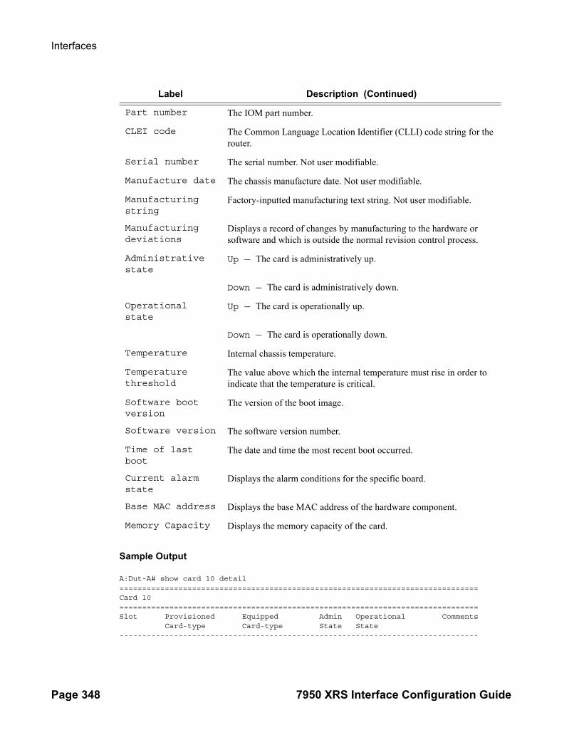
Interfaces
Page 348 7950 XRS Interface Configuration Guide
Sample Output
A:Dut-A# show card 10 detail ===============================================================================Card 10===============================================================================Slot Provisioned Equipped Admin Operational Comments Card-type Card-type State State -------------------------------------------------------------------------------
Part number The IOM part number.
CLEI code The Common Language Location Identifier (CLLI) code string for the router.
Serial number The serial number. Not user modifiable.
Manufacture date The chassis manufacture date. Not user modifiable.
Manufacturing string
Factory-inputted manufacturing text string. Not user modifiable.
Manufacturing deviations
Displays a record of changes by manufacturing to the hardware or software and which is outside the normal revision control process.
Administrative state
Up — The card is administratively up.
Down — The card is administratively down.
Operational state
Up — The card is operationally up.
Down — The card is operationally down.
Temperature Internal chassis temperature.
Temperature threshold
The value above which the internal temperature must rise in order to indicate that the temperature is critical.
Software boot version
The version of the boot image.
Software version The software version number.
Time of last boot
The date and time the most recent boot occurred.
Current alarm state
Displays the alarm conditions for the specific board.
Base MAC address Displays the base MAC address of the hardware component.
Memory Capacity Displays the memory capacity of the card.
Label Description (Continued)

Interface Configuration
7950 XRS Interface Configuration Guide Page 349
10 iom3-xp iom3-xp up up
IOM Card Specific Data Clock source : none Named Pool Mode : Disabled Fail On Error : Disabled Available MDA slots : 2 Installed MDAs : 1
FP 1 Specific Data WRED Admin State : Out Of Service WRED buffer-allocation max : 2500 WRED buffer-allocation min : 2500 WRED reserved-cbs max : 2500 WRED reserved-cbs min : 2500 WRED Slope Policy : default hi-bw-mc-srcEgress Alarm : 2 hi-bw-mc-srcEgress Group : 0 mc-path-mgmt Admin State : Out Of Service Ingress Bandwidth Policy : default
Hardware Data Platform type : 7750 Part number : 3HE03619AAAK01 CLEI code : IPU3AC9EAA Serial number : NS1112F0955 Manufacture date : 03182011 Manufacturing string : Manufacturing deviations : Manufacturing assembly number : 82-0107-09 Administrative state : up Operational state : up Temperature : 50C Temperature threshold : 75C Software boot (rom) version : X-0.0.I3122 on Mon Oct 17 18:16:02 PDT 2011* Software version : TiMOS-I-8.0.B1-250 iom/hops ALCATEL SR 7750* Time of last boot : 2011/11/15 08:44:52 Current alarm state : alarm cleared Base MAC address : 8c:90:d3:a4:fb:33 Last bootup reason : hard boot Memory capacity : 2,048 MB A:Dut-A# show card 1 detail ===============================================================================Card 1===============================================================================Slot Provisioned Type Admin Operational Comments Equipped Type (if different) State State -------------------------------------------------------------------------------1 xcm-x20 up up
IOM Card Specific Data Clock source : none Named Pool Mode : Disabled Fail On Error : Disabled Available MDA slots : 2 Installed MDAs : 2

Interfaces
Page 350 7950 XRS Interface Configuration Guide
FP 1 Specific Data WRED Admin State : Out Of Service WRED buffer-allocation max : 2500 WRED buffer-allocation min : 2500 WRED reserved-cbs max : 2500 WRED reserved-cbs min : 2500 WRED Slope Policy : default hi-bw-mc-srcEgress Alarm : 2 hi-bw-mc-srcEgress Group : 0 mc-path-mgmt Admin State : Out Of Service Ingress Bandwidth Policy : default
FP 2 Specific Data WRED Admin State : Out Of Service WRED buffer-allocation max : 2500 WRED buffer-allocation min : 2500 WRED reserved-cbs max : 2500 WRED reserved-cbs min : 2500 WRED Slope Policy : default hi-bw-mc-srcEgress Alarm : 2 hi-bw-mc-srcEgress Group : 0 mc-path-mgmt Admin State : Out Of Service Ingress Bandwidth Policy : default
Hardware Data Platform type : 7950 Part number : CLEI code : Serial number : xx Manufacture date : Manufacturing string : (Not Specified) Manufacturing deviations : (Not Specified) Manufacturing assembly number : 82-0334-02 Administrative state : up Operational state : up Temperature : 45C Temperature threshold : 75C Software boot (rom) version : X-0.0.I3326 on Thu May 10 18:22:55 PDT 2012 by builder Software version : TiMOS-I-10.0.S209 iom/hops ALCATEL XRS 795* Time of last boot : 2012/05/23 20:27:09 Current alarm state : alarm cleared Base MAC address : 00:21:05:8a:ca:0b Last bootup reason : hard boot Memory capacity : 4,096 MB* indicates that the corresponding row element may have been truncated.===============================================================================A:Dut-A#

Interface Configuration
7950 XRS Interface Configuration Guide Page 351
CPM Output — The following table describes the output fields for a CPM card.
Label Description
Slot The slot of the card in the chassis.
Card Provisioned The SF/CPM type that is configured for the slot.Note: CPMs C and D will not show up in the summary unless the Chassis Topology is Extended (XRS-40).
Card Equipped The SF/CPM type that is actually populated in the slot.Note: CPMs C and D will not show up in the summary unless the Chassis Topology is Extended (XRS-40).
Admin State Up — The SF/CPM is administratively up.
Down — The SF/CPM is administratively down.
Operational State
Up — The SF/CPM is operationally up.
Down — The SF/CPM is operationally down.
Inter chassis cpm interconnect
Up — The CPM is operationally up.
Down — The CPM is operationally down.
BOF last modified The date and time of the most recent BOF modification.
Config file ver-sion
The configuration file version.
Config file last modified
The date and time of the most recent config file modification.
Config file last modified
The date and time of the most recent config file modification.
Config file last saved
The date and time of the most recent config file save.
CPM card status active — The card is acting as the primary (active) CPM in a redundant system.standby — The card is acting as the standby (secondary) CPM in a redundant system.
Administrative state
Up — The CPM is administratively up.Down — The CPM is administratively down.
Operational state
Up — The CPM is operationally up.Down — The CPM is operationally down.

Interfaces
Page 352 7950 XRS Interface Configuration Guide
Sample Output
B:NS082761964# show card B detail ===============================================================================Card B===============================================================================
Serial number The compact flash part number. Not user modifiable.
Firmware revi-sion
The firmware version. Not user modifiable.
Model number The compact flash model number. Not user modifiable.
Size The amount of space available on the compact flash card.
Free space The amount of space remaining on the compact flash card.
Part number The SF/CPM part number.
CLEI code The code used to identify the router.
Serial number The SF/CPM part number. Not user modifiable.
Manufacture date The chassis manufacture date. Not user modifiable.
Manufacturing string
Factory-inputted manufacturing text string. Not user modifiable.
Administrative state
Up — The card is administratively up.Down — The card is administratively down.
Operational state
Up — The card is operationally up.
Down — The card is operationally down.
Time of last boot
The date and time the most recent boot occurred.
Current alarm state
Displays the alarm conditions for the specific board.
Status Displays the current status.
Temperature Internal chassis temperature.
Temperature threshold
The value above which the internal temperature must rise in order to indicate that the temperature is critical.
Software boot version
The version of the boot image.
Memory capacity The total amount of memory.
Label Description (Continued)

Interface Configuration
7950 XRS Interface Configuration Guide Page 353
Slot Provisioned Equipped Admin Operational Comments Card-type Card-type State State -------------------------------------------------------------------------------B sfm3-12 sfm3-12 up up/active BOF last modified : N/AConfig file version : WED AUG 11 19:33:06 2010 UTCConfig file last modified : N/AConfig file last saved : N/AM/S clocking ref state : primary
Flash - cf1: Administrative State : up Operational state : not equipped
Flash - cf2: Administrative State : up Operational state : not equipped
Flash - cf3: Administrative State : up Operational state : up Serial number : 365ST295S3453SC01311 Firmware revision : V2.23 Model number : SILICONSYSTEMS INC 256MB Size : 253,932 KB Free space : 121,368 KB
Hardware Data Platform type : 7750 Part number : 3HE03617AAAA01 CLEI code : IPUCAN4FAA Serial number : NS987456321 Manufacture date : 05072010 Manufacturing string : Manufacturing deviations : Manufacturing assembly number : Administrative state : up Operational state : up Temperature : 34C Temperature threshold : 75C Software boot (rom) version : X-0.0.I2627 on Thu Jun 10 18:03:16 PDT 2010* Software version : TiMOS-C-0.0.private cpm/hops ALCATEL SR 775* Time of last boot : 2010/08/24 13:07:56 Current alarm state : alarm cleared Base MAC address : 00:03:fa:1b:d7:16 Memory capacity : 4,096 MB System timing oscillator type : OCXO===============================================================================*A:bksim3107# show card A detail===============================================================================Card A===============================================================================Slot Provisioned Type Admin Operational Comments
Equipped Type (if different) State State-------------------------------------------------------------------------------A cpm-x20 up up/active
BOF last modified : 2013/05/15 12:33:22Config file version : FRI MAR 08 13:24:58 2013 UTC

Interfaces
Page 354 7950 XRS Interface Configuration Guide
Config file last modified : 2013/05/15 12:34:22Config file last saved : 2013/05/15 12:36:22M/S clocking ref state : primary
Flash - cf1 :Administrative State : upOperational state : upSerial number : serial-1Firmware revision : v1.0Model number : PC HD 1Size : 1,950 MBFree space : 1,950 MB
Flash - cf2 :Administrative State : upOperational state : upSerial number : serial-2Firmware revision : v1.0Model number : PC HD 2Size : 0 BytesFree space : 0 Bytes
Flash - cf3:Administrative State : upOperational state : upSerial number : serial-3Firmware revision : v1.0Model number : PC HD 3Size : 18,432 BytesFree space : 6,144 Bytes
Hardware DataPlatform type : 7950Part number : Sim Part#CLEI code : Sim CLEISerial number : card-11Manufacture date : 01012003Manufacturing deviations : Sim MfgDeviation card-11Manufacturing assembly number : 01-2345-67Administrative state : upOperational state : upTemperature : -1CTemperature threshold : 75CSoftware boot (rom) version : simulatedSoftware version : TiMOS-C-11.0.R2 cpm/i386 ALCATEL XRS 7950 *Time of last boot : 2013/05/13 08:10:33Current alarm state : alarm clearedBase MAC address : ac:9f:0b:00:00:01Memory capacity : 3,072 MB
Inter Chassis CPM InterconnectCPM Interconnect Port 1Oper State : upSFF Status : operational
CPM Interconnect Port 2...* indicates that the corresponding row element may have been truncated.===============================================================================

Interface Configuration
7950 XRS Interface Configuration Guide Page 355
*A:Dut-A# show card D detail
===============================================================================Card D===============================================================================Slot Provisioned Type Admin Operational Comments Equipped Type (if different) State State-------------------------------------------------------------------------------D cpm-x20 up up/ext-stby
BOF last modified : N/AConfig file version :Config file last modified : N/AConfig file last saved : N/AM/S clocking ref state : secondary
Flash - cf1: Administrative State : up Operational state : up Serial number : WE11K6300191 Firmware revision : 2.1ME Model number : WDC SSD-D0128S-7117 Size : 122,089 MB Free space : 122,089 MB
Flash - cf2: Administrative State : up Operational state : not equipped
Flash - cf3: Administrative State : up Operational state : up Serial number : SPG2012061404165 Firmware revision : 20101222 Model number : SMART CF Size : 3,907 MB Free space : 3,802 MB
Hardware Data Platform type : 7950 Part number : 3HE07116AARB01 CLEI code : IPUCA9T1AA Serial number : NS13426D067 Manufacture date : 03162014 Manufacturing deviations : (Not Specified) Manufacturing assembly number : 82-0488-05 Administrative state : up Operational state : up Temperature : 39C Temperature threshold : 75C Software boot (rom) version : X-12.0.B1-120 on Wed Jul 16 18:55:26 PDT 2014 by builder Software version : TiMOS-C-12.0.B1-120 cpm/hops64 ALCATEL XRS 7950 Copyright (c) 2000-2014 Alcatel- Lucent. All rights reserved. All use subject to applicable license agreements. Built on Wed Jul 16 19:26:12 PDT 2014 by
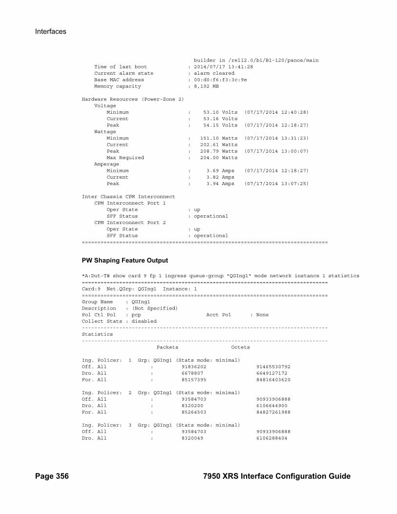
Interfaces
Page 356 7950 XRS Interface Configuration Guide
builder in /rel12.0/b1/B1-120/panos/main Time of last boot : 2014/07/17 13:41:28 Current alarm state : alarm cleared Base MAC address : 00:d0:f6:f3:3c:9e Memory capacity : 8,192 MB
Hardware Resources (Power-Zone 2) Voltage Minimum : 53.10 Volts (07/17/2014 12:40:28) Current : 53.16 Volts Peak : 54.15 Volts (07/17/2014 12:18:27) Wattage Minimum : 151.10 Watts (07/17/2014 13:31:23) Current : 202.61 Watts Peak : 208.79 Watts (07/17/2014 13:00:07) Max Required : 204.00 Watts Amperage Minimum : 3.69 Amps (07/17/2014 12:18:27) Current : 3.82 Amps Peak : 3.94 Amps (07/17/2014 13:07:25)
Inter Chassis CPM Interconnect CPM Interconnect Port 1 Oper State : up SFF Status : operational CPM Interconnect Port 2 Oper State : up SFF Status : operational===============================================================================
PW Shaping Feature Output
*A:Dut-T# show card 9 fp 1 ingress queue-group "QGIng1" mode network instance 1 statistics ===============================================================================Card:9 Net.QGrp: QGIng1 Instance: 1===============================================================================Group Name : QGIng1 Description : (Not Specified)Pol Ctl Pol : pcp Acct Pol : NoneCollect Stats : disabled -------------------------------------------------------------------------------Statistics------------------------------------------------------------------------------- Packets Octets Ing. Policer: 1 Grp: QGIng1 (Stats mode: minimal)Off. All : 91836202 91465530792Dro. All : 6678807 6649127172For. All : 85157395 84816403620 Ing. Policer: 2 Grp: QGIng1 (Stats mode: minimal)Off. All : 93584703 90933906888Dro. All : 8320200 6106644900For. All : 85264503 84827261988 Ing. Policer: 3 Grp: QGIng1 (Stats mode: minimal)Off. All : 93584703 90933906888Dro. All : 8320049 6106288404

Interface Configuration
7950 XRS Interface Configuration Guide Page 357
For. All : 85264654 84827618484 Ing. Policer: 4 Grp: QGIng1 (Stats mode: minimal)Off. All : 93584703 90933906888Dro. All : 8326509 6110568864For. All : 85258194 84823338024 Ing. Policer: 5 Grp: QGIng1 (Stats mode: minimal)Off. All : 93584703 90933906888Dro. All : 24877143 22616873028For. All : 68707560 68317033860 Ing. Policer: 6 Grp: QGIng1 (Stats mode: minimal)Off. All : 93434643 90919501128Dro. All : 24727111 22602499656For. All : 68707532 68317001472 Ing. Policer: 7 Grp: QGIng1 (Stats mode: minimal)Off. All : 93584703 90933906888Dro. All : 24877214 22616941944For. All : 68707489 68316964944 Ing. Policer: 8 Grp: QGIng1 (Stats mode: minimal)Off. All : 93430663 90919119048Dro. All : 24723280 22602263280For. All : 68707383 68316855768 Ing. Policer: 9 Grp: QGIng1 (Stats mode: minimal)Off. All : 0 0Dro. All : 0 0For. All : 0 0 Ing. Policer: 10 Grp: QGIng1 (Stats mode: minimal)Off. All : 0 0Dro. All : 0 0For. All : 0 0 Ing. Policer: 11 Grp: QGIng1 (Stats mode: minimal)Off. All : 0 0Dro. All : 0 0For. All : 0 0 Ing. Policer: 12 Grp: QGIng1 (Stats mode: minimal)Off. All : 0 0Dro. All : 0 0For. All : 0 0 Ing. Policer: 13 Grp: QGIng1 (Stats mode: minimal)Off. All : 0 0Dro. All : 0 0For. All : 0 0 Ing. Policer: 14 Grp: QGIng1 (Stats mode: minimal)Off. All : 0 0Dro. All : 0 0For. All : 0 0 Ing. Policer: 15 Grp: QGIng1 (Stats mode: minimal)Off. All : 0 0

Interfaces
Page 358 7950 XRS Interface Configuration Guide
Dro. All : 0 0For. All : 0 0 Ing. Policer: 16 Grp: QGIng1 (Stats mode: minimal)Off. All : 0 0Dro. All : 0 0For. All : 0 0===============================================================================*A:Dut-T#
cflowd
Syntax
elmi
Syntax elmi
Context show
Description This command displays Ethernet Link Management Interface (eLMI) information.
ELMI Output — The following table describes eLMI output fields.
Field Description
Link Status Status of the E-LMI protocol when the elmi mode is set to uni-n. Link Status will indicate up if eLMI mode is set to "none".
T391 pooling timer used by UNI-C. UNI-N will send the consecutive single EVC asynchronous status messages every (T391/10) rounded to the second interval.
T392 Pooling verification timer for UNI-N
N393 Status counter for UNI-N
Rx Enq. Time Last time when a status enquiry message was received from UNI-C.
Rx Enq Msg Number of status enquiry messages received.
Rx Check Time Last time when a status enquiry E-LMI check message was received.
Rx Inv. SeqNum Counts the number of E-LMI messages received with invalid sequence number.
Enq Timeouts Counts the number of T392 timer expired.
Tx Status Time Last time when a status message was sent by UNI-N.
Tx Status Msg Number of status messages sent by UNI-N.

Interface Configuration
7950 XRS Interface Configuration Guide Page 359
evc
Syntax evc [port-id [vlan vlan-id]]
Context show>elmi
Description This command displays Ethernet Virtual Connections (EVC). No argument displays all the EVC on the service router. The port and VLAN arguments display information related to EVC associated with the port and VLAN.
Parameters port-id — Displays information related to the EVCs configured on the port
Values slot/mda/port
vlan vlan-id — Specifies the VLAN Identifier of the EVC.
Values 0 — 4094, *
Sample Output
*A:Dut-C# show elmi evc ===============================================================================ELMI EVC Table===============================================================================Port Vlan Status Type Evc Id -------------------------------------------------------------------------------1/1/1 10 New-Act P2p EVC11110 1/1/3 30 New-Act P2p EVC11220 1/1/5 100 Act P2p EVC115100 1/1/5 200 Act P2p EVC115200 -------------------------------------------------------------------------------Number of Evcs : 4===============================================================================*A:Dut-C#
A:Dut-C# show elmi evc 1/1/5 ===============================================================================ELMI EVC Table===============================================================================Port Vlan Status Type Evc Id -------------------------------------------------------------------------------1/1/5 100 Act P2p EVC115100 1/1/5 200 Act P2p EVC115200 -------------------------------------------------------------------------------
Tx Check Time Last time when a status eLMI check message was sent by UNI-N.
Tx Async Status Msg
Counter for single EVC asynchronous status messages sent by UNI-N.
Discard Msg Counter for the status enquiry messages discarded due to errors.
Field Description

Interfaces
Page 360 7950 XRS Interface Configuration Guide
Number of Evcs : 2===============================================================================A:Dut-C#
*A:Dut-C# show elmi evc 1/1/5 vlan 100 ===============================================================================Evc Detailed Information===============================================================================Port : 1/1/5 vlanId : 100Evc Status : Act Evc Type : P2pEvc Identifier: EVC115100===============================================================================*A:Dut-C#
uni
Syntax uni [port-id]
Context show>elmi
Description This command displays information about ELMI (mode, status, number of EVCs (SAPs) configure on the port for all the ports on the service router.
Parameters port-id — Displays UNI information for the specified port.
Sample Output
*A:Dut-C# show elmi uni ===============================================================================ELMI UNI-N Table===============================================================================Port Mode Status #Evcs Uni Identifier -------------------------------------------------------------------------------1/1/1 None Up 0 10/100 Ethernet TX 1/1/2 None Up 0 port-21 1/1/3 None Up 0 10/100 Ethernet TX 1/1/4 None Up 0 10/100 Ethernet TX 1/1/5 Uni-N Up 2 UNI115 1/1/6 None Up 0 10/100 Ethernet TX 1/1/7 None Up 0 10/100 Ethernet TX 1/1/8 None Up 0 10/100 Ethernet TX 1/1/9 None Up 0 10/100 Ethernet TX 1/1/10 None Up 0 10/100 Ethernet TX 1/1/11 None Up 0 10/100 Ethernet TX 1/1/12 None Up 0 10/100 Ethernet TX 1/1/13 None Up 0 10/100 Ethernet TX 1/1/14 None Up 0 10/100 Ethernet TX 1/1/15 None Up 0 10/100 Ethernet TX 1/1/16 None Up 0 10/100 Ethernet TX 1/1/17 None Up 0 10/100 Ethernet TX ... ===============================================================================*A:Dut-C#

Interface Configuration
7950 XRS Interface Configuration Guide Page 361
*A:Dut-C# show elmi uni 1/1/5 ===============================================================================Uni-N Detailed Information===============================================================================Uni Mode : Uni-N Link Status : UpUni Identifier: UNI115T391 : 10 seconds T392 : 15 secondsN393 : 4 UniType : BundlingRx Enq. Time : 02/18/2010 17:11:44 Tx Status Time : 02/18/2010 17:11:44Rx Enq Msg : 24 Tx Status Msg : 24Rx Check Time : 02/18/2010 17:12:34 Tx Check Time : 02/18/2010 17:12:34Rx Inv. SeqNum: 0 Tx Async Status Msg : 0Enq Timeouts : 0 Discard Msg : 0===============================================================================*A:Dut-C#
interface-group-handler
Syntax interface-group-handler [igh-id]
Context show
Description This command displays Interface Group Handler (IGH) information.
If no command line options are specified, a summary listing of all IGHs is displayed.
Parameters igh-id — Displays information only on the specified IGH ID.
Sample
A:ALU-27# show interface-group-handler ===============================================================================Interface Group Handler Summary Information===============================================================================IGH Index Admin Number of Threshold State Members -------------------------------------------------------------------------------1 Up 4 4 2 Up 2 2 ===============================================================================A:ALU-27#
A:ALU-27#show interface-group-handler 2 ===============================================================================Interface Group Handler 2 Information===============================================================================Admin Status : Up Threshold : 2 Last Change : 02/02/2010 18:10:04-------------------------------------------------------------------------------Interface Group Handler Protocol Information-------------------------------------------------------------------------------Protocol Oper Status Active Links Up Time-------------------------------------------------------------------------------

Interfaces
Page 362 7950 XRS Interface Configuration Guide
ipcp up 2 0d 00:15:04ipv6cp none 0 N/Amplscp waiting 0 N/Aosicp none 0 N/A-------------------------------------------------------------------------------Port 1/5/2.2 Information-------------------------------------------------------------------------------Protocol Oper Status Up Time-------------------------------------------------------------------------------ipcp up 0d 00:15:05ipv6cp none N/Amplscp running N/Aosicp none N/A-------------------------------------------------------------------------------Port 1/5/2.3 Information-------------------------------------------------------------------------------Protocol Oper Status Up Time-------------------------------------------------------------------------------ipcp up 0d 00:15:05ipv6cp none N/Amplscp running N/Aosicp none N/A===============================================================================A:ALU-27#
mda
Syntax mda [slot [/mda]] [detail]
Context show
Description This command displays MDA (XMA) information.
If no command line options are specified, a summary output of all MDAs is displayed in table format.
Parameters slot — The slot number for which to display MDA information.
Values 1 — 10
mda — The MDA number in the slot for which to display MDA information.
1, 2detail — Displays detailed MDA information.
Output MDA Output — The following table describes MDA output fields.
Label Description
Slot The chassis slot number.
MDA The MDA slot number.
Provisionedtype The MDA type provisioned.
Equippedtype The MDA type actually installed.

Interface Configuration
7950 XRS Interface Configuration Guide Page 363
Sample Output
A:Dut-A# show mda
===============================================================================MDA Summary===============================================================================Slot Mda Provisioned Type Admin Operational Equipped Type (if different) State State-------------------------------------------------------------------------------1 1 cx20-10g-sfp up up 2 cx20-10g-sfp up up2 1 cx20-10g-sfp up up===============================================================================A:Dut-A#
MDA Detailed Output — The following table describes detailed MDA output fields.
Admin State Up — Administratively up.
Down — Administratively down (e.g., shutdown).
Operational State
Up — Operationally up.
Down — Operationally down.
Label Description
Slot The chassis slot number.
Slot The MDA slot number.
Provisioned Pro-visioned-type
The provisioned MDA type.
Equipped Mda-type
The MDA type that is physically inserted into this slot in this chassis.
Admin State Up — The MDA is administratively up.
Down — The MDA is administratively down.
Operational State
Up — The MDA is operationally up.
Down — The MDA is operationally down.
Failure Reason This hardware component has failed.
Maximum port count
The maximum number of ports that can be equipped on the MDA card.
Label Description (Continued)

Interfaces
Page 364 7950 XRS Interface Configuration Guide
Number of ports equipped
The number of ports that are actually equipped on the MDA.
Transmit timing selected
Indicates the source for the timing used by the MDA.
Sync interface timing status
Indicates whether the MDA has qualified one of the timing signals from the CPMs.
Network Ingress Queue Policy
Specifies the network queue policy applied to the MDA to define the queueing structure for this object.
Capabilities Specifies the minimum size of the port that can exist on the MDA.
Egress XPL error threshold
The Egress XPL Error Threshold value used by the fail-on-error feature.
Egress XPL error window
The Egress XPL Error Window value used by the fail-on-error feature.
Max channel size Specifies the maximum size of the channel that can exist on the channelized MDA.
Part number The hardware part number.
CLEI code The code used to identify the MDA.
Serial number The MDA part number. Not user modifiable.
Manufacture date The MDA manufacture date. Not user modifiable.
Manufacturing string
Factory-inputted manufacturing text string. Not user modifiable.
Administrative state
Up — The MDA is administratively up.
Down — The MDA is administratively down.
Operational state
Up — The MDA is operationally up.
Down — The MDA is operationally down.
Time of last boot
The date and time the most recent boot occurred.
Current alarm state
Displays the alarm conditions for the specific MDA.
Base MAC address The base chassis Ethernet MAC address. Special purpose MAC addresses used by the system software are constructed as offsets from this base address.
Label Description (Continued)

Interface Configuration
7950 XRS Interface Configuration Guide Page 365
Sample Output
*A:Dut-A# show mda 5/1 detail
===============================================================================MDA 5/1 detail===============================================================================Slot Mda Provisioned Equipped Admin Operational Mda-type Mda-type State State -------------------------------------------------------------------------------5 1 m20-1gb-xp-sfp m20-1gb-xp-sfp up up
MDA Specific Data Maximum port count : 20 Number of ports equipped : 20 Network ingress queue policy : default Capabilities : Ethernet Fail On Error : disabled Egress XPL error threshold : 1000 Egress XPL error window : 60
Hardware Data Platform type : 7750 Part number : 3HE03612AAAB01 CLEI code : IPPAABFBAA Serial number : NS093464752 Manufacture date : 08232009 Manufacturing string : Manufacturing deviations : Manufacturing assembly number : Administrative state : up Operational state : up Temperature : 37C Temperature threshold : 75C Software version : N/A Time of last boot : 2011/11/15 11:32:49 Current alarm state : alarm cleared Base MAC address : 00:23:3e:ea:38:4b-------------------------------------------------------------------------------QOS Settings-------------------------------------------------------------------------------Ing. Named Pool Policy : NoneEgr. Named Pool Policy : None===============================================================================
A:Dut-A# show mda 1/1 detail
===============================================================================MDA 1/1 detail===============================================================================Slot Mda Provisioned Type Admin Operational Equipped Type (if different) State State-------------------------------------------------------------------------------1 1 cx20-10g-sfp up up
MDA Specific Data Maximum port count : 20

Interfaces
Page 366 7950 XRS Interface Configuration Guide
Number of ports equipped : 20 Network ingress queue policy : default Capabilities : Ethernet Min channel size : Sonet STS-192 Max channel size : Sonet STS-192 Max number of channels : 20 Channels in use : 0
Hardware Data Platform type : 7950 Part number : CLEI code : Serial number : GRA03-126 Manufacture date : Manufacturing string : (Not Specified) Manufacturing deviations : (Not Specified) Manufacturing assembly number : 82-0299-03 Administrative state : up Operational state : up Temperature : 45C Temperature threshold : 75C Software version : N/A Time of last boot : 2012/05/23 20:30:55 Current alarm state : alarm cleared Base MAC address : 8c:90:d3:be:69:8a Firmware version : I-10.0.S209
-------------------------------------------------------------------------------QOS Settings-------------------------------------------------------------------------------===============================================================================A:Dut-A#

Interface Configuration
7950 XRS Interface Configuration Guide Page 367
pools
Syntax pools mda-id [/port] [access-app [pool-name | service service-id]] | queue-group queue-group-name]]pools mda-id [/port] [network-app [pool-name |queue-group queue-group-name]]pools mda-id [/port] [direction [pool-name |service service-id| queue-group queue-group-name]]
Context show
Description This command displays pool information.
Parameters mda-id[/port] — Displays the pool information of the specified MDA and port.
access-app pool-name — Displays the pool information of the specified QoS policy.
Values access-ingress, access-egress
service service-id — Displays pool information for the specified service.
Values 1 — 2147483647
queue-group queue-group-name — Display information for the specified queue group.
direction — Specifies to display information for the ingress or egress direction.
Values ingress, egress
Output Show Pool Output — The following table describes show pool output fields.
Label Description
Type Specifies the pool type.
ID Specifies the card/mda or card/MDA/port designation.
Application/Type Specifies the nature of usage the pool would be used for. The pools could be used for access or network traffic at either ingress or egress.
Pool Name Specifies the name of the pool being used.
Resv CBS Specifies the percentage of pool size reserved for CBS.
Utilization Specifies the type of the slope policy.
State The administrative status of the port.
Start-Avg Specifies the percentage of the buffer utilized after which the drop probability starts to rise above 0.
Max-Avg Specifies the percentage of the buffer utilized after which the drop probability is 100 percent. This implies that all packets beyond this point will be dropped.
Time Avg Factor Specifies the time average factor the weighting between the previous shared buffer average utilization result and the new shared buffer utilization in determining the new shared buffer average utilization.

Interfaces
Page 368 7950 XRS Interface Configuration Guide
*A:ALA-48# show pools 1/1===============================================================================Type Id App. Pool Name Actual ResvCBS PoolSize Admin ResvCBS-------------------------------------------------------------------------------MDA 1/1 Acc-Ing default SumMDA 1/1 Acc-Ing MC Path Mgnt 50MDA 1/1 Acc-Egr default SumMDA 1/1 Net-Ing default SumMDA 1/1 Net-Egr default 50Port 1/1/1 Acc-Ing default SumPort 1/1/1 Acc-Egr default SumPort 1/1/1 Net-Egr default SumPort 1/1/2 Acc-Ing default SumPort 1/1/2 Acc-Egr default SumPort 1/1/2 Net-Egr default SumPort 1/1/3 Acc-Ing default SumPort 1/1/3 Acc-Egr default SumPort 1/1/3 Net-Egr default Sum
Actual ResvCBS Specifies the actual percentage of pool size reserved for CBS.
Admin ResvCBS Specifies the percentage of pool size reserved for CBS.
PoolSize Specifies the size in percentage of buffer space. The value '-1' implies that the pool size should be computed as per fair weighting between all other pools.
Pool Total Displays the total pool size.
Pool Shared Displays the amount of the pool which is shared.
Pool Resv Specifies the percentage of reserved pool size.
Pool Total In Use
Displays the total amount of the pool which is in use.
Pool Shared In Use
Displays the amount of the pool which is shared that is in use.
Label Description (Continued)

Interface Configuration
7950 XRS Interface Configuration Guide Page 369
Port 1/1/4 Acc-Ing default SumPort 1/1/4 Acc-Egr default Sum...Port 1/1/12 Acc-Egr default SumPort 1/1/12 Net-Egr default Sum===============================================================================*A:ALA-48#
*A:ALA-48# show pools 1/1/1 network-egress===============================================================================Pool Information===============================================================================Port : 1/1/1 Application : Net-Egr Pool Name : default Resv CBS : Sum -------------------------------------------------------------------------------Utilization State Start-Avg Max-Avg Max-Prob-------------------------------------------------------------------------------High-Slope Down 70% 90% 80%Low-Slope Down 50% 75% 80% Time Avg Factor : 7 Pool Total : 3072 KB Pool Shared : 1536 KB Pool Resv : 1536 KB Pool Total In Use : 0 KB Pool Shared In Use : 0 KB Pool Resv In Use : 0 KB WA Shared In Use : 0 KB Hi-Slope Drop Prob : 0 Lo-Slope Drop Prob : 0 -------------------------------------------------------------------------------FC-Maps ID MBS Depth A.CIR A.PIR CBS O.CIR O.PIR-------------------------------------------------------------------------------be 1/1/1 1536 0 0 100000 28 0 Max l2 1/1/1 1536 0 25000 100000 96 25000 Max af 1/1/1 1536 0 25000 100000 320 25000 Max l1 1/1/1 768 0 25000 100000 96 25000 Max h2 1/1/1 1536 0 100000 100000 320 Max Max ef 1/1/1 1536 0 100000 100000 320 Max Max h1 1/1/1 768 0 10000 100000 96 10000 Max nc 1/1/1 768 0 10000 100000 96 10000 Max ===============================================================================*A:ALA-48#
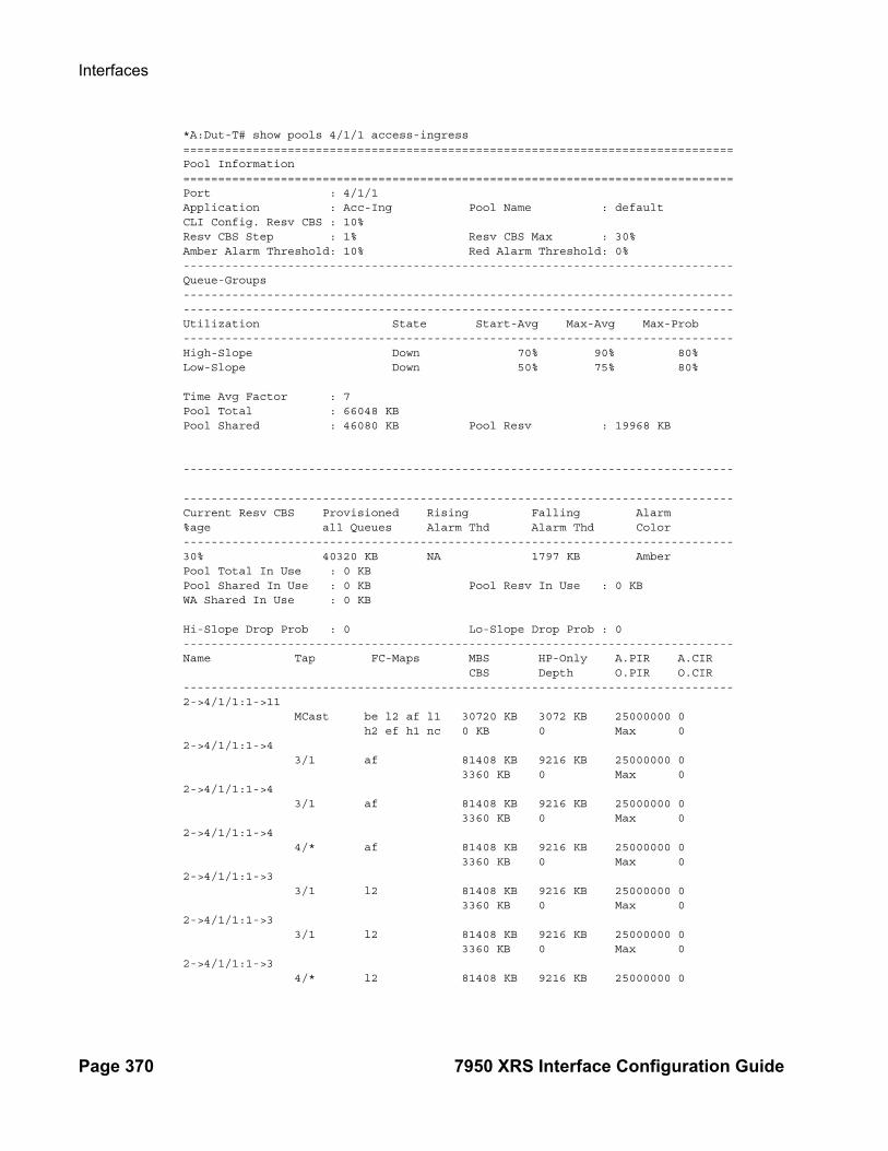
Interfaces
Page 370 7950 XRS Interface Configuration Guide
*A:Dut-T# show pools 4/1/1 access-ingress ===============================================================================Pool Information===============================================================================Port : 4/1/1 Application : Acc-Ing Pool Name : defaultCLI Config. Resv CBS : 10% Resv CBS Step : 1% Resv CBS Max : 30%Amber Alarm Threshold: 10% Red Alarm Threshold: 0%-------------------------------------------------------------------------------Queue-Groups--------------------------------------------------------------------------------------------------------------------------------------------------------------Utilization State Start-Avg Max-Avg Max-Prob-------------------------------------------------------------------------------High-Slope Down 70% 90% 80%Low-Slope Down 50% 75% 80% Time Avg Factor : 7 Pool Total : 66048 KB Pool Shared : 46080 KB Pool Resv : 19968 KB ------------------------------------------------------------------------------- -------------------------------------------------------------------------------Current Resv CBS Provisioned Rising Falling Alarm%age all Queues Alarm Thd Alarm Thd Color-------------------------------------------------------------------------------30% 40320 KB NA 1797 KB AmberPool Total In Use : 0 KB Pool Shared In Use : 0 KB Pool Resv In Use : 0 KBWA Shared In Use : 0 KB Hi-Slope Drop Prob : 0 Lo-Slope Drop Prob : 0-------------------------------------------------------------------------------Name Tap FC-Maps MBS HP-Only A.PIR A.CIR CBS Depth O.PIR O.CIR-------------------------------------------------------------------------------2->4/1/1:1->11 MCast be l2 af l1 30720 KB 3072 KB 25000000 0 h2 ef h1 nc 0 KB 0 Max 02->4/1/1:1->4 3/1 af 81408 KB 9216 KB 25000000 0 3360 KB 0 Max 02->4/1/1:1->4 3/1 af 81408 KB 9216 KB 25000000 0 3360 KB 0 Max 02->4/1/1:1->4 4/* af 81408 KB 9216 KB 25000000 0 3360 KB 0 Max 02->4/1/1:1->3 3/1 l2 81408 KB 9216 KB 25000000 0 3360 KB 0 Max 02->4/1/1:1->3 3/1 l2 81408 KB 9216 KB 25000000 0 3360 KB 0 Max 02->4/1/1:1->3 4/* l2 81408 KB 9216 KB 25000000 0

Interface Configuration
7950 XRS Interface Configuration Guide Page 371
3360 KB 0 Max 02->4/1/1:1->2 3/1 l1 81408 KB 9216 KB 25000000 0 3360 KB 0 Max 02->4/1/1:1->2 3/1 l1 81408 KB 9216 KB 25000000 0 3360 KB 0 Max 02->4/1/1:1->2 4/* l1 81408 KB 9216 KB 25000000 0...===============================================================*A:Dut-T#
*A:ALU-2011# show pools 2/1/1 access-egress===============================================================Pool Information===============================================================Port : 2/1/1Application : Acc-Egr Pool Name : defaultResv CBS : Sum-------------------------------------------------------------------------------Queue-Groups-------------------------------------------------------------------------------policer-output-queues-------------------------------------------------------------------------------Utilization State Start-Avg Max-Avg Max-Prob-------------------------------------------------------------------------------High-Slope Down 70% 90% 80%Low-Slope Down 50% 75% 80%
Time Avg Factor : 7Pool Total : 6336 KBPool Shared : 4416 KB Pool Resv : 1920 KB
-------------------------------------------------------------------------------Pool Resv CBS Provisioned Rising Falling Alarm %age All Queues Alarm Thd Alarm Thd Color ------------------------------------------------------------------------------- 40% 300KB 350KB 250KB Amber Pool Total In Use : 0 KBPool Shared In Use : 0 KB Pool Resv In Use : 0 KBWA Shared In Use : 0 KB
Hi-Slope Drop Prob : 0 Lo-Slope Drop Prob : 0-------------------------------------------------------------------------------Name Tap FC-Maps MBS HP-Only A.PIR A.CIR CBS Depth O.PIR O.CIR-------------------------------------------------------------------------------2->2/1/1:100->1
be l2 af l1 123 KB 15 KB 100000 0h2 ef h1 nc 0 KB 0 Max 0
accQGrp->policer-output-queues(2/1/1)->1n/a 123 KB 15 KB 100000 0
0 KB 0 Max 0accQGrp->policer-output-queues(2/1/1)->2
n/a 123 KB 15 KB 100000 0
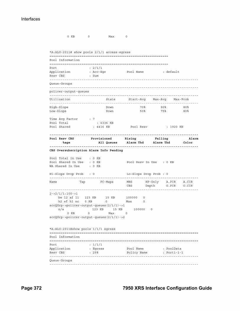
Interfaces
Page 372 7950 XRS Interface Configuration Guide
0 KB 0 Max 0
*A:ALU-2011# show pools 2/1/1 access-egress===============================================================Pool Information===============================================================Port : 2/1/1Application : Acc-Egr Pool Name : defaultResv CBS : Sum-------------------------------------------------------------------------------Queue-Groups-------------------------------------------------------------------------------policer-output-queues-------------------------------------------------------------------------------Utilization State Start-Avg Max-Avg Max-Prob-------------------------------------------------------------------------------High-Slope Down 70% 90% 80%Low-Slope Down 50% 75% 80%
Time Avg Factor : 7Pool Total : 6336 KBPool Shared : 4416 KB Pool Resv : 1920 KB
-------------------------------------------------------------------------------Pool Resv CBS Provisioned Rising Falling Alarm %age All Queues Alarm Thd Alarm Thd Color -------------------------------------------------------------------------------CBS Oversubscription Alarm Info Pending
Pool Total In Use : 0 KBPool Shared In Use : 0 KB Pool Resv In Use : 0 KBWA Shared In Use : 0 KB
Hi-Slope Drop Prob : 0 Lo-Slope Drop Prob : 0-------------------------------------------------------------------------------Name Tap FC-Maps MBS HP-Only A.PIR A.CIR CBS Depth O.PIR O.CIR-------------------------------------------------------------------------------2->2/1/1:100->1
be l2 af l1 123 KB 15 KB 100000 0h2 ef h1 nc 0 KB 0 Max 0
accQGrp->policer-output-queues(2/1/1)->1n/a 123 KB 15 KB 100000 0
0 KB 0 Max 0accQGrp->policer-output-queues(2/1/1)->2
*A:ALU-2011#show pools 1/1/1 egress===============================================================================Pool Information===============================================================================Port : 1/1/1Application : Egress Pool Name : PoolDataResv CBS : 25% Policy Name : Port1-1-1-------------------------------------------------------------------------------Queue-Groups-------------------------------------------------------------------------------

Interface Configuration
7950 XRS Interface Configuration Guide Page 373
-------------------------------------------------------------------------------Utilization State Start-Avg Max-Avg Max-Prob-------------------------------------------------------------------------------High-Slope Down 70% 90% 80%Low-Slope Down 50% 75% 80%Time Avg Factor : 7Pool Total : 64 KBPool Shared : 48 KB Pool Resv : 16 KB-------------------------------------------------------------------------------Pool Resv CBS Provisioned Rising Falling Alarm %age All Queues Alarm Thd Alarm Thd Color ------------------------------------------------------------------------------- 40% 300KB 350KB 250KB AmberPool Total In Use : 0 KBPool Shared In Use : 0 KB Pool Resv In Use : 0 KBWA Shared In Use : 0 KBHi-Slope Drop Prob : 0 Lo-Slope Drop Prob : 0-------------------------------------------------------------------------------Name Tap FC-Maps MBS HP-Only A.PIR A.CIR CBS Depth O.PIR O.CIR-------------------------------------------------------------------------------1->1/1/1:10->2 af 128 KB 16 KB 100000 0 0 KB 0 Max 01->1/1/1:10->4 l1 128 KB 16 KB 100000 0 0 KB 0 Max 0-------------------------------------------------------------------------------Port : 1/1/1Application : Egress Pool Name : PoolVideoResv CBS : 25% Policy Name : Port1-1-1-------------------------------------------------------------------------------Queue-Groups--------------------------------------------------------------------------------------------------------------------------------------------------------------Utilization State Start-Avg Max-Avg Max-Prob-------------------------------------------------------------------------------High-Slope Down 70% 90% 80%Low-Slope Down 50% 75% 80%Time Avg Factor : 7Pool Total : 64 KBPool Shared : 48 KB Pool Resv : 16 KB-------------------------------------------------------------------------------Pool Resv CBS Provisioned Rising Falling Alarm %age All Queues Alarm Thd Alarm Thd Color ------------------------------------------------------------------------------- 40% 300KB 350KB 250KB AmberPool Total In Use : 0 KBPool Shared In Use : 0 KB Pool Resv In Use : 0 KBWA Shared In Use : 0 KBHi-Slope Drop Prob : 0 Lo-Slope Drop Prob : 0-------------------------------------------------------------------------------Name Tap FC-Maps MBS HP-Only A.PIR A.CIR CBS Depth O.PIR O.CIR-------------------------------------------------------------------------------1->1/1/1:10->5 ef 128 KB 16 KB 100000 0 0 KB 0 Max 0-------------------------------------------------------------------------------

Interfaces
Page 374 7950 XRS Interface Configuration Guide
Port : 1/1/1Application : Egress Pool Name : PoolVoiceResv CBS : 50% Policy Name : Port1-1-1-------------------------------------------------------------------------------Queue-Groups--------------------------------------------------------------------------------------------------------------------------------------------------------------Utilization State Start-Avg Max-Avg Max-Prob-------------------------------------------------------------------------------High-Slope Down 70% 90% 80%Low-Slope Down 50% 75% 80%Time Avg Factor : 7Pool Total : 64 KBPool Shared : 32 KB Pool Resv : 32 KB-------------------------------------------------------------------------------Pool Resv CBS Provisioned Rising Falling Alarm %age All Queues Alarm Thd Alarm Thd Color ------------------------------------------------------------------------------- 40% 300KB 350KB 250KB AmberPool Total In Use : 0 KBPool Shared In Use : 0 KB Pool Resv In Use : 0 KBWA Shared In Use : 0 KBHi-Slope Drop Prob : 0 Lo-Slope Drop Prob : 0-------------------------------------------------------------------------------Name Tap FC-Maps MBS HP-Only A.PIR A.CIR CBS Depth O.PIR O.CIR-------------------------------------------------------------------------------1->1/1/1:10->3 nc 128 KB 16 KB 100000 0 0 KB 0 Max 0===============================================================================*A:ALU-2011#
When alarm information is pending:
*A:Dut-T# show pools 4/1/1 access-ingress ===============================================================================Pool Information===============================================================================Port : 4/1/1 Application : Acc-Ing Pool Name : defaultCLI Config. Resv CBS : 10% Resv CBS Step : 1% Resv CBS Max : 35%Amber Alarm Threshold: 10% Red Alarm Threshold: 0%-------------------------------------------------------------------------------Queue-Groups-------------------------------------------------------------------------------Utilization State Start-Avg Max-Avg Max-Prob-------------------------------------------------------------------------------High-Slope Down 70% 90% 80%Low-Slope Down 50% 75% 80% Time Avg Factor : 7 Pool Total : 66048 KB Pool Shared : 46080 KB Pool Resv : 19968 KB --------------------------------------------------------------------------------------------------------------------------------------------------------------Current Resv CBS Provisioned Rising Falling Alarm

Interface Configuration
7950 XRS Interface Configuration Guide Page 375
%age all Queues Alarm Thd Alarm Thd Color-------------------------------------------------------------------------------CBS Oversubscription Alarm Info PendingPool Total In Use : 0 KB Pool Shared In Use : 0 KB Pool Resv In Use : 0 KBWA Shared In Use : 0 KB Hi-Slope Drop Prob : 0 Lo-Slope Drop Prob : 0-------------------------------------------------------------------------------Name Tap FC-Maps MBS HP-Only A.PIR A.CIR CBS Depth O.PIR O.CIR-------------------------------------------------------------------------------2->4/1/1:1->11 MCast be l2 af l1 30720 KB 3072 KB 25000000 0 h2 ef h1 nc 0 KB 0 Max 02->4/1/1:1->4 3/1 af 81408 KB 9216 KB 25000000 0 3360 KB 0 Max 02->4/1/1:1->4 3/1 af 81408 KB 9216 KB 25000000 0 3360 KB 0 Max 02->4/1/1:1->4 4/* af 81408 KB 9216 KB 25000000 0 3360 KB 0 Max 02->4/1/1:1->3 3/1 l2 81408 KB 9216 KB 25000000 0 3360 KB 0 Max 02->4/1/1:1->3 3/1 l2 81408 KB 9216 KB 25000000 0 3360 KB 0 Max 02->4/1/1:1->3 4/* l2 81408 KB 9216 KB 25000000 0 3360 KB 0 Max 02->4/1/1:1->2 3/1 l1 81408 KB 9216 KB 25000000 0 3360 KB 0 Max 02->4/1/1:1->2 3/1 l1 81408 KB 9216 KB 25000000 0 3360 KB 0 Max 02->4/1/1:1->2 4/* l1 81408 KB 9216 KB 25000000 0 3360 KB 0 Max 02->4/1/1:1->1 3/1 be h2 ef h1 81408 KB 9216 KB 25000000 0 nc 3360 KB 0 Max 02->4/1/1:1->1 3/1 be h2 ef h1 81408 KB 9216 KB 25000000 0 nc 3360 KB 0 Max 02->4/1/1:1->1 4/* be h2 ef h1 81408 KB 9216 KB 25000000 0 nc 3360 KB 0 Max 0===============================================================================*A:Dut-T#

Interfaces
Page 376 7950 XRS Interface Configuration Guide
When alarm information is pending:
*A:Dut-T# show pools 9/2/1 egress ===============================================================================Pool Information===============================================================================Port : 9/2/1 Application : Egress Pool Name : pool1CLI Config. Resv CBS : 10% Policy Name : namedEgrResv CBS Step : 1% Resv CBS Max : 35%Amber Alarm Threshold: 30% Red Alarm Threshold: 45%-------------------------------------------------------------------------------Queue-Groups-------------------------------------------------------------------------------Utilization State Start-Avg Max-Avg Max-Prob-------------------------------------------------------------------------------High-Slope Down 70% 90% 80%Low-Slope Down 50% 75% 80% Time Avg Factor : 7 Pool Total : 258 KB Pool Shared : 192 KB Pool Resv : 66 KB --------------------------------------------------------------------------------------------------------------------------------------------------------------Current Resv CBS Provisioned Rising Falling Alarm%age all Queues Alarm Thd Alarm Thd Color-------------------------------------------------------------------------------CBS Oversubscription Alarm Info PendingPool Total In Use : 0 KB Pool Shared In Use : 0 KB Pool Resv In Use : 0 KBWA Shared In Use : 0 KB Hi-Slope Drop Prob : 0 Lo-Slope Drop Prob : 0-------------------------------------------------------------------------------Name Tap FC-Maps MBS HP-Only A.PIR A.CIR CBS Depth O.PIR O.CIR-------------------------------------------------------------------------------1 Net=be Port=9/2/1 be 66048 B 7680 B 1000000 0 39 KB 0 Max 0-------------------------------------------------------------------------------*A:Dut-T#
In Use Stat Note:
The pool shared in use stat only increases when a queue is asking for a buffer outside it’s reserved size. If all the buffers in a pool are assigned to queues within their reserved size, then only the reserved in use size will increase. In case of resv CBS oversubscription (CBS sum for all queues is bigger then pool resvCbs), it is possible that pool resv in use stat can increase above the actual pool reserved size. For example:
Pool Total : 57344 KB Pool Shared : 32768 KB Pool Resv : 24576 KB
Pool Total In Use : 57344 KB Pool Shared In Use : 0 KB Pool Resv In Use: 57344 KB

Interface Configuration
7950 XRS Interface Configuration Guide Page 377
Show PEQ Commands
peq
Syntax peq [peq-slot] [detail]
Context show
Description This command displays APEQ information.
Output PEQ Output Fields — The following table describes peq output fields:
Label Description
Slot The number of the slot in which the APEQ is installed.
Provisioned TypeEquipped Type (if different)
The APEQ type provisioned.
Admin State The administrative state.
Operational State The operational state.
Input Specifies the input battery feed: A, or B
Zone Specifies the chassis power zone.
Hardware Data:
Part number The APEQ part number.
CLEI code The APEQ CLEI code.
Serial number The APEQ serial number.
Manufacture date The date the APEQ was manufactured
Manufacturing devia-tions
Specifies any manufacturing deviations.
Manufacturing assem-bly number
The APEQ assembly number.
Administrative state Specifies the administrative state of the APEQ.
Operational state Specifies the operational state of the APEQ.
Time of last boot Indicates the time stamp of the last system restart.
Current alarm state Indicates the current alarm state.

Interfaces
Page 378 7950 XRS Interface Configuration Guide
Sample Output
*A:Dut-A# show peq
===============================================================================PEQ Summary===============================================================================Slot Provisioned Type Admin Operational Input Zone Equipped Type (if different) State State A B -------------------------------------------------------------------------------1 apeq-dc-2000 down down Y N 12 (not provisioned) up unprovisioned Y N 1 apeq-dc-2000 3 apeq-dc-2000 up up Y N 14 apeq-dc-2000 up up Y N 15 apeq-dc-2000 up up Y N 16 apeq-dc-2000 up up Y N 17 apeq-dc-2000 up up Y N 18 apeq-dc-2000 up up Y N 19 apeq-dc-2000 up up Y N 110 apeq-dc-2000 up up Y N 111 apeq-dc-2000 up up Y N 112 apeq-dc-2000 up up Y N 1===============================================================================*A:Dut-A# show peq 1
===============================================================================PEQ 1===============================================================================Slot Provisioned Type Admin Operational Input Zone Equipped Type (if different) State State A B -------------------------------------------------------------------------------1 apeq-dc-2000 down down Y N 1===============================================================================
*A:Dut-A# show peq 1 detail
===============================================================================PEQ 1===============================================================================Slot Provisioned Type Admin Operational Input Zone Equipped Type (if different) State State A B -------------------------------------------------------------------------------1 apeq-dc-2000 down down Y N 1
Hardware Data Part number : 3HE07114AARA01 CLEI code : IPUPAJHUAA Serial number : NS1250G0116 Manufacture date : 12202012 Manufacturing deviations : (Not Specified) Manufacturing assembly number: 8205320107 Time of last boot : 2014/01/07 11:01:44 Current alarm state : alarm active===============================================================================
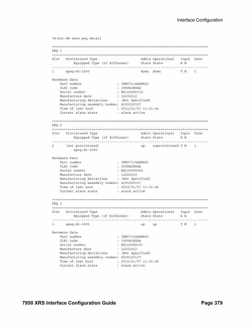
Interface Configuration
7950 XRS Interface Configuration Guide Page 379
*A:Dut-A# show peq detail
===============================================================================PEQ 1===============================================================================Slot Provisioned Type Admin Operational Input Zone Equipped Type (if different) State State A B -------------------------------------------------------------------------------1 apeq-dc-2000 down down Y N 1
Hardware Data Part number : 3HE07114AARA01 CLEI code : IPUPAJHUAA Serial number : NS1250G0116 Manufacture date : 12202012 Manufacturing deviations : (Not Specified) Manufacturing assembly number: 8205320107 Time of last boot : 2014/01/07 11:01:44 Current alarm state : alarm active
===============================================================================PEQ 2===============================================================================Slot Provisioned Type Admin Operational Input Zone Equipped Type (if different) State State A B -------------------------------------------------------------------------------2 (not provisioned) up unprovisioned Y N 1 apeq-dc-2000
Hardware Data Part number : 3HE07114AARA01 CLEI code : IPUPAJHUAA Serial number : NS1249G0022 Manufacture date : 12202012 Manufacturing deviations : (Not Specified) Manufacturing assembly number: 8205320107 Time of last boot : 2014/01/07 11:01:44 Current alarm state : alarm active
===============================================================================PEQ 3 ===============================================================================Slot Provisioned Type Admin Operational Input Zone Equipped Type (if different) State State A B -------------------------------------------------------------------------------3 apeq-dc-2000 up up Y N 1
Hardware Data Part number : 3HE07114AARA01 CLEI code : IPUPAJHUAA Serial number : NS1250G0141 Manufacture date : 12202012 Manufacturing deviations : (Not Specified) Manufacturing assembly number: 8205320107 Time of last boot : 2014/01/07 11:01:44 Current alarm state : alarm active

Interfaces
Page 380 7950 XRS Interface Configuration Guide
===============================================================================PEQ 4===============================================================================Slot Provisioned Type Admin Operational Input Zone Equipped Type (if different) State State A B -------------------------------------------------------------------------------4 apeq-dc-2000 up up Y N 1
Hardware Data Part number : 3HE07114AARA01 CLEI code : IPUPAJHUAA Serial number : NS1249G0201 Manufacture date : 12202012 Manufacturing deviations : (Not Specified) Manufacturing assembly number: 8205320107 Time of last boot : 2014/01/07 11:01:44 Current alarm state : alarm active
===============================================================================PEQ 5===============================================================================Slot Provisioned Type Admin Operational Input Zone Equipped Type (if different) State State A B -------------------------------------------------------------------------------5 apeq-dc-2000 up up Y N 1
Hardware Data Part number : 3HE07114AARA01 CLEI code : IPUPAJHUAA Serial number : NS1250G0123 Manufacture date : 12202012 Manufacturing deviations : (Not Specified) Manufacturing assembly number: 8205320107 Time of last boot : 2014/01/07 11:01:44 Current alarm state : alarm active
===============================================================================PEQ 6===============================================================================Slot Provisioned Type Admin Operational Input Zone Equipped Type (if different) State State A B -------------------------------------------------------------------------------6 apeq-dc-2000 up up Y N 1
Hardware Data Part number : 3HE07114AARA01 CLEI code : IPUPAJHUAA Serial number : NS1250G0061 Manufacture date : 12182012 Manufacturing deviations : (Not Specified) Manufacturing assembly number: 8205320107 Time of last boot : 2014/01/07 11:01:44 Current alarm state : alarm active
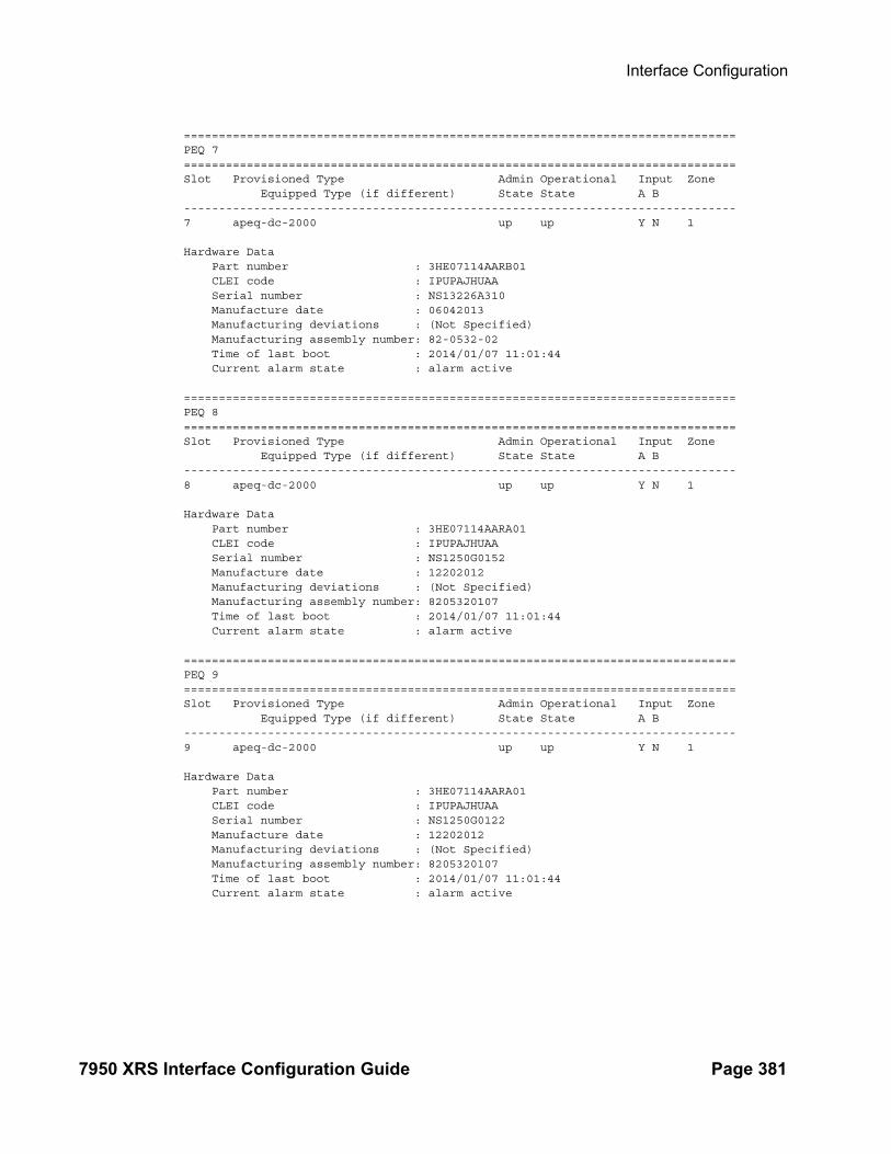
Interface Configuration
7950 XRS Interface Configuration Guide Page 381
===============================================================================PEQ 7===============================================================================Slot Provisioned Type Admin Operational Input Zone Equipped Type (if different) State State A B -------------------------------------------------------------------------------7 apeq-dc-2000 up up Y N 1
Hardware Data Part number : 3HE07114AARB01 CLEI code : IPUPAJHUAA Serial number : NS13226A310 Manufacture date : 06042013 Manufacturing deviations : (Not Specified) Manufacturing assembly number: 82-0532-02 Time of last boot : 2014/01/07 11:01:44 Current alarm state : alarm active
===============================================================================PEQ 8===============================================================================Slot Provisioned Type Admin Operational Input Zone Equipped Type (if different) State State A B -------------------------------------------------------------------------------8 apeq-dc-2000 up up Y N 1
Hardware Data Part number : 3HE07114AARA01 CLEI code : IPUPAJHUAA Serial number : NS1250G0152 Manufacture date : 12202012 Manufacturing deviations : (Not Specified) Manufacturing assembly number: 8205320107 Time of last boot : 2014/01/07 11:01:44 Current alarm state : alarm active
===============================================================================PEQ 9===============================================================================Slot Provisioned Type Admin Operational Input Zone Equipped Type (if different) State State A B -------------------------------------------------------------------------------9 apeq-dc-2000 up up Y N 1
Hardware Data Part number : 3HE07114AARA01 CLEI code : IPUPAJHUAA Serial number : NS1250G0122 Manufacture date : 12202012 Manufacturing deviations : (Not Specified) Manufacturing assembly number: 8205320107 Time of last boot : 2014/01/07 11:01:44 Current alarm state : alarm active

Interfaces
Page 382 7950 XRS Interface Configuration Guide
===============================================================================PEQ 10===============================================================================Slot Provisioned Type Admin Operational Input Zone Equipped Type (if different) State State A B -------------------------------------------------------------------------------10 apeq-dc-2000 up up Y N 1
Hardware Data Part number : 3HE07114AARA01 CLEI code : IPUPAJHUAA Serial number : NS1250G0146 Manufacture date : 12202012 Manufacturing deviations : (Not Specified) Manufacturing assembly number: 8205320107 Time of last boot : 2014/01/07 11:01:44 Current alarm state : alarm active
===============================================================================PEQ 11===============================================================================Slot Provisioned Type Admin Operational Input Zone Equipped Type (if different) State State A B -------------------------------------------------------------------------------11 apeq-dc-2000 up up Y N 1
Hardware Data Part number : 3HE07114AARA01 CLEI code : IPUPAJHUAA Serial number : NS1249G0202 Manufacture date : 12202012 Manufacturing deviations : (Not Specified) Manufacturing assembly number: 8205320107 Time of last boot : 2014/01/07 11:01:44 Current alarm state : alarm active ===============================================================================PEQ 12===============================================================================Slot Provisioned Type Admin Operational Input Zone Equipped Type (if different) State State A B -------------------------------------------------------------------------------12 apeq-dc-2000 up up Y N 1
Hardware Data Part number : 3HE07114AARA01 CLEI code : IPUPAJHUAA Serial number : NS1250G0115 Manufacture date : 12202012 Manufacturing deviations : (Not Specified) Manufacturing assembly number: 8205320107 Time of last boot : 2014/01/07 11:01:44 Current alarm state : alarm active===============================================================================

Interface Configuration
7950 XRS Interface Configuration Guide Page 383
megapools
Syntax megapools slot-numbermegapools slot-number fp forwarding-plane [service-id service-id] [queue-group queue-group-name] [ingress | egress]
Context show
Description This command displays megapool information. A megapool is a mechanism the IOM-3 flexpath traffic manager uses to allow oversubscription of buffer pools. Every buffer pool is created in the context of a megapool.
By default, all buffer pools are associated with a single megapool and the pools are not oversubscribed. When WRED queue support is enabled on the IOM, three megapools are used.
• The original megapool services the default and named pools.
• The second megapool services the system internal use pools.
• The third megapool is used by the buffer pools used by the WRED queues.
The traffic manager buffers are allocated to the three megapools without oversubscription. The WRED queue pools are allowed to oversubscribe their megapool, but the megapool protects the pools associated with the other megapools from buffer starvation that could be caused by that oversubscription.
Parameters slot-number — Displays information for the specified card slot.
fp-number — The fp-number parameter is optional following the fp command. If omitted, the system assumes forwarding plane number 1.
queue-group queue-group-name — Displays information for the specified port queue group name.
ingress — Displays ingress queue group information.
egress — Displays egress queue group information.
sfm
Syntax sfm sfm-id icport [down] [degraded] [detail]
Context show
Description This command displays SFM status information.
Parameters sfm-id — Specifies the SFM identifier.
icport — Displays interconnect port information.
detail — Displays detailed MDA information.
Output PEQ Output Fields — The following table describes sfm output fields.
Label Description
Slot The number of the slot in which the SFM is installed.

Interfaces
Page 384 7950 XRS Interface Configuration Guide
Provisioned TypeEquipped Type (if different)
The SFM type provisioned.
Admin State The administrative state.
Operational State The operational state.
Hardware Data:
Part number The SFM part number.
CLEI code The SFM CLEI code.
Serial number The SFM serial number.
Manufacture date The date the SFM was manufactured
Manufacturing devia-tions
Specifies any manufacturing deviations.
Manufacturing assem-bly number
The SFM assembly number.
Administrative state Specifies the administrative state of the SFM.
Operational state Specifies the operational state of the SFM.
Time of last boot Indicates the time stamp of the last system restart.
Current alarm state Indicates the current alarm state.
Inter Chassis SFM Interconnect
SFM Interconnect Port
Port number
oper state Up — The MDA is administratively up.
Down — The MDA is administratively down.
Misconnect Info Only displayed if the oper state is invalid-connection.
SFF Status
fabric degrade state Indicates state.
Transceiver Data
Tranceiver Type Type of transceiver; for example, CXP
TX Laser Wavelenght Transmit wavelength in nano meters
Number of Lanes Number of lenses for this transceiver
Label Description (Continued)
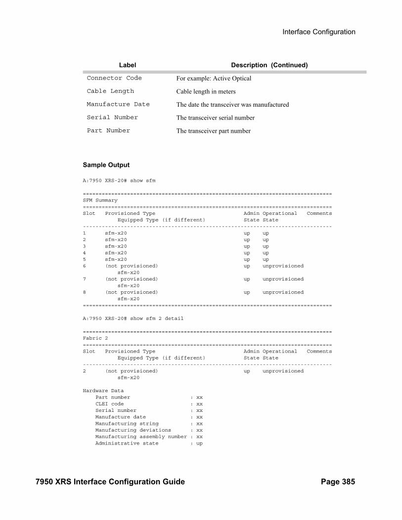
Interface Configuration
7950 XRS Interface Configuration Guide Page 385
Sample Output
A:7950 XRS-20# show sfm
===============================================================================SFM Summary===============================================================================Slot Provisioned Type Admin Operational Comments Equipped Type (if different) State State-------------------------------------------------------------------------------1 sfm-x20 up up2 sfm-x20 up up3 sfm-x20 up up4 sfm-x20 up up5 sfm-x20 up up6 (not provisioned) up unprovisioned sfm-x207 (not provisioned) up unprovisioned sfm-x208 (not provisioned) up unprovisioned sfm-x20===============================================================================
A:7950 XRS-20# show sfm 2 detail
===============================================================================Fabric 2===============================================================================Slot Provisioned Type Admin Operational Comments Equipped Type (if different) State State-------------------------------------------------------------------------------2 (not provisioned) up unprovisioned sfm-x20
Hardware Data Part number : xx CLEI code : xx Serial number : xx Manufacture date : xx Manufacturing string : xx Manufacturing deviations : xx Manufacturing assembly number : xx Administrative state : up
Connector Code For example: Active Optical
Cable Length Cable length in meters
Manufacture Date The date the transceiver was manufactured
Serial Number The transceiver serial number
Part Number The transceiver part number
Label Description (Continued)

Interfaces
Page 386 7950 XRS Interface Configuration Guide
Operational state : unprovisioned Time of last boot : N/A Current alarm state : alarm cleared===============================================================================
Inter Chassis SFM InterconnectSFM Interconnect Port 1
oper state : no-linkMisconnect Info : Fabric 3 IcPort 14
SFF Status : not-equippedfabric degrade state : none
*A:myNode# show sfm icport===============================================================================SFM Interconnect Port Summary===============================================================================SFM SFM IcPort IcPort Module Degrade Miscon.Info
Oper State Num Oper State Inserted State SFM IcPort-------------------------------------------------------------------------------1 unprovisioned 1 up yes none1 unprovisioned 2 invalid-conne* no degraded 3 142 up 2 indeterminate no none2 up 3 up no degraded2 up 5 no-link no none2 up 14 indeterminate yes degraded===============================================================================* indicates that the corresponding row element may have been truncated.===============================================================================
*A:myNode# show sfm icport down===============================================================================SFM Interconnect Port Summary===============================================================================SFM SFM IcPort IcPort Module Degrade Miscon. Info
Oper State Num Oper State Inserted State SFM IcPort-------------------------------------------------------------------------------1 unprovisioned 2 invalid-conne* no degraded 3 142 up 2 indeterminate no none2 up 5 no-link no none2 up 14 indeterminate yes degraded===============================================================================* indicates that the corresponding row element may have been truncated.
*A:myNode# show sfm icport degraded===============================================================================SFM Interconnect Port Summary===============================================================================SFM SFM IcPort IcPort Module Degrade Miscon. Info
Oper State Num Oper State Inserted State SFM IcPort-------------------------------------------------------------------------------2 up 3 up no degraded2 up 14 indeterminate yes degraded===============================================================================

Interface Configuration
7950 XRS Interface Configuration Guide Page 387
Port Show Commands
port
Syntax port port-id [count] [detail]port port-id description port port-id associationsport port-id queue-group [ingress|egress] [queue-group-name] [access|network] [{statistics|associations}]port port-id queue-group qgrp-id [instance instance-id] queue-depth [queue queue-id] [ingress|egress] [access|network]port port-id ethernet [[efm-oam [event-logs {failure|degraded} {active|cleared}] | detailed]port port-id dot1x [detail]port port-id vport [vport-name] associationsport port-id vport [vport-name] monitor-threshold
Context show
Description This command displays port or channel information.
If no command line options are specified, the command port displays summary information for all ports on provisioned MDAs.
Parameters port-id — Specifies the physical port ID in the form slot/mda/port.
Syntax port-id slot[/mda[/port]] orslot/mda/port[.channel]
MDA Values 1, 2
Slot Values 1—10
Port Values 1 — 60 (depending on the MDA type)
associations — Displays a list of current router interfaces to which the port is associated.
count — Displays only port counter summary information.
description — Displays port description strings.
dot1x — Displays information.about 802.1x status and statistics.
down-when-looped — Displays status of port and whether the feature is enabled.
ethernet — Displays ethernet port information.
efm-oam — Displays EFM OAM information.
event-logs — Displays all active and historical event logs.
failure — Displays the active and cleared failure events.
degraded — Displays the active and cleared failure events.

Interfaces
Page 388 7950 XRS Interface Configuration Guide
active — Displays only the active events.
cleared — Displays only the cleared events.
detail — Displays detailed information about the Ethernet port.
detail — Provides detailed information.
vport — Displays Vport information.
associations — Displays a list of ports to which the Vport is assigned.
monitor-threshold — Displays the exceed-count for the port-scheduler under Vport (if specified) or for a physical port.
detail — Provides detailed information.
Output Port Output — The following tables describe port output fields:
• General Port Output Fields on page 388
• Entering port ranges: on page 391
• Specific Port Output Fields on page 391
• Detailed Port Output Fields on page 398
• Ethernet Output on page 405
• Ethernet-Like Medium Statistics Output Fields on page 407
• Port Associations Output Fields on page 410
General Port Output Fields
Label Description
Port ID The port ID configured or displayed in the slot/mda/port format.
Admin State Up — The administrative state is up.
Down — The administrative state is down.
Phy Link Yes — A physical link is present.
No — A physical link is not present.
Port State Up — The port is physically present and has physical link present.
Down — The port is physically present but does not have a link. Note that this state may also be considered as Link Down.
Ghost — A port that is not physically present.
None — The port is in its initial creation state or about to be deleted.
Link Up — A port that is physically present and has physical link present.
Cfg MTU The configured MTU.

Interface Configuration
7950 XRS Interface Configuration Guide Page 389
Sample Output
*A:HW_Node_A# show port 1/1/1
===============================================================================Ethernet Oam (802.3ah)===============================================================================Admin State : downOper State : disabled (protocol state)Ignore-efm-state : Enabled/Disabled===============================================================================
*A:7950 XRS-20# show port 1/1/1
===============================================================================Ethernet Interface===============================================================================Description : 10-Gig EthernetInterface : 1/1/1 Oper Speed : 10 GbpsLink-level : Ethernet Config Speed : N/AAdmin State : down Oper Duplex : full
Oper MTU The negotiated size of the largest packet which can be sent on the port specified in octets.
LAG ID The LAG or multi-link trunk (MLT) that the port is assigned to.
Port Mode network — The port is configured for transport network use.
access — The port is configured for service access.
hybrid — The port is configured for both access and network use.
Port Encap Null — Ingress frames will not use tags or labels to delineate a service.
dot1q — Ingress frames carry 802.1Q tags where each tag signifies a different service.
Port Type The type of port or optics installed.
SFP/MDI MDX GIGE — Indicates the GigE SFP type.
FASTE — Indicates the FastE SFP type.
GIGX — Indicates the GigX SFP type.
MDI — Indicates that the Ethernet interface is of type MDI (Media Dependent Interface).
MDX — Indicates that the Ethernet interface is of type MDX (Media Dependent Interface with crossovers).
Label Description (Continued)
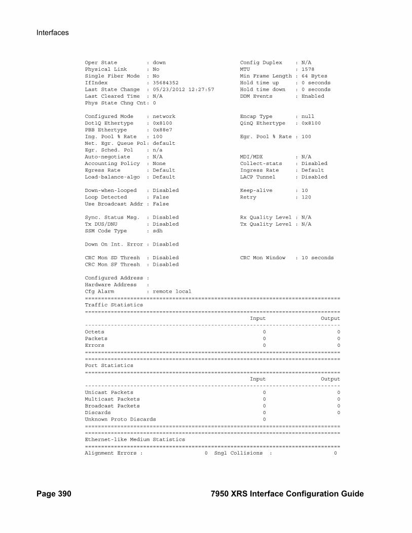
Interfaces
Page 390 7950 XRS Interface Configuration Guide
Oper State : down Config Duplex : N/APhysical Link : No MTU : 1578Single Fiber Mode : No Min Frame Length : 64 BytesIfIndex : 35684352 Hold time up : 0 secondsLast State Change : 05/23/2012 12:27:57 Hold time down : 0 secondsLast Cleared Time : N/A DDM Events : EnabledPhys State Chng Cnt: 0
Configured Mode : network Encap Type : nullDot1Q Ethertype : 0x8100 QinQ Ethertype : 0x8100PBB Ethertype : 0x88e7Ing. Pool % Rate : 100 Egr. Pool % Rate : 100Net. Egr. Queue Pol: defaultEgr. Sched. Pol : n/aAuto-negotiate : N/A MDI/MDX : N/AAccounting Policy : None Collect-stats : DisabledEgress Rate : Default Ingress Rate : DefaultLoad-balance-algo : Default LACP Tunnel : Disabled
Down-when-looped : Disabled Keep-alive : 10Loop Detected : False Retry : 120Use Broadcast Addr : False
Sync. Status Msg. : Disabled Rx Quality Level : N/ATx DUS/DNU : Disabled Tx Quality Level : N/ASSM Code Type : sdh
Down On Int. Error : Disabled
CRC Mon SD Thresh : Disabled CRC Mon Window : 10 secondsCRC Mon SF Thresh : Disabled
Configured Address :Hardware Address :Cfg Alarm : remote local===============================================================================Traffic Statistics=============================================================================== Input Output-------------------------------------------------------------------------------Octets 0 0Packets 0 0Errors 0 0==============================================================================================================================================================Port Statistics=============================================================================== Input Output-------------------------------------------------------------------------------Unicast Packets 0 0Multicast Packets 0 0Broadcast Packets 0 0Discards 0 0Unknown Proto Discards 0==============================================================================================================================================================Ethernet-like Medium Statistics===============================================================================Alignment Errors : 0 Sngl Collisions : 0

Interface Configuration
7950 XRS Interface Configuration Guide Page 391
FCS Errors : 0 Mult Collisions : 0SQE Test Errors : 0 Late Collisions : 0CSE : 0 Excess Collisns : 0Too long Frames : 0 Int MAC Tx Errs : 0Symbol Errors : 0 Int MAC Rx Errs : 0In Pause Frames : 0 Out Pause Frames : 0===============================================================================
Entering port ranges:
*A:ALU-1# configure port 1/1/[1..3] shut *A:ALU-1# show port 1/1 ==============================================================================Ports on Slot 1==============================================================================Port Admin Link Port Cfg Oper LAG/ Port Port Port SFP/XFP/ Id State State MTU MTU Bndl Mode Encp Type MDIMDX ------------------------------------------------------------------------------1/1/1 Down No Down 1518 1518 1 accs dotq gige 1/1/2 Down No Down 1578 1578 - netw null gige 1/1/3 Down No Down 1578 1578 - netw null gige 1/1/4 Up No Down 1514 1514 - accs null gige 1/1/5 Up No Down 1578 1578 - netw null gige ==============================================================================*A:ALU-1#
Specific Port Output Fields Specific Port Output — The following table describes port output fields for a specific port.
Label Description
Description A text description of the port.
Interface The port ID displayed in the slot/mda/port format.
Speed The speed of the interface.
Link-level Ethernet — The port is configured as Ethernet.
MTU The size of the largest packet which can be sent/received on the Ethernet physical interface, specified in octets.
Admin State Up — The port is administratively up.
Down — The port is administratively down.
Oper State Up — The port is operationally up.
Down — The port is operationally down.
Additionally, the lag-id of the LAG it belongs to in addition to the status of the LAG member (active or standby) is specified.
Duplex Full — The link is set to full duplex mode.
Half — The link is set to half duplex mode.

Interfaces
Page 392 7950 XRS Interface Configuration Guide
Hold time up The link up dampening time in seconds. The port link dampening timer value which reduces the number of link transitions reported to upper layer protocols.
Hold time down The link down dampening time in seconds. The down timer controls the dampening timer for link down transitions.
Physical Link Yes — A physical link is present.
No — A physical link is not present.
IfIndex Displays the interface's index number which reflects its initialization sequence.
Last State chg Displays the system time moment that the peer is up.
Last State Change
Displays the system time moment that the MC-LAG group is up.
Phys State Chng Cnt
Increments when a fully qualified (de-bounced) transition occurs at the physical layer of an ethernet port which includes the following transitions of the Port State as shown in the “show port” summary:- from “Down” to either “Link Up” or “Up”- from either “Link Up” or “Up” to “Down”This counter does not increment for changes purely in the link protocol states (e.g. "Link Up" to "Up"). The counter is reset if the container objects for the port are deleted (e.g. MDA deconfigured, or IOM type changes).
Last Cleared Time
Displays the system time moment that the peer is up.
DDM Events Enabled — DDM events are enabledDisabled — DDM events are disabled
Configured Mode network — The port is configured for transport network use.
access — The port is configured for service access.
Dot1Q Ethertype Indicates the Ethertype expected when the port's encapsulation type is Dot1Q.
QinQ Ethertype Indicates the Ethertype expected when the port's encapsulation type is QinQ.
Net. Egr. Queue Pol
Specifies the network egress queue policy or that the default policy is used.
Encap Type Null — Ingress frames will not use any tags or labels to delineate a service.
dot1q — Ingress frames carry 802.1Q tags where each tag signifies a different service.
Active Alarms The number of alarms outstanding on this port.
Label Description (Continued)

Interface Configuration
7950 XRS Interface Configuration Guide Page 393
Auto-negotiate True — The link attempts to automatically negotiate the link speed and duplex parameters.
False — The duplex and speed values are used for the link.
Alarm State The current alarm state of the port.
Collect Stats Enabled — The collection of accounting and statistical data for the network Ethernet port is enabled. When applying accounting policies the data by default will be collected in the appropriate records and written to the designated billing file.
Disabled — Collection is disabled. Statistics are still accumulated by the IOM cards, however, the CPU will not obtain the results and write them to the billing file.
Egress Rate The maximum amount of egress bandwidth (in kilobits per second) that this Ethernet interface can generate.
Egress Buf (Acc) The access-buffer policy for the egress buffer.
Egress Buf (Net) The network-buffer policy for the egress buffer.
Egress Pool Size The amount of egress buffer space, expressed as a percentage of the available buffer space that will be allocated to the port or channel for egress buffering.
Ingress Buf (Acc)
The access-buffer policy for the ingress buffer.
Ingress Pool Size
The amount of ingress buffer space, expressed as a percentage of the available buffer space that will be allocated to the port or channel for ingress buffering.
Configured Address
The base chassis Ethernet MAC address.
Hardware Address The interface's hardware or system assigned MAC address at itsprotocol sub-layer.
Transceiver Type Type of the transceiver.
Model Number The model number of the transceiver.
Transceiver Code The code for the transmission media.
Laser Wavelength The light wavelength transmitted by the transceiver's laser.
Connector Code The vendor organizationally unique identifier field (OUI)contains the IEEE company identifier for the vendor.
Diag Capable Indicates if the transceiver is capable of doing diagnostics.
Label Description (Continued)

Interfaces
Page 394 7950 XRS Interface Configuration Guide
Vendor OUI The vendor-specific identifier field (OUI) contains the IEEE company identifier for the vendor.
Manufacture date The manufacturing date of the hardware component in the mmddyyyy ASCII format.
Media The media supported for the SFP.
Serial Number The vendor serial number of the hardware component.
Part Number The vendor part number contains ASCII characters, defining the vendor part number or product name.
Input/Output When the collection of accounting and statistical data is enabled, then octet, packet, and error statistics are displayed.
Description A text description of the port.
Interface The port ID displayed in the slot/mda/port format.
Speed The speed of the interface
Link-level Ethernet — The port is configured as Ethernet.
MTU The size of the largest packet which can be sent/received on the Ethernet physical interface, specified in octets.
Admin State Up — The port is administratively up.
Down — The port is administratively down.
Oper State Up — The port is operationally up.
Down — The port is operationally down.
Duplex Full — The link is set to full duplex mode.
Half — The link is set to half duplex mode.
Hold time up The link up dampening time in seconds. The port link dampening timer value which reduces the number of link transitions reported to upper layer protocols.
Hold time down The link down dampening time in seconds. The down timer controls the dampening timer for link down transitions.
IfIndex Displays the interface's index number which reflects its initialization sequence.
Phy Link Yes — A physical link is present.
No — A physical link is not present.
Configured Mode network — The port is configured for transport network use.
Label Description (Continued)

Interface Configuration
7950 XRS Interface Configuration Guide Page 395
access — The port is configured for service access.
Network Qos Pol The network QoS policy ID applied to the port.
Encap Type Null — Ingress frames will not use any tags or labels to delineate a service.
dot1q — Ingress frames carry 802.1Q tags where each tag signifies a different service.
Active Alarms The number of alarms outstanding on this port.
Auto-negotiate True — The link attempts to automatically negotiate the link speed and duplex parameters.
False — The duplex and speed values are used for the link.
Alarm State The current alarm state of the port.
Collect Stats Enabled — The collection of accounting and statistical data for the network Ethernet port is enabled. When applying accounting policies the data by default will be collected in the appropriate records and written to the designated billing file.
Disabled — Collection is disabled. Statistics are still accumulated by the IOM cards, however, the CPU will not obtain the results and write them to the billing file.
Down-When-Looped Shows whether the feature is enabled or disabled.
Egress Buf (Acc) The access-buffer policy for the egress buffer.
Egress Buf (Net) The network-buffer policy for the egress buffer.
Ingress Buf (Acc)
The access-buffer policy for the ingress buffer.
Ingress Pool Size
The amount of ingress buffer space, expressed as a percentage of the available buffer space, that will be allocated to the port or channel for ingress buffering.
Configured Address
The base chassis Ethernet MAC address.
Hardware Address The interface's hardware or system assigned MAC address at itsprotocol sub-layer.
Label Description (Continued)

Interfaces
Page 396 7950 XRS Interface Configuration Guide
Errors Input/Output
For packet-oriented interfaces, the number of inbound packets that contained errors preventing them from being deliverable to a higher-layer protocol. For character-oriented or fixed-length interfaces, the number of inbound transmission units that contained errors preventing them from being deliverable to a higher-layer protocol.For packet-oriented interfaces, the number of outbound packets that could not be transmitted because of errors. For character-oriented or fixed-length interfaces, the number of outbound transmission units that could not be transmitted because of errors.
Unicast Packets Input/Output
The number of packets, delivered by this sub-layer to a higher (sub-) layer, which were not addressed to a multicast or broadcast address at this sub-layer. The total number of packets that higher-level protocols requested be transmitted, and which were not addressed to a multicast or broadcast address at this sub-layer, including those that were discarded or not sent.
Multicast Pack-ets Input/Output
The number of packets, delivered by this sub-layer to a higher (sub-) layer, which were addressed to a multicast address at this sub-layer. For a MAC layer protocol, this includes both group and functional addresses. The total number of packets that higher-level protocols requested be transmitted, and which were addressed to a multicast address at this sub-layer, including those that were discarded or not sent. For a MAC layer protocol, this includes both Group and Functional addresses.
Broadcast Pack-ets Input/Output
The number of packets, delivered by this sub-layer to a higher (sub-) layer, which were addressed to a broadcast address at this sub-layer. The total number of packets that higher-level protocols requested be transmitted, and which were addressed to a multicast address at this sub-layer, including those that were discarded or not sent. For a MAC layer protocol, this includes both Group and Functional addresses.
Discards Input/Output
The number of inbound packets chosen to be discarded to possibly free up buffer space.
Unknown Proto Discards Input/Output
For packet-oriented interfaces, the number of packets received through the interface which were discarded because of an unknown or unsupported protocol. For character-oriented or fixed-length interfaces that support protocol multiplexing the number of transmission units received via the interface which were discarded because of an unknown or unsupported protocol. For any interface that does not support protocol multiplexing, this counter will always be 0. For ATM, this field displays cells discarded on an invalid vpi/vci. Unknown proto discards do not show up in the packet counts.
Errors This field displays the number of cells discarded due to uncorrectable HEC errors. Errors do not show up in the raw cell counts.
Sync. Status Msg Whether synchronization status messages are enabled or disabled.
Label Description (Continued)

Interface Configuration
7950 XRS Interface Configuration Guide Page 397
Tx DUS/DNU Whether the QL value is forcibly set to QL-DUS/QL-DNU.
Rx Quality Level Indicates which QL value has been received from the interface.
Tx Quality Level Indicates which QL value is being transmitted out of the interface.
SSM Code Type Indicates the SSM code type in use on the port.
Label Description (Continued)

Interfaces
Page 398 7950 XRS Interface Configuration Guide
Detailed Port Output Fields Detailed Port Output — The following table describes detailed port output fields.
Label Description
Description A text description of the port.
Interface The port ID displayed in the slot/mda/port format.
Speed The speed of the interface.
Link-level Ethernet — The port is configured as Ethernet.
MTU The size of the largest packet which can be sent/received on the Ethernet physical interface, specified in octets.
Admin State Up — The port is administratively up.
Down — The port is administratively down.
Oper State Up — The port is operationally up.
Down — The port is operationally down.
Duplex Full — The link is set to full duplex mode.
Half — The link is set to half duplex mode.
Hold time up The link up dampening time in seconds. The port link dampening timer value which reduces the number of link transitions reported to upper layer protocols.
Hold time down The link down dampening time in seconds. The down timer controls the dampening timer for link down transitions.
IfIndex Displays the interface's index number which reflects its initialization sequence.
Phy Link Yes — A physical link is present.
No — A physical link is not present.
Phys State Chng Cnt
Increments when a fully qualified (de-bounced) transition occurs at the physical layer of an ethernet port which includes the following transitions of the Port State as shown in the “show port” summary:- from “Down” to either “Link Up” or “Up”- from either “Link Up” or “Up” to “Down”This counter does not increment for changes purely in the link protocol states (e.g. "Link Up" to "Up"). The counter is reset if the container objects for the port are deleted (e.g. MDA deconfigured, or IOM type changes).
Last Cleared Time
Displays the system time moment that the peer is up.

Interface Configuration
7950 XRS Interface Configuration Guide Page 399
DDM Events Enabled — DDM events are enabledDisabled — DDM events are disabled
Configured Mode network — The port is configured for transport network use.
access — The port is configured for service access.
Network Qos Pol The QoS policy ID applied to the port.
Access Egr. Qos Specifies the access egress policy or that the default policy 1 is in use.
Egr. Sched. Pol Specifies the port scheduler policy or that the default policy default is in use.
Encap Type Null — Ingress frames will not use any tags or labels to delineate a service.
dot1q — Ingress frames carry 802.1Q tags where each tag signifies a different service.
Active Alarms The number of alarms outstanding on this port.
Auto-negotiate True — The link attempts to automatically negotiate the link speed and duplex parameters.
False — The duplex and speed values are used for the link.
Alarm State The current alarm state of the port.
Collect Stats Enabled — The collection of accounting and statistical data for the network Ethernet port is enabled. When applying accounting policies the data by default will be collected in the appropriate records and written to the designated billing file.
Disabled — Collection is disabled. Statistics are still accumulated by the IOM cards, however, the CPU will not obtain the results and write them to the billing file.
Down-When-Looped Shows whether the feature is enabled or disabled.
Egress Rate The maximum amount of egress bandwidth (in kilobits per second) that this Ethernet interface can generate.
Egress Buf (Acc) The access-buffer policy for the egress buffer.
Egress Buf (Net) The network-buffer policy for the egress buffer.
Egress Pool Size The amount of egress buffer space, expressed as a percentage of the available buffer space that will be allocated to the port or channel for egress buffering.
Ingress Buf (Acc)
The access-buffer policy for the ingress buffer.
Label Description (Continued)

Interfaces
Page 400 7950 XRS Interface Configuration Guide
Ingress Pool Size
The amount of ingress buffer space, expressed as a percentage of the available buffer space, that will be allocated to the port or channel for ingress buffering.
Configured Address
The base chassis Ethernet MAC address.
Hardware Address The interface's hardware or system assigned MAC address at itsprotocol sub-layer.
Errors Input/Output
For packet-oriented interfaces, the number of inbound packets that contained errors preventing them from being deliverable to a higher-layer protocol. For character-oriented or fixed-length interfaces, the number of inbound transmission units that contained errors preventing them from being deliverable to a higher-layer protocol.For packet-oriented interfaces, the number of outbound packets that could not be transmitted because of errors. For character-oriented or fixed-length interfaces, the number of outbound transmission units that could not be transmitted because of errors.
Unicast Packets Input/Output
The number of packets, delivered by this sub-layer to a higher (sub-) layer, which were not addressed to a multicast or broadcast address at this sub-layer. The total number of packets that higher-level protocols requested be transmitted, and which were not addressed to a multicast or broadcast address at this sub-layer, including those that were discarded or not sent.
Multicast Pack-ets Input/Output
The number of packets, delivered by this sub-layer to a higher (sub-) layer, which were addressed to a multicast address at this sub-layer. For a MAC layer protocol, this includes both Group and Functional addresses. The total number of packets that higher-level protocols requested be transmitted, and which were addressed to a multicast address at this sub-layer, including those that were discarded or not sent. For a MAC layer protocol, this includes both Group and Functional addresses.
Broadcast Pack-ets Input/Output
The number of packets, delivered by this sub-layer to a higher (sub-) layer, which were addressed to a broadcast address at this sub-layer. The total number of packets that higher-level protocols requested be transmitted, and which were addressed to a multicast address at this sub-layer, including those that were discarded or not sent. For a MAC layer protocol, this includes both Group and Functional addresses.
Discards Input/Output
The number of inbound packets chosen to be discarded to possibly free up buffer space.
Label Description (Continued)
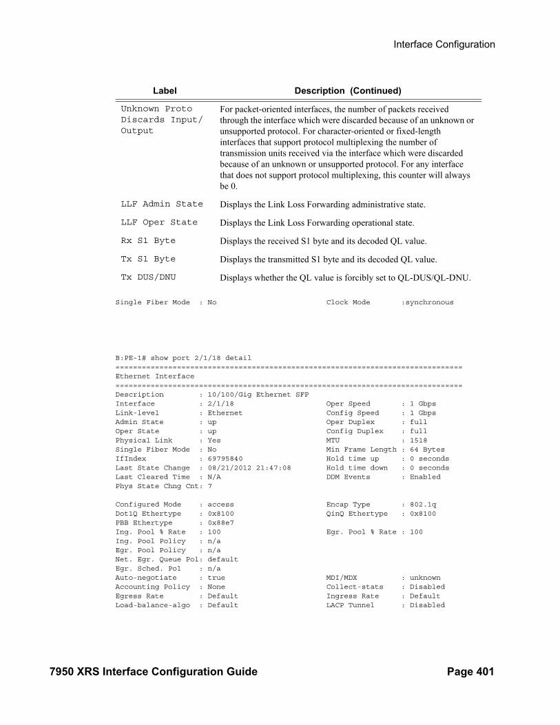
Interface Configuration
7950 XRS Interface Configuration Guide Page 401
Single Fiber Mode : No Clock Mode :synchronous
B:PE-1# show port 2/1/18 detail ===============================================================================Ethernet Interface===============================================================================Description : 10/100/Gig Ethernet SFPInterface : 2/1/18 Oper Speed : 1 GbpsLink-level : Ethernet Config Speed : 1 GbpsAdmin State : up Oper Duplex : fullOper State : up Config Duplex : fullPhysical Link : Yes MTU : 1518Single Fiber Mode : No Min Frame Length : 64 BytesIfIndex : 69795840 Hold time up : 0 secondsLast State Change : 08/21/2012 21:47:08 Hold time down : 0 secondsLast Cleared Time : N/A DDM Events : EnabledPhys State Chng Cnt: 7
Configured Mode : access Encap Type : 802.1qDot1Q Ethertype : 0x8100 QinQ Ethertype : 0x8100PBB Ethertype : 0x88e7 Ing. Pool % Rate : 100 Egr. Pool % Rate : 100Ing. Pool Policy : n/aEgr. Pool Policy : n/aNet. Egr. Queue Pol: default Egr. Sched. Pol : n/aAuto-negotiate : true MDI/MDX : unknownAccounting Policy : None Collect-stats : DisabledEgress Rate : Default Ingress Rate : DefaultLoad-balance-algo : Default LACP Tunnel : Disabled
Unknown Proto Discards Input/Output
For packet-oriented interfaces, the number of packets received through the interface which were discarded because of an unknown or unsupported protocol. For character-oriented or fixed-length interfaces that support protocol multiplexing the number of transmission units received via the interface which were discarded because of an unknown or unsupported protocol. For any interface that does not support protocol multiplexing, this counter will always be 0.
LLF Admin State Displays the Link Loss Forwarding administrative state.
LLF Oper State Displays the Link Loss Forwarding operational state.
Rx S1 Byte Displays the received S1 byte and its decoded QL value.
Tx S1 Byte Displays the transmitted S1 byte and its decoded QL value.
Tx DUS/DNU Displays whether the QL value is forcibly set to QL-DUS/QL-DNU.
Label Description (Continued)

Interfaces
Page 402 7950 XRS Interface Configuration Guide
Down-when-looped : Disabled Keep-alive : 10Loop Detected : False Retry : 120Use Broadcast Addr : False
Sync. Status Msg. : Disabled Rx Quality Level : N/ATx DUS/DNU : Disabled Tx Quality Level : N/ASSM Code Type : sdh
Down On Int. Error : Disabled
CRC Mon SD Thresh : Disabled CRC Mon Window : 10 secondsCRC Mon SF Thresh : Disabled
Configured Address : 00:03:fa:1b:bb:3fHardware Address : 00:03:fa:1b:bb:3f
Transceiver Data Transceiver Type : SFPModel Number : 3HE00027AAAA02 ALA IPUIAELDABTX Laser Wavelength: 850 nm Diag Capable : yesConnector Code : LC Vendor OUI : 00:90:65Manufacture date : 2008/09/25 Media : EthernetSerial Number : PED38UH Part Number : FTRJ8519P2BNL-A5Optical Compliance : GIGE-SX Link Length support: 300m for OM2 50u MMF; 150m for OM1 62.5u MMF===============================================================================Transceiver Digital Diagnostic Monitoring (DDM), Internally Calibrated=============================================================================== Value High Alarm High Warn Low Warn Low Alarm-------------------------------------------------------------------------------Temperature (C) +25.9 +95.0 +90.0 -20.0 -25.0 Supply Voltage (V) 3.32 3.90 3.70 2.90 2.70 Tx Bias Current (mA) 8.1 17.0 14.0 2.0 1.0 Tx Output Power (dBm) -4.49 -2.00 -2.00 -11.02 -11.74 Rx Optical Power (avg dBm) -5.16 1.00 -1.00 -18.01 -20.00 ==============================================================================================================================================================Traffic Statistics=============================================================================== Input Output-------------------------------------------------------------------------------Octets 0 0Packets 0 0Errors 0 0===============================================================================Ethernet Statistics===============================================================================Broadcast Pckts : 0 Drop Events : 0Multicast Pckts : 0 CRC/Align Errors : 0Undersize Pckts : 0 Fragments : 0Oversize Pckts : 0 Jabbers : 0Collisions : 0
Octets : 0Packets : 0Packets of 64 Octets : 0Packets of 65 to 127 Octets : 0

Interface Configuration
7950 XRS Interface Configuration Guide Page 403
Packets of 128 to 255 Octets : 0Packets of 256 to 511 Octets : 0Packets of 512 to 1023 Octets : 0Packets of 1024 to 1518 Octets : 0Packets of 1519 or more Octets : 0==============================================================================================================================================================Port Statistics=============================================================================== Input Output-------------------------------------------------------------------------------Unicast Packets 0 0Multicast Packets 0 0Broadcast Packets 0 0Discards 0 0Unknown Proto Discards 0 ==============================================================================================================================================================Ethernet-like Medium Statistics===============================================================================Alignment Errors : 0 Sngl Collisions : 0FCS Errors : 0 Mult Collisions : 0SQE Test Errors : 0 Late Collisions : 0CSE : 0 Excess Collisns : 0Too long Frames : 0 Int MAC Tx Errs : 0Symbol Errors : 0 Int MAC Rx Errs : 0In Pause Frames : 0 Out Pause Frames : 0==============================================================================================================================================================Per Threshold MDA Discard Statistics=============================================================================== Packets Octets-------------------------------------------------------------------------------Threshold 0 Dropped : 0 0 Threshold 1 Dropped : 0 0 Threshold 2 Dropped : 0 0 Threshold 3 Dropped : 0 0 Threshold 4 Dropped : 0 0 Threshold 5 Dropped : 0 0 Threshold 6 Dropped : 0 0 Threshold 7 Dropped : 0 0 Threshold 8 Dropped : 0 0 Threshold 9 Dropped : 0 0 Threshold 10 Dropped : 0 0 Threshold 11 Dropped : 0 0 Threshold 12 Dropped : 0 0 Threshold 13 Dropped : 0 0 Threshold 14 Dropped : 0 0 Threshold 15 Dropped : 0 0 ===============================================================================B:PE-1#
show port 1/1/1 vport "abc" monitor-thresh-old===============================================================================Port 1/1/1 Vport "abc" Monitor Threshold Info

Interfaces
Page 404 7950 XRS Interface Configuration Guide
===============================================================================Attribute Exceed Count Config Rate Threshold Prcnt-------------------------------------------------------------------------------Agg-Eps 0 212 32Lvl-1 0 12323 89Lvl-2 0 32132 32Lvl-5 0 2323 4Grp-01234567890123458746513513355656 0 2121 12-------------------------------------------------------------------------------Start Time : 01/07/2015 16:53:16 End Time : 01/07/2015 16:53:36Total Samples : ===============================================================================
Note: If the Vport name is omitted, statistics for all Vports would be displayed (bulk read). The statistics are displayed only for the levels, groups and agg-eps for which the monitor-threshold is enabled. The output information filtering per level, group or agg-eps is not embedded in the show commands natively. Instead the output can be filtered with the match extensions for the show command. For example, show port 1/1/1 vport test monitor-threshold | match Lvl-1.
*A:sne# show port 1/1/4 vport statistics===============================================================================Port 1/1/4 Access Egress vport===============================================================================VPort Name : vp1Description : (Not Specified)Sched Policy : portschedpol1Rate Limit : MaxRate Modify : disabledModify delta : 0Vport Queueing Statistics
Last Cleared Time : N/A Packets OctetsForwarded: 0 0Dropped : 0 0-------------------------------------------------------------------------------Vport per Level Queueing Statistics Packets OctetsLevel : 8Forwarded: 0 0Dropped : 0 0Level : 7Forwarded: 0 0Dropped : 0 0Level : 6Forwarded: 0 0Dropped : 0 0Level : 5Forwarded: 0 0Dropped : 0 0Level : 4Forwarded: 0 0Dropped : 0 0Level : 3Forwarded: 0 0Dropped : 0 0

Interface Configuration
7950 XRS Interface Configuration Guide Page 405
Level : 2Forwarded: 0 0Dropped : 0 0Level : 1Forwarded: 0 0Dropped : 0 0
Host-Matches-------------------------------------------------------------------------------Dest: dslam1-------------------------------------------------------------------------------===============================================================================*A:sne#
Ethernet Output — The following table describes the output fields.
Label Description
Broadcast Pckts The number of packets, delivered by this sub-layer to a higher (sub-) layer, which were addressed to a broadcast address at this sub-layer. The total number of packets that higher-level protocols requested be transmitted, and which were addressed to a multicast address at this sub-layer, including those that were discarded or not sent. For a MAC layer protocol, this includes both Group and Functional addresses.
Multicast Pckets The number of packets, delivered by this sub-layer to a higher (sub-) layer, which were addressed to a multicast address at this sub-layer. For a MAC layer protocol, this includes both Group and Functional addresses. The total number of packets that higher-level protocols requested be transmitted, and which were addressed to a multicast address at this sub-layer, including those that were discarded or not sent. For a MAC layer protocol, this includes both Group and Functional addresses.
Undersize Pckets The total number of packets received that were less than 64 octets long (excluding framing bits, but including FCS octets) and were otherwise well formed.
Oversize Pckts The total number of packets received that were longer than can be accepted by the physical layer of that port (9900 octets excluding framing bits, but including FCS octets for GE ports) and were otherwise well formed.
Collisions The best estimate of the total number of collisions on this Ethernet segment.
Drop Events The total number of events in which packets were dropped by the probe due to lack of resources. Note that this number is not necessarily the number of packets dropped; it is just the number of times this condition has been detected.
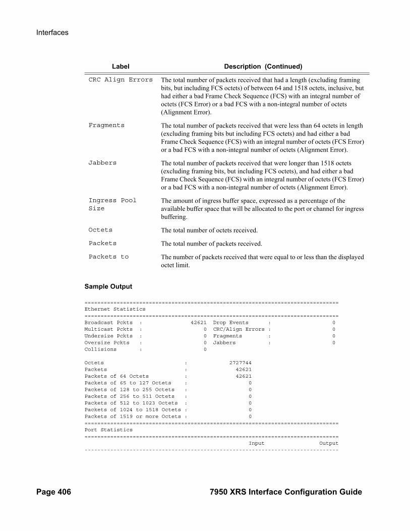
Interfaces
Page 406 7950 XRS Interface Configuration Guide
Sample Output
===============================================================================Ethernet Statistics===============================================================================Broadcast Pckts : 42621 Drop Events : 0Multicast Pckts : 0 CRC/Align Errors : 0Undersize Pckts : 0 Fragments : 0Oversize Pckts : 0 Jabbers : 0Collisions : 0
Octets : 2727744Packets : 42621Packets of 64 Octets : 42621Packets of 65 to 127 Octets : 0Packets of 128 to 255 Octets : 0Packets of 256 to 511 Octets : 0Packets of 512 to 1023 Octets : 0Packets of 1024 to 1518 Octets : 0Packets of 1519 or more Octets : 0===============================================================================Port Statistics=============================================================================== Input Output-------------------------------------------------------------------------------
CRC Align Errors The total number of packets received that had a length (excluding framing bits, but including FCS octets) of between 64 and 1518 octets, inclusive, but had either a bad Frame Check Sequence (FCS) with an integral number of octets (FCS Error) or a bad FCS with a non-integral number of octets (Alignment Error).
Fragments The total number of packets received that were less than 64 octets in length (excluding framing bits but including FCS octets) and had either a bad Frame Check Sequence (FCS) with an integral number of octets (FCS Error) or a bad FCS with a non-integral number of octets (Alignment Error).
Jabbers The total number of packets received that were longer than 1518 octets (excluding framing bits, but including FCS octets), and had either a bad Frame Check Sequence (FCS) with an integral number of octets (FCS Error) or a bad FCS with a non-integral number of octets (Alignment Error).
Ingress Pool Size
The amount of ingress buffer space, expressed as a percentage of the available buffer space that will be allocated to the port or channel for ingress buffering.
Octets The total number of octets received.
Packets The total number of packets received.
Packets to The number of packets received that were equal to or less than the displayed octet limit.
Label Description (Continued)

Interface Configuration
7950 XRS Interface Configuration Guide Page 407
Unicast Packets 0 0Multicast Packets 0 0Broadcast Packets 42621 0Discards 0 0Unknown Proto Discards 0===============================================================================...
Ethernet-Like Medium Statistics Output Fields Ethernet-like Medium Statistics Output — The following table describes Ethernet-like medium statistics output fields.
Label Description
Alignment Errors The total number of packets received that had a length (excluding framing bits, but including FCS octets) of between 64 and 1518 octets, inclusive, but had either a bad Frame Check Sequence (FCS) with an integral number of octets (FCS Error) or a bad FCS with a non-integral number of octets.
FCS Errors The number of frames received on a particular interface that are an integral number of octets in length but do not pass the FCS check.
SQE Errors The number of times that the SQE TEST ERROR is received on a particular interface.
CSE The number of times that the carrier sense condition was lost or never asserted when attempting to transmit a frame on a particular interface.
Too long Frames The number of frames received on a particular interface that exceed the maximum permitted frame size.
Symbol Errors For an interface operating at 100 Mb/s, the number of times there was an invalid data symbol when a valid carrier was present.
Sngl Collisions The number of frames that are involved in a single collision, and are subsequently transmitted successfully.
Mult Collisions The number of frames that are involved in more than one collision and are subsequently transmitted successfully.
Late Collisions The number of times that a collision is detected on a particular interface later than one slotTime into the transmission of a packet.
Excess Collisns The number of frames for which transmission on a particular interface fails due to excessive collisions.
Int MAC Tx Errs The number of frames for which transmission on a particular interface fails due to an internal MAC sublayer transmit error,
Int MAC Rx Errs The number of frames for which reception on a particular interface fails due to an internal MAC sublayer receive error.

Interfaces
Page 408 7950 XRS Interface Configuration Guide
Sample Output
A:ALA-48# show port 1/3/1 detail===============================================================================...===============================================================================Ethernet-like Medium Statistics===============================================================================Alignment Errors : 0 Sngl Collisions : 0FCS Errors : 0 Mult Collisions : 0SQE Test Errors : 0 Late Collisions : 0CSE : 0 Excess Collisns : 0Too long Frames : 0 Int MAC Tx Errs : 0Symbol Errors : 0 Int MAC Rx Errs : 0Queue Statistics===============================================================================Ingress Queue 1 Packets Octets In Profile forwarded : 0 0 In Profile dropped : 0 0 Out Profile forwarded : 0 0 Out Profile dropped : 0 0Ingress Queue 2 Packets Octets In Profile forwarded : 0 0 In Profile dropped : 0 0 Out Profile forwarded : 0 0 Out Profile dropped : 0 0Ingress Queue 3 Packets Octets In Profile forwarded : 0 0 In Profile dropped : 0 0 Out Profile forwarded : 0 0 Out Profile dropped : 0 0Ingress Queue 4 Packets Octets In Profile forwarded : 0 0 In Profile dropped : 0 0 Out Profile forwarded : 0 0 Out Profile dropped : 0 0Ingress Queue 5 Packets Octets In Profile forwarded : 0 0 In Profile dropped : 0 0 Out Profile forwarded : 0 0 Out Profile dropped : 0 0Ingress Queue 6 Packets Octets In Profile forwarded : 0 0 In Profile dropped : 0 0 Out Profile forwarded : 0 0 Out Profile dropped : 0 0============================================================================================================================================================== Per Threshold MDA Discard Statistics =============================================================================== Packets Octets------------------------------------------------------------------------------- Threshold 0 Dropped : 0 0 Threshold 1 Dropped : 0 0 Threshold 2 Dropped : 0 0 Threshold 3 Dropped : 0 0 Threshold 4 Dropped : 0 0 Threshold 5 Dropped : 0 0

Interface Configuration
7950 XRS Interface Configuration Guide Page 409
Threshold 6 Dropped : 0 0 Threshold 7 Dropped : 0 0 Threshold 8 Dropped : 0 0 Threshold 9 Dropped : 0 0 Threshold 10 Dropped : 0 0 Threshold 11 Dropped : 0 0 Threshold 12 Dropped : 0 0 Threshold 13 Dropped : 0 0 Threshold 14 Dropped : 0 0 Threshold 15 Dropped : 0 0 ===============================================================================A:ALA-48#

Interfaces
Page 410 7950 XRS Interface Configuration Guide
Port Associations Output Fields Port Associations Output — The following table describes port associations output fields.
Sample Output
A:ALA-1# show port 1/1/6 associations==============================================================================Interface Table==============================================================================Router/ServiceId Name Encap Val------------------------------------------------------------------------------Router: Base if1000 1000Router: Base if2000 2000------------------------------------------------------------------------------Interfaces==============================================================================A;ALA-1#
Port Frame Relay Output — The following table describes port Frame Relay output fields.
Sample Output
A:ALA-49>config>port# show port 8/1/2 frame-relay===============================================================================Frame Relay Info for 8/1/2===============================================================================Mode : dte LMI Type : ituFR Interface Status : faultN391 DTE : 6 N392 DCE : 3N392 DTE : 3 N393 DCE : 4N393 DTE : 4 T392 DCE : 15T391 DTE : 10
Label Description
Svc ID The service identifier.
Name The name of the IP interface.
Encap Value The dot1q or qinq encapsulation value on the port for this IP interface
Label Description
Mode Displays the mode of the interface. It can be set as Data terminal equipment (dte) or Data circuit-terminating equipment (DCE).
LMI Type Displays the LMI type.
FR Interface Status
Displays the status of the Frame Relay interface as determined by the performance of the dlcmi. If no DLCMI is running, the Frame Relay interface will stay in the running state indefinitely.

Interface Configuration
7950 XRS Interface Configuration Guide Page 411
Tx Status Enquiry : 0 Rx Status Enquiry : 0Rx Status Messages : 0 Tx Status Messages : 0Status Message Timeouts : 0 Status Enquiry Timeouts : 0Discarded Messages : 0 Inv. RxSeqNum Messages : 0===============================================================================A:ALA-49>config>port#
Sample Output
*A:PE>config>port>ethernet>dot1x# show port 1/1/5 dot1x ===============================================================================802.1x Port Status===============================================================================
Port control : autoPort status : authorizedAuthenticator PAE state : authenticatedBackend state : idleReauth enabled : no Reauth period : N/AMax auth requests : 2 Transmit period : 30 Supplicant timeout : 30 Server timeout : 30 Quiet period : 60 Radius-plcy : testTunneling : false
===============================================================================802.1x Session Statistics===============================================================================
authentication method : remote-radiuslast session id : PAC-02228000-11B0A9BBlast session time : 00h00m06slast session username : user1last session term cause : N/Auser tx octets : 0 user tx frames : 0 user rx octets : 0 user rx frames : 0
*A:Dut-C>config>port>ethernet>dot1x# /show port 1/1/5 dot1x detail ===============================================================================802.1x Port Status===============================================================================
Port control : autoPort status : authorizedAuthenticator PAE state : authenticatedBackend state : idleReauth enabled : no Reauth period : N/AMax auth requests : 2 Transmit period : 30 Supplicant timeout : 30 Server timeout : 30 Quiet period : 60 Radius-plcy : testTunneling : false
===============================================================================

Interfaces
Page 412 7950 XRS Interface Configuration Guide
802.1x Session Statistics===============================================================================
authentication method : remote-radiuslast session id : PAC-02228000-11B0A9BBlast session time : 00h00m10slast session username : user1last session term cause : N/Auser tx octets : 0 user tx frames : 0 user rx octets : 0 user rx frames : 0
===============================================================================802.1x Authentication Statistics===============================================================================
tx frames : 22 rx frames : 14 tx req/id frames : 6 rx resp/id frames : 3 tx request frames : 3 rx response frames : 3 rx start frames : 4 rx logoff frames : 4 rx unknown frame type : 0 rx bad eap length : 0 rx last version : 1 rx last source mac : 00:01:02:17:23:22
===============================================================================802.1x Authentication Diagnostics ===============================================================================
Enters Connecting : 6 EapLogoffs While Connecting : 1 Logoffs While Connecting : 1 Success While Authenticating : 3 Timeouts While Authenticating : 0 Failures While Authenticating : 0 Reauths While Authenticating : 0 EapStarts While Authenticating : 0 EapLogoffs While Authenticating : 0 Reauths While Authenticated : 0 EapStarts While Authenticated : 0 EapLogoffs While Authenticated : 1 Backend Responses : 6 Backend Access Challenges : 3 Backend Requests To Supplicant : 3 Backend Access Challenges : 0 Backend Non Nak Responses : 0 Backend Auth Successes : 3 Backend Auth Failures : 0

Interface Configuration
7950 XRS Interface Configuration Guide Page 413
ethernet efm-oam
Syntax ethernet efm-oam
Context show>port
Description This command shows EFM-OAM port state information.
Sample Output
# config port 1/1/1 ethernet efm-oam ignore-efm-state# show port 1/1/1 ethernet efm-oam
===============================================================================Ethernet Oam (802.3ah)===============================================================================Admin State : downOper State : disabledMode : activePdu Size : 1518Config Revision : 0Function Support : LB Transmit Interval : 1000 msMultiplier : 5Hold Time : 0Tunneling : falseLoop Detected : false
No Peer Information Available
Loopback State : NoneLoopback Ignore Rx : IgnoreIgnore Efm State : true
# config port 1/1/1 ethernet efm-oam noignore-efm-state# show port 1/1/1 ethernet efm-oam
===============================================================================Ethernet Oam (802.3ah)===============================================================================Admin State : downOper State : disabledMode : activePdu Size : 1518Config Revision : 0Function Support : LB Transmit Interval : 1000 msMultiplier : 5Hold Time : 0Tunneling : falseLoop Detected : false
No Peer Information Available
Loopback State : NoneLoopback Ignore Rx : IgnoreIgnore Efm State : false
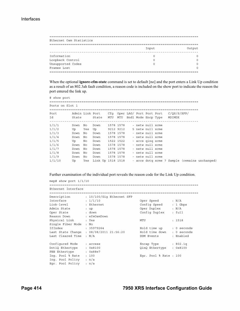
Interfaces
Page 414 7950 XRS Interface Configuration Guide
===============================================================================Ethernet Oam Statistics=============================================================================== Input Output-------------------------------------------------------------------------------Information 0 0Loopback Control 0 0Unsupported Codes 0 0Frames Lost 0===============================================================================
When the optional ignore-efm-state command is set to default [no] and the port enters a Link Up condition as a result of an 802.3ah fault condition, a reason code is included on the show port to indicate the reason the port entered the link up.
# show port===============================================================================Ports on Slot 1===============================================================================Port Admin Link Port Cfg Oper LAG/ Port Port Port C/QS/S/XFP/Id State State MTU MTU Bndl Mode Encp Type MDIMDX-------------------------------------------------------------------------------1/1/1 Down No Down 1578 1578 - netw null xcme1/1/2 Up Yes Up 9212 9212 5 netw null xcme1/1/3 Down No Down 1578 1578 - netw null xcme1/1/4 Down No Down 1578 1578 - netw null xcme1/1/5 Up No Down 1522 1522 - accs qinq xcme1/1/6 Down No Down 1578 1578 - netw null xcme1/1/7 Down No Down 1578 1578 - netw null xcme1/1/8 Down No Down 1578 1578 - netw null xcme1/1/9 Down No Down 1578 1578 - netw null xcme1/1/10 Up Yes Link Up 1518 1518 - accs dotq xcme ? Sample (remains unchanged)
Further examination of the individual port reveals the reason code for the Link Up condition.
mep# show port 1/1/10===============================================================================Ethernet Interface===============================================================================Description : 10/100/Gig Ethernet SFPInterface : 1/1/10 Oper Speed : N/ALink-level : Ethernet Config Speed : 1 GbpsAdmin State : up Oper Duplex : N/AOper State : down Config Duplex : fullReason Down : efmOamDownPhysical Link : Yes MTU : 1518Single Fiber Mode : NoIfIndex : 35979264 Hold time up : 0 secondsLast State Change : 08/08/2011 21:56:20 Hold time down : 0 secondsLast Cleared Time : N/A DDM Events : Enabled
Configured Mode : access Encap Type : 802.1qDot1Q Ethertype : 0x8100 QinQ Ethertype : 0x8100PBB Ethertype : 0x88e7Ing. Pool % Rate : 100 Egr. Pool % Rate : 100Ing. Pool Policy : n/aEgr. Pool Policy : n/a

Interface Configuration
7950 XRS Interface Configuration Guide Page 415
Net. Egr. Queue Pol: defaultEgr. Sched. Pol : n/aAuto-negotiate : true MDI/MDX : unknownAccounting Policy : None Collect-stats : DisabledEgress Rate : Default Ingress Rate : DefaultLoad-balance-algo : default LACP Tunnel : Disabled
Down-when-looped : Disabled Keep-alive : 10Loop Detected : False Retry : 120Use Broadcast Addr : False
Sync. Status Msg. : Disabled Rx Quality Level : N/ATx DUS/DNU : Disabled Tx Quality Level : N/ASSM Code Type : sdh
Configured Address : 90:f4:01:01:00:0aHardware Address : 90:f4:01:01:00:0aCfg Alarm :Alarm Status :===============================================================================
dot1x
Syntax dot1x [detail]
Context show>port>ethernet
Description This command displays 802.1x information.
Parameters detail — Displays detailed information.
Sample Output
*A:PE>config>port>ethernet>dot1x# show port 1/1/5 dot1x ===============================================================================802.1x Port Status===============================================================================
Port control : autoPort status : authorizedAuthenticator PAE state : authenticatedBackend state : idleReauth enabled : no Reauth period : N/AMax auth requests : 2 Transmit period : 30 Supplicant timeout : 30 Server timeout : 30 Quiet period : 60 Radius-plcy : testTunneling : false
===============================================================================802.1x Session Statistics===============================================================================
authentication method : remote-radiuslast session id : PAC-02228000-11B0A9BB
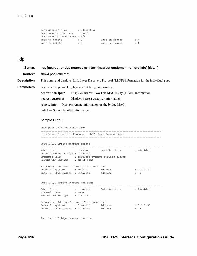
Interfaces
Page 416 7950 XRS Interface Configuration Guide
last session time : 00h00m06slast session username : user1last session term cause : N/Auser tx octets : 0 user tx frames : 0 user rx octets : 0 user rx frames : 0
lldp
Syntax lldp [nearest-bridge|nearest-non-tpmr|nearest-customer] [remote-info] [detail]
Context show>port>ethernet
Description This command displays Link Layer Discovery Protocol (LLDP) information for the individual port.
Parameters nearest-bridge — Displays nearest bridge information.
nearest-non-tpmr — Displays nearest Two-Port MAC Relay (TPMR) information.
nearest-customer — Displays nearest customer information.
remote-info — Displays remote information on the bridge MAC.
detail — Shows detailed information.
Sample Output
show port 1/1/1 ethernet lldp==============================================================================Link Layer Discovery Protocol (LLDP) Port Information==============================================================================
Port 1/1/1 Bridge nearest-bridge-------------------------------------------------------------------------------Admin State : txAndRx Notifications : DisabledTunnel Nearest Bridge : DisabledTransmit TLVs : portDesc sysName sysDesc sysCapPortID TLV Subtype : tx-if-name
Management Address Transmit Configuration:Index 1 (system) : Enabled Address : 1.1.1.31Index 2 (IPv6 system) : Disabled Address : ::
Port 1/1/1 Bridge nearest-non-tpmr-------------------------------------------------------------------------------Admin State : disabled Notifications : DisabledTransmit TLVs : NonePortID TLV Subtype : tx-local
Management Address Transmit Configuration:Index 1 (system) : Disabled Address : 1.1.1.31Index 2 (IPv6 system) : Disabled Address : ::
Port 1/1/1 Bridge nearest-customer

Interface Configuration
7950 XRS Interface Configuration Guide Page 417
-------------------------------------------------------------------------------Admin State : disabled Notifications : DisabledTransmit TLVs : NonePortID TLV Subtype : tx-local
Management Address Transmit Configuration:Index 1 (system) : Disabled Address : 1.1.1.31Index 2 (IPv6 system) : Disabled Address : ::
==============================================================================
show port 1/1/1 ethernet lldp remote-info==============================================================================Link Layer Discovery Protocol (LLDP) Port Information==============================================================================Port 1/1/1 Bridge nearest-bridge Remote Peer Information-------------------------------------------------------------------------------Remote Peer Index 9 at timestamp 12/08/2014 21:34:30:Supported Caps : bridge routerEnabled Caps : bridge routerChassis Id Subtype : 4 (macAddress)Chassis Id : D8:1C:FF:00:00:00PortId Subtype : 5 (interfaceName)Port Id : 31:2F:32:2F:32 "1/2/2"Port Description : n/aSystem Name : cses-V28System Description : TiMOS-B-0.0.I4269 both/i386 ALCATEL SR 7750 Copyright (c) 2000-2014 Alcatel-Lucent. All rights reserved. All use subject to applicable license agreements. Built on Wed Dec 3 19:14:27 PST 2014 by builder in / rel0.0/I4269/panos/main
Port 1/1/1 Bridge nearest-non-tpmr Remote Peer Information-------------------------------------------------------------------------------No remote peers found
Port 1/1/1 Bridge nearest-customer Remote Peer Information-------------------------------------------------------------------------------No remote peers found
==============================================================================
show port 1/1/1 ethernet lldp remote-info detail==============================================================================Link Layer Discovery Protocol (LLDP) Port Information==============================================================================Port 1/1/1 Bridge nearest-bridge Remote Peer Information-------------------------------------------------------------------------------Remote Peer Index 9 at timestamp 12/08/2014 21:34:30:Supported Caps : bridge routerEnabled Caps : bridge routerChassis Id Subtype : 4 (macAddress)Chassis Id : D8:1C:FF:00:00:00PortId Subtype : 5 (interfaceName)Port Id : 31:2F:32:2F:32

Interfaces
Page 418 7950 XRS Interface Configuration Guide
"1/2/2"Port Description : n/aSystem Name : cses-V28System Description : TiMOS-B-0.0.I4269 both/i386 ALCATEL SR 7750 Copyright (c) 2000-2014 Alcatel-Lucent. All rights reserved. All use subject to applicable license agreements. Built on Wed Dec 3 19:14:27 PST 2014 by builder in / rel0.0/I4269/panos/main
Remote Peer Index 9 management addresses at time 12/08/2014 21:34:30:Address SubType : 1 (IPv4)Address : 1.1.1.28Address If SubType : 2 Address If Id : 1Address OID : .1.3.6.1.4.1.6527.1.3.3
Port 1/1/1 Bridge nearest-non-tpmr Remote Peer Information-------------------------------------------------------------------------------No remote peers found
Port 1/1/1 Bridge nearest-customer Remote Peer Information-------------------------------------------------------------------------------No remote peers found
==============================================================================
show port 1/1/1 ethernet lldp detail==============================================================================Link Layer Discovery Protocol (LLDP) Port Information==============================================================================
Port 1/1/1 Bridge nearest-bridge-------------------------------------------------------------------------------Admin State : txAndRx Notifications : DisabledTunnel Nearest Bridge : DisabledTransmit TLVs : portDesc sysName sysDesc sysCapPortID TLV Subtype : tx-if-name
Management Address Transmit Configuration:Index 1 (system) : Enabled Address : 1.1.1.31Index 2 (IPv6 system) : Disabled Address : ::
Port LLDP Stats:Tx Frames : 11749 Tx Length Err Frames : 0Rx Frames : 70399 Rx Frame Discard : 0Rx Frame Errors : 0 Rx TLV Discard : 0Rx TLV Unknown : 0 Rx Ageouts : 3
Port 1/1/1 Bridge nearest-non-tpmr-------------------------------------------------------------------------------Admin State : disabled Notifications : DisabledTransmit TLVs : NonePortID TLV Subtype : tx-local
Management Address Transmit Configuration:Index 1 (system) : Disabled Address : 1.1.1.31

Interface Configuration
7950 XRS Interface Configuration Guide Page 419
Index 2 (IPv6 system) : Disabled Address : ::
Port LLDP Stats:Tx Frames : 0 Tx Length Err Frames : 0Rx Frames : 0 Rx Frame Discard : 0Rx Frame Errors : 0 Rx TLV Discard : 0Rx TLV Unknown : 0 Rx Ageouts : 0
Port 1/1/1 Bridge nearest-customer-------------------------------------------------------------------------------Admin State : disabled Notifications : DisabledTransmit TLVs : NonePortID TLV Subtype : tx-local
Management Address Transmit Configuration:Index 1 (system) : Disabled Address : 1.1.1.31Index 2 (IPv6 system) : Disabled Address : ::
Port LLDP Stats:Tx Frames : 0 Tx Length Err Frames : 0Rx Frames : 0 Rx Frame Discard : 0Rx Frame Errors : 0 Rx TLV Discard : 0Rx TLV Unknown : 0 Rx Ageouts : 0
==============================================================================
port-tree
Syntax port-tree port-id
Context show
Description This command displays the treeWAN PHY mode (xgig wan) Ethernet ports.
Parameters port-id — Specifies the physical port ID.
Syntax port-id slot[/mda[/port]] orslot/mda/port[.channel]
MDA Values 1—2
Slot Values 1—10
Port Values 1 — 60 (depending on the MDA type)
Output Show Port Tree Output — The following table describes show port tree output fields.
Label Description
IfIndex Displays the interface's index number which reflects its initialization sequence.
type Specifies the type.
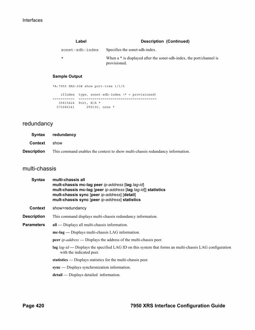
Interfaces
Page 420 7950 XRS Interface Configuration Guide
Sample Output
*A:7950 XRS-20# show port-tree 1/1/5
ifIndex type, sonet-sdh-index (* = provisioned)=========== ======================================= 35815424 Port, N/A * 572686341 STS192, none *
redundancy
Syntax redundancy
Context show
Description This command enables the context to show multi-chassis redundancy information.
multi-chassis
Syntax multi-chassis allmult-chassis mc-lag peer ip-address [lag lag-id]mult-chassis mc-lag [peer ip-address [lag lag-id]] statisticsmult-chassis sync [peer ip-address] [detail]mult-chassis sync [peer ip-address] statistics
Context show>redundancy
Description This command displays multi-chassis redundancy information.
Parameters all — Displays all multi-chassis information.
mc-lag — Displays multi-chassis LAG information.
peer ip-address — Displays the address of the multi-chassis peer.
lag lag-id — Displays the specified LAG ID on this system that forms an multi-chassis LAG configuration with the indicated peer.
statistics — Displays statistics for the multi-chassis peer.
sync — Displays synchronization information.
detail — Displays detailed information.
sonet-sdh-index Specifies the sonet-sdh-index.
* When a * is displayed after the sonet-sdh-index, the port/channel is provisioned.
Label Description (Continued)

Interface Configuration
7950 XRS Interface Configuration Guide Page 421
Sample Output
A:pc1# show redundancy multi-chassis all ===============================================================================Multi-Chassis Peers===============================================================================Peer IP Src IP Auth Peer Admin MCS Admin MCS Oper MCS State MC-LAG Admin MC-LAG Oper -------------------------------------------------------------------------------10.10.10.102 10.10.10.101 hash Enabled Enabled Enabled inSync Enabled Enabled 10.10.20.1 0.0.0.0 None Disabled -- -- -- Disabled Disabled ===============================================================================A:pc1#
*A:Dut-C# show redundancy multi-chassis mc-lag peer 10.10.10.1 ===============================================================================Multi-Chassis MC-Lag Peer 10.10.10.1===============================================================================Last State chg: 09/24/2007 07:58:03 Admin State: Up Oper State : Up KeepAlive: 10 deci-seconds Hold On Ngbr Failure : 3 -------------------------------------------------------------------------------Lag Id Lacp Key Remote Lag Id System Id Sys Prio Last State Changed -------------------------------------------------------------------------------1 326661 00:00:00:33:33:33 32888 09/24/2007 07:56:35-------------------------------------------------------------------------------Number of LAGs : 1===============================================================================*A:Dut-C#
A:pc1# show redundancy multi-chassis mc-lag statistics ===============================================================================Multi-Chassis Statistics===============================================================================Packets Rx : 129816 Packets Rx Keepalive : 129798 Packets Rx Config : 3 Packets Rx Peer Config : 5 Packets Rx State : 10 Packets Dropped KeepaliveTask : 0 Packets Dropped Packet Too Short : 0 Packets Dropped Verify Failed : 0 Packets Dropped Tlv Invalid Size : 0 Packets Dropped Out of Seq : 0 Packets Dropped Unknown Tlv : 0 Packets Dropped Tlv Invalid LagId : 0 Packets Dropped MD5 : 0 Packets Dropped Unknown Peer : 0 Packets Tx : 77918 Packets Tx Keepalive : 77879 Packets Tx Config : 6 Packets Tx Peer Config : 26 Packets Tx State : 7 Packets Tx Failed : 0 ===============================================================================A:pc1#

Interfaces
Page 422 7950 XRS Interface Configuration Guide
A:pc1# show redundancy multi-chassis mc-lag peer 10.10.10.102 lag 2 statistics ===============================================================================Multi-Chassis Statistics, Peer 10.10.10.102 Lag 2===============================================================================Packets Rx Config : 1 Packets Rx State : 4 Packets Tx Config : 2 Packets Tx State : 3 Packets Tx Failed : 0 ===============================================================================A:pc1#
A:pc1#show redundancy multi-chassis mc-lag peer 10.10.10.102 statistics ===============================================================================Multi-Chassis Statistics, Peer 10.10.10.102===============================================================================Packets Rx : 129918 Packets Rx Keepalive : 129900 Packets Rx Config : 3 Packets Rx Peer Config : 5 Packets Rx State : 10 Packets Dropped State Disabled : 0 Packets Dropped Packets Too Short : 0 Packets Dropped Tlv Invalid Size : 0 Packets Dropped Tlv Invalid LagId : 0 Packets Dropped Out of Seq : 0 Packets Dropped Unknown Tlv : 0 Packets Dropped MD5 : 0 Packets Tx : 77979 Packets Tx Keepalive : 77940 Packets Tx Peer Config : 26 Packets Tx Failed : 0 ===============================================================================A:pc1#
A:pc1# show redundancy multi-chassis sync ===============================================================================Multi-chassis Peer Table===============================================================================Peer-------------------------------------------------------------------------------Peer IP Address : 10.10.10.102 Description : CO1Authentication : Enabled Source IP Address : 10.10.10.101 Admin State : Enabled -------------------------------------------------------------------------------Sync-status-------------------------------------------------------------------------------Client Applications : Sync Admin State : Up Sync Oper State : Up DB Sync State : inSync Num Entries : 0 Lcl Deleted Entries : 0 Alarm Entries : 0 Rem Num Entries : 0

Interface Configuration
7950 XRS Interface Configuration Guide Page 423
Rem Lcl Deleted Entries : 0 Rem Alarm Entries : 0 ===============================================================================Peer-------------------------------------------------------------------------------Peer IP Address : 10.10.20.1 Authentication : Disabled Source IP Address : 0.0.0.0 Admin State : Disabled ===============================================================================A:pc1#
pc1# show redundancy multi-chassis sync peer 10.10.10.102 ===============================================================================Multi-chassis Peer Table===============================================================================Peer-------------------------------------------------------------------------------Peer IP Address : 10.10.10.102 Description : CO1Authentication : Enabled Source IP Address : 10.10.10.101 Admin State : Enabled -------------------------------------------------------------------------------Sync-status-------------------------------------------------------------------------------Client Applications : Sync Admin State : Up Sync Oper State : Up DB Sync State : inSync Num Entries : 0 Lcl Deleted Entries : 0 Alarm Entries : 0 Rem Num Entries : 0 Rem Lcl Deleted Entries : 0 Rem Alarm Entries : 0 ===============================================================================MCS Application Stats===============================================================================Application : igmp Num Entries : 0 Lcl Deleted Entries : 0 Alarm Entries : 0 -------------------------------------------------------------------------------Rem Num Entries : 0 Rem Lcl Deleted Entries : 0 Rem Alarm Entries : 0 -------------------------------------------------------------------------------Application : igmpSnooping Num Entries : 0 Lcl Deleted Entries : 0 Alarm Entries : 0 -------------------------------------------------------------------------------Rem Num Entries : 0 Rem Lcl Deleted Entries : 0 Rem Alarm Entries : 0 -------------------------------------------------------------------------------Application : subMgmt Num Entries : 0

Interfaces
Page 424 7950 XRS Interface Configuration Guide
Lcl Deleted Entries : 0 Alarm Entries : 0 -------------------------------------------------------------------------------Rem Num Entries : 0 Rem Lcl Deleted Entries : 0 Rem Alarm Entries : 0 -------------------------------------------------------------------------------Application : srrp Num Entries : 0 Lcl Deleted Entries : 0 Alarm Entries : 0 -------------------------------------------------------------------------------Rem Num Entries : 0 Rem Lcl Deleted Entries : 0 Rem Alarm Entries : 0 ===============================================================================A:pc1#
A:pc1# show redundancy multi-chassis sync peer 10.10.10.102 detail ===============================================================================Multi-chassis Peer Table===============================================================================Peer-------------------------------------------------------------------------------Peer IP Address : 10.10.10.102 Description : CO1Authentication : Enabled Source IP Address : 10.10.10.101 Admin State : Enabled -------------------------------------------------------------------------------Sync-status-------------------------------------------------------------------------------Client Applications : Sync Admin State : Up Sync Oper State : Up DB Sync State : inSync Num Entries : 0 Lcl Deleted Entries : 0 Alarm Entries : 0 Rem Num Entries : 0 Rem Lcl Deleted Entries : 0 Rem Alarm Entries : 0 ===============================================================================MCS Application Stats===============================================================================Application : igmp Num Entries : 0 Lcl Deleted Entries : 0 Alarm Entries : 0 -------------------------------------------------------------------------------Rem Num Entries : 0 Rem Lcl Deleted Entries : 0 Rem Alarm Entries : 0 -------------------------------------------------------------------------------Application : igmpSnooping Num Entries : 0 Lcl Deleted Entries : 0 Alarm Entries : 0

Interface Configuration
7950 XRS Interface Configuration Guide Page 425
-------------------------------------------------------------------------------Rem Num Entries : 0 Rem Lcl Deleted Entries : 0 Rem Alarm Entries : 0 -------------------------------------------------------------------------------Application : subMgmt Num Entries : 0 Lcl Deleted Entries : 0 Alarm Entries : 0 -------------------------------------------------------------------------------Rem Num Entries : 0 Rem Lcl Deleted Entries : 0 Rem Alarm Entries : 0 -------------------------------------------------------------------------------Application : srrp Num Entries : 0 Lcl Deleted Entries : 0 Alarm Entries : 0 -------------------------------------------------------------------------------Rem Num Entries : 0 Rem Lcl Deleted Entries : 0 Rem Alarm Entries : 0 ===============================================================================Ports synced on peer 10.10.10.102===============================================================================Port/Encap Tag -------------------------------------------------------------------------------1/1/1 1-2 r1 ===============================================================================A:pc1#
A:pc1# show redundancy multi-chassis sync statistics ===============================================================================Multi-chassis Peer Sync Stats===============================================================================Peer IP Address : 10.10.10.102 Packets Tx Total : 511 Packets Tx Hello : 510 Packets Tx Data : 0 Packets Tx Other : 1 Packets Tx Error : 0 Packets Rx Total : 511 Packets Rx Hello : 510 Packets Rx Data : 0 Packets Rx Other : 1 Packets Rx Error : 0 Packets Rx Header Err : 0 Packets Rx Body Err : 0 Packets Rx Seq Num Err : 0 ===============================================================================Peer IP Address : 10.10.20.1 Packets Tx Total : 0 Packets Tx Hello : 0 Packets Tx Data : 0 Packets Tx Other : 0 Packets Tx Error : 0 Packets Rx Total : 0

Interfaces
Page 426 7950 XRS Interface Configuration Guide
Packets Rx Hello : 0 Packets Rx Data : 0 Packets Rx Other : 0 Packets Rx Error : 0 Packets Rx Header Err : 0 Packets Rx Body Err : 0 Packets Rx Seq Num Err : 0 ===============================================================================A:pc1#
A:pc1# show redundancy multi-chassis sync peer 10.10.10.102 statistics ===============================================================================Multi-chassis Peer Sync Stats===============================================================================Peer IP Address : 10.10.10.102 Packets Tx Total : 554 Packets Tx Hello : 553 Packets Tx Data : 0 Packets Tx Other : 1 Packets Tx Error : 0 Packets Rx Total : 554 Packets Rx Hello : 553 Packets Rx Data : 0 Packets Rx Other : 1 Packets Rx Error : 0 Packets Rx Header Err : 0 Packets Rx Body Err : 0 Packets Rx Seq Num Err : 0 ===============================================================================A:pc1#
mc-lag
Syntax mac-lag peer ip-address [lag lag-id]mac-lag [peer ip-address [lag lag-id]] statistics
Context show>redundancy>multi-chassis
Description This command displays multi-chassis LAG information.
Sample
*A:Dut-B# show redundancy multi-chassis mc-lag peer 10.20.1.2 ===============================================================================Multi-Chassis MC-Lag Peer 10.20.1.2===============================================================================Last State chg : 05/17/2009 19:31:58Admin State : Up Oper State : UpKeepAlive : 5 deci-seconds Hold On Ngbr Failure : 2-------------------------------------------------------------------------------Lag Id Lacp Remote Source Oper System Id Sys Last State ChangedKey Lag Id MacLSB MacLSB Prio-------------------------------------------------------------------------------1 40000 1 Lacp 9c:40 00:02:80:01:00:01 100 05/17/2009 19:31:56

Interface Configuration
7950 XRS Interface Configuration Guide Page 427
*A:Dut-B# /tools dump redundancy src-bmac-lsbSrc-bmac-lsb: 1025 (04-01) User: B-Vpls - 1 service(s)Services affected:B-Vpls: 1B-Vpls: 2
mc-ring
Syntax mc-ring peer ip-address statisticsmc-ring peer ip-address [ring sync-tag [detail|statistics] ]mc-ring peer ip-address ring sync-tag ring-node [ring-node-name [detail|statistics] ]mc-ring global-statistics
Context show>redundancy>multi-chassis
Description This command displays multi-chassis ring information.
Parameters ip-address — Specifies the address of the multi-chassis peer to display.
ring sync-tag — Specifies a synchronization tag to be displayed that was used while synchronizing this port with the multi-chassis peer.
node ring-node-name — Specifies a ring-node name.
global-statistics — Displays global statistics for the multi-chassis ring.
detail — Displays detailed peer information for the multi-chassis ring.MC-Ring Peer IP-address Ring Output Fields
Output Show mc-ring peer ip-address ring Output — The following table describes mc-ring peer ip-address ring output fields.
Label Description
Sync Tag Displays the synchronization tag that was used while synchronizing this port with the multi-chassis peer.
Oper State noPeer — The peer has no corresponding ring configured.
connected — The inband control connection with the peer is operational.
broken — The inband control connection with the peer has timed out.
conflict — The inband control connection with the peer has timed out but the physical connection is still OK; the failure of the inband signaling connection is caused by a misconfiguration. For example, a conflict between the configuration of this system and its peer, or a misconfiguration on one of the ring access node systems.
testingRing — The inband control connection with the peer is being set up. Waiting for result.
waitingForPeer — Verifying if this ring is configured on the peer.

Interfaces
Page 428 7950 XRS Interface Configuration Guide
Sample Output
*A:ALA-48# show redundancy multi-chassis mc-ring peer 10.0.0.2 ring ring11 detail==============================================================================Multi-Chassis MC-Ring Detailed Information==============================================================================Peer : 10.0.0.2Sync Tag : ring11Port ID : 1/1/3Admin State : inServiceOper State : connectedAdmin Change : 01/07/2008 21:40:07Oper Change : 01/07/2008 21:40:24Last Debounce : 02/15/2008 09:28:42Debounce Period: 0d 00:00:00Failure Reason : None------------------------------------------------------------------------------In Band Control Path------------------------------------------------------------------------------Service ID : 10Interface Name : to_an1Oper State : connectedDest IP : 10.10.0.2Src IP : 10.10.0.1------------------------------------------------------------------------------VLAN Map B Path Provisioned------------------------------------------------------------------------------range 13-13range 17-17------------------------------------------------------------------------------VLAN Map Excluded Path Provisioned------------------------------------------------------------------------------range 18-18------------------------------------------------------------------------------
configErr — The ring is administratively up, but a configuration error prevents it from operating properly.
halfBroken — The inband control connection indicates that the ring is broken in one direction (towards the peer).
localBroken — The inband control connection with the peer is known to be broken due to local failure or local administrive action.
shutdown — The ring is shutdown.
Failure Rea-son
Displays the failure reason.
Last Debounce Displays the last time that the debounce mechanism (protecting the router from overload situations in case of a flapping ring) was activated.
Debounce Period
Displays the duration that the debounce mechanism was in action since the “Last Debounce”.
Label Description (Continued)

Interface Configuration
7950 XRS Interface Configuration Guide Page 429
VLAN Map B Path Operational------------------------------------------------------------------------------range 13-13range 17-17------------------------------------------------------------------------------VLAN Map Excluded Path Operational------------------------------------------------------------------------------range 18-18==============================================================================*A:ALA-48#
*A:ALA-48>show>redundancy>multi-chassis# mc-ring peer 192.251.10.104==============================================================================MC Ring entries==============================================================================Sync Tag Oper State Failure Reason------------------------------------------------------------------------------No. of MC Ring entries: 0==============================================================================*A:ALA-48#
*A:ALA-48# show redundancy multi-chassis mc-ring peer 10.0.0.2=============================================================================MC Ring entries==============================================================================Sync Tag Oper State Failure Reason------------------------------------------------------------------------------ring11 connected Nonering12 shutdown None------------------------------------------------------------------------------No. of MC Ring entries: 4==============================================================================*A:ALA-48#
*A:ALA-48# show redundancy multi-chassis mc-ring peer 10.0.0.2 ring ring11 ring-node an1 detail==============================================================================Multi-Chassis MC-Ring Node Detailed Information==============================================================================Peer : 10.0.0.2Sync Tag : ring11Node Name : an1Oper State Loc : connectedOper State Rem : notTestedIn Use : TrueAdmin Change : 01/07/2008 21:40:07Oper Change : 01/07/2008 21:40:25Failure Reason : None------------------------------------------------------------------------------Ring Node Connectivity Verification------------------------------------------------------------------------------Admin State : inServiceService ID : 11VLAN Tag : 11Dest IP : 10.11.3.1Src IP : NoneInterval : 1 minutesSrc MAC : None

Interfaces
Page 430 7950 XRS Interface Configuration Guide
==============================================================================*A:ALA-48#
*A:ALA-48# show redundancy multi-chassis mc-ring peer 10.0.0.2 ring ring11 ring-node==============================================================================MC Ring Node entries==============================================================================Name Loc Oper St. Failure Reason In Use Rem Oper St.------------------------------------------------------------------------------an1 connected None Yes notTestedan2 connected None Yes notTested------------------------------------------------------------------------------No. of MC Ring Node entries: 2==============================================================================*A:ALA-48#
Multi-chassis Ring Peer Output Fields
Show Redundancy Multi-Chassis Ring Peer Statistics Output — The following table describes multi-chassis ring peer output fields.
Sample Output
*A:ALA-48>show>redundancy>multi-chassis# mc-ring peer 192.251.10.104 statistics==============================================================================MC Ring statistics for peer 192.251.10.104==============================================================================
Label Description
Message Displays the message type.
Received Indicates the number of valid MC-Ring signalling messages received from the peer.
Transmitted Indicates the number of valid MC-Ring signalling messages transmitted from the peer.
MCS ID Request Displays the number of valid MCS ID requests were received from the peer.
MCS ID Response Displays the number of valid MCS ID responses were received from the peer.
Ring Exists Request
Displays the number of valid 'ring exists' requests were received from the peer.
Ring Exists Response
Displays the number of valid ring exists' responses were received from the peer.
Keepalive Displays the number of valid MC-Ring control packets of type 'keepalive' were received from the peer.

Interface Configuration
7950 XRS Interface Configuration Guide Page 431
Message Received Transmitted------------------------------------------------------------------------------MCS ID Request 0 0MCS ID Response 0 0Ring Exists Request 0 0Ring Exists Response 0 0Keepalive 0 0------------------------------------------------------------------------------Total 0 0==============================================================================*A:ALA-48>show>redundancy>multi-chassis#
MC-Ring Ring-Node Field Output Show MC-Ring Ring-Node Field Output
MC-Ring Global-Statistics Field Output Show MC-Ring Global-Statistics Field Output
Label Description
Oper State Displays the state of the connection verification (both local and remote).
notProvisioned — Connection verification is not provisioned.
configErr — Connection verification is provisioned but a configuration error prevents it from operating properly.
notTested — Connection verification is administratively disabled or is not possible in the current situation.
testing — Connection Verification is active, but no results are yet available.
connected — The ring node is reachable.
disconnected — Connection verification has timed out.
In Use Displays “True” if the ring node is referenced on an e-pipe or as an inter-dest-id on a static host or dynamic lease.
Label Description
Rx Displays the number of MC-ring signalling packets were received by this system.
Rx Too Short Displays the number of MC-ring signalling packets were received by this system that were too short.
Rx Wrong Authen-tication
Displays the number of MC-ring signalling packets were received by this system with invalid authentication.

Interfaces
Page 432 7950 XRS Interface Configuration Guide
Sample Output
*A:ALA-48>show>redundancy>multi-chassis# mc-ring global-statistics==============================================================================Global MC Ring statistics==============================================================================Rx : 0Rx Too Short : 0Rx Wrong Authentication : 0Rx Invalid TLV : 0Rx Incomplete : 0Rx Unknown Type : 0Rx Unknown Peer : 0Rx Unknown Ring : 0Rx Unknown Ring Node : 0Tx : 36763Tx No Buffer : 0Tx Transmission Failed : 0
Rx Invalid TLV Displays the number of MC-ring signalling packets were received by this system with invalid TLV.
Rx Incomplete Displays the number of MC-ring signalling packets were received by this system that were incomplete.
Rx Unknown Type Displays the number of MC-ring signalling packets were received by this system that were of unknown type.
Rx Unknown Peer Displays the number of MC-ring signalling packets were received by this system that were related to an unknown peer.
Rx Unknown Ring Displays the number of MC-ring signalling packets were received by this system that were related to an unknown ring.
Rx Unknown Ring Node
Displays the number of MC-ring signalling packets were received by this system that were related to an unknown ring node.
Tx Displays the number of MC-ring signalling packets were transmitted by this system.
Tx No Buffer Displays the number of MC-ring signalling packets could not be transmitted by this system due to a lack of packet buffers.
Tx Transmission Failed
Displays the number of MC-ring signalling packets could not be transmitted by this system due to a transmission failure.
Tx Unknown Desti-nation
Displays the number of MC-ring 'unknown destination' signalling packets were transmitted by this system.
Missed Configura-tion Events
Displays the number of missed configuration events on this system.
Missed BFD Events Displays the number of missed BFD events on this system.
Label Description (Continued)

Interface Configuration
7950 XRS Interface Configuration Guide Page 433
Tx Unknown Destination : 0Missed Configuration Events : 0Missed BFD Events : 0==============================================================================*A:ALA-48>show>redundancy>multi-chassis#
lldp
Syntax lldp [neighbor] neighbor
Context show>system
Description This command displays local Link Layer Discovery Protocol (LLDP) information at the system level. This includes an option keyword to display summary information for all known peers.
Parameters neighbor — Display all peer summary information .
Sample Output
show system lldp===============================================================================LLDP Configuration===============================================================================Transmit Interval : 30Hold Multiplier : 4Reinit Delay : 2Notification Interval : 5Tx Credit Max : 5Message Fast Tx : 1Message Fast Tx Init : 4Admin Enabled : True
-------------------------------------------------------------------------------LLDP System Information-------------------------------------------------------------------------------Chassis Id Subtype : 4Chassis Id : d8:1f:ff:00:00:00System Name : cses-V31System Description : TiMOS-B-0.0.I4269 both/i386 ALCATEL SR 7750 Copyright (c) 2000-2014 Alcatel-Lucent. All rights reserved. All use subject to applicable license agreements. Built on Wed Dec 3 19:14:27 PST 2014 by builder in / rel0.0/I4269/panos/mainCapabilities Supported : bridge routerCapabilities Enabled : bridge router
-------------------------------------------------------------------------------LLDP Destination Addresses-------------------------------------------------------------------------------Index 1 : 01:80:c2:00:00:0eIndex 2 : 01:80:c2:00:00:03Index 3 : 01:80:c2:00:00:00
-------------------------------------------------------------------------------
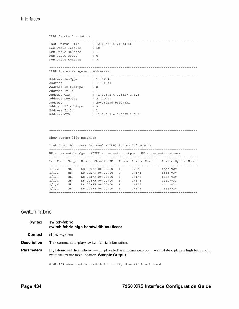
Interfaces
Page 434 7950 XRS Interface Configuration Guide
LLDP Remote Statistics-------------------------------------------------------------------------------Last Change Time : 12/08/2014 21:34:48Rem Table Inserts : 10Rem Table Deletes : 1Rem Table Drops : 0Rem Table Ageouts : 3
-------------------------------------------------------------------------------LLDP System Management Addresses-------------------------------------------------------------------------------Address SubType : 1 (IPv4)Address : 1.1.1.31Address If SubType : 2Address If Id : 1Address OID : .1.3.6.1.4.1.6527.1.3.3Address SubType : 2 (IPv6)Address : 2001:dead:beef::31Address If SubType : 2 Address If Id : 1Address OID : .1.3.6.1.4.1.6527.1.3.3
===============================================================================
show system lldp neighbor
Link Layer Discovery Protocol (LLDP) System Information===============================================================================NB = nearest-bridge NTPMR = nearest-non-tpmr NC = nearest-customer===============================================================================Lcl Port Scope Remote Chassis ID Index Remote Port Remote System Name-------------------------------------------------------------------------------1/1/2 NB D8:1D:FF:00:00:00 1 1/2/2 cses-v291/1/5 NB D8:1E:FF:00:00:00 2 1/1/4 cses-v301/1/7 NB D8:1E:FF:00:00:00 3 1/1/6 cses-v301/1/4 NB D8:20:FF:00:00:00 5 1/1/5 cses-v321/1/6 NB D8:20:FF:00:00:00 6 1/1/7 cses-v321/1/1 NB D8:1C:FF:00:00:00 9 1/2/2 cses-V28===============================================================================
switch-fabric
Syntax switch-fabricswitch-fabric high-bandwidth-multicast
Context show>system
Description This command displays switch fabric information.
Parameters high-bandwidth-multicast — Displays MDA information about switch-fabric plane’s high bandwidth multicast traffic tap allocation. Sample Output
A:SR-12# show system switch-fabric high-bandwidth-multicast

Interface Configuration
7950 XRS Interface Configuration Guide Page 435
===============================================================================Switch Fabric===============================================================================Slot/Mda Min Fwd Cap Max Fwd Cap Hi-Bw-Mcast Mcast Hi Mcast Low Group ------------------------------------------------------------------------------- 3/1 100% 100% Yes #15# #1# 1 4/1 100% 100% No 3 4 0 4/2 100% 100% No 1 2 0 8/1 100% 100% Yes #15# #1# 2 A 100% 100% No 0 0 0 B 100% 100% No 0 0 0 ===============================================================================

Interfaces
Page 436 7950 XRS Interface Configuration Guide
LAG Show Commands
lag
Syntax lag [lag-id] [detail] [statistics]lag [lag-id] descriptionlag [lag-id] portlag lag-id associationslag lag-id bfdlag lag-id [detail] eth-cfm [tunnel tunnel-id]lag lag-id associations per-link-hash interface [class {1 | 2 | 3}]lag lag-id associations link-map-profile [link-map-profile] interfacelag lag-id lacp-partnerlag lag-id detail lacp-partnerlag lag-id link-map-profile link-map-profilelag lag-id associations per-link-hash sap [class {1 | 2 | 3}]lag lag-id associations link-map-profile [link-map-profile] saplag lag-id per-link-hash [class {1 | 2 | 3}]lag lag-id per-link-hash port port-id
Context show
Description This command displays Link Aggregation Group (LAG) information.
If no command line options are specified, a summary listing of all LAGs is displayed.
Parameters lag-id — Displays only information on the specified LAG ID.
Default Display information for all LAG IDs.
Values 1 — 800
detail — Displays detailed LAG information.
Default Displays summary information.
statistics — Displays LAG statistics information.
associations — Displays a list of current router interfaces to which the LAG is assigned.
link-map-profile link-map-profile — Displays information about a particular LAG link map profile.
eth-cfm — Displays a list of Ethernet tunnels to which the LAG is assigned.
per-link-hash — Displays information about a SAP or interface associated with this LAG will send traffic over a single link of a LAG auto-rebalancing as links are added and removed from this LAG.
lacp-partner — Displays LACP partner information.
link-map-profile link-map-profile — Displays information about a specified LAG link map profile identifier.

Interface Configuration
7950 XRS Interface Configuration Guide Page 437
Output LAG Output — The following table describes LAG output fields.
Sample Output
A:ALA-48>config# show lag=============================================================================== Lag Data =============================================================================== Lag-id Adm Opr Port-Threshold Up-Link-Count MC Act/Stdby ------------------------------------------------------------------------------- 1 up down 0 0 N/A 2 up up 0 1 active 3 up down 0 0 standby 4 up down 0 0 standby 10 up down 0 0 N/A ------------------------------------------------------------------------------- Total Lag-ids: 5 Single Chassis: 2 MC Act: 1 MC Stdby: 2 =============================================================================== A:ALA-48>config# show lag
A:sr7- show lag 10 port===============================================================================Lag Port StatesLACP Status: e - Enabled, d - Disabled===============================================================================Lag-id Port-id Adm Act/Stdby Opr Primary Sub-group Forced Priority-------------------------------------------------------------------------------10(e) 1/1/8 up active up yes 1 - 32768 1/1/9 up standby down 2 - 32768===============================================================================
Detailed LAG Output — The following table describes detailed LAG output fields. The output is dependent on whether or not the LAG was configurd as a multi-chassis LAG.
Label Description
LAG ID The LAG or multi-link bundle ID that the port is assigned to.
Adm Up — The LAG is administratively up.
Down — The LAG is administratively down.
Opr Up — The LAG is operationally up.
Down — The LAG is operationally down.
Port-Threshold The number of operational links for the LAG at or below which the configured action will be invoked.
Up-Link-Count The number of ports that are physically present and have physical links present.
MC Act/Stdby Member port is selected as active or standby link.

Interfaces
Page 438 7950 XRS Interface Configuration Guide
Detailed LAG Output Fields
Label Description
LAG ID The LAG or multi-link trunk (MLT) that the port is assigned to.
Adm Up — The LAG is administratively up.Down — The LAG is administratively down.
Port Threshold If the number of available links is equal or below this number, the threshold action is executed.
Thres. Last Cleared
The last time that keepalive stats were cleared.
Dynamic Cost The OSPF costing of a link aggregation group based on the available aggregated, operational bandwidth.
Configured Address
The base chassis Ethernet MAC address.
Hardware Address The hardware address.
Hold-Time Down The timer, in tenths of seconds, which controls the delay between detecting that a LAG is down and reporting it to the higher levels.
LACP Enabled — LACP is enabled.Down — LACP is disabled.
LACP Transmit Intvl
LACP timeout signalled to peer.
Selection Crite-ria
Configured subgroup selection criteria.
MUX control Configured type of multiplexing machine control used in a LAG with LACP in active/passive modes.coupled — TX and RX activate together.independent — RX activates independent of TX.
Number of sub-groups
Total subgroups in LAG.
System ID System ID used by actor in LACP messages.
Admin Key Configured LAG key.
Oper Key Key used by actor in LACP messages.
System Priority System priority used by actor in LACP messages.
Prtr System ID System ID used by partner in LACP messages.
Prtr Oper Key Key used by partner in LACP messages.
Prtr System Pri-ority
System priority used by partner in LACP messages.

Interface Configuration
7950 XRS Interface Configuration Guide Page 439
Sample Output
A:sr7- show lag 10 detail ===============================================================================LAG Details===============================================================================Description : N/A-------------------------------------------------------------------------------Details-------------------------------------------------------------------------------Lag-id : 10 Mode : network
Mode LAG in access or network mode.
Opr Up — The LAG is operationally up.Down — The LAG is operationally down.
Port Threshold Configured port threshold.
Thres. Exceeded Cnt
The number of times that the drop count was reached.
Threshold Action Action to take when the number of available links is equal or below the port threshold.
Encap Type The encapsulation method used to distinguish customer traffic on a LAG.
Lag-IFIndex A box-wide unique number assigned to this interface.
Adapt QoS Displays the configured QoS mode.
Port ID The specific slot/MDA/port ID.
(LACP) Mode LACP active or passive mode.
LACP xmit standby
LACP transmits on standby links enabled / disabled.
Slave-to-partner Configured enabled/disabled.
Port-id Displays the member port ID.
Adm Displays the member port administrative state.
Active/stdby Indicates that the member port is selected as the active or standby link.
Opr Indicates that the member port operational state.
Primary Indicates that the member port is the primary port of the LAG.
Sub-group Displays the member subgroup where the member port belongs to.
Priority Displays the member port priority.
Label Description (Continued)

Interfaces
Page 440 7950 XRS Interface Configuration Guide
Adm : up Opr : upThres. Exceeded Cnt : 17 Port Threshold : 0Thres. Last Cleared : 01/22/2000 19:41:38 Threshold Action : downDynamic Cost : false Encap Type : nullConfigured Address : 0c:a4:02:20:69:4b Lag-IfIndex : 1342177290Hardware Address : 0c:a4:02:20:69:4bHold-time Down : 0.0 sec Port Type : standardPer FP Ing Queuing : disabled LACP : enabled Mode : activeLACP Transmit Intvl : fast LACP xmit stdby : enabledSelection Criteria : highest-count Slave-to-partner : disabledMUX control : coupledNumber of sub-groups: 2 Forced : -System Id : 0c:a4:02:20:68:01 System Priority : 32768Admin Key : 32770 Oper Key : 32770Prtr System Id : 0c:a4:02:1f:88:01 Prtr System Priority : 32768Prtr Oper Key : 32771 Standby Signaling : lacp
-------------------------------------------------------------------------------Port-id Adm Act/Stdby Opr Primary Sub-group Forced Prio -------------------------------------------------------------------------------1/1/8 up active up yes 1 - 327681/1/9 up standby down 2 - 32768
-------------------------------------------------------------------------------Port-id Role Exp Def Dist Col Syn Aggr Timeout Activity-------------------------------------------------------------------------------1/1/8 actor No No Yes Yes Yes Yes Yes Yes1/1/8 partner No No Yes Yes Yes Yes Yes Yes1/1/9 actor No No No No No Yes Yes Yes1/1/9 partner No No No No No Yes Yes Yes===============================================================================*A:sr7-
LAG Statistics Output — The following table describes detailed LAG statistics output fields.
LAG Statistics Output Fields
Label Description
LAG ID The LAG or multi-link trunk (MLT) that the port is assigned to.
Port ID The port ID configured or displayed in the slot/mda/port format.
Input Bytes The number of incoming bytes for the LAG on a per-port basis.
Input Packets The number of incoming packets for the LAG on a per-port basis.
Output Bytes The number of outbound bytes for the LAG on a per-port basis.
Output Packets The number of outbound packets for the LAG on a per-port basis.

Interface Configuration
7950 XRS Interface Configuration Guide Page 441
Sample Output
ALA-1# show lag statistics===============================================================================LAG Statistics===============================================================================Description: Lag-id Port-id Input Input Output Output Input Output Bytes Packets Bytes Packets Errors Errors-------------------------------------------------------------------------------1 1/1/3 0 1006 0 2494 0 0 1/1/4 0 435 0 401 0 0 1/1/5 0 9968 0 9833 0 0 -------------------------------------------------------------------------------Totals 0 11409 0 12728 0 0 ===============================================================================ALA-1#
LAG Associations Output — The following table describes LAG associations output fields.
Sample Output
A:ALA-1# show lag 5 associations==============================================================================Interface Table==============================================================================Router/ServiceId Name Encap Val------------------------------------------------------------------------------Router: Base LAG2West 0
Input/Output Errors
For packet-oriented interfaces, the number of inbound packets that contained errors preventing them from being deliverable to a higher-layer protocol. For character- oriented or fixed-length interfaces, the number of inbound transmission units that contained errors preventing them from being deliverable to a higher-layer protocol.For packet-oriented interfaces, the number of outbound packets that could not be transmitted because of errors. For character-oriented or fixed-length interfaces, the number of outbound transmission units that could not be transmitted because of errors.
Totals Displays the column totals for bytes, packets, and errors.
Label Description
Service ID The service associated with the LAG.
Name The name of the IP interface.
Encap Val The Dot1q or QinQ values of the port for the IP interface.
Label Description (Continued)
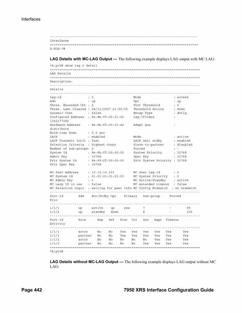
Interfaces
Page 442 7950 XRS Interface Configuration Guide
------------------------------------------------------------------------------Interfaces==============================================================================A:ALA-1#
LAG Details with MC-LAG Output — The following example displays LAG output with MC LAG:
*A:pc5# show lag 2 detail===============================================================================LAG Details===============================================================================Description:-------------------------------------------------------------------------------Details-------------------------------------------------------------------------------Lag-id : 2 Mode : accessAdm : up Opr : upThres. Exceeded Cnt : 2 Port Threshold : 0Thres. Last Cleared : 04/11/2007 21:50:55 Threshold Action : downDynamic Cost : false Encap Type : dot1qConfigured Address : 8e:8b:ff:00:01:42 Lag-IfIndex :1342177282Hardware Address : 8e:8b:ff:00:01:42 Adapt Qos :distributeHold-time Down : 0.0 secLACP : enabled Mode : activeLACP Transmit Intvl : fast LACP xmit stdby : enabledSelection Criteria : highest-count Slave-to-partner : disabledNumber of sub-groups: 2 Forced : -System Id : 8e:8b:ff:00:00:00 System Priority : 32768Admin Key : 32768 Oper Key : 32768Prtr System Id : 8e:89:ff:00:00:00 Prtr System Priority : 32768Prtr Oper Key : 32768
MC Peer Address : 10.10.10.101 MC Peer Lag-id : 2MC System Id : 01:01:01:01:01:01 MC System Priority : 2MC Admin Key : 1 MC Active/Standby : activeMC Lacp ID in use : false MC extended timeout : falseMC Selection Logic : waiting for peer info MC Config Mismatch : no mismatch-------------------------------------------------------------------------------Port-id Adm Act/Stdby Opr Primary Sub-group ForcedPrio-------------------------------------------------------------------------------1/1/1 up active up yes 7 - 991/1/2 up standby down 8 - 100-------------------------------------------------------------------------------Port-id Role Exp Def Dist Col Syn Aggr TimeoutActivity-------------------------------------------------------------------------------1/1/1 actor No No Yes Yes Yes Yes Yes Yes1/1/1 partner No No Yes Yes Yes Yes Yes Yes1/1/2 actor No No No No No Yes Yes Yes1/1/2 partner No No No No Yes Yes Yes Yes===============================================================================*A:pc5#
LAG Details without MC-LAG Output — The following example displays LAG output without MC LAG:
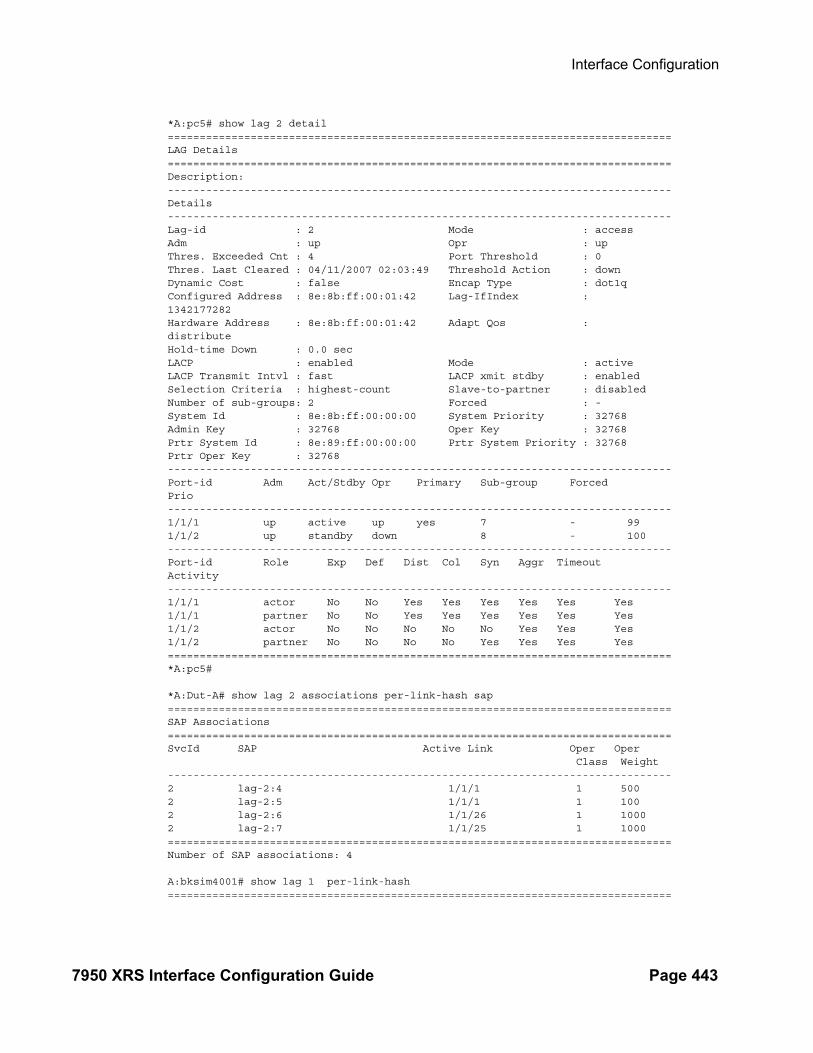
Interface Configuration
7950 XRS Interface Configuration Guide Page 443
*A:pc5# show lag 2 detail===============================================================================LAG Details===============================================================================Description:-------------------------------------------------------------------------------Details-------------------------------------------------------------------------------Lag-id : 2 Mode : accessAdm : up Opr : upThres. Exceeded Cnt : 4 Port Threshold : 0Thres. Last Cleared : 04/11/2007 02:03:49 Threshold Action : downDynamic Cost : false Encap Type : dot1qConfigured Address : 8e:8b:ff:00:01:42 Lag-IfIndex :1342177282Hardware Address : 8e:8b:ff:00:01:42 Adapt Qos :distributeHold-time Down : 0.0 secLACP : enabled Mode : activeLACP Transmit Intvl : fast LACP xmit stdby : enabledSelection Criteria : highest-count Slave-to-partner : disabledNumber of sub-groups: 2 Forced : -System Id : 8e:8b:ff:00:00:00 System Priority : 32768Admin Key : 32768 Oper Key : 32768Prtr System Id : 8e:89:ff:00:00:00 Prtr System Priority : 32768Prtr Oper Key : 32768-------------------------------------------------------------------------------Port-id Adm Act/Stdby Opr Primary Sub-group ForcedPrio-------------------------------------------------------------------------------1/1/1 up active up yes 7 - 991/1/2 up standby down 8 - 100-------------------------------------------------------------------------------Port-id Role Exp Def Dist Col Syn Aggr TimeoutActivity-------------------------------------------------------------------------------1/1/1 actor No No Yes Yes Yes Yes Yes Yes1/1/1 partner No No Yes Yes Yes Yes Yes Yes1/1/2 actor No No No No No Yes Yes Yes1/1/2 partner No No No No Yes Yes Yes Yes===============================================================================*A:pc5#
*A:Dut-A# show lag 2 associations per-link-hash sap===============================================================================SAP Associations===============================================================================SvcId SAP Active Link Oper Oper Class Weight-------------------------------------------------------------------------------2 lag-2:4 1/1/1 1 5002 lag-2:5 1/1/1 1 1002 lag-2:6 1/1/26 1 10002 lag-2:7 1/1/25 1 1000===============================================================================Number of SAP associations: 4
A:bksim4001# show lag 1 per-link-hash ===============================================================================

Interfaces
Page 444 7950 XRS Interface Configuration Guide
Per-link-hash Weight===============================================================================Port Class Num Users Agg Weight-------------------------------------------------------------------------------1/1/1 1 0 01/1/1 2 0 01/1/1 3 0 0===============================================================================Number of entries: 3===============================================================================

Interface Configuration
7950 XRS Interface Configuration Guide Page 445
LACP Partner Output — The following output shows LAG LACP partner information.
A:ALU-Dut1# show lag 3 lacp-partner===============================================================================LAG Partner information===============================================================================Partner system ID : ea:3e:ff:00:00:00Partner system priority : 32768Partner operational key : 2==============================================================================================================================================================LAG 3 Ports Partner operational information===============================================================================Port Actor Port Prio Key port-------------------------------------------------------------------------------1/1/52 33908 33909 5 21/1/54 33910 33911 5 21/1/56 33912 33913 7 2==============================================================================================================================================================LAG 3 Ports Partner operational state information===============================================================================Port Exp Def Dist Col Syn Aggr Time Act out-------------------------------------------------------------------------------1/1/52 No No Yes Yes Yes Yes Yes Yes1/1/54 No No Yes Yes Yes Yes Yes Yes1/1/56 No No No No No Yes Yes Yes===============================================================================A:ALU-Dut1#
A:Dut-A# show lag 10 lacp-neighbors ===============================================================================LAG Neighbor information===============================================================================Partner system ID : de:41:ff:00:00:00Partner system priority : 32768Partner operational key : 32768===============================================================================-------------------------------------------------------------------------------LAG port 1/1/6 partner information-------------------------------------------------------------------------------Actor port : 33862Partner admin system prio : 32768Partner oper system prio : 32768Partner admin system ID : 00:00:00:00:00:00Partner oper system ID : de:41:ff:00:00:00Partner admin key : 0Partner oper key : 32768Partner admin port : (Not Specified)Partner oper port : 33863Partner admin port prio : 32768Partner oper port prio : 32768Partner admin state : (Not Specified)Partner oper state : lacp-timeout aggregation synchronization collecting distributing

Interfaces
Page 446 7950 XRS Interface Configuration Guide
===============================================================================A:Dut-A#*A:bksim4001>config>lag# selection-criteria highest-weight subgroup-hold-time 1show lag 1 detail ght subgroup-hold-time 10 ===============================================================LAG Details===============================================================Description : To Sim4002-------------------------------------------------------------------------------Details-------------------------------------------------------------------------------Lag-id : 1 Mode : accessAdm : down Opr : downThres. Exceeded Cnt : 0 Port Threshold : 0Thres. Last Cleared : 01/21/2014 09:00:48 Threshold Action : downDynamic Cost : false Encap Type : nullConfigured Address : 36:95:ff:00:01:41 Lag-IfIndex : 1342177281Hardware Address : 36:95:ff:00:01:41 Adapt Qos (access) : distributeHold-time Down : 0.0 sec Port Type : standardPer-Link-Hash : disabled Include-Egr-Hash-Cfg: enabled Per FP Ing Queuing : disabled Per FP Egr Queuing : disabledPer FP SAP Instance : disabled LACP : enabled Mode : passiveLACP Transmit Intvl : fast LACP xmit stdby : enabledSelection Criteria : highest-weight Slave-to-partner : disabledSubgrp hold time : 20.0 sec Remaining time : 2.6 secSubgrp selected : 1 Subgrp candidate : 2Subgrp count : 2 Forced : -System Id : 36:95:ff:00:00:00 System Priority : 32768Admin Key : 32768 Oper Key : 32768Prtr System Id : Prtr System Priority : 0Prtr Oper Key : 0 Standby Signaling : lacp Port weight (gbps) : (Not Specified) Weight Threshold : 0 Threshold Action : down...===============================================================================
*A:Dut-A# show lag 2 associations per-link-hash sap===============================================================================SAP Associations===============================================================================SvcId SAP Active Link Oper Oper Class Weight-------------------------------------------------------------------------------2 lag-2:4 1/1/1 1 5002 lag-2:5 1/1/1 1 1002 lag-2:6 1/1/26 1 10002 lag-2:7 1/1/25 1 1000===============================================================================Number of SAP associations: 4
A:bksim4001# show lag 1 per-link-hash ===============================================================================Per-link-hash Weight===============================================================================

Interface Configuration
7950 XRS Interface Configuration Guide Page 447
Port Class Num Users Agg Weight-------------------------------------------------------------------------------1/1/1 1 10 101/1/1 2 0 01/1/1 3 2 500===============================================================================Number of entries: 3===============================================================================

Interfaces
Page 448 7950 XRS Interface Configuration Guide
Monitor Commands
card
Syntax card slot-number fp fp-number ingress {access|network} queue-group queue-group-name instance instance-id [absolute] [interval seconds] [repeat repeat] policer policer-id
Context monitor
Description This command monitors card parameters.
port
Syntax port port-id [port-id...(up to 5 max)] [interval seconds] [repeat repeat] [absolute | rate] [multiclass]
Context monitor
Description This command enables port traffic monitoring. The specified port(s) statistical information displays at the configured interval until the configured count is reached.
The first screen displays the current statistics related to the specified port(s). The subsequent statistical information listed for each interval is displayed as a delta to the previous display.
When the keyword rate is specified, the "rate per second" for each statistic is displayed instead of the delta.
Monitor commands are similar to show commands but only statistical information displays. Monitor commands display the selected statistics according to the configured number of times at the interval specified.
Parameters port port-id — Specify up to 5 port IDs.
Syntax: port-id slot/mda/port[.channel]interval seconds — Configures the interval for each display in seconds.
Default 10 seconds
Values 3 — 60
repeat repeat — Configures how many times the command is repeated.
Default 10
Values 1 — 999
absolute — When the absolute keyword is specified, the raw statistics are displayed, without processing. No calculations are performed on the delta or rate statistics.
rate — When the rate keyword is specified, the rate-per-second for each statistic is displayed instead of the delta.

Interface Configuration
7950 XRS Interface Configuration Guide Page 449
Sample Output
A:ALA-12>monitor# port 2/1/4 interval 3 repeat 3 absolute===============================================================================Monitor statistics for Port 2/1/4=============================================================================== Input Output-------------------------------------------------------------------------------At time t = 0 sec (Base Statistics)-------------------------------------------------------------------------------Octets 0 0Packets 39 175Errors 0 0-------------------------------------------------------------------------------At time t = 3 sec (Mode: Absolute)-------------------------------------------------------------------------------Octets 0 0Packets 39 175Errors 0 0-------------------------------------------------------------------------------At time t = 6 sec (Mode: Absolute)-------------------------------------------------------------------------------Octets 0 0Packets 39 175Errors 0 0-------------------------------------------------------------------------------At time t = 9 sec (Mode: Absolute)-------------------------------------------------------------------------------Octets 0 0Packets 39 175Errors 0 0===============================================================================A:ALA-12>monitor#
A:ALA-12>monitor# port 2/1/4 interval 3 repeat 3 rate===============================================================================Monitor statistics for Port 2/1/4=============================================================================== Input Output-------------------------------------------------------------------------------At time t = 0 sec (Base Statistics)-------------------------------------------------------------------------------Octets 0 0Packets 39 175Errors 0 0-------------------------------------------------------------------------------At time t = 3 sec (Mode: Rate)-------------------------------------------------------------------------------Octets 0 0Packets 0 0Errors 0 0-------------------------------------------------------------------------------At time t = 6 sec (Mode: Rate)-------------------------------------------------------------------------------Octets 0 0Packets 0 0Errors 0 0-------------------------------------------------------------------------------At time t = 9 sec (Mode: Rate)

Interfaces
Page 450 7950 XRS Interface Configuration Guide
-------------------------------------------------------------------------------Octets 0 0Packets 0 0Errors 0 0===============================================================================A:ALA-12>monitor#
===============================================================================*A:Cpm-A> monitor port bundle-fr-1/1.1===============================================================================Monitor statistics for Port bundle-fr-1/1.1=============================================================================== Input Output-------------------------------------------------------------------------------At time t = 0 sec (Base Statistics)--------------------------------------------------------------------------------Octets 0 0Packets 0 0Errors 0 0
queue-group
Syntax queue-group queue-group-name egress access egress-queue egress-queue-id [interval seconds] [repeat repeat] [absolute|rate]
Context monitor
Description This command enables queue-group monitoring for the specified parameters.
queue-group
Syntax queue-group queue-group-name ingress access ingress-queue ingress-queue-id [interval seconds] [repeat repeat] [absolute | rate]
Context monitor
Description This command enables queue-group monitoring for the specified parameters.
queue-group
Syntax queue-group queue-group-name egress network instance instance-id [policer policer-id] [egress-queue egress-queue-id] [interval seconds] [repeat repeat] [absolute | rate]
Context monitor
Description This command enables queue-group monitoring for the specified parameters.
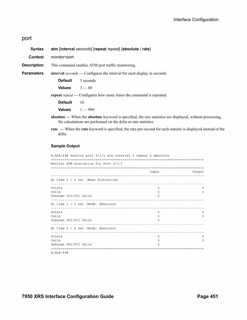
Interface Configuration
7950 XRS Interface Configuration Guide Page 451
port
Syntax atm [interval seconds] [repeat repeat] [absolute | rate]
Context monitor>port
Description This command enables ATM port traffic monitoring.
Parameters interval seconds — Configures the interval for each display in seconds.
Default 5 seconds
Values 3 — 60
repeat repeat — Configures how many times the command is repeated.
Default 10
Values 1 — 999
absolute — When the absolute keyword is specified, the raw statistics are displayed, without processing. No calculations are performed on the delta or rate statistics.
rate — When the rate keyword is specified, the rate-per-second for each statistic is displayed instead of the delta.
Sample Output
A:ALA-49# monitor port 9/1/1 atm interval 3 repeat 2 absolute===============================================================================Monitor ATM statistics for Port 9/1/1=============================================================================== Input Output-------------------------------------------------------------------------------At time t = 0 sec (Base Statistics)-------------------------------------------------------------------------------Octets 0 0Cells 0 0Unknown VPI/VCI Cells 0-------------------------------------------------------------------------------At time t = 3 sec (Mode: Absolute)-------------------------------------------------------------------------------Octets 0 0Cells 0 0Unknown VPI/VCI Cells 0-------------------------------------------------------------------------------At time t = 6 sec (Mode: Absolute)-------------------------------------------------------------------------------Octets 0 0Cells 0 0Unknown VPI/VCI Cells 0===============================================================================A:ALA-49#

Interfaces
Page 452 7950 XRS Interface Configuration Guide
Clear Commands
card
Syntax card slot-numbercard slot-number card slot-number fp [1..2] ingress mode {access|network} queue-group group-name instance instance statisticscard slot-number
Context clear
Description This command re-initializes the card in the specified slot.
Parameters slot-number — Clears information for the specified card slot.
Values 1 - 20: whether you are in xrs-20 or xrs-40 mode. C | D -> resets an extension CPM.
lag
Syntax lag lag-id statistics
Context clear
Description This command clears statistics for the specified LAG ID.
Parameters lag-id — The LAG ID to clear statistics.
Values 1 — 800
statistics — Specifies to clear statistics for the specified LAG ID.
mda
Syntax mda mda-id [statistics]
Context clear
Description This command reinitializes the specified MDA in a particular slot.
Parameters mda-id — Clears the specified slot and MDA.
statistics — Clears statistics for the specified MDA.

Interface Configuration
7950 XRS Interface Configuration Guide Page 453
port
Syntax port <port-id> phys-state-change-countport port-id ethernet efm-oam events local | remoteport port-id queue-group qgrp-id [instance instance-id] queue-depth [queue queue-id] {ingress|egress} [access|network]port port-id queue-group queue-group-name [access | network] {ingress | egress} [access|network] [{statistics|associations}]port port-id statistics
Context clear
Description This command clears port statistics for the specified port(s).
Parameters port-id — The port identifier.
port-id slot[/mda[/port]] or slot/mda/port[.channel]statistics — Specifies that port statistics will be cleared.
slot — The slot number.
Values 1 - 10
mda — The MDA number.
Default All MDAs.
Values 1, 2
7750 SR-c12: 1, 3, 5, 7, 9, 117750 SR-c12: 1-12pvc — Clears PVC statistics.
port-connection — Clears port-connection statistics.
phys-state-change-count — Clears the counter that tracks physical port state transitions for ethernet ports ("Phys State Chng Cnt" in "show port" output, or tmnxPortPhysStateChangeCount in the TIMETRA-PORT-MIB)
queue-group queue-group-name — Clears the specified port queue group name. It uniquely identifies a port ingress queue group in the managed system.
ingress — Clears ingress queue group information.
egress — Clears egress queue group information
ethernet — Specifies an Ethernet port will have the clear functions executed
efm-oam — Specifies the efm-oam will experience the cleared
events — specifies an efm-oam event will be cleared
local — only local efm-oam events will be cleared
remote — Only remote (received from peer) events will be cleared. Local and remote is not specified.
Default Without specifying an option, both local and remote are cleared.

Interfaces
Page 454 7950 XRS Interface Configuration Guide
queue-group
Syntax queue-group queue-group-name egress access egress-queue egress-queue-id [interval seconds] [repeat repeat] [absolute|rate]
Context clear
Description This command clears queue-group monitoring for the specified parameters.
queue-group
Syntax queue-group queue-group-name ingress access ingress-queue ingress-queue-id [interval seconds] [repeat repeat] [absolute | rate]
Context clear
Description This command clears queue-group monitoring for the specified parameters.
queue-group
Syntax queue-group queue-group-name egress network instance instance-id [policer policer-id] [egress-queue egress-queue-id] [interval seconds] [repeat repeat] [absolute | rate]
Context clear
Description This command clears queue-group monitoring for the specified parameters.

Interface Configuration
7950 XRS Interface Configuration Guide Page 455
Tools Commands
eth-tunnel
Syntax eth-tunnel tunnel-index [clear]
Context tools>dump
Description This command displays Ethernet tunnel information.
Sample Output
*A:PE-E# tools dump eth-tunnel 1
TunnelId 1 (Up/Up), Port eth-tunnel-1 (Up/Up): type g8031-1to1 NumMems 2/2, Up/Dn 0/0, active 0x1, present 0x3 baseMemPort 1/1/2 memId 1 (P), port 1/1/2 (Up), tag 1.0(Up) status (Up/Up) ccCnt-sf/ok 1/1 idx 0 tunId 1 memId 2 (S), port 2/1/2 (Up), tag 1.0(Up) status (Up/Up) ccCnt-sf/ok 0/0 idx 1 tunId 1
TunId = 1, state = Running, Active = Work, Now = 000 00:16:48.140 revert = 1, ReqState = NR-NULL, Pdu(Tx/Rx): 0x0f0000/0x0f0000 Defects = Running Timers = PduReTx Work MemId = 1 (1/1/2:1.0), state = Ok, cc = 000 00:16:23.510U ActiveCnt = 4, ActiveSeconds = 791 Protect MemId = 2 (2/1/2:1.0), state = Ok, cc = 000 00:09:47.560U ActiveCnt = 3, ActiveSeconds = 308 DbgCnts: swoEv = 2, wMemSts = 2, pMemSts = 0 rxPdu (valid/Invalid) = 4/0, wSfClr = 1, pSfClr = 0, wtrExp = 1 cm = 0, cmClr = 0, pm = 0, pmClr = 0, nr = 0, nrClr = 0 Seq Event TxPdu RxPdu Dir Act Time === ======== ============ ============ ===== ==== ================ 000 wMemSts 0xbf0101 wSF 0x0f0000 NR Tx--> Prot 000 00:16:12.450 001 RxPdu 0xbf0101 wSF 0x0f0101 NR Rx<-- Prot 000 00:16:12.450 002 RxPdu 0xbf0101 wSF 0xbf0101 wSF Rx<-- Prot 000 00:16:12.480 003 RxPdu 0xbf0101 wSF 0x0f0101 NR Rx<-- Prot 000 00:16:24.890 004 wSFClr 0x5f0101 WTR 0x0f0101 NR Tx--> Prot 000 00:16:25.030 005 WTR 0x0f0000 NR 0x0f0101 NR Tx--> Work 000 00:16:26.630 006 RxPdu 0x0f0000 NR 0x0f0000 NR Rx<-- Work 000 00:16:26.630*A:PE-E#
lag
Syntax lag lag-id lag-id
Context tools>dump
Description This command dumps LAG information.

Interfaces
Page 456 7950 XRS Interface Configuration Guide
Parameters lag-id — Specifies the LAG ID.
Values 1..800
map-to-phy-port
Syntax map-to-phy-port {ccag ccag-id | lag lag-id | eth-tunnel tunnel-index} {isid isid [end-isid isid] | service service-id | svc-name [end-service service-id | svc-name]} [summary]
Context tools>dump
Description This command provides the ability to respond to a query to provide the link in a LAG/Ethernet tunnel (loadsharing protection mode)/CCAG that is currently assigned to a given service-id or ISID.
Parameters lag-id — Specifies the LAG ID.
Values 1..800
isid — Specifies the ISID.
Values 0..16777215
service-id — Specifies the service ID.
Values 1..2147483648, 64 char max
tunnel-index — Specifies the tunnel index.
Values 1..1024
ccag-id — Specifies the CCAG ID.
Values 1..8
redundancy
Syntax redundancy
Context tools>dump
Description This command enables the context to dump redundancy parameters.
multi-chassis
Syntax multi-chassis
Context tools>dump>redundancy
Description This command enables the context to dump multi-chassis parameters.

Interface Configuration
7950 XRS Interface Configuration Guide Page 457
mc-ring
Syntax mc-ring
Context tools>dump>redundancy>multi-chassis
Description This command dumps multi-chassis ring data.
sync-database
Syntax sync-database [peer ip-address] [port port-id | lag-id] [sync-tag sync-tag] [application {dhcps | igmp | igmp-snooping | srrp | sub-mgmt | mld-snooping | mc-ring}] [detail] [type {alarm-deleted | local-deleted}]
Context tools>dump>redundancy>multi-chassis
Description This command dumps multi-chassis sync database information.
Parameters peer ip-address — Dumps the specified address of the multi-chassis peer.
port port-id — Dumps the specified port ID of the multi-chassis peer.
port lag-id — Dumps the specified Link Aggregation Group (LAG) on this system.
sync-tag sync-tag — Dumps the synchronization tag used while synchronizing this port with the multi-chassis peer.
application — Dumps the specified application information that was synchronized with the multi-chassis peer.
Values dhcps, igmp, igmp-snooping, mc-ring, srrp, sub-mgmt, mld-snooping, all
detail — Displays detailed information.
alarm-deleted|local-deleted — Filters by entry type.
Sample Output
A:Dut-C# tools dump redundancy multi-chassis sync-database application
<ip-address> : a.b.c.d <port-id|lag-id> : slot/mda/port or lag-<lag-id> <sync-tag> : [32 chars max] <application> : dhcp-server - local dhcp server igmp - internet group management protocol igmp-snooping - igmp-snooping mc-ring - multi-chassis ring mld - multicast listener discovery mld-snooping - multicast listener discovery-snooping srrp - simple router redundancy protocol sub-host-trk - subscriber host tracking sub-mgmt-ipoe - subscriber management for IPoE sub-mgmt-pppoe - subscriber management for PPPoE mc-ipsec - multi-chassis IPsec <detail> : keyword - displays detailed information

Interfaces
Page 458 7950 XRS Interface Configuration Guide
<type> : alarm-deleted|local-deleted|global-deleted| omcr-standby|omcr-alarmed
Values mda.bundle-num
bundle-num — Specifies the bundle number.
Values 1 — 256
lag
Syntax lag
Context tools>perform
Description This command provides tools for controlling LAG.
clear-force
Syntax clear-force all-mcclear-force lag-id lag-id [sub-group sub-group-id]clear-force peer-mc ip-address
Context tools>perform>lag
Description This command clears forced status.
Parameters all-mc —
lag-id lag-id — Specifies the LAG ID.
Values 1 — 800
sub-group sub-group-id — Specifies the subscriber group ID.
Values 1 — 16
peer-mc ip-address — Specfies the peer MC IP address.
force
Syntax force all-mc {active|standby}force lag-id lag-id [sub-group sub-group-id] {active|standby}force peer-mc peer-ip-address {active|standby}
Context tools>perform>lag
Description This commands allow forcing specified LAG, subgroup, all MC-LAGs or remote peer for MC-LAGs to become active or standby when LAG runs in Active/Standby mode. To remove forced condition, an operator must execute tools perform lag clear-force command.

Interface Configuration
7950 XRS Interface Configuration Guide Page 459
load-balance
Syntax load-balance lag-id lag-id [class {1|2|3}]
Context tools>perform>lag
Description Load balance specified LAG's links when per-link-hash weighted is deployed. Load balancing can be per specified class or on all classes if no class is specified.

Interfaces
Page 460 7950 XRS Interface Configuration Guide
Debug Commands
lag
Syntax lag [lag-id lag-id [port port-id]] [all]lag [lag-id lag-id [port port-id]] [sm] [pkt] [cfg] [red] [iom-upd] [port-state] [timers] [sel-logic] [mc] [mc-pkt]no lag [lag-id lag-id]
Context debug
Description This command enables debugging for LAG.
Parameters lag-id — Specifies the link aggregation group ID.
port-id — Specifies the physical port ID.
Syntax: slot/mda/port[.channel]
sm — Specifies to display trace LACP state machine.
pkt — Specifies to display trace LACP packets.
cfg — Specifies to display trace LAG configuration.
red — Specifies to display trace LAG high availability.
iom-upd — Specifies to display trace LAG IOM updates.
port-state — Specifies to display trace LAG port state transitions.
timers — Specifies to display trace LAG timers.
sel-logic — Specifies to display trace LACP selection logic.
mc — Specifies to display multi-chassis parameters.
mc-packet — Specifies to display the MC-LAG control packets with valid authentication were received on this system.

Standards and Protocol Support
ANCP/L2CP
RFC 5851, Framework and Requirements for an Access Node Control Mechanism in Broadband Multi-Service Networks
draft-ietf-ancp-protocol-02, Protocol for Access Node Control Mechanism in Broadband Networks
ATM
AF-ILMI-0065.000, Integrated Local Management Interface (ILMI) Version 4.0
AF-PHY-0086.001, Inverse Multiplexing for ATM (IMA) Specification Version 1.1
AF-TM-0121.000, Traffic Management Specification Version 4.1
AF-TM-0150.00, Addendum to Traffic Management v4.1 optional minimum desired cell rate indication for UBR
GR-1113-CORE, Asynchronous Transfer Mode (ATM) and ATM Adaptation Layer (AAL) Protocols Generic Requirements, Issue 1
GR-1248-CORE, Generic Requirements for Operations of ATM Network Elements (NEs), Issue 3
ITU-T I.432.1, B-ISDN user-network interface - Physical layer specification: General characteristics (02/99)
ITU-T I.610, B-ISDN operation and maintenance principles and functions (11/95)
RFC 1626, Default IP MTU for use over ATM AAL5
RFC 2684, Multiprotocol Encapsulation over ATM Adaptation Layer 5
BGP
RFC 1772, Application of the Border Gateway Protocol in the Internet
RFC 1997, BGP Communities Attribute
RFC 2385, Protection of BGP Sessions via the TCP MD5 Signature Option
RFC 2439, BGP Route Flap Damping
RFC 2545, Use of BGP-4 Multiprotocol Extensions for IPv6 Inter-Domain Routing
RFC 2858, Multiprotocol Extensions for BGP-4
RFC 2918, Route Refresh Capability for BGP-4
RFC 3107, Carrying Label Information in BGP-4
RFC 3392, Capabilities Advertisement with BGP-4
RFC 4271, A Border Gateway Protocol 4 (BGP-4)
RFC 4360, BGP Extended Communities Attribute
RFC 4364, BGP/MPLS IP Virtual Private Networks (VPNs)
RFC 4456, BGP Route Reflection: An Alternative to Full Mesh Internal BGP (IBGP)
RFC 4486, Subcodes for BGP Cease Notification Message
RFC 4659, BGP-MPLS IP Virtual Private Network (VPN) Extension for IPv6 VPN
Note: The information presented is subject to change without notice.
Alcatel-Lucent assumes no responsibility for inaccuracies contained herein.
7950 XRS Interface Configuration Guide Page 461

Standards and Protocol Support
RFC 4684, Constrained Route Distribution for Border Gateway Protocol/MultiProtocol Label Switching (BGP/MPLS) Internet Protocol (IP) Virtual Private Networks (VPNs)
RFC 4724, Graceful Restart Mechanism for BGP (Helper Mode)
RFC 4760, Multiprotocol Extensions for BGP-4
RFC 4798, Connecting IPv6 Islands over IPv4 MPLS Using IPv6 Provider Edge Routers (6PE)
RFC 4893, BGP Support for Four-octet AS Number Space
RFC 5004, Avoid BGP Best Path Transitions from One External to Another
RFC 5065, Autonomous System Confederations for BGP
RFC 5291, Outbound Route Filtering Capability for BGP-4
RFC 5575, Dissemination of Flow Specification Rules
RFC 5668, 4-Octet AS Specific BGP Extended Community
draft-ietf-idr-add-paths-04, Advertisement of Multiple Paths in BGP
draft-ietf-idr-best-external-03, Advertisement of the best external route in BGP
Circuit Emulation
MEF-8, Implementation Agreement for the Emulation of PDH Circuits over Metro Ethernet Networks, October 2004
RFC 4553, Structure-Agnostic Time Division Multiplexing (TDM) over Packet (SAToP)
RFC 5086, Structure-Aware Time Division Multiplexed (TDM) Circuit Emulation Service over Packet Switched Network (CESoPSN)
RFC 5287, Control Protocol Extensions for the Setup of Time-Division Multiplexing (TDM) Pseudowires in MPLS Networks
Ethernet
IEEE 802.1AB, Station and Media Access Control Connectivity Discovery
IEEE 802.1ad, Provider Bridges
IEEE 802.1ag, Connectivity Fault Management
IEEE 802.1ah, Provider Backbone Bridges
IEEE 802.1ak, Multiple Registration Protocol
IEEE 802.1aq, Shortest Path Bridging
IEEE 802.1ax, Link Aggregation
IEEE 802.1D, MAC Bridges
IEEE 802.1p, Traffic Class Expediting
IEEE 802.1Q, Virtual LANs
IEEE 802.1s, Multiple Spanning Trees
IEEE 802.1w, Rapid Reconfiguration of Spanning Tree
IEEE 802.1X, Port Based Network Access Control
IEEE 802.3ab, 1000BASE-T
IEEE 802.3ac, VLAN Tag
IEEE 802.3ad, Link Aggregation
IEEE 802.3ae, 10 Gb/s Ethernet
IEEE 802.3ah, Ethernet in the First Mile
IEEE 802.3ba, 40 Gb/s and 100 Gb/s Ethernet
IEEE 802.3i, Ethernet
IEEE 802.3u, Fast Ethernet
IEEE 802.3x, Ethernet Flow Control
IEEE 802.3z, Gigabit Ethernet
ITU-T G.8031, Ethernet Linear Protection Switching
ITU-T G.8032, Ethernet Ring Protection Switching
ITU-T Y.1731, OAM functions and mechanisms for Ethernet based networks
EVPN
RFC7432, BGP MPLS-Based Ethernet VPN
draft-ietf-bess-evpn-overlay-01, A Network Virtualization Overlay Solution using EVPN
draft-ietf-bess-evpn-prefix-advertisement-01, IP Prefix Advertisement in EVPN
Page 462 7950 XRS Interface Configuration Guide

Standards and Protocol Support
draft-ietf-bess-evpn-vpls-seamless-integ-00, (PBB-)EVPN Seamless Integration with (PBB-)VPLS
draft-ietf-l2vpn-pbb-evpn-10, Provider Backbone Bridging Combined with Ethernet VPN (PBB-EVPN)
draft-snr-bess-evpn-proxy-arp-nd-00, Proxy-ARP/ND function in EVPN networks
Fast Reroute
RFC 5286, Basic Specification for IP Fast Reroute: Loop-Free Alternates
RFC 7490, Remote Loop-Free Alternate (LFA) Fast Reroute (FRR)
draft-ietf-rtgwg-lfa-manageability-08, Operational management of Loop Free Alternates
draft-katran-mofrr-02, Multicast only Fast Re-Route
Frame Relay
ANSI T1.617 Annex D, DSS1 - Signalling Specification For Frame Relay Bearer Service
FRF.1.2, PVC User-to-Network Interface (UNI) Implementation Agreement
FRF.12, Frame Relay Fragmentation Implementation Agreement
FRF.16.1, Multilink Frame Relay UNI/NNI Implementation Agreement
FRF.5, Frame Relay/ATM PVC Network Interworking Implementation
FRF2.2, PVC Network-to-Network Interface (NNI) Implementation Agreement
ITU-T Q.933 Annex A, Additional procedures for Permanent Virtual Connection (PVC) status management
IP — General
RFC 768, User Datagram Protocol
RFC 793, Transmission Control Protocol
RFC 854, TELNET Protocol Specifications
RFC 951, Bootstrap Protocol (BOOTP)
RFC 1034, Domain Names - Concepts and Facilities
RFC 1035, Domain Names - Implementation and Specification
RFC 1350, The TFTP Protocol (revision 2)
RFC 1534, Interoperation between DHCP and BOOTP
RFC 1542, Clarifications and Extensions for the Bootstrap Protocol
RFC 2131, Dynamic Host Configuration Protocol
RFC 2347, TFTP Option Extension
RFC 2348, TFTP Blocksize Option
RFC 2349, TFTP Timeout Interval and Transfer Size Options
RFC 2428, FTP Extensions for IPv6 and NATs
RFC 2865, Remote Authentication Dial In User Service (RADIUS)
RFC 2866, RADIUS Accounting
RFC 2867, RADIUS Accounting Modifications for Tunnel Protocol Support
RFC 2868, RADIUS Attributes for Tunnel Protocol Support
RFC 3046, DHCP Relay Agent Information Option (Option 82)
RFC 3315, Dynamic Host Configuration Protocol for IPv6 (DHCPv6)
RFC 3596, DNS Extensions to Support IP version 6
RFC 3768, Virtual Router Redundancy Protocol (VRRP)
RFC 4250, The Secure Shell (SSH) Protocol Assigned Numbers
RFC 4251, The Secure Shell (SSH) Protocol Architecture
RFC 4254, The Secure Shell (SSH) Connection Protocol
RFC 5880, Bidirectional Forwarding Detection (BFD)
RFC 5881, Bidirectional Forwarding Detection (BFD) IPv4 and IPv6 (Single Hop)
RFC 5883, Bidirectional Forwarding Detection (BFD) for Multihop Paths
7950 XRS Interface Configuration Guide Page 463
Standards and Protocol Support
RFC 7130, Bidirectional Forwarding Detection (BFD) on Link Aggregation Group (LAG) Interfaces
draft-grant-tacacs-02, The TACACS+ Protocol
draft-ietf-vrrp-unified-spec-02, Virtual Router Redundancy Protocol Version 3 for IPv4 and IPv6
IP — Multicast
RFC 1112, Host Extensions for IP Multicasting
RFC 2236, Internet Group Management Protocol, Version 2
RFC 2375, IPv6 Multicast Address Assignments
RFC 2710, Multicast Listener Discovery (MLD) for IPv6
RFC 3306, Unicast-Prefix-based IPv6 Multicast Addresses
RFC 3376, Internet Group Management Protocol, Version 3
RFC 3446, Anycast Rendevous Point (RP) mechanism using Protocol Independent Multicast (PIM) and Multicast Source Discovery Protocol (MSDP)
RFC 3590, Source Address Selection for the Multicast Listener Discovery (MLD) Protocol
RFC 3618, Multicast Source Discovery Protocol (MSDP)
RFC 3810, Multicast Listener Discovery Version 2 (MLDv2) for IPv6
RFC 3956, Embedding the Rendezvous Point (RP) Address in an IPv6 Multicast Address
RFC 4601, Protocol Independent Multicast - Sparse Mode (PIM-SM): Protocol Specification (Revised)
RFC 4604, Using Internet Group Management Protocol Version 3 (IGMPv3) and Multicast Listener Discovery Protocol Version 2 (MLDv2) for Source-Specific Multicast
RFC 4607, Source-Specific Multicast for IP
RFC 4608, Source-Specific Protocol Independent Multicast in 232/8
RFC 4610, Anycast-RP Using Protocol Independent Multicast (PIM)
RFC 5059, Bootstrap Router (BSR) Mechanism for Protocol Independent Multicast (PIM)
RFC 5384, The Protocol Independent Multicast (PIM) Join Attribute Format
RFC 5496, The Reverse Path Forwarding (RPF) Vector TLV
RFC 6037, Cisco Systems' Solution for Multicast in MPLS/BGP IP VPNs
RFC 6513, Multicast in MPLS/BGP IP VPNs
RFC 6514, BGP Encodings and Procedures for Multicast in MPLS/IP VPNs
RFC 6515, IPv4 and IPv6 Infrastructure Addresses in BGP Updates for Multicast VPNs
RFC 6516, IPv6 Multicast VPN (MVPN) Support Using PIM Control Plane and Selective Provider Multicast Service Interface (S-PMSI) Join Messages
RFC 6625, Wildcards in Multicast VPN Auto-Discover Routes
RFC 6826, Multipoint LDP In-Band Signaling for Point-to-Multipoint and Multipoint-to-Multipoint Label Switched Path
RFC 7246, Multipoint Label Distribution Protocol In-Band Signaling in a Virtual Routing and Forwarding (VRF) Table Context
RFC 7385, IANA Registry for P-Multicast Service Interface (PMSI) Tunnel Type Code Points
draft-dolganow-l3vpn-mvpn-expl-track-00, Explicit tracking in MPLS/BGP IP VPNs
IP — Version 4
RFC 791, Internet Protocol
RFC 792, Internet Control Message Protocol
RFC 826, An Ethernet Address Resolution Protocol
RFC 1519, Classless Inter-Domain Routing (CIDR): an Address Assignment and Aggregation Strategy
RFC 1812, Requirements for IPv4 Routers
RFC 2401, Security Architecture for Internet Protocol
Page 464 7950 XRS Interface Configuration Guide

Standards and Protocol Support
RFC 3021, Using 31-Bit Prefixes on IPv4 Point-to-Point Links
IP — Version 6
RFC 1981, Path MTU Discovery for IP version 6
RFC 2460, Internet Protocol, Version 6 (IPv6) Specification
RFC 2464, Transmission of IPv6 Packets over Ethernet Networks
RFC 2529, Transmission of IPv6 over IPv4 Domains without Explicit Tunnels
RFC 3587, IPv6 Global Unicast Address Format
RFC 3633, IPv6 Prefix Options for Dynamic Host Configuration Protocol (DHCP) version 6
RFC 3646, DNS Configuration options for Dynamic Host Configuration Protocol for IPv6 (DHCPv6)
RFC 3736, Stateless Dynamic Host Configuration Protocol (DHCP) Service for IPv6
RFC 3971, SEcure Neighbor Discovery (SEND)
RFC 3972, Cryptographically Generated Addresses (CGA)
RFC 4007, IPv6 Scoped Address Architecture
RFC 4193, Unique Local IPv6 Unicast Addresses
RFC 4291, Internet Protocol Version 6 (IPv6) Addressing Architecture
RFC 4443, Internet Control Message Protocol (ICMPv6) for the Internet Protocol Version 6 (IPv6) Specification
RFC 4861, Neighbor Discovery for IP version 6 (IPv6)
RFC 4862, IPv6 Stateless Address Autoconfiguration (Router Only)
RFC 4941, Privacy Extensions for Stateless Address Autoconfiguration in IPv6
RFC 5007, DHCPv6 Leasequery
RFC 5095, Deprecation of Type 0 Routing Headers in IPv6
RFC 5952, A Recommendation for IPv6 Address Text Representation
RFC 6106, IPv6 Router Advertisement Options for DNS Configuration
RFC 6164, Using 127-Bit IPv6 Prefixes on Inter-Router Links
IPsec
RFC 2401, Security Architecture for the Internet Protocol
RFC 2406, IP Encapsulating Security Payload (ESP)
RFC 2409, The Internet Key Exchange (IKE)
RFC 2560, X.509 Internet Public Key Infrastructure Online Certificate Status Protocol - OCSP
RFC 3706, A Traffic-Based Method of Detecting Dead Internet Key Exchange (IKE) Peers
RFC 3947, Negotiation of NAT-Traversal in the IKE
RFC 3948, UDP Encapsulation of IPsec ESP Packets
RFC 4210, Internet X.509 Public Key Infrastructure Certificate Management Protocol (CMP)
RFC 4211, Internet X.509 Public Key Infrastructure Certificate Request Message Format (CRMF)
RFC 5996, Internet Key Exchange Protocol Version 2 (IKEv2)
RFC 5998, An Extension for EAP-Only Authentication in IKEv2
draft-ietf-ipsec-isakmp-mode-cfg-05, The ISAKMP Configuration Method
draft-ietf-ipsec-isakmp-xauth-06, Extended Authentication within ISAKMP/Oakley (XAUTH)
IS-IS
ISO/IEC 10589:2002, Second Edition, Nov. 2002, Intermediate system to Intermediate system intra-domain routeing information exchange protocol for use in conjunction with the protocol for providing the connectionless-mode Network Service (ISO 8473)
RFC 1195, Use of OSI IS-IS for Routing in TCP/IP and Dual Environments
7950 XRS Interface Configuration Guide Page 465

Standards and Protocol Support
RFC 2973, IS-IS Mesh Groups
RFC 3359, Reserved Type, Length and Value (TLV) Codepoints in Intermediate System to Intermediate System
RFC 3719, Recommendations for Interoperable Networks using Intermediate System to Intermediate System (IS-IS)
RFC 3787, Recommendations for Interoperable IP Networks using Intermediate System to Intermediate System (IS-IS)
RFC 4971, Intermediate System to Intermediate System (IS-IS) Extensions for Advertising Router Information
RFC 5120, M-ISIS: Multi Topology (MT) Routing in IS-IS
RFC 5130, A Policy Control Mechanism in IS-IS Using Administrative Tags
RFC 5301, Dynamic Hostname Exchange Mechanism for IS-IS
RFC 5302, Domain-wide Prefix Distribution with Two-Level IS-IS
RFC 5303, Three-Way Handshake for IS-IS Point-to-Point Adjacencies
RFC 5304, IS-IS Cryptographic Authentication
RFC 5305, IS-IS Extensions for Traffic Engineering TE
RFC 5306, Restart Signaling for IS-IS (Helper Mode)
RFC 5307, IS-IS Extensions in Support of Generalized Multi-Protocol Label Switching (GMPLS)
RFC 5308, Routing IPv6 with IS-IS
RFC 5309, Point-to-Point Operation over LAN in Link State Routing Protocols
RFC 5310, IS-IS Generic Cryptographic Authentication
RFC 6213, IS-IS BFD-Enabled TLV
RFC 6232, Purge Originator Identification TLV for IS-IS
RFC 6233, IS-IS Registry Extension for Purges
RFC 6329, IS-IS Extensions Supporting IEEE 802.1aq Shortest Path Bridging
draft-ietf-isis-mi-02, IS-IS Multi-Instance
draft-ietf-isis-segment-routing-extensions-04, IS-IS Extensions for Segment Routing
draft-kaplan-isis-ext-eth-02, Extended Ethernet Frame Size Support
Management
ianaaddressfamilynumbers-mib, IANA-ADDRESS-FAMILY-NUMBERS-MIB
ianagmplstc-mib, IANA-GMPLS-TC-MIB
ianaiftype-mib, IANAifType-MIB
ianaiprouteprotocol-mib, IANA-RTPROTO-MIB
IEEE8021-CFM-MIB, IEEE P802.1ag(TM) CFM MIB
IEEE8021-PAE-MIB, IEEE 802.1X MIB
IEEE8023-LAG-MIB, IEEE 802.3ad MIB
LLDP-MIB, IEEE P802.1AB(TM) LLDP MIB
SFLOW-MIB, sFlow MIB Version 1.3 (Draft 5)
RFC 1157, A Simple Network Management Protocol (SNMP)
RFC 1215, A Convention for Defining Traps for use with the SNMP
RFC 1724, RIP Version 2 MIB Extension
RFC 2021, Remote Network Monitoring Management Information Base Version 2 using SMIv2
RFC 2115, Management Information Base for Frame Relay DTEs Using SMIv2
RFC 2138, Remote Authentication Dial In User Service (RADIUS)
RFC 2206, RSVP Management Information Base using SMIv2
RFC 2213, Integrated Services Management Information Base using SMIv2
RFC 2494, Definitions of Managed Objects for the DS0 and DS0 Bundle Interface Type
RFC 2514, Definitions of Textual Conventions and OBJECT-IDENTITIES for ATM Management
RFC 2515, Definitions of Managed Objects for ATM Management
RFC 2571, An Architecture for Describing SNMP Management Frameworks
Page 466 7950 XRS Interface Configuration Guide

Standards and Protocol Support
RFC 2572, Message Processing and Dispatching for the Simple Network Management Protocol (SNMP)
RFC 2573, SNMP Applications
RFC 2574, User-based Security Model (USM) for version 3 of the Simple Network Management Protocol (SNMPv3)
RFC 2575, View-based Access Control Model (VACM) for the Simple Network Management Protocol (SNMP)
RFC 2578, Structure of Management Information Version 2 (SMIv2)
RFC 2579, Textual Conventions for SMIv2
RFC 2787, Definitions of Managed Objects for the Virtual Router Redundancy Protocol
RFC 2819, Remote Network Monitoring Management Information Base
RFC 2856, Textual Conventions for Additional High Capacity Data Types
RFC 2863, The Interfaces Group MIB
RFC 2864, The Inverted Stack Table Extension to the Interfaces Group MIB
RFC 2933, Internet Group Management Protocol MIB
RFC 3014, Notification Log MIB
RFC 3164, The BSD syslog Protocol
RFC 3165, Definitions of Managed Objects for the Delegation of Management Scripts
RFC 3231, Definitions of Managed Objects for Scheduling Management Operations
RFC 3273, Remote Network Monitoring Management Information Base for High Capacity Networks
RFC 3419, Textual Conventions for Transport Addresses
RFC 3498, Definitions of Managed Objects for Synchronous Optical Network (SONET) Linear Automatic Protection Switching (APS) Architectures
RFC 3584, Coexistence between Version 1, Version 2, and Version 3 of the Internet-standard Network Management Framework
RFC 3592, Definitions of Managed Objects for the Synchronous Optical Network/Synchronous Digital Hierarchy (SONET/SDH) Interface Type
RFC 3593, Textual Conventions for MIB Modules Using Performance History Based on 15 Minute Intervals
RFC 3635, Definitions of Managed Objects for the Ethernet-like Interface Types
RFC 3637, Definitions of Managed Objects for the Ethernet WAN Interface Sublayer
RFC 3826, The Advanced Encryption Standard (AES) Cipher Algorithm in the SNMP User-based Security Model
RFC 3877, Alarm Management Information Base (MIB)
RFC 3895, Definitions of Managed Objects for the DS1, E1, DS2, and E2 Interface Types
RFC 3896, Definitions of Managed Objects for the DS3/E3 Interface Type
RFC 4001, Textual Conventions for Internet Network Addresses
RFC 4022, Management Information Base for the Transmission Control Protocol (TCP)
RFC 4113, Management Information Base for the User Datagram Protocol (UDP)
RFC 4220, Traffic Engineering Link Management Information Base
RFC 4292, IP Forwarding Table MIB
RFC 4293, Management Information Base for the Internet Protocol (IP)
RFC 4631, Link Management Protocol (LMP) Management Information Base (MIB)
RFC 4878, Definitions and Managed Objects for Operations, Administration, and Maintenance (OAM) Functions on Ethernet-Like Interfaces
RFC 5101, Specification of the IP Flow Information Export (IPFIX) Protocol for the Exchange of IP Traffic Flow Information
RFC 6241, Network Configuration Protocol (NETCONF)
7950 XRS Interface Configuration Guide Page 467

Standards and Protocol Support
RFC 6242, Using the NETCONF Protocol over Secure Shell (SSH)
draft-ieft-snmpv3-update-mib-05, Management Information Base (MIB) for the Simple Network Management Protocol (SNMP)
draft-ietf-idr-bgp4-mib-05, Definitions of Managed Objects for the Fourth Version of Border Gateway Protocol (BGP-4)
draft-ietf-isis-wg-mib-06, Management Information Base for Intermediate System to Intermediate System (IS-IS)
draft-ietf-mboned-msdp-mib-01, Multicast Source Discovery protocol MIB
draft-ietf-mpls-ldp-mib-07, Definitions of Managed Objects for the Multiprotocol Label Switching, Label Distribution Protocol (LDP)
draft-ietf-mpls-lsr-mib-06, Multiprotocol Label Switching (MPLS) Label Switching Router (LSR) Management Information Base Using SMIv2
draft-ietf-mpls-te-mib-04, Multiprotocol Label Switching (MPLS) Traffic Engineering Management Information Base
draft-ietf-ospf-mib-update-08, OSPF Version 2 Management Information Base
MPLS — General
RFC 3031, Multiprotocol Label Switching Architecture
RFC 3032, MPLS Label Stack Encoding
RFC 3443, Time To Live (TTL) Processing in Multi-Protocol Label Switching (MPLS) Networks
RFC 4023, Encapsulating MPLS in IP or Generic Routing Encapsulation (GRE)
RFC 4182, Removing a Restriction on the use of MPLS Explicit NULL
RFC 5332, MPLS Multicast Encapsulations
MPLS — GMPLS
RFC 3471, Generalized Multi-Protocol Label Switching (GMPLS) Signaling Functional Description
RFC 3473, Generalized Multi-Protocol Label Switching (GMPLS) Signaling Resource ReserVation Protocol-Traffic Engineering (RSVP-TE) Extensions
RFC 4204, Link Management Protocol (LMP)
RFC 4208, Generalized Multiprotocol Label Switching (GMPLS) User-Network Interface (UNI): Resource ReserVation Protocol-Traffic Engineering (RSVP-TE) Support for the Overlay Model
RFC 4872, RSVP-TE Extensions in Support of End-to-End Generalized Multi-Protocol Label Switching (GMPLS) Recovery
draft-ietf-ccamp-rsvp-te-srlg-collect-04, RSVP-TE Extensions for Collecting SRLG Information
MPLS — LDP
RFC 3037, LDP Applicability
RFC 3478, Graceful Restart Mechanism for Label Distribution Protocol (Helper Mode)
RFC 5036, LDP Specification
RFC 5283, LDP Extension for Inter-Area Label Switched Paths (LSPs)
RFC 5443, LDP IGP Synchronization
RFC 5561, LDP Capabilities
RFC 6388, Label Distribution Protocol Extensions for Point-to-Multipoint and Multipoint-to-Multipoint Label Switched Paths
RFC 6826, Multipoint LDP in-band signaling for Point-to-Multipoint and Multipoint-to-Multipoint Label Switched Paths
draft-ietf-mpls-ldp-ip-pw-capability-09, Controlling State Advertisements Of Non-negotiated LDP Applications
draft-ietf-mpls-ldp-ipv6-15, Updates to LDP for IPv6
Page 468 7950 XRS Interface Configuration Guide

Standards and Protocol Support
draft-pdutta-mpls-ldp-adj-capability-00, LDP Adjacency Capabilities
draft-pdutta-mpls-ldp-v2-00, LDP Version 2
draft-pdutta-mpls-multi-ldp-instance-00, Multiple LDP Instances
draft-pdutta-mpls-tldp-hello-reduce-04, Targeted LDP Hello Reduction
MPLS — MPLS-TP
RFC 5586, MPLS Generic Associated Channel
RFC 5921, A Framework for MPLS in Transport Networks
RFC 5960, MPLS Transport Profile Data Plane Architecture
RFC 6370, MPLS Transport Profile (MPLS-TP) Identifiers
RFC 6378, MPLS Transport Profile (MPLS-TP) Linear Protection
RFC 6426, MPLS On-Demand Connectivity and Route Tracing
RFC 6428, Proactive Connectivity Verification, Continuity Check and Remote Defect indication for MPLS Transport Profile
RFC 6478, Pseudowire Status for Static Pseudowires
RFC 7213, MPLS Transport Profile (MPLS-TP) Next-Hop Ethernet Addressing
MPLS — OAM
RFC 4379, Detecting Multi-Protocol Label Switched (MPLS) Data Plane Failures
RFC 6424, Mechanism for Performing Label Switched Path Ping (LSP Ping) over MPLS Tunnels
RFC 6425, Detecting Data Plane Failures in Point-to-Multipoint Multiprotocol Label Switching (MPLS) - Extensions to LSP Ping
MPLS — RSVP-TE
RFC 2702, Requirements for Traffic Engineering over MPLS
RFC 2747, RSVP Cryptographic Authentication
RFC 2961, RSVP Refresh Overhead Reduction Extensions
RFC 3097, RSVP Cryptographic Authentication -- Updated Message Type Value
RFC 3209, RSVP-TE: Extensions to RSVP for LSP Tunnels
RFC 3473, Generalized Multi-Protocol Label Switching (GMPLS) Signaling Resource ReserVation Protocol-Traffic Engineering (RSVP-TE) Extensions (IF_ID RSVP_HOP Object With Unnumbered Interfaces and RSVP-TE Graceful Restart Helper Procedures)
RFC 3477, Signalling Unnumbered Links in Resource ReSerVation Protocol - Traffic Engineering (RSVP-TE)
RFC 3564, Requirements for Support of Differentiated Services-aware MPLS Traffic Engineering
RFC 3906, Calculating Interior Gateway Protocol (IGP) Routes Over Traffic Engineering Tunnels
RFC 4090, Fast Reroute Extensions to RSVP-TE for LSP Tunnels
RFC 4124, Protocol Extensions for Support of Diffserv-aware MPLS Traffic Engineering
RFC 4125, Maximum Allocation Bandwidth Constraints Model for Diffserv-aware MPLS Traffic Engineering
RFC 4127, Russian Dolls Bandwidth Constraints Model for Diffserv-aware MPLS Traffic Engineering
RFC 4561, Definition of a Record Route Object (RRO) Node-Id Sub-Object
RFC 4875, Extensions to Resource Reservation Protocol - Traffic Engineering (RSVP-TE) for Point-to-Multipoint TE Label Switched Paths (LSPs)
RFC 4950, ICMP Extensions for Multiprotocol Label Switching
RFC 5151, Inter-Domain MPLS and GMPLS Traffic Engineering -- Resource Reservation Protocol-Traffic Engineering (RSVP-TE) Extensions
RFC 5712, MPLS Traffic Engineering Soft Preemption
7950 XRS Interface Configuration Guide Page 469

Standards and Protocol Support
RFC 5817, Graceful Shutdown in MPLS and Generalized MPLS Traffic Engineering Networks
draft-newton-mpls-te-dynamic-overbooking-00, A Diffserv-TE Implementation Model to dynamically change booking factors during failure events
NAT
RFC 5382, NAT Behavioral Requirements for TCP
RFC 5508, NAT Behavioral Requirements for ICMP
RFC 6146, Stateful NAT64: Network Address and Protocol Translation from IPv6 Clients to IPv4 Servers
RFC 6333, Dual-Stack Lite Broadband Deployments Following IPv4 Exhaustion
RFC 6334, Dynamic Host Configuration Protocol for IPv6 (DHCPv6) Option for Dual-Stack Lite
RFC 6888, Common Requirements For Carrier-Grade NATs (CGNs)
OpenFlow
ONF OpenFlow Switch Specification Version 1.3.1 (OpenFlow-hybrid switches)
OSPF
RFC 1586, Guidelines for Running OSPF Over Frame Relay Networks
RFC 1765, OSPF Database Overflow
RFC 2328, OSPF Version 2
RFC 3101, The OSPF Not-So-Stubby Area (NSSA) Option
RFC 3509, Alternative Implementations of OSPF Area Border Routers
RFC 3623, Graceful OSPF Restart Graceful OSPF Restart (Helper Mode)
RFC 3630, Traffic Engineering (TE) Extensions to OSPF Version 2
RFC 4203, OSPF Extensions in Support of Generalized Multi-Protocol Label Switching (GMPLS)
RFC 4222, Prioritized Treatment of Specific OSPF Version 2 Packets and Congestion Avoidance
RFC 4552, Authentication/Confidentiality for OSPFv3
RFC 4576, Using a Link State Advertisement (LSA) Options Bit to Prevent Looping in BGP/MPLS IP Virtual Private Networks (VPNs)
RFC 4577, OSPF as the Provider/Customer Edge Protocol for BGP/MPLS IP Virtual Private Networks (VPNs)
RFC 4970, Extensions to OSPF for Advertising Optional Router Capabilities
RFC 5185, OSPF Multi-Area Adjacency
RFC 5187, OSPFv3 Graceful Restart (Helper Mode)
RFC 5243, OSPF Database Exchange Summary List Optimization
RFC 5250, The OSPF Opaque LSA Option
RFC 5309, Point-to-Point Operation over LAN in Link State Routing Protocols
RFC 5340, OSPF for IPv6
RFC 5709, OSPFv2 HMAC-SHA Cryptographic Authentication
RFC 5838, Support of Address Families in OSPFv3
RFC 6987, OSPF Stub Router Advertisement
draft-ietf-ospf-prefix-link-attr-06, OSPFv2 Prefix/Link Attribute Advertisement
draft-ietf-ospf-segment-routing-extensions-04, OSPF Extensions for Segment Routing
Policy Management and Credit Control
3GPP TS 29.212, Policy and Charging Control (PCC) over Gx/Sd Reference Point (Release 11 and Release 12) Gx support as it applies to wireline environment (BNG)
RFC 3588, Diameter Base Protocol
RFC 4006, Diameter Credit-Control Application
Page 470 7950 XRS Interface Configuration Guide

Standards and Protocol Support
PPP
RFC 1332, The PPP Internet Protocol Control Protocol (IPCP)
RFC 1377, The PPP OSI Network Layer Control Protocol (OSINLCP)
RFC 1661, The Point-to-Point Protocol (PPP)
RFC 1662, PPP in HDLC-like Framing
RFC 1877, PPP Internet Protocol Control Protocol Extensions for Name Server Addresses
RFC 1989, PPP Link Quality Monitoring
RFC 1990, The PPP Multilink Protocol (MP)
RFC 1994, PPP Challenge Handshake Authentication Protocol (CHAP)
RFC 2153, PPP Vendor Extensions
RFC 2516, A Method for Transmitting PPP Over Ethernet (PPPoE)
RFC 2615, PPP over SONET/SDH
RFC 2661, Layer Two Tunneling Protocol "L2TP"
RFC 2686, The Multi-Class Extension to Multi-Link PPP
RFC 2878, PPP Bridging Control Protocol (BCP)
RFC 4951, Fail Over Extensions for Layer 2 Tunneling Protocol (L2TP) "failover"
RFC 5072, IP Version 6 over PPP
Pseudowire
MFA Forum 9.0.0, The Use of Virtual trunks for ATM/MPLS Control Plane Interworking
MFA Forum 12.0.0, Multiservice Interworking - Ethernet over MPLS
MFA Forum 13.0.0, Fault Management for Multiservice Interworking v1.0
MFA Forum 16.0.0, Multiservice Interworking - IP over MPLS
RFC 3916, Requirements for Pseudo- Wire Emulation Edge-to-Edge (PWE3)
RFC 3985, Pseudo Wire Emulation Edge-to-Edge (PWE3)
RFC 4385, Pseudo Wire Emulation Edge-to-Edge (PWE3) Control Word for Use over an MPLS PSN
RFC 4446, IANA Allocations for Pseudowire Edge to Edge Emulation (PWE3)
RFC 4447, Pseudowire Setup and Maintenance Using the Label Distribution Protocol (LDP)
RFC 4448, Encapsulation Methods for Transport of Ethernet over MPLS Networks
RFC 4619, Encapsulation Methods for Transport of Frame Relay over Multiprotocol Label Switching (MPLS) Networks
RFC 4717, Encapsulation Methods for Transport Asynchronous Transfer Mode (ATM) over MPLS Networks
RFC 4816, Pseudowire Emulation Edge-to-Edge (PWE3) Asynchronous Transfer Mode (ATM) Transparent Cell Transport Service
RFC 5085, Pseudowire Virtual Circuit Connectivity Verification (VCCV): A Control Channel for Pseudowires
RFC 5659, An Architecture for Multi-Segment Pseudowire Emulation Edge-to-Edge
RFC 5885, Bidirectional Forwarding Detection (BFD) for the Pseudowire Virtual Circuit Connectivity Verification (VCCV)
RFC 6073, Segmented Pseudowire
RFC 6310, Pseudowire (PW) Operations, Administration, and Maintenance (OAM) Message Mapping
RFC 6391, Flow-Aware Transport of Pseudowires over an MPLS Packet Switched Network
RFC 6575, Address Resolution Protocol (ARP) Mediation for IP Interworking of Layer 2 VPNs
RFC 6718, Pseudowire Redundancy
RFC 6829, Label Switched Path (LSP) Ping for Pseudowire Forwarding Equivalence Classes (FECs) Advertised over IPv6
RFC 6870, Pseudowire Preferential Forwarding Status bit
7950 XRS Interface Configuration Guide Page 471

Standards and Protocol Support
RFC 7023, MPLS and Ethernet Operations, Administration, and Maintenance (OAM) Interworking
RFC 7267, Dynamic Placement of Multi-Segment Pseudowires
draft-ietf-l2vpn-vpws-iw-oam-04, OAM Procedures for VPWS Interworking
Quality of Service
RFC 2430, A Provider Architecture for Differentiated Services and Traffic Engineering (PASTE)
RFC 2474, Definition of the Differentiated Services Field (DS Field) in the IPv4 and IPv6 Headers
RFC 3260, New Terminology and Clarifications for Diffserv
RFC 2598, An Expedited Forwarding PHB
RFC 3140, Per Hop Behavior Identification Codes
RIP
RFC 1058, Routing Information Protocol
RFC 2080, RIPng for IPv6
RFC 2082, RIP-2 MD5 Authentication
RFC 2453, RIP Version 2
SONET/SDH
ITU-G.841, Types and Characteristics of SDH Networks Protection Architecture, issued in October 1998 and as augmented by Corrigendum 1, issued in July 2002
Timing
GR-1244-CORE, Clocks for the Synchronized Network: Common Generic Criteria, Issue 3, May 2005
GR-253-CORE, SONET Transport Systems: Common Generic Criteria. Issue 3, September 2000
ITU-T G.781, Synchronization layer functions, issued 09/2008
ITU-T G.813, Timing characteristics of SDH equipment slave clocks (SEC), issued 03/2003
ITU-T G.8261, Timing and synchronization aspects in packet networks, issued 04/2008
ITU-T G.8262, Timing characteristics of synchronous Ethernet equipment slave clock (EEC), issued 08/2007
ITU-T G.8264, Distribution of timing information through packet networks, issued 10/2008
ITU-T G.8265.1, Precision time protocol telecom profile for frequency synchronization, issued 10/2010
ITU-T G.8275.1, Precision time protocol telecom profile for phase/time synchronization with full timing support from the network, issued 07/2014
RFC 5905, Network Time Protocol Version 4: Protocol and Algorithms Specification
Voice and Video Performance
ETSI TS 101 329-5 Annex E, QoS Measurement for VoIP - Method for determining an Equipment Impairment Factor using Passive Monitoring
ITU-T G.1020 Appendix I, Performance Parameter Definitions for Quality of Speech and other Voiceband Applications Utilizing IP Networks - Mean Absolute Packet Delay Variation & Markov Models
ITU-T G.107, The E Model - A computational model for use in planning
ITU-T P.564, Conformance testing for voice over IP transmission quality assessment models
RFC 3550 Appendix A.8, RTP: A Transport Protocol for Real-Time Applications (Estimating the Interarrival Jitter)
VPLS
RFC 4761, Virtual Private LAN Service (VPLS) Using BGP for Auto-Discovery and Signaling
RFC 4762, Virtual Private LAN Service (VPLS) Using Label Distribution Protocol (LDP) Signaling
Page 472 7950 XRS Interface Configuration Guide

Standards and Protocol Support
RFC 5501, Requirements for Multicast Support in Virtual Private LAN Services
RFC 6074, Provisioning, Auto-Discovery, and Signaling in Layer 2 Virtual Private Networks (L2VPNs)
RFC 7041, Extensions to the Virtual Private LAN Service (VPLS) Provider Edge (PE) Model for Provider Backbone Bridging
RFC 7117, Multicast in Virtual Private LAN Service (VPLS)
7950 XRS Interface Configuration Guide Page 473

Standards and Protocol Support
Page 474 7950 XRS Interface Configuration Guide

Customer Documentation and ProductSupport
Customer Documentationhttp://documentation.alcatel-lucent.com
Technical Supporthttp://support.alcatel-lucent.com
Documentation [email protected]

© 2015 Alcatel-Lucent. All rights reserved.3HE 09862 AAAB TQZZA 01