Embed Size (px)
DESCRIPTION
Frank White Fluid Mechanics 7th Ed. Ch. 9 Solutions
Citation preview

Chapter 9 Compressible Flow
9.1 An ideal gas flows adiabatically through a duct. At section 1, p1 140 kPa, T1 260C, and V1 75 m/s. Farther downstream, p2 30 kPa and T2 207C. Calculate V2 in m/s and s2 s1 in J/(kgK) if the gas is (a) air, k 1.4, and (b) argon, k 1.67.
Fig. P9.1
Solution: (a) For air, take k 1.40, R 287 J/kgK, and cp 1005 J/kgK. The adiabatic steady-flow energy equation (9.23) is used to compute the downstream velocity:
or s2 s1 105 442 337 J/kgK Ans. (a)
(b) For argon, take k 1.67, R 208 J/kgK, and cp 518 J/kgK. Repeat part (a):
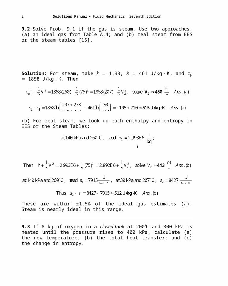
9.2 Solve Prob. 9.1 if the gas is steam. Use two approaches: (a) an ideal gas from Table A.4; and (b) real steam from EES or the steam tables [15].
Solutions Manual Fluid Mechanics, Seventh Edition
Solution: For steam, take k 1.33, R 461 J/kgK, and cp 1858 J/kgK. Then
(b) For real steam, we look up each enthalpy and entropy in EES or the Steam Tables:
These are within 1.5% of the ideal gas estimates (a). Steam is nearly ideal in this range.
9.3 If 8 kg of oxygen in a closed tank at 200C and 300 kPa is heated until the pressure rises to 400 kPa, calculate (a) the new temperature; (b) the total heat transfer; and (c) the change in entropy.
Solution: For oxygen, take k 1.40, R 260 J/kgK, and cv 650 J/kgK. Then
2
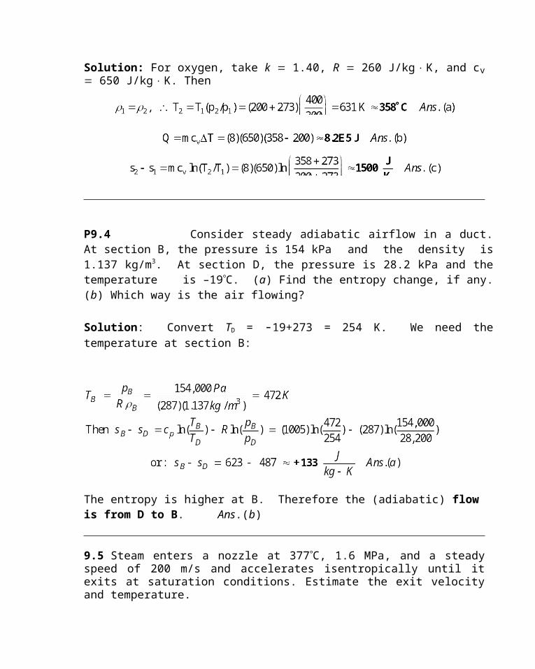
P9.4 Consider steady adiabatic airflow in a duct. At section B, the pressure is 154 kPa and the density is 1.137 kg/m3. At section D, the pressure is 28.2 kPa and the temperature is –19C. (a) Find the entropy change, if any. (b) Which way is the air flowing?
Solution: Convert TD = -19+273 = 254 K. We need the temperature at section B:
The entropy is higher at B. Therefore the (adiabatic) flow is from D to B. Ans.(b)
9.5 Steam enters a nozzle at 377C, 1.6 MPa, and a steady speed of 200 m/s and accelerates isentropically until it exits at saturation conditions. Estimate the exit velocity and temperature.
Solution: At saturation conditions, steam is not ideal. Use EES or the Steam Tables:
At 377C and 1.6 MPa, read h1 3.205E6 J/kg and s1 7153 J/kgK
At saturation for s1 s2 7153, read p2 185 kPa,
T2 118C, and h2 2.527E6 J/kg
This exit flow is supersonic, with a Mach number exceeding 2.0. We are assuming with this calculation that a (supersonic) shock wave does not form.
P9.6 Use EES, other software, or the Gas Tables, to estimate cp and cv, their ratio, and their difference, for carbon dioxide at 800K and 100 kPa. Compare with estimates similar to Eqs. (9.4).
Solutions Manual Fluid Mechanics, Seventh Edition
Solution: The writer used EES, for example, cp = CP(CarbonDioxide,T=800,P=100) and obtained the following results at 800K and 100 kPa:
cp = 1169 J/kg-K ; cv = 980 J/kg-K ; k = cp/cv = 1.19 ; cp – cv = 189 J/kg-K (=R)
The difference is still equal to the gas constant R, but the specific heats are about 50% higher
than would be estimated from Table A.4, which states (at room temperature), that k = 1.30 and R
= 189 J/kg-K:
So we give up a little accuracy by assuming constant specific heats if temperature changes are large.
P9.7 Air flows through a variable-area duct. At section 1, A1 = 20 cm2, p1 = 300 kPa, 1 = 1.75 kg/m3, and V1 = 122.5 m/s. At section 2, the area is exactly the same, but the density is much lower: 2 = 0.266 kg/m3, and T2 = 281 K. There is no transfer of work or heat. Assume one-dimensional steady flow. (a) How can you reconcile these differences? (b) Find the mass flow at section 2. Calculate (c) V2, (d) p2, and (e) s2 – s1. Hint: This problem requires the continuity equation.
Solution: Part (a) is too confusing, let’s try (b, c, d, e) first. (b) The mass flow must be constant:
That’s pretty fast! Check a2 = (kRT2)1/2 = [1.4(287)(281)]1/2 = 336 m/s. Hence the Mach number at section 2 is Ma2 = V2/a2 = 806/336 = 2.40. The flow at section 2 is supersonic! (d) The pressure at section 2 is easy, since the density and temperature are given:
4
(e) Finally, with pressures and temperatures known, the entropy change follows from Eq. (9.8):
Ahah! Now I get it. (a) The flow is isentropic. Ans.(a) The stagnation properties, To = 605 K, po = 319 kPa, and o = 1.805 kg/m3 are constant in the flow from section 1 to section 2.
9.8 Atmospheric air at 20C enters and fills an insulated tank which is initially evacuated. Using a control-volume analysis from Eq. (3.63), compute the tank air temperature when it is full.
Solution: The energy equation during filling of the adiabatic tank is
9.9 Liquid hydrogen and oxygen are burned in a combustion chamber and fed through a rocket nozzle which exhausts at 1600 m/s and exit pressure equal to ambient pressure of 54 kPa. The nozzle exit diameter is 45 cm, and the jet exit density is 0.15 kg/m3. If the exhaust gas has a molecular weight of 18, estimate (a) the exit gas temperature; (b) the mass flow; and (c) the thrust generated by the rocket.
Solution: (a) From Eq. (9.3), estimate Rgas and hence the gas exit temperature:

Solutions Manual Fluid Mechanics, Seventh Edition
(b) The mass flow follows from the exit velocity:
(c) The thrust was derived in Problem 3.68. When pexit pambient, we obtain
9.10 A certain aircraft flies at the same Mach number regardless of its altitude. Compared to its speed at 12000-m Standard Altitude, it flies 127 km/h faster at sea level. Determine its Mach number.
Solution: At sea level, T1 288.16 K. At 12000 m standard, T2 216.66 K. Then
9.11 At 300C and 1 atm, estimate the speed of sound of (a) nitrogen; (b) hydrogen; (c) helium; (d) steam; and (e) uranium hexafluoride 238UF6 (k 1.06).
Solution: The gas constants are listed in Appendix Table A.4 for all but uranium gas (e):
(a) nitrogen: k 1.40, R 297, T 300 273 573 K:
(b) hydrogen: k 1.41, R 4124,
(c) helium: k 1.66, R 2077:
(d) steam: k 1.33, R 461:
[NOTE: The EES “soundspeed” function would predict asteam = 586 m/s.]
(e) For uranium hexafluoride, we need only to compute R from the molecular weight:
6
9.12 Assume that water follows Eq. (1.19) with n 7 and B 3000. Compute the bulk modulus (in kPa) and the speed of sound (in m/s) at (a) 1 atm; and (b) 1100 atm (the deepest part of the ocean). (c) Compute the speed of sound at 20C and 9000 atm and compare with the measured value of 2650 m/s (A. H. Smith and A. W. Lawson, J. Chem. Phys., vol. 22, 1954, p. 351).
Solution: We may compute these values by differentiating Eq. (1.19) with k 1.0:
We may then substitute numbers for water, with pa 101350 Pa and a 998 kg/m3:
(a) at 1 atm: Kwater 7(3001)(101350)(1)7 2.129E9 Pa (21007 atm) Ans. (a)
P9.13 Consider steam at 500 K and 200 kPa. Estimate its speed of sound by three different methods: (a) using the handy new EES thermophysical function
SOUNDSPEED(Steam, p = p1,T = T1); (b) assuming an ideal gas from Table B.4; or
(c) using finite differences for isentropic densities between 210 kPa and 190 kPa.
Solutions Manual Fluid Mechanics, Seventh Edition
Solution: (a) Enter EES and use the new function, setting units to kPa and degrees Kelvin:
(b) Ideal gas approximation: From Table B.4 for H2O, k = 1.33 and R = 461 m2/s2-K:
This is 1.3% higher than EES, not bad. In this region, a better k would 1.30, not 1.33.
(c) Using finite differences of density and pressure at the same entropy as the given state:
Part (c) is the same as the EES result, so maybe that’s how the new function works?
P9.14 At 1 atm and 20C, the density of methyl alcohol is 49.4 lbm/ft3. At 300 atm, its density increases to 50.9 lbm/ft3. Use this data to estimate the speed of sound. Comment on the possible uncertainty of this estimate.
Solution: For convenience, convert the density data to SI units: 49.4 lbm/ft3 = 790.7 kg/m3, and 50.9 lbm/ft3 = 814.7 kg/m3. Then use finite differences to approximate the formula:
8
Since it relies on a small difference between two large densities, the density measurement must be very accurate. For example, a 1% error in density might cause a 50% error in speed of sound.
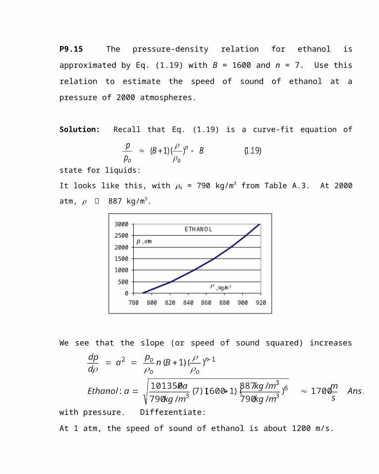
P9.15 The pressure-density relation for ethanol is approximated by Eq. (1.19) with
B = 1600 and n = 7. Use this relation to estimate the speed of sound of ethanol at a pressure
of 2000 atmospheres.
Solution: Recall that Eq. (1.19) is a curve-fit equation of state for liquids:
It looks like this, with o = 790 kg/m3 from Table A.3. At 2000 atm, 887 kg/m3.
We see that the slope (or speed of sound squared) increases with pressure. Differentiate:
At 1 atm, the speed of sound of ethanol is about 1200 m/s.
Solutions Manual Fluid Mechanics, Seventh Edition
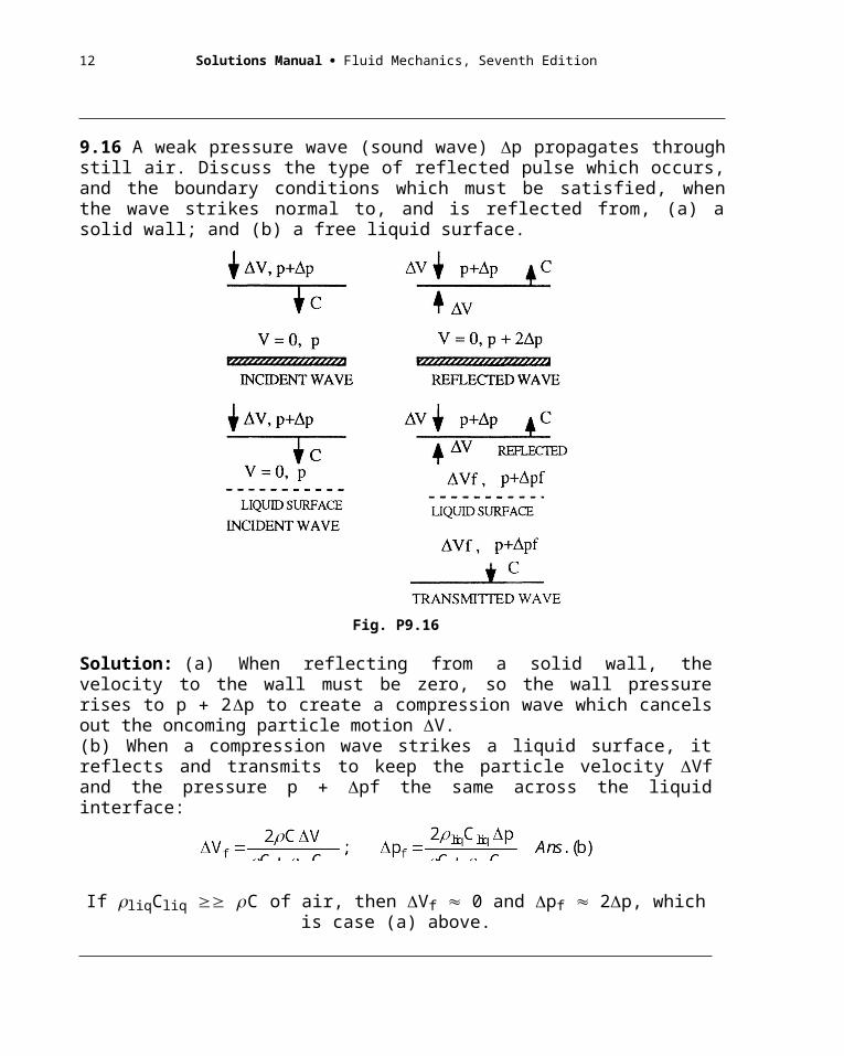
9.16 A weak pressure wave (sound wave) p propagates through still air. Discuss the type of reflected pulse which occurs, and the boundary conditions which must be satisfied, when the wave strikes normal to, and is reflected from, (a) a solid wall; and (b) a free liquid surface.
Fig. P9.16
Solution: (a) When reflecting from a solid wall, the velocity to the wall must be zero, so the wall pressure rises to p 2p to create a compression wave which cancels out the oncoming particle motion V.(b) When a compression wave strikes a liquid surface, it reflects and transmits to keep the particle velocity Vf and the pressure p pf the same across the liquid interface:
If liqCliq C of air, then Vf 0 and pf 2p, which is case (a) above.
9.17 A submarine at a depth of 800 m sends a sonar signal and receives the reflected wave back from a similar submerged object in 15 s. Using Prob. 9.12 as a guide, estimate the distance to the other object.
10
Solution: It probably makes little difference, but estimate a at a depth of 800 m:
at 800 m, p 101350 1025(9.81)(800) 8.15E6 Pa 80.4 atm
p/pa 80.4 3001( /1025)7 3000, solve 1029 kg/m3
Hardly worth the trouble: One-way distance a t/2 1457(15/2) 10900 m. Ans.
9.18 Race cars at the Indianapolis Speedway average speeds of 185 mi/h. After determining the altitude of Indianapolis, find the Mach number of these cars and estimate whether compressibility might affect their aerodynamics.
Solution: Rush to the Almanac and find that Indianapolis is at 220 m altitude, for which Table A.6 predicts that the standard speed of sound is 339.4 m/s 759 mi/h. Thus the Mach number is
Maracer V/a 185 mph/759 mph 0.24 Ans.
This is less than 0.3, so the Indianapolis Speedway need not worry about compressibility.
P9.19 In 1976, the SR-71A Blackbird, flying at 20 km standard altitude, set the jet-powered aircraft speed record of 3326 km/h. (a) Estimate the temperature, in C, at its front stagnation point. (b) At what Mach number would it have a front stagnation-point temperature of 500C?
Solution: At 20 km altitude, from Table A.6, T = 216.66K and a = 295.1 m/s. Convert the velocity from 3326 km/h to (3316)(1000)/(3600) = 924 m/s. Then Ma = V/a = 924/295.1 = 3.13. Compute
(b) To have a front stagnation temperature of 500C = 773 K, we could calculate
The SR-71A couldn’t fly that fast because of structural and heat transfer limitations.
Solutions Manual Fluid Mechanics, Seventh Edition
P9.20 Air flows isentropically in a channel. Properties at section 1 are V1 = 250 m/s, T1 = 330 K, and p1 = 80 kPa. At section 2 downstream, the temperature has dropped to 0C. Find (a) the pressure, (b) velocity, and (c) Mach number at section 2.
Solution: Assume k = 1.4 and, of course, convert T2 = 0C = 273 K. (b) The adiabatic energy equation will yield the new velocity:
(a) To calculate p2, we could go through the stagnation pressure (which is 110 kPa) or we could simply use the ideal gas temperature ratio, Eq. (9.9):
We have velocity and temperature at section 2, so we can easily calculate the Mach number:
9.21 CO2 expands isentropically through a duct from p1 125 kPa and T1 100C to p2 80 kPa and V2 325 m/s. Compute (a) T2; (b) Ma2; (c) To; (d) po; (e) V1; and (f) Ma1.
12
Solution: For CO2, from Table A.4, take k 1.30 and R 189 J/kgK. Compute the specific heat: cp kR/(k 1) 1.3(189)/(1.3 1) 819 J/kgK. The results follow in sequence:
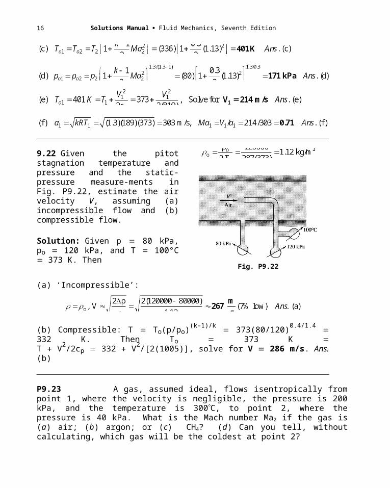
9.22 Given the pitot stagnation temperature and pressure and the static-pressure measure-ments in Fig. P9.22, estimate the air velocity V, assuming (a) incompressible flow and (b) compressible flow.
Solution: Given p 80 kPa, po 120 kPa, and T 100°C 373 K. Then
Fig. P9.22
(a) ‘Incompressible’:
(b) Compressible: T To(p/po)(k–1)/k 373(80/120)0.4/1.4 332 K. Then To 373 K T V2/2cp 332 V2/[2(1005)], solve for V 286 m/s. Ans. (b)
Solutions Manual Fluid Mechanics, Seventh Edition
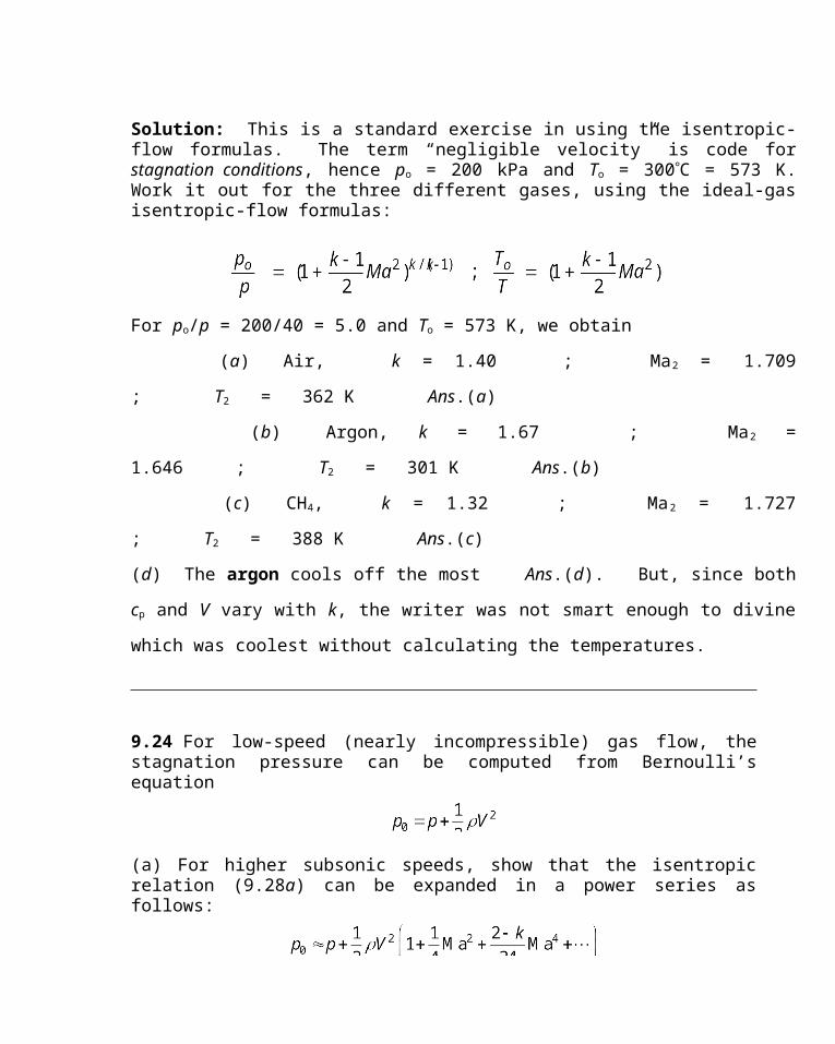
P9.23 A gas, assumed ideal, flows isentropically from point 1, where the velocity is negligible, the pressure is 200 kPa, and the temperature is 300C, to point 2, where the pressure is 40 kPa. What is the Mach number Ma2 if the gas is (a) air; (b) argon; or (c) CH4? (d) Can you tell, without calculating, which gas will be the coldest at point 2?
Solution: This is a standard exercise in using the isentropic-flow formulas. The term “negligible velocity” is code for stagnation conditions, hence po = 200 kPa and To = 300C = 573 K. Work it out for the three different gases, using the ideal-gas isentropic-flow formulas:
For po/p = 200/40 = 5.0 and To = 573 K, we obtain
(a) Air, k = 1.40 ; Ma2 = 1.709 ; T2 = 362 K Ans.(a)
(b) Argon, k = 1.67 ; Ma2 = 1.646 ; T2 = 301 K Ans.(b)
(c) CH4, k = 1.32 ; Ma2 = 1.727 ; T2 = 388 K Ans.(c)
(d) The argon cools off the most Ans.(d). But, since both cp and V vary with k, the writer
was not smart enough to divine which was coolest without calculating the temperatures.
9.24 For low-speed (nearly incompressible) gas flow, the stagnation pressure can be computed from Bernoulli’s equation
(a) For higher subsonic speeds, show that the isentropic relation (9.28a) can be expanded in a power series as follows:
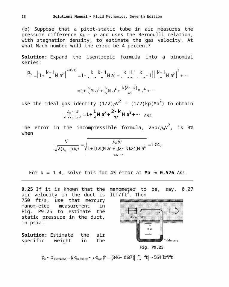
(b) Suppose that a pitot-static tube in air measures the pressure difference p0 – p and uses the Bernoulli relation, with stagnation density, to estimate the gas velocity. At what Mach number will the error be 4 percent?
Solution: Expand the isentropic formula into a binomial series:
14
Use the ideal gas identity (1/2)V2 (1/2)kp(Ma2) to obtain
Ans.
The error in the incompressible formula, 2p/oV2, is 4% when
For k 1.4, solve this for 4% error at Ma 0.576 Ans.
9.25 If it is known that the air velocity in the duct is 750 ft/s, use that mercury manom-eter measurement in Fig. P9.25 to estimate the static pressure in the duct, in psia.
Solution: Estimate the air specific weight in the manometer to be, say, 0.07 lbf/ft3. Then
Fig. P9.25
Then Ma V/a 750/1160 0.646
Solve for pstatic 1739 psf 12.1 lbf/in2 (abs) Ans.
9.26 Show that for isentropic flow of a perfect gas if a pitot-static probe measures p0, p, and T0, the gas velocity can be calculated from
Solutions Manual Fluid Mechanics, Seventh Edition
What would be a source of error if a shock wave were formed in front of the probe?
Solution: Assuming isentropic flow past the probe,
If there is a shock wave formed in front of the probe, this formula will yield the air velocity inside the shock wave, because the probe measures po2 inside the shock. The stagnation pressure in the outer stream is greater, as is the velocity outside the shock.
P9.27 A pitot tube, mounted on an airplane flying at 8000 m standard altitude, reads a stagnation pressure of 57 kPa. Estimate (a) the velocity in mi/h, and (b) the Mach number.
Solution: We assume that the static pressure is the standard atmosphere pressure at 8000 m, which from Table B.6 is 35,581 Pa. Then the isentropic pressure formula will yield the Mach number:
Gratifyingly, the speed of sound at 8000 m is given right in Table B.6: a = 308 m/s. Then
9.28 A large vacuum tank, held at 60 kPa absolute, sucks sea-level standard air through a converging nozzle of throat diameter 3 cm. Estimate (a) the mass flow rate; and (b) the Mach number at the throat.
Solution: For sea-level air take To 288 K, o 1.225 kg/m3, and po 101350 Pa. The pressure ratio is given, and we can assume isentropic flow with k 1.4:
16
We can then solve for exit temperature, density, and velocity, finally mass flow:
9.29 Steam from a large tank, where T 400C and p 1 MPa, expands isentropically through a small nozzle until, at a section of 2-cm diameter, the pressure is 500 kPa. Using the Steam Tables, estimate (a) the temperature; (b) the velocity; and (c) the mass flow at this section. Is the flow subsonic?
Solution: “Large tank” is code for stagnation values, thus To 400C and po 1 MPa. This problem involves dogwork in the tables and well illustrates why we use the ideal-gas law so readily. Using k 1.33 for steam, we find the flow is slightly supersonic:
That was quick. Instead, for more accuracy, use EES, assuming constant entropy:
At To 400C and po 1 MPa, read and
Then, at p 0.5 MPa, assuming s so, read T 302°C 575 K Ans. (a)
Also read h 3.067E6 J/kg and 1.908 kg/m3.
With h and ho known, the velocity follows from the adiabatic energy equation:
Solutions Manual Fluid Mechanics, Seventh Edition
The speed of sound is now included in EES, thanks, EES!
Finally, the mass flow is computed from the density and velocity:
We could have done nearly as well (2%) by simply assuming an ideal gas with k 1.33.
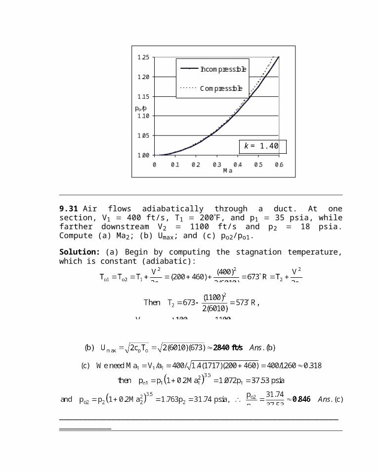
P9.30 When does the incompressible-flow assumption begin to fail for pressures? Construct a graph of po/p for incompressible flow of air as compared to Eq. (9.28a). Neglect gravity. Plot both versus Mach number for 0 £ Ma £ 0.6 and decide for yourself where the deviation is too great.
Solution: The Bernoulli incompressible equation can be converted to Mach number form:The two formulas are compared in the chart below. The difference becomes visible (but less
than 1%) at Ma = 0.3 (the usual criterion) but is still small (<2%) at Ma = 0.5.
18
9.31 Air flows adiabatically through a duct. At one section, V1 400 ft/s, T1 200F, and p1 35 psia, while farther downstream V2 1100 ft/s and p2 18 psia. Compute (a) Ma2; (b) Umax; and (c) po2/po1.
Solution: (a) Begin by computing the stagnation temperature, which is constant (adiabatic):
______________________________________________________________________
k = 1.40
Solutions Manual Fluid Mechanics, Seventh Edition
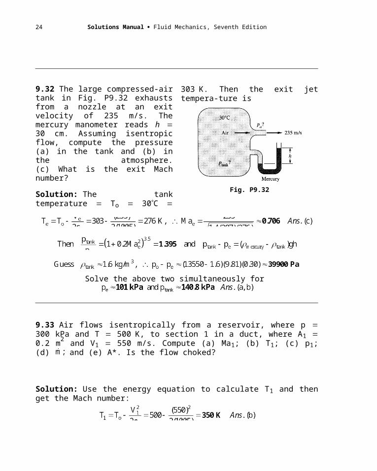
9.32 The large compressed-air tank in Fig. P9.32 exhausts from a nozzle at an exit velocity of 235 m/s. The mercury manometer reads h 30 cm. Assuming isentropic flow, compute the pressure (a) in the tank and (b) in the atmosphere.(c) What is the exit Mach number?
Solution: The tank temperature To 30C 303K. Then the exit jet tempera-ture is
Fig. P9.32
Solve the above two simultaneously for
9.33 Air flows isentropically from a reservoir, where p 300 kPa and T 500K, to section 1 in a duct, where A1 0.2 m2 and V1 550 m/s. Compute (a) Ma1; (b) T1; (c) p1; (d) and (e) A*. Is the flow choked?
Solution: Use the energy equation to calculate T1 and then get the Mach number:
The flow must be choked in order to produce supersonic flow in the duct. Answer.
20
P9.34 Carbon dioxide, in a large tank at 100C and 151 kPa, exhausts to a 1-atm
environment through a converging nozzle whose throat area is 5 cm2. Using isentropic
ideal-gas theory, calculate (a) the exit temperature, and (b) the mass flow.
Solution: For CO2, from Table A.4, take R = 189 m2/s2-K and k = 1.30. Find the exit Mach
number from the exit pressure ratio (guessing that the exit flow is subsonic, so pexit = patm):
To compute the mass flow, either find Ve and e or use the mass-flow function, Eq. (9.47).
With pressures known, an alternate method would use the mass-flow function, Eq. (9.47):
Solutions Manual Fluid Mechanics, Seventh Edition
The mass-flow function is a bit messy, but it gives the mass flow directly.
9.35 Helium, at To 400 K, enters a nozzle isentropically. At section 1, where A1 0.1 m2, a pitot-static arrangement (see Fig. P9.25) measures stagnation pressure of 150 kPa and static pressure of 123 kPa. Estimate (a) Ma1; (b) mass flow; (c) T1; and (d) A*.
Solution: For helium, from Table A.4, take k 1.66 and R 2077 J/kgK. (a) The local pressure ratio is given, hence we can estimate the Mach number:
Use this Mach number to estimate local temperature, density, velocity, and mass flow:
Finally, A* can be computed from Eq. (9.44), using k 1.66:
9.36 An air tank of volume 1.5 m3 is at 800 kPa and 20C when it begins exhausting through a converging nozzle to sea-level conditions. The throat area is 0.75 cm2. Estimate (a) the initial mass flow; (b) the time to blow down to 500 kPa; and (c) the time when the nozzle ceases being choked.
22
Solution: For sea level, pambient 101.35 kPa 0.528ptank, hence the flow is choked until the tank pressure drops to pambient/0.528 192 kPa. (a) We obtain
(b) For a control volume surrounding the tank, a mass balance gives
At 500 kPa, we obtain 500/800 exp(–0.00993t), or t 47 s Ans. (b)
At choking (192 kPa), 192/800 exp(–0.00993t), or t 144 s Ans. (c)
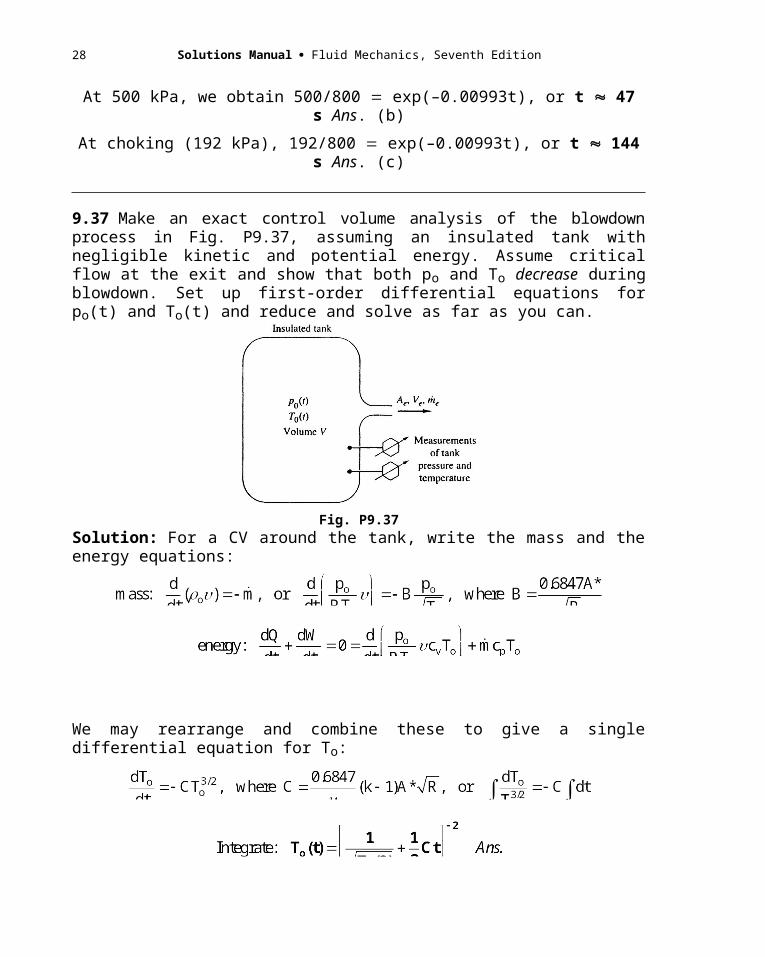
9.37 Make an exact control volume analysis of the blowdown process in Fig. P9.37, assuming an insulated tank with negligible kinetic and potential energy. Assume critical flow at the exit and show that both po and To decrease during blowdown. Set up first-order differential equations for po(t) and To(t) and reduce and solve as far as you can.
Fig. P9.37
Solution: For a CV around the tank, write the mass and the energy equations:
Solutions Manual Fluid Mechanics, Seventh Edition
We may rearrange and combine these to give a single differential equation for To:
With To(t) known, we could go back and solve the mass relation for po(t), but in fact that is not necessary. We simply use the isentropic-flow assumption:
Clearly, tank pressure also decreases with time as the tank blows down.
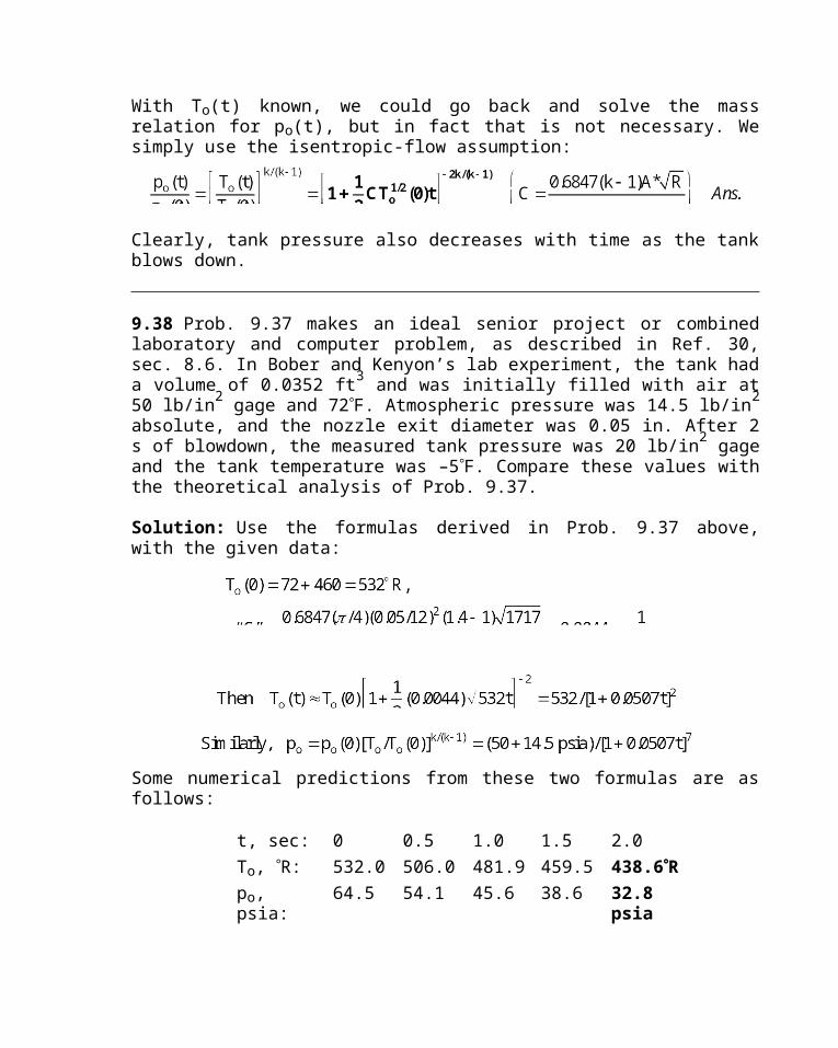
9.38 Prob. 9.37 makes an ideal senior project or combined laboratory and computer problem, as described in Ref. 30, sec. 8.6. In Bober and Kenyon’s lab experiment, the tank had a volume of 0.0352 ft3 and was initially filled with air at 50 lb/in2 gage and 72F. Atmospheric pressure was 14.5 lb/in2 absolute, and the nozzle exit diameter was 0.05 in. After 2 s of blowdown, the measured tank pressure was 20 lb/in2 gage and the tank temperature was –5F. Compare these values with the theoretical analysis of Prob. 9.37.
Solution: Use the formulas derived in Prob. 9.37 above, with the given data:
Some numerical predictions from these two formulas are as follows:
t, sec: 0 0.5 1.0 1.5 2.0
To, R: 532.0 506.0 481.9 459.5 438.6Rpo, psia: 64.5 54.1 45.6 38.6 32.8 psia
At t 2 sec, the tank temperature is 438.6R –21.4F, compared to –5F measured.
24
At t 2 sec, the tank pressure is 32.8 psia 18.3 psig, compared to 20 psig measured.The discrepancy is probably due to heat transfer through the tank walls warming the air.
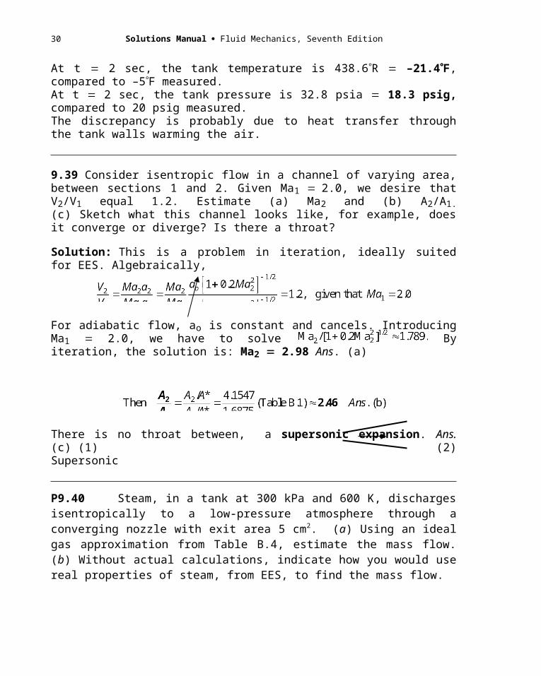
9.39 Consider isentropic flow in a channel of varying area, between sections 1 and 2. Given Ma1 2.0, we desire that V2/V1 equal 1.2. Estimate (a) Ma2 and (b) A2/A1.(c) Sketch what this channel looks like, for example, does it converge or diverge? Is there a throat?
Solution: This is a problem in iteration, ideally suited for EES. Algebraically,
For adiabatic flow, ao is constant and cancels. Introducing Ma1 2.0, we have to solve By iteration, the solution is: Ma2 2.98 Ans. (a)
There is no throat between, a supersonic expansion. Ans. (c) (1) (2) Supersonic
P9.40 Steam, in a tank at 300 kPa and 600 K, discharges isentropically to a low-pressure atmosphere through a converging nozzle with exit area 5 cm2. (a) Using an ideal gas approximation from Table B.4, estimate the mass flow. (b) Without actual calculations, indicate how you would use real properties of steam, from EES, to find the mass flow.
Solution: The code words “low-pressure atmosphere” mean that the flow is choked at the exit. For steam, from Table B.4, assume k = 1.33 and R = 461 m2/s2-K. Then we are at maximum mass flow:
Solutions Manual Fluid Mechanics, Seventh Edition
(b) Using EES for real steam, we don’t have these nice power-law formulas, but we can use the energy equation and the continuity equation and the fact that the entropy is constant:
First establish so from the given po and To. Then guess a velocity V, perhaps starting at 300 m/s, compute h from energy, then compute =(h, so) from the EES thermophysical functions. This enables us to calculate the (guessed) mass flow = A V. Is it a maximum? Probably not. Keep changing V until you reach a maximum mass flow. The final result obtained by the writer is
The perfect-gas result is very accurate. Steam is nearly ideal in this superheat region. Meanwhile, you could also use the new EES thermophysical function SOUNDSPEED for this problem, monitoring a for each guessed velocity V and computing the Mach number V/a. you would find that, at V = 559 m/s, the mass flow is maximum, and Ma = 1.000 (choked).
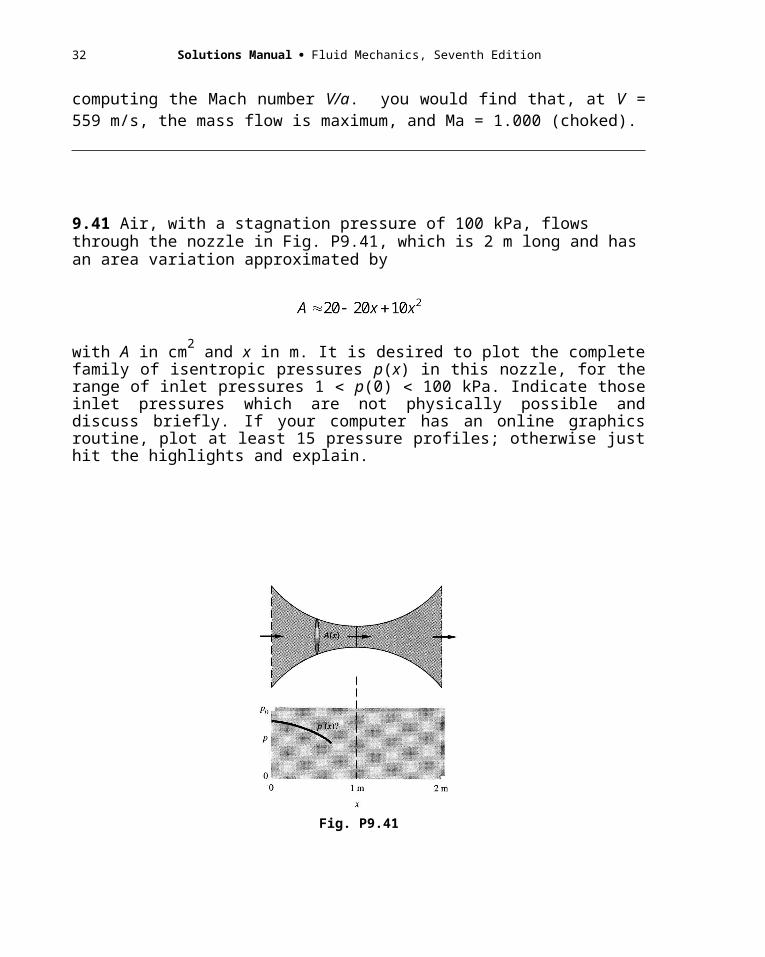
9.41 Air, with a stagnation pressure of 100 kPa, flows through the nozzle in Fig. P9.41, which is 2 m long and has an area variation approximated by
with A in cm2 and x in m. It is desired to plot the complete family of isentropic pressures p(x) in this nozzle, for the range of inlet pressures 1 p(0) 100 kPa. Indicate those inlet pressures which are not physically possible and discuss briefly. If your computer has an online graphics routine, plot at least 15 pressure profiles; otherwise just hit the highlights and explain.
26
Fig. P9.41
Solution: There is a subsonic entrance region of high pressure and a supersonic entrance region of low pressure, both of which are bounded by a sonic (critical) throat, and both of which have a ratio From Table B.1 or Eq. (9.44), we find these two conditions to be bounded by
a) subsonic entrance: A/A* 2.0, Mae 0.306, pe 0.9371po 93.71 kPa
b) supersonic entrance: A/A* 2.0, Mae 2.197, pe 0.09396po 9.396 kPa
Thus no isentropic flow can exist between entrance pressures 9.396 pe 93.71 kPa. The complete family of isentropic pressure curves is shown in the graph on the following page. They are not easy to find, because we have to convert implicitly from area ratio to Mach number.
9.42 A bicycle tire is filled with air at 169.12 kPa (abs) and 30C. The valve breaks, and air exhausts into the atmosphere of 100 kPa (abs) and 20C. The valve exit is 2-mm-diameter and is the smallest area in the system. Assuming one-dimensional isentropic flow, (a) find the initial Mach number, velocity, and temperature at the exit plane. (b) Find the initial mass flow rate. (c) Estimate the exit velocity using the incompressible Bernoulli equation. How well does this estimate agree with part (a)?
Solution: (a) Flow is not choked, because the pressure ratio is less than 1.89:
(b) Evaluate the exit density at Ma 0.90 and thence the mass flow:
Chapter 9 Compressible Flow 29
(c) Assume o tire, for how would we know exit if we didn’t use compressible-flow theory? Then the incompressible Bernoulli relation predicts
This is 8% lower than the “exact” estimate in part (a).
P9.43 Air flows isentropically through a variable-area duct. At section 1, A1 = 20 cm2, p1 = 300 kPa, 1 = 1.75 kg/m3, and Ma1 = 0.25. At section 2, the area is exactly the same, but the flow is much faster. Compute (a) V2; (b) Ma2; and (c) T2, and (d) the mass flow. (e) Is there a sonic throat between sections 1 and 2? If so, find its area.
Solution: If the areas are the same but the velocities different, there must be a sonic throat in be-tween. (e) We can find the throat area A* right away. For k = 1.40, from Eq. (9.45), Ma1 = 0.25,
(d) Compute V1 and then we can find the mass flow:
Now go over to section 2 and compute those properties. We have the same area ratio:
30 Solutions Manual Fluid Mechanics, Seventh Edition
9.44 In Prob. 3.34 we knew nothing about compressible flow at the time so merely assumed exit conditions p2 and T2 and computed V2 as an application of the continuity equation. Suppose that the throat diameter is 3 in. For the given stagnation conditions in the rocket chamber in Fig. P3.34 and assuming k 1.4 and a molecular weight of 26, computethe actual exit velocity, pressure, and temp-erature according to one-dimensional theory. If pa 14.7 lbf/in2 absolute, compute the thrust from the analysis of Prob. 3.68. This thrust is entirely independent of the stagna-tion temperature (check this by changing To to 2000°R if you like). Why?
Fig. P3.34
Solution: If M 26, then Rgas 49720/26 1912 ftlbf/slugR. Assuming choked flow in the throat (to produce a supersonic exit), the exit area ratio yields the exit Mach number:
Chapter 9 Compressible Flow 31
P9.45 Air flows isentropically from a large tank through a variable-area nozzle. At section 1, where A1 = 12 cm2, conditions are p1 = 20.5 kPa, T1 = 232 K, and V1 = 733 m/s. Find (a) the mass flow; (b) Ma1; (c) the throat area, if any; and (d) the pressure and temperature in the tank.
Solution: We have enough information at section 1 to find the mass flow:
And the information at section 1 also yields the local Mach number:
The local flow is supersonic, so there definitely is a sonic throat:
Finally, the tank (stagnation) conditions are calculated by the isentropic ratios:
P9.46 A one-dimensional isentropic airflow has the following properties at one section
where the area is 53 cm2: p = 12 kPa, = 0.182 kg/m3, and V = 760 m/s. Determine (a) the
throat area; (b) the stagnation temperature; and (c) the mass flow.
Solution: We already have what we need to compute the mass flow:
Now we need the Mach number at this section:
32 Solutions Manual Fluid Mechanics, Seventh Edition
The flow at this station is supersonic; therefore a sonic throat exists. We may now calculate
9.47 In wind-tunnel testing near Mach 1, a small area decrease caused by model blockage can be important. Let the test section area be 1 m2 and unblocked conditions are Ma 1.1 and T 20°C. What model area will first cause the test section to choke? If the model cross-section is 0.004 sq.m., what % change in test-section velocity results?
Solution: First evaluate the unblocked test conditions:
If A is blocked by 0.004 m2, then Anew 1.0 0.004 0.996 m2, and now
Thus a 0.4% decrease in test section area has caused a 2.1% decrease in test velocity.
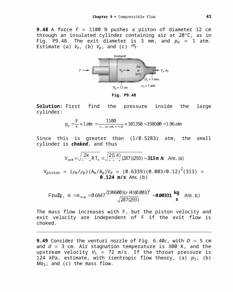
9.48 A force F 1100 N pushes a piston of diameter 12 cm through an insulated cylinder containing air at 20°C, as in Fig. P9.48. The exit diameter is 3 mm, and pa 1 atm. Estimate (a) Ve, (b) Vp, and (c)

Chapter 9 Compressible Flow 33
Fig. P9.48
Solution: First find the pressure inside the large cylinder:
Since this is greater than (1/0.5283) atm, the small cylinder is choked, and thus
Vpiston (e/p)(Ae/Ap)Ve (0.6339)(0.003/0.12)2(313) 0.124 m/s Ans. (b)
The mass flow increases with F, but the piston velocity and exit velocity are independent of F if the exit flow is choked.
9.49 Consider the venturi nozzle of Fig. 6.40c, with D 5 cm and d 3 cm. Air stagnation temperature is 300 K, and the upstream velocity V1 72 m/s. If the throat pressure is 124 kPa, estimate, with isentropic flow theory, (a) p1; (b) Ma2; and (c) the mass flow.
Solution: Given one-dimensional isentropic flow of air. The problem looks sticky— sparse, scattered information, implying laborious iteration. But the energy equation yields V1 and Ma1:
Area-ratio calculations will then yield A* and Ma2 and then po and p1:

34 Solutions Manual Fluid Mechanics, Seventh Edition
The mass flow follows from any of several formulas. For example:
P9.50 Carbon dioxide is stored in a tank at 100 kPa and 330 K. It discharges to a second tank through a converging nozzle whose exit area is 5 cm2. What is the initial mass flow rate if the second tank has a pressure of (a) 70 kPa, or (b) 40 kPa?
Solution: For CO2, from Table B.4, R = 189 m2/s2-K and k = 1.30. Calculate the pressure p* if the flow is choked at the exit:
Thus, for case (a), pb = 70, the nozzle is not choked. For case (b), pb = 40, it is choked. (a) We could plow through the various exit properties and finally find the mass flow:
Or we could do it all in one step with the handy mass flow function, Eq.(9.47), p/po = 0.546:
Chapter 9 Compressible Flow 35
(b) For an outside pressure of only 40 kPa < 54.6 kPa, the exit is choked:
P9.51 The scramjet engine of Fig. 9.30 is supersonic throughout. A sketch is shown in Fig. C9.8. Test the following design. The flow enters at Ma = 7 and air properties for 10,000 m altitude. Inlet area is 1 m2, the minimum area is 0.1 m2, and the exit area is
0.8 m2. If there is no combustion, (a) will the flow still be supersonic in the throat? Also, determine (b) the exit Mach number, (c) exit velocity, and (d) exit pressure.
Solution: From Table B.6 at 10,000 m, read p1 = 26416 Pa, T1 = 223.16 K, and 1 = 0.4125 kg/m3. Establish area ratio and stagnation conditions at the inlet, section 1:
Now, assuming isentropic flow (no combustion), work your way through the area ratios:
36 Solutions Manual Fluid Mechanics, Seventh Edition
9.52 A converging-diverging nozzle exits smoothly to sea-level standard atmosphere. It is supplied by a 40-m3 tank initially at 800 kPa and 100C. Assuming isentropic flow, estimate(a) the throat area; and (b) the tank pressure after 10 sec of operation. The exit area is 10 cm2.
Solution: The phrase “exits smoothly” means that exit pressure atmospheric pressure, which is 101 kPa. Then the pressure ratio specifies the exit Mach number:
The initial mass in the tank is quite large because of large volume and high pressure:
After 10 sec, blowing down at 0.99 kgs, we have about 299 10 289 kg left in the tank. The pressure will drop to about 800(289299) 773 kPa. Ans. (b).
9.53 Air flows steadily from a reservoir at 20C through a nozzle of exit area 20 cm2 and strikes a vertical plate as in Fig. P9.53. The flow is subsonic throughout. A force of 135 N is required to hold the plate stationary. Compute (a) Ve, (b) Mae, and (c) p0 if pa 101 kPa.
Fig. P9.53
Solution: Assume pe 1 atm. For a control volume surrounding the plate, we deduce that

Chapter 9 Compressible Flow 37
P9.54 The airflow in Prob. P9.46 undergoes a normal shock just past the section where
data was given. Determine the (a) Mach number, (b) pressure, and (c) velocity just
downstream of the shock. [Recall the given data: the area is 53 cm2, p = 12 kPa, = 0.182
kg/m3, and V = 760 m/s.]
Solution: In Prob. P9.46 we found that the local Mach number at the section was 2.5.
Table B.2: Ma2 = 0.513 Ans.(a) ;
p2/p1 = 7.125 , hence p2 = 7.125*12000 = 85500 Pa Ans.(b)
V1/V2 = 2/1 = 3.333 hence V2 = (760)/(3.333) = 228 m/s Ans.(c)
The shock results were quite easy – finding the upstream Mach number was the hard part.
9.55 Air, supplied by a reservoir at 450 kPa, flows through a converging-diverging nozzle whose throat area is 12 cm2. A normal shock stands where A1 20 cm2. (a) Compute the pressure just downstream of this shock. Still farther downstream, where A3 30 cm2, estimate (b) p3; (c) A3*; and (d) Ma3.
Solution: If a shock forms, the throat must be choked (sonic). Use the area ratio at (1):
38 Solutions Manual Fluid Mechanics, Seventh Edition
9.56 Air from a reservoir at 20C and 500 kPa flows through a duct and forms a normal shock downstream of a throat of area 10 cm2. By an odd coincidence it is found that the stagnation pressure downstream of this shock exactly equals the throat pressure. What is the area where the shock wave stands?
Solution: If a shock forms, the throat is sonic, A* 10 cm2. Now
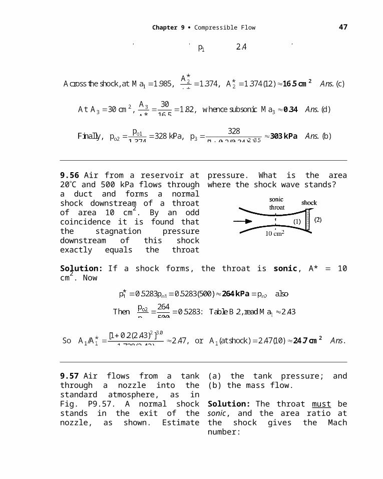
9.57 Air flows from a tank through a nozzle into the standard atmosphere, as in Fig. P9.57. A normal shock stands in the exit of the nozzle, as shown. Estimate (a) the tank pressure; and (b) the mass flow.
Solution: The throat must be sonic, and the area ratio at the shock gives the Mach number:
Fig. P9.57
Given that To 100C 373K and a critical throat area of 10 cm2, we obtain
Chapter 9 Compressible Flow 39
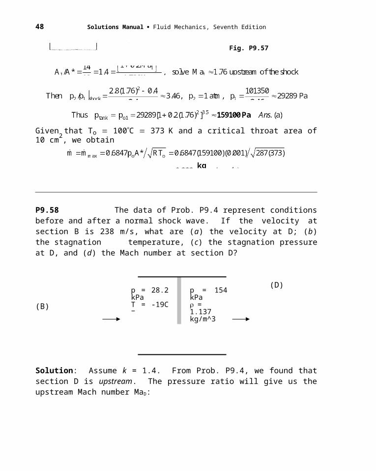
P9.58 The data of Prob. P9.4 represent conditions before and after a normal shock wave. If the velocity at section B is 238 m/s, what are (a) the velocity at D; (b) the stagnation temperature, (c) the stagnation pressure at D, and (d) the Mach number at section D?
(D) (B)
Solution: Assume k = 1.4. From Prob. P9.4, we found that section D is upstream. The pressure ratio will give us the upstream Mach number MaD:
With the upstream Mach number known, we can find the stagnation pressure there:
The downstream stagnation pressure (not asked) is much less, 189 kPa. Similarly, given TD = -19C = 254 K, we can calculate the stagnation temperature (good for both sides):
Finally, we could compute VD from the ratio across the shock, Eq. (9.58),
Alternately, VD = MaD (kRTD)1/2 = (2.20)[1.4(287)(254)]1/2 = (2.20)(319) = 702 m/s.
p = 28.2 kPaT = -19C = 254 K
p = 154 kPa= 1.137 kg/m^3V = 238m/s
40 Solutions Manual Fluid Mechanics, Seventh Edition
9.59 Air, at stagnation conditions of 450 K and 250 kPa, flows through a nozzle. At section 1, where the area 15 cm2, there is a normal shock wave. If the mass flow is 0.4 kgs, estimate (a) the Mach number; and (b) the stagnation pressure just downstream of the shock.
Solution: If there is a shock wave, then the mass flow is maximum:
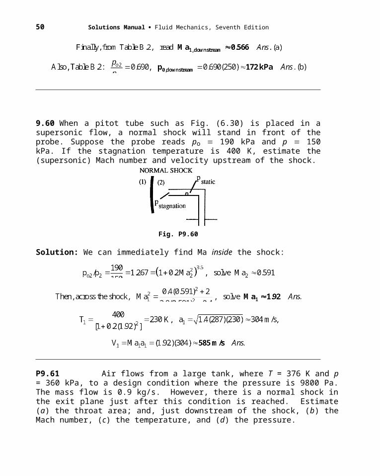
9.60 When a pitot tube such as Fig. (6.30) is placed in a supersonic flow, a normal shock will stand in front of the probe. Suppose the probe reads po 190 kPa and p 150 kPa. If the stagnation temperature is 400 K, estimate the (supersonic) Mach number and velocity upstream of the shock.
Fig. P9.60
Solution: We can immediately find Ma inside the shock:
Chapter 9 Compressible Flow 41
P9.61 Air flows from a large tank, where T = 376 K and p = 360 kPa, to a design condition where the pressure is 9800 Pa. The mass flow is 0.9 kg/s. However, there is a normal shock in the exit plane just after this condition is reached. Estimate (a) the throat area; and, just downstream of the shock, (b) the Mach number, (c) the temperature, and (d) the pressure.
Solution: The low design pressure definitely indicates a supersonic condition:
Find T1 in front of the shock and then use the normal shock conditions:
The problem worked out so that the external pressure was 1 atm.
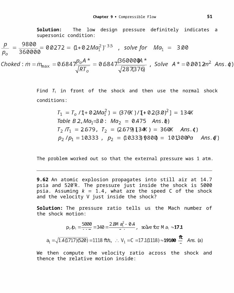
9.62 An atomic explosion propagates into still air at 14.7 psia and 520R. The pressure just inside the shock is 5000 psia. Assuming k 1.4, what are the speed C of the shock and the velocity V just inside the shock?
Solution: The pressure ratio tells us the Mach number of the shock motion:
We then compute the velocity ratio across the shock and thence the relative motion inside:
42 Solutions Manual Fluid Mechanics, Seventh Edition
Chapter 9 Compressible Flow 43
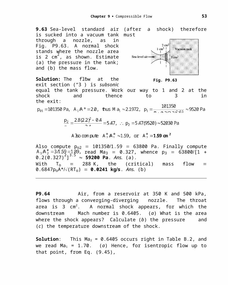
9.63 Sea-level standard air is sucked into a vacuum tank through a nozzle, as inFig. P9.63. A normal shock stands where the nozzle area is 2 cm2, as shown. Estimate (a) the pressure in the tank; and (b) the mass flow.
Solution: The flow at the exit section (“3”) is subsonic (after a shock) therefore must
Fig. P9.63
equal the tank pressure. Work our way to 1 and 2 at the shock and thence to 3 inthe exit:
Also compute po2 1013501.59 63800 Pa. Finally compute read Ma3 0.327, whence p3 63800[1 0.2(0.327)2]3.5 59200 Pa. Ans. (a).With To 288K, the (critical) mass flow 0.6847poA*(RTo) 0.0241 kgs. Ans. (b)
P9.64 Air, from a reservoir at 350 K and 500 kPa, flows through a converging-diverging nozzle. The throat area is 3 cm2. A normal shock appears, for which the downstream Mach number is 0.6405. (a) What is the area where the shock appears? Calculate (b) the pressure and (c) the temperature downstream of the shock.
Solution: This Ma2 = 0.6405 occurs right in Table B.2, and we read Ma1 = 1.70. (a) Hence, for isentropic flow up to that point, from Eq. (9.45),
(b) Calculate pressure before and after the shock:
44 Solutions Manual Fluid Mechanics, Seventh Edition
(c) Do the same thing as (b) to determine temperature downstream of the shock:
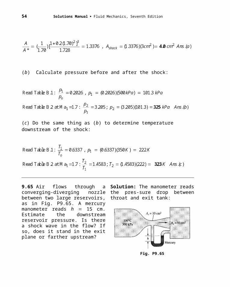
9.65 Air flows through a converging-diverging nozzle between two large reservoirs, as in Fig. P9.65. A mercury manometer reads h 15 cm. Estimate the downstream reservoir pressure. Is there a shock wave in the flow? If so, does it stand in the exit plane or farther upstream?
Solution: The manometer reads the pres-sure drop between throat and exit tank:
Fig. P9.65
But this pe is much lower than would occur in the duct for isentropic subsonic flow.
We can check also to see if isentropic supersonic flow is a possibility: With AeA* 3.0, the exit Mach number would be 2.64, corresponding to pe 0.047po 14 kPa (?). This is much too low, so that case fails also.
Suppose we had supersonic flow with a normal shock wave in the exit plane:

Chapter 9 Compressible Flow 45
This doesn’t match either, the flow expanded too much before the shock wave. Therefore the correct answer is: a normal shock wave upstream of the exit plane. Ans.
9.66 In Prob. 9.65 what would be the mercury manometer reading if the nozzle were operating exactly at supersonic “design” conditions?
Solution: We worked out this idealized isentropic-flow condition in Prob. 9.65:
Fig. P9.65
P9.67 A supply tank at 500 kPa and 400 K feeds air to a converging diverging nozzle whose throat area is 9 cm2. The exit area is 46 cm2. State the conditions in the nozzle if the pressure outside the exit plane is (a) 400 kPa; (b) 120 kPa; and (c) 9 kPa. (d) In each of these cases, find the mass flow.
Solution: For reference purposes, find the design (isentropic supersonic) condition for this nozzle:
This immediately establishes what happens in case (c):
poutside = 9000 Pa < pdesign, hence supersonic expansion outside the exit (Case I, Fig. 9.12)
Now determine the outside pressure if there is a normal shock in the exit plane:
This is close enough to case (b), a back pressure of 120 kPa, that we can say
there is a normal shock in the exit. (case F, Fig. 9.12) Ans.(b)
Finally, check the situation if the nozzle downstream of the throat is subsonic-isentropic:
46 Solutions Manual Fluid Mechanics, Seventh Edition
This is greater than case (a), a postulated back pressure of 450,000 Pa.
Thus case (a) will result in a normal shock just downstream of the throat. (Case D, Fig. 9.12)
In all three cases, the throat is choked, hence the mass flow is maximum:
9.68 Air in a tank at 120 kPa and 300 K exhausts to the atmosphere through a 5-cm2-throat converging nozzle at a rate of 0.12 kgs. What is the atmospheric pressure? What is the maximum mass flow possible at low atmospheric pressure?
Solution: Let us answer the second question first, to see where 0.12 kgs stands:
So the given mass flow is about 86% of maximum and patm 63 kPa. We could just go at it, guess the exit pressure and iterating, or we could express it more elegantly:
9.69 With reference to Prob. 3.68, show that the thrust of a rocket engine exhausting into a vacuum is given by
where Ae exit areaMae exit Mach number
p0 stagnation pressure in combustion chamber
Note that stagnation temperature does not enter into the thrust.
Chapter 9 Compressible Flow 47
Solution: In a vacuum, patm 0, the solution to Prob. 3.68 is
P9.70 Air, with po = 500 kPa and To = 600 K, flows through a converging-diverging nozzle. The exit area is 51.2 cm2, and the mass flow is 0.825 kg/s. What is the highest possible back pressure that will still maintain supersonic flow inside the diverging section?
Solution: Naturally assume isentropic flow with k = 1.40. If the flow is to be supersonic, there must be a choked throat. Find its area:
With A* known, we find the desired supersonic Mach number in the exit plane:
If 10,100 Pa were the back pressure, that would be the design condition. The highest possible back pressure would cause a normal shock in the exit plane and still allow supersonic flow inside:
48 Solutions Manual Fluid Mechanics, Seventh Edition
P9.71 A converging-diverging nozzle has a throat area of 10 cm2 and an exit area of 20 cm2. It is supplied by an air tank at 250 kPa and 350 K. (a) What is the design pressure at the exit? At one operating condition, the exit properties are pe = 183 kPa, Te = 340 K, and Ve = 144 m/s. (b) Can this condition be explained by a normal shock inside the nozzle? (c) If so, at what Mach number does the normal shock occur? [Hint: Use the change in A* to locate, if necessary, this position.]
Solution: First find the design conditions and also the actual Mach number at the exit:
So the actual exit flow is nowhere near design conditions. If we were so careful as to check for a normal shock in the exit plane, we would find an exit pressure of 128 kPa, much less than the given value of 183 kPa. Then yes, there is a normal shock inside the nozzle. Ans.(b)(c) To find where the shock is located, calculate the stagnation pressure and/or the area A* 2
for the given exit conditions.
Either one of these will tell us the Mach number where the normal shock occurred:
9.72 A large tank at 500 K and 165 kPa feeds air to a converging nozzle. The back pressure outside the nozzle exit is sea-level standard. What is the appropriate exit diameter if the desired mass flow is 72 kg/h?
Solution: Given To 500 K and po 165 kPa. The pressure ratio across the nozzle is (101.35 kPa)/(165 kPa) 0.614 0.528. Therefore the flow is not choked but instead exits at a high subsonic Mach number, with pthroat patm 101.35 kPa. Equation (9.47) is handy:

Chapter 9 Compressible Flow 49
The exit Mach number is approximately 0.86.
9.73 Air flows isentropically in a converging-diverging nozzle with a throat area of 3 cm2. At section 1, the pressure is 101 kPa, T1 300 K, and V1 868 ms. (a) Is the nozzle choked? Determine (b) A1; and (c) the mass flow. Suppose, without changing stagnation conditions of A1, the flexible throat is reduced to 2 cm2. Assuming shock-free flow, will there be any changes in the gas properties at section 1? If so, calculate the new p1, V1, and T1 and explain.
Solution: Check the Mach number. If choked, calculate the mass flow:
If po and To are unchanged and the throat (A*) is reduced from 3.0 to 2.0 cm2, the mass flow is cut by one-third and, if A1 remains the same (7.91 cm2), the area ratio changes and the Mach number will change at section 1:
Since the Mach number changes, all properties at section 1 change:
50 Solutions Manual Fluid Mechanics, Seventh Edition
A practical question might be: Does the new, reduced throat shape avoid flow separation and shock waves?
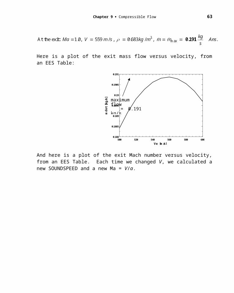
P9.74 Use your strategic ideas, from part (b) of Prob. P9.40, to actually carry out the calculations for mass flow of steam, with po = 300 kPa and To = 600 K, discharging through a converging nozzle of choked exit area 5 cm2. Take advantage of the new EES thermodynamic function SPEEDSOUND(Steam, p = p1, s = s1).
Solution: Using EES for real steam, we don’t have these nice power-law formulas, but we can use the energy equation and the continuity equation and the fact that the entropy is constant:
First establish so and ho from the given po and To:
Then guess an exit velocity V, which we know, from Prob. 9.40a, lies somewhere between 500 and 600 m/s. Compute h from energy, then compute =(h, so) from the EES thermophysical functions. This enables us to calculate the (guessed) mass flow = A V. Is it a maximum? Probably not. Keep changing V until you reach a maximum mass flow and a Mach number of 1.0. The final result obtained by the writer is
Here is a plot of the exit mass flow versus velocity, from an EES Table:
Chapter 9 Compressible Flow 51
500 520 540 560 580 600
0.188
0.1885
0.189
0.1895
0.19
0.1905
0.191
Ve [m/s]
md
ot
[k
g/s
]
And here is a plot of the exit Mach number versus velocity, from an EES Table. Each time we changed V, we calculated a new SOUNDSPEED and a new Ma = V/a.
500 520 540 560 580 600
0.875
0.9
0.925
0.95
0.975
1
1.025
1.05
1.075
1.1
Ve [m/s]
Ma
ch
9.75 A double-tank system in Fig. P9.75 has two identical converging nozzles of1-in2 throat area. Tank 1 is very large, and tank 2 is small enough to be in steady-flow equilibrium with the jet from tank 1.
Nozzle flow is isentropic, but entropy changes between 1 and 3 due to jet dissipation in tank 2. Compute the mass flow. (If you give up, Ref. 14, pp. 288–290, has a good discussion.)
maximum flow = 0.191 kg/sat V = 559 m/s
Ma = 1.0 atV = 559 m/s
-----------------------------------------------------------

52 Solutions Manual Fluid Mechanics, Seventh Edition
Fig. P9.75
Solution: We know that 1V1 2V2 from continuity. Since patm is so low, we may assume that the second nozzle is choked, but the first nozzle is probably not choked. We may guess values of p2 and compare the computed values of flow through each nozzle:
9.76 A large reservoir at 20C and 800 kPa is used to fill a small insulated tank through a converging-diverging nozzle with 1-cm2 throat area and 1.66-cm2 exit area. The small tank has a volume of 1 m3 and is initially at 20C and 100 kPa. Estimate the elapsed time when (a) shock waves begin to appear inside the nozzle; and (b) the mass flow begins to drop below its maximum value.
Solution: During this entire time the nozzle is choked, so let’s compute the mass flow:
Meanwhile, a control volume around the small tank reveals a linear pressure rise with time:
We are assuming, for simplicity, that the tank stagnation temperature remains at 293K. Shock waves move into the nozzle when the tank pressure rises above what would occur if the nozzle exit plane were to have a normal shock:
Chapter 9 Compressible Flow 53
Above this tank pressure, the shock wave moves into the nozzle. The time lapse is
Assuming the tank pressure rises smoothly and the shocks do not cause any instability or anything, the nozzle ceases to be choked when ptank rises above a subsonic isentropic exit:
9.77 A perfect gas (not air) expands isentropically through a supersonic nozzle with an exit area 5 times its throat area. The exit Mach number is 3.8. What is the specific heat ratio of the gas? What might this gas be? If po 300 kPa, what is the exit pressure of the gas?
Solution: We must iterate the area-ratio formula, Eq. (9.44), for k:
Ans. (b)
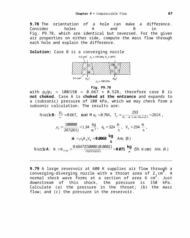
9.78 The orientation of a hole can make a difference. Consider holes A and B in Fig. P9.78, which are identical but reversed. For the given air properties on either side, compute the mass flow through each hole and explain the difference.
54 Solutions Manual Fluid Mechanics, Seventh Edition
Solution: Case B is a converging nozzle
Fig. P9.78
with p2p1 100150 0.667 0.528, therefore case B is not choked. Case A is choked at the entrance and expands to a (subsonic) pressure of 100 kPa, which we may check from a subsonic calculation. The results are:
9.79 A large reservoir at 600 K supplies air flow through a converging-diverging nozzle with a throat area of 2 cm2. A normal shock wave forms at a section of area 6 cm2. Just downstream of this shock, the pressure is 150 kPa. Calculate (a) the pressure in the throat; (b) the mass flow; and (c) the pressure in the reservoir.
Solution: The throat is choked, and just upstream of the shock is a supersonic flow at an area ratio A/A* (6 cm2)/(2 cm2) 3.0. From Table B.1 estimate Ma1 2.64. That is,
(a, c) The pressure ratio across the shock is given by Eq. (9.55) or Table B.2:
Chapter 9 Compressible Flow 55
(b) To avoid bothering with density and velocity, Eq. (9.46b) is handy for choked flow.
9.80 A sea-level automobile tire is initially at 32 lbfin2 gage pressure and 75F. When it is punctured with a hole which resembles a converging nozzle, its pressure drops to 15 lbfin2 gage in 12 min. Estimate the size of the hole, in thousandths of an inch.
Solution: The volume of the tire is 2.5 ft2. With patm 14.7 psi, the absolute pressure drops from 46.7 psia to 29.7 psia, both of which are sufficient to cause a choked exit. A theory for isothermal blowdown of a choked tank was given in Prob. 9.36:
P9.81 Air, at po = 160 lbf/in2 and To = 300F, flows isentropically through a converging- diverging nozzle. At section 1, where A1 = 288 in2, the velocity is V1 = 2068 ft/s. Calculate (a) Ma1; (b) A*; (c) p1; and (d) the mass flow, in slug/s.
Solution: That is a high velocity, 2068 ft/s, even higher than the stagnation speed of sound, ao = (kRTo)1/2 = 1351 ft/s. So the flow at section 1 is supersonic. We need to find Ma1 such that
56 Solutions Manual Fluid Mechanics, Seventh Edition
You could iterate, or EES would find the result in a flash: Ma1 = 2.10 Ans.(a)
(b, c, d) The remaining properties follow from the Mach number:
9.82 Air at 500 K flows through a converging-diverging nozzle with throat area of 1 cm2 and exit area of 2.7 cm2. When the mass flow is 182.2 kgh, a pitot-static probe placed in the exit plane reads po 250.6 kPa and p 240.1 kPa. Estimate the exit velocity. Is there a normal shock wave in the duct? If so, compute the Mach number just downstream of this shock.
Solution: These numbers just don’t add up to a purely isentropic flow. For example, po p 250.6240.1 yields Ma 0.248, whereas AA* 2.7 gives Ma 0.221. If the mass flow is maximum, we can estimate the upstream stagnation pressure:
This doesn’t check with the measured value of 250.6 kPa, nor does an isentropic choked subsonic expansion lead to pexit 240.1—it gives 271 kPa instead. We conclude that there is a normal shock wave in the duct before the exit plane, reducing po:
Chapter 9 Compressible Flow 57
9.83 When operating at design conditions (smooth exit to sea-level pressure), a rocket engine has a thrust of 1 million lbf. The chamber pressure and temperature are 600 lbfin2 absolute and 4000R, respectively. The exhaust gases approximate k 1.38 with a molecular weight of 26. Estimate (a) the exit Mach number and (b) the throat diameter.
Solution: “Design conditions” mean isentropic expansion to pe 14.7 psia 2116 lbfft2:
From Prob. 3.68, if pe pa,
Assuming an isentropic expansion to Mae 3.06, we can compute the throat area:
9.84 Air flows through a duct as in Fig. P9.84, where A1 24 cm2, A2 18 cm2, and A3 32 cm2. A normal shock stands at section 2. Compute (a) the mass flow, (b) the Mach number, and (c) the stagnation pressure at section 3.
Solution: We have enough information at section 1 to compute the mass flow:
Fig. P9.84

58 Solutions Manual Fluid Mechanics, Seventh Edition
Now move isentropically from 1 to 2 upstream of the shock and thence across to 3:
Finally, go back and get the stagnation pressure ratio across the shock:
P9.85 A typical carbon dioxide tank for a paintball gun holds about 12 oz of liquid CO 2. The tank is filled no more than one-third with liquid, which, at room temperature, maintains the gaseous phase at about 850 psia. (a) If a valve is opened that simulates a converging nozzle with an exit diameter of 0.050 in, what mass flow and exit velocity result? (b) Repeat the calculation for helium.
Solution: For CO2, from Table A.4, R = 189 J/kg-K and k = 1.30. By “room temperature” we assume To = 293 K. Convert po = 853 psia = 5.86 MPa. Convert Dexit = 0.050 in = 0.00127 m. Assume an outside pressure of 1 atm, which ensures that the flow through the nozzle will be choked. The maximum mass flow results, Eq. (9.46a), and Vexit = V*, Eq. (9.33):
(b) For helium, from Table A.4, R = 2077 J/kg-K and k = 1.66. Then
9.86 Air enters a 3-cm diameter pipe 15 m long at V1 73 ms, p1 550 kPa, and T1 60C. The friction factor is 0.018. Compute V2, p2, T2, and p02 at the end of the pipe. How much additional pipe length would cause the exit flow to be sonic?
Chapter 9 Compressible Flow 59
Solution: First compute the inlet Mach number and then get (fLD)1:
for which p/p* 5.4554, T/T* 1.1905, V/V* 0.2182, and
Then (fL/D2 14.53 – (0.018)(15)/(0.03) 5.53, read Ma2 0.295
At this new Ma2, read pp* 3.682, TT* 1.179, Then
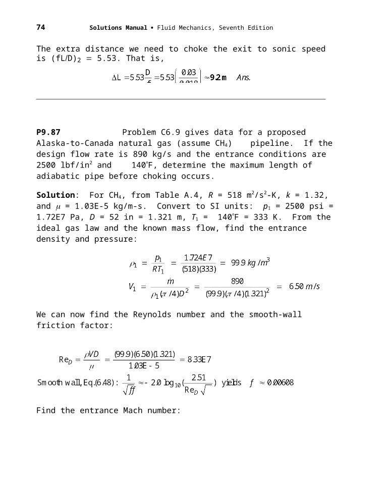
The extra distance we need to choke the exit to sonic speed is (fLD)2 5.53. That is,
P9.87 Problem C6.9 gives data for a proposed Alaska-to-Canada natural gas (assume CH4) pipeline. If the design flow rate is 890 kg/s and the entrance conditions are 2500 lbf/in2 and 140F, determine the maximum length of adiabatic pipe before choking occurs.
Solution: For CH4, from Table A.4, R = 518 m2/s2-K, k = 1.32, and = 1.03E-5 kg/m-s. Convert to SI units: p1 = 2500 psi = 1.72E7 Pa, D = 52 in = 1.321 m, T1 = 140F = 333 K. From the ideal gas law and the known mass flow, find the entrance density and pressure:
60 Solutions Manual Fluid Mechanics, Seventh Edition
We can now find the Reynolds number and the smooth-wall friction factor:
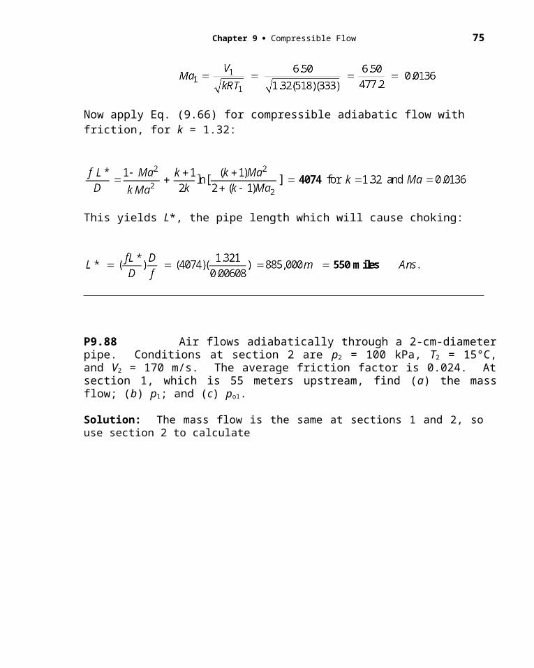
Find the entrance Mach number:
Now apply Eq. (9.66) for compressible adiabatic flow with friction, for k = 1.32:
This yields L*, the pipe length which will cause choking:
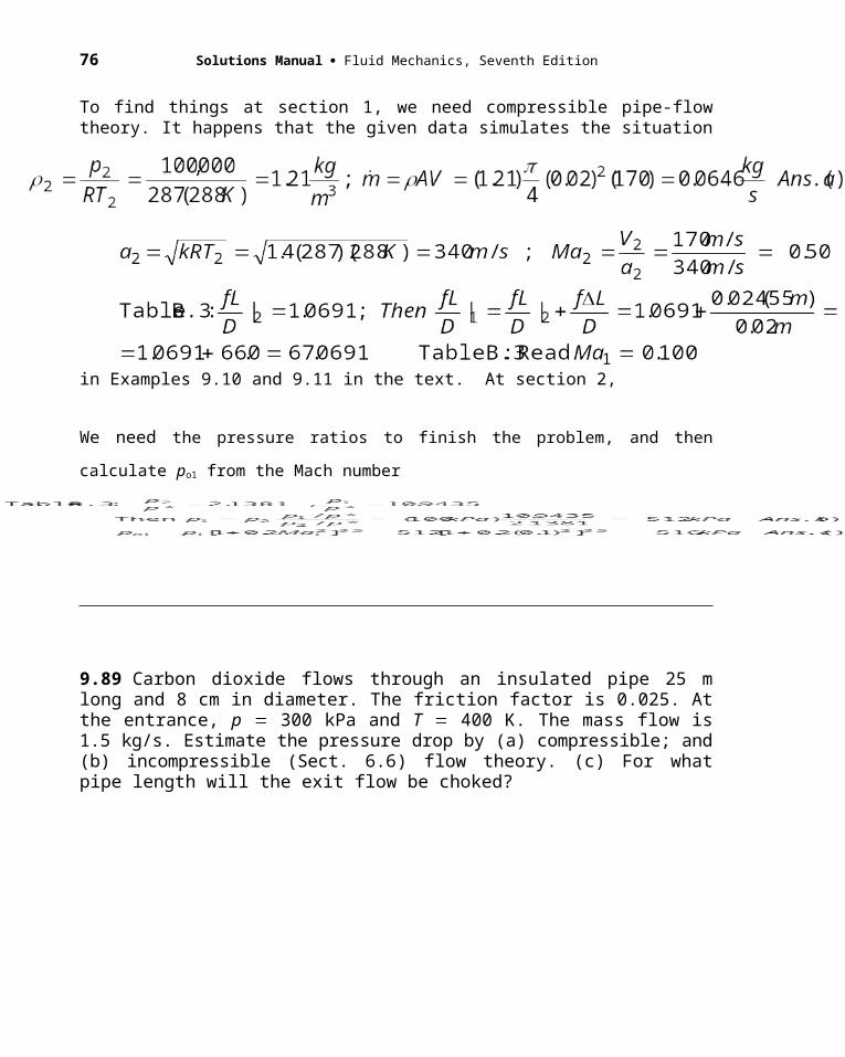
P9.88 Air flows adiabatically through a 2-cm-diameter pipe. Conditions at section 2 are p2 = 100 kPa, T2 = 15°C, and V2 = 170 m/s. The average friction factor is 0.024. At section 1, which is 55 meters upstream, find (a) the mass flow; (b) p1; and (c) po1.
Solution: The mass flow is the same at sections 1 and 2, so use section 2 to calculateTo find things at section 1, we need compressible pipe-flow theory. It happens that the given data simulates the situation in Examples 9.10 and 9.11 in the text. At section 2,
Chapter 9 Compressible Flow 61
We need the pressure ratios to finish the problem, and then calculate po1 from the Mach number
9.89 Carbon dioxide flows through an insulated pipe 25 m long and 8 cm in diameter. The friction factor is 0.025. At the entrance, p 300 kPa and T 400 K. The mass flow is 1.5 kg/s. Estimate the pressure drop by (a) compressible; and (b) incompressible (Sect. 6.6) flow theory. (c) For what pipe length will the exit flow be choked?
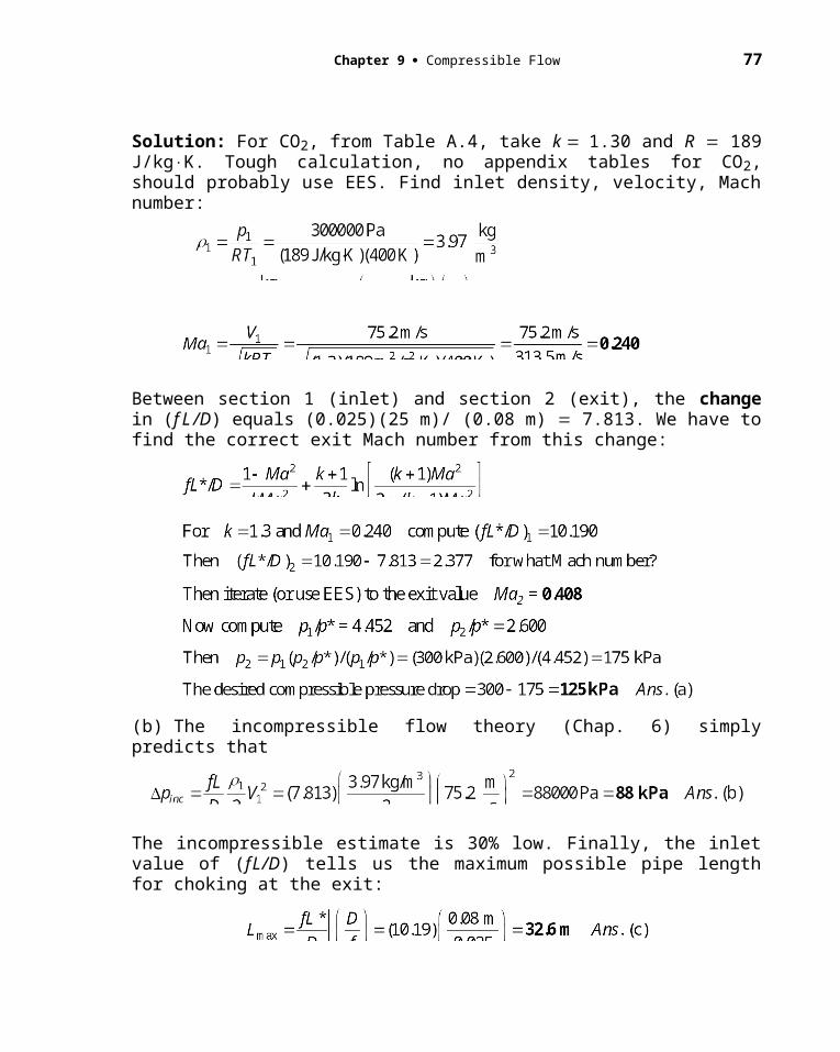
Solution: For CO2, from Table A.4, take k 1.30 and R 189 J/kgK. Tough calculation, no appendix tables for CO2, should probably use EES. Find inlet density, velocity, Mach number:
Between section 1 (inlet) and section 2 (exit), the change in (f L /D) equals (0.025)(25 m)/ (0.08 m) 7.813. We have to find the correct exit Mach number from this change:
62 Solutions Manual Fluid Mechanics, Seventh Edition
(b) The incompressible flow theory (Chap. 6) simply predicts that
The incompressible estimate is 30% low. Finally, the inlet value of (fL/D) tells us the maximum possible pipe length for choking at the exit:
P9.90 Air flows through a rough pipe 120 ft long and 3 inches in diameter. Entrance conditions are p = 90 lbf/in2, T = 68F, and V = 225 ft/s. The flow chokes at the end of the pipe. (a) What is the average friction factor? (b) What is the pressure at the end of the pipe?
Solution: Find the Mach number at the entrance:
Excellent, this Mach number is right in Table B.3. Read fL*/D = 14.5333. Then
Also, in Table B.3, we can read the pressure ratio:
9.91 Air flows steadily from a tank through the pipe in Fig. P9.91. There is a converging nozzle on the end. If the mass flow is 3 kgs and the flow is choked, estimate (a) the Mach number at section 1; and (b) the pressure in the tank.
Chapter 9 Compressible Flow 63
Fig. P9.91
Solution: For adiabatic flow, T* constant To 1.2 3731.2 311K. The flow chokes in the small exit nozzle, D 5 cm. Then we estimate Ma2 from isentropic theory:
Assuming isentropic flow in the inlet nozzle,
P9.92 Air enters a 5-cm-diameter pipe at 380 kPa, 3.3 kg/m3, and 120 m/s. The
friction factor is 0.017. Find the pipe length for which the velocity (a) doubles; (b)
triples; and (c) quadruples.
Solution: First find the conditions at the entrance, which we will call section 1:
(a) Since V* is constant, we simply double (V1/V*) and find the new Mach number:

64 Solutions Manual Fluid Mechanics, Seventh Edition
(b) Again, since V* is constant, we simply triple (V1/V*) and find the new Mach number:
(c) We are already at choking, it is impossible to quadruple the velocity for this flow. Ans.(c)
9.93 Air flows adiabatically in a 3-cm-diameter duct with f 0.015. At the entrance, V 950 ms and T 250 K. How far down the tube will (a) the Mach number be 1.8; and (b) the flow be choked?
Solution: (a) Find the entrance Mach number and its value of fLd:
(b) To go all the way to choking requires the full change
fL1D 0.5222,
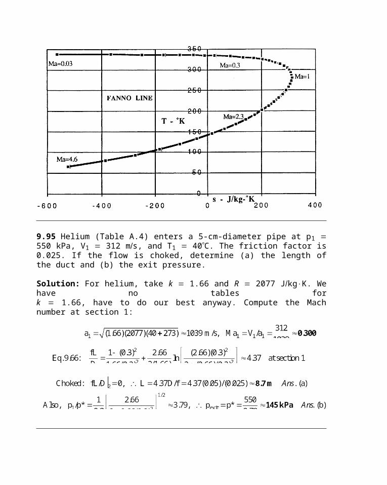
9.94 Compressible pipe flow with friction, Sec. 9.7, assumes constant stagnation enthalpy and mass flow but variable momentum. Such a flow is often called Fanno flow, and a line representing all possible property changes on a temperature-entropy chart is called a Fanno line. Assuming an ideal gas with k 1.4 and the data of Prob. 9.86, draw a Fanno line for a range of velocities from very low to very high Comment on the meaning of the maximum-entropy point on this curve.
Solution: Recall from Prob. 9.86 that, at Section 1 of the pipe, V1 73 ms, p1 550 kPa, and T1 60C 333K, with f 0.018. We can then easily compute Ma1 0.20, 1 5.76 kgm3, Vmax 822 ms, and To 336 K. Our basic algebraic equations are:
(a)
Chapter 9 Compressible Flow 65
(b)
(c)
We simply let V vary from, say, 10 ms to 800 ms, compute from (b) and T from (a) and s from (c), then plot T versus s. [We have arbitrarily set s 0 at state 1.]
The result of this exercise forms the Fanno Line for this flow, shown on the next page. Some Mach numbers are listed, subsonic on the top, supersonic on the bottom, and exactly sonic at the right-hand (maximum-entropy) side. Ans.
9.95 Helium (Table A.4) enters a 5-cm-diameter pipe at p1 550 kPa, V1 312 ms, and T1 40C. The friction factor is 0.025. If the flow is choked, determine (a) the length of the duct and (b) the exit pressure.
Solution: For helium, take k 1.66 and R 2077 JkgK. We have no tables fork 1.66, have to do our best anyway. Compute the Mach number at section 1:
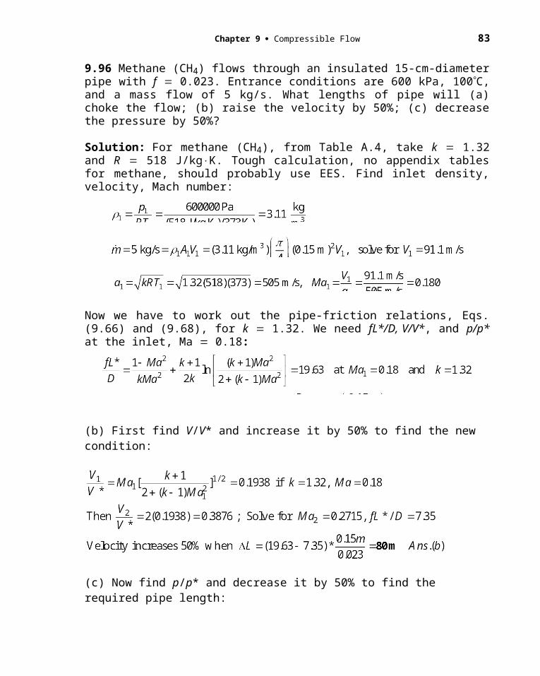
9.96 Methane (CH4) flows through an insulated 15-cm-diameter pipe with f 0.023. Entrance conditions are 600 kPa, 100C, and a mass flow of 5 kg/s. What lengths of pipe will (a) choke the flow; (b) raise the velocity by 50%; (c) decrease the pressure by 50%?
Chapter 9 Compressible Flow 67
Solution: For methane (CH4), from Table A.4, take k 1.32 and R 518 J/kgK. Tough calculation, no appendix tables for methane, should probably use EES. Find inlet density, velocity, Mach number:
Now we have to work out the pipe-friction relations, Eqs. (9.66) and (9.68), for k 1.32. We need fL*/D, V/V*, and p/p* at the inlet, Ma 0.18:
(b) First find V/V* and increase it by 50% to find the new condition:
(c) Now find p/p* and decrease it by 50% to find the required pipe length:
68 Solutions Manual Fluid Mechanics, Seventh Edition
9.97 By making a few algebraic substitutions, show that Eq. (9.74), or the relation in Prob. 9.96, may be written in the density form
Why is this formula awkward if one is trying to solve for the mass flow when the pressures are given at sections 1 and 2?
Solution: This much less laborious algebraic derivation is left as a student exercise. There are two awkward bits: (1) we don’t know 1 and 2; and (2) we don’t know * either, and preliminary computations are necessary.
9.98 Compressible laminar flow, f 64Re, may occur in capillary tubes. Consider air, at stagnation conditions of 100C and 200 kPa, entering a tube 3 cm long and 0.1 mm in diameter. If the receiver pressure is near vacuum, estimate (a) the average Reynolds number, (b) the Mach number at the entrance, and (c) the mass flow in kgh.
Solution: The pipe is choked, “receiver pressure near vacuum,” so L L* and we need only to correctly guess the inlet Mach number and iterate until the Table B.3 value of (fLD) matches the actual value, with f 64Re from laminar pipe theory. Since Re VD and V is constant due to mass conservation, Re varies only due to the change in with temperature (from about 2.1E5 in the entrance to 1.9E5 kgms at the exit). We assume avg 2.0E5 kgms. Try Ma1 from 0.1 to 0.2 and find 0.12 to be the best estimate:
Chapter 9 Compressible Flow 69
9.99 A compressor forces air through a smooth pipe 20 m long and 4 cm in diameter, as in Fig. P9.99. The air leaves at 101 kPa and 200C. The compressor data for pressure rise versus mass flow are shown in the figure. Using the Moody chart to estimate compute the resulting mass flow.
Solution: The compressor performance is approximate by the parabolic relation
Fig. P9.99
We must match this to the pressure drop due to friction in the pipe. For preliminaries, compute e peRTe) 0.744 kgm3, and ae (kRTe) 436 ms. Guess the mass flow:
Then, at the pipe entrance (Sect. 1), we may compute fLD and find the pressure there:
We increase the mass flow until ppipe pcompressor. The final converged result is:
For these operating conditions, the approximate flow rate is 0.256 kgs. Ans.
70 Solutions Manual Fluid Mechanics, Seventh Edition
P9.100 Air flows adiabatically through a pipe 10 cm in diameter and 66 m long. Entrance conditions are p1 = 550 kPa, T1 = 350 K, and V1 = 75 m/s. The average friction factor is 0.022. (a) Is the pipe flow choked at the exit? (b) What is the exit pressure? (c) At what distance down the pipe is the velocity 184 m/s?
Solution: Find the inlet Mach number from the given data:
Excellent, this Mach number is right in Table B.3. Read fL*/D = 14.5333. Then find (fL/D) at the end of the pipe, x = 66 meters:
As close as we can calculate, Yes, it is choked at the exit. Ans.(a)
(b) The exit then must be at (sonic) pressure p*. Calculate this from the inlet pressure:
(c) Go back and find V/V* at the inlet. Then we can move downstream to the new velocity:
9.101 How do the compressible-pipe-flow formulas behave for small pressure drops? Let air at 20C enter a tube of diameter 1 cm and length 3 m. If with p1 102
Chapter 9 Compressible Flow 71
kPa and p2 100 kPa, estimate the mass flow in kgh for (a) isothermal flow, (b) adiabatic flow, and (c) incompressible flow (Chap. 6) at the entrance density.
Solution: For a pressure change of only 2%, all three estimates are nearly the same. Begin by noting that fLD 0.028(3.00.01) 8.4, and 1 102000[287(293)] 1.213 kgm3. Take these estimates in order:
9.102 Air at 550 kPa and 100C enters a smooth 1-m-long pipe and then passes through a second smooth pipe to a 30-kPa reservoir, as in Fig. P9.102. Using the Moody chart to compute f, estimate the mass flow through this system. Is the flow choked?
Fig. P9.102

72 Solutions Manual Fluid Mechanics, Seventh Edition
Solution: Label the pipes “A” and “B” as shown. Given (L/D)A 20 and (L/D)B 40. Label the relevant sections 1, 2, 3, 4 as shown. With po1/pe 550/30 18.3, these short pipes are sure to be choked, with an exit pressure p4 much larger than 30 kPa. One way is to guess Ma1 and work your way through to section 4 to require Ma4 1.0 (choked). Take a constant average viscosity 2.2E5 kg/ms. Assume isentropic expansion to section 1 from the reservoir, frictional flow through pipe A, isentropic expansion from 2 to 3, and a second frictional flow through pipe B to section 4. The correct solution is Ma1 0.18:
Pipe A is so short that the Mach number hardly changes. At (fL/D)2 18.29, read Ma2 0.181. Now, at Ma2 0.181, determine A2/A* 3.26, hence A3/A* (3.26)(3/5)2 1.17, read Ma3 0.613 and (fL/D)3 0.442. Stop to calculate 3 3.49 kg/m3, V3 229 m/s, ReB 1.09E6, from the Moody chart, fB 0.0115. Then (fL/D)4 0.442 – 0.0115(40) 0.018. (?) This last value should have been exactly (fL/D)4 0 if the exit Mach number is 1.0. But we were close. The mass flow follows from the conditions at section 1:
EES can barely improve upon this: Ma1 0.1792, yielding a mass flow of 0.5616 kg/s. The exit pressure is p4 201 kPa, far larger than the receiving reservoir pressure of 30 kPa.
9.103 Natural gas, with k 1.3 and a molecular weight of 16, is to be pumped through 100 km of 81-cm-diameter pipeline. The downstream pressure is 150 kPa. If the gas enters at 60C, the mass flow is 20 kgs, and , estimate the required entrance pressure for (a) isothermal flow and (b) adiabatic flow.
Chapter 9 Compressible Flow 73
Solution: The gas constant is Rgas 831416 520 JkgK. First use Eq. 9.73:
Part (a) indicates a low inlet Mach number, 0.02, so Te To, ae ao 475 m/s. Then use Eqs. (9.74) and (9.75)—the latter simply indicates that the bracket [] 1.000. Then
9.104 A tank of oxygen (Table A.4) at 20C is to supply an astronaut through an umbilical tube 12 m long and 1.5 cm in diameter. The exit pressure in the tube is 40 kPa. If the desired mass flow is 90 kg/h and f 0.025, what should be the air pressure in the tank?
Solution: For oxygen, from Table A.4, take k 1.40 and R 260 J/kgK. Given To 293 K and fL/D (0.025)(12 m)/(0.015 m) 20. Use isothermal flow, Eq. (9.73), as a first estimate:
74 Solutions Manual Fluid Mechanics, Seventh Edition
This is a very good estimate of p1, but we really need adiabatic flow, Eqs. (9.66) and (9.68a). First estimate the entrance Mach number from p1 and T1 To:
We can guess Ma1 around 0.17, find (fL*/D)1, subtract (fL/D) 20, find the new Mach number and p*, thence back up to obtain p1. Iterate to convergence. For example:
Ma1 0.17, (fL*/D)1 21.12, p1/p* 6.43, (fL*/D)2 21.12 – 20 1.12, compute
Ma2 0.49, p2/p* 2.16, p* 40000/2.16 18500 Pa, p1 6.43(18500) 119000 Pa,
T1 To /[1 0.2(0.17)2] 291 K, 1 1.57 kg/m3, mass flow 1AV1 55 kg/h
The mass flow is too low, so try Ma1 a little higher. The iteration is remarkably sensitive to Mach number because the correct exit flow is close to sonic. The final converged solution is
Ma1 0.1738, Ma2 0.7792, p1 189.4 kPa Ans.
This problem is clearly well suited to EES, which converges rapidly to the final pressure.
P9.105 Modify Prob. P9.87 as follows. The pipeline will not be allowed to choke. It will have pumping stations about every two hundred miles. (a) Find the length of pipe for
which the pressure has dropped to 2000 lbf/in2. (b) What is the temperature at that point?
Solution: From Prob. P9.87, we found the following data. For CH4, from Table A.4, R = 518 m2/s2-K, k = 1.32, and = 1.03E-5 kg/m-s. Convert to SI units: p1 = 2500 psi = 1.72E7 Pa, D = 52 in = 1.321 m, T1 = 140F = 333 K. From the ideal gas law and the known mass flow (890 kg/s), find the entrance density and pressure, Reynolds number, and smooth-wall friction factor:
Then we found the entrance Mach number and thus the factor (fL*/D):
Chapter 9 Compressible Flow 75
The present problem involves pressures and temperatures, so we need to calculate p/p* and T/T*:
(a) When the pressure p2 drops to 2000 psia = 1.39E6 Pa, the new pressure ratio will be
(b) At this same Ma2 = 0.0170, compute T2/T* also equals 1.16, same as T1/T*. Therefore the temperature has hardly changed at all:
T2 333K = 140F. Ans.(b)
*P9.106 Air, from a 3 cubic meter tank initially at 300 kPa and 200C, blows down
adiabatically through a smooth pipe 1 cm in diameter and 2.5 m long. Estimate the time
required to reduce the tank pressure to 200 kPa. For simplicity, assume constant tank
temperature and f 0.020.
t = 0: 200C300 kPa 3 m3
Fig. P9.106pa = 100 kPa
(1 (2)
76 Solutions Manual Fluid Mechanics, Seventh Edition
Solution: We know that p2 at the exit is 100 kPa, and we are given f = 0.020, thanks!
For the given L and D, we can immediately calculate fL/D = (0.02)(2.5m/0.01m) =
5.0. Suggested procedure: Calculate the mass flow at ptank = 300 and 200 kPa and
average these two. Guess Ma2 at the exit, calculate fL/D2, increase upstream by 5.0 to
fL/D1, find Ma1 and p1 when po1 = ptank, estimate 1, V1, and the mass flow. To start, guess
sonic flow at the exit, Ma2 = 1.0, fL/D2 = 0. Then fL/D1 = 5.0, for which Ma1 = 0.3066
(Table B.3), p1/p* = 3.54, hence p1 = 354 kPa and po1 = 378 kPa, too high! So the exit
Mach numbers are less than 1.0. Iteration (with EES) leads to the following results that
converge to a tank pressure of 300 kPa:
Repeat these (laborious) calculations for a tank pressure of 200 kPa:
Now, with inlet conditions known, find V1 and 1 and thus the two mass flows:
Tank at 300 kPa: m = [po/RTo](Vol) = [(300000/287/473)kg/m3](3m3) = (2.21)(3) = 6.63 kg
Tank at 200 kPa: m = [po/RTo](Vol) = [(200000/287/473)kg/m3](3m3) = (473)(3) = 4.42 kg
Time to blow down from 300 to 200 kPa = (6.63-4.42 kg)/(0.0179 kg/s) 91 s Ans.
9.107 A fuel-air mixture, assumed equivalent to air, enters a duct combustion chamber at V1 104 m/s and T1 300 K. What amount of heat addition in kJ/kg will cause the
Chapter 9 Compressible Flow 77
exit flow to be choked? What will be the exit Mach number and temperature if 504 kJ/kg is added during combustion?
Solution: Evaluate stagnation temperature and initial Mach number:
A heat addition of 504 kJ/kg is (just barely) less than maximum, should nearly choke:
Finally, without using Table B.4,
9.108 What happens to the inlet flow of Prob. 9.107 if the combustion yields 1500 kJ/kg heat addition and po1 and To1 remain the same? How much is the mass flow reduced?
Solution: The flow will choke down to a lower mass flow such that
9.109 A jet engine at 7000-m altitude takes in 45 kg/s of air and adds 550 kJ/kg in the combustion chamber. The chamber cross section is 0.5 m2, and the air enters the chamber at 80 kPa and 5°C. After combustion the air expands through an isentropic converging nozzle to exit at atmospheric pressure. Estimate (a) the nozzle throat diameter, (b) the nozzle exit velocity, and (c) the thrust produced by the engine.
78 Solutions Manual Fluid Mechanics, Seventh Edition
Fig. P9.109
Solution: At 700-m altitude, pa 41043 Pa, Ta 242.66 K to use as exit conditions.
With data now known at section 2, expand isentropically to the atmosphere:
9.110 Compressible pipe flow with heat addition, Sec. 9.8, assumes constant momentum (p V2) and constant mass flow but variable stagnation enthalpy. Such a flow is often called Rayleigh flow, and a line representing all possible property changes on an temperature-entropy chart is called a Rayleigh line. Assuming air passing through the flow state p1 548 kPa, T1 588 K, V1 266 m/s, and A 1 m2, draw a Rayleigh
Chapter 9 Compressible Flow 79
curve of the flow for a range of velocities from very low to very high Comment on the meaning of the maximum-entropy point on this curve.
Solution: First evaluate the Mach number and density at the reference state:
Our basic algebraic equations are then:
Momentum: p V2 548000 3.25(266)2 778000 (a)
Continuity: V 3.25(266), or: 864/V (b)
Entropy: s 718 ln(T/588) 287 ln( /3.25) (c)
We simply let V vary from, say, 10 m/s to 800 m/s, compute from (b), p from (a), T p/T, and s from (c), then plot T versus s. [We have arbitrarily set s 0 at state 1.]
The result of this exercise forms the Rayleigh Line for this flow, shown below. Some Mach numbers are listed, subsonic on the top, supersonic on the bottom, and exactly sonic at the right-hand (maximum-entropy) side. Ans.
80 Solutions Manual Fluid Mechanics, Seventh Edition
*9.111 Add to your Rayleigh line of Prob. 9.110 a Fanno line (see Prob. 9.94) for stagnation enthalpy equal to the value associated with state 1 in Prob. 9.110. The two curves will intersect at state 1, which is subsonic, and also at a certain state 2, which is supersonic. Interpret these two cases vis-a-vis Table B.2.
Solution: For T1 588 K and V1 266 m/s, the stagnation temperature is
(d)
(c)
Chapter 9 Compressible Flow 81
By varying V and computing (T, , s) from (b, c, d), we plot the Fanno line and add it to the previous Rayleigh line. The composite graph is as follows:
The subsonic intersection is state 1, Ma1 0.55, T2 588 K, and the supersonic intersection is at Ma2 2.20, where, for example, T2 316 K. Also, s1 s2. These two points thus correspond to the two sides of a normal shock wave, where “2” is the supersonic upstream and “1” the subsonic downstream condition. We may check these results in Table B-2, where, at Ma 2.20, the temperature ratio across the shock is1.857—for our calculations, this ratio is 588 K/316 K 1.86 (agreement would be perfect if we kept more significant figures). Shock flow satisfies all the four equations of Rayleigh and Fanno flow combined—continuity, momentum, energy, and the equation of state.
9.112 Air enters a duct subsonically at section 1 at 1.2 kg/s. When 650 kW of heat is added, the flow chokes at the exit at p2 95 kPa and T2 700 K. Assuming frictionless heat addition, estimate (a) the velocity; and (b) the stagnation pressure at section 1.
Solution: Since the exit is choked, p2 p* and T2 T* and, of course, Ma2 1.0. Then
82 Solutions Manual Fluid Mechanics, Seventh Edition
9.113 Air enters a constant-area duct at p1 90 kPa, V1 520 m/s, and T1 558°C. It is then cooled with negligible friction until it exists at p2 160 kPa. Estimate (a) V2; (b) T2; and (c) the total amount of cooling in kJ/kg.
Solution: We have enough information to estimate the inlet Ma1 and go from there:
We have to back off to section 1 to determine the critical (*) values of T, V, To:
Chapter 9 Compressible Flow 83
P9.114 The scramjet of Fig. 9.30 operates with supersonic flow throughout. An idealized sketch is in Fig. C9.8, at the end of this chapter. Assume that the heat addition of 500 kJ/kg, between sections 2 and 3, is frictionless and at constant area of 0.2 m2. Given
Ma2 = 4.0, p2 = 260 kPa, and T2 = 420 K. Assume airflow at k = 1.40. At the combustion section exit, find (a) Ma3, (b) p3, and (c) T3.
Solution: Use frictionless heat-addition theory to get from section 2 to section 3:
Now find the new stagnation temperature ratio and hence the properties at section 3:
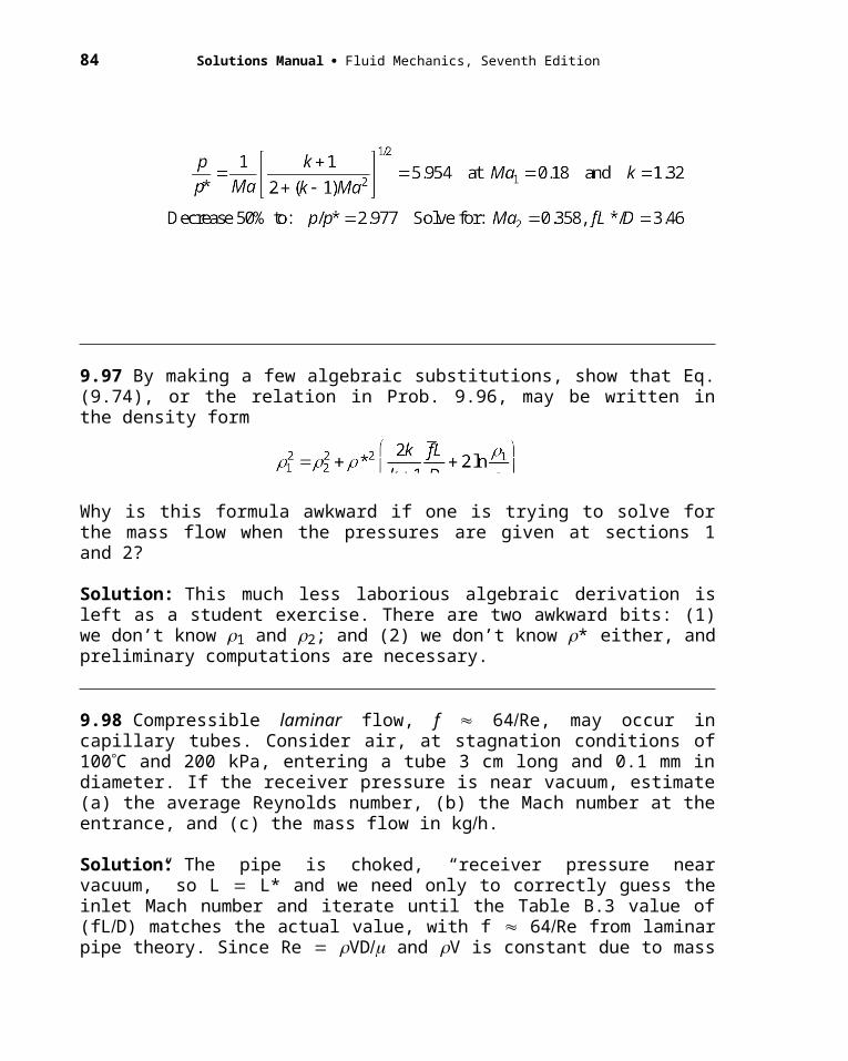
84 Solutions Manual Fluid Mechanics, Seventh Edition
P9.115 Air enters a 5-cm-diameter pipe at 380 kPa, 3.3 kg/m3, and 120 m/s. Assume
frictionless flow with heat addition. Find the amount of heat addition for which the
velocity (a) doubles; (b) triples; and (d) quadruples.
Solution: First find the conditions at the entrance, which we will call section 1:
Since V1 is less than one-fifth of V*, it looks like we can make it up to quadruple
velocity:
Note that we could even quintuple, going up to 5.25V1 before choking due to heat addition.
9.116 An observer at sea level does not hear an aircraft flying at 12000 ft standard altitude until it is 5 statute miles past her. Estimate the aircraft speed in ft/sec.
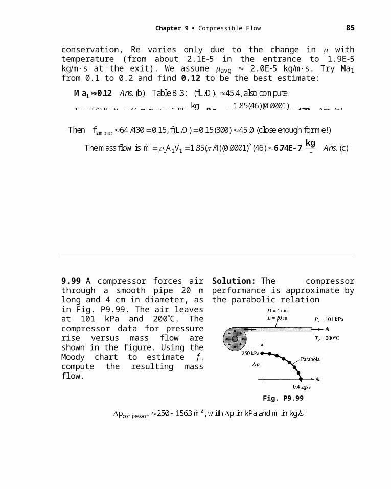
Chapter 9 Compressible Flow 85
Fig. P9.116
Solution: The average temperature over this range is 498°R, hence
P9.117 A tiny scratch in the side of a supersonic wind tunnel creates a very weak wave
of angle 17, as shown in Fig. P9.117, after which a normal shock occurs. The air
temperature in region (1) is 250 K. Estimate the temperature in region (2).
Solution: The weak wave is a Mach wave, hence the Mach number in region 1 is Ma1 = 1/sin(17) = 3.42. The normal shock relations, Table B.2 or Eq. (9.58), thus give the temperature ratio:
9.118 A particle moving at uniform velocity in sea-level standard air creates the two disturbance spheres shown in Fig. P9.118. Compute the particle velocity and Mach number.
Solution: If point “a” represents t 0 units, the particle reaches point “b” in 8 3 5 units. But the distance from a to b is only 3 units. Therefore the (subsonic) Mach number is
17o
shock
1 2
Fig. P9.117

86 Solutions Manual Fluid Mechanics, Seventh Edition
Fig. P9.118
Chapter 9 Compressible Flow 87
9.119 The particle in Fig. P9.119 is moving supersonically in sea-level standard air. From the two disturbance spheres shown, compute the particle (a) Mach number; (b) velocity; and (c) Mach angle.
Fig. P9.119
Solution: If point “a” represents t 0 units, the particle reaches point “b” in 8 – 3 5 units. But the distance from a to b is 8 8 3 19 units. Therefore the Mach number is
9.120 The particle in Fig. P9.120 is moving in sea-level standard air. From the two disturbance spheres shown, estimate(a) the position of the particle at this instant; and (b) the temperature in °C at the front stagnation point of the particle.
Solution: Given sea-level temperature 288 K. If point “a” represents t 0 units, the
Fig. P9.120
particle reaches point “b” in 6 – 3 3 units. But the distance from a to b is 6 units. Therefore the particle Mach number is
9.121 A thermistor probe, in the shape of a needle parallel to the flow, reads a static temperature of –25°C when inserted in the stream. A conical disturbance of half-angle 17° is formed. Estimate (a) the Mach number; (b) the velocity; and (c) the stagnation tem-perature of the stream.
Fig. P9.121

88 Solutions Manual Fluid Mechanics, Seventh Edition
Solution: If the needle is “very thin,” it reads the stream static temperature, T –25°C 248 K. We are given the Mach angle, 17°, so everything else follows readily:
9.122 Supersonic air takes a 5° compres-sion turn, as in Fig. P9.122. Compute the downstream pressure and Mach number and wave angle, and compare with small-disturbance theory.
Solution: From Fig. 9.23, 25°, and we can iterate Eq. (9.86) to a closer estimate:
Fig. P9.122
This is a small deflection. The linear theory of Eqs. 9.88 and 9.89 is reasonably accurate:
P9.123 The 10 deflection in Ex. 9.17 caused a final Mach number of 1.641 and a pressure ratio of 1.707. Compare this with the case of the flow passing through two 5 deflections. Comment on the results and why they might be higher or lower in the second case.
Chapter 9 Compressible Flow 89
Solution: The sketch shows boththe intermediate and the final states.The final Mach number is slightlyhigher, Ma = 1.649. The finalpressure is slightly lower, 1.706.They are close to the 10 case becauseten degrees is small, nearly isentropic.Comment: The closer the flow is toisentropic, the higher the final Mach number and the lower the pressure.
9.124 When a sea-level air flow approaches a ramp of angle 20, an oblique shock wave forms as in Figure P9.124. Calculate (a) Ma1; (b) p2; (c) T2 ; and (d) V2.
Solution: For sea-level air, take p1 101.35 kPa, T1 288.16 K, and 1 1.2255 kg/m3. (a) The approach Mach number is
Fig. P9.12
determined by the specified angles, 60and 20. From Fig. 9.23 we read that Ma1 is slightly less than 2.0. More accurately, use Eq. (9.86):
Iterate, or use EES, to find that Ma1 1.87. Ans. (a)
(b, c) With Ma1 known, use Eqs. (9.83a, c) to find p2 and T2:
(d) Finally, to find V2, first find V1 from the approach Mach number, then use Eq. (9.83b):
5
5Ma= 2.0p = 1.0
Ma= 1.821p = 1.315
Ma= 1.649p = 1.706
90 Solutions Manual Fluid Mechanics, Seventh Edition
P9.125 We saw in the text that, for k = 1.40, the maximum possible deflection caused
by an oblique shock wave occurs at infinite approach Mach number and is max = 45.58.
Assuming an ideal gas, what is max for (a) argon; and (b) carbon dioxide?
Solution: In the limit as Ma1 , the normal-velocity ratio across a shock wave, Eq.
(9.58), is
It is this limiting ratio that we use to calculate max for the two gases above, with Eq.
(9.85).
The results, using Table B.4 to determine k, are as follows:
(a) Argon, k = 1.67, r = 3.985: max = 63.392 - 26.608 = 36.78 Ans.(a)
(b) CO2, k = 1.30, r = 7.667: max = 70.142 - 19.858 = 50.28 Ans.(b)
9.126 Consider airflow at Ma1 2.2. Calculate, to two decimal places, (a) the deflection angle for which the downstream flow is sonic; and (b) the maximum deflection angle.
Solution: We are near the peak of the (invisible) curve for Ma1 2.2 in Fig. 9.23. The wave angles are 65, which we guess for finding the sonic downstream condition:
Chapter 9 Compressible Flow 91
9.127 Do the Mach waves upstream of an oblique-shock wave intersect with the shock? Assuming supersonic downstream flow, do the downstream Mach waves intersect the shock? Show that for small deflections the shock-wave angle lies halfway between 1 and 2 for any Mach number.
Fig. P9.127
Solution: Yes, Mach waves both upstream and downstream will intersect the shock:
Thus, to first order (small deflection), the shock wave angle will lie halfway between 1 and ( 2 ), as sketched in the figure above.
9.128 Air flows past a two-dimensional wedge-nosed body as in Fig. P9.128. Determine the wedge half-angle for which the horizontal component of the total pressure force on the nose is 35 kN/m of depth into the paper.
Solution: Regardless of the wedge angle , the horizontal force equals the pressure inside the shock times the projected vertical area of the nose:
Fig. P9.128

92 Solutions Manual Fluid Mechanics, Seventh Edition
9.129 Air flows at supersonic speed toward a compression ramp, as in Fig. P9.129. A scratch on the wall at a creates a wave of 30 angle, while the oblique shock has a 50 angle. What is (a) the ramp angle ; and (b) the wave angle caused by a scratch at b?
Fig. P9.129
Solution: The two “scratches” cause Mach waves which are directly related to Mach No.:
P9.130 A supersonic airflow, at a temperature of 300 K, strikes a wedge and is deflected 12. If the resulting shock wave is attached, and the temperature after the shock is 450 K, (a) estimate the approach Mach number and wave angle. (b) Why are there two solutions?
Solution: We search through the
oblique-shock solutions until we
find a = 12 deflection for which
T2/T1 = 450K/300K = 1.50.
(a, b) There are two solutions, weak and strong:
Ma1 = 4.69 , = 22 (weak shock)
Ma1 = 1.78 , = 80 (strong shock) Answers (a)
9.131 The following formula has been suggested as an alternate to Eq. (9.86) to relate upstream Mach number to the oblique shock wave angle and turning angle :
Ma1
12o
weakshock
strongshock
Fig. P9.130
Chapter 9 Compressible Flow 93
Can you prove or disprove this relation? If not, try a few numerical values and compare with the results from Eq. (9.86).
Solution: The formula is quite correct and serves as an interesting alternative to Eq. (9.86). Notice that one can immediately solve for Ma1 if and are known, which would have been a great help in Prob. 9.124. For details of the proof, see page 371 of R. M. Olson, Essentials of Engineering Fluid Mechanics, 4th ed., Harper and Row, New York, 1980.
9.132 Air flows at Ma 3 and p 10 psia toward a wedge of 16° angle at zero incidence, as in Fig. P9.132. (a) If the pointed edge is forward, what is the pressure at point A? If the blunt edge is forward, what is the pressure at point B?
Solution: For Ma 3, 8°, Eq. 9.86:
Fig. P9.132
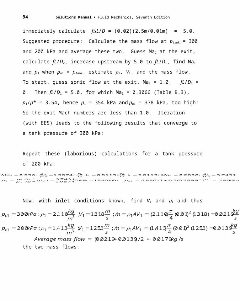
94 Solutions Manual Fluid Mechanics, Seventh Edition
(b) A normal shock forms, and pB po2 inside the shock. Given po1 p1/0.0272 367 psia, Table B.2, Ma 3: po2/po1 0.3283, hence po2 0.3283(367) 121 psia. Ans. (b)
9.133 Air flows supersonically toward the double-wedge system in the figure. The (x,y) coordinates of the tips are given. Both wedges have 15° deflection angles. The shock wave of the forward wedge strikes the tip of the aft wedge. What is the freestream Mach number?
Fig. P9.133
Solution: However tricky the shock reflection might be at the upper (aft) wedge, the problem is solved by knowing the shock angle at the lower (forward) wedge:
9.134 When an oblique shock strikes a solid wall, it reflects as a shock of sufficient strength to cause the exit flow Ma3 to be parallel to the wall, as in Fig. P9.134. For airflow with Ma1 2.5 and p1 100 kPa, compute Ma3, p3, and the angle .
Fig. P9.134
Solution: With 1 40°, we can compute the first shock deflection, which then must turn back the same amount through the second shock:
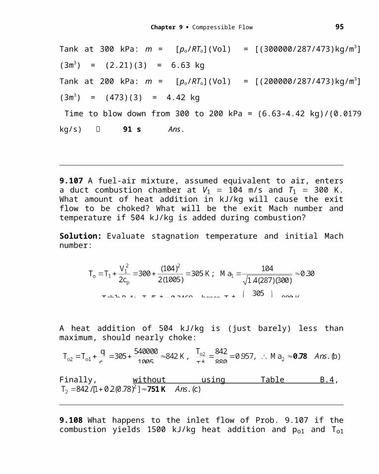
Chapter 9 Compressible Flow 95
9.135 A bend in the bottom of a supersonic duct flow induces a shock wave which reflects from the upper wall, as in Fig. P9.135. Compute the Mach number and pressure in region 3.
Solution: Given 10°, find state 2:
Fig. P9.135
9.136 Figure P9.136 is a special application of Prob. 9.135. With careful design, one can orient the bend on the lower wall so that the reflected wave is exactly canceled by the return bend, as shown. This is a method of reducing the Mach number in a channel (a supersonic diffuser). If the bend angle is 10°, find (a) the downstream width h and (b) the downstream Mach number. Assume a weak shock wave.
Fig. P9.136
Solution: The important thing is to find the angle between the second shock and the upper wall, as shown in the figure. With initial deflection 10°, proceed forward to “3”:
Length CB in the figure (1 m)/sin(24.384°) 2.422 m, angle ACB 14.384°, angle CBA 2 28.096°, by the law of sines, AB/sin(14.384°) 2.422/sin(28.096°) or the length AB 1.278 m. Finally, duct width h 1.278sin(18.096°) 0.40 m. Ans. (a)
The horizontal distance from one lower corner to the next is 3.42 m. The length of CB is 3.47 m. Thus the shocks are not drawn to scale in the figure.
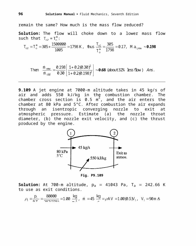
96 Solutions Manual Fluid Mechanics, Seventh Edition
9.137 A 6 half-angle wedge creates the reflected shock system in Fig. P9.137. If Ma3 2.5, find (a) Ma1; and (b) the angle .
Fig. P9.137
Solution: (a) We have to go backward from region 3 to regions 2 and 1, using Eq. (9.86). In both cases the turning angle is 6. EES is of course excellent for this task, otherwise the iteration will be laborious. The results are:
Since the wall is horizontal, it is clear from the geometry of Fig. P9.137 that
9.138 The supersonic nozzle of Fig. P9.138 is overexpanded (case G of Fig. 9.12) with Ae/At 3.0 and a stagnation pressure of 350 kPa. If the jet edge makes a 4° angle with the nozzle centerline, what is the back pressure pr in kPa?
Solution: The nozzle is clearly choked because there are shock waves downstream. Thus
Fig. P9.138
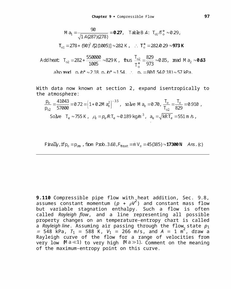
Chapter 9 Compressible Flow 97
9.139 Airflow at Ma 2.2 takes a com-pression turn of 12° and then another turn of angle in Fig. P9.139. What is the maximum value of for the second shock to be attached? Will the two shocks inter-sect for any less than max?
Fig. P9.139
Solution: First get the conditions in section (2) and then iterate for max:
NOTE: The two shocks 1 and 2 always intersect for any 2 max. Ans.
9.140 The solution to Prob. 9.122 is Ma2 2.750 and p2 145.5 kPa. Compare these results with an isentropic compression turn of 5°, using Prandtl-Meyer theory.
Solution: Find for Ma 3 and subtract 5°:
Fig. P9.122
This is almost identical to the shock wave result, because a 5° turn is nearly isentropic.
9.141 Supersonic airflow takes a 5° expansion turn, as in Fig. P9.141. Compute the downstream Mach number and pressure and compare with small-disturbance theory.
Solution: Find for Ma 3 and add 5°:
Fig. P9.141
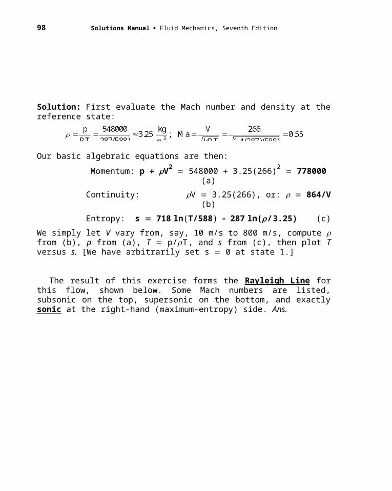
98 Solutions Manual Fluid Mechanics, Seventh Edition
The linear theory is not especially accurate because even a 5° turn is slightly nonlinear:
9.142 A supersonic airflow at Ma1 3.2 and p1 50 kPa undergoes a compression shock followed by an isentropic expansion turn. The flow deflection is 30° for each turn. Compute Ma2 and p2 if (a) the shock is followed by the expansion and (b) the expansion is followed by the shock.
Solution: The solution is given in the form of the two sketches below. A shock wave with a 30° turn is a hugely non-isentropic flow, so the final conditions are nowhere near the original and they do not agree with each other either.
Fig. P9.142
9.143 Airflow at Ma1 3.2 passes through a 25° oblique-shock deflection. What isentropic expansion turn is required to bring the flow back to (a) Ma1 and (b) p1?
Fig. P9.143
Chapter 9 Compressible Flow 99
Solution: First work out state (2):
P9.144 The 10 deflection in Ex. 9.17 caused the Mach number to drop to 1.64. (a) What turn angle will create a Prandtl-Meyer fan and bring the Mach number back up to 2.0?
(b) What will be the final pressure?
Solution: Recall from Ex. 9.17 that the shock wave caused Ma2 = 1.64 and p2 = 17.07 psia. First calculate the (reduced) stagnation pressure in section 2, plus the Prandtl-Meyer angle 2:
Now find the Prandtl-Meyer angle in section 3, knowing that Ma3 = 2.0:
The final wall is just slightly down from horizontal, and the final pressure is just slightly reduced from the original value of 10 psia. The 10 deflection angle is almost isentropic.
10
12 3
Ma1 = 2
p1 = 10 psia
Fig. P9.144
2
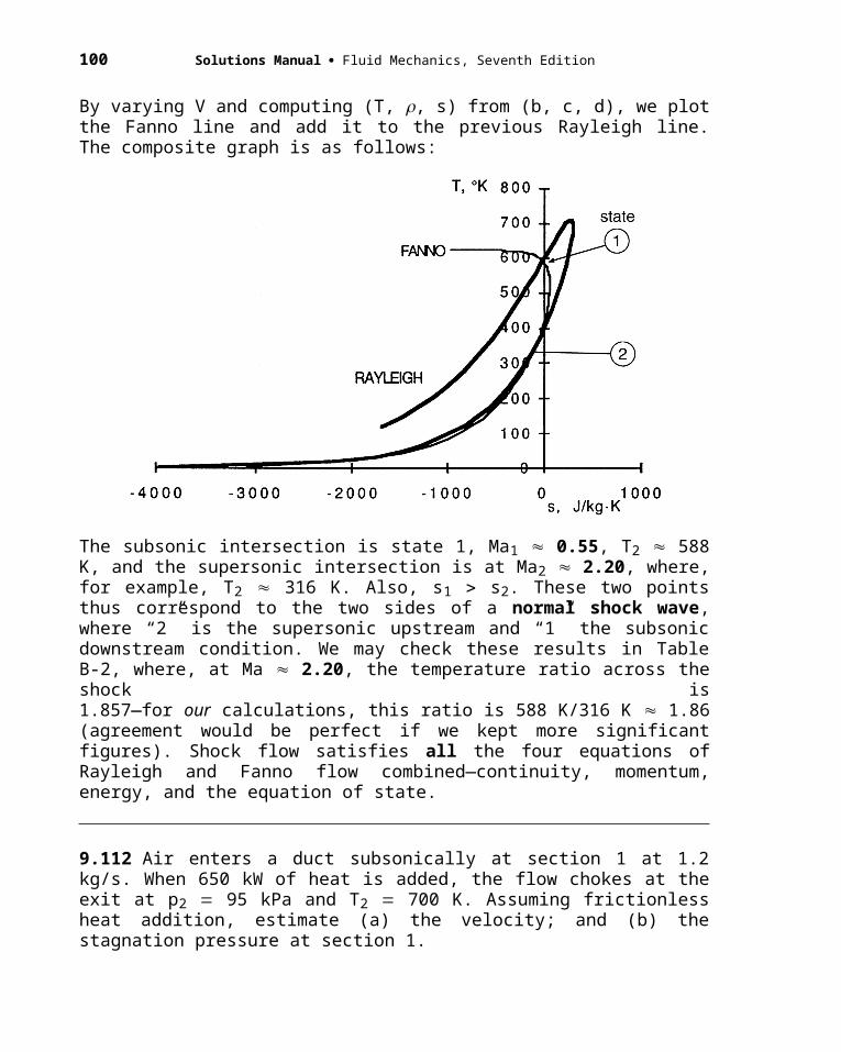
100 Solutions Manual Fluid Mechanics, Seventh Edition
9.145 Air at Ma1 2.0 and p1 100 kPa undergoes an isentropic expansion to a down-stream pressure of 50 kPa. What is the desired turn angle in degrees?
Solution: This is a real ‘quickie’ compared to what we have been doing for the past few problems. Isentropic expansion to a new pressure specifies the downstream Mach number:
9.146 Air flows supersonically over a surface which changes direction twice, as in Fig. P9.146. Calculate (a) Ma2; and (b) p3.
Fig. P9.146
Solution: (a) At the initial condition Ma1 2.0, from Table B.5 read 1 26.38. The first turn is 10, so 2 26.38 10 36.38. From Table B.5 read Ma2 2.38. For more accuracy, use Eq. (9.99) to obtain Ma2 2385. Ans. (a)
(b) The second turn is 12, so 3 36.38 12 48.38. From Table B.5 read Ma3 2.93. For more accuracy, use Eq. (9.99) to obtain Ma2 2.9296. (Not worth the extra effort.) To find pressures, we need the stagnation pressure, which is constant:
Chapter 9 Compressible Flow 101
9.147 A converging-diverging nozzle with a 4:1 exit-area ratio and p0 500 kPa operates in an underexpanded condition (case 1 of Fig. 9.12) as in Fig. P9.147. The receiver pressure is pa 10 kPa, which is less than the exit pressure, so that expansion wavesform outside the exit. For the given conditions, what will the Mach number Ma2 and the angle of the edge of the jet be? Assume k 1.4 as usual.
Solution: Get the Mach number in the exit and then execute a Prandtl-Meyer expansion:
Fig. P9.147
9.148 Air flows supersonically over a circular-arc surface as in Fig. P9.148. Estimate (a) the Mach number Ma2 and (b) the pressure p2 as the flow leaves the circular surface.
Fig. P9.148
102 Solutions Manual Fluid Mechanics, Seventh Edition
Solution: (a) At the initial condition Ma1 2.5, from Table B.5 read 1 39.12.(a) Circular arc or not, the turn angle is 32, so 2 39.12 32 71.12. From Table B.5 read Ma2 4.44. For more accuracy, use Eq. (9.99) to obtain Ma2 4.437. Ans. (a)
(b) To find p2, first find the stagnation pressure:
P9.149 Air flows at Ma = 3.0 past a doubly symmetric diamond airfoil whose front and rear included angles are both 24°. For zero angle of attack, compute the drag coefficient with shock-expansion theory and compare with Ackeret theory.
Solution: The airfoil and its front and rear pressures are shown below.
The foil thickness is C[tan(12)] = 0.2126C. The drag coefficient is:
From Ackeret theory, Eq. (9.107), the drag coefficient prediction is somewhat lower:
Ma = 3.0
24 24
Ma2 = 2.406p2 = 2.3404 p2 = 36.892o Ma3 = 3.653
p3 = 0.0099 p3 = 60.892o
p
Fig. P9.149

Chapter 9 Compressible Flow 103
Ackeret (small-disturbance) theory is 19% low because the airfoil is too thick (21%).
9.150 A flat plate airfoil with chord C 1.2 m is to have a lift of 30 kN/m when flying at 5000-m standard altitude with U 641 m/s. Using Ackeret theory, estimate (a) the angle of attack; and (b) the drag force in N/m.
Solution: At 5000 m, 0.7361 kg/m3, T 256 K, and p 54008 Pa. Compute Ma:
With angle of attack known, Ackeret theory simply predicts that
9.151 Air flows at Ma 2.5 past a half-wedge airfoil whose angles are 4, as in Fig. P9.151. Compute the lift and drag coefficients at equal to (a) 0; and (b) 6.
Solution: Let’s use Ackeret theory here:
Fig. P9.151
[A complete shock-expansion calculation gives CL –0.0065, CD 0.00428.]
[A complete shock-expansion calculation gives CL 0.179, CD 0.0219.]
104 Solutions Manual Fluid Mechanics, Seventh Edition
P9.152 The X-43 model A scramjet aircraft in Fig. 9.30 is small, W = 3000 lbf, and unmanned, only 12.33 ft long and 5.5 ft wide. The aerodynamics of a slender arrowhead-shaped hypersonic vehicle is beyond our scope. Instead, let us assume it is a flat plate airfoil of area 2.0 m2. Let Ma = 7 at 12,000 m standard altitude. Estimate the drag, by shock-expansion theory. [HINT: Use Ackeret theory to estimate the angle of attack.]
Solution: From Table B.6 at 12,000 m,p1 = 19312 Pa and T1 = 216.66 K.Knowing W = 3000 lbf = 13345 N,we can estimate CL = W/[0.5kpMa12] = (13345N)/[0.5(1.4)(19312)(7)2(2.0)] = 0.0101.Use Ackeret theory, Eq. (9.104), to estimate :
CL = 0.0101 = 4/(Ma2 – 1)1/2 , solve for 1.0 degree.
Assume = 1 degree, as in the figure. From shock theory, Eqs. (9.86) and (9.83a), calculate
Ma2 = 5.582, =8.848, p2/p = 1.186, p2= 1.186(19312) = 22902 Pa
The Prandtl-Meyer expansion is on the top, with a turning angle of 1 degree. From Eq. (9.99),
The (hypothesized) wing area is 2.0 m2. The total force, lift, and drag of the flat plate is thus
We could iterate, but we are already within 0.3% of the correct lift. Ackeret theory was surprisingly accurate for such a high Mach number, because of the very small deflection.
p2 = 22902 Pa
Ma1 = 7
= 1 p3 = 16209 Pa
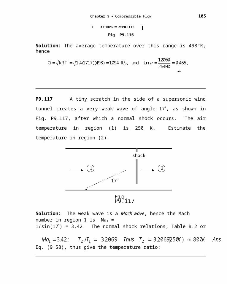
Chapter 9 Compressible Flow 105
9.153 A supersonic transport has a mass of 65 Mg and cruises at 11-km standard altitude at a Mach number of 2.25. If the angle of attack is 2 and its wings can be approximated by flat plates, estimate (a) the required wing area; and (b) the thrust.
Solution: At 11 km (Table B.6), take p 22612 Pa. (a) Use linearized theory:
(b) According to linearized (Ackeret) theory, if there is no thickness drag, then
9.154 A symmetric supersonic airfoil has its upper and lower surfaces defined by a sine waveshape:
where t is the maximum thickness, which occurs at x C/2. Use Ackeret theory to derive an expression for the drag coefficient at zero angle of attack. Compare your result with Ackeret theory for a symmetric double-wedge airfoil of the same thickness.
Solution: Evaluate the mean-square surface slope and then use Eq. (9.107):
Meanwhile, for a double-wedge of the same thickness t, from Prob. 9.152,
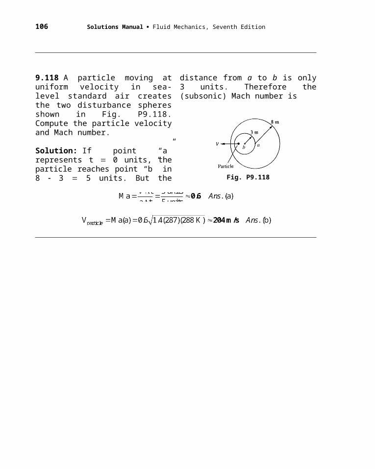
106 Solutions Manual Fluid Mechanics, Seventh Edition
P9.155 The F-35 airplane in Fig. 9.29 has a wingspan of 10 m and a wing area of 41.8 m2. It cruises at about 10 km altitude with a gross weight of about 200 kN. At that altitude, the engine develops a thrust of about 50 kN. Assume the wing has a symmetric diamond airfoil with a thickness of 8%, and accounts for all lift and drag. Estimate the cruise Mach number of the airplane. For extra credit, explain why there are two solutions.
Solution: At 10 km standard altitude, from Table B.6, = 0.4125 kg/m3, and
atmospheric pressure is p = 26416 Pa. We need to match lift and drag to the given
weight/thrust data:
For a symmetric 8% diamond airfoil, as in Fig. E9.21, the slope everywhere is |dy/dx| =
0.08, so the numbers for lift and drag are as follows:
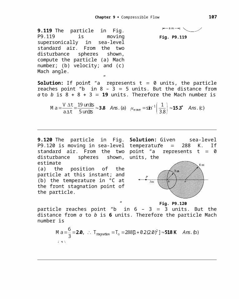
Chapter 9 Compressible Flow 107
to be solved for and Ma. It was a bit of a surprise to the writer that there are two
solutions to this system, both quite realistic:
(1) High velocity, low lift coefficient: = 0.02895 rad (1.66), Ma = 1.90 Ans.(1)
(2) Low velocity, high lift coefficient: = 0.02895 rad (1.66), Ma = 1.176 Ans.(2)
NOTE: The true Mach number of the F-35A would include drag and lift of the fuselage and tail.
EXTRA CREDIT: Why are there two solutions? Because the lift and drag vary as
Ma2/(Ma2-1)1/2, which, for a given , comes down and then back up again, like this:
To match both lift and drag requires = 0.02895 radians, then solving the lift as a quadratic equation yields the two solutions, Ma = 1.176 and 1.900. COMMENT: Ma = 1.176 is close to the transonic regime, for which Ackeret theory falters.
9.156 A thin circular-arc airfoil is shown in Fig. P9.156. The leading edge is parallel to the free stream. Using linearized (small-turning-angle) supersonic-flow theory, derive a formula for the lift and drag co-efficient for this orientation, and compare
with Ackeret-theory results for an angle of attack tan–1(h/L).
Solution: For the (x,y) coordinate system shown, the formula for the plate surface is
Fig. P9.155
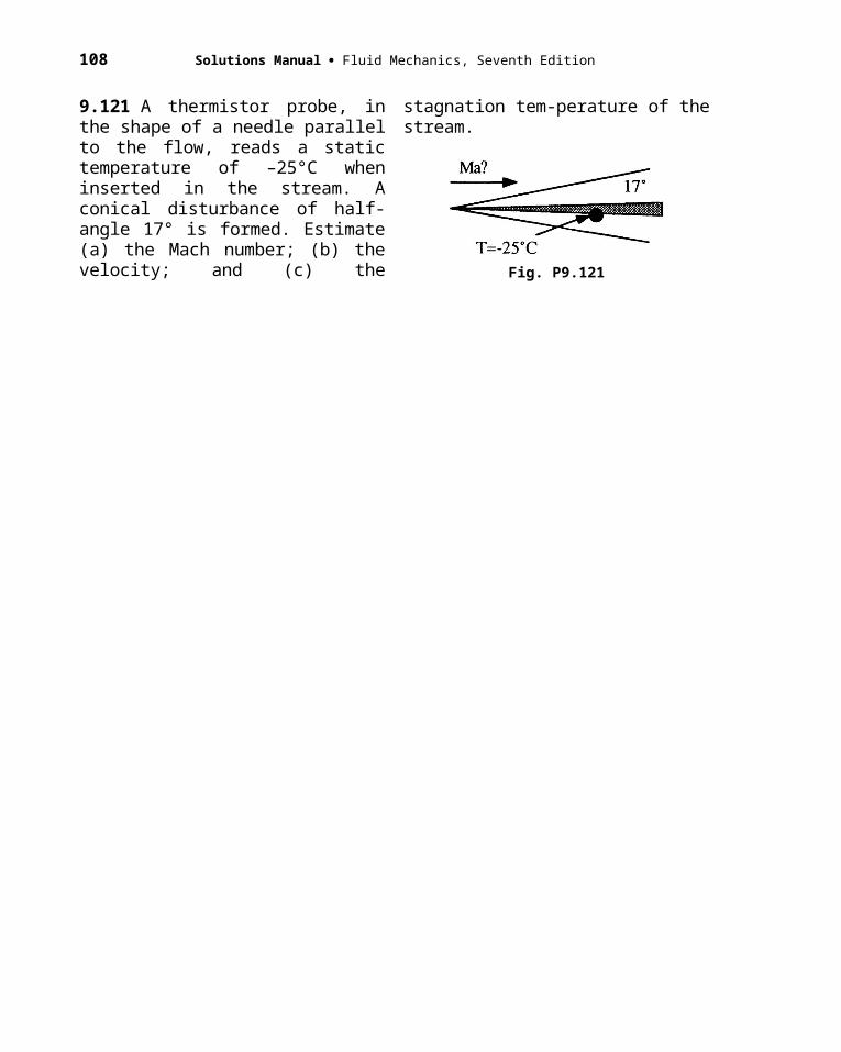
108 Solutions Manual Fluid Mechanics, Seventh Edition
Fig. P9.156
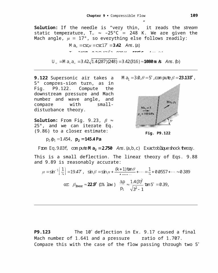
If (small disturbances), Since the flow approaches parallel to the leading edge, the pressure distribution on the airfoil looks like the bottom figure on the previous page. We compute this pressure distribution from the linearized expression, Eq. (9.89):
Carry out this integration, assuming that h chord length C L, to obtain
But h/L radians, therefore which is exactly Ackeret theory.
This is exactly the same as Ackeret theory. The extra term “1/3” is the “thickness-drag” contribution (actually the camber slope contribution) from Eqs. (9.106, 107) of the text.
P9.157 The Ackeret airfoil theory of Eqs. (9.104-5) is meant for moderate supersonic
speeds, 1.2 < Ma < 4. How does it fare for hypersonic speeds? To illustrate, calculate
(a) CL and (b) CD for a flat-plate airfoil at = 5, with Ma = 8.0, using shock-expansion
theory, and compare with Ackeret theory. Comment.
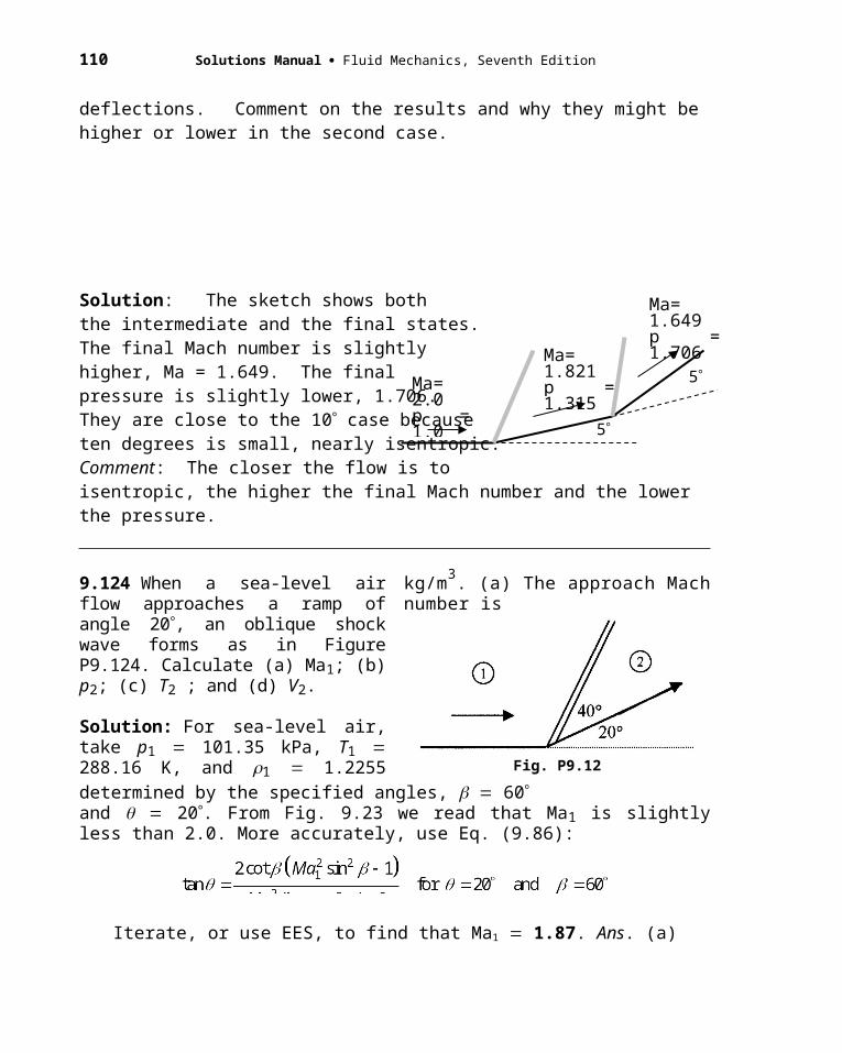
110 Solutions Manual Fluid Mechanics, Seventh Edition
Solution: Like Example 9.19, we need only calculate a (steep) shock wave on the
bottom and a (steep) expansion wave fan on the top. The results are shown in the figure
below.
If the airfoil has length C and span b, the force on the plate is F = (p2 - p3)bC. Then we
compute Lift = F cos and Drag = F sin . The two force coefficients are:
If we apply Ackeret theory to the same data, we obtain, much more simply,
Even at hypersonic Mach numbers, Ackeret theory is not bad – and temptingly simple!
The theory is helped here by the fact that the angle of attack and foil thickness are small.
= 5
Ma=8.0, p
= 10.85p2 = 2.4771 pFig. P9.157
Ma3 = 9.412p3 = 0.3442 p
shock
expansion waves

Chapter 9 Compressible Flow 111
FUNDAMENTALS OF ENGINEERING EXAM PROBLEMS: Answers
In the following problems, assume one-dimensional flow of ideal air, R 287 J/(kgK) and k 1.4.
FE9.1 For steady isentropic flow, if the absolute temperature increases 50%, by what ratio does the static pressure increase?
(a) 1.12 (b) 1.22 (c) 2.25 (d) 2.76 (e) 4.13FE9.2 For steady isentropic flow, if the density doubles, by what ratio does the static pressure increase?
(a) 1.22 (b) 1.32 (c) 1.44 (d) 2.64 (e) 5.66FE9.3 A large tank, at 500 K and 200 kPa, supplies isentropic air flow to a nozzle. At section 1, the pressure is only 120 kPa. What is the Mach number at this section?
(a) 0.63 (b) 0.78 (c) 0.89 (d) 1.00 (e) 1.83FE9.4 In Prob. FE9.3 what is the temperature at section 1?
(a) 300 K (b) 408 K (c) 417 K (d) 432 K (e) 500 KFE9.5 In Prob. FE9.3, if the area at section 1 is 0.15 m2, what is the mass flow?
(a) 38.1 kg/s (b) 53.6 kg/s (c) 57.8 kg/s (d) 67.8 kg/s (e) 77.2 kg/sFE9.6 For steady isentropic flow, what is the maximum possible mass flow through the duct in Fig. FE9.6? (To 400 K, po 300 kPa)
(a) 9.5 kg/s (b) 15.1 kg/s (c) 26.2 kg/s (d) 30.3 kg/s (e) 52.4 kg/s
Fig. FE9.6
FE9.7 If the exit Mach number in Fig. FE9.6 is 2.2, what is the exit area?(a) 0.10 m 2 (b) 0.12 m2 (c) 0.15 m2 (d) 0.18 m2 (e) 0.22 m2
FE9.8 If there are no shock waves and the pressure at one duct section in Fig. FE9.6 is 55.5 kPa, what is the velocity at that section?
(a) 166 m/s (b) 232 m/s (c) 554 m/s (d) 706 m/s (e) 774 m/sFE9.9 If, in Fig. FE9.6, there is a normal shock wave at a section where the area is 0.07 m2, what is the air density just upstream of that shock?
(a) 0.48 kg/m3 (b) 0.78 kg/m 3 (c) 1.35 kg/m3 (d) 1.61 kg/m3 (e) 2.61 kg/m3
FE9.10 In Prob. FE9.9, what is the Mach number just downstream of the shock wave?(a) 0.42 (b) 0.55 (c) 0.63 (d) 1.00 (e) 1.76
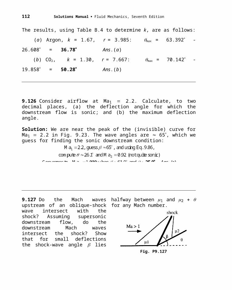
112 Solutions Manual Fluid Mechanics, Seventh Edition
COMPREHENSIVE PROBLEMS
C9.1 The converging-diverging nozzle in the figure has a design Mach number of 2.0 at the exit plane for isentropic flow from tank a to b. (a) Find the exit area Ae and back pressure pb which will allow design conditions. (b) The back pressure grows as tank b fills with air, until a normal shock wave appear in the exit plane. At what back pressure does this occur? (c) If tank b remains at constant T 20°C, how long will it take for the flow to go from condition (a) to condition (b)?
Fig. C9.1
Solution: (a) Compute the isentropic pressure ratio and area ratio for Ma 2.0:
(b) Compute the pressure ratio across a shock for Ma 2.0:
(c) Compute the (constant) mass flow and the mass needed to fill the tank:
Since mass flow is constant, the time required is simply the ratio of these two:
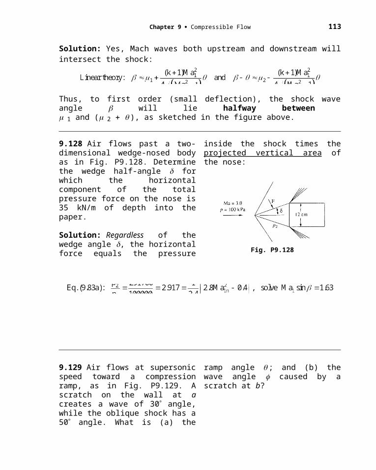
Chapter 9 Compressible Flow 113
C9.2 Two large air tanks, one at 400 K and 300 kPa and the other at 300 K and 100 kPa, are connected by a straight tube 6 m long and 5 cm in diameter. The average friction factor is 0.0225. Assuming adiabatic flow, estimate the mass flow through the tube.
Solution: The higher-pressure tank denotes the inlet stagnation conditions, po 300 kPa and To 400 K. The flow will be subsonic, but we have no idea whether it is choked. Assume that the tube exit pressure equals the receiver pressure, 100 kPa. We must iterate—an ideal job for EES! We do know (f L/D):
If p2 100 kPa, we must ensure that the inlet Mach number is just sufficient that the inlet stagnation pressure po1 300 kPa:
Guess Ma2, back off (fL/D) 2.70, find Ma1, check p*, p1, and po1. Example:
So we back off and try values of Ma2 1.0 and proceed until the inlet matches. The solution (performed by the author using EES) is
So the tube is nearly, but not quite, choked.
C9.3 Fig. C9.3 shows the exit of a converging-diverging nozzle, where an oblique shock pattern is formed. In the exit plane, which has an area of 15 cm2, the air pressure is 16 kPa and the temperature is 250 K. Just outside the exit shock, which makes an angle of 50° with the exit plane, the temperature is 430 K. Estimate (a) the mass flow; (b) the throat area; (c) the turning angle of the exit flow; and, in the tank supplying the air, (d) the pressure and (e) the temperature.
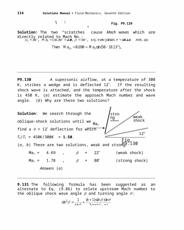
114 Solutions Manual Fluid Mechanics, Seventh Edition
Fig. C9.3
Solution: We know the temperature ratio and the shock wave angle, so we can muddle through oblique-shock-wave theory to find the shock conditions:
With the exit Mach number known, it is easy to compute stagnation conditions:
C9.4 The properties of a dense gas (high pressure and low temperature) are often approximated by van der Waals’ equation state [Refs. 17 and 18]:
Find an analytic expression for the speed of sound of a van der Waals gas. Assuming k = 1.4, compute the speed of sound of air, in ft/s, at –100 F and 20 atm, for (a) a
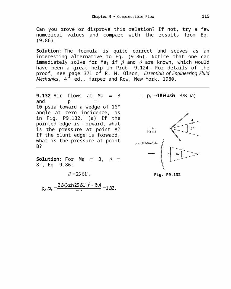
Chapter 9 Compressible Flow 115
perfect gas, and (b) a van der Waals gas. What percentage higher density does the van der Waals relation predict? NOTE: 1 atm = 2116 lbf/ft3.
Solution: For air, take R = 1716 ft-lbf/slugR. First evaluate the densities, T = 360R:
The van der Waals relation predicts air density 5.7% higher.
(a) For an ideal gas,
(b) For the van der Waals gas,
_____________________________________________________________________
C9.5 Consider one-dimensional steady flow of a non-ideal gas, steam, in a converging nozzle. Stagnation conditions are po 100 kPa and To 200C. The nozzle exit diameter is 2 cm. If the nozzle exit pressure is 70 kPa, (a) calculate the mass flow and the exit temperature for real steam, from the Steam Tables or using EES. (As a first estimate, assume steam to be an ideal gas from Table A.4.) Is the flow choked? (b) Find the nozzle exit pressure and mass flow for which the steam flow is choked, using EES or the Steam Tables.
Solution: (a) For steam as an ideal gas, from Table A.4, k 1.33 and R 461 J/kgK. First use this approximation to find the exit Mach number:
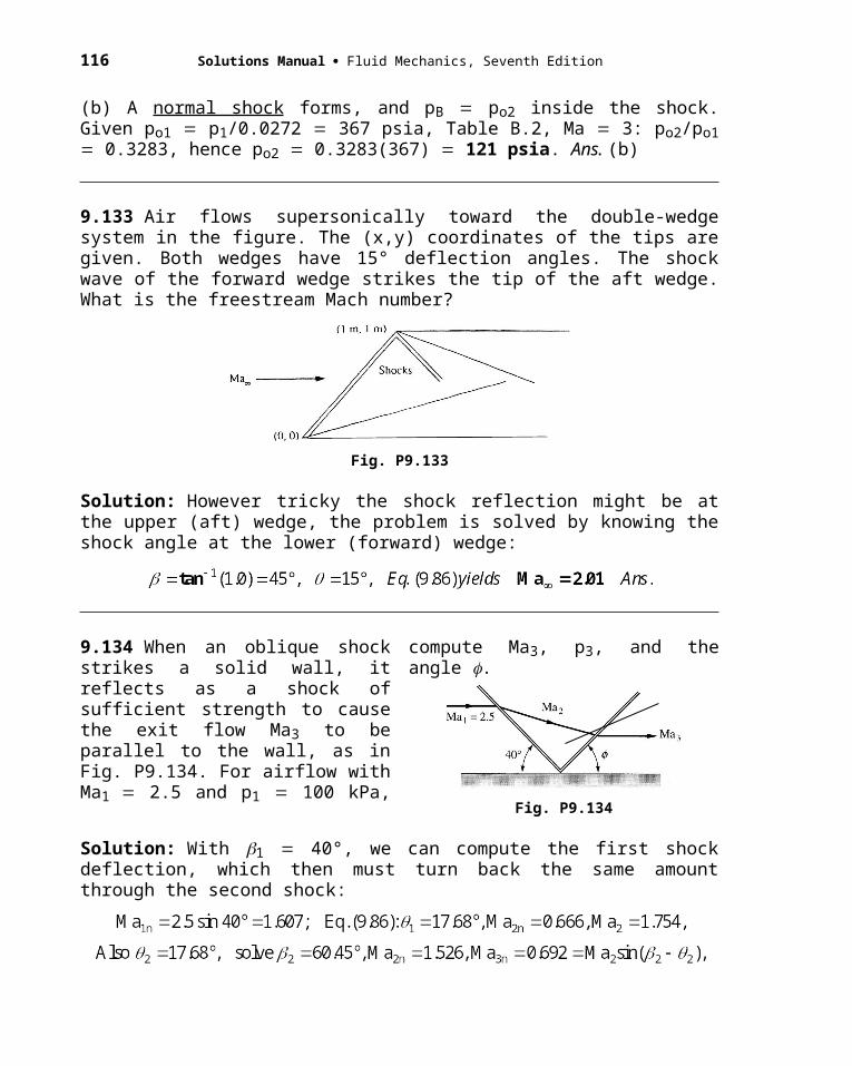
116 Solutions Manual Fluid Mechanics, Seventh Edition
For real steam, we use EES. The nice P ower-law ideal-gas formulas, Eqs. (9.26–9.28), are invalid, but the energy equation (9.22) is valid, and the nozzle flow is isentropic. First evaluate
ho ENTHALPY(steam, p 100, T 473) 2875 kJ/kgK
so ENTROPY(steam, p 100, T 473) 7.833 kJ/kgK
Then use the energy equation with the known pressure at the exit:
The specific request was for the exit temperature and the mass flow:
Te TEMPERATURE(steam, p 70, s 7.833) 434 K Ans. (a)
e DENSITY(steam, p 70, s 7.833) 0.351 kg/m3
mass flow eAeVe (0.351 kg/m3)( /4)(0.02 m)2(385 m/s) 0.0425 kg/s Ans. (a)
EES now has a speed of sound function, so we can compute
ae = SOUNDSPEED(steam, p 70, s 7.833) 512 m/s
Hence the exit Mach number is Mae = (385 m/s)/(512 m/s) = 0.75The agreement with perfect-gas theory is excellent.
(b) We are asked to determine pe for which the flow is choked, using EES. Ideal gas theory for k 1.33 predicts from Eq. (9.32) that p*/po 0.54. For EES, real steam, we use the same procedure as in part (a) above and reduce pexit gradually until the mass flow is a maximum. The final result is pe = 54.2 kPa:
C9.6 Extend Prob. C9.5 as follows. Let the nozzle be converging-diverging, with an exit diameter of 3 cm. Assume isentropic flow. (a) Find the exit Mach number, pressure, and temperature for an ideal gas, from Table A.4. Does the mass flow agree with the value of 0.0452 kg/s in Prob. C9.5? (b) Investigate, briefly, the use of EES for this problem and explain why part (a) is unrealistic and poor convergence of EES is obtained.
[HINT: Study the pressure and temperature state predicted by part (a).]
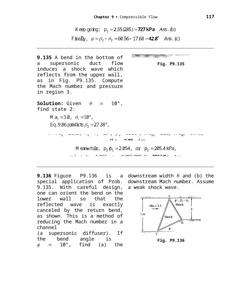
Chapter 9 Compressible Flow 117
Solution: (a) For steam as an ideal gas, from Table A.4, k 1.33 and R 461 J/kgK.
For the exit pressure, temperature, and mass flow, use the ideal Power-law relations:
The mass flow does equal the choked-flow value from Prob. C9.5, as expected.
(b) Recall from Prob. C9.5 that po 100 kPa and To 200C, which corresponds for real steam (EES) to ho 2875 kJ/kgK and so 7.833 kJ/kg. We proceed through the nozzle, using the energy equation, ho h V2/2, plus the condition of constant entropy. We also know that the flow is choked at 0.0452 kg/s with a throat diameter of 2 cm. The results are, for real steam,
Mae 2.22; pe 10.2 kPa; Te 319 K; e 0.0725 kg/m3; Quality 96%
The ideal-gas theory is still reasonably accurate at this point, but it is unrealistic, since the real steam has entered the two-phase (wet) region.
C9.7 Professor Gordon Holloway and his student, Jason Bettle, of the University of New Brunswick, obtained the following tabulated data for blow-down air flow through a converging-diverging nozzle similar in shape to Fig. P3.22. The supply tank pressure and temperature were 29 psig and 74 F, respectively. Atmospheric pressure was 14.7 psia. Wall pressures and centerline stagnation pressures were measured in the expansion section, which was a frustrum of a cone. The nozzle throat is at x 0.
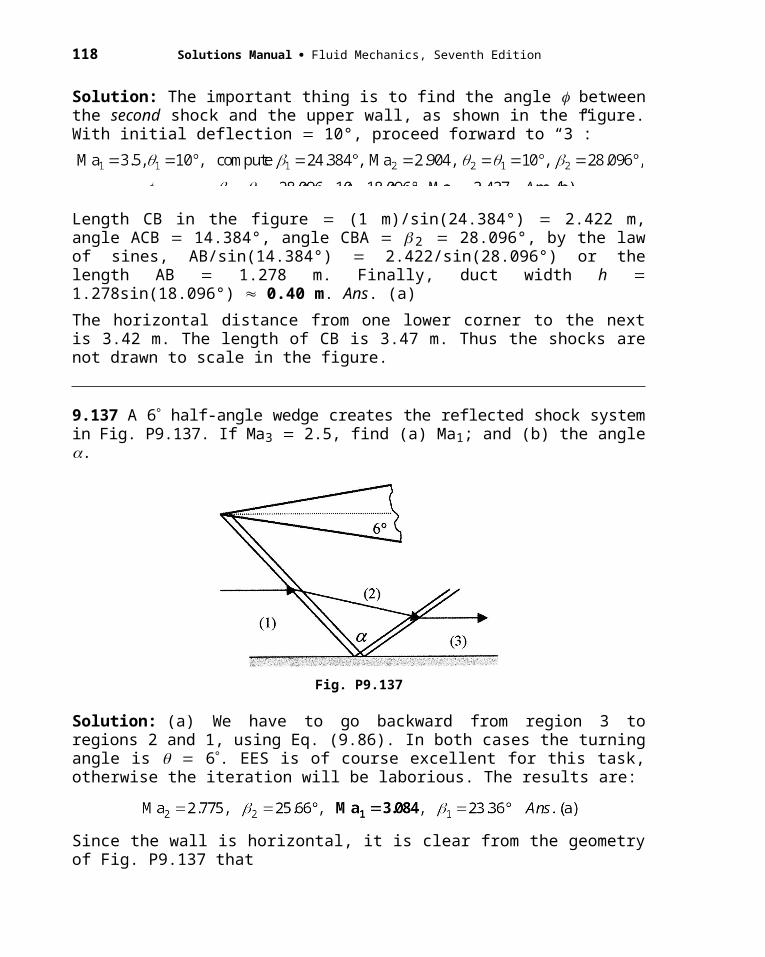
118 Solutions Manual Fluid Mechanics, Seventh Edition
x (cm): 0 1.5 3 4.5 6 7.5 9
Diameter (cm): 1.00 1.098 1.195 1.293 1.390 1.488 1.585
pwall (psig): 7.7 –2.6 –4.9 –7.3 –6.5 –10.4 –7.4
pstagnation (psig):
29 26.5 22.5 18 16.5 14 10
Use the stagnation pressure data to estimate the local Mach number. Compare the measured Mach numbers and wall pressures with the predictions of one-dimensional theory. For x 9 cm, the stagnation pressure data was not thought by Holloway and Bettle to be a valid measure of Mach number. What is the probable reason?
Solution: From the cone’s diameters we can determine A/A* and compute theoretical Mach numbers and pressures from Table B.1. From the measured stagnation pressures we can compute measured (supersonic) Mach numbers, because a normal shock forms in front of the probe. The ratio po2/po1 from Eq. (9.58) or Table B.2 is used to estimate the Mach number.
x (cm): 0 1.5 3 4.5 6 7.5 9
Ma-theory: 1.00 1.54 1.79 1.99 2.16 2.31 2.45
pw-theory (psia): 23.1 11.2 7.72 5.68 4.36 3.44 2.77
The comparison of measured and theoretical Mach number is shown in the graph below.
Problem C9.7
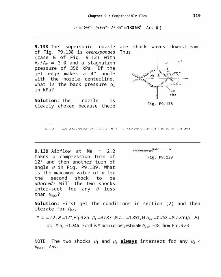
Chapter 9 Compressible Flow 119
The comparison of measured and theoretical static pressure is shown in the graph below.
Holloway and Bettle discounted the data for x 9 cm, which gave Mach numbers and pressures widely divergent from theory. It is probably that a normal shock formed in the duct.
C9.8 Engineers call the supersonic combustion, in the scramjet of Fig. 9.30, almost miraculous, “like lighting a match in a hurricane”. Figure C9.8 is a crude idealization of the engine. Air enters, burns fuel in the narrow section, then exits, all at supersonic speeds. There are no shock waves. Assume areas of 1 m2 at sections 1 and 4 and 0.2 m2 at sections 2 and 3. Let the entrance conditions be Ma1 = 6, at 10,000 m standard altitude. Assume isentropic flow from 1 to 2, frictionless heat transfer from 2 to 3 with Q = 500 kJ/kg, and isentropic flow from 3 to 4. Calculate the exit conditions and the thrust produced.
Combustion
Ma > 1 Ma > 1
1
2 3
4Fig. C9.8
120 Solutions Manual Fluid Mechanics, Seventh Edition
Solution: From Table B.6 at 10,000 m, p1 = 26416 Pa, T1 = 223.16 K, 1 = 0.4125 kg/m3, and a1 = 299.5 m/s. Calculate the inlet velocity and mass flow:
Now find conditions at section 2, assuming one-dimensional isentropic steady flow:
Use frictionless heat-addition theory to get from section 2 to section 3:
Now move isentropically from section 3 to section 4 (staying supersonic, of course):
Chapter 9 Compressible Flow 121
Check the mass flow = (1883)(1.0)(0.394) =741 kg/s, Yes. For a control volume around the scramjet, we find that the thrust is due to both velocity changes and pressure changes:
Excellent force, but the combustion chamber has to withstand high pressures (8 atm) and high temperatures (2600 K). For this simple one-dimensional model, the thrust goes up linearly with Q.


![Elements of Soil Mechanics, 7th Edition --[G._N._Smith_G.N._Smith]__7th ed. - 2009.pdf](https://img.pdfslide.net/doc/110x75/577c781d1a28abe0548ec9ad/elements-of-soil-mechanics-7th-edition-gnsmithgnsmith7th-ed.jpg)