Embed Size (px)
Citation preview

8" 4-LINK SUSPENSION SYSTEMFord Super Duty 4WD | 2011-2016
Rev. 051817
Part#: 013813
491 W. Garfield Ave., Coldwater, MI 49036 . Phone: 517-279-2135E-mail: [email protected]
2 | 013813
Read And Understand All Instructions And Warnings Prior To Installation Of
System And Operation Of Vehicle.
BEFORE YOU STARTBDS Suspension Co. recommends this system be installed by a professional technician. In addition to these instructions, professional knowledge of disassembly/ reassembly procedures and post installation checks must be known.
FOR YOUR SAFETYCertain BDS Suspension products are intended to improve off-road performance. Modifying your vehicle for off-road use may result in the vehicle handling differently than a factory equipped vehicle. Extreme care must be used to prevent loss of control or vehicle rollover. Failure to drive your modified vehicle safely may result in serious injury or death. BDS Suspension Co. does not recommend the combined use of suspension lifts, body lifts, or other lifting devices. You should never operate your modified vehicle under the influence of alcohol or drugs. Always drive your modified vehicle at reduced speeds to ensure your ability to control your vehicle under all driving conditions. Always wear your seat belt.
BEFORE INSTALLATION• Special literature required: OE Service Manual for model/year of vehicle.
Refer to manual for proper disassembly/reassembly procedures of OE and related components.
• Adhere to recommendations when replacement fasteners, retainers and keepers are called out in the OE manual.
• Larger rim and tire combinations may increase leverage on suspension, steering, and related components. When selecting combinations larger than OE, consider the additional stress you could be inducing on the OE and related components.
• Post suspension system vehicles may experience drive line vibrations. Angles may require tuning, slider on shaft may require replacement, shafts may need to be lengthened or trued, and U-joints may need to be replaced.
• Secure and properly block vehicle prior to installation of BDS Suspension components. Always wear safety glasses when using power tools.
• If installation is to be performed without a hoist, BDS Suspension Co. recommends rear alterations first.
• Due to payload options and initial ride height variances, the amount of lift is a base figure. Final ride height dimensions may vary in accordance to original vehicle attitude. Always measure the attitude prior to beginning installation.
Your truck is about to be fitted with the best suspension system on the market today. That means you will be driving the baddest looking truck in the neighborhood, and you’ll have the warranty to ensure that it stays that way for years to come.
Thank you for choosing BDS Suspension!
38x13.50 w/ 18x9 w/ 4-1/2" Backspacing
BEFORE YOU DRIVECheck all fasteners for proper torque. Check to ensure for adequate clearance between all rotating, mobile, fixed, and heated members. Verify clearance between exhaust and brake lines, fuel lines, fuel tank, floor boards and wiring harness. Check steering gear for clearance. Test and inspect brake system.
Perform steering sweep to ensure front brake hoses have adequate slack and do not contact any rotating, mobile or heated members. Inspect rear brake hoses at full extension for adequate slack. Failure to perform hose check/ replacement may result in component failure. Longer replacement hoses, if needed can be purchased from a local parts supplier.
Perform head light check and adjustment.
Re-torque all fasteners after 500 miles. Always inspect fasteners and components during routine servicing.

013813 | 3
Box Kit
Part # Qty Description
22528D 1 Front Brake Line (drv)
22528P 1 Front Brake Line (pass)
22527 2 Rear Brake Line
5188 6 Brake Line Clip
CCW-03-050 4 3/8" Crush Washer
02431 1 Brake Line Brkt (drv)
02432 1 Brake Line Brkt (pass)
083404R 1 Pitman Arm
01555 1 Stabilizer Bracket
YJTC5 1 Stabilizer Spacer
657 1 Bolt Pack - Stabilizer2 1/2"-13 x 1-1/4" bolt
2 1/2"-13 prevailing torque nut
6 1/2" SAE flat washer
1 12mm-1.75 x 80mm bolt
1 12mm-1.75 prevailing torque nut
02030B 2 Bump Stop Bracket
435 1 Bolt Pack4 5/16"-18 x 1-1/4" bolt
4 5/16"-18 prevailing torque nut
8 5/16" SAE washer
2 1/4"-20 x 3/4" bolt
2 1/4"-20 prevailing torque nut
4 1/4" SAE flat washer
2 Clamp
422 1 Bolt Pack4 3/8"-16 x 1-1/4" bolt
4 3/8"-16 prevailing torque nut
8 3/8" USS flat washer
01044B 1 Sway Bar Drop Bracket
01045B 1 Sway Bar Drop Bracket
02034B 1 Track Bar Bracket
Box Kit
02019 2 Cam Washer
02026B 1 4-Link Bracket
02027B 1 4-Link Bracket
3527BK 8 Bushing
60107 4 90° grease zerk
432 1 Bolt Pack14 1/2"-13 x 1-1/2" bolt
1 1/2"-13 x 1" bolt
14 1/2"-13 prevailing torque nut
28 1/2" SAE flat washer
4 3/4"-10 x 5-1/2" bolt
4 3/4"-10 preveiling torque nut
8 3/4" SAE flat washer
2 Wire Clip
2 1/4"-20 x 3/4" bolt
2 1/4"-20 prevailing torque nut
4 1/4" SAE flat washer
7 4 1.000 x 0.120 x 3.250 Sleeve
02007B 2 Upper Control Arm
02008B 2 Lower Control Arm
01046 1 Fuel Module Spacer
01975 1 1" Block
01048 1 Hanger Bracket
436 1 Bolt Pack1 8mm-1.25 x 75mm bolt
1 5/16"-18 x 1-1/4" bolt
3 5/16"-18 prevailing torque nut
7 5/16" USS flat washer
2 5/16"-18 x 2" bolt
02415 2 U-Bolt Plate
583581200R 4 5/8" x 3-5/8" x 12" Round U-bolt
N58FH 8 5/8" High Nut
W96USS 8 9/16" USS Flat Washer
4 | 013813
INSTALLATION INSTRUCTIONS
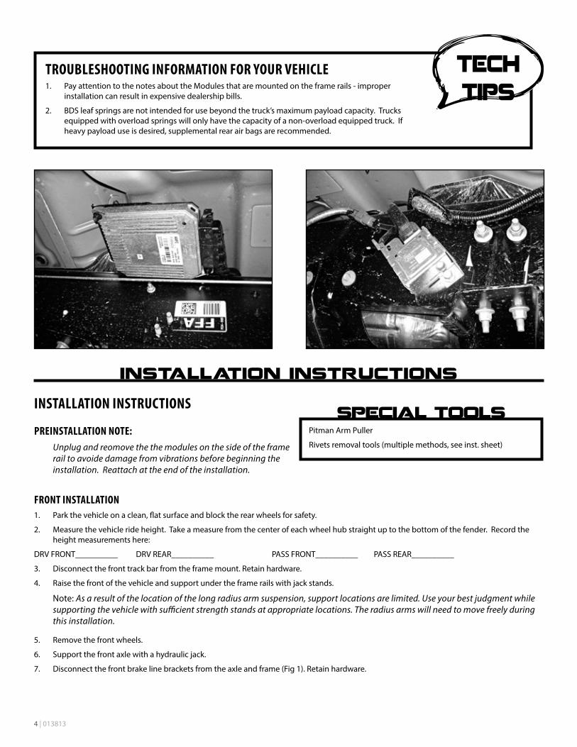
PREINSTALLATION NOTE:Unplug and reomove the the modules on the side of the frame rail to avoide damage from vibrations before beginning the installation. Reattach at the end of the installation.
FRONT INSTALLATION1. Park the vehicle on a clean, flat surface and block the rear wheels for safety.
2. Measure the vehicle ride height. Take a measure from the center of each wheel hub straight up to the bottom of the fender. Record the height measurements here:
DRV FRONT__________ DRV REAR__________ PASS FRONT__________ PASS REAR__________
3. Disconnect the front track bar from the frame mount. Retain hardware.
4. Raise the front of the vehicle and support under the frame rails with jack stands.
Note: As a result of the location of the long radius arm suspension, support locations are limited. Use your best judgment while supporting the vehicle with sufficient strength stands at appropriate locations. The radius arms will need to move freely during this installation.
5. Remove the front wheels.
6. Support the front axle with a hydraulic jack.
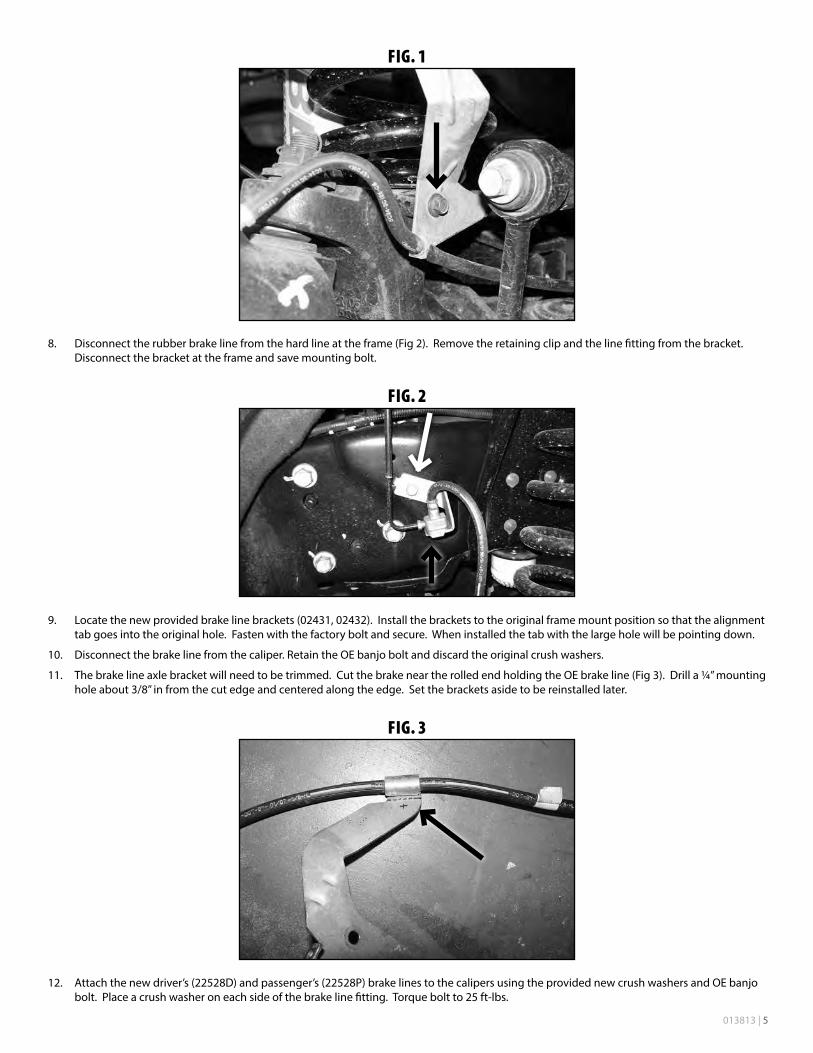
7. Disconnect the front brake line brackets from the axle and frame (Fig 1). Retain hardware.
Pitman Arm Puller
Rivets removal tools (multiple methods, see inst. sheet)
TROUBLESHOOTING INFORMATION FOR YOUR VEHICLE1. Pay attention to the notes about the Modules that are mounted on the frame rails - improper
installation can result in expensive dealership bills.
2. BDS leaf springs are not intended for use beyond the truck’s maximum payload capacity. Trucks equipped with overload springs will only have the capacity of a non-overload equipped truck. If heavy payload use is desired, supplemental rear air bags are recommended.
013813 | 5
FIG. 1
8. Disconnect the rubber brake line from the hard line at the frame (Fig 2). Remove the retaining clip and the line fitting from the bracket. Disconnect the bracket at the frame and save mounting bolt.
FIG. 2
9. Locate the new provided brake line brackets (02431, 02432). Install the brackets to the original frame mount position so that the alignment tab goes into the original hole. Fasten with the factory bolt and secure. When installed the tab with the large hole will be pointing down.
10. Disconnect the brake line from the caliper. Retain the OE banjo bolt and discard the original crush washers.
11. The brake line axle bracket will need to be trimmed. Cut the brake near the rolled end holding the OE brake line (Fig 3). Drill a ¼” mounting hole about 3/8” in from the cut edge and centered along the edge. Set the brackets aside to be reinstalled later.
FIG. 3
12. Attach the new driver’s (22528D) and passenger’s (22528P) brake lines to the calipers using the provided new crush washers and OE banjo bolt. Place a crush washer on each side of the brake line fitting. Torque bolt to 25 ft-lbs.

6 | 013813
13. Run the opposite end of the new brake lines up through the new frame brackets and attach to the OE hard line. Tighten fitting securely. Attach the lines to the new brackets with the provided clips (5188).
14. Free the hub vacuum lines from the axle (Fig 4A, 4B).
FIG. 4A
FIG. 4B
15. Disconnect the sway bar end links from the sway bar. Retain hardware.
16. Remove the OE shock. Retain lower mounting hardware.
17. Remove the ABS line from the retaining tab on the radius arm (Fig 5). Carefully pull the plastic retaining clip free from the radius arm (Fig 6).
FIG. 5
FIG. 6
18. Disconnect the OE steering stabilizer from the mount on the passenger's frame rail. Remove the factory frame mount, it will not be reused.
19. Locate the new provided stabilizer frame bracket (01555). Mount the bracket to the top two existing holes on the backside of the passenger's side engine crossmember using the 1/2" hardware provided in bolt pack #657 (Fig 7A). Mount the stabilizer to the new bracket with the 12mm hardware and 3/4" steel spacer (YJTC5). Torque hardware to 55 ft-lbs (Fig 7B).

013813 | 7
FIG. 7A
FIG. 7B
20. Disconnect the (5) bolts mounting the OE track bar bracket to the frame. Remove bracket and retain hardware.
21. Disconnect the drag link from the pitman arm. Retain hardware. Free the drag link from the pitman arm with a pickle fork.
22. Remove the pitman arm nut. Note the indexing of the pitman arm in relation to the steering sector shaft and remove the pitman arm from the steering box using the appropriate puller.
23. Remove all of the dri-lock compound on the threads of the OE nut and steering sector shafts. This is important to ensure that the new thread lock compound will adhere properly.
24. Apply a bead of the supplied thread lock all the way around the threads of the OE nut.
25. Install the new pitman arm (indexed the same as the OE) and fasten with the OE nut. Torque the nut to 350 ft-lbs.
26. Lower the axle until the OE coil springs are free and remove the springs from the vehicle. Retain the upper spring isolator for use with the new springs.
Note: Do not over extend the brake lines.
27. Install the new track bar bracket (02034) using the stock mounting hardware as it was removed (Fig 8A, 8B). Torque all (5) mounting bolts to 129 ft-lbs.
FIG. 8A (FROM FRONT)
FIG. 8B (FROM REAR)
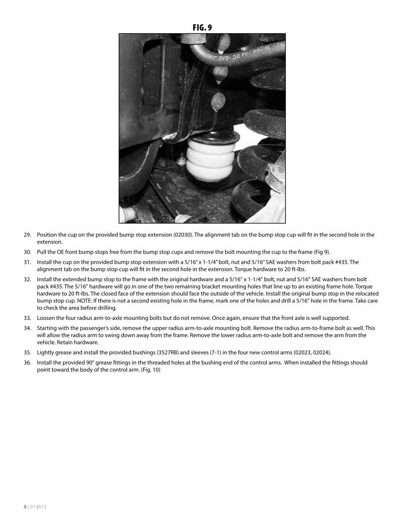
28. Pull the OE front bump stops free from the bump stop cups and remove the bolt mounting the cup to the frame (Fig 9).
8 | 013813
FIG. 9
29. Position the cup on the provided bump stop extension (02030). The alignment tab on the bump stop cup will fit in the second hole in the extension.
30. Pull the OE front bump stops free from the bump stop cups and remove the bolt mounting the cup to the frame (Fig 9).
31. Install the cup on the provided bump stop extension with a 5/16” x 1-1/4” bolt, nut and 5/16” SAE washers from bolt pack #435. The alignment tab on the bump stop cup will fit in the second hole in the extension. Torque hardware to 20 ft-lbs.
32. Install the extended bump stop to the frame with the original hardware and a 5/16" x 1-1/4" bolt, nut and 5/16" SAE washers from bolt pack #435. The 5/16" hardware will go in one of the two remaining bracket mounting holes that line up to an existing frame hole. Torque hardware to 20 ft-lbs. The closed face of the extension should face the outside of the vehicle. Install the original bump stop in the relocated bump stop cup. NOTE: If there is not a second existing hole in the frame, mark one of the holes and drill a 5/16" hole in the frame. Take care to check the area before drilling.
33. Loosen the four radius arm-to-axle mounting bolts but do not remove. Once again, ensure that the front axle is well supported.
34. Starting with the passenger’s side, remove the upper radius arm-to-axle mounting bolt. Remove the radius arm-to-frame bolt as well. This will allow the radius arm to swing down away from the frame. Remove the lower radius arm-to-axle bolt and remove the arm from the vehicle. Retain hardware.
35. Lightly grease and install the provided bushings (3527RB) and sleeves (7-1) in the four new control arms (02023, 02024).
36. Install the provided 90° grease fittings in the threaded holes at the bushing end of the control arms. When installed the fittings should point toward the body of the control arm. (Fig. 10)

013813 | 9
FIG. 10
37. Locate the seven rivets that attach the OE radius arm mounting bracket to the frame. There will be four on the outside and three in the inside of the bracket fastening the bracket to the bottom of the frame. (Fig. 11)
FIG. 11
38. Remove the seven rivets with a grinder, drill, or combination of these tools. Do not use a torch or air chisel. The undercoating used on the frame is highly flammable. Disconnect the electronic control module and fuel lines that are mounted and ran on the inside of the driver’s side frame rail, repeat process on passenger's side if modules are present. Vibrations from tools may ruin these expensive modules.
39. With the rivets removed, free the radius arm bracket from the frame. Ensure that all of the rivets are removed from the holes in the frame.
40. Place the new passenger’s side 4-Link bracket (02027) up to the frame and align the existing rivet holes with the corresponding holes in the bracket. Attach the bracket with ½” x 1-1/2” bolts, nuts and ½” SAE flat washers from bolt pack #432. Torque ½” hardware to 90 ft-lbs. (Fig. 12, 13)

10 | 013813
FIG. 12
FIG. 13
41. Install the assembled upper control arm in the new frame bracket and fasten with a ¾” x 5-1/2” bolt, nut and ¾” SAE flat washers from bolt pack #432. The two tabs on the control arm go up. Leave hardware loose. (Fig. 14)
FIG. 14
42. Attach the axle end of the control arm with the original hardware. Leave hardware loose. (Fig. 15)
FIG. 15

013813 | 11
43. Install the new lower control arm in the new frame bracket with a ¾” x 5-1/2” bolt, nut and ¾” SAE flat washers. Install arm so that the grease fitting is up. Leave hardware loose.
44. With the axle well supported, disconnect the driver’s side radius arm from the axle. Retain hardware.
45. Attach the new passenger’s side lower control arm to the axle with the original hardware. Leave hardware loose.
46. If equipped, remove the 3 nuts mounting the fuel module to the inside of the driver’s side frame rail above the radius arm bracket (Fig 16A). Remove the fuel lines from the clip just ahead of the fuel module on the inside of the frame and pull the module in, away from the frame (Fig 16B). Retain hardware.
FIG. 16A
FIG. 16B
47. Repeat the frame bracket and control arm installation procedure on the driver’s side of the vehicle. When mounting the new bracket, use a ½” x 1” bolt in the 2nd (from the front) outside mounting hole (Fig 17A). This shorter bolt is necessary to properly clear the fuel module when it is reinstalled. Note: Use the nut that was removed from the radius arm-to-frame bolt for the upper control arm-to-axle mount bolt when installing the new control arm. The OE nut in this position is welded to the radius arm.
48. Install the provided fuel module spacer plate over the 3 studs of the fuel module bracket and reinstall the module in the original holes with the factory nuts (Fig 17B). Torque nuts to 20 ft-lbs.
FIG. 17A
FIG. 17B
49. With all of the control arms attached, reinstall the fuel junction block (if removed) on the driver’s side frame rail. Torque hardware to 20 ft-lbs.
50. Attach the plastic ABS wire clip to the front tab on the new upper control arm. Secure the wire to the rear tab with the provided wire clip and 1/4" x 3/4" bolt, nut and 1/4" USS washers (BP 432). Torque 1/4" hardware to 10 ft-lbs. (Fig. 18)

12 | 013813
FIG. 18
51. Install the new coil springs in conjunction with the OE top isolator. Rotate the springs so that they seat in the bottom coil perch properly.
52. Install the new shocks using the original lower mounting hardware and the provided upper mounting hardware. Torque the lower bolt to 100 ft-lbs and the upper until the bushings begin to swell.
53. Note the orientation of the front sway bar (top verses bottom). Disconnect the sway bar from the frame and remove from the vehicle. Retain hardware.
54. Install the provided sway bar drop bracket (01044, 01045) to the original sway bar frame mounting locations with the original hardware. Mount the drop bracket with the open face toward the inside of the vehicle and the bracket offset toward the front. Torque hardware to 30 ft-lbs.
55. Attach the sway bar to the new drop brackets in the correct orientation with the 3/8” hardware from bolt pack #422. Torque hardware to 30 ft-lbs (Fig 19).
FIG. 19
56. Install the sway bar link ends to the sway bar and secure with the OE hardware. Torque to 90 ft-lbs.
57. Fasten the modified OE brake line axle brackets to the axle in their original location with the factory hardware. Torque hardware to 10 ft-lbs.
58. Attach the new brake line to the bracket with a provided clamp, ¼” x ¾” bolt, nut and washers (BP 435) using the hole drilled earlier. Torque bolt to 10 ft-lbs.
59. Properly bleed the brake system of air and top off the brake fluid reservoir with the proper type of fluid (see owners manual).
60. Check front driveshaft for binding. In some cases the u-joints may max out and require a replacement driveshaft.
61. Install the wheels and lower the vehicle to the ground.
62. Attach the track bar to the new bracket with the OE hardware. Turn the steering wheel to aid in aligning the track bar in the bracket. Install the provided cam washers (02019) between the alignment tabs on the bracket. The cam washers have an offset hole. Position the cam washer in the position that best centers the axle under the vehicle. Fasten with the OE bolt and nut. Torque hardware to 400 ft-lbs. (Fig. 20)
013813 | 13
63. Torque all six radius arm bolts to 250 ft-lbs.
FIG. 20
REAR INSTALLATION64. Raise the rear of the vehicle and support with jack stands under the frame rails just ahead of the spring hangers.
65. Remove the wheels.
66. Support the axle with a hydraulic jack.
67. Remove the OE shocks. Retain all mounting hardware.
68. Remove the ABS wires from the axle bracket near the differential.
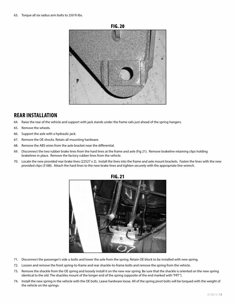
69. Disconnect the two rubber brake lines from the hard lines at the frame and axle (Fig 21). Remove brakeline retaining clips holding brakelines in place. Remove the factory rubber lines from the vehicle.
70. Locate the new provided rear brake lines (22527 x 2). Install the lines into the frame and axle mount brackets. Fasten the lines with the new provided clips (5188). Attach the hard lines to the new brake lines and tighten securely with the appropriate line wrench.
FIG. 21
71. Disconnect the passenger’s side u-bolts and lower the axle from the spring. Retain OE block to be installed with new spring.
72. Loosen and remove the front spring-to-frame and rear shackle-to-frame bolts and remove the spring from the vehicle.
73. Remove the shackle from the OE spring and loosely install it on the new rear spring. Be sure that the shackle is oriented on the new spring identical to the old. The shackles mount of the longer end of the spring (opposite of the end marked with “FRT”).
74. Install the new spring in the vehicle with the OE bolts. Leave hardware loose. All of the spring pivot bolts will be torqued with the weight of the vehicle on the springs.

14 | 013813
75. Remove all dirt and corrosion from the axle spring pad and raise the axle to the spring while aligning the center pin with the center pin hole. Fasten the spring with the provided u-bolts and new top u-bolt plate. Position the u-bolt plate so the bolt pattern is centered on the center pin.. Snug but do not torque u-bolts at this time.
76. Repeat the procedure on the driver’s side. Disconnect the parking brake cable bracket from the center pin (Fig 22). Take care not to over extend the brake lines.
FIG. 22
77. If more parking brake cable slack is needed, remove the cable from the rear-most retaining bracket on the frame. (Fig 23)
FIG. 23
78. Install the new shocks with the original mounting hardware.
79. Install wheels and lower the vehicle to the ground.
80. Attach the ABS lines to the new stainless steel brakelines with the provided zip ties.
81. With the weight of the vehicle on the axle, torque the u-bolts to 130-150 ft-lbs.
82. Bleed the entire brake system. Be sure to check brakes before moving the vehicle. See service manual for proper bleeding procedure, Use only approved brake fluid type listed in owner's manual.
83. Check all hardware for proper torque.
84. Cylcle the steering and check for proper clearance, optional bumper spacer kit is available for the front bumper to clear larger than specified tires / wheels.
85. Adjust steering wheel.
86. Adjust headlights
87. Check hardware after 500 miles.

013813 | 15
EXHAUST RELOCATION—DIESEL ONLY:88. Remove the bolts mounting the rear exhaust hanger to the frame. Retain hardware.
89. Remove the nuts mounting the exhaust hanger located just ahead of the rear axle. The nuts are accessed from above the crossmember. Remove the bracket from the crossmember and the rubber exhaust grommets.
90. Using a hammer, remove the captive studs from the front bracket (Fig A)
FIG. A
91. Reinstall the front bracket to the crossmember along with the provided 1” spacer block (01975). Fasten the OE bracket and spacer block through the original crossmember holes with 5/16” x 2” bolts, nuts and washers (BP 436). Torque bolts to 20 ft-lbs (Fig B).
FIG. B
92. Reinstall the rubber exhaust grommets on the relocated front exhaust hanger. A small amount of grease on the rubber grommet will ease installation.
93. Fasten the provided rear exhaust hanger relocation bracket to the original hole on the side of the frame with a 5/16” x 1-1/4” bolt, nut and washers (BP 436). Leave hardware loose.
94. Attach the OE rear exhaust hanger to the relocation bracket with OE bolt run from inside the relocation bracket out into the captive nut on the OE hanger. Run a provided 8mm x 75mm bolt/washer up through the bottom OE hanger mounting hole, through the relocation bracket and into the captive nut in the bottom of the frame. With all the hardware installed torque bolts to 20 ft-lbs (Fig C).

16 | 013813
FIG. C
Thank you for choosing BDS Suspension.For questions, technical support and warranty issues relating to this BDS Suspension product, please contact your distributor/installer
before contacting BDS Suspension directly.