Embed Size (px)
Citation preview

... where quality is measured.
Instruction Manual
Brabender® GmbH & Co. KG •••• Kulturstr. 51-55 •••• 47055 Duisburg •••• Germany ���� Phone - 49 - 203 - 7788 - 0 •••• ���� Fax - 49 - 203 - 7788 - 102
���� E-mail: [email protected]
Agencies all over the world Brabender GmbH & Co. KG 2009 Copyright protection DIN 34 Edition 1109 Instruction Manual No. 800150-000_Amylograph-E_BA-00-e
Amylograph-E
Ident no. 8 001 50
230 V, 50 Hz

REGISTRATION CARD Brabender® GmbH & Co. KG
Important! Please complete and return to: Important! Veuillez compléter et retourner à: / Wichtig! Bitte ausfüllen und zurücksenden an: /
Importante: Voglia completare e rispedire a: / Importante: Haga el favor de completar y devolver a:
Brabender GmbH & Co. KG, Kulturstr. 51-55, 47055 Duisburg, Germany Tel. No: ++ 49 - 203 - 7788 - 0
Fax. No.: ++ 49 - 203 - 7788 - 100 E-mail: [email protected]
Please state the Brabender order no. of your equipment: Inscrire ici le numéro de commande Brabender de votre appareil / Bitte hier die Brabender Order-Nr. Ihres Geräts eintragen /
Iscrivere qui il numero d'ordine Brabender dell'apparecchio / Inscribir aquí el número de pedido Brabender del aparato
USER OF EQUIPMENT Utilisateur / Benutzer / Utente / Utilizador
Title __________________________________ Titre / Titel / Titolo / Titulo
Surname __________________________________ Nom / Name / Cognome / Appelido
First Name __________________________________ Prénom / Vorname / Nome / Nombre
Tel. No. __________________________________ Téléphone / Telefon / Numero di telefono / Número de teléfono
Fax No. __________________________________ Télécopieur / Fax / Numero di fax / Número de fax
Company __________________________________ Société / Firma / Ragione Sociale / Nombre de la Compañía
Address __________________________________ Adresse / Adresse / Indirizzo / Dirección
__________________________________ Country __________________________________ Pays / Land / Nazione / País
E-mail __________________________________
EQUIPMENT Appareil / Gerät / Apparecchio / Aparato
Instrument / Software __________________________________________________________________ Instrument / Logiciel Apparecchio / Software __________________________________________________________________ Aparato / Software
Ident No. __________________________________
Version No. __________________________________ (only in case of software / seulement pour logiciel / nur für Software / solamente per il software / solamente para el software)
� If you do not wish your name to be used for marketi ng purposes, tick this box. Si vous ne souhaitez pas que votre nom soit utilisé a des fins commerciales, cochez cette case. / Wenn Sie nicht wünschen, dass Ihr
Name für Marketingzwecke verwendet wird, kreuzen Sie dieses Feld an. / Spunti questa casella se non desidera che il Suo nome venga utilizzato a scopi di marketing. / Marque el recuadro si no desea que su nombre sea usado para razones comerciales.

Amylograph-E 3
Contents
1 GENERAL INFORMATION................................ .....................................5
1.1 Symbols and abbreviations ............................................................................................................5
1.2 Application......................................................................................................................................6
1.3 Disclaimer of liability.......................................................................................................................6
1.4 Noise measurement .......................................................................................................................6
2 SAFETY ..................................................................................................7
2.1 Due application ..............................................................................................................................7
2.2 Safety instructions for the user.......................................................................................................7
3 TRANSPORT AND STORAGE.............................. .................................8
3.1 Packing...........................................................................................................................................8
3.2 Transport ........................................................................................................................................8
3.3 Unpacking ......................................................................................................................................8
3.4 Scope of supply..............................................................................................................................8
3.5 Notification of damage ...................................................................................................................8
3.6 Storage...........................................................................................................................................8
4 FEATURES AND OPERATING PRINCIPLE................... ........................9
4.1 Basic instrument.............................................................................................................................9 4.1.1 Measuring bowl and measuring sensor ............................................................................10 4.1.2 Heating..............................................................................................................................11 4.1.3 Temperature controller......................................................................................................11 4.1.4 Communication ports ........................................................................................................12 4.1.5 Mains connection ..............................................................................................................12
4.2 Additional equipment for Rapid Amylogram.................................................................................12
4.3 Computer* with monitor*, printer*, and software..........................................................................13 4.3.1 Computer* and monitor* ...................................................................................................13 4.3.2 Printer* ..............................................................................................................................13 4.3.3 Software............................................................................................................................13
5 TECHNICAL DATA..................................... ..........................................15
6 INSTALLATION ....................................... .............................................16
6.1 Basic requirements ......................................................................................................................16
6.2 Setup and assembly.....................................................................................................................16 6.2.1 Mounting the instrument ...................................................................................................16 6.2.2 Mains connection ..............................................................................................................17 6.2.3 PC connection...................................................................................................................17
6.2.3.1 Wiring..................................................................................................................17 6.2.3.2 Installation of the USB drivers ............................................................................18
6.2.4 Software presettings .........................................................................................................18 6.2.4.1 Language............................................................................................................18 6.2.4.2 Definition of the instrument and ports.................................................................19
4 Amylograph-E
7 START-UP AND OPERATION............................. .................................21
7.1 Manpower requirements ..............................................................................................................21
7.2 Preparations prior to test start......................................................................................................21 7.2.1 Cleaning the measuring bowl and the measuring sensor.................................................22 7.2.2 Mounting the bowl and the measuring sensor..................................................................22 7.2.3 Switching on the instruments............................................................................................22
7.3 Test procedure .............................................................................................................................23 7.3.1 Determining the moisture content of the sample ..............................................................23 7.3.2 Entry of test parameters....................................................................................................23 7.3.3 Preparation of the buret ....................................................................................................24 7.3.4 Preparation of the suspension ..........................................................................................25
7.3.4.1 Sample preparation for a wheat flour gelatinization curve .................................25 7.3.4.2 Sample preparation for a rye flour gelatinization curve......................................26 7.3.4.3 Sample preparation for a wheat wholemeal gelatinization curve.......................27 7.3.4.4 Sample preparation for a rye wholemeal gelatinization curve ...........................28 7.3.4.5 Summary of procedures for wheat/rye flour and wheat/rye meal ......................28
7.3.5 Starting the test.................................................................................................................29 7.3.6 Displays during the test.....................................................................................................30 7.3.7 Test time, end of test ........................................................................................................30
7.4 Test evaluation .............................................................................................................................31 7.4.1 Amylogram........................................................................................................................31 7.4.2 Bread rye quality ...............................................................................................................31
7.5 Cleaning the instrument ...............................................................................................................32
8 MAINTENANCE........................................ ............................................33
8.1 Cleaning the bowl and the sensor................................................................................................33
8.2 Calibration ....................................................................................................................................33
9 TROUBLE-SHOOTING................................... ......................................34
10 ACCESSORIES ....................................................................................35
11 SPARE PARTS........................................ .............................................35
12 ANNEX..................................................................................................35

Amylograph-E 5
1 GENERAL INFORMATION
Brabender® instruments/software are of a high technical standard and comply with the demand for simple and safe handling. At the same time, they are designed for universal application and, thus, for handling manifold technical tasks. It is strongly recommended to study this instruction manual very carefully before putting the instrument into operation in order to become familiar with the manifold possible applications and to use the instrument/software in an optimum way.
This instruction manual has been supplied together with the instrument/software and is intended for operation in practice. It is to make the user familiar with the instrument/software and to inform him about functional details and maintenance.
Safety instructions and precautions have to be obse rved in order to avoid accidents due to improper handling and operation.
The information contained in this instruction manual will also be useful for the detection and repair of any possible troubles. This instruction manual is, thus, to be considered part of the instrument/software and must be available to the operating personnel.
Within the scope of legal regulations, Brabender® refuses any liability for direct or indirect damage caused in connection with the delivery or use of Brabender® instruments. This is especially true for improper use of Brabender® instruments.
Maintenance and service instructions have to be observed for reasons of safe operation and durability.
For safety reasons beware of unauthorized operatio n, any modification of Brabender instruments or any other unauthorized interference.
At the same time, it should be considered that war ranty will expire as a consequence of improper use and unauthorized operation and/or modi fication and/or any other unauthorized interference.
If there are any inquiries to Brabender® - e.g. relating to handling of instruments/software, ordering of spare parts, accessories, additional equipment or to sending back instrument parts for maintenance or repair - please always state completely all data and complete numbers given on the name plate.
For questions concerning the software, please also state the number of your software version in addition to the software ident no.
Brabender will, of course, always be at your disposal for any information going beyond the scope of this instruction manual.
1.1 Symbols and abbreviations
Some of the elements of the instrument system mentioned in this instruction manual are optional or additional equipment. They are marked with a * within the text.

6 Amylograph-E
1.2 Application
The Brabender Amylograph-E is the standard instrument for measuring the gelatinization properties of wheat and rye flour and meal, for checking the enzyme activity, for recognizing sprout damage, and for purposeful dosing of enzymes, e.g. by adding malt flour.
The test data are recorded on a PC and evaluated automatically in compliance with international standards (ICC, AACC, ISO, etc). In contrast to other instruments which just supply a single number as a result, the Amylograph-E supplies a complete curve showing all relevant information at a glance.
1.3 Disclaimer of liability
Within the scope of legal regulations, Brabender® GmbH & Co. KG refuses any liability - for whatever legal argument - for direct or indirect damage caused in connection with the delivery or use of the Brabender® instrument/software. This is in particular true for - but not limited to - improper use and/or improper operation and handling of the Brabender® instrument/software.
Under no circumstances, Brabender® GmbH & Co. KG can be made liable for any damage or injuries caused by non-observance of the safety regulations included in the data sheets of the producer of substances, e.g. polymer(s), to be tested or processed with the Brabender® instrument. This is also valid if a recommendation was made concerning the application of certain substances and/or if the provision of test material (polymers) is part of the scope of supply and service.
1.4 Noise measurement
Noise measurement was made under normal operating conditions within the speed range of the instrument at a distance of approximately 1 m and at a height of approximately 1.6 m.
The equivalent continuous sound pressure level measured is Leq < 70 dB(A) .

Amylograph-E 7
2 SAFETY
2.1 Due application
The instrument may only be used for the afore-mentioned tests with suitable materials. The instrument may only be used when completely assembled.
2.2 Safety instructions for the user
Prior to operation, the user must make sure of the correct condition and setup/assembly of the instrument. The instrument may be operated by skilled personnel only. Instructions for installation, setup, and operation must be observed.
Disregard of the safety instructions may cause dan ger for the operating personnel. This is also true for arbitrary, unauthorized, and improper modifications to the instrument.
When testing and processing materials with Brabender test instruments, the data sheets of the respective material producer concerning safety regulations must be considered by all means.
It is within the responsibility of the user's employer to set up the measures to be taken for averting any hazards that may arise when dangerous substances are handled.
Under no circumstances, Brabender can be made liable for any damage or injuries cause d be non-observance of such safety regulations.
The heating/cooling jacket may get hot - attention , danger of burning!

8 Amylograph-E
3 TRANSPORT AND STORAGE
3.1 Packing
The instruments are thoroughly packed into wooden crates. Small parts and accessories are packed into cardboard boxes or bags in the crates. Additional equipment is packed either in the same crate as the instrument or in a separate crate, depending on the scope of the order.
3.2 Transport
On the outside of the crate, there are signboards which always must be observed by all means:
This side up!
Fragile, handle with care!
Keep dry!
3.3 Unpacking
First remove the cover of the crate, then take off the lateral walls. Take care of braces and supports within the crate as well as of bolt connections to the bottom of the crate, etc.
When unpacking the equipment, take care that no small parts or accessories which are not fixed to the instrument remain in the packing material. Parts of the equipment may have loosened during transport and may be hidden between the packing material. Therefore, the whole packing material has to be searched very carefully before disposal.
Instructions on labels and stickers need to be obs erved carefully.
Covering hoods and films should not be removed until setup and commissioning, respectively.
3.4 Scope of supply
The scope of supply must be compared with the shipping documents immediately after arrival at the place of destination. If there is any discrepancy, Brabender® must be notified immediately.
3.5 Notification of damage
Inspect the instrument immediately after unpacking for any signs of damage. Should any damage be evident, regardless of whether it apparently occurred during carriage or not, notify the delivering carrier immediately and claim damages with him. If necessary, the delivering carrier must be given the opportunity to inspect the shipment. Brabender also must be notified immediately.
If, in the order, the risks of carriage were agreed to be taken by the buyer or by the receiver, the buyer or the receiver has to observe the regulations of the insurance policy.
3.6 Storage
The instrument must be stored in dry rooms only.
The admissible limit values of ambient temperature and humidity for storage and for operation are included in the list of technical data.

Amylograph-E 9
4 FEATURES AND OPERATING PRINCIPLE
The Amylograph-E is a compact instrument which mainly comprises the following components:
• basic instrument Amylograph-E
• computer* with printer*, monitor*, and software
4.1 Basic instrument
Figs. 1 and 2 show the front and rear walls of the basic instrument with the corresponding control elements and connections:
Bubble level
Fixing knob for measuring head Measuring head Measuring sensor with pins Measuring bowl Cover hood with heating Temperature controller Main power switch 4 adjustable feet
Fig. 1: Basic instrument Amylograph-E, front view
Socket for mains cable
Fuses
Ground terminal for fixing a ground cable
USB port
Fig. 2: Basic instrument Amylograph-E, rear view

10 Amylograph-E
4.1.1 Measuring bowl and measuring sensor The measuring bowl is driven at a fixed speed (75 min-1) and is heated electrically.
The measuring head to which the measuring sensor and a Pt-100 sensor (RTD) are attached, runs in a guiding rail equipped with a pneumatic spring. This pneumatic spring holds the measuring head in its upper position and permits to push it down by hand into operating position where it can be locked.
The suspension made of the flour or meal specimen and distillied water is filled into the measuring bowl. A measuring sensor reaching into the sample is deflected more or less against a load-sensing system by the sample material rotating with the bowl, depending on the viscosity of the sample. The viscosity can, thus, be measured continuously as torque.
The instrument is equipped with a high-resolution digital measuring system for torque recording. The data are displayed on the monitor in a numerical and graphical form. The nominal and actual temperatures are shown at the temperature controller.
Locking Measuring head in operating position
Fig. 3: Measuring head in operating position

Amylograph-E 11
4.1.2 Heating The measuring bowl is heated through an electric heating. The temperature in the measuring bowl is measured continuously and controlled, if required, by an RTD also immerging directly into the sample.
Measuring sensor with pins
Pt-100 sensor (RTD)
Fig. 4: Measuring system of the Amylograph-E
4.1.3 Temperature controller During the measurement, the sample temperature is controlled by the temperature controller at the front side of the instrument.
This key must not be in "Hold" position but must be set to "Auto"..
Fig. 5: Temperature controller
The temperature controller is triggered from the PC via USB. The start temperature and heating rate are entered at the computer and transmitted by the software to the temperature controller which is responsible for uniform heating of the sample.
Do not change any values at the temperature program controller! Entry of the program parameters is done only through the Amylograph software!
Nominal (lower display) and actual temperatures (upper display) can be read continuously at the temperature program controller.
The left, round key at the temperature program controller must not be set to "Hold" but must be in "Auto" position (see fig. 5).

12 Amylograph-E
4.1.4 Communication ports The Amylograph-E is equipped with a USB port.
Please also refer to the separate instruction manual for the Amylograph Windows software. The allocation of the communication ports is defined in the software program.
4.1.5 Mains connection The Amylograph-E is connected to a mains voltage of 230 V/50 Hz.
4.2 Additional equipment for Rapid Amylogram
An easily interchangeable additional equipment - a different measuring bowl and another measuring sensor - permits to considerably reduce the time required for the standard method and to measure the gelatinization properties of a flour within only 5 - 10 min.
Fig. 6: Additional equipment for the Rapid Amylogram

Amylograph-E 13
4.3 Computer* with monitor*, printer*, and software
4.3.1 Computer* and monitor* The torque signal measured during the Amylograph test is digitized by the integrated electronics and transmitted to the PC via USB. It is only after processing by the supplied software on a connected computer that the measuring result is available as an evaluated diagram.
For connection to a Amylograph-E, the computer mus t have a USB port which must be supported by the operating system!
Many commercial computers* can be applied provided that they meet certain minimum requirements:
• Computer*: IBM or compatible PC (≥ Pentium II 350 MHz, operating system Windows 98, 98 SE,
2000, XP) Hard disk: > 540 MByte Memory: ≥ 64 MByte RAM Graphic: Super VGA 800 x 600
• Monitor*: 15", 17" for Windows
4.3.2 Printer* Any modern color printer (9 or 24 needles, ink jet, laser) can be used provided it is adequate to operation under Windows.
Black and white printers can also be used, although reading a color diagram is, of course, much more comfortable.
4.3.3 Software
For proper operation of the software, it is impera tive to install the USB drivers included on the CD-ROM with the Amylograph software on the hard disk !
The following software programs are available for tests with the Amylograph-E:
1. Amylograph program for Windows (ident no. 72200, included in the scope of supply): The program evaluates and documents the tests with the Amylograph-E. The measuring values (temperature profile and torque) are recorded by the software and displayed on-line on the monitor.
Apart from that, this software allows to enter the desired start temperature and heating rate and permits to start the test.
2. Amylograph correlation program for Windows (iden t no. 72202, not included in the scope of supply): With this program, you can compare measurements run with the Amylograph program with each other. The results of up to 15 tests can be represented simultaneously in a tabular or graphical form for being compared. Mean values and standard deviations are calculated automatically by the program.

14 Amylograph-E
After processing by the software (Amylograph program for Windows ident no. 72200) on a connected computer, the results can be represented in the form of a diagram (Amylogram).
The 32-bit software records the measuring data, represents the corresponding diagram (Amylogram) on-line, and evaluates them in compliance with the most recent standards.
The 32-bit software implies a Windows 98, 2000 or XP operating system.
For connection to an Amylograph-E, the computer must be equipped with a USB port . As a consequence, the program does not run under W indows NT at present.
If a computer is included in the scope of supply, the programs are factory-installed on hard disk. If a computer is provided by the customer, the programs first need to be installed on hard disk.
The evaluated Amylogram with evaluation results, sample data, and test parameters is represented on the monitor and can be saved and printed.
The present instruction manual does not substitute the instruction manual supplied with the Amylograph Windows program but complements it.
Before working with the Amylograph-E, make yoursel f familiar both with the software and with the operation of the instrument.

Amylograph-E 15
5 TECHNICAL DATA
Sample volume: approx. 550 ml
Heating power: 500 W
Heating rate: standard (ICC): 1.5°C/min, selectable between 0.1 ... 9.9°C/min
Speed: 75 min-1
Torque measurement: electronically
PC port: USB
Mains connection: 230 V, 50 Hz
Dimensions (W * H *T): 470 * 830 * 350 mm
Weight: approx. 30 kg net
Environmental conditions: Storage: Temperature -25°C...+55°C Humidity 5...95 % rel. hum., non condensing
Operation: Temperature + 5°C...+45°C Humidity 5...95 % rel. hum., non condensing

16 Amylograph-E
6 INSTALLATION
6.1 Basic requirements
The intended base for the installation of the instrument has to be clean and plane and strong enough to carry the instrument system.
The unpacked instrument is recommended to be carried very carefully to the place of installation. Hard touch-downs must be avoided absolutely.
In case lifting tools are used, they must be fixed as near as possible to the center of gravity of the instrument and care must be taken not to damage any sensitive parts like control buttons, sockets, etc. by straps and cables.
The connection and adaptation points for the power supply of the instrument are recommended to be located as near as possible to the place of installation of the instrument.
Requirements:
Electric energy: 230 V, 50 Hz
In the annex, please find a list of the special tools supplied with the instrument. Apart from these, normal tools like screw-drivers, etc. are required.
Assembly is recommended only to be effected carefully by competent technical staff.
Electric work is only allowed to be executed by co mpetent electricians.
6.2 Setup and assembly
Cover hoods and foils should only be removed at th e final place of installation, when all remaining packaging has been removed. Information o n labels and stickers are to be noticed exactly.
6.2.1 Mounting the instrument
Place the instrument on a stable, vibration-free table.
Level the instrument exactly horizontally by means of the adjustable foot screwsand the integrated bubble level on the left side of the guide rail.
1
2
3
4
1
2

Amylograph-E 17
6.2.2 Mains connection
Mains cable socket
Ground terminal for fixing a ground cable
USB port
Fig. 7: Sockets for mains cable and PC
Switch off the instrument before connecting it to the mains!
Before connecting the instrument to the mains or t o any other power source, make sure that the power meets the data given on the nam e plate.
Connect the mains plug of the instrument to the mains.
On the rear side of the instrument, there is an additional free ground terminal for additionally grounding the instrument at a suitable earth circuit. Thus, the instrument is protected twice.
6.2.3 PC connection 6.2.3.1 Wiring As a large variety of computers is suited for operating the instrument, only some general remarks for installing the computer* and printer* are given in the following.
Place the PC and additional equipment on the table beside the instrument.
The only connection between the Amylograph-E and the PC is the USB port. Connect the USB cable to the USB port on the rear side of the instrument (fig. 7) and to the USB port of the PC.
Connect the monitor* and printer* to the PC*.
Please also observe the separate instruction manual of your PC and printer. If you have any questions concerning the operation of your PC, please contact the manufacturer or supplier of your PC.
1
2
1
2
3

18 Amylograph-E
6.2.3.2 Installation of the USB drivers
Software installation
1. Install the Amylograph software as described in the separate instruction manual for the software.
Installation of the USB drivers
1. The USB drivers are included on the CD-ROM with the Amylograph software in the following directory:
USB-Driver\Edgeport\Win_2000_XP\Version x.xx (for W indows 2000/XP)
or
USB-Driver\Edgeport\Win_98_ME\Version x.xx (for Win dows 98)
x.xx = version no.
Only install the drivers valid for your operating system!
2. The file Edgeport_Manual.pdf (Acrobat Reader) in the directory Edgeport contains a description of the driver installation in English language.
Install the USB drivers as described in this file.
For the installation of the USB drivers, please also refer to the detailed instructions in the separate manual of the Amylograph software!
6.2.4 Software presettings 6.2.4.1 Language
Start the Amylograph program.
Select the menu "Options" - "Language" .
A window is opened (fig. 8) in which you can select (click) the language for program operation and for the printout.
Fig. 8
1
2
1
2
3

Amylograph-E 19
6.2.4.2 Definition of the instrument and ports
Select the menu "Options" - "Settings" in the main window.
In the new window, select the index card "General" and select the instrument used:
• "Instrument": AMYLOGRAPH E
Fig. 9
Apart from this, the following parameters can be set in this window:
• "Hold time": the time by which the programmed final temperature of 93°C is maintained in adidtion to the programmed 5 min holding time:
If "10" min is entered, the final temperature of 93°C is maintained for 15 min altogether.
• "Demo speed": the factor by which the speed of a demo test is to be increased as compared to the real test time.
A demo test is run if a new test is started without and Amylograph-E being connected to the computer.
• "Basis moisture": enter the flour moisture as a basis for the sample weight and for calculation of the results.
Usually and in most standard methods, the basis moisture is 14 % (entry: 14.0).
If another moisture is to be used as basis moisture, you may enter any other value as well (e.g. for dry basis, enter 0.0)
• "Store": if this box is ticked, the parameters are saved as an ASCII file as well.
1
2

20 Amylograph-E
Select the index card "COM Port" and define the three ports to which torque, temperature, and speed are connected (the port numbers may vary depending on the computer).
In addition to the ports already existing in the PC, 4 other C OM ports must be available, the first three of which are displayed.
Explanation : The PC usually has got 2 ports. The USB adapter p rovides another 4, three of
which are used by the program. Example:
• COM 1 - 2 � occupied in the PC
• COM 3 - 5 ���� available for torque, temperature, and speed
• COM 6 � 4th free port which is not needed by the program and is not shown
Fig. 10
Click "Test" (fig. 10) in order to check whether the ports have been allocated correctly:
• correct allocation: yellow button lights green
• wrong allocation: yellow button lights red
On the index cards "Graphic" and "Printing" , some settings concerning the graphic representation of the diagram and printout can be made.
See detailed instructions in the separate instruction manual of the Amylograph software.
After completion of all entries on the individual index cards of this window, close the window with "OK".
4
3
5

Amylograph-E 21
7 START-UP AND OPERATION
The Amylograph-E can only be operated with a computer. For this reason, the separate instruction manual of the Amylograph program with detailed instructions concerning entry of test parameters, test procedure, and evaluation must be observed as well.
For proper operation of the software, it is impera tive to install the USB drivers included on the CD-ROM with the Amylograph software on the hard disk !
Before starting the first test, make yourself familiar with the Amylograph software!
If the computer is included in the scope of supply, the software is factory-installed on the hard disk. If the computer is provided by the customer, the software first needs to be installed on the hard disk by the customer.
For software installation, please refer to the separate instruction manual of the Amylograph program.
7.1 Manpower requirements
Only trained and competent personnel shall be assigned to operate the instrument.
During operation, one person usually suffices for operating the instrument.
7.2 Preparations prior to test start
Prior to start-up of the instrument, check all fixtures and connections as described in chapter 6.
Prior to start-up of the instrument, the USB drivers must have been installed (see chapter 6.2.3.2).

22 Amylograph-E
7.2.1 Cleaning the measuring bowl and the measuring sensor
For removing the bowl and the measuring sensor, the measuring head must be in its top position: Pull the snapper (fig. 11). The measuring head will move automatically into its top position.
Snapper (locking device)
The position of the locking device has been factor y adjusted and must not be changed. Otherwise, the immersion depth of t he sensor and, thus, the torque curve would be changed!
Fig. 11
Loosen the bayonet locking of the measuring sensor (fig. 12).
Hold the sensor with your hand to prevent it from falling down into the empty bowl!
Bayonet locking of the measuring sensor Measuring sensor
Fig. 12
Remove the sensor downwards and put it into the bowl.
Use the bowl holder supplied in order to remove the measuring bowl and the sensor.
Clean the bowl and the sensor with clean water and the brush supplied. Then carefully dry all parts.
Prior to a new test, the bowl, sensor, and Pt-100 sensor (RTD) must be perfectly dry!
7.2.2 Mounting the bowl and the measuring sensor Mounting the bowl and the measuring sensor is done in reverse order:
For mounting the bowl and the sensor, the measuring head must be in its top position. If it is not, pull the snapper (fig. 11) so that the measuring head moves into its top position.
Put the measuring bowl vertically into the holding device (the bowl must lock).
Mount the measuring sensor (only one position is possible) and lock it.
7.2.3 Switching on the instruments
Switch on the instrument at the main power switch.
Switch on the computer and the peripheral instruments acc. to the separate instruction manual.
1
2
3
4
5
1
2
3
1
2

Amylograph-E 23
7.3 Test procedure
7.3.1 Determining the moisture content of the sampl e The standard methods for Amylograph tests are based on a sample moisture of 14 %. However, as the real sample moisture may slightly deviate from this value, the real sample moisture needs to be measured in order to determine the correct sample weight and amount of water for the test.
From the basis moisture (menu "Options" - "Settings") and the real sample moisture (see 7.3.2, fig. 13), the software automatically corrects the sample weight and the amount of water to be used for the test.
For moisture determination, we recommend the Brabender Moisture Tester MT or MT-E which can measure up to 10 samples at a time.
7.3.2 Entry of test parameters
See also detailed instructions in the separate instruction manual of the Amylograph software.
Start the Amylograph program at the PC.
Click or select the menu "Test" - "New" . A window for entering the test parameters will be opened (fig. 13).
Details concerning the individual fields are given in the separate instruction manual of the Amylograph program.
Actual sample moisture measured
Nominal sample weight and amount
of water
Select the start temperature
Select the method
Display of corrected sample weight and amount of water
Use this sample weight and amount of water for your actual test!
Select the heating rate
Fig. 13: Parameter window
In the field "Method" , select on of the two default methods ("flour" or "wholemeal") or enter a new method name for a new method.
For detailed instructions concerning creation, saving, and deletion of methods, please refer to the separate instruction manual of the Amylograph software.
1
2
3

24 Amylograph-E
In the field "Moisture" , enter the real sample moisture measured.
From the basic moisture and the real sample moisture, the program calculates the corrected sample weight and the amount of water actually to be used for the test. These values are shown in the lines "corrected to x %".
In the field "Start temperature" , select the desired start temperature.
The usual start temperature is 30°C , however, other start temperatures can be selected from 20 - 60°C.
In the field "Heating rate" , select the desired heating rate.
The standard method prescribes a heating rate of 1.5°C/min, however, other heating rates can be selected as well for special applications.
7.3.3 Preparation of the buret
Steps 2 - 4 are required only for first start-up.
Fill the buret with distilled water.
The overflow pipe ensures a constant filling level of 450 ml.
Fill 100 ml of water from the full buret into a measuring cylinder.
Mark the level of the residual water in the buret (350 ml) on the buret.
Refill the buret to 450 ml.
6
4
5
1
2
3
4

Amylograph-E 25
7.3.4 Preparation of the suspension
For sample preparation, please also refer to the corresponding standards.
Only use distilled water! Tap water contains components which may influence the test procedure.
The sample weight and the amount of water always d epend on the real sample moisture measured.
For weighing the sample and for water addition, always work on a precision bal ance. The correct amount of water to be added cannot be deter mined with the buret alone!
The tables in the annex list the correct flour/meal quantities to be used on a 14 % moisture basis. 7.3.4.1 Sample preparation for a wheat flour gelati nization curve
Weigh the sample weight indicated by the software (± 0.1 g) (80 g of wheat flour on a 14 % moisture basis) into a 1000-ml Erlenmeyer flask.
Add approx. 360 ml of distilled water from the buret.
Close the Erlenmeyer flask and shake it approx. 50 times in 30 s.
The suspension must be perfectly homogeneous and f ree from lumps!
Fill the suspension into the measuring bowl of the Amylograph.
Flush the Erlenmeyer flask with the residual water and add the necessary amount of this suspension (see indicated amount of water calculated by the program acc. to the real sample moisture) into the measuring bowl.
1
2
3
4
5
26 Amylograph-E
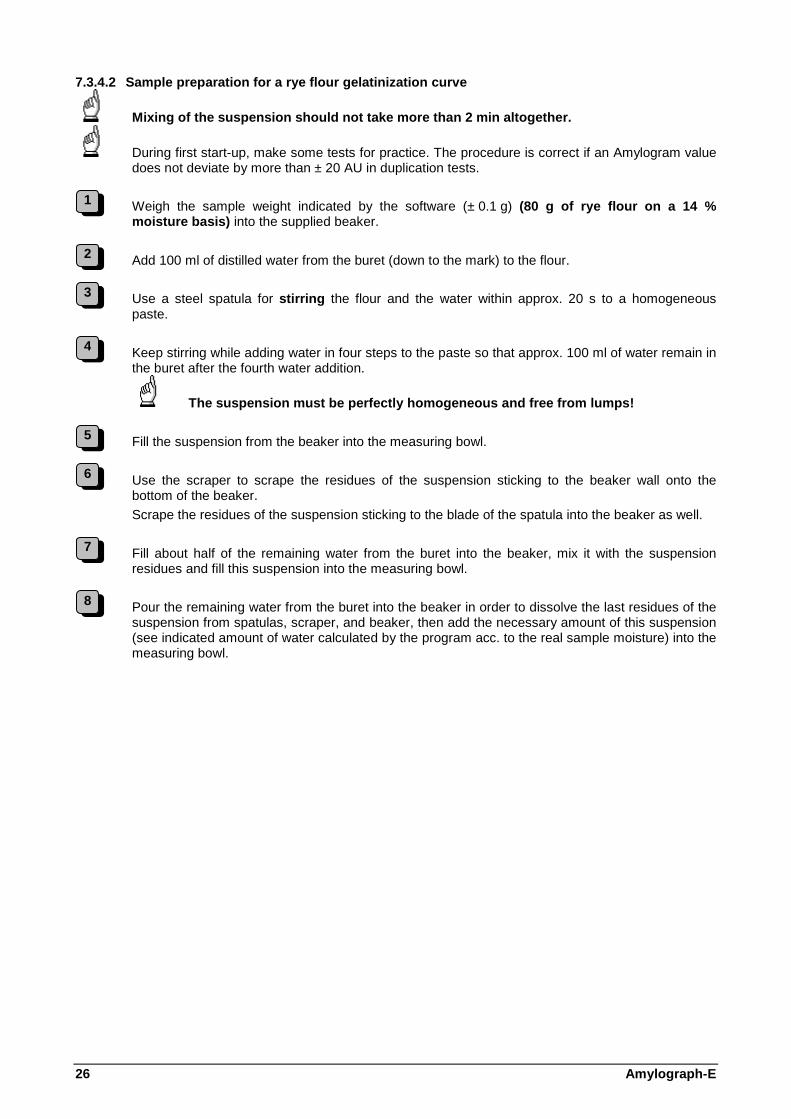
7.3.4.2 Sample preparation for a rye flour gelatini zation curve
Mixing of the suspension should not take more than 2 min altogether.
During first start-up, make some tests for practice. The procedure is correct if an Amylogram value does not deviate by more than ± 20 AU in duplication tests.
Weigh the sample weight indicated by the software (± 0.1 g) (80 g of rye flour on a 14 % moisture basis) into the supplied beaker.
Add 100 ml of distilled water from the buret (down to the mark) to the flour.
Use a steel spatula for stirring the flour and the water within approx. 20 s to a homogeneous
paste.
Keep stirring while adding water in four steps to the paste so that approx. 100 ml of water remain in the buret after the fourth water addition.
The suspension must be perfectly homogeneous and f ree from lumps!
Fill the suspension from the beaker into the measuring bowl.
Use the scraper to scrape the residues of the suspension sticking to the beaker wall onto the bottom of the beaker.
Scrape the residues of the suspension sticking to the blade of the spatula into the beaker as well.
Fill about half of the remaining water from the buret into the beaker, mix it with the suspension residues and fill this suspension into the measuring bowl.
Pour the remaining water from the buret into the beaker in order to dissolve the last residues of the suspension from spatulas, scraper, and beaker, then add the necessary amount of this suspension (see indicated amount of water calculated by the program acc. to the real sample moisture) into the measuring bowl.
1
2
3
4
5
6
7
8

Amylograph-E 27
7.3.4.3 Sample preparation for a wheat wholemeal ge latinization curve
Clean the wheat and separate any coarse particles.
Grind 95 g of the clean wheat on a break mill to meal.
If larger amounts are ground, wheat may settle out!
The degree of fineness of the meal obtained must be constant for all wheat samples to be tested. Deviations in grain size may influence the gelatinization process in the Amylogram.
Determine the water content of the wheat meal.
Weigh the sample weight indicated by the software (± 0.1 g) (90 g of wheat meal on a 14 % moisture basis) into a 1000-ml Erlenmeyer flask.
Add approx. 360 ml of distilled water from the buret.
Close the Erlenmeyer flask and shake it approx. 50 times in 30 s.
The suspension must be perfectly homogeneous and f ree from lumps!
Fill the suspension into the measuring bowl of the Amylograph.
Flush the Erlenmeyer flask with the residual water and add the necessary amount of this suspension (see indicated amount of water calculated by the program acc. to the real sample moisture) into the measuring bowl.
1
2
3
4
5
6
7
8

28 Amylograph-E
7.3.4.4 Sample preparation for a rye wholemeal gela tinization curve
Clean the rye and separate any coarse particles.
Grind 95 g of the clean rye on a break mill to meal.
If larger amounts are ground, rye may settle out!
The degree of fineness of the meal obtained must be constant for all rye samples to be tested. Deviations in grain size may influence the gelatinization process in the Amylogram.
Determine the water content of the rye meal.
Weigh the sample weight indicated by the software (± 0.1 g) (90 g of rye meal on a 14 % moisture basis) into the beaker.
Add 100 ml of distilled water from the full buret (down to the mark) to the meal.
Use the steel spatula for stirring the meal and the water within approx. 20 s to a homogeneous paste.
Keep stirring while adding water in four steps to the paste so that approx. 100 ml of water remain in the buret after the fourth water addition.
The suspension must be perfectly homogeneous and f ree from lumps!
Fill the suspension from the beaker into the measuring bowl.
Use the scraper to scrape the residues of the suspension sticking to the beaker wall onto the bottom of the beaker.
Scrape the residues of the suspension sticking to the blade of the spatula into the beaker as well.
Fill about half of the remaining water from the buret into the beaker, mix it with the suspension residues and fill this suspension into the measuring bowl.
Pour the remaining water from the buret into the beaker in order to dissolve the last residues of the suspension from spatulas, scraper, and beaker, then add the necessary amount of this suspension (see indicated amount of water calculated by the program acc. to the real sample moisture) into the measuring bowl.
7.3.4.5 Summary of procedures for wheat/rye flour a nd wheat/rye meal
Wheat Rye Shake Stir
Flour: 80 g Meal: 90 g Flour: 80 g Meal: 90 g
1
2
3
4
5
6
7
8
9
10
11

Amylograph-E 29
7.3.5 Starting the test
Click the "Start" button in the parameter window (fig. 13) in order to start the test.
When clicking the "Start" button, the measuring he ad must be in its top position!
The system tares automatically, the monitor reads "tare".
Upon completion of taring, you are requested to push the measuring head down into operating position:
Fig. 14
Pull the snapper and push the measuring head down into operating position.
As long as the measuring head is not pushed down after appearance of the above window, the window will flash in red and an acoustic alarm is given.
The temperature controller first heats up to the preset start temperature (fig. 15).
Fig. 15
As soon as this has been reached, the controller starts heating with the preset heating rate up to a final temperature of 93°C which is held for 5 min.
The final temperature of 93°C and the holding time of 5 min are fixed values in the program.
The holding time can be extended by entering a corresponding value in the "Settings" window (menu "Options" - "Settings", index card "General"), see 6.2.4.2, fig. 9
During the test, the diagram is recorded and displayed on-line on the monitor.
1
2
3
4
5

30 Amylograph-E
7.3.6 Displays during the test After test start, the monitor shows a diagram (fig. 16) with two x-axes and a y-axis occupied as follows:
• upper x-axis temperature in °C
• lower x-axis test time in [min]
• y-axis viscosity in AU (= Amylograph units)
Fig. 16
During the test, the torque (viscosity) is recorded and displayed on-line.
For the graphic options, please refer to the separ ate instruction manual of the Amylograph software.
7.3.7 Test time, end of test When the test time has elapsed, data transmission from the Amylograph is stopped automatically.
With the standard parameters
• start temperature 30°C
• heating rate 1.5°C/min
the overal test time is
42 min + 5 min holding time = 47 min
The test can be stopped anytime before expiry of the test time by clicking the "Stop" button (e.g. if the gelatinization maximum has been reached already after 30 min with rye).
After completion of the test, the test is evaluated automatically by means of the software. The test including test conditions, diagram, and evaluation can be printed.
The evaluated test should be saved on the PC.

Amylograph-E 31
7.4 Test evaluation
Details concerning test evaluation are given in th e separate instruction manual of the Amylograph software.
7.4.1 Amylogram After completion of the test, the test is evaluated automatically. The following evaluation points are calculated and displayed in the diagram (fig. 17):
• Beginning of gelatinization
• Gelatinization temperature
• Gelatinization maximum
Fig. 17
7.4.2 Bread rye quality The program permits to check whether the results of a rye sample meet the quality standards for bread rye (gelatinization temperature ≥ 63°C, gelatinization maximum ≥ 200 AU).
Clicking shows the limits for bread rye quality in the diagram:
Fig. 18
In the example shown above, the sample meets the standard quality of bread rye, because the gelatinization temperature is above 63°C and the gelatinization ma ximum is above 200 AU.
Clicking this button in the graphical representation indicates bread rye quality in the tabular representation of the sample, too.
Gelatinization temperature Gelatinization maximum
Beginning of gelatinization
Limits for bread rye quality

32 Amylograph-E
7.5 Cleaning the instrument
After completion of the test, pull the snapper so that the measuring head moves in its top position.
Loosen the bayonet locking of the measuring sensor (while doing so, hold the sensor with your hand! ) and put it into the sample material in the measuring bowl.
Clean the Pt-100 sensor (RTD) with a moist cloth and dry it thoroughly.
Clean the Pt-100 sensor (RTD) before removing the measuring bowl from the support in order to prevent sample material from falling onto the rotary plate.
Attention, take care not to bend or misadjust the Pt-100 sensor (RTD) during cleaning or drying!
Remove the measuring bowl with the sensor from the support by means of the supplied bowl holder and clean both parts with water and the bottle brush supplied.
Before starting the next test, all parts must be p erfectly dry.
1
2
3
4

Amylograph-E 33
8 MAINTENANCE
8.1 Cleaning the bowl and the sensor
The bowl, measuring sensor, and the Pt-100 sensor (RTD) must be perfectly clean and dry before starting a new test!
Thoroughly clean the individual parts with clear water and the supplied bottle brush.
Thoroughly dry all parts.
8.2 Calibration
Correct operation and precise results can only be guaranteed if the instrument is checked with a calibration sample in regular time intervals.
Brabender supplies calibration samples for the following instruments:
• Farinograph
• Extensograph
• Amylograph
• Viskograph
Run the instrument once every year with the calibration sample and compare the results with the calibration curve.
1
2

34 Amylograph-E
9 TROUBLE-SHOOTING
In the following, some examples of possible failures and recommended actions are listed.
Failure Action
When a test has been started, the temperature ramp is not loaded, the temperature remains constant.
Make sure that the temperature controller is not set to "Hold".
After starting, the monitor shows the message: "Device not available. Run demo-test?"
Check whether the correct instrument has been connected (menu "Options" - "Settings", index card "General") and whether the communication ports have been allocated correctly (chapter 6.2.4.2 points 2 + 3).
When a test has been started, no measuring signal is transmitted to the computer. The temperature and torque displays read "0" or any wrong value.
Check whether the correct instrument has been connected (menu "Options" - "Settings", index card "General") and whether the communication ports have been allocated correctly (chapter 6.2.4.2 points 2 + 3).

Amylograph-E 35
10 ACCESSORIES
For handling and operating the instrument as well as for cleaning, useful accessories are supplied with the instrument (see accessories list). In case of loss or wear or wastage, the individual parts can be ordered like spare parts at any time.
11 SPARE PARTS
For all inquiries or orders of spare parts or additional equipment for Brabender test instruments, please always state the model number and the serial number of the instrument for which you require the respective spare parts or additional equipment (see spare parts list).
You will find these numbers on the name plates attached to each instrument.
Your order or inquiry cannot be handled without th ese numbers.
By additionally stating the order number under which you once received the corresponding instrument from Brabender, you can facilitate handling of your order/inquiry even more.
All instruments ever supplied by Brabender are registered in a file. They can, however, only be found with the help of these numbers.
Spare parts can be ordered from Brabender directly or from any local Brabender representative.
12 ANNEX
Lists: Accessories
Spare parts
Supplementary modules
Additional equipment
Curve, wiring diagrams
Please also observe the separate instruction manuals for the other instruments working together in a system.

36 Amylograph-E
Accessories for Amylograph-E
Qty. Ident no. Description
1 2 97 028 beaker 600 ml
1 2 97 029 spatula (stainless steel)
1 2 97 123 set of Allan keys, metric
1 2 97 219 scraper
1 2 97 410 round clamp made of annealed cast iron for stand
1 2 97 411 stand
1 2 97 412 double socket for stand up to 16 mm ø
1 6 11 001 measuring buret 450 cm³
1 6 90 006 measuring bowl
1 6 90 008.001 measuring sensor
1 2 17 560 mains cable
1 2 21 589 USB cable

Amylograph-E 37
Spare parts for Amylograph-E
Ident no. Description
6 79 015 gauge
6 73 005 heating element 500 W, 240 V
6 86 056.004 Pt-100 sensor, EMC
2 17 064 micro switch type PB 1081302, 250 V, 10 A
2 17 188 fuse 5 * 20 mm, 6.3 A/MT, DIN 41571
2 18 182 semi-conductor relay
2 18 183 varistor type V 275 LA 20 A
2 18 230 fuse 6.3 * 32 mm, 16 A/FF
2 21 530 power pack
2 25 398 toothed belt MXL, Z = 267/pitch 0.08" B = ¼"
2 35 206 dc motor with encoder
2 38 247 gas pressure spring
2 41 382 load cell Z6 FD1/5 kg, accuracy 0.1 %
2 41 650 recording electronics
2 41 680 temperature controller 2416 85-264 VAC
2 41 809 4-port-RS232 USB interface Edgeport
6 86 617 spare for 4-Q servo amplifier DES 50/5 Maxon
2 90 020 deep groove ball bearing RV 722X-5/12-J834/1-L2
2 90 040 deep groove ball bearing 6002-2Z/C2
2 21 766 square frame ZB-AZ31
2 21 757 push-button, locking, green
2 21 764 contact block 2 S ZBE-203
2 21 760 fixing flange ZB5 AZ009
2 21 763 LED module, green, 230 V
2 18 871 mains suppression filter FN 360 E
2 18 075 RC combination 0.047µF/47 R

38 Amylograph-E
Supplementary modules for Amylograph-E
Ident no. Description
6 90 042.001 blade for rapid amylogram
6 90 043.001 outer cylinder for rapid amylogram
6 90 062 outer bowl for rapid amylogram
4 35 104 Erlenmeyer flask
4 51 027 adjusting disk d = 45, 2 mm thick
2 73 024 rubber plug grey, 28 * 34 * 35 mm
2 97 029 spatula made of stainlees steel
2 97 690 PP powder hopper 100 mm
2 97 691 Kipp automat, 100 ml

Amylograph-E 39
Additional equipment for Amylograph-E
Ident no. Description
6 14 044 calibration starch with curve

40