Embed Size (px)
Citation preview
System and Network Engineering
Research Project 1
Master of Science Program
Academic year 2008–2009
802.1ah in NetherLight:An application proposal
by
Sevickson KWIDAMAsevickson.kwidama ⇒ os3.nl
UvA Supervisor : Dr. Ir. Cees de Laat
Project Supervisors : Ronald van der Pol
Mark Meijerink
Research Project report for System and Network Engineering, University of Amsterdam, theNetherlands, for RP1 academic year 2008–2009.
This document is c© 2008Sevickson Kwidama | sevickson.kwidama ⇒ os3.nl.
Some rights reserved: this document is licensed under the Creative Commons Attribution 3.0Netherlands license. You are free to use and share this document under the condition that youproperly attribute the original authors. Please see the following address for the full license condi-tions: http://creativecommons.org/licenses/by/3.0/nl/deed.en
Cover image: This image symbolizes the interconnection of different lightpaths in a GOLE, likeNetherLight. Source: http://www.stockxpert.com/.
Version 1.0.0 and compiled with LATEX on February 17, 2009.
Abstract
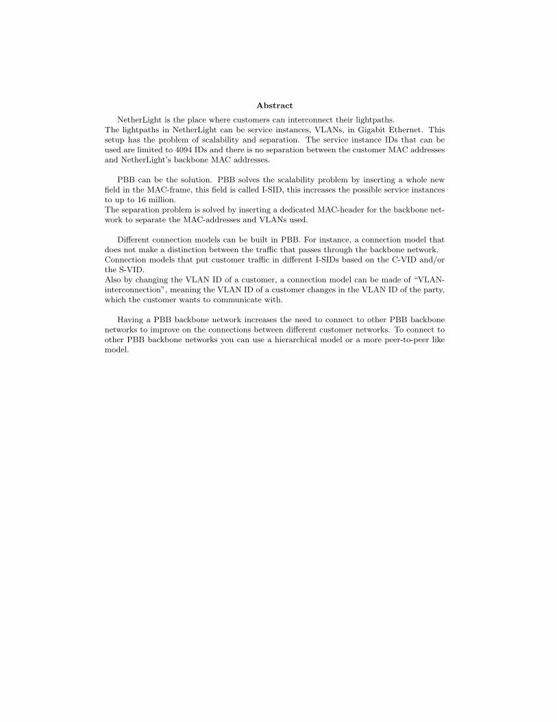
NetherLight is the place where customers can interconnect their lightpaths.The lightpaths in NetherLight can be service instances, VLANs, in Gigabit Ethernet. Thissetup has the problem of scalability and separation. The service instance IDs that can beused are limited to 4094 IDs and there is no separation between the customer MAC addressesand NetherLight’s backbone MAC addresses.
PBB can be the solution. PBB solves the scalability problem by inserting a whole newfield in the MAC-frame, this field is called I-SID, this increases the possible service instancesto up to 16 million.The separation problem is solved by inserting a dedicated MAC-header for the backbone net-work to separate the MAC-addresses and VLANs used.
Different connection models can be built in PBB. For instance, a connection model thatdoes not make a distinction between the traffic that passes through the backbone network.Connection models that put customer traffic in different I-SIDs based on the C-VID and/orthe S-VID.Also by changing the VLAN ID of a customer, a connection model can be made of “VLAN-interconnection”, meaning the VLAN ID of a customer changes in the VLAN ID of the party,which the customer wants to communicate with.
Having a PBB backbone network increases the need to connect to other PBB backbonenetworks to improve on the connections between different customer networks. To connect toother PBB backbone networks you can use a hierarchical model or a more peer-to-peer likemodel.
Contents
1 Introduction 5
2 NetherLight 6
3 PBB 73.1 Operation . . . . . . . . . . . . . . . . . . . . . . . . . . . . . . . . . . . . . . . . . 73.2 Frame Format . . . . . . . . . . . . . . . . . . . . . . . . . . . . . . . . . . . . . . . 9
4 PBB Connection Models 114.1 Configuration . . . . . . . . . . . . . . . . . . . . . . . . . . . . . . . . . . . . . . . 114.2 Transparent . . . . . . . . . . . . . . . . . . . . . . . . . . . . . . . . . . . . . . . . 124.3 Switched . . . . . . . . . . . . . . . . . . . . . . . . . . . . . . . . . . . . . . . . . . 124.4 Retagging . . . . . . . . . . . . . . . . . . . . . . . . . . . . . . . . . . . . . . . . . 134.5 Q-in-Q . . . . . . . . . . . . . . . . . . . . . . . . . . . . . . . . . . . . . . . . . . . 13
5 Multi-Domain 155.1 Hierarchical PBBNs . . . . . . . . . . . . . . . . . . . . . . . . . . . . . . . . . . . 155.2 Peer PBBNs . . . . . . . . . . . . . . . . . . . . . . . . . . . . . . . . . . . . . . . . 16
6 Future Work 17
7 Conclusion 17
8 Acknowledgments 18
Bibliography 19
Appendices 20
A Configuring the PBB Connection Models 20A.1 Transparent Connection Model . . . . . . . . . . . . . . . . . . . . . . . . . . . . . 21
A.1.1 Device Manager . . . . . . . . . . . . . . . . . . . . . . . . . . . . . . . . . 21A.2 Switched Connection Model . . . . . . . . . . . . . . . . . . . . . . . . . . . . . . . 25
A.2.1 Device Manager . . . . . . . . . . . . . . . . . . . . . . . . . . . . . . . . . 25A.3 Retagging Connection Model . . . . . . . . . . . . . . . . . . . . . . . . . . . . . . 26
A.3.1 Device Manager . . . . . . . . . . . . . . . . . . . . . . . . . . . . . . . . . 26A.4 Q-in-Q Connection Model . . . . . . . . . . . . . . . . . . . . . . . . . . . . . . . . 26
A.4.1 Device Manager . . . . . . . . . . . . . . . . . . . . . . . . . . . . . . . . . 26
B Testing 26
List of Tables
1 PBB frame fields explained. . . . . . . . . . . . . . . . . . . . . . . . . . . . . . . . 9
List of Figures
1 GLIF World Map. . . . . . . . . . . . . . . . . . . . . . . . . . . . . . . . . . . . . 62 Frame Encapsulation in BEB . . . . . . . . . . . . . . . . . . . . . . . . . . . . . . 83 Different frame formats used in PBB. . . . . . . . . . . . . . . . . . . . . . . . . . 94 Detailed frame format of PBB. . . . . . . . . . . . . . . . . . . . . . . . . . . . . . 105 Setup used to test PBB connection models. . . . . . . . . . . . . . . . . . . . . . . 116 Transparent Connection Model concept. . . . . . . . . . . . . . . . . . . . . . . . . 127 Switched Connection Model concept. . . . . . . . . . . . . . . . . . . . . . . . . . . 138 Retagging Connection Model concept. . . . . . . . . . . . . . . . . . . . . . . . . . 139 Q-in-Q Connection Model concept 1. . . . . . . . . . . . . . . . . . . . . . . . . . . 1410 Q-in-Q Connection Model concept 2. . . . . . . . . . . . . . . . . . . . . . . . . . . 1411 Hierarchical PBBN example. . . . . . . . . . . . . . . . . . . . . . . . . . . . . . . 1512 Peer PBBN example. . . . . . . . . . . . . . . . . . . . . . . . . . . . . . . . . . . . 1613 Screenshot: NJDM Main window . . . . . . . . . . . . . . . . . . . . . . . . . . . . 2014 Screenshot: Port configuration window . . . . . . . . . . . . . . . . . . . . . . . . . 2115 Screenshot: B-VLAN configuration window . . . . . . . . . . . . . . . . . . . . . . 2216 Screenshot: I-SID configuration window . . . . . . . . . . . . . . . . . . . . . . . . 2317 Screenshot: I-SID endpoint configuration window . . . . . . . . . . . . . . . . . . . 2418 Screenshot: I-SID table window . . . . . . . . . . . . . . . . . . . . . . . . . . . . . 25
4
1 INTRODUCTION
1 Introduction
NetherLight [1] is one of the network exchange points that interconnect different research networksall over the world.NetherLight makes use of lightpaths to connect the different networks to each other. These net-works are connected via SDH/SONET circuits, Virtual Local Area Networks (VLANs) in GigabitEthernet or a combination of both.
When you look at the currently used switching setup of NetherLight, it is clear that they aren’tusing the full potential of NetherLight. The reason for this is that they are using VLAN-taggedand untagged ports.One of the disadvantages of this setup is that there is no separation between the VLANs of thecustomers and the VLANs of NetherLight itself. The solution used, is careful planning of VLANIDs between NetherLight and its customers. This setup can be used as long as the overview staysclear and the network does not grow.
The overview is soon lost in NetherLight, because of the fact that there are different networksconnected to NetherLight. Different VLAN configurations must be coordinated between the net-works and NetherLight. Also VLAN planning is an exhaustive job. The network of NetherLightis still growing making the limitation of 4094 VLAN IDs a problem.
This is the reason to look for other solutions.The IEEE standard 802.1ah [2] implemented as Provider Backbone Bridges (PBB) or Mac-in-Mac(M-in-M) can be the solution for this problem.This standard is a technology that makes it possible to separate the NetherLight backbone VLANsfrom the customers VLANs and dramatically increase the amount of VLANs that can be used. Iwill use the term PBB in the rest of this report.
With PBB as the center of my research I will be looking at different aspects of PBB. The aspectsthat I will be looking at are summarized as research questions below:
1. How can PBB be used to support several connection models in NetherLight?
2. Can PBB be used in a multi-domain environment?
This report is divided as follows:The first part gives some background information about NetherLight in chapter 2.
After discussing the background, PBB and his operational model will be discussed in chapter 3on page 7.The different connection models are discussed in chapter 4 on page 11.The second research question is discussed in chapter 5 on page 15.
Closing this report I will give future work in chapter 6 and some conclusions in chapter 7 onpage 17.
5
2 NETHERLIGHT
2 NetherLight
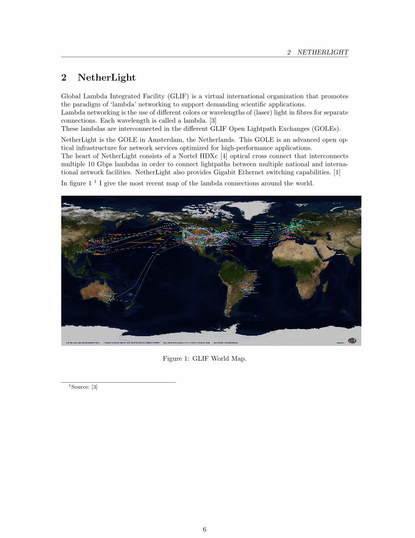
Global Lambda Integrated Facility (GLIF) is a virtual international organization that promotesthe paradigm of ‘lambda’ networking to support demanding scientific applications.Lambda networking is the use of different colors or wavelengths of (laser) light in fibres for separateconnections. Each wavelength is called a lambda. [3]These lambdas are interconnected in the different GLIF Open Lightpath Exchanges (GOLEs).
NetherLight is the GOLE in Amsterdam, the Netherlands. This GOLE is an advanced open op-tical infrastructure for network services optimized for high-performance applications.The heart of NetherLight consists of a Nortel HDXc [4] optical cross connect that interconnectsmultiple 10 Gbps lambdas in order to connect lightpaths between multiple national and interna-tional network facilities. NetherLight also provides Gigabit Ethernet switching capabilities. [1]
In figure 1 1 I give the most recent map of the lambda connections around the world.
Figure 1: GLIF World Map.
1Source: [3]
6
3 PBB
3 PBB
PBB is an architecture and set of protocols for forwarding primarily Ethernet frames of customersover a service providers backbone network, allowing interconnection of multiple networks withoutlosing each customers individually defined VLANs. [5]
Ethernet was initially defined to interconnect computers in a Local Area Network (LAN), withina small organization.Over the years, Ethernet has become vastly popular technology and became the default OpenSystems Interconnection (OSI) Layer 2 mechanism for any data transport.This created the need for extending the Ethernet from a customer LAN bridging network to serviceprovider Metropolitan Area Network (MAN) or the provider bridging network. From this needCarrier Ethernet was born.
Carrier Ethernet is an extension to Ethernet that makes it possible for service providers to extendtheir network, in this case the backbone network, to add scalability, reliability and security, tosupport the growing number of customers.
For this, an encapsulation method using an extra VLAN ID field, called a Service Tag (S-Tag),was added to the Ethernet frame in IEEE 802.1ad standard. Switching, in the network of theservice provider, is based on the S-Tag and destination MAC address. The C-Tag defined in IEEE802.1Q is used to create VLANs in the customer’s network. The technology based on the IEEE802.1ad standard is also known as Q-in-Q or Q-tunneling.
Q-in-Q does not offer true separation of the customer and provider’s network, but is merely a wayto overcome the limitations of the VLAN identifier space of the IEEE 802.1Q standard. There’sstill the problem of having too little control of the MAC addresses, since Q-in-Q forwarding is stillbased on the customer’s destination addresses. [5]
From the urgency of providing a better mechanism than Q-in-Q for service providers, PBB wasborn.Instead of using a single S-Tag field, PBB encapsulates the customer’s frame in a new MAC-header. This has the benefit that it completely separates the customer’s network from the serviceprovider’s.Another benefit of PBB is the Backbone Service Instance Identifier (I-SID) field. This field relievesthe service provider of the scaling problem of VLANs by giving the service provider the possibilityto create up to 16 million services.By using the I-SIDs for service identification, VLANs in the backbone network can be used tosegregate the service providers network into regions to simplify traffic engineering. [6]
3.1 Operation
A service provider’s backbone network, configured with PBB, is called a Provider BackboneBridged Network (PBBN). PBBN has basically two network components: Backbone Edge Bridges(BEBs) and Backbone Core Bridges (BCBs).The BEB is the ingress and egress point of customer MAC-frames in the PBBN. BEB is dividedin theory in two components: the I-Component and the B-Component [7].The I-Component is for I-SIDs and customer separation. The B-Component is for the forward-ing of the customer frames in the backbone. [8] These two components can also be in separateBEBs. An example of this setup is when a customer controls a BEB. That BEB then sends I-tagged frames, frames processed by the I-Component, to the BEB under provider control and theprovider BEB then processes the I-tagged frame through the B-Component.
The interface of the BEB that is connected to the customer is called the User to Network Interface(UNI). UNI is basically the Customer Network Port (CNP) of the I-Component.
The I-Component identifies the service instance for that specific frame and is responsible forthe customer separation. This component classifies and associates the customer frame with an
7
3.1 Operation 3 PBB
I-SID. [8] Then a Backbone Service Instance Tag (I-Tag) containing the I-SID is inserted intothe frame. Also a Backbone Source MAC Address (B-MAC SA) and a Backbone DestinationMAC Address (B-MAC DA) is prepended to that frame. A new Frame Check Sequence (FCS) iscalculated for the frame replacing the old FCS.The different fields of the PBB MAC-frame will be discussed in section 3.2 on the next page.The I-tagged frame leaves the I-Component via the Provider Instance Port (PIP).
After the I-tagged frame leaves the PIP, it enters the B-Component through the Customer Back-bone Port (CBP).The B-Component is responsible for forwarding of the customer frames through the PBBN.This component adds the B-Tag to the frame. The B-Tag contains the ID of the PBB networkVLAN that carries the traffic for this service instance. [8]The frame leaves the B-Component via the Provider Network Port (PNP) and enters the backbonenetwork.
Another implementation of the I-Component and B-Component, is where the I-Component addsthe I-Tag and the B-Component adds the backbone MAC-addresses and B-Tag.
When the frame reaches the egress BEB it does all these steps in reverse.
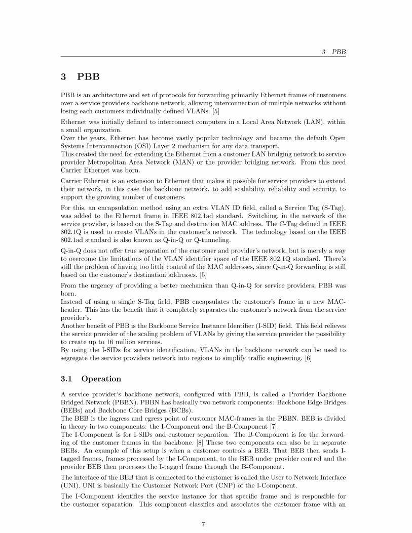
In figure 2 the encapsulation of a MAC-frame in the different components is displayed.
Figure 2: Frame Encapsulation in BEB
The BCBs do not have to be “PBB-aware”, they see the frames as normal MAC-frames andforward the frames according to their own forwarding tables.
8
3.2 Frame Format 3 PBB
3.2 Frame Format
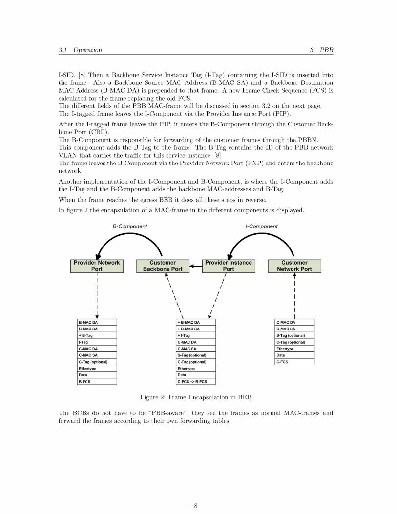
When you look at the PBB frame format you can see why PBB has the name Mac-in-Mac. PBBencapsulates the whole frame with the customer MAC-header included, in a MAC-header of itsown.Figure 3 gives an overview of the PBB frame and how it compares to other frames. The otherframes in this figure, IEEE 802.3 (Ethernet) and 802.1Q (VLAN tagging) and 802.1ad (ProviderBridging) MAC frames, are Ethernet frames that can be encapsulated in PBB.
Figure 3: Different frame formats used in PBB.
The S-Tag in the 802.1ad frame in the figure above, is removed from the PBB frame when itarrives at the ingress BEB and added again at the egress BEB.The PBB frame given in figure 3 is divided as follows:
Field Size Description(bits)
B-DA 48 This is the MAC-address of the PNP of the egress BEB
B-SA 48 The MAC-address of the PNP of the source BEB
B-Tag 32 Backbone tag containing 802.1ah Backbone VLAN ID and it’sTag Protocol Identifier (TPID), (Value = 0x88a8)
I-Tag 48 Instance tag containing the I-SID and it’s TPID (Value = 0x88e7).This tag also contains the encapsulated MAC DA and MAC SA,given below, of the customer when the PBB encapsulates Ethernet
MAC DA 48 Encapsulated customer Destination Address
MAC SA 48 Encapsulated customer Source Address
C-Tag 32 Customer tag containing 802.1Q VLAN ID (C-VID) and it’s TPID(Value = 0x8100), this field is optional
Ethertype 16 This is the data type of the customer data
Data 368-72000 Customer data, the size is including jumbo frames
FCS 32 Checksum to detect alterations in the data of the frame
Table 1: PBB frame fields explained.
9
3.2 Frame Format 3 PBB
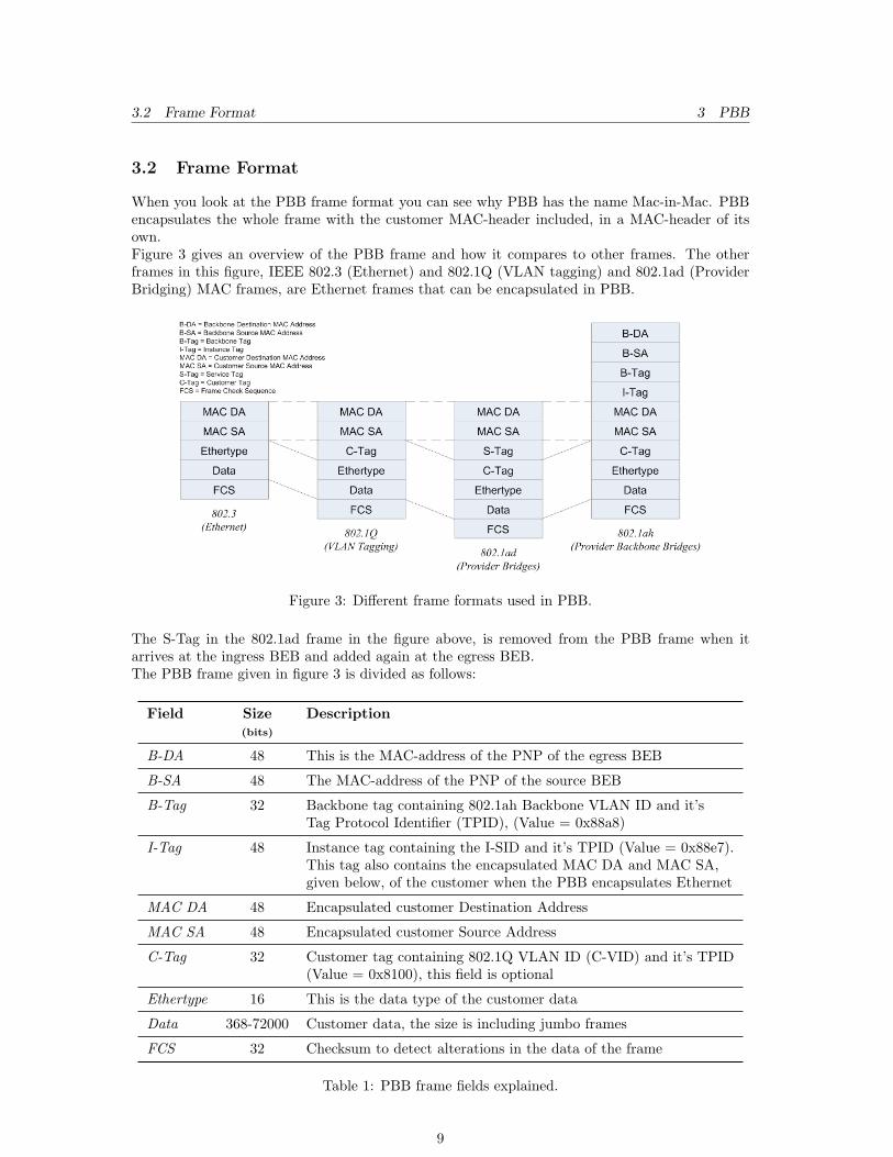
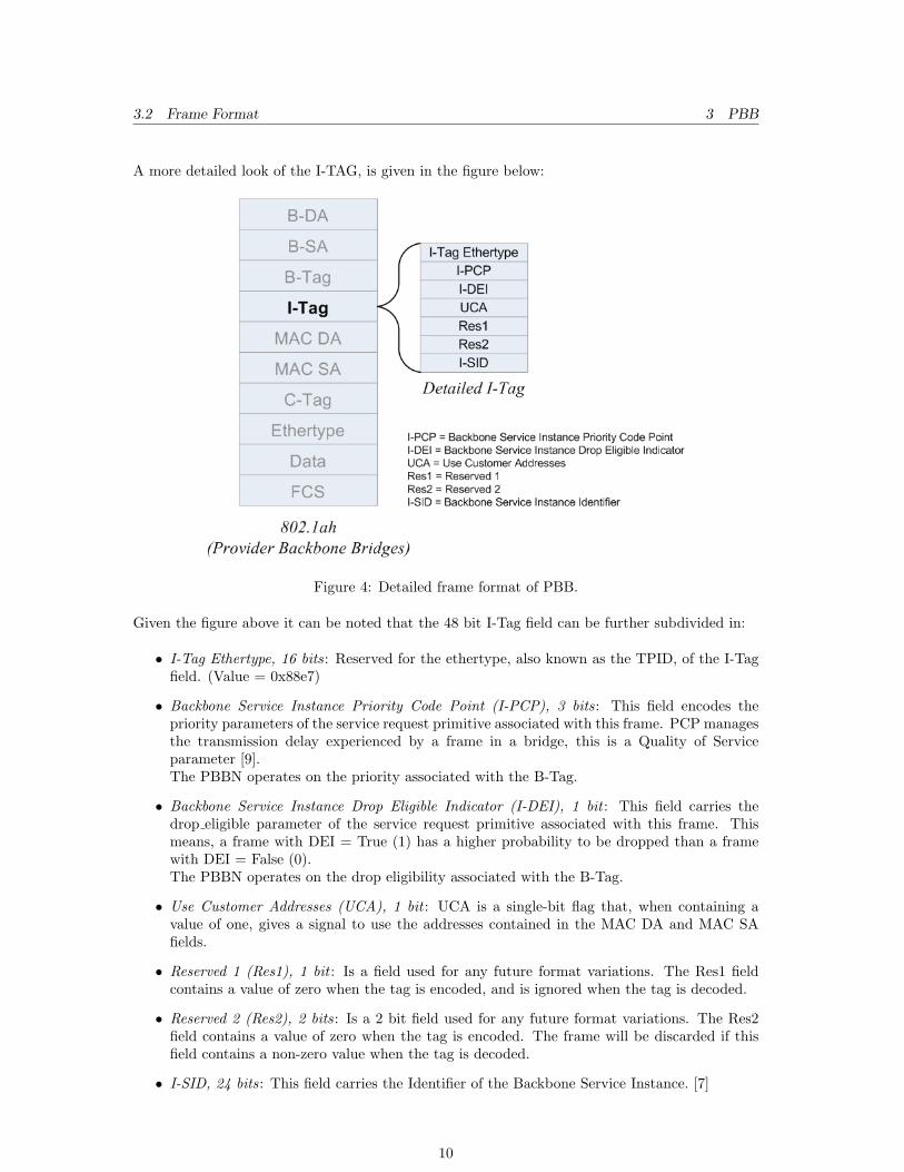
A more detailed look of the I-TAG, is given in the figure below:
Figure 4: Detailed frame format of PBB.
Given the figure above it can be noted that the 48 bit I-Tag field can be further subdivided in:
• I-Tag Ethertype, 16 bits: Reserved for the ethertype, also known as the TPID, of the I-Tagfield. (Value = 0x88e7)
• Backbone Service Instance Priority Code Point (I-PCP), 3 bits: This field encodes thepriority parameters of the service request primitive associated with this frame. PCP managesthe transmission delay experienced by a frame in a bridge, this is a Quality of Serviceparameter [9].The PBBN operates on the priority associated with the B-Tag.
• Backbone Service Instance Drop Eligible Indicator (I-DEI), 1 bit : This field carries thedrop eligible parameter of the service request primitive associated with this frame. Thismeans, a frame with DEI = True (1) has a higher probability to be dropped than a framewith DEI = False (0).The PBBN operates on the drop eligibility associated with the B-Tag.
• Use Customer Addresses (UCA), 1 bit : UCA is a single-bit flag that, when containing avalue of one, gives a signal to use the addresses contained in the MAC DA and MAC SAfields.
• Reserved 1 (Res1), 1 bit : Is a field used for any future format variations. The Res1 fieldcontains a value of zero when the tag is encoded, and is ignored when the tag is decoded.
• Reserved 2 (Res2), 2 bits: Is a 2 bit field used for any future format variations. The Res2field contains a value of zero when the tag is encoded. The frame will be discarded if thisfield contains a non-zero value when the tag is decoded.
• I-SID, 24 bits: This field carries the Identifier of the Backbone Service Instance. [7]
10
4 PBB CONNECTION MODELS
4 PBB Connection Models
PBB has different connection models that can be applied to a specific network configuration. Thedifferent connection models are:
Transparent Uses one I-SID regardless of the tagged or untagged traffic from the customer;
Switched Separates customer traffic to different I-SIDs, according to the Customer’s VLAN IDs(C-VIDs);
Retagging Changes the customer’s VLAN ID in the frame to forward the frame to a differentVLAN;
Q-in-Q Puts frames in I-SIDs depending on the Service VLAN ID (S-VID) in the frame ordepending on the S-VID and C-VID.
The different connection models will be discussed theoretically in this chapter and the configura-tions used for testing are given in Appendix A on page 20.
4.1 Configuration
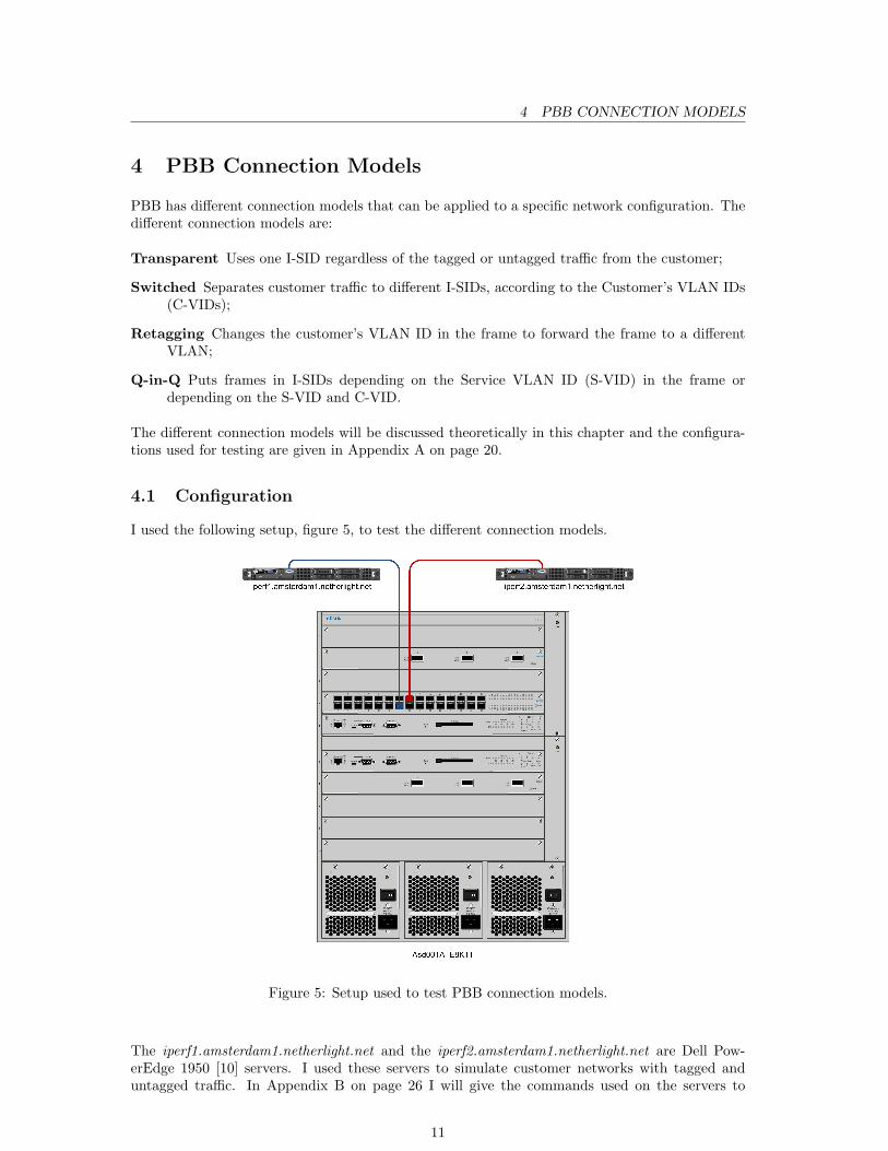
I used the following setup, figure 5, to test the different connection models.
Figure 5: Setup used to test PBB connection models.
The iperf1.amsterdam1.netherlight.net and the iperf2.amsterdam1.netherlight.net are Dell Pow-erEdge 1950 [10] servers. I used these servers to simulate customer networks with tagged anduntagged traffic. In Appendix B on page 26 I will give the commands used on the servers to
11
4.2 Transparent 4 PBB CONNECTION MODELS
generate tagged and untagged traffic and test the different setups.The main purpose of these servers is throughput testing, thus the name Iperf. I will use theseservers to generate tagged and untagged traffic, consisting of ping requests and ping responses.
The Asd001A E8K1T is a Nortel Metro Ethernet Routing Switch (MERS) 8600 [11] with PBBcapabilities. The firmware version installed at the time of testing was 5.0.0.1.I will use this switch to simulate all the connection models given.
The connection models that I explain in the following sections are largely based on my experiencewith the Nortel MERS 8600 switch and the different service types that can be configured on theswitch.
4.2 Transparent
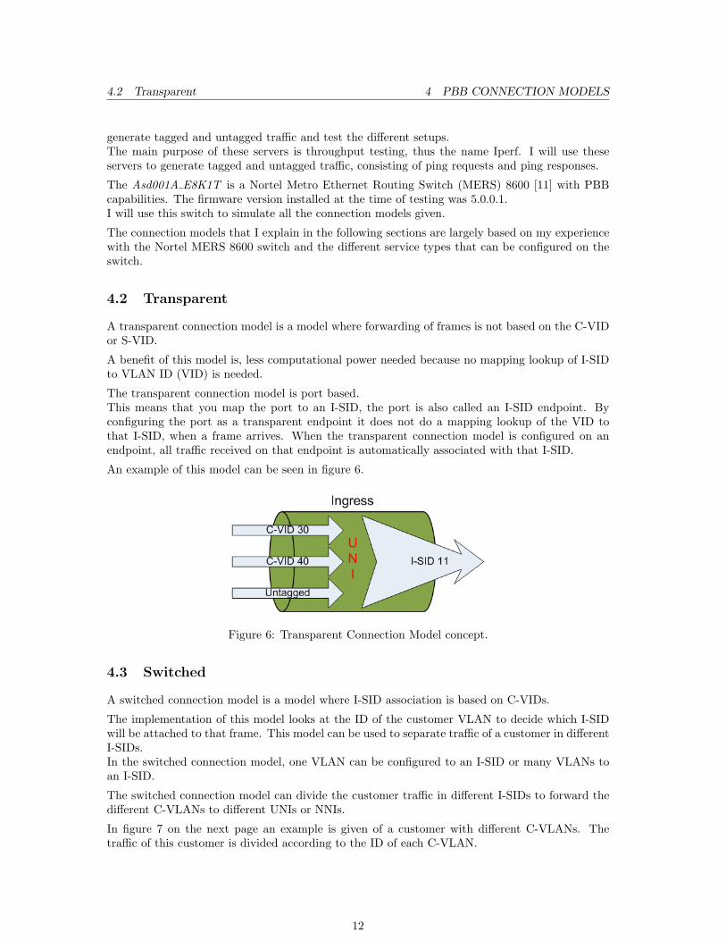
A transparent connection model is a model where forwarding of frames is not based on the C-VIDor S-VID.
A benefit of this model is, less computational power needed because no mapping lookup of I-SIDto VLAN ID (VID) is needed.
The transparent connection model is port based.This means that you map the port to an I-SID, the port is also called an I-SID endpoint. Byconfiguring the port as a transparent endpoint it does not do a mapping lookup of the VID tothat I-SID, when a frame arrives. When the transparent connection model is configured on anendpoint, all traffic received on that endpoint is automatically associated with that I-SID.
An example of this model can be seen in figure 6.
Figure 6: Transparent Connection Model concept.
4.3 Switched
A switched connection model is a model where I-SID association is based on C-VIDs.
The implementation of this model looks at the ID of the customer VLAN to decide which I-SIDwill be attached to that frame. This model can be used to separate traffic of a customer in differentI-SIDs.In the switched connection model, one VLAN can be configured to an I-SID or many VLANs toan I-SID.
The switched connection model can divide the customer traffic in different I-SIDs to forward thedifferent C-VLANs to different UNIs or NNIs.
In figure 7 on the next page an example is given of a customer with different C-VLANs. Thetraffic of this customer is divided according to the ID of each C-VLAN.
12
4.4 Retagging 4 PBB CONNECTION MODELS
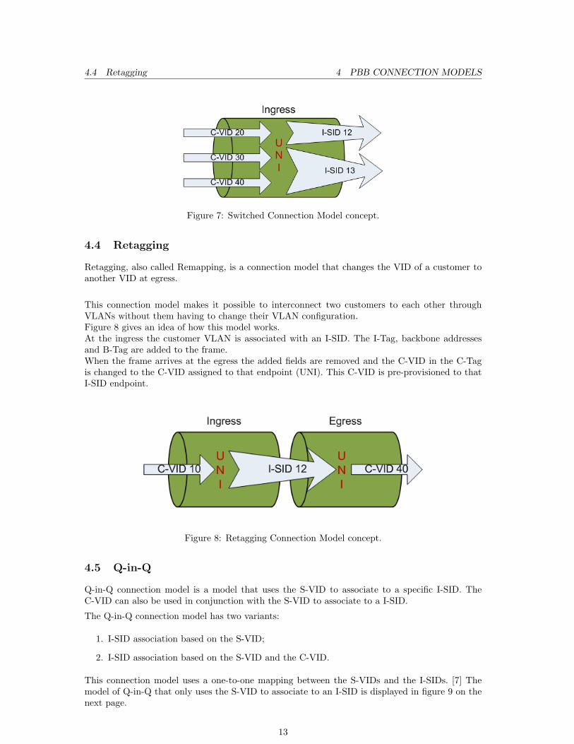
Figure 7: Switched Connection Model concept.
4.4 Retagging
Retagging, also called Remapping, is a connection model that changes the VID of a customer toanother VID at egress.
This connection model makes it possible to interconnect two customers to each other throughVLANs without them having to change their VLAN configuration.Figure 8 gives an idea of how this model works.At the ingress the customer VLAN is associated with an I-SID. The I-Tag, backbone addressesand B-Tag are added to the frame.When the frame arrives at the egress the added fields are removed and the C-VID in the C-Tagis changed to the C-VID assigned to that endpoint (UNI). This C-VID is pre-provisioned to thatI-SID endpoint.
Figure 8: Retagging Connection Model concept.
4.5 Q-in-Q
Q-in-Q connection model is a model that uses the S-VID to associate to a specific I-SID. TheC-VID can also be used in conjunction with the S-VID to associate to a I-SID.
The Q-in-Q connection model has two variants:
1. I-SID association based on the S-VID;
2. I-SID association based on the S-VID and the C-VID.
This connection model uses a one-to-one mapping between the S-VIDs and the I-SIDs. [7] Themodel of Q-in-Q that only uses the S-VID to associate to an I-SID is displayed in figure 9 on thenext page.
13
4.5 Q-in-Q 4 PBB CONNECTION MODELS
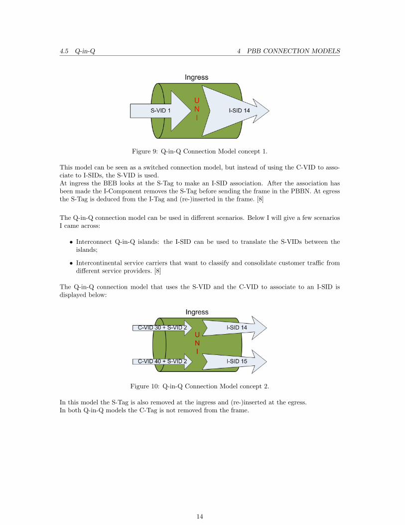
Figure 9: Q-in-Q Connection Model concept 1.
This model can be seen as a switched connection model, but instead of using the C-VID to asso-ciate to I-SIDs, the S-VID is used.At ingress the BEB looks at the S-Tag to make an I-SID association. After the association hasbeen made the I-Component removes the S-Tag before sending the frame in the PBBN. At egressthe S-Tag is deduced from the I-Tag and (re-)inserted in the frame. [8]
The Q-in-Q connection model can be used in different scenarios. Below I will give a few scenariosI came across:
• Interconnect Q-in-Q islands: the I-SID can be used to translate the S-VIDs between theislands;
• Intercontinental service carriers that want to classify and consolidate customer traffic fromdifferent service providers. [8]
The Q-in-Q connection model that uses the S-VID and the C-VID to associate to an I-SID isdisplayed below:
Figure 10: Q-in-Q Connection Model concept 2.
In this model the S-Tag is also removed at the ingress and (re-)inserted at the egress.In both Q-in-Q models the C-Tag is not removed from the frame.
14
5 MULTI-DOMAIN
5 Multi-Domain
Now that the connection models have been discussed, I will discuss the second research questionfor this project:
Can 802.1ah be used in a multi-domain environment?
A multi-domain environment is an environment with multiple PBB networks, each operated bydifferent administrative domains. The different networks, PBBNs, are interconnected via a MetroEthernet Forum (MEF) External Network to Network Interface (E-NNI). [7]It is necessary to look at multi-domain environment possibilities when you want to scale the PBBNbeyond organizations boundaries.
There are two possibilities when looking at interconnection between different PBBNs:
1. Hierarchical PBBNs
2. Peer PBBNs
5.1 Hierarchical PBBNs
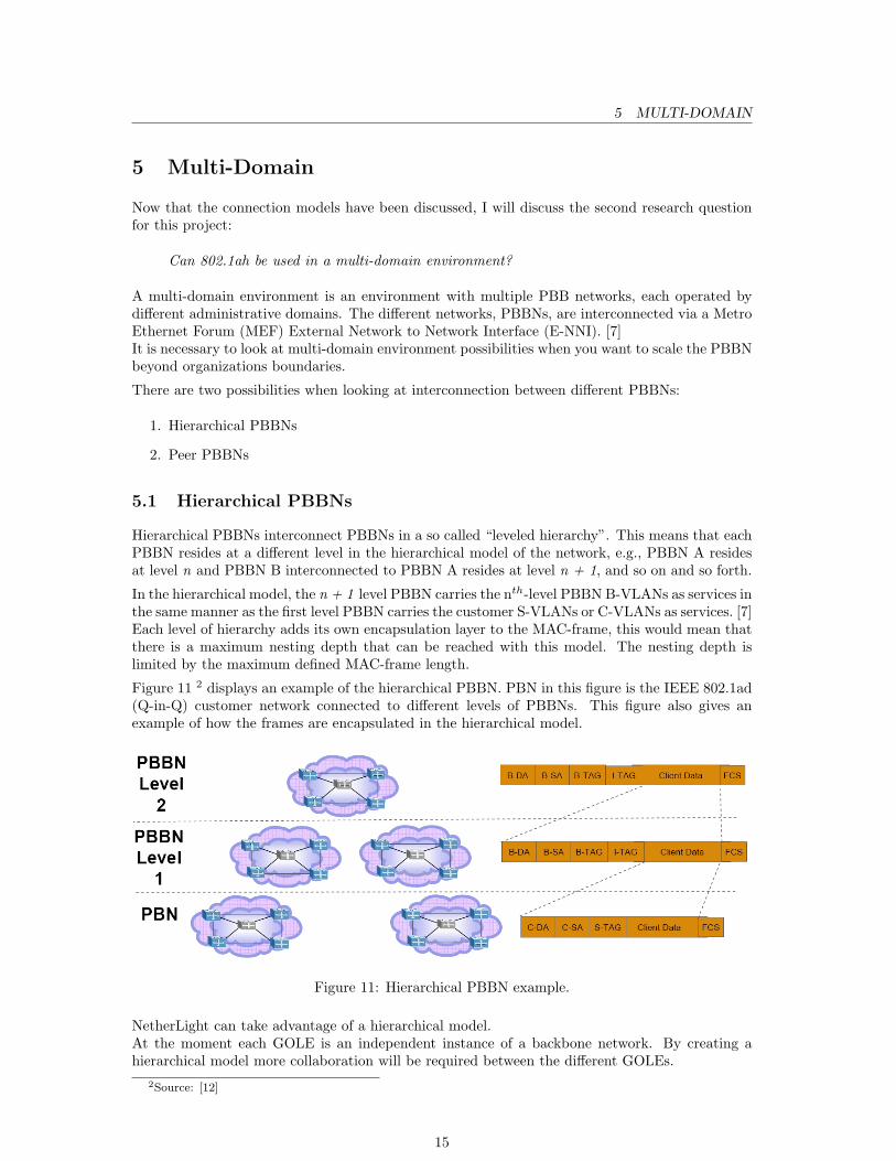
Hierarchical PBBNs interconnect PBBNs in a so called “leveled hierarchy”. This means that eachPBBN resides at a different level in the hierarchical model of the network, e.g., PBBN A residesat level n and PBBN B interconnected to PBBN A resides at level n + 1, and so on and so forth.
In the hierarchical model, the n + 1 level PBBN carries the nth-level PBBN B-VLANs as services inthe same manner as the first level PBBN carries the customer S-VLANs or C-VLANs as services. [7]Each level of hierarchy adds its own encapsulation layer to the MAC-frame, this would mean thatthere is a maximum nesting depth that can be reached with this model. The nesting depth islimited by the maximum defined MAC-frame length.
Figure 11 2 displays an example of the hierarchical PBBN. PBN in this figure is the IEEE 802.1ad(Q-in-Q) customer network connected to different levels of PBBNs. This figure also gives anexample of how the frames are encapsulated in the hierarchical model.
Figure 11: Hierarchical PBBN example.
NetherLight can take advantage of a hierarchical model.At the moment each GOLE is an independent instance of a backbone network. By creating ahierarchical model more collaboration will be required between the different GOLEs.
2Source: [12]
15
5.2 Peer PBBNs 5 MULTI-DOMAIN
A disadvantage of this model can be the creation of “super-GOLEs”, this can have a wrong effecton GOLEs. Creating the idea that some GOLEs are more important than others, can become anobstacle in the collaboration between GOLEs.
The nesting depth limitation can be another disadvantage, but the use of jumbo frames andcontrolling the depth levels of GOLEs can nullify this disadvantage.
5.2 Peer PBBNs
The other multi-domain environment model is called Peer PBBNs. In this model the PBBNs areinterconnected as independent peers with no knowledge of the B-VLANs of the other PBBN.
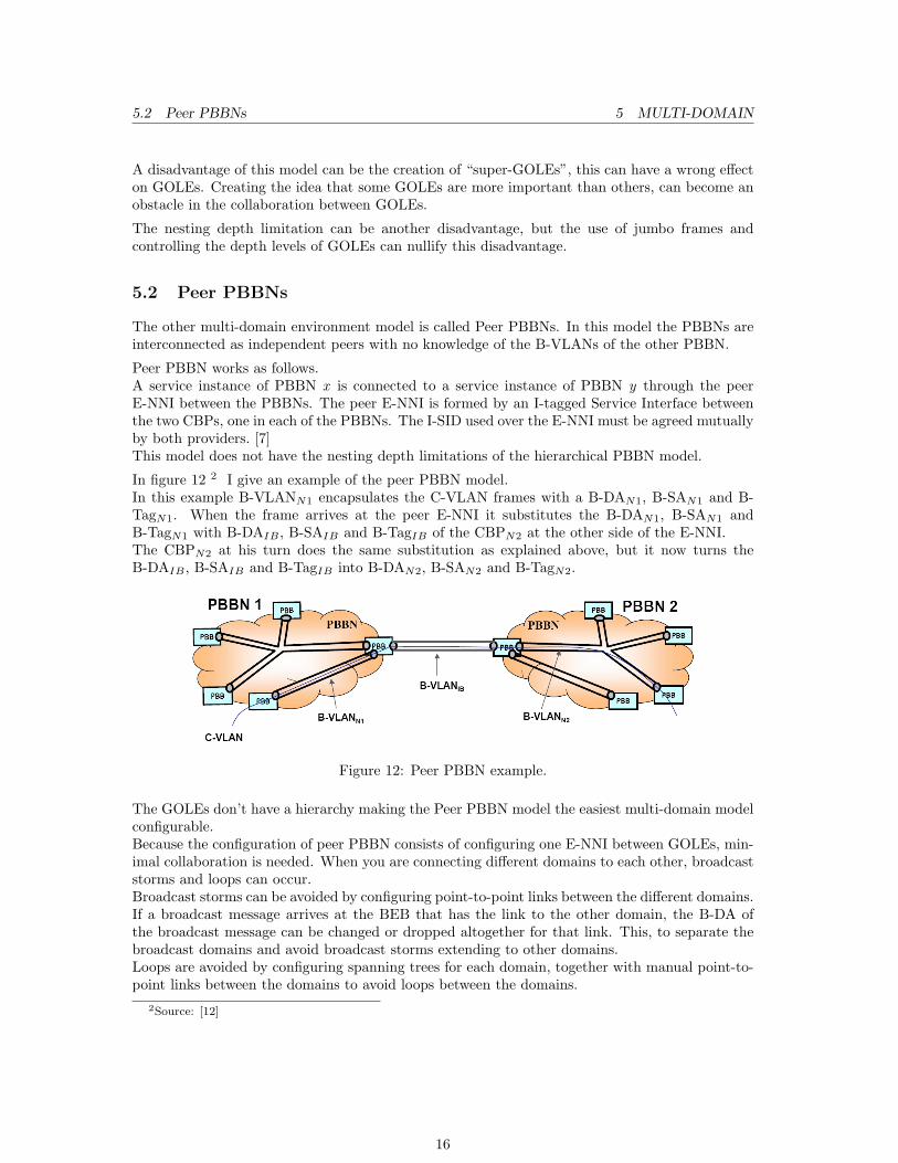
Peer PBBN works as follows.A service instance of PBBN x is connected to a service instance of PBBN y through the peerE-NNI between the PBBNs. The peer E-NNI is formed by an I-tagged Service Interface betweenthe two CBPs, one in each of the PBBNs. The I-SID used over the E-NNI must be agreed mutuallyby both providers. [7]This model does not have the nesting depth limitations of the hierarchical PBBN model.
In figure 12 2 I give an example of the peer PBBN model.In this example B-VLANN1 encapsulates the C-VLAN frames with a B-DAN1, B-SAN1 and B-TagN1. When the frame arrives at the peer E-NNI it substitutes the B-DAN1, B-SAN1 andB-TagN1 with B-DAIB , B-SAIB and B-TagIB of the CBPN2 at the other side of the E-NNI.The CBPN2 at his turn does the same substitution as explained above, but it now turns theB-DAIB , B-SAIB and B-TagIB into B-DAN2, B-SAN2 and B-TagN2.
Figure 12: Peer PBBN example.
The GOLEs don’t have a hierarchy making the Peer PBBN model the easiest multi-domain modelconfigurable.Because the configuration of peer PBBN consists of configuring one E-NNI between GOLEs, min-imal collaboration is needed. When you are connecting different domains to each other, broadcaststorms and loops can occur.Broadcast storms can be avoided by configuring point-to-point links between the different domains.If a broadcast message arrives at the BEB that has the link to the other domain, the B-DA ofthe broadcast message can be changed or dropped altogether for that link. This, to separate thebroadcast domains and avoid broadcast storms extending to other domains.Loops are avoided by configuring spanning trees for each domain, together with manual point-to-point links between the domains to avoid loops between the domains.
2Source: [12]
16
7 CONCLUSION
6 Future Work
Regarding future work, testing of the configurations of the Q-in-Q Connection Model given inAppendix A.4 on page 26 is a good idea. This, to make sure that the configuration of Q-in-Qworks. Because of time constraints I could not test them.
There was no clear instruction on how to configure the NNI ports between switches in the back-bone network. A study must be done in the configuration of NNI.
The multi-domain environments described in the previous chapter can be configured in a test-setup to document the necessary steps needed to implement them.
PBB also has the capability of encapsulating other transport technologies besides Ethernet. Atthe moment it seems, PBB is more focused on Ethernet. Maybe in the near future a study canbe done in the possibilities of encapsulating other transport technologies in PBB. This might beuseful in integrating PBB in the NetherLight network.
A testing environment should be setup for prolonged testing of PBB, with actual customer traffic.This setup can give more insight in the real-life performance of PBB.By using actual customer traffic a phased integration in the NetherLight backbone can be achieved.The VIDs currently used in NetherLight’s backbone should be mapped to I-SIDs to separatecustomer traffic from backbone traffic.
7 Conclusion
First I will answer the research questions that I gave in the Introduction. After that I will givesome overall PBB in NetherLight conclusions based on my findings.
How can PBB be used to support several connection models in NetherLight?Setup of PBB is based on endpoint configuration. This makes PBB flexible in choosingthe connection model, best suiting the situation.
After configuring the different connection models I can say that PBB can be configured and main-tained with the least amount of effort. Configuration must only be done on the ingress and egressof the backbone network making the service interruption minimal.
The connection model for a customer can be chosen according to the customers needs.
Can PBB be used in a multi-domain environment?Yes, it can!
At the moment the Peer PBBN multi-domain environment model is the easiest to configure andmaintain between GOLEs.
Concluding I would say that PBB is a young technology but mature enough to be used in prolongedtesting environments. If positive results are achieved, implementation in NetherLight’s backbonenetwork can follow.
17

8 ACKNOWLEDGMENTS
8 Acknowledgments
Dear reader,
First and foremost I would like to give my praise to God for giving me life and this opportunity.
I would like to express my gratitude to my two supervisors Ronald van der Pol and Mark Meijerinkfor their time and guidance.I would also like to thank Gerard Jacobs for his input regarding PBB and the Nortel MERS 8600.
I thank dr. C. Koymans, J. van Ginkel and E. Schatborn for giving me the opportunity to do thestudy System and Network Engineering (SNE).Dr. Ir. C. de Laat for the choice of this Research Project and his advice.
Last but not least I would like to thank my parents for their time spent reviewing this paper.
With kind regards,
Sevickson Kwidama
18
REFERENCES REFERENCES
References
[1] SURFnet. NetherLight. http://www.surfnet.nl/nl/Thema/netherlight/Pages/AboutNetherLight.aspx.
[2] IEEE. 802.1ah - Provider Backbone Bridges. http://www.ieee802.org/1/pages/802.1ah.html.
[3] Global Lambda Integrated Facility. GLIF. http://www.glif.is/.
[4] Nortel. Optical Cross Connect HDXc. http://www2.nortel.com/go/product_content.jsp?segId=0&catId=0&parId=0&prod_id=9138.
[5] Wikipedia. Wikipedia, the free encyclopedia. http://en.wikipedia.org/.
[6] Nortel. Provider Backbone Bridges bring massive service scalability to Ethernet. http://www.nortel.com/solutions/collateral/nn120620.pdf.
[7] Virtual Bridged Local Area Networks. Amendment 7: Provider Backbone Bridges. IEEE,June 2008. ISBN 973-07381-5762-7 STD95803.
[8] Nortel. Nortel Metro Ethernet Routing Switch 8600 Fundamentals. Technical Report Release5.1, July 2008.
[9] Virtual Bridged Local Area Networks. IEEE, December 2005. ISBN 0-7381-4877-6 SS95508.
[10] Dell. Dell Poweredge 1950. http://www1.ap.dell.com/content/products/productdetails.aspx/pedge_1950.
[11] Nortel. Metro Ethernet Routing Switch 8600. http://www.nortel.com/mers8600.
[12] Paul Bottorff. IEEE 802.1ah Update, November 2005. http://www.ieee802.org/1/files/public/docs2005/ah-bottorff-models-v1-1105.pdf.
[13] Nortel. Java Device Manager. http://support.nortel.com/go/main.jsp?cscat=SOFTWARE&poid=12261.
19
A CONFIGURING THE PBB CONNECTION MODELS
Appendices
A Configuring the PBB Connection Models
The configuration options that I will give below are using the Nortel Java Device Manager GUI.
The generic steps needed to configure the different connection models are:
1. Configure the interface ports (UNIs)
2. Configure the Backbone VLAN
3. Create an I-SID
4. Associate the I-SID to I-SID endpoints (UNIs)
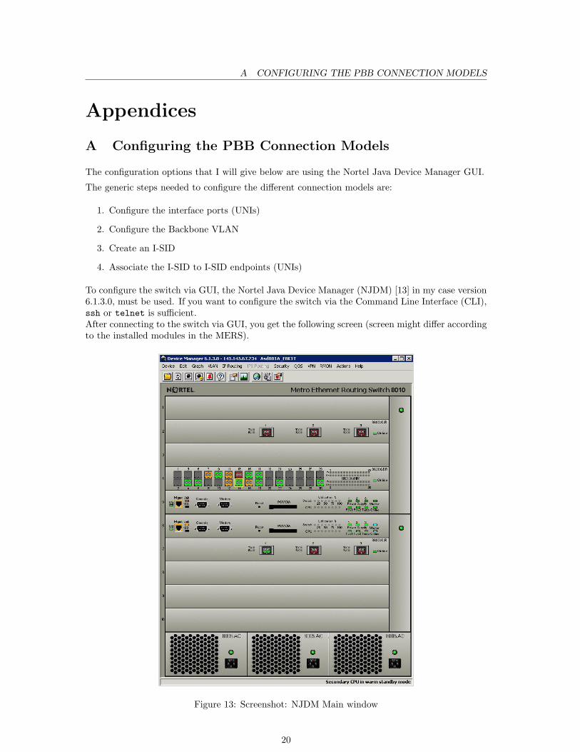
To configure the switch via GUI, the Nortel Java Device Manager (NJDM) [13] in my case version6.1.3.0, must be used. If you want to configure the switch via the Command Line Interface (CLI),ssh or telnet is sufficient.After connecting to the switch via GUI, you get the following screen (screen might differ accordingto the installed modules in the MERS).
Figure 13: Screenshot: NJDM Main window
20

A.1 Transparent Connection Model A CONFIGURING THE PBB CONNECTION MODELS
The configurations that will be given in the next sections are the minimal options needed toconfigure the different connection models. Next to explaining the fields that I used, I give thevariables that were used, between (variable)
A.1 Transparent Connection Model
A.1.1 Device Manager
To configure a port you double-click on the desired port in the Device Manager. And a configu-ration window opens, figure 14 gives a part of that window.
Figure 14: Screenshot: Port configuration window
In the window in figure 14 the following fields need to be changed in the Interface tab to configurethe ports, in my case port 4/14 and 4/15, for the transparent connection model:
Name: A name for the port (RP802.1ah 11/2008)
InterfaceType: The type of the interface (uni)
21
A.1 Transparent Connection Model A CONFIGURING THE PBB CONNECTION MODELS
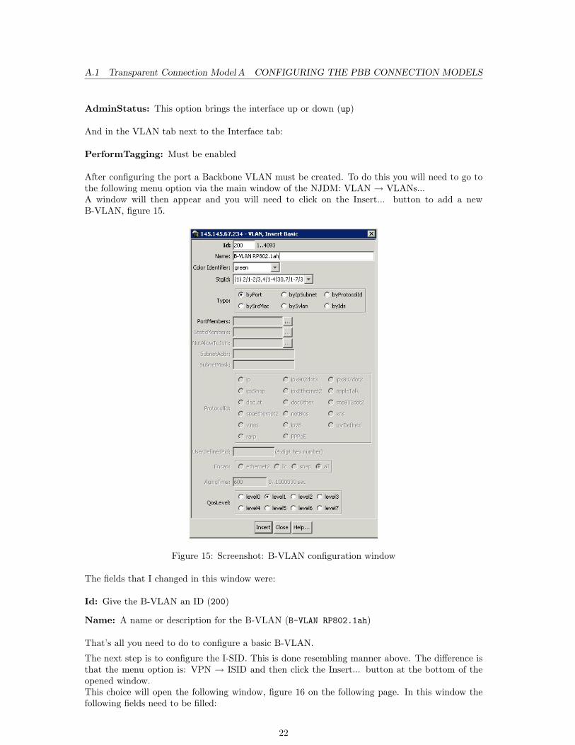
AdminStatus: This option brings the interface up or down (up)
And in the VLAN tab next to the Interface tab:
PerformTagging: Must be enabled
After configuring the port a Backbone VLAN must be created. To do this you will need to go tothe following menu option via the main window of the NJDM: VLAN → VLANs...A window will then appear and you will need to click on the Insert... button to add a newB-VLAN, figure 15.
Figure 15: Screenshot: B-VLAN configuration window
The fields that I changed in this window were:
Id: Give the B-VLAN an ID (200)
Name: A name or description for the B-VLAN (B-VLAN RP802.1ah)
That’s all you need to do to configure a basic B-VLAN.
The next step is to configure the I-SID. This is done resembling manner above. The difference isthat the menu option is: VPN → ISID and then click the Insert... button at the bottom of theopened window.This choice will open the following window, figure 16 on the following page. In this window thefollowing fields need to be filled:
22
A.1 Transparent Connection Model A CONFIGURING THE PBB CONNECTION MODELS
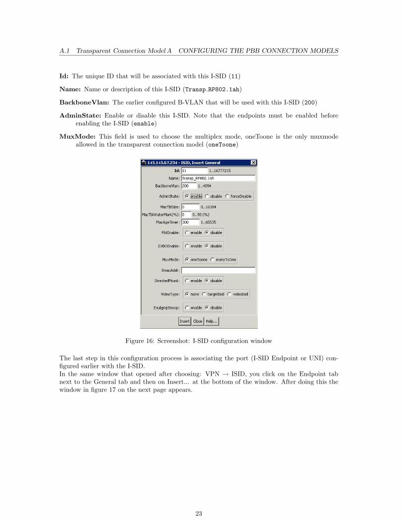
Id: The unique ID that will be associated with this I-SID (11)
Name: Name or description of this I-SID (Transp RP802.1ah)
BackboneVlan: The earlier configured B-VLAN that will be used with this I-SID (200)
AdminState: Enable or disable this I-SID. Note that the endpoints must be enabled beforeenabling the I-SID (enable)
MuxMode: This field is used to choose the multiplex mode, oneToone is the only muxmodeallowed in the transparent connection model (oneToone)
Figure 16: Screenshot: I-SID configuration window
The last step in this configuration process is associating the port (I-SID Endpoint or UNI) con-figured earlier with the I-SID.In the same window that opened after choosing: VPN → ISID, you click on the Endpoint tabnext to the General tab and then on Insert... at the bottom of the window. After doing this thewindow in figure 17 on the next page appears.
23
A.1 Transparent Connection Model A CONFIGURING THE PBB CONNECTION MODELS
Figure 17: Screenshot: I-SID endpoint configuration window
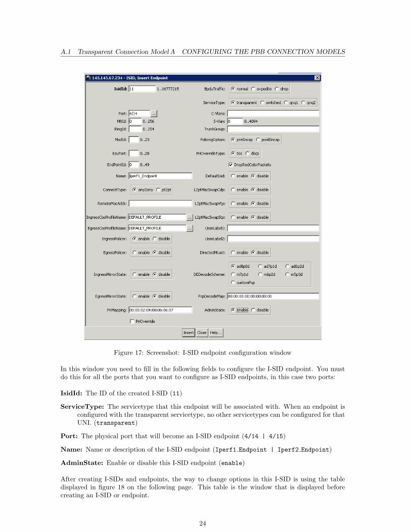
In this window you need to fill in the following fields to configure the I-SID endpoint. You mustdo this for all the ports that you want to configure as I-SID endpoints, in this case two ports:
IsidId: The ID of the created I-SID (11)
ServiceType: The servicetype that this endpoint will be associated with. When an endpoint isconfigured with the transparent servicetype, no other servicetypes can be configured for thatUNI. (transparent)
Port: The physical port that will become an I-SID endpoint (4/14 | 4/15)
Name: Name or description of the I-SID endpoint (Iperf1 Endpoint | Iperf2 Endpoint)
AdminState: Enable or disable this I-SID endpoint (enable)
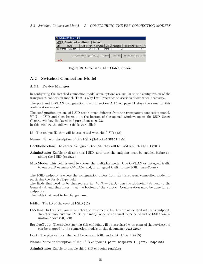
After creating I-SIDs and endpoints, the way to change options in this I-SID is using the tabledisplayed in figure 18 on the following page. This table is the window that is displayed beforecreating an I-SID or endpoint.
24
A.2 Switched Connection Model A CONFIGURING THE PBB CONNECTION MODELS
Figure 18: Screenshot: I-SID table window
A.2 Switched Connection Model
A.2.1 Device Manager
In configuring the switched connection model some options are similar to the configuration of thetransparent connection model. That is why I will reference to sections above when necessary.
The port and B-VLAN configuration given in section A.1.1 on page 21 stays the same for thisconfiguration model.
The configuration options of I-SID aren’t much different from the transparent connection model.VPN → ISID and then Insert... at the bottom of the opened window, opens the ISID, InsertGeneral window displayed in figure 16 on page 23.In this window the following fields were filled:
Id: The unique ID that will be associated with this I-SID (12)
Name: Name or description of this I-SID (Switched RP802.1ah)
BackboneVlan: The earlier configured B-VLAN that will be used with this I-SID (200)
AdminState: Enable or disable this I-SID, note that the endpoint must be enabled before en-abling the I-SID (enable)
MuxMode: This field is used to choose the multiplex mode. One C-VLAN or untagged trafficto one I-SID or many C-VLANs and/or untagged traffic to one I-SID (manyToone)
The I-SID endpoint is where the configuration differs from the transparent connection model, inparticular the ServiceType field.The fields that need to be changed are in: VPN → ISID, then the Endpoint tab next to theGeneral tab and then Insert... at the bottom of the window. Configuration must be done for allendpoints.The fields that need to be changed are:
IsidId: The ID of the created I-SID (12)
C-Vlans: In this field you must enter the customer VIDs that are associated with this endpoint.To enter more customer VIDs, the manyToone option must be selected in the I-SID config-uration above (20, 30).
ServiceType: The servicetype that this endpoint will be associated with, some of the servicetypescan be mapped to the connection models in this document (switched)
Port: The physical port that will become an I-SID endpoint (4/14 | 4/15)
Name: Name or description of the I-SID endpoint (Iperf1 Endpoint | Iperf2 Endpoint)
AdminState: Enable or disable this I-SID endpoint (enable)
25
A.3 Retagging Connection Model B TESTING
A.3 Retagging Connection Model
A.3.1 Device Manager
The configuration for retagging is greatly similar to the configuration of the switched connectionmodel.There are only two differences:
I-SID configuration The MuxMode in the I-SID configuration must be oneToone. The reasonfor this is that you are changing the tags of one customer VLAN to tags of another customerVLAN.
I-SID endpoint configuration The C-Vlans field in the endpoints must point to the C-VID ofthat customer.E.g., Customer-1 VID A on endpoint 1 wants to communicate with customer-2 VID B onendpoint 2, the I-SID endpoint entry for customer-1 must have VID A in the C-Vlans fieldand customer-2 must have VID B in the C-Vlans field of his own entry.
A.4 Q-in-Q Connection Model
A.4.1 Device Manager
Before I give the Q-in-Q configuration options I want to say that these configurations are untested.The reason for this is that I didn’t have enough time to get the correct equipment to generateQ-in-Q traffic.
The Q-in-Q model that associates based only on the S-VID can be configured in the same manneras the switched connection model but with a few changes:
I-SID configuration The MuxMode must be oneToone.
I-SID endpoint configuration The ServiceType must be changed to qnq1. Also the S-VLANID must be entered in the S-Vlan field.The C-Vlans field can stay empty because the BEB associates only based on the S-VID.
Port configuration The Q-in-Q ethertype can be changed if necessary in the Interface tab. Thestandard ethertype in the port configuration is 0x8020, while the official ethertype for Q-in-Qis 0x88a8. I don’t know if this option influences the I-SID configuration because I could nottest it.
The model based on S-VID and C-VID association, needs two adjustments in the configurationwith the configuration above as basis:
I-SID configuration The ServiceType must be changed to qnq2 to support classification basedon S-VID and C-VID.The C-VID must be entered in the C-Vlans field, if it wasn’t already entered.
B Testing
To ensure that the PBB switch was configured correctly I did a ping between the two servers.
The first test was untagged traffic in the Transparent Connection Model. This test needed noextra configurations besides giving eth2 of both servers an IP-address.
26
B TESTING
The second test was tagged traffic in the Transparent- and Switched Connection Model. This testneeded extra configuration on the servers to make it possible for the servers to generate VLAN-tagged traffic, VLANs can be configured with the vconfig program.The commands used to configure VLANs on the servers were:
#Create a VLAN sub interface on the eth2 interfacesudo /sbin/vconfig add <eth-interface> <VLAN ID number>
#Bring VLAN 20 on eth2 up and gives it an IP-addresssudo /sbin/ifconfig <name sub interface> <ip-address> broadcast <broadcast-ip>netmask <netmask>
#<name sub interface> = <eth-interface>.<VLAN ID number>
After this was done for both sides they could ping each other in Transparent Connection Modelwithout any extra switch configurations and in Switched Connection Model after the VLAN-IDwas given in the C-Vlans field explained A.2 on page 25.
When I was experimenting with different VLANs on the servers, a peculiar problem arose.While I was sending ping requests from iperf1 to iperf2, I brought the VLAN interface of iperf2down, but there was no change meaning pinging didn’t halt. After trying different setups withVLANs the problem persisted, I then did a tcpdump to see if there was any difference between thepackets sent and received while pinging.When I reviewed the captured packets I saw that the Ethernet Destination Address and SourceAddress of the packets stayed the same. This would mean that the eth-interface does not lookat the IP-address, but only the MAC-address of the VLAN, before replying to the ping. Anotherpossibility is that the sub interface does not really go down when the following command is given:
sudo /sbin/ifconfig <name sub interface> down
I solved this problem by changing the hardware address of the sub interface:
sudo /sbin/ifconfig <name sub interface> hw ether <MAC-address>
After doing this, pinging between the servers behaved accordingly when I brought a VLAN-interface down.
When I reached testing of the Retagging Connection Model I configured different VLANs on eachserver and followed the configuration steps given in A.3 on the preceding page, pinging worked.
One more step that was needed to make it possible to ping between the servers in the RetaggingConnection Model was the IP configuration, this can be done in two ways:
1. Static IP Route between the servers.sudo /sbin/route add <IP-address of the other endpoint (server)>/32 <name subinterface>
2. Change the IP-address of the sub interface on the server, in addresses in the same broadcastdomain.sudo /sbin/ifconfig <name sub interface> <ip-address> broadcast <broadcast-ip>netmask <netmask>
Now I wanted to see the VLAN-tagged frames so that I could make sure that retagging was beingdone. I thought that if I used tcpdump on eth2 and not the VLAN sub interface I would get theVLAN-tagged frames. This was an incorrect conclusion of mine.The solution to this problem was that I needed to completely remove all VLAN sub interfacesbefore I could capture the tagged frames. You don’t receive ping replies anymore but you can see
27
B TESTING
the tagged frames.I would think the reason for this is that the process that is used by vconfig to direct frames to thecorrect VLAN, removes the VLAN-tag before it can be captured by tcpdump.To completely remove a VLAN sub interface the following command must be given for all subinterfaces:
sudo /sbin/vconfig rem <name sub interface>
Below I give hex of two frames, one from iperf1 VLAN 10 to iperf2 VLAN 40 and vice versa.This is proof that retagging works but can also be used as proof that tagged traffic is forwardedthrough the PBBN.
Hex dump of iperf1 VLAN 10:
0004 23d2 9b4e 0004 23d2 9b6c <8100> [000a]0800 4500 0054 0000 4000 4001 e285 ac100002 ac10 0001 0800 0098 b455 00a7 e5202d49 38fe 0c00 0809 0a0b 0c0d 0e0f 10111213 1415 1617 1819 1a1b 1c1d 1e1f 20212223 2425 2627 2829 2a2b 2c2d 2e2f 3031
The hex value between <> is the ethertype for IEEE 802.1Q (VLAN tagging).The last twelve bits of the hex between [ ] give the ID of this VLAN. The twelve bits are000000001010, meaning VID 10.
Hex dump of iperf2 VLAN 40:
0004 23d2 9b6c 0004 23d2 9b4e <8100> [0028]0800 4500 0054 0000 4000 4001 e285 ac100001 ac10 0002 0800 e428 c97a 1841 77a12a49 a32d 0200 0809 0a0b 0c0d 0e0f 10111213 1415 1617 1819 1a1b 1c1d 1e1f 20212223 2425 2627 2829 2a2b 2c2d 2e2f 3031
The hex value between <> is the ethertype for IEEE 802.1Q (VLAN tagging).The last twelve bits of the hex between [ ] give the ID of this VLAN. The twelve bits are000000101000, meaning VID 40.
28