Embed Size (px)
Citation preview

Danfoss DrivesVLT® Product Catalogue
T H E R E A L D R I V E

This unique modular concept is also the basis for a highly automated quality manufacturing process, where Danfoss Drives takes responsibility for every element – starting with the essential semi conductor power modules. Power Modules are produc- ed in Danfoss Silicon Power in Schleswig, Germany. High quality standards and efficient manufactur-ing facilities makes Danfoss Silicon Power modules in great demand within industries that provide highly automated power-applications like the automotive sector.
When it comes to quality, delivery and cooperation, Danfoss makes high demands on their suppliers – both from inside and outside of the group.
Due to an unsurpassed level of auto- mation Danfoss can produce a cus-tomer configured drive from 1.6 mil-lion possible configuration in a manufacturing time of two hours. The unique string code that fully defines the drive can easily be obtained throughout the world by use of the internet; it determines the configura-tion of all elements of the drive, both electronics and hardware. Once this unique configuration is passed to the production departments the manu-facturing process can begin, testing is carried out at all stages of the process and begins with optical checks of the PCBs to ensure that components are inserted correctly, once the PCBs are fully assembled they all must pass an automatic in circuit test. After as-sembly is complete all drives are fully tested on motor loads.
Two thousand employees headed from Graasten in Denmark develop,manufacture, sell and service elec-tronic motor controls in more than one hundred countries.
Manufacturing takes place in USA – Especially the high power products –and in Asia, but the major production takes place in the plants in Graasten, where half of the staff are employed. Danfoss Bauer geared motors are ma- nufactured in Esslingen, Germany.
The success of Danfoss is due to the strong combination of technology and application knowledge through-out the world combined with a highly sophisticated set-up of product devel- opment, supply chain, logistics and on site presence anywhere on the globe.
Our customers are closely involved during every stage of design and development, specifying their needs in terms of features and user inter-face. Danfoss Drives dedicates itself to every step in every process until the customer has the drive in hand.
The developers at Danfoss Drives have fully adopted modular principles in development as well as design, pro-duction and configuration. Each func- tion is developed in parallel on dedi- cated technology platforms and interfaces between the elements are carefully defined. This allows develop-ment to take place for each element in parallel, reducing time to market and ensuring that customers always enjoy the benefits of recently deve-loped features.
During the drives manufacturing cycle the correct manual is being printed and made avaiable for pack-ing. By the use of this process we en-sure that not only the correct lang-uage but the very latest version of the manual is always produced and shipped with the correct drive. Just in time delivery is a reality.
Once the drive is shipped one of more than 60 local Danfoss sales companies can ensure that the drive is correctly installed and commissioned. Once the equipment is commissioned the level of service the customer requires can be defined in an agreement with the customer according to his specific needs. At every step of the way, from developement of new technologies and features, the mass production of highly customised products, to installation and service Danfoss Drives has only the customer in mind.
The leading provider of Drives
2

3
VLT® 2800 SeriesAn extremely compact series of drives prepared for side-by-side mounting and developed specifically for the low power market.
page 4
VLT® Decentral FCD 300The VLT® Decentral FCD 300 is a complete frequency converter designed for decentral mounting.
page 18
VLT® Decentral Motor Starter DMS 300The DMS 300 is the decentral motor start-er with integrated soft-start functionality for decentral drive solutions where no variable speed is required.
page 20
VLT® Soft Starter MCD 100The VLT® Soft Starter MCD 100 provides soft start features for low power applica-tions 1.1 - 11 kW.
page 22
VLT® Compact Starter MCD 200The MCD 200 is a compact and cost effec-tive soft starter range for applications where direct-on-line starting is undesirable. MCD 200 is due to its size and functionality a good alternative to other reduced voltage starting methods such as start/delta starters. page 24
VLT® Soft Starter MCD 3000The MCD 3000 is a total motor starter providing all the best in soft starter func-tionality. It offers high end functionality whatever it is for starting, stopping or protection of motor or application.
page 26
VLT® Harmonic Filter AHF 005/010Connecting the AHF 005/010 harmonic filter in front of a Danfoss frequency converter is an easy and effective way to reduce harmonic distortion.
page 28
VLT® AutomationDrive The VLT® AutomationDrive represents a single drive concept to control the en-tire range of operations from standard to servo on any machine or production line.
page 6
VLT® DriveMotor FCM 300The VLT ® FCM 300 Series is a very compact alternative to the traditional solution with a VLT® frequency converter and motor as separate units.
page 30
VLT® 5000 FluxThe VLT® 5000 Flux is an extension of the existing VLT® 5000 series. Full torque control also under acceleration as well as very accurate speed control even at low speed or standstill can now be obtained.
page 10
VLT® 5000The perfect match for an abundance of industrial applications.
page 8
VLT® 6000 HVACThe VLT® 6000 HVAC is fully dedicatedto the optimum operation of HVACapplications. It offers energy savingsand user-friendliness, and all functionsare built in.
page 14
VLT® 8000 AQUAThe VLT® 8000 AQUA is designed for the water and waste water market.
page 16
VLT® HVAC DriveThe VLT ® HVAC Drive integrates and communicates seamlessly with all HVAC devices, mastered by Building Manage-ment Systems or as stand-alone unit.
page 12

4
VLT® 2800 SeriesThe VLT® 2800 series are among the smallest multi purpose drives in the market. Designed for space saving side-by-side mounting. Choose to have it with built in Motor Coils, RFI filter, LC+1B filters e.g.
The VLT® 2800 was designed as an ad- vanced and versatile drive, yet easy to operate. Quick menu Includes all parameters basically needed for commissioning the drive. Offers fast installation and service.
Precise stopConventional units rely on a periodic scan of the Digital Inputs, which initi-ates the Stop command. This can re-sult in uneven delays while the Drive scans all the other parts of the pro-gram taking up to perhaps 10 ms. This is a disadvantage in typical packaging applications. For a conveyor operat-ing at a speed of 1 meter/second, that gives a deviation of ±10 mm. In the VLT® 2800, the Stop command is an Interrupt rather than part of the scan. The repeating precision is improved. The deviation is only ±1mm in the example used above.
Counter Precise StopAfter the start signal is received, the VLT® 2800 operates until the user pro- grammed number of pulses is seen at terminal 33. A Stop signal is generat- ed and the normal stop ramp is used. The counter stop signal is then re- armed and ready again for a new start command. The pulse input is de-signed to handle 24 V push-pull pulses from an encoder with 1024 ppr. The maximum pulse rate is 67,600 Hz.
Product safety• 100 % short-circuit proof• 100 % earth fault protection• Mains transient protection• Switching on input• Switching on output• Galvanic isolation• Designed according to EN50178
Flexible mounting
1800 RPM
900 RPMSpeed
CompensationDelay

5
Mains supply (L1, L2, L3): Supply voltage VLT 2803-2815 220-240 V (N, L1) ......1 x 220/230/240 V ±10%Supply voltage VLSpec txtT 2803-2840 200-240 V .................................................................................. 3 x 200/208/220/230/240 V ±10%Supply voltage VLT 2805-2882 380-480 V .. 3 x 380/400/415/440/480 V ±10%Supply frequency .................................................................................50/60 Hz ± 3 HzMax. imbalance on supply voltage ................... ± 2.0% of rated supply voltageTrue Power Factor (λ) ..................................................... 0.90 nominal at rated loadDisplacement Power Factor (cosф) ............................................near unity (> 0.98)Number of connections at supply input L1, L2, L3 ......................... 2 times/min.Max. short-circuit value. ................................................................................ 100,000 A
Output data (U, V, W):Output voltage. ............................................................... 0 - 100% of supply voltageOutput frequency ................................................................0.2 - 132 Hz, 1 - 1000 HzRated motor voltage, 200-240 V units .......................... 200/208/220/230/240 VRated motor voltage, 380-480 V units .................380/400/415/440/460/480 VRated motor frequency .................................................................................... 50/60 HzSwitching on output. ..................................................................................... UnlimitedRamp times ...............................................................................................0.02 - 3600 sec.
Torque characteristics:Starting torque Constant torque) .....................................................160%in 1 min.*Starting torque (Variable torque) ...................................................160% in 1 min.*Starting torque (parameter 119 High starting torque ) ......180% for 0.5 sec.*Overload torque (Constant torque) ................................................................. 160%*Overload torque (Variable torque) ................................................................... 160%**Percentage relates to frequency converter’s nominal current.
Control card, digital inputs:Number of programmable digital inputs ..................................................................5Terminal number ................................................................................. 18, 19, 27, 29, 33Voltage level. .............................................................0 - 24 V DC (PNP positive logic)Voltage level, logic ’0’ ........................................................................................ < 5 V DCVoltage level, logic ’1’ ......................................................................................> 10 V DCMaximum voltage on input ..............................................................................28 V DCInput resistance, Ri (terminals 18, 19, 27, 29) ....................................approx. 4 kΩInput resistance, Ri (terminal 33) ...........................................................approx. 2 kΩAll digital inputs are galvanically isolated from the supply voltage (PELV) and other high-voltage terminals.
Control card, analog inputs:Number of analog voltage inputs .......................................................................1 pcs.Terminal number ............................................................................................................. 53Voltage level. .............................................................................. 0 - 10 V DC (scaleable)Input resistance, Ri . ................................................................................. approx. 10 kΩMax. voltage ...................................................................................................................20 VNumber of analog current inputs ........................................................................1 pcs.Terminal number ............................................................................................................ 60Current level ..............................................................................0/4 - 20 mA (scaleable)Input resistance, Ri ................................................................................. approx. 300 ΩMax. current .............................................................................................................. 30 mAResolution for analog inputs ............................................................................... . 10 bitAccuracy of analog inputs ............................................. Max. error 1% of full scaleScan interval. ...................................................................................................... 13.3 msecThe analog inputs are galvanically isolated from the supply voltage (PELV) and other high-voltage terminals.
Control card, pulse inputs:Number of programmable pulse inputs ....................................................................1Terminal number ............................................................................................................. 33Max. frequency at terminal 33 .................................................67.6 kHz (Push-pull)Max. frequency at terminal 33 ............................................ 5 kHz (open collector)Min. frequency at terminal 33 .............................................................................. 4 HzVoltage level. ............................................................0 - 24 V DC (PNP positive logic)Voltage level, logic ’0’ ........................................................................................ < 5 V DCVoltage level, logic ’1’ ..................................................................................... > 10 V DCMaximum voltage on input ...............................................................................28 V DCInput resistance, Ri ......................................................................................approx. 2 kΩScan interval ....................................................................................................... 13.3 msecResolution ....................................................................................................................10 bitAccuracy (100 Hz- 1 kHz) terminal 33 ................... Max. error: 0.5% of full scaleAccuracy (1 kHz - 67.6 kHz) terminal 33 ................Max. error: 0.1% of full scaleThe pulse input (terminal 33) is galvanically isolated from the supply voltage (PELV) and other high-voltage terminals.
SpecificationsControl card, digital/frequency output:Number of programmable digital/pulse outputs ........................................ 1 pcs.Terminal number ............................................................................................................. 46Voltage level at digital/frequency output .........................0 - 24 V DC (O.C PNP)Max. output current at digital/frequency output ....................................... 25 mA.Max. load at digital/frequency output ............................................................... 1 kΩMax. capacity at frequency output ..................................................................... 10 nFMinimum output frequency at frequency output ....................................... 16 HzMaximum output frequency at frequency output ......................................10 kHzAccuracy on frequency output ................................Max. error: 0.2 % of full scaleResolution on frequency output ........................................................................ 10 bitThe digital output is galvanically isolated from the supply voltage (PELV) and other high-voltage terminals.
Control card, analog output:Number of programmable analog outputs . ........................................................... 1Terminal number ............................................................................................................. 42Current range at analog output ............................................................... 0/4 - 20 mAMax. load to common at analog output .......................................................... 500 ΩAccuracy on analog output ......................................Max. error: 1.5 % of full scaleResolution on analog output ................................................................................10 bitThe analog output is galvanically isolated from the supply voltage (PELV) and other high-voltage terminals.
Control card, 24 V DC output:Terminal number ............................................................................................................. 12Max. load . ................................................................................................................130 mA
The 24 V DC supply is galvanically isolated from the supply voltage (PELV) , but has the same potential as the analogue and digital inputs and outputs.
Control card, 10 V DC output:Terminal number ............................................................................................................. 50Output voltage .............................................................................................10.5 V ±0.5 VMax. load .................................................................................................................... 15 mAThe 10 V DC supply is galvanically isolated from the supply voltage (PELV) and other high-voltage terminals.
Control card, RS 485 serial communication:Terminal number ........................................................... 68 (TX+, RX+), 69 (TX-, RX-)Terminal number 67 .................................................................................................. + 5 VTerminal number 70 ................................... Common for terminals 67, 68 and 69Full galvanic isolation.
Relay outputs:Number of programmable relay outputs ..................................................................1Terminal number, control card ............................................1-3 (break), 1-2 (make)Max. terminal load (AC) on 1-3, 1-2, control card ........................... 240 V AC, 2 AMin. terminal load on 1-3, 1-2, control card ..... 24 V DC 10 mA, 24 V AC 100 mAThe relay contact is separated from the rest of the circuit by strengthened isolation.
Cable lengths and cross sections:Max. motor cable length, screened/armoured cable .................................... 40 mMax. motor cable length, unscreened/unarmoured cable ......................... 75 mMax. motor cable length, screened/armoured cable and motor coil. ..100 mMax. motor cable length, unscreened/unarmoured cable and motor coil ...............................................................................................200 mMax. motor cable length, screened/armoured cable and RFI/1B filter ............................................................................................ 200 V, 100 mMax. motor cable length, screened/armoured cable and RFI/1B or RFI 1B/LC filter ..................................................................... 400 V, 25 mMax. cross section to control wires, rigid wire ................................................................1.5 mm2/16 AWG (2 x 0.75 mm2)Max. cross section to control cables, flexible cable ..................1 mm2/18 AWGMax. cross section to control cables, cable with enclosed core ............................................................................ 0.5 mm2/20 AWGWhen complying with EN 55011 1A and EN 55011 1B the motor cable must in certain instances be reduced.

6
VLT® AutomationDrive
One-Drive conceptOne drive concept covering the whole production or machine is a major benefit in commissioning, operating and maintaining the equipment. The make through modular design makes upgrade easy as well as adaptation of future features. On-board manuals makes operation easy and the built in Smart Logic Control allows for basic programming covering most com-mon PLC functions.
Plug and playYou don’t have to disconnect wires in the cage clamps to disconnect the VLT® AutomationDrive. Just unplug the cage clamp instead.
Pluggable optionsThe bus option ready to plug in underneath the front panel. It can be turned upside down if youprefer the cable to enter from the top.
USB pluggableThe VLT ® AutomationDrive can be remotely commissioned and monitor-ed through a USB plugable cable or bus communication. Special software is available: Wizards, Data transfer tool, VLT® Set-up Software MCT 10.
Remote commissioningLocal control of the VLT® Automation-Drive is done by a local control panel. This is plugged in directly or con-nected through a cable. The control panel can also be connected directly to a PC for service or commissioning.
The VLT® AutomationDrive FC 300 is extremely configurable and runs any motor in any application and any machine for manufacturing. Specify your requirements and have your drives tailor-made within a couple of hours – for the cost of mass produced stockware.
Range: 0.25 – 37 kW (200 – 240 V)0.37 – 800 kW (380 – 500 V)37 – 1000 kW (600 V)

7
Mains supply (L1, L2, L3):Supply voltage ......................................................................................200-240 V ±10%Supply voltage .............................. FC 301: 380-480 V / FC 302: 380-500 V ±10%Supply voltage ..................................................................... FC 302: 525-600 V ±10%Supply frequency .............................................................................................. 50/60 HzMax. imbalance between mains phases. ....... ± 3.0 % of rated supply voltageTrue Power Factor (λ) ..................................................... 0.92 nominal at rated loadDisplacement Power Factor (cosф) near unity. .......................................... (> 0.98)Switching on input supply L1, L2, L3 (power-ups) .....maximum 2 times/min.Environment according to EN60664-1overvoltage category 111/pollution degree 2.
The unit is suitable for use on a circuit capable of delivering not more than 100.000 RMS symmetrical Amperes, 240/500/600 V maximum.
Digital inputs:Programmable digital inputs ...................................... FC 301: 4 (5) / FC 302: 4 (6)Terminal number .......................................................18, 19, 27 1), 291), 32, 33, 372)Logic ...............................................................................................................PNP or NPN3)Voltage level ..................................................................................................... 0 - 24 V DCVoltage level, logic’0’ PNP ................................................................................ < 5 V DCVoltage level, logic’1’ PNP ..............................................................................> 10 V DCVoltage level, logic ’0’ NPN3) .........................................................................> 19 V DCVoltage level, logic ’1’ NPN3) .........................................................................< 14 V DCMaximum voltage on input ...............................................................................28 V DCInput resistance, Ri ......................................................................................approx. 4 kΩ
All digital inputs are galvanically isolated from the supply voltage (PELV) and other high-voltage terminals. 1) Terminals 27 and 29 can also be programmed as output.2) Terminal 37 is only available in FC 302. It can only be used as “safe stop” input. Terminal 37 is suitable for category 3 installations according to EN 954-1 (safe stop according to category 0 EN 60204-1).3) Exception: Terminal 37 is fixed PNP logic.
Analogue inputs:Number of analogue inputs ..........................................................................................2Terminal number ...................................................................................................... 53, 54Modes ...................................................................................................Voltage or currentMode select .................................................................. Switch S201 and switch S202Voltage mode ...................................................Switch S201/switch S202 = OFF (U)Voltage level ........................ FC 301: 0 to + 10 / FC 302: -10 to +10 V (scaleable)Input resistance, Ri .................................................................................. approx. 10 kΩMax. voltage ...............................................................................................................± 20 VCurrent mode ...................................................... Switch S201/switch S202 = ON (I)Current level .......................................................................... 0/4 to 20 mA (scaleable)Input resistance, Ri ................................................................................... approx. 200 ΩMax. current .............................................................................................................. 30 mAResolution for analogue inputs . ..........................................................10 bit (+ sign)Accuracy of analogue inputs .....................................Max. error 0.5% of full scaleBandwidth .................................................................. FC 301: 20 Hz / FC 302: 100 Hz
The analogue inputs are galvanically isolated from the supply voltage (PELV)and other high-voltage terminals.
SpecificationsPulse/encoder inputs:Programmable pulse/encoder inputs ....................................................................2/1Terminal number pulse/encoder. ......................................... 29, 331) / 18, 32, 332)Max. frequency at terminal 18, 29, 32, 33 ................110 kHz (Push-pull driven)Max. frequency at terminal 18, 29, 32, 33 ....................... 5 kHz (open collector)Min. frequency at terminal 18, 29, 32, 33. ............................................................4 HzVoltage level .................................................................... see section on Digital inputMaximum voltage on input ...............................................................................28 V DCInput resistance, Ri ......................................................................................approx. 4 kΩPulse input accuracy (0.1 - 1 kHz) ........................... Max. error: 0.1% of full scaleEncoder input accuracy (1 - 110 kHz) ................ Max. error: 0.05 % of full scale32 (A), 33 (B) and 18 (Z)
The pulse and encoder inputs (terminals 18, 29, 32, 33) are galvanically isolated from the supply voltage (PELV) and other high-voltage terminals. 1) Pulse inputs are 29 and 332) Encoder inputs: 18 = Z, 32 = A, and 33 = B
Digital output:Programmable digital/pulse outputs .........................................................................2Terminal number ................................................................................................. 27, 29 1)Voltage level at digital/frequency output ................................................... 0 - 24 VMax. load at frequency output ............................................................................... 1 kΩMax. capacitive load at frequency output ....................................................... 10 nFMinimum output frequency at frequency output ..........................................0 HzMaximum output frequency at frequency output .....................................32 kHzAccuracy of frequency output . ...............................Max. error: 0.1 % of full scaleResolution of frequency outputs .........................................................................12 bit
1) Terminal 27 and 29 can also be programmed as input.The digital output is galvanically isolated from the supply voltage (PELV) and other high-voltage terminals.
Relay outputs:Programmable relay outputs .................................................. FC 301: 1 / FC 302: 2Terminal number, power card. ..................................1-3 (break), 1-2 (make), 4-6 (break), 4-5 (make)Max. terminal load on 1-3 (break), 1-2 (make), 4-6 (break) power card ............................................................................. 240 V AC, 2 AMax. terminal load (AC) on 4-5 (make) power card ....................... 400 V AC, 2 AMin. terminal load on 1-3 (break), 1-2 (make), 4-6 (break), 4-5 (make) power card ................. 24 V DC 10 mA, 24 V AC 100 mAEnvironment according to EN 60664-1 overvoltage category III/pollution degree 2.
The relay contacts are galvanically isolated from the rest of the circuit by reinforced isolation (SELV).

8
VLT® 5000 SeriesThe VLT® Series 5000 available in the power range from 0.75 kW-500 kW suits all industrial applications.
Benefits:• Saves space and energy – the com pact size saves valuable space. The perfect speed matching to actual load reduces your energy costs.• Easy to commission and use - If you know one drive you also know the others and a Quick Menu guides you easily through the little pro- gramming work left for you to make the drive perfect for the job in your plant.• Multi-Setup – The drive has four independent setups.• Enclosures IP20, IP54, IP00, Optional coating providing extra protection for aggressive environments. Com- pliance with international standards Built-in RFI filters available for the entire product range complying with EN55011, class 1A and 1B.
Complies also with IEC 61000-3-2 and 61000-3-4 as well as VDE 0160 as regards levels of harmonic suppres-sion. That reduces the dimensions of cables substantially.
Product range: 200-690V: 0.75 kW - 500 kW
SyncPosTo complement the comprehensive functionality of VLT® frequency converters Danfoss Drives offers dedicated engineering solutions for your application. Based on the high flexibility of the Programmable SyncPos motion controller we tailor solutions to fit perfectly applicationrequirements.
Marine approvals• DNV – Det Norske Veritas• GL – Germanisher Lloyd• LRS – Lloyds Register of Shipping• BV – Bureau Veritas• ABS – American Bureau of Shipping• RINA – Registro Italiano Navale
Fieldbus optionsVLT® 5000 have dedicated fieldbus options for: • Profibus DP V0• Profibus DP V1• DeviceNet• Interbus• Modbus+• LonWorks

9
Mains supply (L1, L2, L3):Supply voltage 200-240 V units .................. 3 x 200/208/220/230/240 V ±10%Supply voltage 380-500 V units .......... 3 x 380/400/415/440/460/500 V ±10%Supply voltage 525-600 V units .............................3 x 525/550/575/600 V ±10%Supply frequency:Max imbalance of supply voltage: ................................................. 48-62 Hz +/- 1%True Power factor (λ) .......................................................0.90 nominal at rated loadDisplacement Power Factor (cos ф) ........................................... near unity (>0.98)No. of switchings on supply input L1, L2, L3 ...................... approx. 1 time/min.
VLT output data (U, V, W):Output voltage ................................................................... 0-100% of supply voltageOutput frequency ........................................................................................... 0 - 1000 HzRated motor voltage, 200-240 V units ...........................200/208/220/230/240 VRated motor voltage, 380-500 V units .........380/400/415/440/460/480/500 VRated motor voltage, 525-600 V units ............................................ 525/550/575 VRated motor frequency ................................................................................ UnlimitedRamp times ............................................................................................... . 0.05-3600 sec.
Control card, digital inputs:Number of programmable digital inputs ................................................................ 8Terminal nos. .................................................................... 16, 17, 18, 19, 27, 29, 32, 33Voltage level .............................................................. 0-24 V DC (PNP positive logics)Voltage level, logical ’0’ ..................................................................................... < 5 V DCVoltage level, logical ’1’ ...................................................................................>10 V DCMaximum voltage on input ..............................................................................28 V DCInput resistance, Ri ...................................................................................................... 2 kΩScanning time per input. . . . . . . ....................................................................... 3 msec.
Reliable galvanic isolation: All digital inputs are galvanically isolated from the supply voltage (PELV). In addition, the digital inputs can be isolated from the other terminals on the control card by connectingan external 24 V DC supply and opening switch 4. VLT 5001-5250, 525-600 V do not meet PELV.
Control card, analogue inputs:No. of programmable analogue voltage inputs/thermistor inputs .................2Terminal nos ............................................................................................................... 53, 54Voltage level ...............................................................................0 - ±10 V DC (scalable)Input resistance, Ri ....................................................................................................10 kΩNo. of programmable analogue current inputs ......................................................1Terminal no. ..................................................................................................................... . 60Current range .......................................................................... 0/4 - ±20 mA (scalable)Input resistance, Ri .................................................................................................. 200 ΩResolution ..................................................................................................... 10 bit + signAccuracy on input ............................................................. Max. error 1% of full scaleScanning time per input. ................................................................................... 3 msec.Terminal no. ground ...................................................................................................... 55
Reliable galvanic isolation: All analogue inputs are galvanically isolated from the supply voltage (PELV)* as well as other inputs and outputs. * VLT 5001-5250, 525-600 V do not meet PELV.
Control card, pulse/encoder input: No. of programmable pulse/encoder inputs ............................................................4Terminal nos ................................................................................................. 17, 29, 32, 33Max. frequency on terminal 17 ............................................................................ 5 kHzMax. frequency on terminals 29, 32, 33 ................20 kHz (PNP open collector)Max. frequency on terminals 29, 32, 33 .................................. 65 kHz (Push-pull)Voltage level .............................................................. 0-24 V DC (PNP positive logics)Voltage level, logical ’0’ ..................................................................................... < 5 V DCVoltage level, logical ’1’. ....................................................................................>10 V DCMaximum voltage on input .............................................................................. 28 V DCInput resistance, Ri ..................................................................................................... 2 kΩScanning time per input .................................................................................... 3 msec.Resolution .......................................................................................................10 bit + signAccuracy (100-1 kHz), terminals 17, 29, 33 ...........Max. error: 0.5% of full scaleAccuracy (1-5 kHz), terminal 17 ................................Max. error: 0.1% of full scaleAccuracy (1-65 kHz), terminals 29, 33 ....................Max. error: 0.1% of full scale
Reliable galvanic isolation: All pulse/encoder inputs are galvanically isolated from the supply voltage (PELV)*. In addition, pulse and encoder inputs can be isolated from the other terminals on the control card by connecting an external 24 V DC supply and opening switch 4. * VLT 5001-5250, 525-600 V do not meet PELV.
SpecificationsControl card, digital/pulse and analogue outputs:No. of programmable digital and analogue outputs. ...........................................2Terminal nos ............................................................................................................... 42, 45Voltage level at digital/pulse output ........................................................0 - 24 V DCMinimum load to ground (terminal 39) at digital/pulse output ............ 600 ΩFrequency ranges (digital output used as pulse output) .....................0-32 kHzCurrent range at analogue output .......................................................... 0/4 - 20 mAMaximum load to ground (terminal 39) at analogue output ................... 500 ΩAccuracy of analogue output ...................................Max. error: 1.5% of full scaleResolution on analogue output ............................................................................. 8 bit
Reliable galvanic isolation: All digital and analogue outputs are galvanically isolated from the supply voltage (PELV)*, as well as other inputs and outputs. * VLT 5001-5250, 525-600 V do not meet PELV.
Control card, 24 V DC supply:Terminal nos ............................................................................................................... 12, 13Max. load (short-circuit protection) ................................................................200 mATerminal nos. ground .............................................................................................. 20, 39
Reliable galvanic isolation: The 24 V DC supply is galvanically isolated from the supply voltage (PELV)*, but has the same potential as the analogue outputs. * VLT 5001-5250, 525-600 V do not meet PELV.
Control card, RS 485 serial communication:Terminal nos ..................................................................... 68 (TX+, RX+), 69 (TX-, RX-)Reliable galvanic isolation: Full galvanic isolation.
Relay outputs:No. of programmable relay outputs. ...........................................................................2Terminal nos., control card ........................................................................... 4-5 (make)Max. terminal load (AC) on 4-5, control card. ........................ 50 V AC, 1 A, 60 VAMax. terminal load (DC) on 4-5, control card ......................75 V DC, 0.1 A, 30 WMax. terminal load (DC) on 4-5, control card for UL/cUL applications ...................................................... 30 V AC, 1 A / 42.5 V DC, 1ATerminal nos., power card .....................................................1-3 (break), 1-2 (make)Max. terminal load (AC) on 1-3, 1-2, power card ...............240 V AC, 2 A, 60 VAMax. terminal load on 1-3, 1-2, power card ........................................ 50 V DC, 2 AMin. terminal load on 1-3, 1-2, power card. ... 24 V DC 10 mA, 24 V AC 100 mA
Brake resistor terminals (only SB, EB, DE and PB units):Terminal nos ............................................................................................................... 81, 82
External 24 Volt DC supply:Terminal nos ............................................................................................................... 35, 36Voltage range ......................................... 24 V DC ±15% (max. 37 V DC for 10 sec.)Max. voltage ripple ................................................................................................ 2 V DCPower consumption ............................ 15 W - 50 W (50 W for start-up, 20 msec.)Min. pre-fuse ............................................................................................................. 6 AmpReliable galvanic isolation: Full galvanic isolation if the external 24 V DC supply is also of the PELV type.
Cable lengths, cross-sections and connectors:Max. motor cable length, screened cable .......................................................150 mMax. motor cable length, unscreened cable ..................................................300 mMax. motor cable length, screened cable VLT 5011 380-500 V . ..............100 mMax. motor cable length, screened cable VLT 5011 525-600 V and VLT 5008, normal overload mode, 525-600 V ......................................... 50 mMax. brake cable length, screened cable .......................................................... 20 mMax. loadsharing cable length, screened cable ................................... 25 m from frequency converter to DC bar.Max. cable cross-section for 24 V external DC supply -VLT 5001-5027 200-240 V; VLT 5001-5102 380-500 V; VLT 5001-5062 525-600V .................................................................. 4 mm2 /10 AWGVLT 5032-5052 200-240 V; VLT 5122-5500 380-500 V; VLT 5075-5250 525-600 V. ............................................................. 2.5 mm2 /12 AWGMax. cross-section for control cables. ....................................... 1.5 mm2 /16 AWGMax. cross-section for serial communication. ....................... 1.5 mm2 /16 AWG
If UL/cUL is to be complied with, cable with temperature class 60/75°C must be used (VLT 5001 - 5062 380 - 500 V, 525 - 600 V and VLT 5001 - 5027 200 - 240V).If UL/cUL is to be complied with, cable with temperature class 75°C must be used (VLT 5072 - 5500 380 - 500 V, VLT 5032 - 5052 200 - 240 V, VLT 5075 - 5250 525 - 600 V).Connectors are for use of both copper and aluminium cables, unless other is specified.

10
VLT® 5000 FluxThe VLT® 5000 Flux is an extension of the VLT® 5000 series.
Full torque control under acceleration as well as very accurate speed control even at low speed or standstill can be obtained.
Flux control is the future technology for high performance drives. It pro- vides excellent dynamics and accu-racy, suited for drives systems with and without feedback.
The VLT® 5000 Flux features automa-tic acquisition of motor equivalent circuit diagram and provides 100% control of flux and torque, taking the system inertia into account.
The VLT® 5000 Flux provides up to 160% torque from 0 to rated speed.
SyncPosSyncPos makes VLT® 5000 Flux highlyprogrammable and provides synchro-nising and positioning
Flux principleThe flux principle provides high shaftperformance (Torque control about 3 ms), excellent synchronizing also at very low speed. Speed accuracy with open loop: +/- 0.5 % (8 rpm) and with closed loop +/0.001 % (0.02 rpm).Flux control provides 180% accelera-tion torque (0.5 sec), 160% holding torque at 0 RPM in 60 sec (closed loop). The accuracy of torque control is: closed loop +/- 10%.
Plug-in terminalsPlug-in terminals for motor and control cables
Shaft
A_phi
11
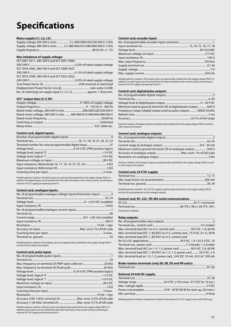
Mains supply (L1, L2, L3):Supply voltage 200-240 V units ................... 3 x 200/208/220/230/240 V ±10%Supply voltage 380-500 V units .......... 3 x 380/400/415/440/460/500 V ±10%Supply frequency ................................................................................. 48-62 Hz +/- 1%
Max imbalance of supply voltage:VLT 5001-5011, 380-500 V and VLT 5001-5006, 200-240 V .................................................................... ±2.0% of rated supply voltageVLT 5016-5062, 380-500 V and VLT 5008-5027, 200-240 V ..................................................................... ±1.5% of rated supply voltageVLT 5072-5500, 380-500 V and VLT 5032-5052, 200-240 V .................................................................... ±3.0% of rated supply voltageTrue Power factor (λ) ......................................................0.90 nominal at rated loadDisplacement Power Factor (cos ф) ........................................... near unity (>0.98)No. of switchings on supply input L1, L2, L3 ......................approx. 1 time/min.
VLT® output data (U, V, W):Output voltage ................................................................... 0-100% of supply voltageOutput frequency ....................................................................... 0 - 132 Hz, 0 - 300 HzRated motor voltage, 200-240 V units ..........................200/208/220/230/240 VRated motor voltage, 380-500 V units ........380/400/415/440/460/480/500 VRated motor frequency. ................................................................................... 50/60 HzSwitching on output ....................................................................................... UnlimitedRamp times ................................................................................................ 0.01-3600 sec.
Control card, digital inputs:Number of programmable digital inputs ................................................................ 8Terminal nos ..................................................................... 16, 17, 18, 19, 27, 29, 32, 33Terminal number for none programmable digital input .................................. 37Voltage level .............................................................. 0-24 V DC (PNP positive logics)Voltage level, logical ’0’ .................................................................................... < 5 V DCVoltage level, logical ’1’ ....................................................................................>10 V DCMaximum voltage on input ...............................................................................28 V DCInput resistance, Ri(terminals 16, 17, 18, 19, 27, 32, 33) ................................ 4 kΩInput resistance, Ri(terminal 29) ............................................................................ 2 kΩScanning time per input ..................................................................................... 3 msec.
Reliable galvanic isolation: All digital inputs are galvanically isolated from the supply voltage (PELV). In addition, the digital inputs can be isolated from the other terminals on the control card by connecting an external 24 V DC supply and opening switch 4.
Control card, analogue inputs:No. of programmable analogue voltage inputs/thermistor inputs ................2Terminal nos .............................................................................................................. 53, 54Voltage level. ..............................................................................0 - ±10 V DC (scalable)Input resistance, Ri. ...................................................................................................10 kΩNo. of programmable analogue current inputs ......................................................1Terminal no. ....................................................................................................................... 60Current range .......................................................................... 0/4 - ±20 mA (scalable)Input resistance, Ri ................................................................................................... 200 ΩResolution .......................................................................................................10 bit + signAccuracy on input. ............................................................ Max. error 1% of full scaleScanning time per input .................................................................................... 3 msec.Terminal no. ground ....................................................................................................... 55
Reliable galvanic isolation: All analogue inputs are galvanically isolated from the supply voltage (PELV) as well as other inputs and outputs.
Control card, pulse input:No. of programmable pulse inputs ..............................................................................1Terminal no ........................................................................................................................ 29Max. frequency on terminal 29 (PNP open collector) ................................20 kHzMax. frequency on terminal 29 (Push-pull) ....................................................65 kHzVoltage level .............................................................. 0-24 V DC (PNP positive logics)Voltage level, logical ’0’ ..................................................................................... < 5 V DCVoltage level, logical ’1’ ....................................................................................>10 V DCMaximum voltage on input ...............................................................................28 V DCInput resistance, Ri ...................................................................................................... 2 kΩScanning time per input .................................................................................... 3 msec.Resolution .......................................................................................................10 bit + signAccuracy (100-1 kHz), terminal 29 ...........................Max. error: 0.5% of full scaleAccuracy (1-65 kHz), terminal 29 .............................Max. error: 0.1% of full scaleReliable galvanic isolation: All pulse inputs are galvanically isolated from the supply voltage (PELV). In addition, pulse inputs can be isolated from the other terminals on the control card by connecting an external 24 V DC supply and opening switch 4.
SpecificationsControl card, encoder input:No. of programmable encoder input connector ....................................................1Input terminal nos ...................................................................... 73, 74, 75, 76, 77, 78Voltage level .....................................................................................................RS 422/485Maximum voltage on input .............................................................................. ±7 V DCInput resistance, Ri ................................................................................................... 140 ΩMax. input frequency ......................................................................................... 250 kHzSupply terminal nos ................................................................................................ 47, 49Supply voltage ................................................................................................................ 5 VMax. supply current ..............................................................................................250 mA
Reliable galvanic isolation: All encoder inputs are galvanically isolated from the supply voltage (PELV). In addition, encoder inputs can be isolated from the other terminals on the control card by connecting an external 24 V DC supply and opening switch 4.
Control card, digital/pulse outputs:No. of programmable digital outputs .........................................................................2Terminal nos. .................................................................................................................6, 46Voltage level at digital/pulse output. ......................................................0 - 24 V DCMinimum load to ground (terminal 39) at digital/pulse output ............ 600 ΩFrequency ranges (digital output used as pulse output) .......... 100HZ-50 kHzRefresh time ..................................................................................................................3 msAccuracy ............................................................................................ ±0.1% of full range
Galvanic isolation: All digital outputs are galvanically isolated from the supply voltage (PELV) as well as other inputs and outputs.
Control card, analogue outputs:No. of programmable digital outputs .........................................................................2Terminal nos ............................................................................................................... 42, 45Current range at analogue output .......................................................... 0/4 - 20 mAMaximum load to ground (terminal 39) at analogue output ................... 500 ΩAccuracy of analogue output ...................................... Max. error: 1% of full scaleResolution on analogue output . ........................................................................... 8 bit
Galvanic isolation: All analogue outputs are galvanically isolated from the supply voltage (PELV) as well as other inputs and outputs.
Control card, 24 V DC supply:Terminal nos ............................................................................................................... 12, 13Max. load (short-circuit protection) ................................................................200 mATerminal nos. ground .............................................................................................. 20, 39
Reliable galvanic isolation: The 24 V DC supply is galvanically isolated from the supply voltage (PELV), but has the same potential as the analogue outputs.
Control card, RS 232 / RS 485 serial communication:RS 232 .......................................................................................................RJ-11 connectorTerminal nos ..................................................................... 68 (TX+, RX+), 69 (TX-, RX-)Full galvanic isolation.
Relay outputs:No. of programmable relay outputs. ...........................................................................2Terminal nos., control card ........................................................................... 4-5 (make)Max. terminal load (AC) on 4-5, control card ......................... 50 V AC, 1 A, 60 VAMax. terminal load (DC-1, IEC847) on 4-5, control card ...75 V DC, 0.1 A, 30 WMax. terminal load (DC-1, IEC947) on 4-5, control card for UL/cUL applications ................................................ 30 V AC, 1 A / 42.5 V DC, 1ATerminal nos., power card. ....................................................1-3 (break), 1-2 (make)Max. terminal load (AC) on 1-3, 1-2, power card . ................ 40 V AC, 2 A, 60 VAMax. terminal load (DC-1, IEC947) on 1-3, 1-2, power card .......... 50 V DC, 2 AMin. terminal load on 1-3, 1-2, power card. . 24 V DC 10 mA, 24 V AC 100 mA
Brake resistor terminals (only SB, EB, DE and PB units):Terminal nos. ............................................................................................................. 81, 82
External 24 Volt DC supply:Terminal nos ............................................................................................................... 35, 36Voltage range ......................................... 24 V DC ±15% (max. 37 V DC for 10 sec.)Max. voltage ripple ................................................................................................. 2 V DCPower consumption ............................ 15 W - 50 W (50 W for start-up, 20 msec.)Min. pre-fuse ............................................................................................................. 6 Amp
Reliable galvanic isolation: Full galvanic isolation if the external 24 V DC supply is also of the PELV type.

The VLT ® HVAC Drive integrates and communicates seamlessly with all HVAC devices, mastered by Building Management Systems or as stand-alone unit. HVAC-specific features makes it economical, flexible and user-friendly and makes HVAC operation child’s play.
Lowest cost of ownershipThe modular concept allovs you to pay only for features you need and to customise your solutions and mini-mise system costs. The HVAC Drive is maintenance free, compact and easily mounted inside a HVAC unit or panel. Advanced, adaptable drive techno-logy in the HVAC Drive generates significant energy savings while ensuring perfect comfort levels.
• Built-in real time clock• Smart Logic Controller • 4 auto-tuned PID controllers• Easy to use menu structure• Integrates with all BMS protocols • Graphical display• Optional mains disconnect switch• Automatic Energy Optimisation • Energy monitoring
VLT® HVAC Drive
Dedicated pump features
• Pump Cascade Controller• Sleep Mode• Sensorless Pressure/Flow Control• Dry Pump Protection• Continuous pumping, also at overload• End of Curve monitoring• Flow compensation at setpoint
Dedicated fan features
• Broken belt detection• Resonance Monitoring• Fire Override mode• Stairwell Pressurization• Automated skip frequencies• Supply and return flow balancing• Very fast flying start• Conversion of feedback signal
Power range: 200-240V: 1.1 kW – 45 kW380-480V: 1.1 kW – 400 kW525-600V: 1.1 kW – 400 kW
Dedicated compressor features
• Capacity Modulation• Constant torque above 20 Hz• Cascade Controller• 160% break away torque • Set point in temperature or pressure conversion• Reduced number of starts and stops
12

Mains supply (L1, L2, L3): Supply voltage: ....................................................................................200-240 V ±10%Supply voltage: ....................................................................................380-500 V ±10%Supply voltage: ....................................................................................525-600 V ±10%Supply frequency .............................................................................................. 50/60 HzDisplacement Power Factor (cos φ) near unity .......................................... (> 0.98)Switching on input supply L1, L2, L3 .............................................. 1-2 times/min.
Output data (U, V, W):Output voltage ................................................................... 0-100% of supply voltageSwitching on output ....................................................................................... UnlimitedRamp times ....................................................................................................1 - 3600 sec.Closed loop ...........................................................................................................0-132 Hz
Digital inputs:Programmable digital inputs, FC 102: .....................................................................6*Logic ..................................................................................................................PNP or NPNVoltage level ......................................................................................................0 - 24 VDC* 2 can be used as digital outs
Analog inputs:Analog inputs .....................................................................................................................2Modes ..................................................................................................Voltage or currentVoltage level: ...........................................................................-10 to +10 V (scaleable)Current level .......................................................................... 0/4 to 20 mA (scaleable)
Pulse inputs:Programmable pulse inputs ..........................................................................................2Voltage level ..............................................................0 - 24 VDC (PNP positive logic)Pulse input accuracy .............................................................................. (0.1 - 110 kHz) Utize some of the digital inputs
Analog output:Programmable analog outputs ....................................................................................1Current range at analog output .............................................................. 0/4 - 20 mA
Relay outputs:Programmable relay outputs: .......................................................................................2(240 VAC, 2 A and 400 VAC, 2 A)
Fieldbus communication:Standard built in: Optional:• FC Protocol • LonWorks• N2 Metasys • BACnet• FLN Apogee • DeviceNet• Modbus RTU • Profibus
A wide range of integrated HVAC options can be fitted in the drive:
General purpose I/O option: 3 digital inputs, 2 digital outputs, 1 analog current output, 2 analog voltage inputs
Relay option: 3 relay outputs
Analogue I/O option: 3 Pt1000 / Ni1000 inputs, 3 analog voltage outputs
External 24 VDC supply option :24 VDC external supply can be connected to supply control- and option cards
Brake chopper option:Built in resistor for removing energy in case of high dynamics or high inertia loads Ambient temperature rating: 50C
Power optionsDanfoss Drives offers a wide range of external power options for use together with our FC102 drive in critical networks or applications:
• Advanced harmonic filters: For critical demands on harmonic distortion • dv/dt filters: For special demands on motor isolation protection• Sine filters (LC filters): For noiseless motor
HVAC PC software• MCT 10 – ideal for commissioning and servicing the drive• VLT HVAC Planet – an interactive design guide including application examples.• VLT Energy Box - comprehensive energy analysis tool, shows the drive pay-back time• MCT 31 – harmonics calculations tool
SpecificationsApplication options:
13

14
VLT® 6000 HVACThe Danfoss VLT® 6000 HVAC, dedi-cated to HVAC applications, provides unsurpassed performance, energy savings and improved control of HVAC systems – including interfacing with building management systems.Precise control of temperature, pres- sure and flow in HVAC applications results in the best environmental per- formance for building owners and operators.
Range: 1.1-400 kw ( 380-460V)
Fan benefits:• Bypass. The fan motor steps over speeds which cause mechanical vibration.• Sleep Mode. The drive automatically stops cooling when temperature is at a low level for a pre-determined time.• De-Icing. Reverses the fan to remove ice accumulation from intake louvers. The VLT® drive can reverse airflow direction for timed durations to prevent ice accumulation for both the intake louvers and exhaust fan blades.• Motor Preheat. To extend the life of a motor in a damp environment, a small amount of current can be trickled into the motor to protect it from condensation and effects of a cold start.
Easy to commision and useIf you know one drive you also knowthe others. A Quick Menu guides you easily through the little programming work left for you to make the drive perfect for the job in your plant.
The VLT® 6000 HVAC provides fullcontrol of the motor directly from the user interface. “HAND START” enables start and control of motor speed, “OFF” turns off the motor and “AUTO START” shifts control to digital inputs and/or serial communication.
Performance and energy savingUsing frequency converters in HVACsystems is mostly a question of ultimate energy savings. VLT® 6000 HVAC is designed with HVAC systems in mind.
Consequently it contains a series ofHVAC dedicated functionalities.
• Automatic Energy Optimizer, makes it possible to save up to an additio- nal 5-10% on the energy bill. This function optimises the magnetising current to the motor according to the specific load.
• The sleep mode function. If a pump or fan is running at low speed and not really contributing to the controlled parameter, e.g. tempera- ture, pressure etc. it is turned off automatically. When the system again calls for energy, the drive starts up the motor again.
• Frequency bypass. The drive can be programmed to bypass up to 4 frequencies avoiding frequencies that provoke resonance between the pump/fan and the cabinet. that creates noise and eventually cause damage to the components.
• Sensorless Pump Control. For pump OEM’s Danfoss Drives offers a new unique feature called Sensorless Pump Control. This feature enables the drive to control pressure in a water system without using a pressure transmitter. This saves costs for the pump manufacturer in commissioning and direct costs in transmitter, installation etc.

15
Mains supply (L1, L2, L3):Supply voltage 200 - 690 V units .......................................... 3 x 200 - 690 V, ±10%Supply frequency ................................................................................... 48-62 Hz ± 1%Max. imbalance of supply voltage ....................................................................... ± 3%VLT 6002-6011, 380-460 V and 525-600 V and VLT 6002-6005, 200-240 V ..................................... ±2.0% of rated supply voltageVLT 6016-6072, 380-460 V and 525-600 V and VLT 6006-6032, 200-240 V ..................................... ±1.5% of rated supply voltageVLT 6102-6550, 380-460 V and VLT 6042-6062, 200-240 V .................................................................... ±3.0% of rated supply voltageVLT 6100-6275, 525-600 V. ........................................±3% of rated supply voltageTrue Power factor (λ) .......................................................0.90 nominal at rated loadDisplacement Power Factor (cos.ф) ............................................near unity (>0.98)No. of switches on supply input L1, L2, L3 ....................... approx. 1 time/2 min.Max. short-circuit current .............................................................................. 100.000 A
Output data (U, V, W):Output voltage. .................................................................. 0-100% of supply voltageOutput frequency 6002-6032, 200-240V ............................. 0-120 Hz, 0-1000 HzOutput frequency ........................................................................................... 0 - 1000 HzRated motor voltage, 200-240 V units ...........................200/208/220/230/240 VRated motor voltage, 380-460 V units ...........................380/400/415/440/460 VRated motor voltage, 525-600 V units ............................................. 525/550/575 VRated motor frequency .................................................................................... 50/60 HzSwitching on output ....................................................................................... UnlimitedRamp times ................................................................................................... 1 - 3600 sec.
Torque characteristics:Starting torque. . . .................................................................................. 130% for 1 min.Starting torque (parameter 110 High break-away torque ....160% for 0.5 sec.Acceleration torque . ............................................................................................... 100%Overload torque . ...................................................................................................... 110%
Control card, digital inputs:Number of programmable digital inputs ................................................................. 8Terminal nos ..................................................................... 16, 17, 18, 19, 27, 29, 32, 33Voltage level .............................................................. 0-24 V DC (PNP positive logics)Voltage level, logical ’0’ .................................................................................... < 5 V DCVoltage level, logical ’1’ ...................................................................................>10 V DCMaximum voltage on input ..............................................................................28 V DCInput resistance, Ri. .........................................................................................................2 kScanning time per input. .................................................................................... 3 msec.
Reliable galvanic isolation: All digital inputs are galvanically isolated from the supply voltage (PELV). In addition, the digital inputs can be isolated from the other terminals on the control card by connecting an external 24 V DC supply and opening switch 4.
Control card, analogue inputsNo. of programmable analogue voltage inputs/thermistor inputs ................ 2Terminal nos ............................................................................................................... 53, 54Voltage level ................................................................................. 0 - 10 V DC (scalable)Input resistance, Ri ...................................................................................... approx. 10 kNo. of programmable analogue current inputs ......................................................1Terminal no ground ........................................................................................................ 55Current range .............................................................................. 0/4 - 20 mA (scalable)Input resistance, Ri. .......................................................................................................200Resolution ..................................................................................................... 10 bit + signAccuracy on input ........................................................... . Max. error 1% of full scaleScanning time per input ..................................................................................... 3 msec.
Reliable galvanic isolation: All analogue inputs are galvanically isolated from the supply voltage (PELV) and other high-voltage terminals.
Control card, pulse input:No. of programmable pulse inputs ............................................................................. 3Terminal nos ........................................................................................................ 17, 29, 33Max. frequency on terminal 17 ............................................................................ 5 kHzMax. frequency on terminals 29, 33 .......................20 kHz (PNP open collector)Max. frequency on terminals 29, 33 .......................................... 65 kHz (Push-pull)Voltage level .............................................................. 0-24 V DC (PNP positive logics)Voltage level, logical ’0’ ..................................................................................... < 5 V DCVoltage level, logical ’1’ ................................................................................... >10 V DCMaximum voltage on input ...............................................................................28 V DCInput resistance, Ri. .........................................................................................................2 kScanning time per input .................................................................................... 3 msec.Resolution .......................................................................................................10 bit + sign
SpecificationsAccuracy (100-1 kHz), terminals 17, 29, 33 ..........Max. error: 0.5% of full scaleAccuracy (1-5 kHz), terminal 17 . ..............................Max. error: 0.1% of full scaleAccuracy (1-65 kHz), terminals 29, 33 . ..................Max. error: 0.1% of full scale
Reliable galvanic isolation: All pulse inputs are galvanically isolated from the supply voltage (PELV). In addition, pulse inputs can be isolated from the other terminals on the control card by connecting an external 24 V DC supply and opening switch 4.
Control card, digital/pulse and analogue outputs:No. of programmable digital and analogue outputs ............................................2Terminal nos .............................................................................................................. 42, 45Voltage level at digital/pulse output ........................................................0 - 24 V DCMinimum load to ground (terminal 39) at digital/pulse output ..................600Frequency ranges (digital output used as pulse output ...................... 0-32 kHzCurrent range at analogue output .......................................................... 0/4 - 20 mAMaximum load to ground (terminal 39) at analogue output ........................500Accuracy of analogue output ...................................Max. error: 1.5% of full scaleResolution on analogue output ............................................................................. 8 bit
Reliable galvanic isolation: All digital and analogue outputs are galvanically isolated from the supply voltage (PELV) and other high-voltage terminals.
Control card, 24 V DC supply:Terminal nos.. ............................................................................................................. 12, 13Max. load ............................................................................................................... . 200 mATerminal nos. ground .............................................................................................. 20, 39
Reliable galvanic isolation: The 24 V DC supply is galvanically isolated from the supply voltage (PELV), but has the same potential as the analogue outputs.
Control card, RS 485 serial communication:Terminal nos. . . . ............................................................. 68 (TX+, RX+), 69 (TX-, RX-)Reliable galvanic isolation: Full galvanic isolation (PELV).
Relay outputs:No. of programmable relay outputs. ...........................................................................2Terminal nos., control card ........................................................................... 4-5 (make)Max. terminal load (AC) on 4-5, control card ......................... 50 V AC, 1 A, 60 VAMax. terminal load (DC-1 (IEC 947)) on 4-5, control card .. 75 V DC, 1 A, 30 WMax. terminal load (DC-1) on 4-5, control card for UL/cUL applications ........................................................ 30V AC, 1 A /42.5 V DC, 1ATerminal nos., power card and relay card ........................1-3 (break), 1-2 (make)Max. terminal load (AC) on 1-3, 1-2 power card .................240 V AC, 2 A, 60 VAMax. terminal load DC-1 (IEC 947) on 1-3, 1-2, power card and relay card ......................................................................... 50 V DC, 2 AMin. terminal load on 1-3, 1-2, power card .....24 V DC, 10 mA, 24 V AC, 100 mA
External 24 Volt DC supply (only with VLT 6152-6550, 380-460 V):Terminal nos ............................................................................................................... 35, 36Voltage range ......................................... 24 V DC ±15% (max. 37 V DC for 10 sec.)Max. voltage ripple ................................................................................................. 2 V DCPower consumption ........................... 15 W - 50 W (50 W for start-up, 20 msec.)Min. pre-fuse ............................................................................................................ 6 AmpReliable galvanic isolation: Full galvanic isolation if the external 24 V DC supply is also of the PELV type.
Cable lengths and cross-sections:Max. motor cable length, screened cable ...................................................... 150 mMax. motor cable length, unscreened cable ................................................. 300 mMax. motor cable length, screened cable VLT 6011 380-460 V ............. 100 mMax. motor cable length, screened cable VLT 6011 525-600 V . ............... 50 mMax. DC-bus cable length, screened cable ....................................................... 25 mfrom frequency converter to DC bar.Max. cross-section for 24 V external DC supply .................... 2.5 mm2 /12 AWGMax. cross-section for control cables ........................................ 1.5 mm2 /16 AWGMax. cross-section for serial communication. ....................... 1.5 mm2 /16 AWG
If UL/cUL is to be complied with, cable with temperature class 60/75°C must be used (VLT 6002 - 6072 380 - 460 V, 525-600 V and VLT 6002 - 6032 200 - 240 V).If UL/cUL is to be complied with, cable with temperature class 75°C must be used(VLT 6042 - 6062 200 - 240 V, VLT 6102 - 6550 380 - 460 V, VLT 6100 - 6275 525 - 600 V).Connectors are for use of both copper and aluminium cables, unless other is specified.

16
VLT® 8000 AQUAThe Danfoss VLT® 8000 AQUA is a dedicated drive for Water and Waste water applications.
It has all the good traditional features a Danfoss drive is known for – but ontop of that it offers a little bit extra. This drive is built for both constant torque and variable torque in applica-tions including water, sludge and dosing pumps, aeration blowers, pumps, irrigation equipment, water desalination machines etc. For these applications specific software features have been developed to ensure optimum control and energy savings.
Range:4-400 kW 380-480V
Easy to commission and useIf you know one drive you also know the others. A Quick Menu guides you easily through the little programming work left for you to make the drive perfect for the job in your plant. The VLT® 8000 AQUA provides full control of the motor directly from the user interface. “HAND START” enables start and control of motor speed, “OFF” turns off the motor and “AUTO START” shifts control to digital inputs and/or serial communication.
Performance and energy savingWater and Waste water applicationsare typically characterised by ma-chines with high power consumption. So in these applications there is also typically a great energy savings
potential. Due to these large power machines a good and precise control of e.g. water pumps is very important to avoid water hammering.
These aspects have been taken into account when designing the VLT® 8000 AQUA. Among the useful dedi- cated solutions can be mentioned:• VLT® 8000 AQUA includes both Variable and Constant Torque operation.• The unique Danfoss Drives AEO function (Automatic Energy Opti- mizer), makes it possible to save up to an additional 5-10% on the energy bill.
This function optimises the magnetis-ing current to the motor according to
the specific load. Consequently valuable energy is saved and not wasted on heating up the air around the motor.
• The VLT® 8000 AQUA provides an initial ramp for fast ramping of pumps and blowers. This eliminates damage and reduces wear of the devices.• With the Fill Mode feature, it is possible to avoid water hammering when starting up system, i.e. irriga- tion, water supply etc. This is a closed loop pressure control func- tionality, which ensures that ramp- ing up the speed to reference does not occur before the pipes are filled up.

17
Mains supply (L1, L2, L3):Supply voltage 200-240 V units ................... 3 x 200/208/220/230/240 V ±10%Supply voltage 380-480 V units .......... 3 x 380/400/415/440/460/480 V ±10%Supply voltage 525-600 V units .............................3 x 525/550/575/600 V ±10%Supply frequency ................................................................................. 50/60 Hz +/- 1%Max. imbalance of supply voltage: . VLT 8006 - 8011 AQUA / 380 - 480 V and VLT 8002 - 8011 AQUA / 525 - 600V ................... ±2.0% of rated supply voltageVLT 8016 - 8072 AQUA / 525 - 600 V, 380 - 480 V, VLT 8006 - 8032 AQUA / 200 - 240 V .................. ±1.5% of rated supply voltageVLT 8100 - 8300 AQUA / 525 - 600 V, VLT 8102 - 8600 AQUA / 380 - 480 V and VLT 8042 - 8062 AQUA / 200 - 240 V .......... ±3.0% of rated supply voltageDisplacement factor / cos. ф ........................................................near unity (> 0.98)True Power Factor (λ) ......................................................nominal 0.90 at rated loadInput Mains (L1, L2, L3) Allowable On-OFF Switching Sequnces approx. ..................................................................1 time/2 min.Max. short-circuit current. . ..................................................................................100 kA
VLT® output data (U, V, W):Output voltage ................................................................... 0-100% of supply voltageOutput frequency: ......................................................................................... 0 - 1000 HzRated motor voltage, 200-240 V units ...........................200/208/220/230/240 VRated motor voltage, 380-480 V units ..................380/400/415/440/460/480 VRated motor voltage, 525-600 V units ............................................. 525/550/575 VRated motor frequency .................................................................................... 50/60 HzSwitching on output ...................................................................................... UnlimitedRamp times ......................................................................................................1- 3600 sec.
Control card, digital inputs:Number of programmable digital inputs ................................................................. 8Voltage level .............................................................. 0-24 V DC (PNP positive logics)Voltage level, logical “0” .................................................................................... < 5 V DCVoltage level, logical “1” .................................................................................> 10 V DCMaximum voltage on input. ..............................................................................28 V DCInput resistance, Ri ......................................................................................approx. 2 kΩScanning time per input ..................................................................................... 3 msec.
Reliable galvanic isolation: All digital inputs are galvanically isolated from the supply voltage (PELV). In addition, the digital inputs can be isolated from the other terminals on the control card by connecting an external 24 V DC supply and opening switch 4.
Control card, analogue inputs:No. of programmable analogue voltage inputs/thermistor inputs .................2Voltage level ..................................................................................0 - 10 V DC (scalable)Input resistance, Ri ......................................................................................approx. 10 ΩNo. of programmable analogue current inputs ......................................................1Terminal no. earth ........................................................................................................... 55Current range .............................................................................. 0/4 - 20 mA (scalable)Input resistance, Ri ................................................................................... approx. 200 ΩResolution .......................................................................................................10 bit + signAccuracy on input ............................................................. Max. error 1% of full scaleScanning time per input ................................................................................... . 3 msec.
Reliable galvanic isolation: All analogue inputs are galvanically isolated from the supply voltage (PELV) and other high-voltage terminals.
Control card, pulse input:No. of programmable pulse inputs ............................................................................. 3Max. frequency on terminal 17 ............................................................................ 5 kHzMax. frequency on terminals 29, 33 .......................20 kHz (PNP open collector)Max. frequency on terminals 29, 33 .......................................... 65 kHz (Push-pull)Voltage level. ............................................................. 0-24 V DC (PNP positive logics)Voltage level, logic “0” ........................................................................................ < 5 V DCVoltage level, logic “1”. .....................................................................................> 10 V DCMaximum voltage on input .............................................................................. 28 V DCInput resistance, Ri. .....................................................................................approx. 2 kΩScanning time per input ..................................................................................... 3 msec.Resolution. ......................................................................................................10 bit + signAccuracy (100-1 kHz), terminals 17, 29, 33 ...........Max. error: 0.5% of full scaleAccuracy (1-5 kHz), terminal 17. ...............................Max. error: 0.1% of full scaleAccuracy (1-65 kHz), terminals 29, 33 ....................Max. error: 0.1% of full scale
Reliable galvanic isolation: All pulse inputs are galvanically isolated from the supply voltage (PELV). In addition, pulse inputs can be isolated from the other terminals on the control card by connecting an external 24 V DC supply and opening switch 4.
SpecificationsTorque characteristics:Starting torque. ..................................................................................... 110% for 1 min.Starting torque (parameter 110 High break-away torque) Max. torque: ...............................................................................................130% for 0.5 s.Acceleration torque. ................................................................................................. 100%Overload torque ........................................................................................................ 110%
Control card, digital/pulse and analogue outputs:No. of programmable digital and analogue outputs ............................................2Terminal nos ............................................................................................................... 42, 45Voltage level at digital/pulse output ........................................................0 - 24 V DCMinimum load to frame (terminal 39) at digital/pulse output ............... 600 ΩFrequency ranges (digital output used as pulse output) .....................0-32 kHzCurrent range at analogue output .......................................................... 0/4 - 20 mAMaximum load to frame (terminal 39) at analog output . ........................ 500 ΩAccuracy of analogue output ...................................Max. error: 1.5% of full scaleResolution on analogue output ............................................................................. 8 bit
Reliable galvanic isolation: All digital and analog outputs are galvanically isolated from the supply voltage (PELV) and other high-voltage terminals.
External 24 Volt DC supply:(only available with VLT 8152-8600, 380-480 V)Voltage range ......................................... 24 V DC ±15% (max. 37 V DC for 10 sec.)Max. voltage ripple ................................................................................................. 2 V DCPower consumption ............................. 15 W - 50 W (50Wfor start-up, 20 msec.)Min. pre-fuse. ........................................................................................................... 6 AmpReliable galvanic isolation: Full galvanic isolation if the external 24 V DC supply is also of the PELV type.
Control card, RS 485 serial communication :Terminal nos ..................................................................... 68 (TX+, RX+), 69 (TX-, RX-)Reliable galvanic isolation: Full galvanic isolation (PELV).
Relay outputs:No. of programmable relay outputs ............................................................................2Max. terminal load (AC) on 4-5, control card ......................... 50 V AC, 1 A, 60 VAMax. terminal load (DC-1 (IEC 947)) on 4-5, control card ... 75 V DC, 1 A, 30 WMax. terminal load (DC-1) on 4-5, control card for UL/cUL applications ...................................................... 30 V AC, 1 A / 42.5 V DC, 1ATerminal nos., power card and relay card ........................1-3 (break), 1-2 (make)Max. terminal load (AC) on 1-3, 1-2 power card .................240 V AC, 2 A, 60 VAMax. terminal load DC-1 (IEC 947) on 1-3, 1-2, power card and relay card ......................................................................... 50 V DC, 2 AMin. terminal load on 1-3, 1-2, power card .. 24 V DC, 10 mA, 24 V AC, 100 mA
Control card, 24 V DC supply:Terminal nos ............................................................................................................... 12, 13Max. load ..................................................................................................................200 mATerminal nos. earth .................................................................................................. 20, 39
Reliable galvanic isolation: The 24 V DC supply is galvanically isolated from the supply voltage (PELV), but has the same potential as the analogue outputs.
Cable lengths and cross-sections:Max. motor cable length, screened cable ...........................................150m/500 ftMax. motor cable length, unscreened cable ................................... 300m/1000 ftMax. motor cable length, screened cable VLT 8011 380-480 V . ..100m/330 ftMax. motor cable length, screened cable VLT 8011 525-600 V .... 50m/164 ftMax. DC-bus cable length, screened cable ......................... 25m/82 ft from frequency converter to DC bar.Max. cross-section for 24 V external DC supply .................... 2.5 mm2 /12 AWGMax. cross-section for control cables ........................................ 1.5 mm2/16 AWGMax. cross-section for serial communication ......................... 1.5 mm2/16 AWGConnectors are for use of both copper and aluminium cables, unless other is specified.
Control characteristics: Frequency range. ...............................................................................................0 - 120 HzResolution on output frequency ............................................................... ±0.003 HzSystem response time ......................................................................................... 3 msec.Speed, control range (open loop ..................................... 1:100 of synchro. speedSpeed, accuracy (open loop) . < 1500 rpm: ........................max. error ± 7.5 rpm> 1500 rpm: ........................................................ max. error of 0.5% of actual speedProcess, accuracy (closed loop). < 1500 rpm: .....................max.error ± 1.5 rpm> 1500 rpm: ........................................................ max. error of 0.1% of actual speedAll control characteristics are based on a 4-pole asynchronous motor.

18
VLT® Decentral FCD 300The VLT® FCD 300 is a complete frequency converter designed for decentral mounting. The FCD can be mounted on the wall close to the motor, or directly on the motor. The FCD 300 comes in a high enclosure class, IP66, to withstand normal cleaning methods. The design offers a smooth cleaning friendly surface without any difficult to clean spots. The FCD 300 comes in a robust painted surface.
The decentral design reduces the need for central control panels and space-consuming motor control cabinets are eliminated. Reduced need for wiring long screened motor cables.
Plug-and-driveAll the advanced and reliable elec-tronics needed to ensure your motors act smoothly, responsively and eco- nomically at each command are hidden inside the box lid and plug into connectors when mounted onto the bottom section. The bottom section contains maintenance-free Cage Clamp connectors and looping facilities for power and fieldbus cables well protected against dust, hosing and cleaning agents. Once installed, commissioning and upgrading can be performed in no time by plugging in another control lid.
Flexible installationThe FCD 300 series facilitates internal power line looping. Terminals for 4 mm2 power cables inside the enclosure allows connection of up to 10+ units.
ControlDecentral drives are complete variable speed drives to be set up and controlled through a remote control panel or fieldbus communication and Danfoss’ dedicated MCT 10 set-up software.
HygienicProtected in small, tight, robust, dirt repelling enclosures the FCD 300 meets conditions found in the food and beverage industry, where frequent wash downs are required.

19
Supply voltage FCD 305-335 380-480 V .................................................................................. 3 x 380/400/415/440/480 V ±10%Supply frequency .............................................................................................. 50/60 HzMax. imbalance on supply voltage ................... ± 2.0% of rated supply voltagePower factor (400 V) / cos. 1 .................................................0.90 / 1.0 at rated loadNumber of connections at supply input L1, L2, L3 ......................... 2 times/min.
Torque characteristics:Starting torque (Constant torque) ...........................maximum 160% for 1 min.*Starting torque. ..................................................... . maximum 180% up to 0.5 sec.*Overload current (Constant torque) ....................... maximum 160% for 1 min.**Percentage relates to FC 300’s nominal current.
Control card, digital inputs:Number of programmable digital inputs ................................................................. 5Terminal number ................................................................................. 18, 19, 27, 29, 33Voltage level ..............................................................0 - 24 V DC (PNP positive logic)Voltage level, logic ’0’ ......................................................................................... < 5 V DCVoltage level, logic ’1’ .......................................................................................> 10 V DCMaximum voltage on input. ............................................................................. 28 V DCInput resistance, Ri (terminals 18, 19, 27) ...........................................approx. 4 kΩInput resistance, Ri (terminal 29, 33) ....................................................approx. 2 kΩ
All digital inputs are galvanically isolated from the supply voltage (PELV) and other high-voltage terminals, and can be functionally separated from other control terminals by opening switch S100.
Control card, analogue inputs:Number of analogue voltage inputs ..................................................................1 pcs.Terminal number ............................................................................................................ 53Voltage level ........................................................................... ± 0 - 10 V DC (scaleable)Input resistance, Ri ................................................................................... approx. 10 kΩMax. voltage ...................................................................................................................20 VNumber of analogue current inputs ................................................................. 1 pcs.Terminal number ............................................................................................................. 60Current level ..............................................................................0/4 - 20 mA (scaleable)Input resistance, Ri ................................................................................... approx. 300 ΩMax. current .............................................................................................................. 30 mAResolution for analogue inputs ............................................................................10 bitAccuracy of analogue inputs ........................................ Max. error 1% of full scaleScan interval ....................................................................................................... 13.3 msec
The analogue inputs are galvanically isolated from the supply voltage (PELV) and other high-voltage terminals.
Control card, pulse inputs:Number of programmable pulse inputs. .................................................................. 2Terminal number ...................................................................................................... 29, 33Max. frequency at terminal 29/33 ............................................110 kHz (Push-pull)Max. frequency at terminal 29/33 ...................................... 5 kHz (open collector)Min. frequency at terminal 33 ..................................................................................4 HzMin. frequency at terminal 29 ............................................................................... 30 HzVoltage level . ............................................................0 - 24 V DC (PNP positive logic)Voltage level, logic ’0’ ........................................................................................ < 5 V DCVoltage level, logic ’1’ ......................................................................................> 10 V DCMaximum voltage on input ..............................................................................28 V DCInput resistance, Ri ......................................................................................approx. 2 kΩScan interval ....................................................................................................... 13.3 msecResolution ....................................................................................................................10 bitAccuracy (100 Hz- 1 kHz) terminal 33 ...................Max. error: 0.5% of full scaleAccuracy (1 kHz - 67.6 kHz) terminal 33 ................Max. error: 0.1% of full scale
The pulse input is galvanically isolated from the supply voltage (PELV) and other high-voltage terminals.
Control card, digital/frequency output:Number of programmable digital/pulse outputs .........................................1 pcs.Terminal number ........................................................................................................... . 46Voltage level at digital/frequency output ......................... 0 - 24 V DC (O.C PNP)Max. output current at digital/frequency output ...................................... 25 mA.Max. load at digital/frequency output ................................................................ 1 kΩMax. capacity at frequency output ..................................................................... 10 nFMinimum output frequency at frequency output ........................................ 16 HzMaximum output frequency at frequency output . ................................... 10 kHzAccuracy on frequency output ................................Max. error: 0.2 % of full scaleResolution on frequency output .........................................................................10 bitThe digital output is galvanically isolated from the supply voltage (PELV) and other high-voltage terminals.
SpecificationsControl card, analog output:Number of programmable analog outputs ..............................................................1Terminal number ............................................................................................................. 42Current range at analog output ............................................................... 0/4 - 20 mAMax. load to common at analog output .......................................................... 500 ΩAccuracy on analog output ......................................Max. error: 1.5 % of full scaleResolution on analog output ............................................................................... 10 bit
The analog output is galvanically isolated from the supply voltage (PELV) and other high-voltage terminals.
Control card, 24 V DC output:Terminal number ............................................................................................................ 12Max. load supplied from mains / 24 V external ................................... 240/65 mA
The 24 V DC supply is galvanically isolated from the supply voltage (PELV) , but has the same potential as the analogue and digital inputs and outputs.
Control card, 10 V DC output:Terminal number ............................................................................................................ 50Output voltage ............................................................................................10.5 V ±0.5 VMax. load .................................................................................................................. 15 mA
The 10 V DC supply is galvanically isolated from the supply voltage (PELV) and other high-voltage terminals.
Control card, RS 485 serial communication:Terminal number ............................................................ 68 (TX+, RX+), 69 (TX-, RX-)Terminal number 67 .................................................................................................. + 5 VTerminal number 70 ................................... Common for terminals 67, 68 and 69Full galvanic isolation.
Relay outputs:Number of programmable relay outputs .................................................................1Terminal number, control card .......................................... 1-3 (break), 1-2 (make)Max. terminal load (AC) on 1-3, 1-2, control card ........................... 240 V AC, 2 A
Min. terminal load on 1-3, 1-2, control card 24 V DC 10 mA, 24 V AC 100 mA The relay contact is separated from the rest of the circuit by strengthened isolation.
External 24 Volt DC supply:Terminal nos .............................................................................................................. 35, 36Voltage range ..................................................... 21-28 V (max. 37 V DC for 10 sec.)Max. voltage ripple ................................................................................................ 2 V DCPower consumption with/without mains supply ............................. <1W/5-12WReliable galvanic isolation: Full galvanic isolation if the external 24 V DC supply is also of the PELV type.
Cable lengths and cross sections:Max. motor cable length, screened/armoured cable .................................... 10 mMax. motor cable length, unscreened/unarmoured cable. ........................ 10 mMax. cross section to control wires, rigid wire ....................... 4.0 mm2/10 AWGMax. cross section to control cables, flexible cable ............. 2.5 mm2/12 AWGMax. cross section to control cables, cable with ferrules. ... 2.5 mm2/12 AWGMax. cross section extra terminals for 24 V ext, T73 version, rigid cables ...................................................................6.0 mm2/9 AWGMax. cross section extra terminals for 24 V ext, T73 version, flexible cable ..................................................................4 mm2/10 AWGMax. cross section extra terminals for 24 V ext, T73 version, cable with ferrules ....................................................... 4 mm2/10 AWGMax. cross section PE. .........................................................................10 mm2/7 AWGMax. cross section external PE for T73 version ..........................16 mm2/ 5 AWG
If UL/cUL is to be complied with, cable with temperature class 60/75°C must be used. Use copper wires only.

20
VLT® Motor Starter DMS 300The VLT® Decentral Motor Starter DMS 300 is part of the Danfoss decentral motor control concept with a common mechanical design.
Variable speed applications using the decentral frequency converter (FCD 300) can be used together with fixed speed applications using a starter or soft starter.
The decentral motor switch DMS 300 can be mounted on or close to the motor, or on a wall. The DMS 300 comes with a smooth cleaning friendly IP66 enclosure with a robust painted surface.
It performs six main functions:• Start control, including soft start.• Stop control, including soft stop (extended stop time).• Thermistor motor protection• Electronic motor protection (optional).• Electromechanical brake control (optional)• Monitoring & system interface.
ConstructionThe DMS unit is made of two separable parts:
1. Installation box, which is the bottom half. The installation box has all the mounting arrangement, cable entries, and earthing studs.2. Electronics Module, which is the top half. The electronics module contains all the circuitry of the DMS.
Service switchLockable service switch is integrated making local disconnect possible on either mains or motor side.
BusconnectionDMS units can be offered as variants with Profibus communication option and 4 x M12 sensor plugs.
HygienicThe electronics are protected in small, tight, robust, dirt repelling enclosures that can be mounted anywhere. This way it meets such conditions found in the food and beverage industry, where frequent wash downs are required.

21
Supply (L1, L2, L3, 125, 126, 127, 128):Mains Supply voltage ............................................3 x 380 VAC ~ 480 VAC +/- 10%Mains Supply frequency ......................................................................... 45HZ ~ 65 HzElectronics control voltage ................... +24VDC (20V to 30V), 150mA nominal
Control Inputs:Start (Terminals 18 & 19). ...........................................Binary, 24 VDC, 8mA approx.Reset/ Coasting stop inverse (Terminal 27) ........................................................... Binary, 24 VDC, 90mA approx. #Release Electromechanical Brake (Terminal 124) ...............................................................Binary, 24 VDC, 8mA approx.
The Control inputs are suitable for connection to a device with a PNP output stage. # 20 mA approx. for Standrad versions (SB & ST)
Outputs:Run Output (Terminal 46) . ......................................... Binary, PNP output, 24 VDC, 20mA max.The output is short circuit protected.Electromechanical Brake Supply outputElectromechanical Brake Supply Output (Terminals 122 & 123) ...............................................................180 VDC, 1.0 A max. *
* The electromechanicalbrake supply output voltage is proportional to the mains supply voltage, which is 180 VDC for 400VAC mains, 205 VDC for 460 VAC mains. The output is not short circuit protected.
Operating temperature ........ -10 to +60 deg. C (above 40 deg. with derating)Relative humidity .......................................................... 5 -90%RH, non-condensingWeight ......................................................................................................................... 3.5 kg
Certifications:The DMS 300 has CE, UL, cUL and C-tick certifications. The details are as under:
CEDeclared as conforming to EEC directive relating to Electrical Equipmentdesigned for use within certain voltage limits (73/23/EEC) and Electromagnetic Compatibility (89/336/EEC).Conforms to IEC/EN 60947-4-2 Form 2
Rated insulation voltage ................................................................................... 500 VACRated impulse withstand ......................................... 2.0 kV (1.2/ 50 micro second)Conducted and radiated frequency emissions ...........Class B as per EN 55011
Electrostatic discharge, 4 kV contact and 8 kV air discharge no effect on operation.Radio frequency electromagnetic field, 0.15 MHz to 1.0 GHzno effect on operation.
Fast transients, 2.0 kV/ 5.0 kHz ............................................ no effect on operationSurges, 2.0 kV line to earth, 1.0 kV line to line ............... no effect on operationVoltage dips and short interruptions .............................. no effect on operation
Short circuit tested on 5 kA supply, when protected by semiconductor fuses (Type. 2 co-ordination) no damage to DMS 300, no danger to persons or installation. Short circuit tested on 5 kA supply, when protected by HRC fuses (Type 1co-ordination) no danger to persons or installation, DMS unit may be unsuitable for future use.
SpecificationsULConforms to the requirements of UL certification (reference number E206590)
C-tickConforms to IEC/EN 60947-4-2.
IP66Degree of protection of the enclosure conforms to IEC/EN 60947-1To maintain certifications, the product shall not be modified an any way, shall be used only for the specified purpose, and must be installed according to this manual and/or any other authorized Danfoss instruction.
Run Output (Terminal 46) Binary, PNP output, 24 VDC, 20mA max. The output is short circuit protected.
Electromechanical Brake Supply outputElectromechanical Brake Supply Output (Terminals 122 & 123) ...............................................................180 VDC, 1.0 A max. *
* The electromechanicalbrake supply output voltage is proportional to themains supply voltage, which is 180 VDC for 400VAC mains, 205 VDC for 460 VAC mains. The output is not short circuit protected.
Operating temperature ........ -10 to +60 deg. C (above 40 deg. with derating)Relative humidity ....................................................... . 5 -90%RH, non-condensingWeight ......................................................................................................................... 3.5 kg
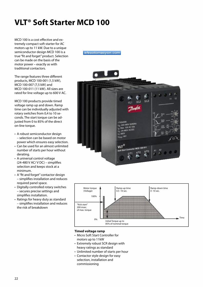
22
VLT® Soft Starter MCD 100
MCD 100 is a cost effective and ex- tremely compact soft starter for AC motors up to 11 kW. Due to a unique semiconductor design MCD 100 is a true “fit and forget” product. Selection can be made on the basis of the motor power – exactly as with traditional contactors.
The range features three different products, MCD 100-001 (1,5 kW), MCD 100-007 (7,5 kW) and MCD 100-011 (11 kW). All sizes are rated for line voltage up to 600 V AC.
MCD 100 products provide timed voltage ramp up and down. Ramp time can be individually adjusted with rotary switches from 0,4 to 10 se- conds. The start torque can be ad- justed from 0 to 85% of the direct on-line torque.
• A robust semiconductor design – selection can be based on motor power which ensures easy selection.• Can be used for an almost unlimited number of starts per hour without derating.• A universal control voltage (24-480 V AC/ V DC) – simplifies selection and keeps stock at a minimum.• A “fit and forget” contactor design – simplifies installation and reduces required panel space.• Digitally controlled rotary switches – secures precise settings and simplifies installation.• Ratings for heavy duty as standard – simplifies installation and reduces the risk of breakdown
Timed voltage ramp• Micro Soft Start Controller for motors up to 11kW• Extremely robust SCR design with heavy ratings as standard• Unlimited number of starts per hour• Contactor style design for easy selection, installation and commissioning
Motor torque(Voltage)
Ramp-up time0.5 -10 sec.
Ramp-down time0 -10 sec.
Time
’’Kick start’’200 msec.of max. torque
Initial Torque up to 85% of nominal torque
0%
100%
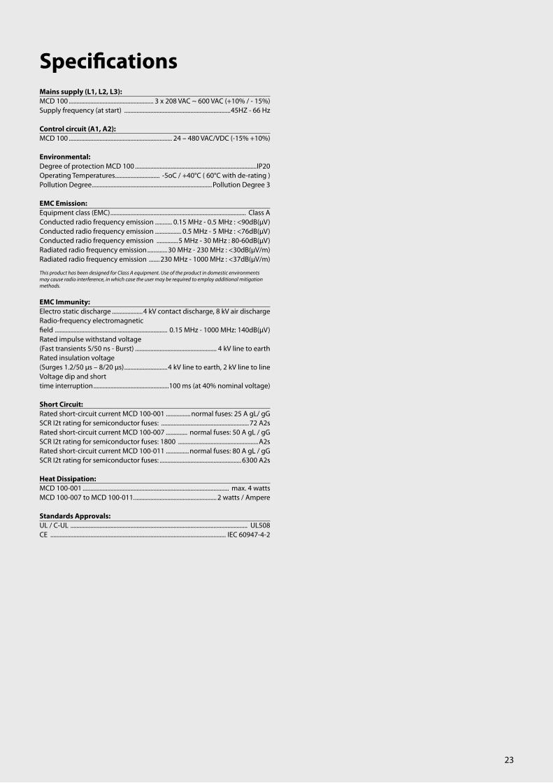
23
Mains supply (L1, L2, L3):MCD 100 ....................................................... 3 x 208 VAC ~ 600 VAC (+10% / - 15%)Supply frequency (at start) .....................................................................45HZ - 66 Hz
Control circuit (A1, A2):MCD 100 ................................................................... 24 – 480 VAC/VDC (-15% +10%)
Environmental:Degree of protection MCD 100 ...............................................................................IP20Operating Temperatures ............................. -5oC / +40°C ( 60°C with de-rating )Pollution Degree ..............................................................................Pollution Degree 3
EMC Emission:Equipment class (EMC) ........................................................................................ Class AConducted radio frequency emission ........... 0.15 MHz - 0.5 MHz : <90dB(µV)Conducted radio frequency emission ................. 0.5 MHz - 5 MHz : <76dB(µV)Conducted radio frequency emission ..............5 MHz - 30 MHz : 80-60dB(µV)Radiated radio frequency emission .............30 MHz - 230 MHz : <30dB(µV/m)Radiated radio frequency emission ....... 230 MHz - 1000 MHz : <37dB(µV/m)
This product has been designed for Class A equipment. Use of the product in domestic environments may cause radio interference, in which case the user may be required to employ additional mitigation methods.
EMC Immunity:Electro static discharge ....................4 kV contact discharge, 8 kV air dischargeRadio-frequency electromagnetic field ......................................................................... 0.15 MHz - 1000 MHz: 140dB(µV)Rated impulse withstand voltage (Fast transients 5/50 ns - Burst) ..................................................... 4 kV line to earthRated insulation voltage (Surges 1.2/50 µs – 8/20 µs) ............................4 kV line to earth, 2 kV line to lineVoltage dip and short time interruption .................................................100 ms (at 40% nominal voltage)
Short Circuit:Rated short-circuit current MCD 100-001 ................ normal fuses: 25 A gL/ gGSCR I2t rating for semiconductor fuses: .........................................................72 A2sRated short-circuit current MCD 100-007 .............. normal fuses: 50 A gL / gGSCR I2t rating for semiconductor fuses: 1800 ....................................................A2sRated short-circuit current MCD 100-011 ............... normal fuses: 80 A gL / gGSCR I2t rating for semiconductor fuses: .....................................................6300 A2s
Heat Dissipation:MCD 100-001 ............................................................................................... max. 4 wattsMCD 100-007 to MCD 100-011. ..................................................... 2 watts / Ampere
Standards Approvals:UL / C-UL ................................................................................................................... UL508CE .................................................................................................................. IEC 60947-4-2
Specifications

24
VLT® Compact Starter MCD 200
The Compact Starter MCD 200 cover the power range 7.5 – 110 kW.
Due to extensive use of the latest technology, such as new semicon-ductor control algorithms and bypass design, the new soft starters are very compact and heat dissipation is at a very low level. There is no need for extra ventilation or bypass contactors. This simplifies installation and keeps panel space at a minimum.
The MCD 200 features a variety of accessories. Add-on modules provide essential serial communication and a Remote Operator module allows for remote control and motor perform-ance monitoring, which makes MCD 200 ideal for panel installation.
MCD 200 comes in two versions. MCD 201 is the basic version offering timed voltage ramps, MCD 202 is the ad- vanced version providing current limit soft start, timed voltage ramp down, and motor protection.• Current ratings for normal and heavy starting• Versions for 200- 575 VAC• Voltage ramps or current limit ramp soft start• Built-in motor protection• Compact design with internal bypass system for minimum power loss• Add on modules for remote operation and serial communication• Software for sizing, control and monitoring
Timed voltage ramp MCD 201 Current Limit MCD202:• Compact Soft Starter for motors up to 110kW• Voltage ramps, current limit start and integrated motor protection• Integral bypass design reduce heat dissipation• Wide power range with advanced accessory modules
Optional:• Modules for serial communication• Remote operation kit• PC software• Remote operation kit
Ramp-up(2-20 seconds, Full Voltage Start)
Initial Torque(30-75%)
100%U
Ramp Time(2, 5, 15 seconds, OFF)
400%
300%
200%
100%
Initial Start Current(150% FLC, 200% FLC, 250% FLC)
I

25
Mains supply (L1, L2, L3):MCD 200-xxx-T4-xxx . ............................... 3 x 200 VAC ~ 440 VAC (+10% / - 15%)MCD 200-xxx-T6-xxx ................................ 3 x 200 VAC ~ 575 VAC (+10% / - 15%)Supply frequency (at start) ......................................................................45HZ - 66 HzSupply frequency ................................................................................ 48-62 Hz +/- 1%
Control supply (A1,AL2,A3):MCD 200-xxx-xx-CV1 ...................................................................24 VAC/VDC (±20%)MCD 200- xxx-xx-CV3 ............................................................... 110-240VAC (+10% /
- 15%) or 380-440 VAC (+10% / - 15%)
Control Inputs:Start Terminal N1 .......................................................Normally Open, 300 VAC max.Stop Terminal N2 .................................................... Normally Closed 300 VAC max.
Relay Outputs:Main Contactor (Terminals 13 & 14) ................................................Normally OpenMain Contactor (Terminals 13 & 14) ..............................6A, 30 VDC resistive / 2 A, 400 VAC, AC11Programmable Relay (Terminals 23 & 24) ......................................Normally OpenProgrammable Relay (Terminals 23 & 24). ............................ 6A, 30 VDC resistive / 2 A, 400 VAC, AC11
Environmental:Degree of protection MCD 200-007 to MCD 200-055 . .................................. IP20Degree of protection MCD 200-075 to MCD 200-110 . .................................. IP00Operating Temperatures ....................................................................... -10oC / +60oCHumidity .............................................................................5%-95% Relative HumidityPollution Degree . ........................................................................... Pollution Degree 3Vibration ...........................................................................IEC 60068 Test Fc SinusoidalVibration .............................................................4Hz - 13.2Hz: ± 1mm displacementVibration ......................................................................................13.2Hz - 100Hz: ± 0.7g
EMC Emission:Equipment class (EMC) ......................................................................................... Class AConducted radio frequency emission .......... 0.15 MHz - 0.5 MHz : <90dB(µV)Conducted radio frequency emissio .................... 0.5 MHz - 5 MHz : <76dB(µV)Conducted radio frequency emissio ..................5 MHz - 30 MHz : 80-60dB(µV)Radiated radio frequency emission .............30 MHz - 230 MHz : <30dB(µV/m)Radiated radio frequency emission ........ 230 MHz - 1000 MHz : <37dB(µV/m)
This product has been designed for Class A equipment. Use of the product in domestic environments may cause radio interference, in which case the user may be required to employ additional mitigation methods.
EMC Immunity:Equipment class (EMC) .....................4 kV contact discharge, 8 kV air dischargeRadio-frequency electromagnetic field ........................................0.15 MHz - 1000 MHz: 140dB(µV)Rated impulse withstand voltage (Fast transients 5/50 ns) ................................................................... 2 kV line to earthRated insulation voltage (Surges 1.2/50 µs – 8/20 ms) ..........................2 kV line to earth, 1 kV line to lineVoltage dip and short time interruption .....100 ms (at 40% nominal voltage)
Short Circuit:Rated short-circuit current MCD 200-007 to MCD 200-037 .........................5 kARated short-circuit current MCD 200-045 to MCD 200-110 . ..................... 10 kA
Heat Dissipation:During Start ..........................................................................................3 watts / AmpereDuring Run ............................................................................................................< 4 watts
Standards Approvals:C-tick ............................................................................................................. IEC 60947-4-2UL / C-UL ................................................................................................................... UL508CE ...................................................................................................................IEC 60947-4-2CCC ......................................................................................................................GB 14048.6
Specifications

26
VLT® Soft Starter MCD 3000
The VLT® MCD 3000 soft starters cover the power range 7,5 – 800 kW.
MCD 3000 is a total motor starting solution. Current transformers measure the motor current and provide feedback for controlled motor voltage ramp up, but also for numer-ous motor protection functions. A numeric display and logic keypad buttons makes programming easy and operational status such as motor current is shown via the display.
The MCD 3000 is wall mountable, however a Remote Operator module allows for remote control and motor performance monitoring making it ideal for panel installation.
• Current ratings for normal and heavy starting• Versions for 200 – 690 VAC• Current limit soft start with initial current ramp up• Four different auto-adjustable ramp down profiles• Numerous motor protection features• Built-in local control panel with display• Pass word protection of parameters• DC brake function• Internal delta wiring kit• Software for sizing, control and monitoring
Current ramp
MCD 3000• Fully featured Soft Starter for motors up to 800 kW• Total motor starting solution• Advanced start, stop and protection features• Local programming keypad and display
Optional:• Modules for serial communication• Remote operator kit• PC software
Remote operation kit• Start/stop, reset• LED for start, run, trip• Trip codes• Current display• Motor temp. display• 4 – 20 mA output
Full Voltage Stator Current
CU
RREN
T (%
Mot
or F
ull L
oad
Cur
rent
)
Ramp time(eg Par.4 = 10 secs)
Current Limit (eg. Par.2 = 400% x FLC)
Initial Current (eg. Par.3 = 250% x FLC)
ROTOR SPEED (% Full Speed)
10% 20% 30% 40% 50% 60% 70% 80% 90% 100%
700%
600%
500%
400%
300%
200%
100%

27
Mains supply (L1, L2, L3):Supply voltage MCD3000-T5 .........................................................................................................3 x 200 VAC ~ 525 VAC .....................................................3 x 200 VAC ~ 440 VAC (Inside Delta Connection)Supply voltage MCD3000-T7..........................................................................................................3 x 200 VAC ~ 690VAC .....................................................3 x 200 VAC ~ 440 VAC (Inside Delta Connection)Supply frequency (at start) .......................................50HZ (± 2Hz) / 60 Hz (± 2Hz)Supply frequency (during start) ................................>45Hz (50Hz supply) or >55Hz (60 Hz supply)Supply frequency (during run) .................................>48Hz (50Hz supply) or >58Hz (60 Hz supply)Electronics control voltage ........................................230 VAC (+10%/-15%) or 400 VAC (+10%/-15%)
Control Inputs:Start (Terminals 15 & 16). ...........Normally Open, Active 24 VDC, 8mA approx.Stop (Terminals 17 & 18) ..........Normally Closed, Active 24 VDC, 8mA approx.Reset (Terminals 25 & 26) ........Normally Closed, Active 24 VDC, 8mA approx.Parameter Set (Terminals 27 & 28) ......................Normally Open, Active 24 VDC, 8mA approx.
Relay Outputs:Programmable Output A1) (Terminals 13 & 14) ...........................Normally Open, 5 A @ 250 VAC/360 VA, 5 A @ 30 VDC resistiveProgrammable Output B2) (Terminals 21, 22 & 24) ................................. Changeover, 5 A @ 250 VAC/360 VA, 5 A @ 30 VDC resistiveOutput C3) (Terminals 33 & 34) ............................. Normally Open, , 5 A@250 VAC/360 VA, 5 A@30 VDC resistive1)Programmable functions: ........................................ Line contactor, Run, High current flag, Low current flag2)Programmable functions: ......... Tripped, Output on, High current flag, Low current flag, Line contactor3)Programmable functions: ................... Run, D.C.Brake Contactor Control, Off
Environmental:Degree of protection MCD3007 to MCD3132 . ................................................. IP21Degree of protection MCD3185 to MCD3800 ................................................... IP20Operating Temperatures . ........................................................................ -5oC / +60oCRated short-circuit current (with semi-conductor fuses) ...........................100kARated insulation voltage (Surges) .................2 kV line to earth, 1kV line to lineRated impulse withstand voltage (Fast transients) ..........................................2 kVPollution Degree . ............................................................................Pollution Degree 3Electro static discharge ....................4 kV contact discharge, 8 kV air dischargeEquipment class (EMC) ........................................................................................ Class ARadio-frequency electromagnetic field ............................................ 0.15 MHz - 80 MHz: 140dBµV 80 MHz - 1 GHz: 10 V/m
This product has been designed for Class A equipment. Use of the product in domestic environments may cause radio interference, in which case the user may be required to employ additional mitigation methods.
Standards Approvals:C√ ............................................................................................................................ CISPR-11UL1 ............................................................................................................................... UL508C-UL1 ....................................................................................................... CSA 22.2 No. 14CE . . ................................................................................................................IEC 60947-4-2
1) Requires use of semi-conductor fuses. Excludes models MCD3600~MCD3800
Specifications

28
VLT® Harmonic Filter AHF 005/010
The Danfoss AHF 005 and AHF 010 are advanced harmonic filters not to be confused with traditional harmonic trap filters. The Danfoss harmonic filters have been specially designed to match the Danfoss frequency drives.
AHF 010 reduces the harmonic current to less than 10% and the AHF 005 reduces the harmonic current to less than 5%.
Danfoss harmonic filters perform excellently.
The figures show the reduction of each of the sub-harmonic orders at full load.
Calculation Danfoss has created a PC based program MCT31 for calculation of harmonics with different principles for suppression. It can calculate the harmonics for Danfoss Frequency Converters depending on actual system (transformer, cables, other loads etc.)
Features• Small compact housing that fits into a panel• Easy to use in retrofit applications• AHF 010 reduces the total harmonic current distortion to 10%• AHF 005 reduces the total harmonic current distortion to 5%• One filter module can be used for several frequency drives• High efficiency (> 0.98)• User-friendly commissioning – no adjustment necessary• No routine maintenance required
Excellent performance
AHF 005
Hamonic order5 7 11 13 17 19 23 25
4%3%3%2%2%1%1%0%
AHF 010
Hamonic order
5 7 11 13 17 19 23 25
6%5%4%3%2%1%0%

29
General technical data:
The reduction of the low harmonic current emission to the rated THiD implies, that the THvD of the non-influenced mains voltage is lower than 2% and the ratio of short circuit power to installed load (R SCE ) is at least 66%.
Under these conditions the THiD of the mains current of the frequency converter is reduced to 10% or 5% (typical values at nominal load).
If these conditions are not or only partially fulfilled, a significant reduction of the harmonic components can still be achieved, but the rated THiD values may not be achieved.
Specifications

30
VLT® DriveMotor FCM 300The VLT ® FCM 300 Series is a very compact alternative to the traditional solution with a VLT® frequency con- verter and motor as separate units. The frequency converter is attached in place of the motor terminal box. It is no higher than the standard terminal box – not wider nor longer than the motor.
Benefits• Motor and drive perfectly matched to each other• No panel space required – the DriveMotor is placed on the machine• Simplified installation• No power cable length limitation• Straightforward EMC compliance• Flexible mounting – face-flange, foot/flange, foot/face• Retrofit without mechanical changes
FCM applicationsTypical applications are air handling units, pumps, conveyors and small machines for example labelling machines.
Control panelLocal control panel is used for operating, drivemotor setup and diagnostics. The LCP can be handheld or mounted in a panel front (IP 65).
Operation PadA local operation pad can be used for speed up/speed down, start/stop, and jog e.g.. Other features are speed indication by LED, mounting on FCM or kit for wall mounting.
Communication• RS 485 serial port as standard• Profibus DP version (3 or 12 Mbaud)

31
Mains supply, TT, TN and IT* (L1, L2, L3):Supply voltage 380-480 V units ......... 3 x 380/400/415/440/460/480 V ±10%Supply frequency .. ............................................................................................ 50/60 HzMax. imbalance of supply voltage .........................±2% of rated supply voltagePower factor / cos φ . ........................................................ max. 0.9/1.0 at rated loadNo. of switching operations on supply input L1, L2, L3 .............................................................. approx. 1 time/2 min*) Not valid for RFI class 1B units
Torque characteristics:Starting torque/overload torque ..................................................... 160 % for 1 min-Continuous torque.. ....................................................................................... see above
Control card, digital/pulse inputs:Number of programmable digital inputs ..................................................................4Terminal nos ........................................................................................... X101-2, -3, -4, -5Voltage level ... .......................................................... 0-24 V DC (PNP positive logics)Voltage level, logic ´0´ . ...................................................................................... < 5 V DCVoltage level, logic ´1´ . ....................................................................................> 10 V DCMaximum voltage on input .. ............................................................................28 V DCInput resistance, Ri ..........................................................................................aprox 2 kΩScanning time ........................................................................................................20 msec
Control card, pulse input:No. of programmable pulse inputs ............................................................................. 1Terminal nos. ........................................................................................................... X101-3Max. frequency on terminal 3, open collector/push pull 24 V ............................................................... 8 kHz/70 kHzResolution ................................................................................................................... .10 bitAccuracy (0.1-1 kHz), terminal 3 ..............................Max. error: 0.5% of full scaleAccuracy (1-12 kHz), terminal 3 ... ............................Max. error: 0.1% of full scale
Control card, analogue inputs:No. of programmable analogue voltage inputs . ....................................................1Terminal nos ............................................................................................................. X101-2Voltage level .................................................................................0 - 10 V DC (scalable)Input resistance, Ri... ................................................................................ approx. 10 kΩNo. of programmable analogue current inputs . ....................................................1Terminal no. . ............................................................................................................ X101-1Current range . ................................................................................ 0 - 20 mA (scalable)Input resistance, Ri. . ............................................................................. .approx. 500 kΩResolution ...................................................................................................................... 9 bitAccuracy on input .. .......................................................... Max. error 1% of full scaleScanning time ..... ............................................................................................... 20 msec.
Control card, digital/pulse and analogue outputs:No. of programmable digital and analogue outputs ............................................1Terminal nos ............................................................................................................. X101-9Voltage level at digital output/load .......................................... 0 - 24 V DC/25 mACurrent at analoque output .. ....................................................................... 0 - 20 mAMaximum load to frame (terminal 8) at analogue output . ............................................................................ RLOAD ≤ 500 ΩAccuracy of analogue output ... ...............................Max. error: 1.5% of full scaleResolution on analogue output. . ......................................................................... .8 bit
Relay output:No. of programmable outputs ......................................................................................1Terminal nos ................................................. 1-2 (make), 1-3 (brake) terminal X102Voltage level at contact/load (AC). ... ................................... 250 V AC, 5A-AC loadVoltage level at contact/load (DC) .30 V DC, 5A; 40 V DC, 2A . 100 V DC, .0.5A
Control card, RS 485 serial communication:Terminal nos ....................................................................................................... X100-1, -2
Control characteristics (frequency converter):Frequency range ............................................................................................... 0 - 132 HzResolution on output frequency ........................................................................ 0.1 %System response time ............................................................................ Max. 40 msec.Speed acuracy (open loop, CT mode, 4 P motor driven in speed range 150-1500 rPm) ......................................................+/- 15 rpm
Specifications

32
VLT® Motion Control Tool MCT 10Setup software provides easy control of details as well as a general over-view of systems, large or small.
• Handles all drive related data• One PC tool for all tasks• Handles all drives products and parameters• ”Explorer-like” view• Option programming• Online and offline commissioning• Scope & logging• Alarm history• Multiple interfaces for easy connection• USB• Profi bus• RS485• Internet download http://www.danfoss.com/drives
Basic:• Scope & Graph• Alarm history in saved projects• No limitation in number of drives• SyncPos support
Advanced:• PROFIsafe option• Copy protected “HW dongle”
More efficient commissioning • Off-line commissioning offsite• Save/send/mail projects anywhere• Easy field-bus handling, multiple drives in project file. Enables service organization to be more efficient
Enables service organization to be more efficient• Scope & logging: analyse problems easily• Read out alarms, warnings and fault log in one view.• Compare saved project with on-line drive
System requirements• MS Windows® NT 4.0, 2000 and XP• Pentium III 350 MHz or better• 256 Mb RAM or better• 200Mb free hard disk space• CD-ROM drive• VGA or XGA graphic adapter• Mouse
Features
Danfoss Drives A/S
E-Business
1. Download MCT 102. Download updates
Internet
Field-bus
Stand-alone
MCT 10 Set-up Software

33
VLT® Service – Your WayDriveProTM is an effi cient productivityprogramme tailored to meet your specifi c needs. All the necessary VLT® service facilities are at your disposal, which will minimize downtime and increase productivity at your factory. This means that DriveProTM pays for itself in no time.
DriveProTM service products are de-signed to be customised and com-bined.
Keep you running
Current drives update The SmartStep service programme ensures that Danfoss Products are replaced before breakdown.
Commissioning and regular adjustmentsThe mechanical condition of machin-ery changes over time. Regular adjust-ments can prevent failure messages and production stops.
Preventive maintenanceProactive maintenance gives you the peace of mind that comes with know-ing your drives have been properly inspected and maintained.
Keep you fi t
TrainingSpecialised service courses enable your own maintenance staff to carry out troubleshooting and service.
Stock maintenance & consignmentThe DriveProTM stock maintenance & consignment programme provides two variants of stock properties. Danfoss ensures the best choice of equipment is present at the stock.
Harmonic SurveyThe DriveProTM Harmonic Survey covers the installation of relevant instruments, as well as analysis and consultancy regarding actions to be taken.
Environmentally sound disposalDanfoss provides controlled environ-mentally sound disposal of redundant drives in line with local requirements.
Fix your costs
Fixed priceStick to your drive repair budget.Material, labour and transport to a Danfoss lab are included.
Post-warranty agreementAfter the 12-month factory warranty expires, you can extend your warranty up to 5 years. Contact your local Danfoss offi ce for an extended warranty.
Transport insuranceDanfoss takes full responsibility for damage to drives in transit.No complicated procedures.A simple note, and Danfoss will fi x it.
Response timeCustomised fast response service night and day keeps processes run-ning.

34
Albania [email protected] Tel: +30 210 94 11 744 Fax: +30 210 94 11 757 Angola [email protected] Tel: +27 11 803 8390 Fax: +27 11 803 8244
Argentina [email protected] Tel: +54 11 4756 4200 Fax: +54 11 4756 4100 Equitecnica S.A. [email protected] Tel: +54 11 49124590Fax: +54 11 49112382 Armenia [email protected] Tel: +7 095* 792 57 57 Fax: +7 095* 792 57 59
Aruba [email protected] Tel: +52 81 8156 5683 Fax: +52 81 8156 5625
[email protected] Tel: +61 (3) 9703 5100Fax: +61 (3) 9703 5159
Austria [email protected] Tel: +43 (2236) 5040Fax: +43 (2236) 5040 Ext. 43 Azerbaijan [email protected] Tel: +7 095* 792 57 57 Fax: +7 095* 792 57 59 Bahrain [email protected] Tel: +917 4 88 72220 Fax: +917 4 88 72221 Bangladesh [email protected] Tel: +91 (44) 55501555 Fax: +91 (44) 55501444 Barbados [email protected] Tel: +52 81 8156 5683 Fax: +52 81 8156 5625
Belarus [email protected] Tel: +7 095* 792 57 57 Fax: +7 095* 792 57 59 Belgium [email protected] Tel: +32 2 525 07 11 Fax: +32 2 525 07 57
Belize [email protected] Tel: +52 81 8156 5683 Fax: +52 81 8156 5625
Benin [email protected] Tel: +33 1 30 62 50 00 Fax: +33 1 30 62 51 93
Bosnia-Hercegovina Tel: +385 1 606 40 70 Fax: +385 1 606 40 80 Botswana [email protected] Tel: +27 11 803 8390 Fax: +27 11 803 8244
Brazil [email protected] Tel: +55 (11) 2135 5400Fax: +55 (11) 2135 5455 Bulgaria [email protected] Tel: +359 (2) 94 54 338Fax: +359 (2) 8409194 Burkina Faso [email protected] Tel: +33 1 30 62 50 00 Fax: +33 1 30 62 51 93 Burundi [email protected] Tel: +33 1 30 62 50 00 Fax: +33 1 30 62 51 93 Cameroon [email protected] Tel: +33 1 30 62 50 00 Fax: +33 1 30 62 51 93
Canada [email protected] Tel: +1 (905) 6766000 Fax: +1 (905) 6760279
Central Africa [email protected] Tel: +33 1 30 62 50 00 Fax: +33 1 30 62 51 93 Chile [email protected] Tel: +56 (2) 5200800 Fax: +56 (2) 7391055
ChinaTel: +86 10 6581 4800 Fax: +86 10 6581 4825 Colombia Tel: +57 2 439 8888Fax: +57 2 439 1909 Costa Rica [email protected] Tel: +52 81 8156 5683 Fax: +52 81 8156 5625
Croatia [email protected] Tel: +385 (1) 6064070Fax: +385 (1) 6064080 Cuba [email protected] Tel: +52 81 8156 5683Fax: +52 81 8156 5625 Ciniesa Tel: +53 7 24 14 24Fax: +53 7 24 17 25 Cyprus [email protected] Tel: +357 99451265 Fax: +357 25340608
Sales and Service Contacts worldwide · 24/7 availability · Local hotlines and local language · Local stock
Czech Republic [email protected] Tel: +420 (2) 83014111Fax: +420 (2) 83014123 Denmark [email protected] Tel: +45 8948 9111Fax: +45 8948 9311 Djibouti [email protected] Tel: +33 1 30 62 50 00 Fax: +33 1 30 62 51 93
Dominican Republic [email protected] Tel: +52 81 8156 5683Fax: +52 81 8156 5625 Ecuador [email protected] Tel: +593 (4) 2254300 Fax: +593 (4) 2254300
Egypt [email protected] Tel: +20 (2) 5261177Fax: +20 (2) 5261188 El Salvador [email protected] Tel: +52 81 8156 5683Fax: +52 81 8156 5625 Estonia [email protected] Tel: +372 6 59 33 00 Fax: +372 6 59 33 01 Finland [email protected] Tel: +358 9 802 81Fax: +358 9 802 8425 France [email protected] Tel: +33 (1) 30625000Fax: +33 (1) 30697470 Gambia [email protected] Tel: +33 1 30 62 50 00 Fax: +33 1 30 62 51 93 Georgia [email protected] Tel: +7 095* 792 57 57 Fax: +7 095* 792 57 59 Germany [email protected] Tel: +49 (69) 89020Fax: +49 (69) 8902324 Ghana [email protected] Tel: +33 1 30 62 50 00 Fax: +33 1 30 62 51 93
Great Britain [email protected] Tel: +44 0870 608 0008Fax: +44 0870 608 0009
Greece [email protected] Tel: +30 210 94 11 744 Fax: +30 210 94 11 757
Guatemala [email protected] Tel: +52 81 8156 5683Fax: +52 81 8156 5625 Honduras [email protected] Tel: +52 81 8156 5683Fax: +52 81 8156 5625 Hong Kong [email protected] Tel: +852 (25) 173872Fax: +852 (25) 173908 Hungary [email protected] Tel: +36 (1) 450 2531 Fax: +36 (1) 450 2539 Iceland [email protected] Tel: +354 510 4100 Fax: +354 510 4110 India [email protected] Tel: +91 (40) 27955270Fax: +91 40 3222009 Indonesia [email protected] Tel: +62 (21) 83790621 Fax: +62 (21) 83790620 Iran [email protected] Tel: +971 4 88 72 220 Fax: +971 4 88 722221
Iraq [email protected] Telephone: +964 1 778 2987 Ireland [email protected]: +353 (01) 626 8111Fax: +353 (01) 626 9334 Israel [email protected] Tel: +972 (3) 922 6688 Fax: +972 (3) 922 6655 Italy Tel: +39 (011) 3000511 Fax: +39 (011) 3000573 Jamaica [email protected] Tel: +52 81 8156 5683Fax: +52 81 8156 5625 Japan [email protected] Tel: +81 3 3330 1120
Jordan [email protected] Tel: +962 (6) 585 9472Fax: +962 (6) 585 9473 Kazakhstan [email protected]: +7 3272 93 95 05 Fax: +7 3272 93 82 93 Kenya [email protected] Tel: +27 11 803 8390 Fax: +27 11 803 8244
35
Korea (South) [email protected] Tel: +82 (2) 567-0090Fax: +82 (2) 569-2894 Kuwait [email protected] Tel: +971 4 88 72220 Fax: +971 4 88 72221
Kyrgyzstan [email protected] Tel: +7 095* 792 57 57 Fax: +7 095* 792 57 59 Latvia [email protected] Tel: +371 7 339166Fax: +371 7 36 13 13
Lesotho [email protected] Tel: +27 11 803 8390 Fax: +27 11 803 8244 Liberia [email protected] Tel: +33 1 30 62 50 00 Fax: +33 1 30 62 51 93
Libya Please contact Danfoss in South Africa Lithuania [email protected] Tel: +370 52105 740Fax: +370 52 335 355
Macedonia [email protected] Tel: +381 11 313 0620 Fax: +381 11 313 0636
Madagascar [email protected] Tel: +33 1 30 62 50 00 Fax: +33 1 30 62 51 93
Malawi [email protected] Tel: +27 11 803 8390 Fax: +27 11 803 8244
Malaysia [email protected] Tel: +60 3-7845 1608 Fax: +60 3-7845 1609 Mali [email protected] Tel: +33 1 30 62 50 00 Fax: +33 1 30 62 51 93
Malta [email protected] Tel: +356 21467966Fax: +356 21467966
Mexico [email protected] Tel: +52 (81) 8156 5683Fax: +52 (81) 8156 5625 Morocco [email protected] Tel: +33 1 30 62 50 00 Fax: +33 1 30 62 51 93 Mozambique [email protected] Tel: +27 11 803 8390 Fax: +27 11 803 8244 Namibia Tel: +26 4 61 26 2876 Fax: +26 4 61 26 2894
Netherlands Tel: +31 10 249 2000Fax: +31 (10) 249 2001 New Caledonia [email protected] Tel: +33 1 30 62 50 00 Fax: +33 1 30 62 51 93 Nicaragua [email protected] Tel: +52 81 8156 5683Fax: +52 81 8156 5625 Niger [email protected] Tel: +33 1 30 62 50 00 Fax: +33 1 30 62 51 93 Nigeria [email protected] Tel: +234 1775 1137 Norway [email protected] Tel: +47 67 17 72 00Fax: +47 67 13 68 50 Pakistan [email protected] Tel: +92 21 452 6002/3/4Fax: +92 21 454 5995 Panama [email protected]: +52 81 8156 5683Fax: +52 81 8156 5625 Paraguay [email protected] Tel: +595 21 202615Fax: +595 21 213819 Peru Tel: +51 1 478 0808 Fax: +51 1 362 5191 Philippines [email protected]: +63 2 809 7130 Fax: +63 2 809 7271 Poland [email protected]: +48 (22) 755 0700Fax: +48 (22) 755 0701 [email protected] Tel: +351 214 248 934 Fax: +351 214 172 466 Puerto Rico [email protected] Tel: +52 81 8156 5683Fax: +52 81 8156 5625 Qatar [email protected] Tel: +971 4 88 72220 Fax: +971 4 88 72221 Réunion [email protected] Tel: +33 1 30 62 50 00 Fax: +33 1 30 62 51 93 Romania [email protected] Tel: +40 21 335 52 02 Fax: +40 21 335 55 59 Russian Federation [email protected] Tel: +7 495 792 57 57 Fax: +7 495 792 57 59
Rwanda [email protected] Tel: +33 1 30 62 50 00 Fax: +33 1 30 62 51 93 Saudi Arabia [email protected] Tel: +971 4 88 72220 Fax: +971 4 88 72221 Senegal [email protected] Tel: +33 1 30 62 50 00 Fax: +33 1 30 62 51 93 Serbia & Montenegro [email protected] Tel: +381 11 313 0620 Fax: +381 11 313 0636
Seychelles [email protected] Tel: +27 11 803 8390 Fax: +27 11 803 8244 Sierra Leone [email protected] Tel: +33 1 30 62 50 00 Fax: +33 1 30 62 51 93 Singapore [email protected]: +65 (6) 885 9788Fax: +65 (6) 885 9799 Slovak Republic [email protected] Tel: +421 (37) 6406280Fax: +421 (37) 6406290 Slovenia [email protected] Tel: +386 1 518 6108Fax: +386 1 507 25 18 South Africa [email protected] Tel: +27 11 803 8390Fax: +27 11 803 8244 Spain Tel: +34 91 658 66 88 Fax: +34 91 663 73 70 Sri Lanka [email protected]: +94 115343190Fax: +94 115343191 Swaziland [email protected] Tel: +27 11 803 8390 Fax: +27 11 803 8244
Sweden [email protected] Tel: +46 1325 8500 Fax: +46 1313 0181 Switzerland [email protected] Tel: +41 (61)-906 11 11 Fax: +41 (61)-906 11 21 Syria [email protected] Tel: +963 94 423 421 Fax: +963 11 212 94 67 Taiwan [email protected] Tel: +886 (0) 2 8226 3263 Fax: +886 (0) 2 8226 3269
Tajikistan [email protected] Tel: +7 095* 792 57 57 Fax: +7 095* 792 57 59 Tanzania [email protected] Tel: +27 11 803 8390 Fax :+27 11 803 8244 Thailand [email protected] Tel: +66 2 379 9800Fax: +66 2 379 9801 Tunisia [email protected] Tel: +33 1 30 62 50 00 Fax: +33 1 30 62 51 93 Turkey [email protected] Tel: +90 212 356 6110Fax: +90 212 356 6251 Turkmenistan [email protected] Tel: +7 095* 792 57 57 Fax: +7 095* 792 57 59 Ukraine [email protected] Tel: +380 44 4618700Fax: +380 44 4618707 United Arab Emirates [email protected] Tel: +971 4 88 72220 Fax: +971 4 88 72221 Uruguay [email protected] Tel: +598 2 601 5751 Fax: +598 2 601 5741 USA [email protected] Tel: +1 (815) 639-8600 Fax: +1 (815) 639-80002 Uzbekistan [email protected] Tel: +7 095* 792 57 57 Fax: +7 095* 792 57 59 Venezuela [email protected]: +58 241 832 4444 Fax: +58 241 832 8409 Vietnam [email protected] Tel: +84 88 106 806 (5 lines) Fax: +84 88 106 805 Yemen [email protected] Tel: +971 4 88 72220 Fax: +971 4 88 72221
Zambia [email protected] Tel: +27 11 803 8390 Fax: +27 11 803 8244 Zimbabwe [email protected] Tel: +27 11 803 8390 Fax: +27 11 803 8244

DKDD.PB.101.A2.02 VLT® is a registered Danfoss trademark www.simpatico.dk.2006.03
What VLT® is all about
Dedicated to drivesDedication has been a key word since 1968, when Danfoss introduced the world’s first mass produced variable speed drive for AC motors – and named it VLT®.Two thousand employees develop, manufacture, sell and service drives and softstarters in more than one hundred countries – and nothing but drives and softstarters.
Intelligent and innovative Developers at Danfoss Drives have fully adopted modular principles in development as well as design, pro- duction and configuration. Tomorrow’s features are developed in parallel using dedicated technology platforms. This allows the develop-ment of each element to take in parallel, at the same time reducing time to market and ensuring that customers always enjoy the benefits of the latest features.
Depend on the expertsWe take responsibility for every element in our products. The fact that we develop and produce our own features, hardware, software, power modules, printed circuit boards, and accessories is your guarantee for reliable products.
Danfoss Drives is the world leader among dedicated drives providers – and still gaining market shares.
Local backup – globallyVLT® motor controls are operating in applications all over the world and Danfoss Drives, experts are ready to support our customers with applica-tion advice and service wherever they may be.
Danfoss Drives experts only ever stop when the customer’s drive problems are solved.
The head factory in Graasten, Denmark.