Embed Size (px)
Citation preview
International Journal of Electrical Engineering and Technology (IJEET), ISSN 0976 –
6545(Print), ISSN 0976 – 6553(Online) Volume 4, Issue 2, March – April (2013), © IAEME
81
APPLICATION OF CROWBAR PROTECTION ON DFIG-BASED
WIND TURBINE CONNECTED TO GRID
Nadiya G. Mohammed
1 M. Tech. candidate, Electrical Engineering, Department of Bharat Vidyapeeth University
College of Engineering Pune, India.
ABSTRACT
To provide voltage stability support in weak transmission networks for the ability of
doubly fed induction generators is investigated in this paper. Here we analyzed the response
of wind turbines to voltage dips at the point of common coupling and its effects on system
stability. In order to support the grid voltage by injecting reactive power during and after grid
fault events, we developed a control strategy for the operation of the grid and rotor side
converters. To study performance of strategy, it is analyzed for different voltage dips at the
point of common coupling of a wind farm and compared with the case when the converters
do not provide any voltage support. The Chilean transmission network model is used for the
Simulations, because of its radial Configuration it would be a good example of weak power
system. In addition to this we are presenting the theoretical analysis of the fault current for
the application of crowbar protection. The basic method for the fault current measurement
during the unsymmetrical and symmetrical faults in the grid system is discussed. In this
paper we presented the analytical model for crowbar protection rather than doing simulation
studies in actual.
Keywords- Doubly fed induction generator (DFIG); unbalanced grid fault; fault ride-
through; Crowbar protection; Analytic Hierarchy Process; squirrel cage induction generator
SCIG.
INTERNATIONAL JOURNAL OF ELECTRICAL ENGINEERING
& TECHNOLOGY (IJEET)
ISSN 0976 – 6545(Print) ISSN 0976 – 6553(Online) Volume 4, Issue 2, March – April (2013), pp. 81-92
© IAEME: www.iaeme.com/ijeet.asp Journal Impact Factor (2013): 5.5028 (Calculated by GISI) www.jifactor.com
IJEET
© I A E M E
International Journal of Electrical Engineering and Technology (IJEET), ISSN 0976 –
6545(Print), ISSN 0976 – 6553(Online) Volume 4, Issue 2, March – April (2013), © IAEME
82
I. INTRODUCTION
The trend in wind generation has been the installation of large and concentrated wind
farms into electrical power networks in last year’s. As a result, wind power has reached in
some regions significant penetration levels imposing new problems to the Transmission
System Operators (TSO). Wind power injections are already exceeding local demand in some
regions like Spain & Northern Germany.
In many countries, this problem has demanded the creation of new grid requirements
for wind generators. Disconnection of wind turbines in case of disturbance is not admitted
anymore, and voltage and transient stability support -during and after grid fault events- are
required [1]-[2].During disturbances the risk of losing a significant fraction of wind generators
is decreases and grid operators can guarantee a reliable and secure power system operation
even by high wind power penetration levels.
In variable speed wind turbines, Doubly Fed Induction Generators (DFIG) is the most
common technology used. In Europe in 2005 [3] 45% of the medium to large wind turbines
installed. The active and reactive power injected into the grid is controlled by using power
converters enables DFIG to operate at optimal rotor speed and to maximize power generation
in normal grid conditions. In case of voltage dips close to the wind farm, high currents will
pass through the stator winding, which will also flow through the rotor winding due to the
magnetic coupling between stator and rotor. A protection to system is required because it
causes high currents that could damage the converters. By short circuiting the generator rotor
through a crowbar and thus blocking the rotor side converter [4] protection is achieved. Once
the rotor side converter is blocked, the DFIG operates like a typical induction generator and
therefore, the control of active and reactive power through the rotor is inactive.
To provide insight and understanding about the effective Fault Ride-Through (FRT)
capability of DFIG in weak transmission networks and its effects on system stability is a paper
aim. A control strategy allowing the grid and rotor side converters to support the grid voltage
by injecting reactive power during and after grid faults is developed. Using the Chilean
transmission network simulations are performed, which can be considered a weak power
system.
The analysis into grid fault ride-through of wind turbines has flourished within the last
years and this truth underlines by itself the relevancy of the subject. A large number of papers
made by academics are accompanied by advanced hardware and software system solutions
adopted within the new wind turbines by makers to assure grid fault ride-through capability.
The competition within the field among makers is fierce and this makes it terribly tough to
induce careful data on the actual grid fault ride-through technical solutions adopted in
industrial wind turbines.
This paper deals with the behavior of wind turbines during grid disturbances. Below
are major objectives of this paper:
- Analyze the short-circuit current fed into the grid by DFIG wind turbines each with
crowbar and DC-chopper protection.
- Analyze the fault current contribution of wind farms.
- Investigate voltage profiles ensuing from faults at sub-transmission and medium voltage
networks to know if issues for grid fault ride-through of wind turbines could arise.
- Investigate and devise potential ways that to boost voltage support by wind farms in weak
networks throughout a grid disturbance.
In below sections we are discussing above stated things one by one.
International Journal of Electrical Engineering and Technology (IJEET), ISSN 0976 –
6545(Print), ISSN 0976 – 6553(Online) Volume 4, Issue 2, March – April (2013), © IAEME
83
II. MODELING AND CONTROL OF DFIG
A. Wind Turbines with DFIG
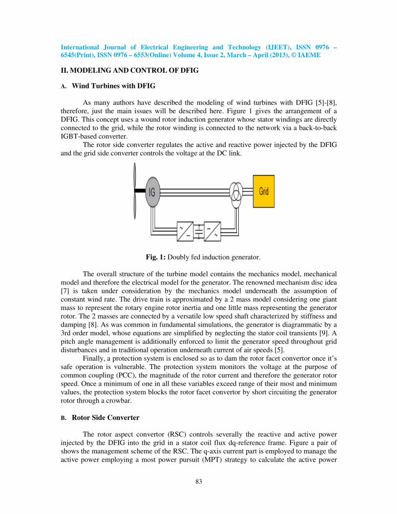
As many authors have described the modeling of wind turbines with DFIG [5]-[8],
therefore, just the main issues will be described here. Figure 1 gives the arrangement of a
DFIG. This concept uses a wound rotor induction generator whose stator windings are directly
connected to the grid, while the rotor winding is connected to the network via a back-to-back
IGBT-based converter.
The rotor side converter regulates the active and reactive power injected by the DFIG
and the grid side converter controls the voltage at the DC link.
Fig. 1: Doubly fed induction generator.
The overall structure of the turbine model contains the mechanics model, mechanical
model and therefore the electrical model for the generator. The renowned mechanism disc idea
[7] is taken under consideration by the mechanics model underneath the assumption of
constant wind rate. The drive train is approximated by a 2 mass model considering one giant
mass to represent the rotary engine rotor inertia and one little mass representing the generator
rotor. The 2 masses are connected by a versatile low speed shaft characterized by stiffness and
damping [8]. As was common in fundamental simulations, the generator is diagrammatic by a
3rd order model, whose equations are simplified by neglecting the stator coil transients [9]. A
pitch angle management is additionally enforced to limit the generator speed throughout grid
disturbances and in traditional operation underneath current of air speeds [5].
Finally, a protection system is enclosed so as to dam the rotor facet convertor once it’s
safe operation is vulnerable. The protection system monitors the voltage at the purpose of
common coupling (PCC), the magnitude of the rotor current and therefore the generator rotor
speed. Once a minimum of one in all these variables exceed range of their most and minimum
values, the protection system blocks the rotor facet convertor by short circuiting the generator
rotor through a crowbar.
B. Rotor Side Converter
The rotor aspect convertor (RSC) controls severally the reactive and active power
injected by the DFIG into the grid in a stator coil flux dq-reference frame. Figure a pair of
shows the management scheme of the RSC. The q-axis current part is employed to manage the
active power employing a most power pursuit (MPT) strategy to calculate the active power
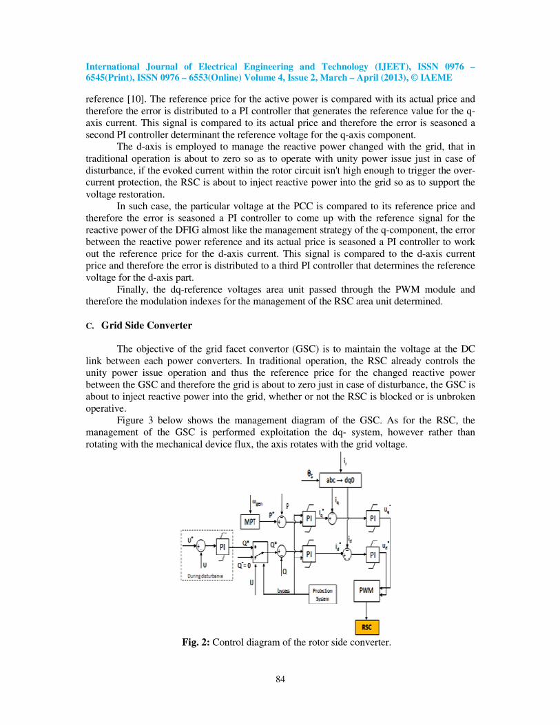
International Journal of Electrical Engineering and Technology (IJEET), ISSN 0976 –
6545(Print), ISSN 0976 – 6553(Online) Volume 4, Issue 2, March – April (2013), © IAEME
84
reference [10]. The reference price for the active power is compared with its actual price and
therefore the error is distributed to a PI controller that generates the reference value for the q-
axis current. This signal is compared to its actual price and therefore the error is seasoned a
second PI controller determinant the reference voltage for the q-axis component.
The d-axis is employed to manage the reactive power changed with the grid, that in
traditional operation is about to zero so as to operate with unity power issue just in case of
disturbance, if the evoked current within the rotor circuit isn't high enough to trigger the over-
current protection, the RSC is about to inject reactive power into the grid so as to support the
voltage restoration.
In such case, the particular voltage at the PCC is compared to its reference price and
therefore the error is seasoned a PI controller to come up with the reference signal for the
reactive power of the DFIG almost like the management strategy of the q-component, the error
between the reactive power reference and its actual price is seasoned a PI controller to work
out the reference price for the d-axis current. This signal is compared to the d-axis current
price and therefore the error is distributed to a third PI controller that determines the reference
voltage for the d-axis part.
Finally, the dq-reference voltages area unit passed through the PWM module and
therefore the modulation indexes for the management of the RSC area unit determined.
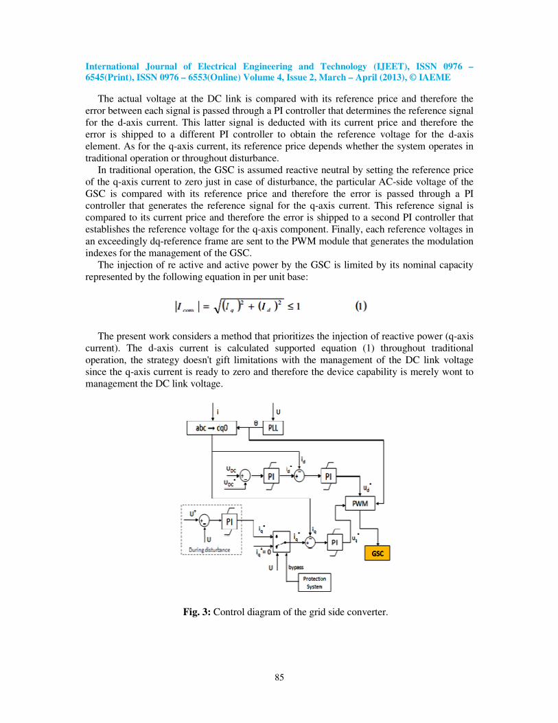
C. Grid Side Converter
The objective of the grid facet convertor (GSC) is to maintain the voltage at the DC
link between each power converters. In traditional operation, the RSC already controls the
unity power issue operation and thus the reference price for the changed reactive power
between the GSC and therefore the grid is about to zero just in case of disturbance, the GSC is
about to inject reactive power into the grid, whether or not the RSC is blocked or is unbroken
operative.
Figure 3 below shows the management diagram of the GSC. As for the RSC, the
management of the GSC is performed exploitation the dq- system, however rather than
rotating with the mechanical device flux, the axis rotates with the grid voltage.
Fig. 2: Control diagram of the rotor side converter.
International Journal of Electrical Engineering and Technology (IJEET), ISSN 0976 –
6545(Print), ISSN 0976 – 6553(Online) Volume 4, Issue 2, March – April (2013), © IAEME
85
The actual voltage at the DC link is compared with its reference price and therefore the
error between each signal is passed through a PI controller that determines the reference signal
for the d-axis current. This latter signal is deducted with its current price and therefore the
error is shipped to a different PI controller to obtain the reference voltage for the d-axis
element. As for the q-axis current, its reference price depends whether the system operates in
traditional operation or throughout disturbance.
In traditional operation, the GSC is assumed reactive neutral by setting the reference price
of the q-axis current to zero just in case of disturbance, the particular AC-side voltage of the
GSC is compared with its reference price and therefore the error is passed through a PI
controller that generates the reference signal for the q-axis current. This reference signal is
compared to its current price and therefore the error is shipped to a second PI controller that
establishes the reference voltage for the q-axis component. Finally, each reference voltages in
an exceedingly dq-reference frame are sent to the PWM module that generates the modulation
indexes for the management of the GSC.
The injection of re active and active power by the GSC is limited by its nominal capacity
represented by the following equation in per unit base:
The present work considers a method that prioritizes the injection of reactive power (q-axis
current). The d-axis current is calculated supported equation (1) throughout traditional
operation, the strategy doesn't gift limitations with the management of the DC link voltage
since the q-axis current is ready to zero and therefore the device capability is merely wont to
management the DC link voltage.
Fig. 3: Control diagram of the grid side converter.
International Journal of Electrical Engineering and Technology (IJEET), ISSN 0976 –
6545(Print), ISSN 0976 – 6553(Online) Volume 4, Issue 2, March – April (2013), © IAEME
86
III. DFIG USING CROWBAR PROTECTION
A DFIG using crowbar protection is considered in this section. The analysis assumes
that the crowbar remains connected during the whole duration of the fault, 250 ms in this
study. This may not be the case for three-phase faults since the RSC would be re-started as
soon as the rotor current decays below a certain predefined value. During symmetrical faults,
the analysis here presented is therefore applicable during the period between crowbar insertion
and RSC re-starting. However, for unsymmetrical faults, the RSC will most likely not be re-
started during the fault since the cause of high rotor current is the negative sequence network
voltage which does not decay during the fault period (Semaan 2006(b)). For the most severe
unsymmetrical faults, the proposed analysis is therefore applicable during the whole duration
of the fault.
The method proposed above for calculating the short-circuit current of a SCIG cannot
be directly applied to a wind turbine driven DFIG, because of mainly two reasons.
The first reason is that the value of the crowbar resistance may be up to 20 times the value
of the generator rotor resistance (Akhmatov 2005) and the total resulting rotor resistance can
no longer be neglected. In (Morren 2007) it has been proposed a method for calculating the
maximum short-circuit current of a DFIG with high crowbar resistance during a symmetrical
three phase fault at the generator terminals. The authors of the mentioned reference proposed
to include the effects of the crowbar resistance to calculate the maximum short-circuit current
of a DFIG in two steps. First, the rotor transient time constant is modified according to:
1
The second step to account for the presence of the high crowbar resistance proposed in
(Morren 2007) is to include it in the impedance limiting the short-circuit current.
However, this proved to be still a too rough approximation when comparing with the
simulations, leading to inaccurate calculations of the DFIG short-circuits current as a function
of time.
The second reason, that makes the SCIG short-circuit current calculation method
inaccurate when applied to a wind turbine driven DFIG, is that a wind turbine driven DFIG
may operate in a slip range between -0.3 and +0.3. The forced stator and rotor fluxes, which
for the SCIG have been calculated based on the assumption of zero slip, for a DFIG should be
calculated based on its initial rotor speed and delivered active and reactive power.
D. Influence of high crowbar resistance on natural stator flux
Let us start with the stator transient time constant. For a DFIG with high total rotor
resistance, the stator transient time constant needs to be expressed in a slightly different way.
The natural stator flux, which is fixed with respect to the stator, generates a voltage in the rotor
whose frequency and magnitude in a rotor reference frame are proportional to the rotor speed.
A current will flow in the rotor, having the same frequency of the induced voltage and
opposite to the rotor speed.
International Journal of Electrical Engineering and Technology (IJEET), ISSN 0976 –
6545(Print), ISSN 0976 – 6553(Online) Volume 4, Issue 2, March – April (2013), © IAEME
87
E. Influence of high crowbar resistance on natural rotor flux
Let us denote the natural rotor flux immediately after the fault as rn. In the SCIG case,
this flux in a rotor reference frame is a DC component decaying with the rotor transient time
constant. This fact is no longer true for a DFIG with high rotor resistance. To explain why this
no longer holds, we may find it useful to refer to a simpler analogous situation.
F. Influence of high crowbar resistance on negative sequence fluxes
The rotor negative sequence current can be obtained with a simple current division
between the magnetizing and the rotor circuit branches, as done for a SCIG.
G. Wind turbine driven DFIG
The initial slip of a wind turbine driven DFIG may be significantly different from zero,
thus the initial and post-fault forced components of the rotor flux can no longer be calculated
under the assumption of zero rotor current.
The pre-fault rotor flux must also be re-calculated taking into account the initial
conditions of the DFIG. If the initial apparent power, fed into the grid according to generator
convention, and rotor slip of the DFIG are known, the pre-fault rotor flux is calculated.
There are different simulations studies carried out for this protection systems which are out
of scope of this paper. Based on these studies we are making following summary:
H. Summary
From the studied simulation results, an approximate method for predicting the
symmetrical and unsymmetrical short-circuit current of a SCIG and a DFIG has been
proposed. The proposed method gives a good prediction of the short-circuit behavior of a wind
farm using a DFIG with crowbar protection, both for symmetrical and unsymmetrical faults in
the network. A linear model of the induction machine has been considered and saturation has
been neglected.
The accuracy of the results obtained with the proposed method may be sufficient to
replace the use of simulations in many contexts, e.g. calculation of maximum current,
calculation of its DC and AC components and short circuit calculations for protection relays
settings. The impedances of step-up transformer and MV line should be added in series with
the DFIG stator impedance. Even though these impedances may have a non-negligible
resistive part, it has been found that in practical situations this fact does not affect the accuracy
of the method. Moreover, the method is capable of accurately reproducing the DFIG fault
current even for unsymmetrical faults on the MV side of the step-up transformer.
A factor that may limit the accuracy of the proposed method is the delay with which
the crowbar resistance is inserted relative to the fault inception instant. Delays below 5 ms
result in almost no loss of accuracy.
IV. DYNAMIC SIMULATIONS
The simulations performed in this work are based on the Chilean transmission system.
The voltages in the bulk network are from 110 to 500 kV with nearly 750 busbars and 220
generators. The installed capacity of the system is about 10.000 MW for a peak load of 6.000
International Journal of Electrical Engineering and Technology (IJEET), ISSN 0976 –
6545(Print), ISSN 0976 – 6553(Online) Volume 4, Issue 2, March – April (2013), © IAEME
88
MW. The system is characterized by long distances between major load centers and generation
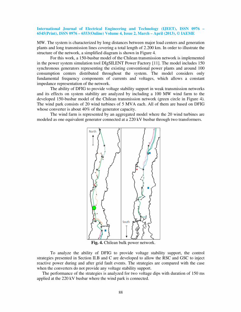
plants and long transmission lines covering a total length of 2.200 km. In order to illustrate the
structure of the network, a simplified diagram is shown in Figure 4.
For this work, a 150-busbar model of the Chilean transmission network is implemented
in the power system simulation tool DIgSILENT Power Factory [11]. The model includes 150
synchronous generators representing the existing conventional power plants and around 100
consumption centers distributed throughout the system. The model considers only
fundamental frequency components of currents and voltages, which allows a constant
impedance representation of the network.
The ability of DFIG to provide voltage stability support in weak transmission networks
and its effects on system stability are analyzed by including a 100 MW wind farm to the
developed 150-busbar model of the Chilean transmission network (green circle in Figure 4).
The wind park consists of 20 wind turbines of 5 MVA each. All of them are based on DFIG
whose converter is about 40% of the generator capacity.
The wind farm is represented by an aggregated model where the 20 wind turbines are
modeled as one equivalent generator connected at a 220 kV busbar through two transformers.
Fig. 4. Chilean bulk power network.
To analyze the ability of DFIG to provide voltage stability support, the control
strategies presented in Section II.B and C are developed to allow the RSC and GSC to inject
reactive power during and after grid fault events. The strategies are compared with the case
when the converters do not provide any voltage stability support.
The performance of the strategies is analyzed for two voltage dips with duration of 150 ms
applied at the 220 kV busbar where the wind park is connected.
International Journal of Electrical Engineering and Technology (IJEET), ISSN 0976 –
6545(Print), ISSN 0976 – 6553(Online) Volume 4, Issue 2, March – April (2013), © IAEME
89
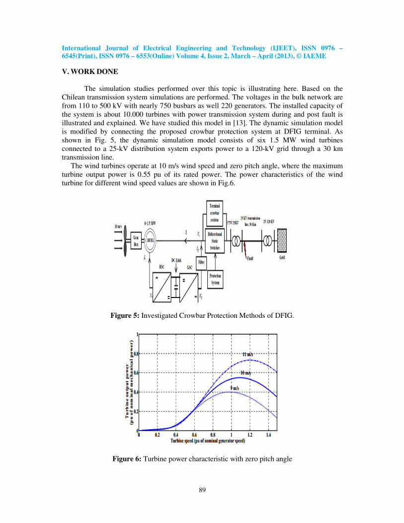
V. WORK DONE
The simulation studies performed over this topic is illustrating here. Based on the
Chilean transmission system simulations are performed. The voltages in the bulk network are
from 110 to 500 kV with nearly 750 busbars as well 220 generators. The installed capacity of
the system is about 10.000 turbines with power transmission system during and post fault is
illustrated and explained. We have studied this model in [13]. The dynamic simulation model
is modified by connecting the proposed crowbar protection system at DFIG terminal. As
shown in Fig. 5, the dynamic simulation model consists of six 1.5 MW wind turbines
connected to a 25-kV distribution system exports power to a 120-kV grid through a 30 km
transmission line.
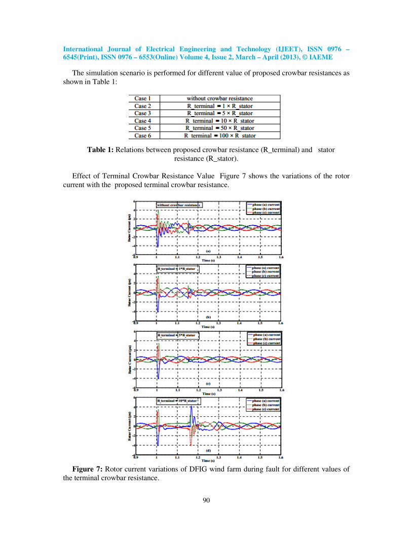
The wind turbines operate at 10 m/s wind speed and zero pitch angle, where the maximum
turbine output power is 0.55 pu of its rated power. The power characteristics of the wind
turbine for different wind speed values are shown in Fig.6.
Figure 5: Investigated Crowbar Protection Methods of DFIG.
Figure 6: Turbine power characteristic with zero pitch angle
International Journal of Electrical Engineering and Technology (IJEET), ISSN 0976 –
6545(Print), ISSN 0976 – 6553(Online) Volume 4, Issue 2, March – April (2013), © IAEME
90
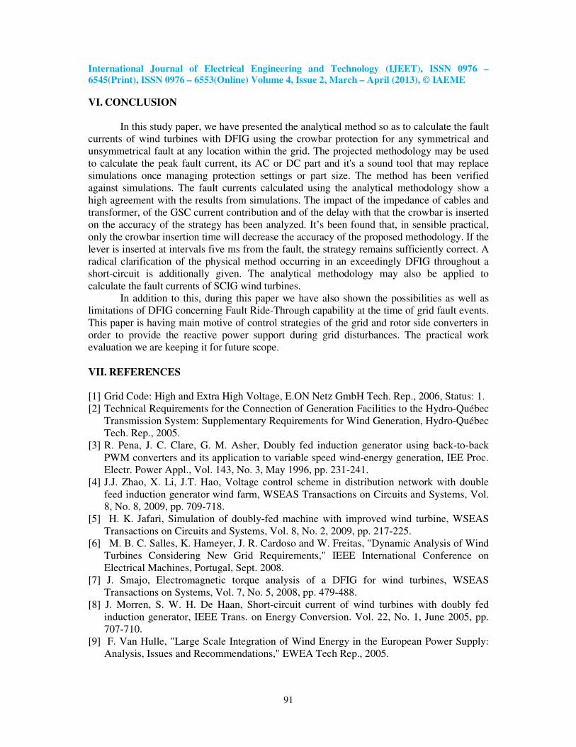
The simulation scenario is performed for different value of proposed crowbar resistances as
shown in Table 1:
Table 1: Relations between proposed crowbar resistance (R_terminal) and stator
resistance (R_stator).
Effect of Terminal Crowbar Resistance Value Figure 7 shows the variations of the rotor
current with the proposed terminal crowbar resistance.
Figure 7: Rotor current variations of DFIG wind farm during fault for different values of
the terminal crowbar resistance.
International Journal of Electrical Engineering and Technology (IJEET), ISSN 0976 –
6545(Print), ISSN 0976 – 6553(Online) Volume 4, Issue 2, March – April (2013), © IAEME
91
VI. CONCLUSION
In this study paper, we have presented the analytical method so as to calculate the fault
currents of wind turbines with DFIG using the crowbar protection for any symmetrical and
unsymmetrical fault at any location within the grid. The projected methodology may be used
to calculate the peak fault current, its AC or DC part and it's a sound tool that may replace
simulations once managing protection settings or part size. The method has been verified
against simulations. The fault currents calculated using the analytical methodology show a
high agreement with the results from simulations. The impact of the impedance of cables and
transformer, of the GSC current contribution and of the delay with that the crowbar is inserted
on the accuracy of the strategy has been analyzed. It’s been found that, in sensible practical,
only the crowbar insertion time will decrease the accuracy of the proposed methodology. If the
lever is inserted at intervals five ms from the fault, the strategy remains sufficiently correct. A
radical clarification of the physical method occurring in an exceedingly DFIG throughout a
short-circuit is additionally given. The analytical methodology may also be applied to
calculate the fault currents of SCIG wind turbines.
In addition to this, during this paper we have also shown the possibilities as well as
limitations of DFIG concerning Fault Ride-Through capability at the time of grid fault events.
This paper is having main motive of control strategies of the grid and rotor side converters in
order to provide the reactive power support during grid disturbances. The practical work
evaluation we are keeping it for future scope.
VII. REFERENCES
[1] Grid Code: High and Extra High Voltage, E.ON Netz GmbH Tech. Rep., 2006, Status: 1.
[2] Technical Requirements for the Connection of Generation Facilities to the Hydro-Québec
Transmission System: Supplementary Requirements for Wind Generation, Hydro-Québec
Tech. Rep., 2005.
[3] R. Pena, J. C. Clare, G. M. Asher, Doubly fed induction generator using back-to-back
PWM converters and its application to variable speed wind-energy generation, IEE Proc.
Electr. Power Appl., Vol. 143, No. 3, May 1996, pp. 231-241.
[4] J.J. Zhao, X. Li, J.T. Hao, Voltage control scheme in distribution network with double
feed induction generator wind farm, WSEAS Transactions on Circuits and Systems, Vol.
8, No. 8, 2009, pp. 709-718.
[5] H. K. Jafari, Simulation of doubly-fed machine with improved wind turbine, WSEAS
Transactions on Circuits and Systems, Vol. 8, No. 2, 2009, pp. 217-225.
[6] M. B. C. Salles, K. Hameyer, J. R. Cardoso and W. Freitas, "Dynamic Analysis of Wind
Turbines Considering New Grid Requirements," IEEE International Conference on
Electrical Machines, Portugal, Sept. 2008.
[7] J. Smajo, Electromagnetic torque analysis of a DFIG for wind turbines, WSEAS
Transactions on Systems, Vol. 7, No. 5, 2008, pp. 479-488.
[8] J. Morren, S. W. H. De Haan, Short-circuit current of wind turbines with doubly fed
induction generator, IEEE Trans. on Energy Conversion. Vol. 22, No. 1, June 2005, pp.
707-710.
[9] F. Van Hulle, "Large Scale Integration of Wind Energy in the European Power Supply:
Analysis, Issues and Recommendations," EWEA Tech Rep., 2005.

International Journal of Electrical Engineering and Technology (IJEET), ISSN 0976 –
6545(Print), ISSN 0976 – 6553(Online) Volume 4, Issue 2, March – April (2013), © IAEME
92
[10] N. Rahmat, T. Thiringer and D. Karlsson, "Voltage and Transient Stability Support by
Wind Farms Complying with the E.ON Netz Grid Code," IEEE Trans. Power Systems,
vol. 22, No. 4, pp. 1647-56, Nov. 2007.
[11] P. Flannery, G. Venkataramanan, Evaluation of voltage sag ride-through of a doubly fed
induction generator wind turbine with series grid side converter, Proc. of the 38th Annual
Power Electronics Specialists Conference, June 2007, pp.1839-1845.
[12] B. Singh, V. Emmoji, S. N. Singh, Performance evaluation of series and parallel
connected grid side converters of DFIG, IEEE Power and Energy Society General
Meeting, July 2008, pp.1-8.
[13] “Reactive Power Generation by DFIG Based Wind Farms with AC Grid Connection”,
2012.
[14] Haider M. Husen, Laith O. Maheemed and Prof. D.S. Chavan, “Enhancement of Power
Quality in Grid-Connected Doubly Fed Wind Turbines Induction Generator”
International Journal of Electrical Engineering & Technology (IJEET), Volume 3,
Issue 1, 2012, pp. 182 - 196, ISSN Print : 0976-6545, ISSN Online: 0976-6553.
[15] Ameer H. Abd and D.S.Chavan, “Impact of Wind Farm of Double-Fed Induction
Generator (DFIG) on Voltage Quality” International Journal of Electrical Engineering &
Technology (IJEET), Volume 3, Issue 1, 2012, pp. 235 - 246, ISSN Print : 0976-6545,
ISSN Online: 0976-6553.
AUTHORS
1. Nadiya G. Mohammed M. Tech. candidate, Electrical Engineering,
Department of Bharat Vidyapeeth University College of Engineering
Pune, India.


![Nadiya Boyko Uzhhorod National University [email protected]](https://img.pdfslide.net/doc/110x75/6203487624f6b61e9c663319/nadiya-boyko-uzhhorod-national-university-emailprotected.jpg)