Embed Size (px)
Citation preview

Spacecraft Structures!Space System Design, MAE 342, Princeton University!
Robert Stengel
Copyright 2016 by Robert Stengel. All rights reserved. For educational use only.http://www.princeton.edu/~stengel/MAE342.html
•! Discrete (lumped-mass) structures
•! Distributed structures•! Buckling•! Fracture and fatigue•! Structural dynamics•! Finite-element analysis
1
•! Spacecraft protected from atmospheric heating and loads by fairing
•! Fairing jettisoned when atmospheric effects become negligible
•! Spacecraft attached to rocket by adapter, which transfers loads between the two
•! Spacecraft (usually) separated from rocket at completion of thrusting
•! Clamps and springs for attachment and separation
Spacecraft Mounting for Launch
2

Communications Satellite and Delta II Launcher
3
Satellite Systems •!Structure–!Skin, frames, ribs, stringers, bulkheads–!Propellant tanks–!Heat/solar/ micrometeoroid shields, insulation–!Articulation/ deployment mechanisms–!Gravity-gradient tether–!Re-entry system (e.g., sample return)
•! Power and Propulsion–!Solar cells–! Kick motor/ payload assist module (PAM)–!Attitude-control/orbit-adjustment/station-keeping thrusters–!Batteries, fuel cells–!Pressurizing bottles–!De-orbit/
graveyard systems
•!Electronics–!Payload–!Control computers–!Control sensors and actuators–!Control flywheels–!Radio transmitters and receivers–!Radar transponders–!Antennas
4
Typical Satellite Mass Breakdown
Satellite without on-orbit propulsionKick motor/ PAM can add significant massTotal mass: from a few kg to > 30,000 kg
Landsat-3
5
Pisacane, 2005
Fairing Constraints for Various Launch Vehicles
•! Static envelope•! Dynamic envelope accounts
for launch vibrations, with sufficient margin for error
•! Various appendages stowed for launch
•! Large variation in spacecraft inertial properties when appendages are deployed
6
Pisacane, 2005

•! Spacecraft structure typically consists of–! Beams–! Flat and cylindrical panels–! Cylinders and boxes
•! Primary structure is the rigid skeleton of the
spacecraft•! Secondary structure may
bridge the primary structure to hold components
Solar TErrestrial RElations Observatory
STEREO Spacecraft Primary Structure
Configuration
7Pisacane, 2005
•! Primary Structure provides–! Support for 10 scientific
instruments–! Maintains instrument
alignment boresights–! Interfaces to launch vehicle
(SSV)•! Secondary Structure
supports–! 6 equipment benches–! 1 optical bench–! Instrument mounting links–! Solar array truss–! Several instruments have
kinematic mounts
Upper-Atmosphere Research Satellite (UARS) Primary and
Secondary Structure
8

Expanded Views of Spacecraft Structures
9
Structural Material Properties•! Stress, !: Force per unit area•! Strain, ": Elongation per unit length
! = E "•! Proportionality factor, E: Modulus of elasticity, or Young s modulus•! Strain deformation is reversible below the elastic limit•! Elastic limit = yield strength•! Proportional limit ill-defined for many materials•! Ultimate stress: Material breaks
Poisson s ratio, #:
! = " lateral"axial
typically 0.1 to 0.35Thickening under compression
Thinning under tension
10
Nice explanation athttp://silver.neep.wisc.edu/~lakes/
PoissonIntro.html

Uniform Stress ConditionsAverage axial stress, !
! = P A = Load Cross Sectional AreaAverage axial strain, "
! = "L L
Effective spring constant, ks
! = P A = E" = E #LL
P = AEL
#L = ks#L
11
P : Load, NA : Cross-sectional area, m2
L : Length, m
Pisacane, 2005
Stresses in Pressurized, Thin-Walled Cylindrical Tanks
•! For the cylinder R : radiusT : wall thickness
p : pressure! : stress
! hoop = pR /T! axial = pR / 2T
! radial " negligible
•! For the spherical end cap! hoop =! axial = pR / 2T! radial " negligible
Hoop stress is limiting factor12

Weight Comparison of Thin-Walled Spherical and Cylindrical Tanks
Pressure vessels have same volume and maximum shell stresses due to internal pressure; hydraulic head* is neglected
Rc = cylindrical radiusRs = spherical radius
* Hydraulic head = Liquid pressure per unit of weight x load factor 13
Sechler, Space Technology, 1959
Staged Spherical vs. Cylindrical Tanks
Pressure vessels have same volume and same maximum shell stresses due to internal pressure with and without hydraulic head
(with full tanks)Numerical example for load factor of 2.5
Cylindrical tanks lighter than comparable spherical tanks14
Sechler, Space Technology, 1959

Critical Axial Stress in Thin-Walled Cylinders
•! Compressive axial stress can lead to buckling failure
•! Critical stress, "c, can be increased by–! Increasing E–! Increasing wall thickness, t
•! solid material•! honeycomb
–! Adding rings to decrease effective length
–! Adding longitudinal stringers–! Fixing axial boundary
conditions–! Pressurizing the cylinder
! c
E= 9 t
R"#$
%&'1.6
+ 0.16 tL
"#$
%&'1.3
no internal pressure[ ]
15
Sechler, Space Technology, 1959
SM-65/Mercury Atlas•! Launch vehicle originally designed with
balloon propellant tanks to save weight–! Monocoque design (no internal bracing or
stiffening)–! Stainless steel skin 0.1- to 0.4-in thick–! Vehicle would collapse without internal
pressurization–! Filled with nitrogen at 5 psi when not fuelled
to avoid collapse
Pressure stiffening effectNo internal pressure
! c
E= 9 t
R"#$
%&'1.6
+ 0.16 tL
"#$
%&'1.3
With internal pressure
! c = Ko + Kp( )E tRwhere
Ko = 9tR
"#$
%&'0.6
+ 0.16 RL
"#$
%&'1.3 t
R"#$
%&'0.3
Kp = 0.191pE
"#$
%&'
Rt
"#$
%&'2
16Sechler, Space
Technology, 1959

Quasi-Static Loads
17
Fortescue, 2003
Oscillatory Components
!!!x = fx m = "kd!!x " ks!x + forcing function( ) m
!!!x + kd
m!!x + ks
m!x = forcing function
m
!˙ ̇ x + 2"#n!˙ x + #n2!x = #n
2!u! n = natural frequency, rad/s
" = damping ratio#x = displacement, m
#u = disturbance or control
Newton s second law leads to a 2nd-order dynamic system for
each discrete mass
18

Examples of Oscillatory Discrete Components
19
Springs and Dampers
fx = !ks"x = !ks x ! xo( ) ; k = springconstant
fx = !kd"!x = !kd"v = !kd v ! vo( ) ; k = dampingconstant
Force due to linear spring
Force due to linear damper
20
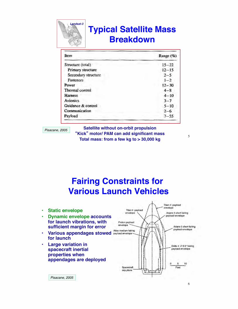
Response to Initial Condition
•! Lightly damped system has a decaying, oscillatory transient response
•! Forcing by step or impulse produces a similar transient response
! n = 6.28 rad/sec" = 0.05
21
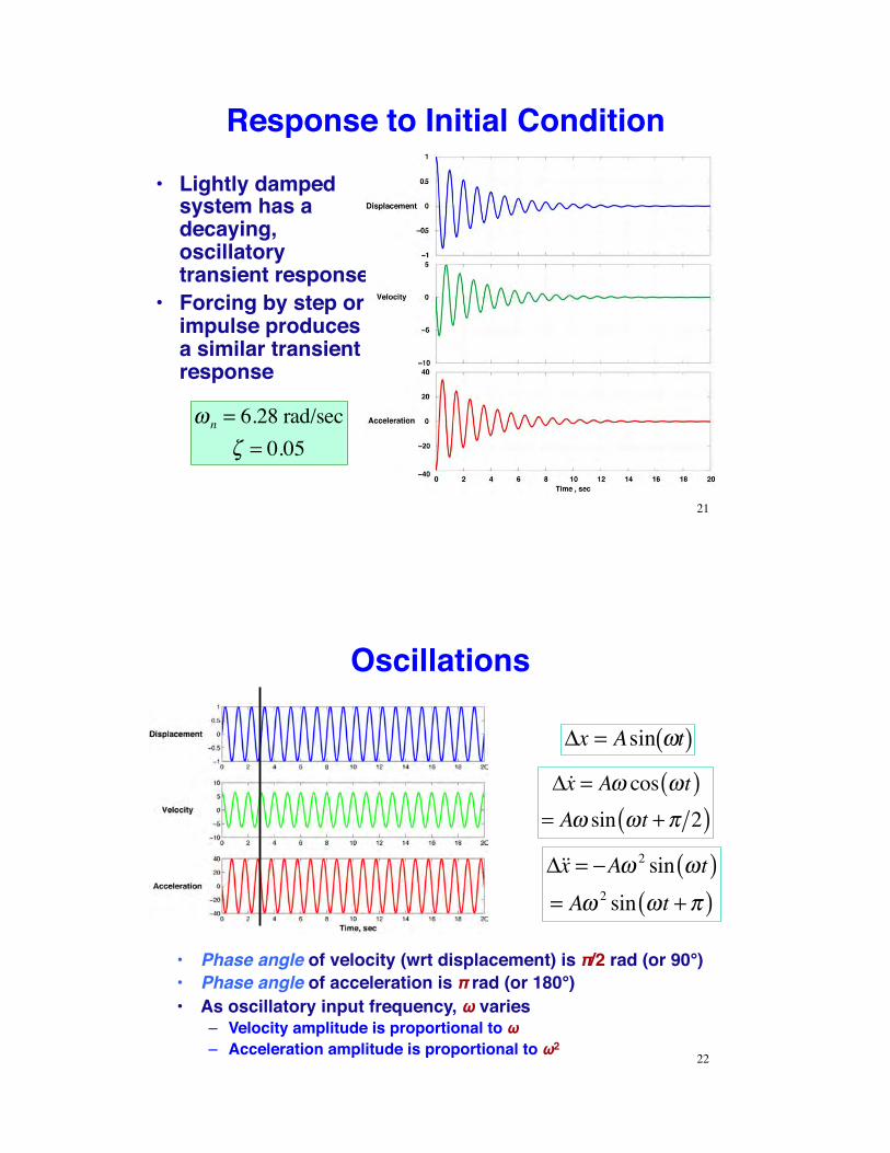
Oscillations
!x = Asin "t( )
!!x = A" cos "t( )= A" sin "t +# 2( )
!!!x = "A# 2 sin #t( )= A# 2 sin #t +$( )
•! Phase angle of velocity (wrt displacement) is $/2 rad (or 90°)•! Phase angle of acceleration is $ rad (or 180°)•! As oscillatory input frequency, % varies
–! Velocity amplitude is proportional to %–! Acceleration amplitude is proportional to %2
22

Response to Oscillatory Input
Compute Laplace transform to find transfer function
L !x(t)[ ] = !x(s) = !x(t)e" st dt0
#
$ ,
s =% + j& , ( j = i = "1)
L !!x(t)[ ] = s!x(s)L !!!x(t)[ ] = s2!x(s)
Neglecting initial conditions
23
Transfer Function
or L !!!x + 2"# n!!x +# n
2!x( ) = L # n2!u( )
s2 + 2!"ns+ "n2( )#x(s) = "n
2#u(s)
Transfer function from input to displacement
!x(s)!u(s)
= "n2
s2 + 2#"ns+ "n2( )
24
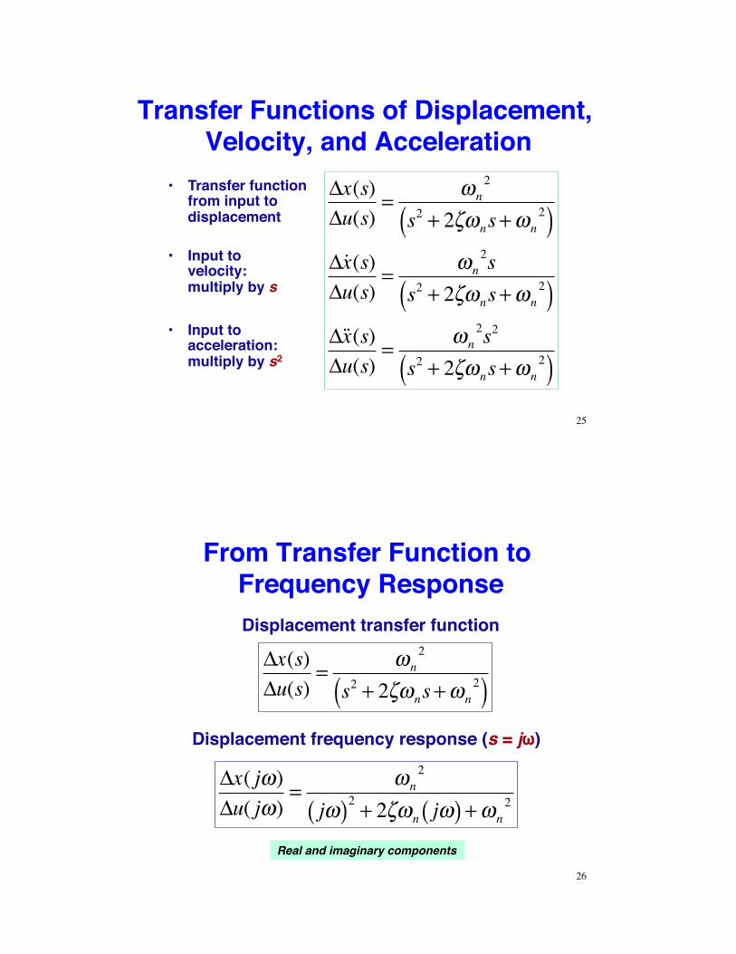
Transfer Functions of Displacement, Velocity, and Acceleration
!x(s)!u(s)
= "n2
s2 + 2#"ns + "n2( )
!˙ x (s)!u(s)
= "n2s
s2 + 2#"ns + "n2( )
!˙ ̇ x (s)!u(s)
= "n2s2
s2 + 2#"ns + "n2( )
•! Input to velocity: multiply by s
•! Input to acceleration: multiply by s2
•! Transfer function from input to displacement
25
From Transfer Function to Frequency Response
Displacement frequency response (s = j#)
!x( j")!u( j")
= "n2
j"( )2 + 2#"n j"( ) + "n2
!x(s)!u(s)
= "n2
s2 + 2#"ns+ "n2( )
Displacement transfer function
Real and imaginary components
26
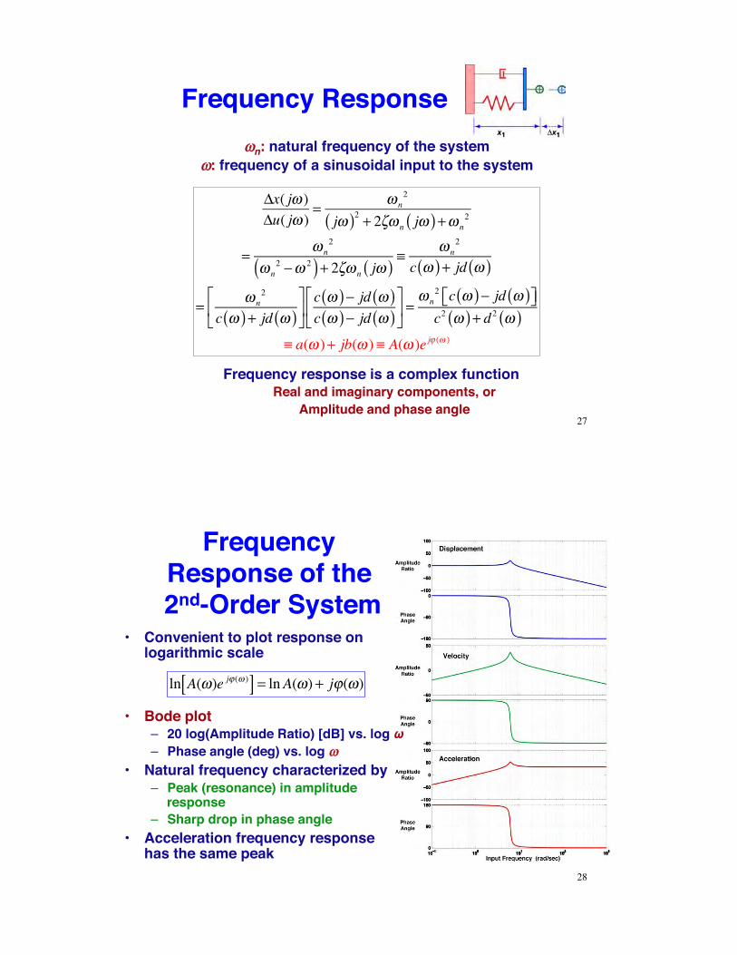
Frequency Response!!n: natural frequency of the system
!!: frequency of a sinusoidal input to the system
!x( j" )!u( j" )
= " n2
j"( )2 + 2#" n j"( ) +" n2
= " n2
" n2 $" 2( ) + 2#" n j"( ) %
" n2
c "( ) + jd "( )
= " n2
c "( ) + jd "( )&
'(
)
*+c "( )$ jd "( )c "( )$ jd "( )
&
'(
)
*+ =
" n2 c "( )$ jd "( )&' )*c2 "( ) + d 2 "( )
% a(" )+ jb(" ) % A(" )e j, (" )
Frequency response is a complex functionReal and imaginary components, or
Amplitude and phase angle27
Frequency Response of the 2nd-Order System
•! Convenient to plot response on logarithmic scale
ln A(!)e j" (! )[ ] = lnA(!) + j"(!)
28
•! Bode plot–! 20 log(Amplitude Ratio) [dB] vs. log %–! Phase angle (deg) vs. log !!
•! Natural frequency characterized by–! Peak (resonance) in amplitude
response–! Sharp drop in phase angle
•! Acceleration frequency response has the same peak

Acceleration Response of the 2nd-Order System
•! Important points:–! Low-frequency acceleration
response is attenuated–! Sinusoidal inputs at natural
frequency resonate, I.e., they are amplified
–! Component natural frequencies should be high enough to minimize likelihood of resonant response
29
Spacecraft Stiffness* Requirements for Primary Structure
* Natural frequency30

Typical Spacecraft Layout •! Atlas IIAS launch vehicle•! Spacecraft structure meets
primary stiffness requirements
•! What are axial stiffness requirements for Units A and B?–! Support deck natural
frequency = 50 Hz
Octave Rule: Component natural frequency & 2 x
natural frequency of supporting structure
Unit A: 2 x 15 Hz = 30 Hz, supported by primary structureUnit B: 2 x 50 Hz = 100 Hz, supported by secondary structure
31
Pisacane, 2005
Factors and Margins of SafetyFactor of Safety
Typical values: 1.25 to 1.4
Allowable load (yield stress)Expected limit load (stress)!Design factor of safety
"1
Margin of Safetythe amount of margin that exists above the material allowables for the applied loading
condition (with the factor of safety included)Skullney, Ch. 8, Pisacane, 2005
Load (stress) that causes yield or failureExpected service load
32

Worst-Case Axial Stress on a Simple Beam
Axial stress due to bending
! = My I
! =M h /2( )
I
Maximum stress
Worst-case axial stress due to bending and axial force
!wc = ± PA
" # $
% & ' max
±M h /2( )
I33
Pisacane, 2005
Stress on Spacecraft Adapter
•! Spacecraft weight = 500 lb•! Atlas IIAS launch vehicle•! Factor of safety = 1.25•! Maximum stress on
spacecraft adapter?
Atlas IIAS Limit Loads (g)
34
Pisacane, 2005

Example, con t.
Worst-case axial load at BECO (5±0.5 g)
!wc = ± PA
" # $
% & ' max
± McI
A = 2!rt = 7.1 in2
I = !r3t = 286 in4
Worst-case stress
! wc =500 " 5.57.1
+ 500 " 0.5 " 42 " 9286
#$%
&'("1.25 = 897.1 psi
Worst-case lateral load at BECO (2.5 ± 1 g) or Maximum Flight Winds (2.7 ± 0.8 g)
! wc =500 " 3.57.1
+ 500 " 2 " 42 " 9286
#$%
&'("1.25 = 1960 psi
35
Force and Moments on a Slender Cantilever (Fixed-Free) Beam
•! Idealization of –! Launch vehicle tied-down to a
launch pad–! Structural member of a
payload•! For a point force
–! Force and moment must be opposed at the base
–! Shear distribution is constant–! Bending moment increases as
moment arm increases–! Torsional moment and moment
arm are fixed36

Structural Stiffness•! Geometric stiffening property of a structure is
portrayed by the area moment of inertia•! For bending about a y axis (producing distortion along
an x axis)
•! Area moment of inertia for simple cross-sectional shapes
•! Solid rectangle of height, h, and width, w:
•! Solid circle of radius, r:
•! Circular cylindrical tube with inner radius, ri: and outer radius, ro:
Iy = wh3 /12
Iy = !r4 /4
Iy = ! ro4 " ri
4( ) /4
Ix = x z( )z2 dzzmin
zmax
!
37
Bending Stiffness•! Neutral axis neither shrinks nor stretches in bending•! For small deflections, the bending radius of
curvature of the neutral axis is
r = EIM
•! Deflection at a point characterized by displacement and angle:
38

Bending Deflection
Second derivative of z and first derivative of "" are inversely proportional to the bending radius:
d2zdx 2
= d!dx
=My
EIy39
Maximum Deflection and Bending Moment of Beams!
(see Fundamentals of Space Systems for additional cases)
Fixed-Free Beam Fixed-Fixed Beam Pinned-Pinned Beam
Ymax = maximum deflection Mmax = maximum bending moment
40Pisacane, 2005
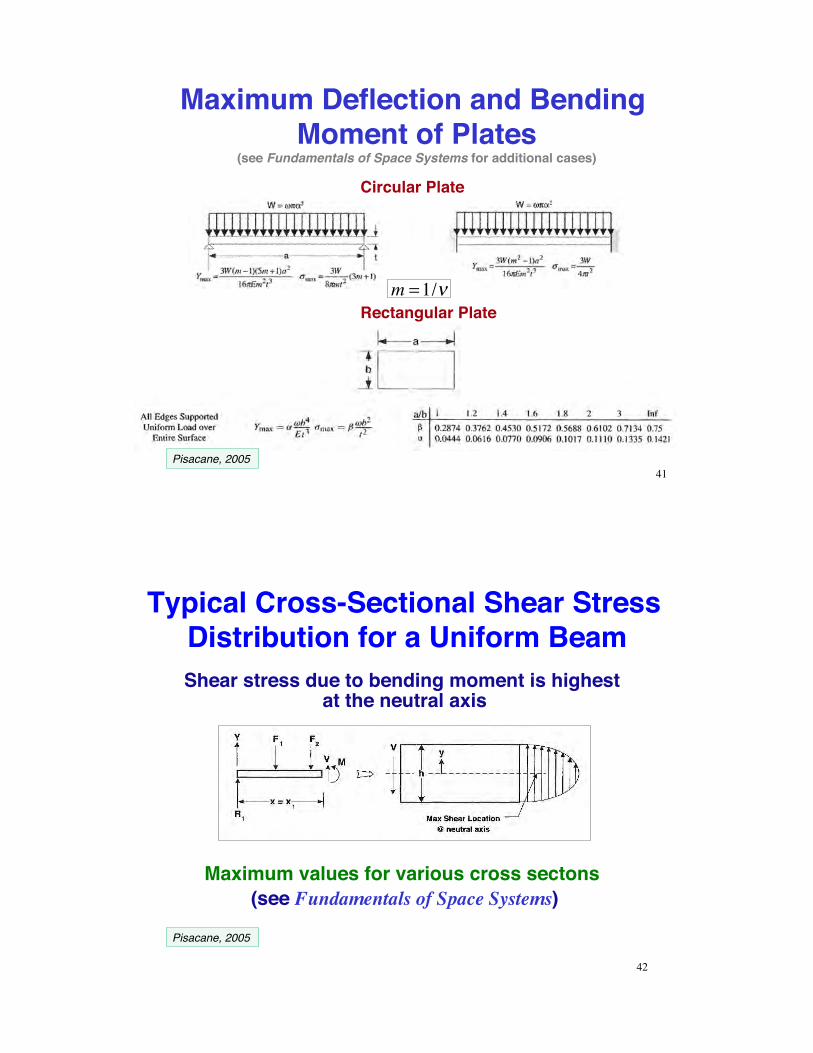
Maximum Deflection and Bending Moment of Plates!
(see Fundamentals of Space Systems for additional cases)
Circular Plate
Rectangular Plate
m =1/!
41Pisacane, 2005
Typical Cross-Sectional Shear Stress Distribution for a Uniform BeamShear stress due to bending moment is highest
at the neutral axis
Maximum values for various cross sectons (see Fundamentals of Space Systems)
42
Pisacane, 2005

Buckling
•! Predominant steady stress during launch is compression
•! Thin columns, plates, and shells are subject to elastic instability in compression
•! Buckling can occur below the material s elastic limit
! cr = C" 2EL /#( )2
= PA
Critical buckling stress of a column (Euler equation)
C = function of end "fixity"E = modulus of elasticity
L = column length
! = I A = radius of gyrationPcr = critical buckling loadA = cross sectional area 43
Effect of Fixity on Critical Loads for Beam Buckling
•! Euler equation–! Slender columns–! Critical stress below the
elastic limit–! Relatively thick column
walls•! Local collapse due to thin
walls is called crippling
Crippling vs. Buckling
44
Pisacane, 2005

45
Critical Stress for Plate and Cylinder Buckling
Pisacane, 2005
Deflection is found by four integrations of the deflection equation
d2
dx 2EIy
d2zdx 2
!
" #
$
% & x= xs
= N 'y xs( )
N y(xs)
My x( ) = Ny(x)xmin
xmax
! x " xcm( )dx
= N 'y(x)xmin
xmax
! dx x " xcm( )dxxmin
xmax
!N '(x) = normal force variation with length
46
Bending Moment and Linear Deflection due to a Distributed Normal Force

Bending Vibrations of a Free-Free Uniform Beam
EIyd4zdx 4 x= xs
= k = !m' d2zdt 2 x= xs
EIy = constantm' =mass variation with length (constant)
k = effective spring constant
Solution by separation of variables requires that left and right sides equal a constant, k
An infinite number of separation constants, ki, existTherefore, there are an infinite number of vibrational
response modes47
Bending Vibrations of a Free-Free Uniform Beam
•! In figure, (u = z, y = x)•! Left side determines
vibrational mode shape•! Right side describes
oscillation•! Natural frequency of
each mode proportional to (ki)1/2
Mode shapes of bending vibrations
EIyd4zdx 4
= ki = !m' d2zdt 2
48

Fundamental Vibrational Frequencies of Circular Plates
f = natural frequency of first mode, Hz
49Pisacane, 2005
Vibrational Mode Shapes for the X-30 (NASP)
Vehicle Computational Grid for Finite-
Element Model
Body elastic deflection distorts the shape of scramjet inlet and exhaust ramps
Aeroelastic-propulsive interactionsImpact on flight dynamics
Shapes of the First Seven Modes
50
Raney, J. Aircraft, 1995

Pogo Oscillation!! Longitudinal resonance of launch vehicle structure
!! Flexing of the propellant-feed pipes induces thrust variation in liquid-propellant rocket
!! Gas-filled cavities added to the pipes, damping oscillation
!! “Organ-pipe” oscillation in Space Shuttle Solid Rocket Booster!! 15-Hz resonance in 4-segment motor!! 12-Hz resonance in 5-segment motor
51Pogo oscillation http://history.nasa.gov/SP-4205/ch10-6.html
Fuel Slosh!! Lateral motion of liquid propellant in partially empty
tank induces inertial forces!! Resonance with flight motions!! Problem reduced by baffling
52http://en.wikipedia.org/wiki/Space_Shuttle_external_tank
Space Shuttle External Tank

Thermal Stresses•! Direct weakening of
material by high temperature, e.g., effect of aerodynamic heating
•! Embrittlement of metals at low temperature
•! Internal stress caused by differential temperatures, e.g., on common bulkhead between hydrogen and oxygen tanks
53
Temperature ofLiquid Hydrogen: 20.3 K (–253°C)Liquid Oxygen: 50.5 K (–223°C)
Fracture and Fatigue Failure from Repeated/Oscillatory Loading
54
!! Cyclic loading produces cracks!! Fatigue life: # of loading cycles
before failure occurs
Miner’s rule, Paris’s law, Goodman relation, …

Finite-Element Structural Model
55
!! Grid of elements, each with!! Mass, damping, and elastic properties!! 6 degrees of freedom at each node
!! Static and dynamic analysis
see Pisacane (Skullney), Sec 8.15
Types of Finite Element
56
Fortescue, 2011
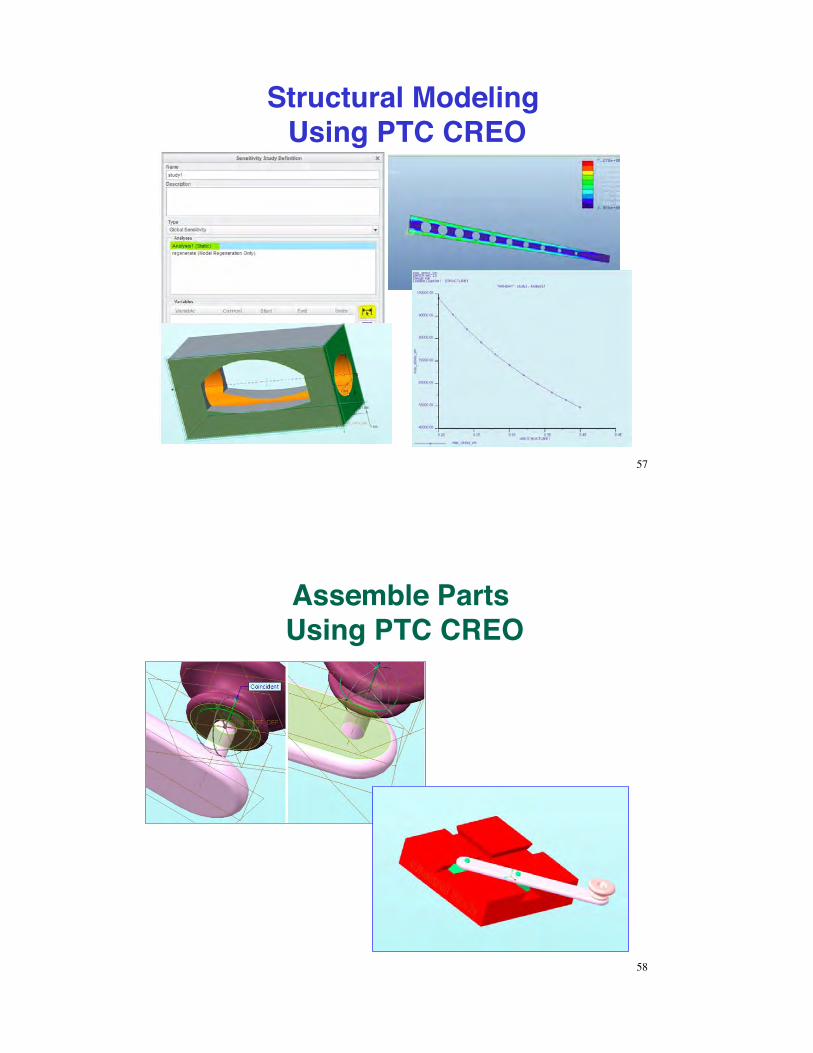
Structural Modeling Using PTC CREO
57
Assemble Parts Using PTC CREO
58

Analyze Loads Using PTC CREO
59
http://learningexchange.ptc.com/tutorial/799/creating-a-buckling-analysis
Next Time:!Spacecraft Configurations!
60