Embed Size (px)
Citation preview
Optical configuration 21
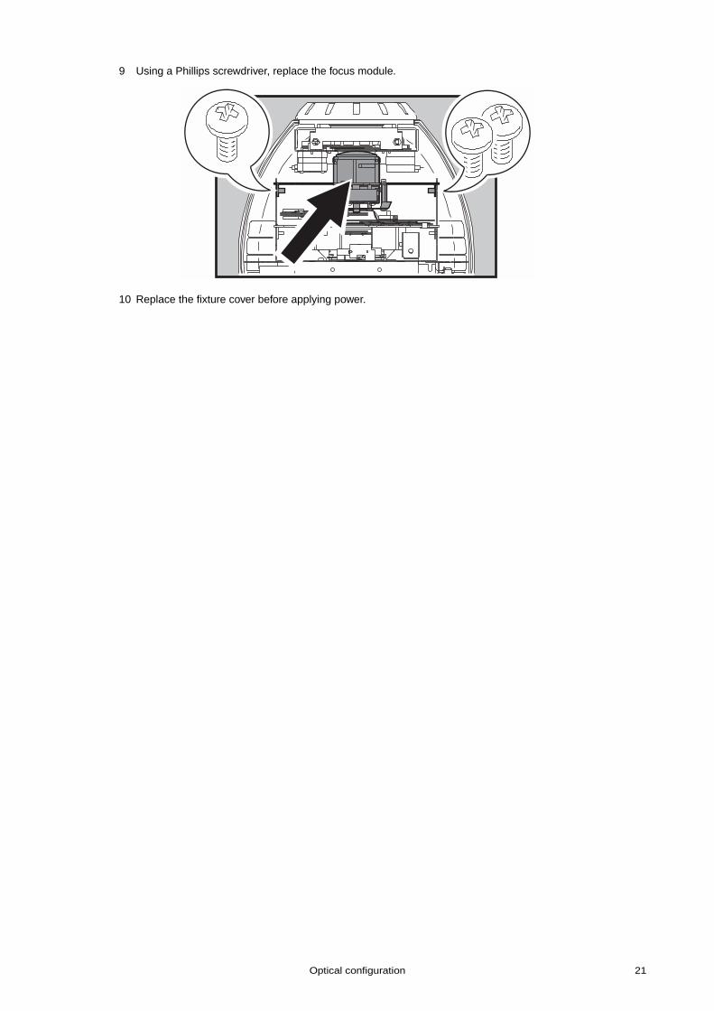
9 Using a Phillips screwdriver, replace the focus module.
10 Replace the fixture cover before applying power.
22 CX-10
Animation wheels
An animation wheel can replace, or be affixed to the color wheel. This requires an Animation Wheel AdaptorKit and an animation disc (see “Accessories” on page 41).
For a list of currently available animation wheels and tips on what effects are possible, see “Animationwheels and their uses” below. To achieve many effects you will use both an animation wheel and a regulargobo (and potentially a color filter) installed on the effect wheel.
To install an animation wheel, see:
• “Affixing an animation wheel to the color wheel” on page 24, below, or• “Replacing the color wheel with an animation wheel” on page 26
A N I M A T I O N W H E E L S A N D T H E I R U S E S
The animation wheels mentioned here can be ordered from your Martin dealer. The effects described aremerely suggestions and a degree of experimentation may be required to achieve exactly the effect that youwant to achieve. You may need to align the whole fixture along another plane in order to achieve animatedvertical or horizontal motion.
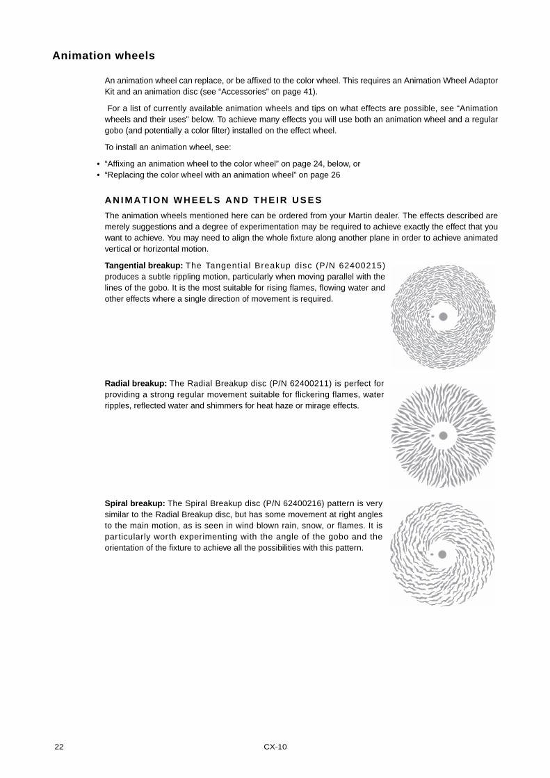
Tangential breakup: The Tangent ial Breakup disc (P/N 62400215)produces a subtle rippling motion, particularly when moving parallel with thelines of the gobo. It is the most suitable for rising flames, flowing water andother effects where a single direction of movement is required.
Radial breakup: The Radial Breakup disc (P/N 62400211) is perfect forproviding a strong regular movement suitable for flickering flames, waterripples, reflected water and shimmers for heat haze or mirage effects.
Spiral breakup: The Spiral Breakup disc (P/N 62400216) pattern is verysimilar to the Radial Breakup disc, but has some movement at right anglesto the main motion, as is seen in wind blown rain, snow, or flames. It isparticularly worth experimenting with the angle of the gobo and theorientation of the fixture to achieve all the possibilities with this pattern.
Optical configuration 23
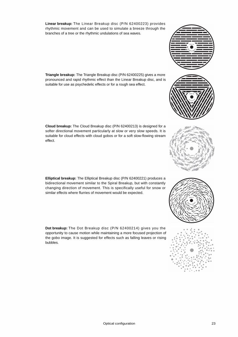
Linear breakup: The Linear Breakup disc (P/N 62400223) providesrhythmic movement and can be used to simulate a breeze through thebranches of a tree or the rhythmic undulations of sea waves.
Triangle breakup: The Triangle Breakup disc (P/N 62400225) gives a morepronounced and rapid rhythmic effect than the Linear Breakup disc, and issuitable for use as psychedelic effects or for a rough sea effect.
Cloud breakup: The Cloud Breakup disc (P/N 62400213) is designed for asofter directional movement particularly at slow or very slow speeds. It issuitable for cloud effects with cloud gobos or for a soft slow-flowing streameffect.
Elliptical breakup: The Elliptical Breakup disc (P/N 62400221) produces abidirectional movement similar to the Spiral Breakup, but with constantlychanging direction of movement. This is specifically useful for snow orsimilar effects where flurries of movement would be expected.
Dot breakup: The Dot Breakup disc (P/N 62400214) gives you theopportunity to cause motion while maintaining a more focused projection ofthe gobo image. It is suggested for effects such as falling leaves or risingbubbles.
DHA 14
MARTIN 080302
DHA 15
M
ARTIN 080302/
DHA 17
MARTIN 080302
24 CX-10
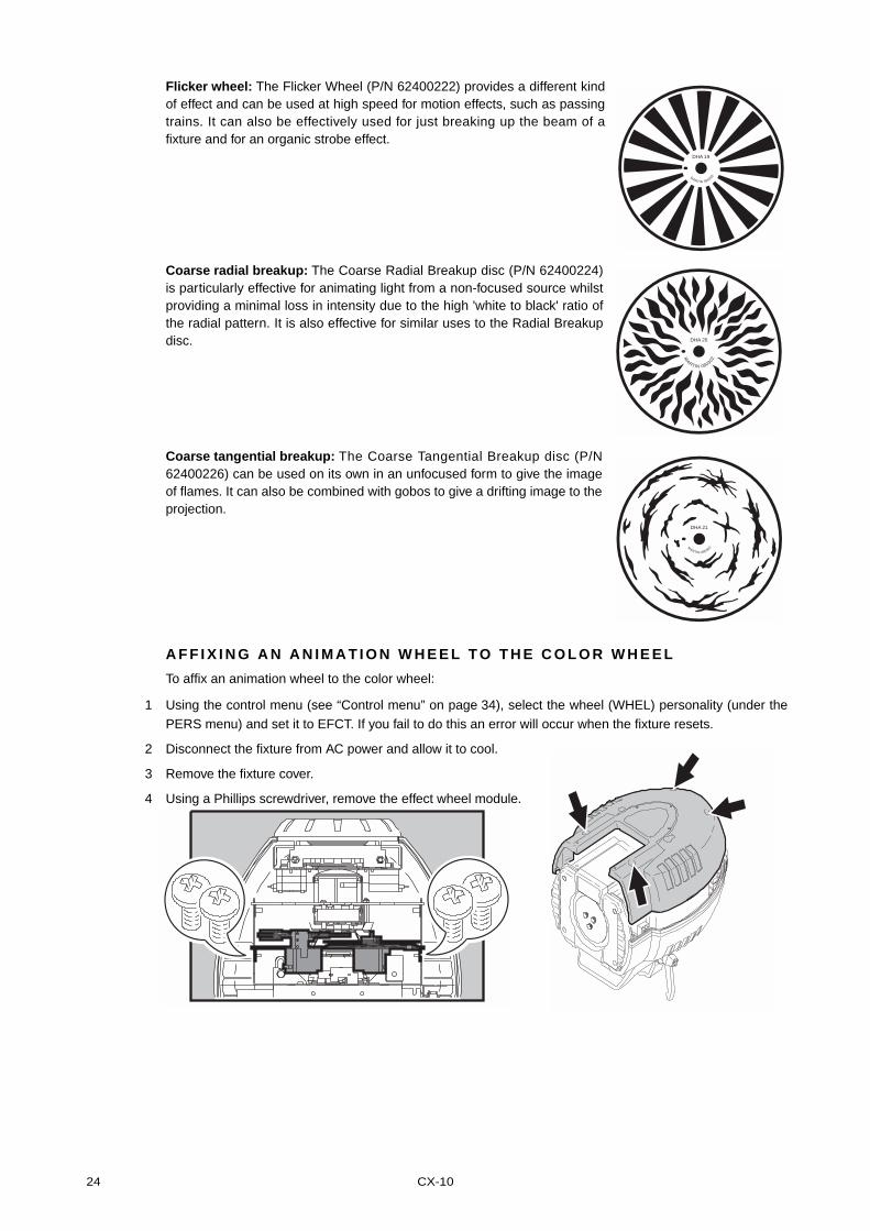
Flicker wheel: The Flicker Wheel (P/N 62400222) provides a different kindof effect and can be used at high speed for motion effects, such as passingtrains. It can also be effectively used for just breaking up the beam of afixture and for an organic strobe effect.
Coarse radial breakup: The Coarse Radial Breakup disc (P/N 62400224)is particularly effective for animating light from a non-focused source whilstproviding a minimal loss in intensity due to the high 'white to black' ratio ofthe radial pattern. It is also effective for similar uses to the Radial Breakupdisc.
Coarse tangential breakup: The Coarse Tangential Breakup disc (P/N62400226) can be used on its own in an unfocused form to give the imageof flames. It can also be combined with gobos to give a drifting image to theprojection.
A F F I X I N G A N A N I M A T I O N W H E E L T O T H E C O L O R W H E E L
To affix an animation wheel to the color wheel:
1 Using the control menu (see “Control menu” on page 34), select the wheel (WHEL) personality (under the
PERS menu) and set it to EFCT. If you fail to do this an error will occur when the fixture resets.
2 Disconnect the fixture from AC power and allow it to cool.
3 Remove the fixture cover.
4 Using a Phillips screwdriver, remove the effect wheel module.
DHA 19
MARTIN 080302
DHA 20
MARTIN 080302
DHA 21
M
ARTIN 080302
Optical configuration 25
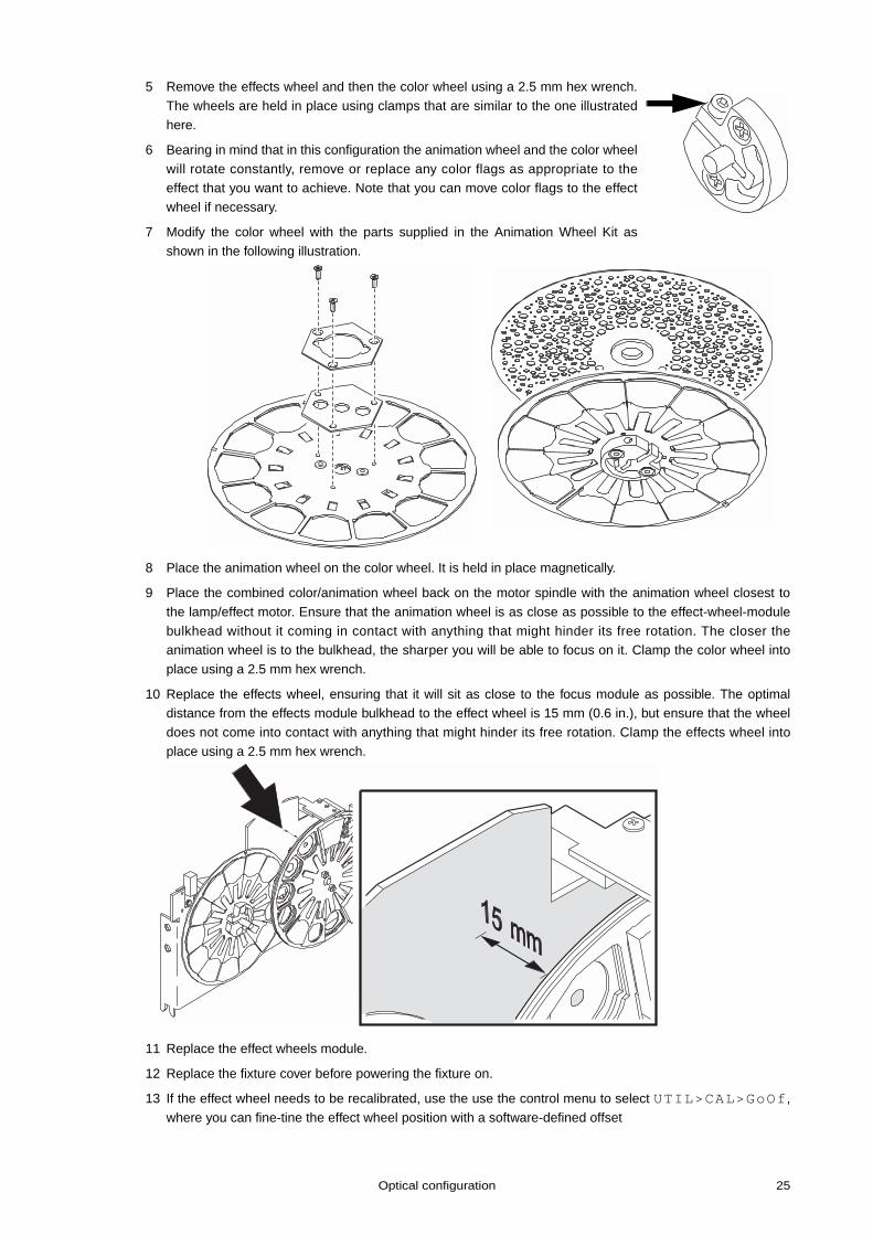
5 Remove the effects wheel and then the color wheel using a 2.5 mm hex wrench.
The wheels are held in place using clamps that are similar to the one illustrated
here.
6 Bearing in mind that in this configuration the animation wheel and the color wheel
will rotate constantly, remove or replace any color flags as appropriate to theeffect that you want to achieve. Note that you can move color flags to the effect
wheel if necessary.
7 Modify the color wheel with the parts supplied in the Animation Wheel Kit as
shown in the following illustration.
8 Place the animation wheel on the color wheel. It is held in place magnetically.
9 Place the combined color/animation wheel back on the motor spindle with the animation wheel closest to
the lamp/effect motor. Ensure that the animation wheel is as close as possible to the effect-wheel-module
bulkhead without it coming in contact with anything that might hinder its free rotation. The closer theanimation wheel is to the bulkhead, the sharper you will be able to focus on it. Clamp the color wheel into
place using a 2.5 mm hex wrench.
10 Replace the effects wheel, ensuring that it will sit as close to the focus module as possible. The optimaldistance from the effects module bulkhead to the effect wheel is 15 mm (0.6 in.), but ensure that the wheel
does not come into contact with anything that might hinder its free rotation. Clamp the effects wheel into
place using a 2.5 mm hex wrench.
11 Replace the effect wheels module.
12 Replace the fixture cover before powering the fixture on.
13 If the effect wheel needs to be recalibrated, use the use the control menu to select UTIL>CAL>GoOf,
where you can fine-tine the effect wheel position with a software-defined offset
26 CX-10
Note: If at a later time you remove the animation wheel then use the control menu to select the wheel (WHEL) personality (under the PERS menu) and set it to COLR. When you reinstall the color wheel you may also need to calibrate it using the color wheel calibration option available under the Utility menu. See “Control menu” on page 34 for more information.
R E P L A C I N G T H E C O L O R W H E E L W I T H A N A N I M A T I O N W H E E L
To replace the color wheel with an animation wheel:
1 Using the control menu (see “Control menu” on page 34), select the wheel (WHEL) personality (under thePERS menu) and set it to EFCT. If you fail to do this an error will occur when the fixture resets.
2 Disconnect the fixture from AC power and allow it to cool.
3 Remove the fixture cover.
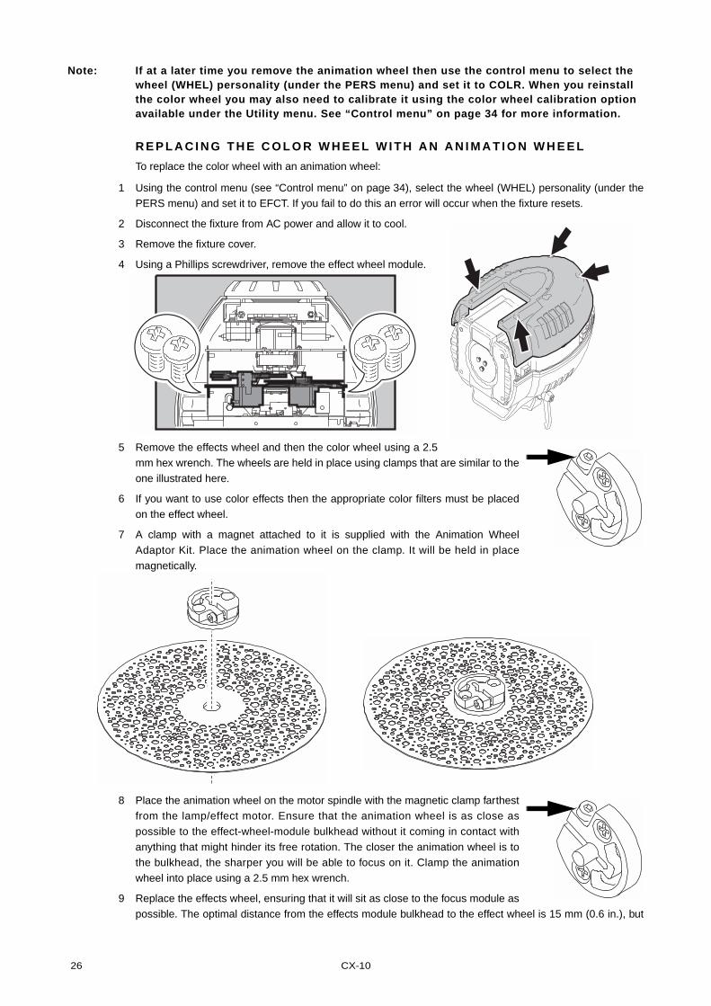
4 Using a Phillips screwdriver, remove the effect wheel module.
5 Remove the effects wheel and then the color wheel using a 2.5mm hex wrench. The wheels are held in place using clamps that are similar to the
one illustrated here.
6 If you want to use color effects then the appropriate color filters must be placed
on the effect wheel.
7 A clamp with a magnet attached to it is supplied with the Animation Wheel
Adaptor Kit. Place the animation wheel on the clamp. It will be held in place
magnetically.
8 Place the animation wheel on the motor spindle with the magnetic clamp farthestfrom the lamp/effect motor. Ensure that the animation wheel is as close as
possible to the effect-wheel-module bulkhead without it coming in contact with
anything that might hinder its free rotation. The closer the animation wheel is tothe bulkhead, the sharper you will be able to focus on it. Clamp the animation
wheel into place using a 2.5 mm hex wrench.
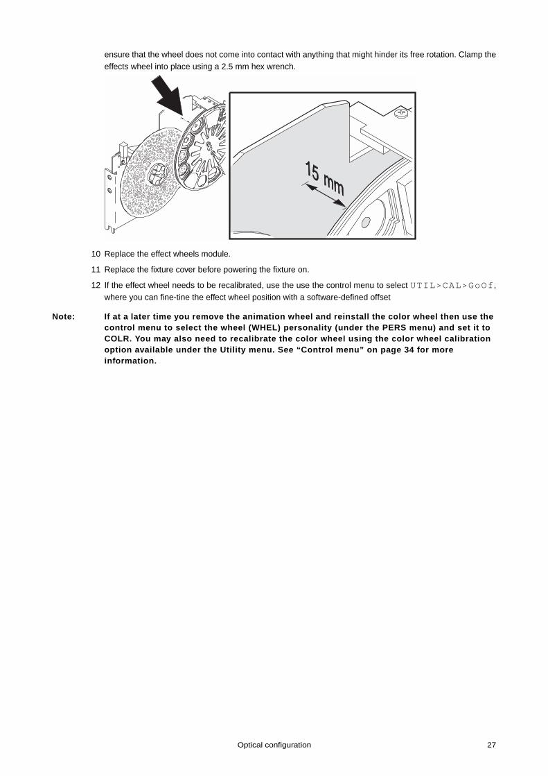
9 Replace the effects wheel, ensuring that it will sit as close to the focus module as
possible. The optimal distance from the effects module bulkhead to the effect wheel is 15 mm (0.6 in.), but
Optical configuration 27
ensure that the wheel does not come into contact with anything that might hinder its free rotation. Clamp the
effects wheel into place using a 2.5 mm hex wrench.
10 Replace the effect wheels module.
11 Replace the fixture cover before powering the fixture on.
12 If the effect wheel needs to be recalibrated, use the use the control menu to select UTIL>CAL>GoOf,
where you can fine-tine the effect wheel position with a software-defined offset
Note: If at a later time you remove the animation wheel and reinstall the color wheel then use the control menu to select the wheel (WHEL) personality (under the PERS menu) and set it to COLR. You may also need to recalibrate the color wheel using the color wheel calibration option available under the Utility menu. See “Control menu” on page 34 for more information.
28 CX-10
SERVICE
The CX-10 requires regular maintenance to keep performing at their peak. Excessive dust, grease, andsmoke fluid buildup degrades performance and causes overheating and damage that is not covered by thewarranty. The maintenance schedule will depend on the application and should be discussed with yourMartin distributor. Refer any service that is not described here to a professional technician.
Warning! Removing covers while the fixture is powered on exposes dangerous live electrical circuits, hot surfaces, and a lamp under high pressure. Disconnect the fixture from AC power and allow it to cool before removing any cover.
Lamp
Lamp life will vary; the rated life is an average figure that is based on the manufacturer’s test cycle. Formaximum lamp life, avoid excessive strikes and always allow the lamp to burn for at least 5 minutes beforeturning it off.
To reduce the risk of lamp explosion, which may damage the fixture, never exceed the lamp’s rated life(2000 hours) by more than 25 percent.
Replace the lamp when:
• it strikes with difficulty or not at all, or is in any other way defective• usage exceeds the manufacturer’s “replace before” hours. See Table 3.
C O M P A T I B L E L A M P S
A Philips MSD 250/2 lamp is included. The CX-10 lamp options are shown in the table below. Installing anyother lamp may damage the fixture.
Lamp Average life Replace before Color Temp. Output P/N
Osram HSD 250 2000 hr 2500 hr 6000K 68 lm/W 97010103
Philips MSD 250/2 2000 hr 2200 hr 6500K 72 lm/W 97010100
Philips MSD 200 2000 hr 2200 hr 5600K 67 lm/W 97010106
Table 3: Lamp comparison
Service 29
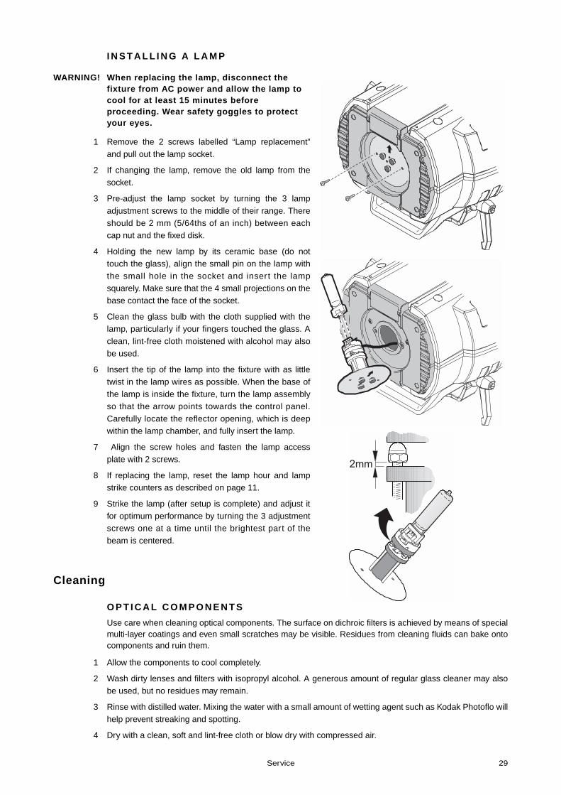
I N S T A L L I N G A L A M P
WARNING! When replacing the lamp, disconnect the fixture from AC power and allow the lamp to cool for at least 15 minutes before proceeding. Wear safety goggles to protect your eyes.
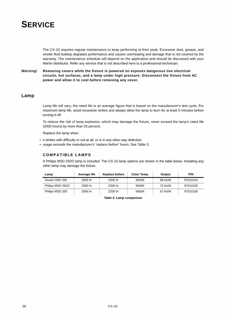
1 Remove the 2 screws labelled “Lamp replacement”
and pull out the lamp socket.
2 If changing the lamp, remove the old lamp from the
socket.
3 Pre-adjust the lamp socket by turning the 3 lamp
adjustment screws to the middle of their range. There
should be 2 mm (5/64ths of an inch) between eachcap nut and the fixed disk.
4 Holding the new lamp by its ceramic base (do nottouch the glass), align the small pin on the lamp with
the small hole in the socket and insert the lamp
squarely. Make sure that the 4 small projections on thebase contact the face of the socket.
5 Clean the glass bulb with the cloth supplied with thelamp, particularly if your fingers touched the glass. A
clean, lint-free cloth moistened with alcohol may also
be used.
6 Insert the tip of the lamp into the fixture with as little
twist in the lamp wires as possible. When the base ofthe lamp is inside the fixture, turn the lamp assembly
so that the arrow points towards the control panel.
Carefully locate the reflector opening, which is deepwithin the lamp chamber, and fully insert the lamp.
7 Align the screw holes and fasten the lamp accessplate with 2 screws.
8 If replacing the lamp, reset the lamp hour and lampstrike counters as described on page 11.
9 Strike the lamp (after setup is complete) and adjust itfor optimum performance by turning the 3 adjustment
screws one at a time until the brightest part of the
beam is centered.
Cleaning
O P T I C A L C O M P O N E N T S
Use care when cleaning optical components. The surface on dichroic filters is achieved by means of specialmulti-layer coatings and even small scratches may be visible. Residues from cleaning fluids can bake ontocomponents and ruin them.
1 Allow the components to cool completely.
2 Wash dirty lenses and filters with isopropyl alcohol. A generous amount of regular glass cleaner may also
be used, but no residues may remain.
3 Rinse with distilled water. Mixing the water with a small amount of wetting agent such as Kodak Photoflo will
help prevent streaking and spotting.
4 Dry with a clean, soft and lint-free cloth or blow dry with compressed air.
2mm
30 CX-10
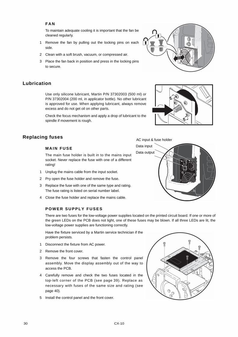
F A N
To maintain adequate cooling it is important that the fan becleaned regularly.
1 Remove the fan by pulling out the locking pins on eachside.
2 Clean with a soft brush, vacuum, or compressed air.
3 Place the fan back in position and press in the locking pins
to secure.
Lubrication
Use only silicone lubricant, Martin P/N 37302003 (500 ml) orP/N 37302004 (200 ml, in applicator bottle). No other lubricantis approved for use. When applying lubricant, always removeexcess and do not get oil on other parts.
Check the focus mechanism and apply a drop of lubricant to thespindle if movement is rough.
Replacing fuses
M A I N F U S E
The main fuse holder is built in to the mains inputsocket. Never replace the fuse with one of a differentrating!
1 Unplug the mains cable from the input socket.
2 Pry open the fuse holder and remove the fuse.
3 Replace the fuse with one of the same type and rating.
The fuse rating is listed on serial number label.
4 Close the fuse holder and replace the mains cable.
P O W E R S U P P L Y F U S E S
There are two fuses for the low-voltage power supplies located on the printed circuit board. If one or more ofthe green LEDs on the PCB does not light, one of these fuses may be blown. If all three LEDs are lit, thelow-voltage power supplies are functioning correctly.
Have the fixture serviced by a Martin service technician if theproblem persists.
1 Disconnect the fixture from AC power.
2 Remove the front cover.
3 Remove the four screws that fasten the control panelassembly. Move the display assembly out of the way to
access the PCB.
4 Carefully remove and check the two fuses located in the
top-left corner of the PCB (see page 39). Replace as
necessary with fuses of the same size and rating (see
page 40).
5 Install the control panel and the front cover.
AC input & fuse holder
Data input
Data output
Service 31
Updating software
The latest CX-10 f i rmware is ava i lable f rom the suppor t area of the Mar t in web s i te a thttp://www.martin.com. It can be installed using an MP-2, or via a PC serial data link using a hardwareinterface supported by the Software Uploader shareware (also available from the Martin web site). Thefollowing devices are currently supported (in Version 5.5):
• DABS 1 (presently available with the MUM software package)• ShowDesigner PCI DMX Interface Card (2048 channel version)• LightJockey PCI DMX Interface Card (512 and 2048 channel versions)• LightJockey PCMCIA DMX Interface• LightJockey 4064 ISA DMX Interface Card (DJ and Club versions)
Note: Intermediate control systems such as the Martin Lighting Director (MLD) and the Martin Matrix mustbe bypassed when updating fixture software via the DMX link. These systems do not relay the update codecorrectly because it is not a DMX-compliant signal.
N O R M A L U P D A T E
To update fixture software, connect an upload device to the fixture just like a DMX controller and perform aDMX mode upload as described in the uploader’s documentation. There is no need to isolate the CX-10sfrom other types of fixtures on the serial link.
When the upload is completed (and when booting up) the CX-10 performs a check-sum test of the flashmemory and then resets. If the firmware is corrupted a check-sum error (CSER ) occurs. A few secondslater the fixture displays UPLd and is ready for a new DMX-mode upload.
In the unlikely event that a software upload is interrupted, the fixture must be powered off for at least 10seconds to force the check-sum test. You can repeat the DMX-mode upload as soon as UPLd is displayed.
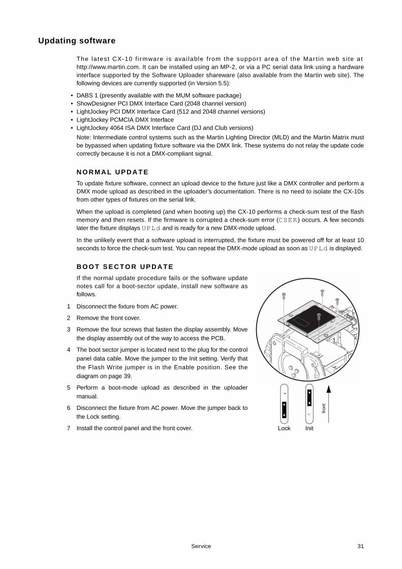
B O O T S E C T O R U P D A T E
If the normal update procedure fails or the software updatenotes call for a boot-sector update, install new software asfollows.
1 Disconnect the fixture from AC power.
2 Remove the front cover.
3 Remove the four screws that fasten the display assembly. Move
the display assembly out of the way to access the PCB.
4 The boot sector jumper is located next to the plug for the control
panel data cable. Move the jumper to the Init setting. Verify thatthe Flash Write jumper is in the Enable position. See the
diagram on page 39.
5 Perform a boot-mode upload as described in the uploader
manual.
6 Disconnect the fixture from AC power. Move the jumper back to
the Lock setting.
7 Install the control panel and the front cover. InitLock
fron
t
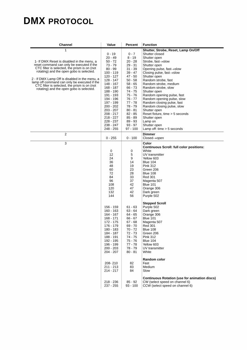
DMX PROTOCOL
Channel Value Percent Function
1
1- If DMX Reset is disabled in the menu, a reset command can only be executed if the CTC filter is selected, the prism is on (not rotating) and the open gobo is selected.
2 - If DMX Lamp Off is disabled in the menu, a lamp off command can only be executed if the
CTC filter is selected, the prism is on (not rotating) and the open gobo is selected.
0 - 19
20 - 4950 - 7273 - 7980 - 99
100 - 119120 - 127128 - 147148 - 167168 - 187188 - 190191 - 193194 - 196197 - 199200 - 202203 - 207208 - 217218 - 227228 - 237238 - 247248 - 255
0 - 78 - 19
20 - 2829 - 3131 - 3939 - 4747 - 5050 - 5858 - 6566 - 7374 - 7575 - 7676 - 7777 - 7878 - 7980 - 8182 - 8585 - 8989 - 9393 - 97
97 - 100
Shutter, Strobe, Reset, Lamp On/OffShutter closedShutter openStrobe, fast→slowShutter openOpening pulse, fast→slowClosing pulse, fast→slowShutter openRandom strobe, fastRandom strobe, mediumRandom strobe, slowShutter openRandom opening pulse, fastRandom opening pulse, slowRandom closing pulse, fastRandom closing pulse, slowShutter openReset fixture, time > 5 secondsShutter openLamp on Shutter openLamp off: time > 5 seconds
20 - 255 0 - 100
DimmerClosed→open
3
01224364860728496
108120132144
156 - 159160 - 163164 - 167168 - 171172 - 175176 - 179180 - 183184 - 187188 - 191192 - 195196 - 199200 - 203204 - 207
208- 210211 - 213214 - 217
218 - 236237 - 255
059
14192328333742474256
61 - 6363 - 6464 - 6566 - 6767 - 6869 - 7070 - 7272 - 7374 - 7575 - 7677 - 7878 - 7980 - 81
828384
85 - 9293 - 100
ColorContinuous Scroll: full color positions:WhiteUV transmitterYellow 603Blue 104Pink 312Green 206Blue 108Red 301Magenta 507Blue 101Orange 306Dark greenPurple 502
Stepped ScrollPurple 502Dark greenOrange 306Blue 101Magenta 507Red 301Blue 108Green 206Pink 312Blue 104Yellow 603UV transmitterWhite
Random colorFastMediumSlow
Continuous Rotation (use for animation discs)CW (select speed on channel 6)CCW (select speed on channel 6)
DMX protocol 33
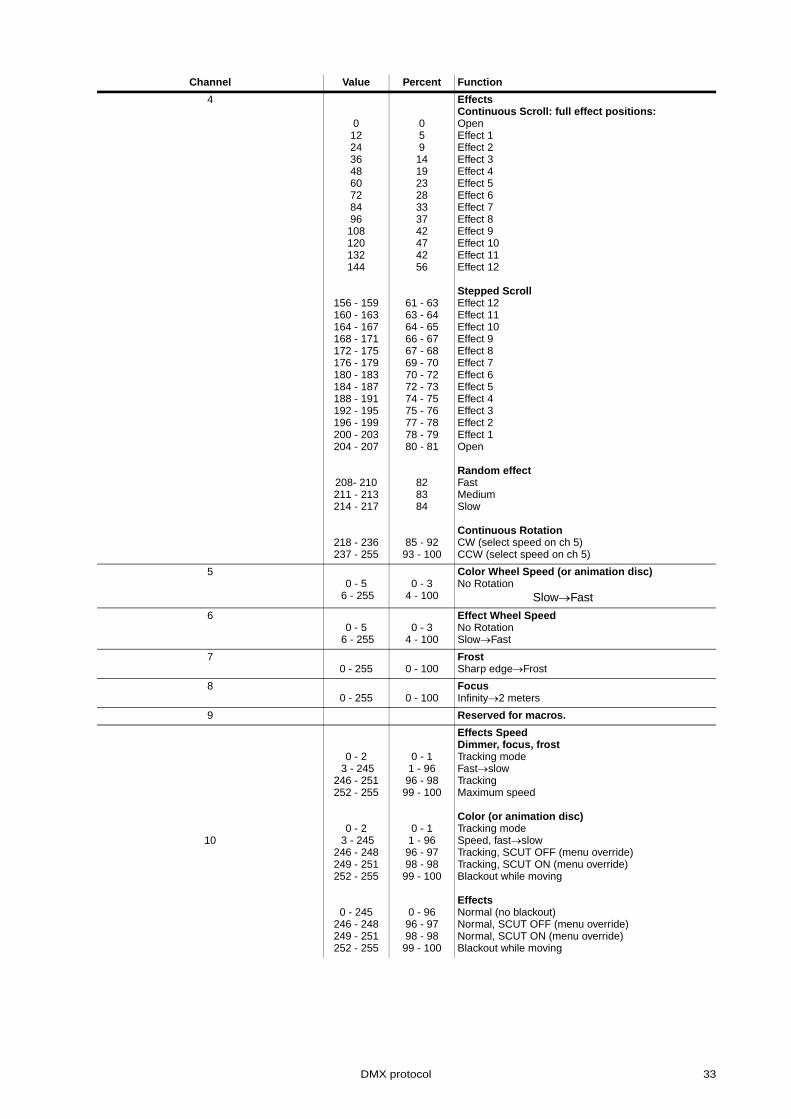
4
01224364860728496
108120132144
156 - 159160 - 163164 - 167168 - 171172 - 175176 - 179180 - 183184 - 187188 - 191192 - 195196 - 199200 - 203204 - 207
208- 210211 - 213214 - 217
218 - 236237 - 255
059
14192328333742474256
61 - 6363 - 6464 - 6566 - 6767 - 6869 - 7070 - 7272 - 7374 - 7575 - 7677 - 7878 - 7980 - 81
828384
85 - 9293 - 100
EffectsContinuous Scroll: full effect positions:OpenEffect 1Effect 2Effect 3Effect 4Effect 5Effect 6Effect 7Effect 8Effect 9Effect 10Effect 11Effect 12
Stepped ScrollEffect 12Effect 11Effect 10Effect 9Effect 8Effect 7Effect 6Effect 5Effect 4Effect 3Effect 2Effect 1Open
Random effectFastMediumSlow
Continuous RotationCW (select speed on ch 5)CCW (select speed on ch 5)
50 - 5
6 - 2550 - 3
4 - 100
Color Wheel Speed (or animation disc)No Rotation
Slow→Fast
60 - 5
6 - 2550 - 3
4 - 100
Effect Wheel SpeedNo RotationSlow→Fast
7 0 - 255 0 - 100
FrostSharp edge→Frost
8 0 - 255 0 - 100
FocusInfinity→2 meters
9 Reserved for macros.
10
0 - 2 3 - 245
246 - 251252 - 255
0 - 2 3 - 245
246 - 248249 - 251252 - 255
0 - 245246 - 248249 - 251252 - 255
0 - 11 - 96
96 - 9899 - 100
0 - 11 - 96
96 - 9798 - 98
99 - 100
0 - 9696 - 9798 - 98
99 - 100
Effects SpeedDimmer, focus, frostTracking modeFast→slowTrackingMaximum speed
Color (or animation disc)Tracking modeSpeed, fast→slowTracking, SCUT OFF (menu override)Tracking, SCUT ON (menu override)Blackout while moving
EffectsNormal (no blackout)Normal, SCUT OFF (menu override)Normal, SCUT ON (menu override)Blackout while moving
Channel Value Percent Function
34 CX-10
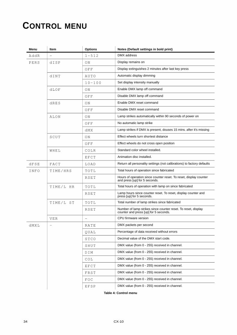
CONTROL MENU
Menu Item Options Notes (Default settings in bold print)
AddR - 1-512 DMX address
PERS dISP ON Display remains on
OFF Display extinguishes 2 minutes after last key press
dINT AUTO Automatic display dimming
10-100 Set display intensity manually
dLOF ON Enable DMX lamp off command
OFF Disable DMX lamp off command
dRES ON Enable DMX reset command
OFF Disable DMX reset command
ALON ON Lamp strikes automatically within 90 seconds of power on
OFF No automatic lamp strike
dMX Lamp strikes if DMX is present, douses 15 mins. after it’s missing
SCUT ON Effect wheels turn shortest distance
OFF Effect wheels do not cross open position
WHEL COLR Standard color wheel installed.
EFCT Animation disc installed.
dFSE FACT LOAD Return all personality settings (not calibrations) to factory defaults
INFO TIME/HRS TOTL Total hours of operation since fabricated
RSET Hours of operation since counter reset. To reset, display counter and press [up] for 5 seconds.
TIME/L HR TOTL Total hours of operation with lamp on since fabricated
RSET Lamp hours since counter reset. To reset, display counter and press [up] for 5 seconds.
TIME/L ST TOTL Total number of lamp strikes since fabricated
RSET Number of lamp strikes since counter reset. To reset, display counter and press [up] for 5 seconds.
VER - CPU firmware version
dMXL - RATE DMX packets per second
QUAL Percentage of data received without errors
STCO Decimal value of the DMX start code.
SHUT DMX value (from 0 - 255) received in channel.
DIM DMX value (from 0 - 255) received in channel.
COL DMX value (from 0 - 255) received in channel.
EFCT DMX value (from 0 - 255) received in channel.
FRST DMX value (from 0 - 255) received in channel.
FOC DMX value (from 0 - 255) received in channel.
EFSP DMX value (from 0 - 255) received in channel.
Table 4: Control menu
Control menu 35
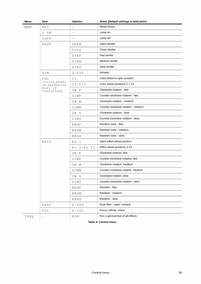
MAN RST - Reset fixture
L ON - Lamp on
LoFF - Lamp off
SHUT OPEN Open shutter
CLOS Close shutter
STRF Fast strobe
STRM Medium strobe
STRS Slow strobe
dIM 0-255 Dimmer
COL(color wheel or animation disc if installed)
C1 Color wheel in open position.
C2-C13 Color wheel positions 2 > 13.
CW F Clockwise rotation - fast
CCWF Counter-clockwise rotation - fast
CW M Clockwise rotation - medium
CCWM Counter-clockwise rotation - medium
CW S Clockwise rotation - slow
CCWS Counter-clockwise rotation - slow
RNdF Random color - fast
RNdM Random color - medium
RNdS Random color - slow
EFCT Po 1 Open effect wheel position
Po 2-Po 13 Effect wheel positions 2-13
CW F Clockwise rotation, fast
CCWF Counter-clockwise rotation, fast
CW M Clockwise rotation, medium
CCWM Counter-clockwise rotation, medium
CW S Clockwise rotation, slow
CCWS Counter-clockwise rotation - slow
RNdF Random - fast
RNdM Random - medium
RNdS Random - slow
FRST 0-255 Frost filter - open→closed
FOC 0-255 Focus, Infinity→Near
TSEQ - RUN Run a general test of all effects
Menu Item Options Notes (Default settings in bold print)
Table 4: Control menu

36 CX-10
UTIL(Press
and hold
Enter
for a
few
seconds)
Adj - Not implemented.
CAL d1OF Dimmer flag 1 offset
d2OF Dimmer flag 2 offset
CoOF Color wheel offset
GoOF Gobo wheel offset
FoOF Focus offset
FrOf Frost filter offset
dFOF Default offset. Sets all calibration offsets to 128.
dFOF SURE Return all offsets to the default settings
PCbT LEd PCB test for service use only.
UPLd SURE Manually set fixture to software update mode.
Menu Item Options Notes (Default settings in bold print)
Table 4: Control menu

Error messages 37
ERROR MESSAGES
Display readout Appears if... What to do
MERR (Memory error) ...the EEPROM memory cannot be read. • Contact service technician.
CSER (Check-sum error) ...a software upload is unsuccessful. • Reload software, see page 31.
**** ... there is no communication between the control panel and motherboard. This appears briefly when switching on the fixture.
• Check fuses.• Check cable between control panel and
motherboard.• Reinstall software.• Contact service technician.
COER (Color wheel time-out)GOER (Gobo wheel time out)
...the magnetic-indexing circuit malfunctions (e.g. sensor defective or magnet missing).
• After the time-out, the effect in question stops in a random position.
• Contact service technician.
Table 5: Error messages
38 CX-10
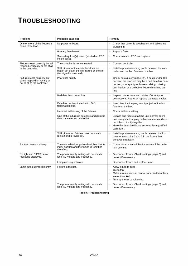
TROUBLESHOOTING
Problem Probable cause(s) Remedy
One or more of the fixtures is completely dead.
No power to fixture. • Check that power is switched on and cables are plugged in.
Primary fuse blown. • Replace fuse.
Secondary fuse(s) blown (located on PCB inside base).
• Check fuses on PCB and replace.
Fixtures reset correctly but all respond erratically or not at all to the controller.
The controller is not connected. • Connect controller.
XLR pin-out of the controller does not match pin-out of the first fixture on the link (i.e. signal is reversed).
• Install a phase-reversing cable between the con-troller and the first fixture on the link.
Fixtures reset correctly but some respond erratically or not at all to the controller.
Poor data quality • Check data quality (page 11). If much under 100 percent, the problem may be a bad data link con-nection, poor quality or broken cabling, missing termination, or a defective fixture disturbing the link.
Bad data link connection • Inspect connections and cables. Correct poor connections. Repair or replace damaged cables.
Data link not terminated with 120Ω termination plug.
• Insert termination plug in output jack of the last fixture on the link.
Incorrect addressing of the fixtures. • Check address setting.
One of the fixtures is defective and disturbs data transmission on the link.
• Bypass one fixture at a time until normal opera-tion is regained: unplug both connectors and con-nect them directly together.
• Have the defective fixture serviced by a qualified technician.
XLR pin-out on fixtures does not match (pins 2 and 3 reversed).
• Install a phase-reversing cable between the fix-tures or swap pins 2 and 3 in the fixture that behaves erratically.
Shutter closes suddenly. The color wheel, or gobo wheel, has lost its index position and the fixture is resetting the effect.
• Contact Martin technician for service if the prob-lem persists.
No light and “LERR” error message displayed.
The power supply settings do not match local AC voltage and frequency.
• Disconnect fixture. Check settings (page 6) and correct if necessary.
Lamp missing or blown • Disconnect fixture and replace lamp.
Lamp cuts out intermittently. Fixture is too hot. • Allow fixture to cool.• Clean fan. • Make sure air vents at control panel and front lens
are not blocked. • Turn up the air conditioning.
The power supply settings do not match local AC voltage and frequency.
• Disconnect fixture. Check settings (page 6) and correct if necessary.
Table 6: Troubleshooting
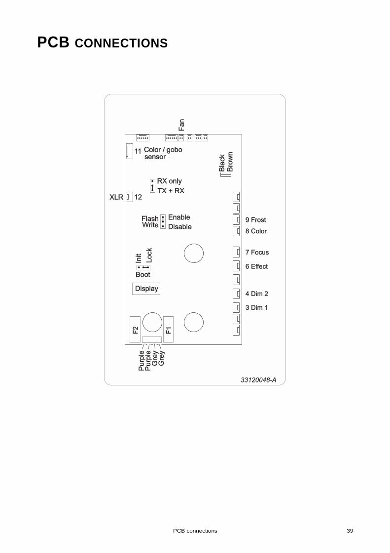
PCB connections 39
PCB CONNECTIONS
33120048-A
3 Dim 13 Dim 1
4 Dim 24 Dim 2
6 Effect6 Effect
7 Focus7 Focus
8 Color8 Color
9 Frost9 Frost
40 CX-10
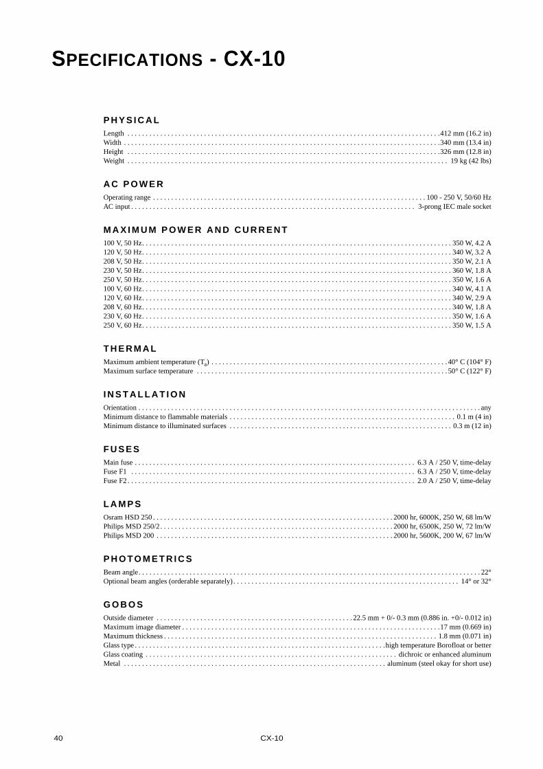
SPECIFICATIONS - CX-10
P H Y S I C A LLength . . . . . . . . . . . . . . . . . . . . . . . . . . . . . . . . . . . . . . . . . . . . . . . . . . . . . . . . . . . . . . . . . . . . . . . . . . . . . . . . . . . . . .412 mm (16.2 in)Width . . . . . . . . . . . . . . . . . . . . . . . . . . . . . . . . . . . . . . . . . . . . . . . . . . . . . . . . . . . . . . . . . . . . . . . . . . . . . . . . . . . . . . .340 mm (13.4 in)Height . . . . . . . . . . . . . . . . . . . . . . . . . . . . . . . . . . . . . . . . . . . . . . . . . . . . . . . . . . . . . . . . . . . . . . . . . . . . . . . . . . . . . .326 mm (12.8 in)Weight . . . . . . . . . . . . . . . . . . . . . . . . . . . . . . . . . . . . . . . . . . . . . . . . . . . . . . . . . . . . . . . . . . . . . . . . . . . . . . . . . . . . . . . . 19 kg (42 lbs)
A C P O W E ROperating range . . . . . . . . . . . . . . . . . . . . . . . . . . . . . . . . . . . . . . . . . . . . . . . . . . . . . . . . . . . . . . . . . . . . . . . . . . . 100 - 250 V, 50/60 HzAC input . . . . . . . . . . . . . . . . . . . . . . . . . . . . . . . . . . . . . . . . . . . . . . . . . . . . . . . . . . . . . . . . . . . . . . . . . . . . . . 3-prong IEC male socket
M A X I M U M P O W E R A N D C U R R E N T100 V, 50 Hz. . . . . . . . . . . . . . . . . . . . . . . . . . . . . . . . . . . . . . . . . . . . . . . . . . . . . . . . . . . . . . . . . . . . . . . . . . . . . . . . . . . . . 350 W, 4.2 A120 V, 50 Hz. . . . . . . . . . . . . . . . . . . . . . . . . . . . . . . . . . . . . . . . . . . . . . . . . . . . . . . . . . . . . . . . . . . . . . . . . . . . . . . . . . . . . 340 W, 3.2 A208 V, 50 Hz. . . . . . . . . . . . . . . . . . . . . . . . . . . . . . . . . . . . . . . . . . . . . . . . . . . . . . . . . . . . . . . . . . . . . . . . . . . . . . . . . . . . . 350 W, 2.1 A230 V, 50 Hz. . . . . . . . . . . . . . . . . . . . . . . . . . . . . . . . . . . . . . . . . . . . . . . . . . . . . . . . . . . . . . . . . . . . . . . . . . . . . . . . . . . . . 360 W, 1.8 A250 V, 50 Hz. . . . . . . . . . . . . . . . . . . . . . . . . . . . . . . . . . . . . . . . . . . . . . . . . . . . . . . . . . . . . . . . . . . . . . . . . . . . . . . . . . . . . 350 W, 1.6 A100 V, 60 Hz. . . . . . . . . . . . . . . . . . . . . . . . . . . . . . . . . . . . . . . . . . . . . . . . . . . . . . . . . . . . . . . . . . . . . . . . . . . . . . . . . . . . . 340 W, 4.1 A120 V, 60 Hz. . . . . . . . . . . . . . . . . . . . . . . . . . . . . . . . . . . . . . . . . . . . . . . . . . . . . . . . . . . . . . . . . . . . . . . . . . . . . . . . . . . . . 340 W, 2.9 A208 V, 60 Hz. . . . . . . . . . . . . . . . . . . . . . . . . . . . . . . . . . . . . . . . . . . . . . . . . . . . . . . . . . . . . . . . . . . . . . . . . . . . . . . . . . . . . 340 W, 1.8 A230 V, 60 Hz. . . . . . . . . . . . . . . . . . . . . . . . . . . . . . . . . . . . . . . . . . . . . . . . . . . . . . . . . . . . . . . . . . . . . . . . . . . . . . . . . . . . . 350 W, 1.6 A250 V, 60 Hz. . . . . . . . . . . . . . . . . . . . . . . . . . . . . . . . . . . . . . . . . . . . . . . . . . . . . . . . . . . . . . . . . . . . . . . . . . . . . . . . . . . . . 350 W, 1.5 A
T H E R M A LMaximum ambient temperature (Ta) . . . . . . . . . . . . . . . . . . . . . . . . . . . . . . . . . . . . . . . . . . . . . . . . . . . . . . . . . . . . . . . . . 40° C (104° F)Maximum surface temperature . . . . . . . . . . . . . . . . . . . . . . . . . . . . . . . . . . . . . . . . . . . . . . . . . . . . . . . . . . . . . . . . . . . . . 50° C (122° F)
I N S T A L L A T I O NOrientation . . . . . . . . . . . . . . . . . . . . . . . . . . . . . . . . . . . . . . . . . . . . . . . . . . . . . . . . . . . . . . . . . . . . . . . . . . . . . . . . . . . . . . . . . . . . . . anyMinimum distance to flammable materials . . . . . . . . . . . . . . . . . . . . . . . . . . . . . . . . . . . . . . . . . . . . . . . . . . . . . . . . . . . . . . 0.1 m (4 in)Minimum distance to illuminated surfaces . . . . . . . . . . . . . . . . . . . . . . . . . . . . . . . . . . . . . . . . . . . . . . . . . . . . . . . . . . . . . 0.3 m (12 in)
F U S E SMain fuse . . . . . . . . . . . . . . . . . . . . . . . . . . . . . . . . . . . . . . . . . . . . . . . . . . . . . . . . . . . . . . . . . . . . . . . . . . . . . 6.3 A / 250 V, time-delayFuse F1 . . . . . . . . . . . . . . . . . . . . . . . . . . . . . . . . . . . . . . . . . . . . . . . . . . . . . . . . . . . . . . . . . . . . . . . . . . . . . . 6.3 A / 250 V, time-delayFuse F2 . . . . . . . . . . . . . . . . . . . . . . . . . . . . . . . . . . . . . . . . . . . . . . . . . . . . . . . . . . . . . . . . . . . . . . . . . . . . . . . 2.0 A / 250 V, time-delay
L A M P S Osram HSD 250 . . . . . . . . . . . . . . . . . . . . . . . . . . . . . . . . . . . . . . . . . . . . . . . . . . . . . . . . . . . . . . . . . . 2000 hr, 6000K, 250 W, 68 lm/WPhilips MSD 250/2. . . . . . . . . . . . . . . . . . . . . . . . . . . . . . . . . . . . . . . . . . . . . . . . . . . . . . . . . . . . . . . . 2000 hr, 6500K, 250 W, 72 lm/WPhilips MSD 200 . . . . . . . . . . . . . . . . . . . . . . . . . . . . . . . . . . . . . . . . . . . . . . . . . . . . . . . . . . . . . . . . . 2000 hr, 5600K, 200 W, 67 lm/W
P H O T O M E T R I C SBeam angle. . . . . . . . . . . . . . . . . . . . . . . . . . . . . . . . . . . . . . . . . . . . . . . . . . . . . . . . . . . . . . . . . . . . . . . . . . . . . . . . . . . . . . . . . . . . . . 22°Optional beam angles (orderable separately) . . . . . . . . . . . . . . . . . . . . . . . . . . . . . . . . . . . . . . . . . . . . . . . . . . . . . . . . . . . . . . 14° or 32°
G O B O SOutside diameter . . . . . . . . . . . . . . . . . . . . . . . . . . . . . . . . . . . . . . . . . . . . . . . . . . . . . . 22.5 mm + 0/- 0.3 mm (0.886 in. +0/- 0.012 in)Maximum image diameter . . . . . . . . . . . . . . . . . . . . . . . . . . . . . . . . . . . . . . . . . . . . . . . . . . . . . . . . . . . . . . . . . . . . . . .17 mm (0.669 in)Maximum thickness . . . . . . . . . . . . . . . . . . . . . . . . . . . . . . . . . . . . . . . . . . . . . . . . . . . . . . . . . . . . . . . . . . . . . . . . . . . 1.8 mm (0.071 in)Glass type . . . . . . . . . . . . . . . . . . . . . . . . . . . . . . . . . . . . . . . . . . . . . . . . . . . . . . . . . . . . . . . . . . . . .high temperature Borofloat or betterGlass coating . . . . . . . . . . . . . . . . . . . . . . . . . . . . . . . . . . . . . . . . . . . . . . . . . . . . . . . . . . . . . . . . . . . . . dichroic or enhanced aluminumMetal . . . . . . . . . . . . . . . . . . . . . . . . . . . . . . . . . . . . . . . . . . . . . . . . . . . . . . . . . . . . . . . . . . . . . . . . aluminum (steel okay for short use)
Specifications - CX-10 41
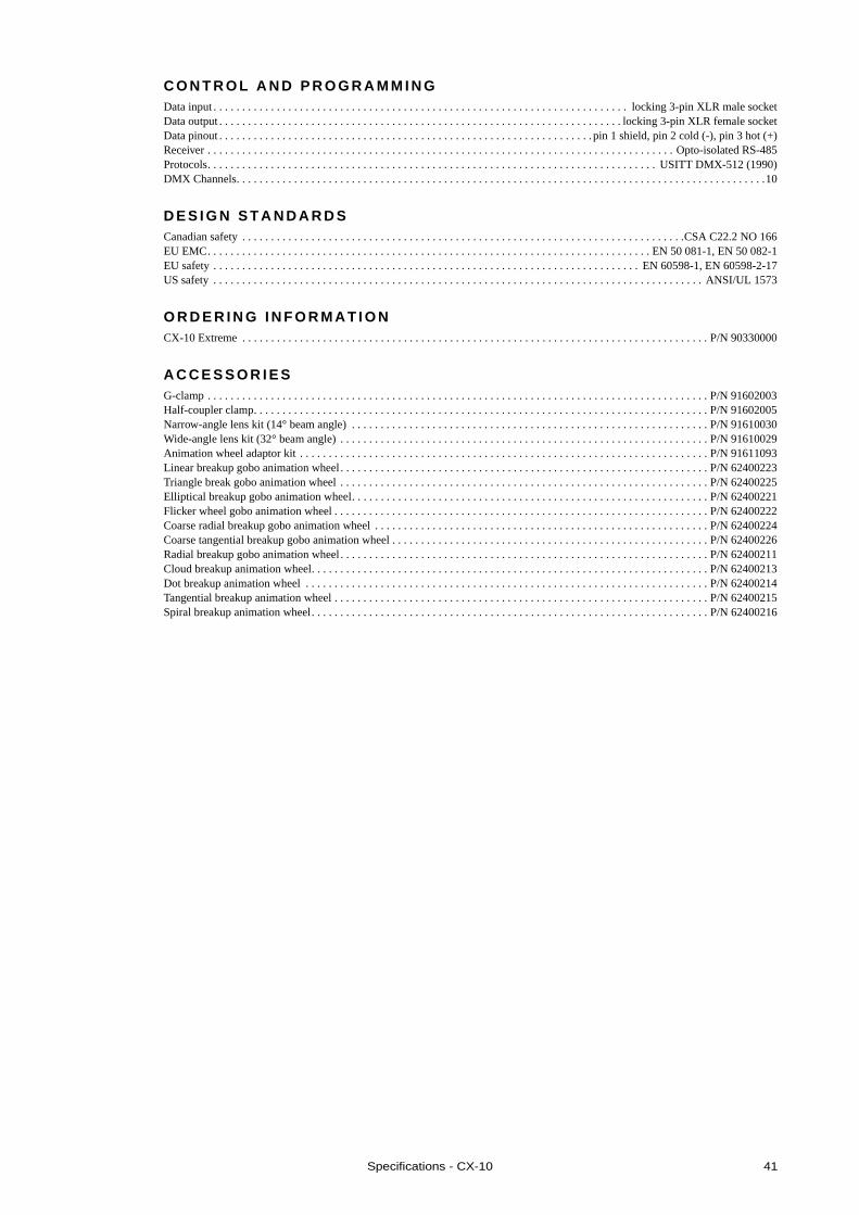
C O N T R O L A N D P R O G R A M M I N GData input . . . . . . . . . . . . . . . . . . . . . . . . . . . . . . . . . . . . . . . . . . . . . . . . . . . . . . . . . . . . . . . . . . . . . . . . locking 3-pin XLR male socketData output . . . . . . . . . . . . . . . . . . . . . . . . . . . . . . . . . . . . . . . . . . . . . . . . . . . . . . . . . . . . . . . . . . . . . . locking 3-pin XLR female socketData pinout . . . . . . . . . . . . . . . . . . . . . . . . . . . . . . . . . . . . . . . . . . . . . . . . . . . . . . . . . . . . . . . . . pin 1 shield, pin 2 cold (-), pin 3 hot (+)Receiver . . . . . . . . . . . . . . . . . . . . . . . . . . . . . . . . . . . . . . . . . . . . . . . . . . . . . . . . . . . . . . . . . . . . . . . . . . . . . . . . . Opto-isolated RS-485Protocols. . . . . . . . . . . . . . . . . . . . . . . . . . . . . . . . . . . . . . . . . . . . . . . . . . . . . . . . . . . . . . . . . . . . . . . . . . . . . . USITT DMX-512 (1990)DMX Channels. . . . . . . . . . . . . . . . . . . . . . . . . . . . . . . . . . . . . . . . . . . . . . . . . . . . . . . . . . . . . . . . . . . . . . . . . . . . . . . . . . . . . . . . . . . .10
D E S I G N S T A N D A R D SCanadian safety . . . . . . . . . . . . . . . . . . . . . . . . . . . . . . . . . . . . . . . . . . . . . . . . . . . . . . . . . . . . . . . . . . . . . . . . . . . . .CSA C22.2 NO 166EU EMC. . . . . . . . . . . . . . . . . . . . . . . . . . . . . . . . . . . . . . . . . . . . . . . . . . . . . . . . . . . . . . . . . . . . . . . . . . . . . EN 50 081-1, EN 50 082-1EU safety . . . . . . . . . . . . . . . . . . . . . . . . . . . . . . . . . . . . . . . . . . . . . . . . . . . . . . . . . . . . . . . . . . . . . . . . . . EN 60598-1, EN 60598-2-17US safety . . . . . . . . . . . . . . . . . . . . . . . . . . . . . . . . . . . . . . . . . . . . . . . . . . . . . . . . . . . . . . . . . . . . . . . . . . . . . . . . . . . . . ANSI/UL 1573
O R D E R I N G I N F O R M A T I O NCX-10 Extreme . . . . . . . . . . . . . . . . . . . . . . . . . . . . . . . . . . . . . . . . . . . . . . . . . . . . . . . . . . . . . . . . . . . . . . . . . . . . . . . . . P/N 90330000
A C C E S S O R I E SG-clamp . . . . . . . . . . . . . . . . . . . . . . . . . . . . . . . . . . . . . . . . . . . . . . . . . . . . . . . . . . . . . . . . . . . . . . . . . . . . . . . . . . . . . . . P/N 91602003Half-coupler clamp. . . . . . . . . . . . . . . . . . . . . . . . . . . . . . . . . . . . . . . . . . . . . . . . . . . . . . . . . . . . . . . . . . . . . . . . . . . . . . . P/N 91602005Narrow-angle lens kit (14° beam angle) . . . . . . . . . . . . . . . . . . . . . . . . . . . . . . . . . . . . . . . . . . . . . . . . . . . . . . . . . . . . . . P/N 91610030Wide-angle lens kit (32° beam angle) . . . . . . . . . . . . . . . . . . . . . . . . . . . . . . . . . . . . . . . . . . . . . . . . . . . . . . . . . . . . . . . . P/N 91610029Animation wheel adaptor kit . . . . . . . . . . . . . . . . . . . . . . . . . . . . . . . . . . . . . . . . . . . . . . . . . . . . . . . . . . . . . . . . . . . . . . . P/N 91611093Linear breakup gobo animation wheel . . . . . . . . . . . . . . . . . . . . . . . . . . . . . . . . . . . . . . . . . . . . . . . . . . . . . . . . . . . . . . . . P/N 62400223Triangle break gobo animation wheel . . . . . . . . . . . . . . . . . . . . . . . . . . . . . . . . . . . . . . . . . . . . . . . . . . . . . . . . . . . . . . . . P/N 62400225Elliptical breakup gobo animation wheel. . . . . . . . . . . . . . . . . . . . . . . . . . . . . . . . . . . . . . . . . . . . . . . . . . . . . . . . . . . . . . P/N 62400221Flicker wheel gobo animation wheel . . . . . . . . . . . . . . . . . . . . . . . . . . . . . . . . . . . . . . . . . . . . . . . . . . . . . . . . . . . . . . . . . P/N 62400222Coarse radial breakup gobo animation wheel . . . . . . . . . . . . . . . . . . . . . . . . . . . . . . . . . . . . . . . . . . . . . . . . . . . . . . . . . . P/N 62400224Coarse tangential breakup gobo animation wheel . . . . . . . . . . . . . . . . . . . . . . . . . . . . . . . . . . . . . . . . . . . . . . . . . . . . . . . P/N 62400226Radial breakup gobo animation wheel . . . . . . . . . . . . . . . . . . . . . . . . . . . . . . . . . . . . . . . . . . . . . . . . . . . . . . . . . . . . . . . . P/N 62400211Cloud breakup animation wheel. . . . . . . . . . . . . . . . . . . . . . . . . . . . . . . . . . . . . . . . . . . . . . . . . . . . . . . . . . . . . . . . . . . . . P/N 62400213Dot breakup animation wheel . . . . . . . . . . . . . . . . . . . . . . . . . . . . . . . . . . . . . . . . . . . . . . . . . . . . . . . . . . . . . . . . . . . . . . P/N 62400214Tangential breakup animation wheel . . . . . . . . . . . . . . . . . . . . . . . . . . . . . . . . . . . . . . . . . . . . . . . . . . . . . . . . . . . . . . . . . P/N 62400215Spiral breakup animation wheel. . . . . . . . . . . . . . . . . . . . . . . . . . . . . . . . . . . . . . . . . . . . . . . . . . . . . . . . . . . . . . . . . . . . . P/N 62400216