Embed Size (px)
Citation preview

9.0 Transmission Relay Loadability
(1). Definition: Transmission Relay Loadability means the loading permitted in the transmission line by the
relay including a security margin. The relay Loadability is to be arrived in such a way not
interfere with system operator actions, while allowing for short-term overloads, with
sufficient margin to allow for inaccuracies in the relays and instrument transformers.
Transmission relay do not prematurely trip the transmission elements out-of-service and allow
the system operators from taking controlled actions consciously to alleviate the overload.
(2). Objective:
Protective relay settings shall
1. Not limit transmission loadability;
2. Not interfere with system operators’ ability to take remedial action to protect system
reliability and;
3. Be set to reliably detect all fault conditions and protect the electrical network from these
faults.
4. This standard includes any protective functions which could trip with or without time
delay, on load current i.e. load responsive phase protection systems including but not
limited to:
i. Phase distance.
ii. Out-of-step tripping.
iii. Switch-on-to-fault.
iv. Overcurrent relays.
v. Communications aided protection schemes including but not limited to:
Permissive overreach transfer trip (POTT).
Permissive under-reach transfer trip (PUTT).
Directional comparison blocking (DCB).
Directional comparison unblocking (DCUB).
vi. Phase overcurrent supervisory elements (i.e., phase fault detectors) associated with
current based, communication-assisted schemes (i.e., pilot wire, phase comparison,
and line current differential) where the scheme is capable of tripping for loss of
communications.
5. The following protection systems are excluded from requirements of this standard:
i. Relay elements that are only enabled when other relays or associated systems fail.
For example:
Overcurrent elements that are only enabled during loss of potential conditions.
Elements that are only enabled during a loss of communications except as noted
in section 4 (vi)
ii. Protection systems intended for the detection of ground fault conditions.
iii. Protection systems intended for protection during stable power swings.
iv. Relay elements used only for Special Protection Systems.
v. Protection systems that are designed only to respond in time periods which allow 15
minutes or greater to respond to overload conditions.
vi. Thermal emulation relays which are used in conjunction with dynamic Facility
Ratings.
vii. Relay elements associated with dc lines.
viii. Relay elements associated with dc converter transformers.
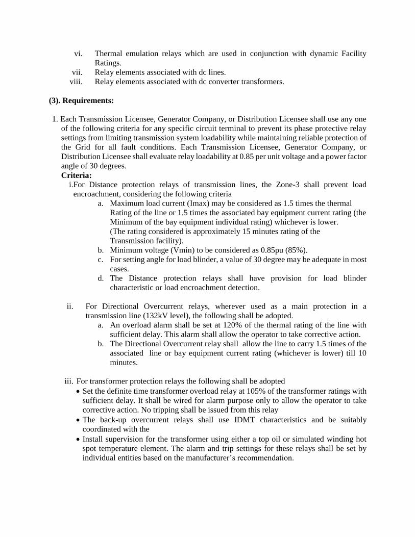
(3). Requirements:
1. Each Transmission Licensee, Generator Company, or Distribution Licensee shall use any one
of the following criteria for any specific circuit terminal to prevent its phase protective relay
settings from limiting transmission system loadability while maintaining reliable protection of
the Grid for all fault conditions. Each Transmission Licensee, Generator Company, or
Distribution Licensee shall evaluate relay loadability at 0.85 per unit voltage and a power factor
angle of 30 degrees.
Criteria:
i.For Distance protection relays of transmission lines, the Zone-3 shall prevent load
encroachment, considering the following criteria
a. Maximum load current (Imax) may be considered as 1.5 times the thermal
Rating of the line or 1.5 times the associated bay equipment current rating (the
Minimum of the bay equipment individual rating) whichever is lower.
(The rating considered is approximately 15 minutes rating of the
Transmission facility).
b. Minimum voltage (Vmin) to be considered as 0.85pu (85%).
c. For setting angle for load blinder, a value of 30 degree may be adequate in most
cases.
d. The Distance protection relays shall have provision for load blinder
characteristic or load encroachment detection.
ii. For Directional Overcurrent relays, wherever used as a main protection in a
transmission line (132kV level), the following shall be adopted.
a. An overload alarm shall be set at 120% of the thermal rating of the line with
sufficient delay. This alarm shall allow the operator to take corrective action.
b. The Directional Overcurrent relay shall allow the line to carry 1.5 times of the
associated line or bay equipment current rating (whichever is lower) till 10
minutes.
iii. For transformer protection relays the following shall be adopted
Set the definite time transformer overload relay at 105% of the transformer ratings with
sufficient delay. It shall be wired for alarm purpose only to allow the operator to take
corrective action. No tripping shall be issued from this relay
The back-up overcurrent relays shall use IDMT characteristics and be suitably
coordinated with the
Install supervision for the transformer using either a top oil or simulated winding hot
spot temperature element. The alarm and trip settings for these relays shall be set by
individual entities based on the manufacturer’s recommendation.
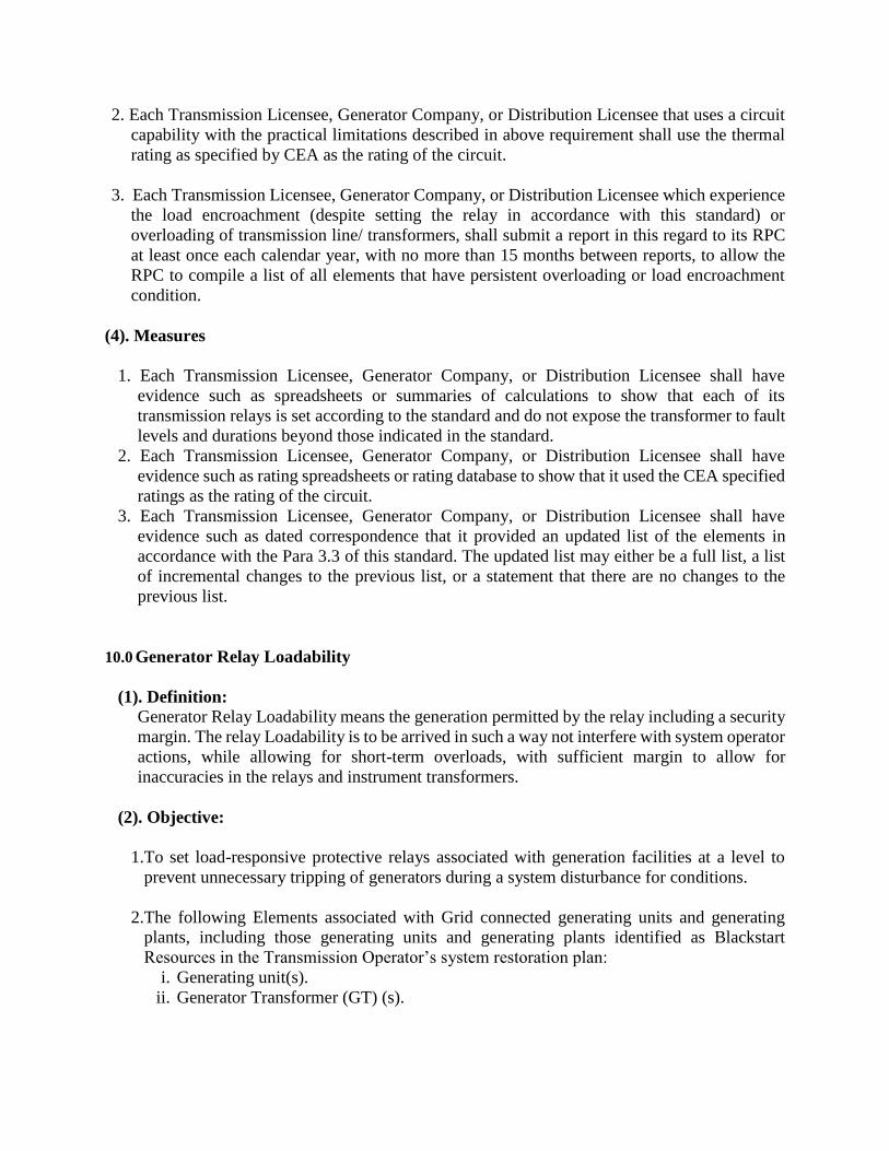
2. Each Transmission Licensee, Generator Company, or Distribution Licensee that uses a circuit
capability with the practical limitations described in above requirement shall use the thermal
rating as specified by CEA as the rating of the circuit.
3. Each Transmission Licensee, Generator Company, or Distribution Licensee which experience
the load encroachment (despite setting the relay in accordance with this standard) or
overloading of transmission line/ transformers, shall submit a report in this regard to its RPC
at least once each calendar year, with no more than 15 months between reports, to allow the
RPC to compile a list of all elements that have persistent overloading or load encroachment
condition.
(4). Measures
1. Each Transmission Licensee, Generator Company, or Distribution Licensee shall have
evidence such as spreadsheets or summaries of calculations to show that each of its
transmission relays is set according to the standard and do not expose the transformer to fault
levels and durations beyond those indicated in the standard.
2. Each Transmission Licensee, Generator Company, or Distribution Licensee shall have
evidence such as rating spreadsheets or rating database to show that it used the CEA specified
ratings as the rating of the circuit.
3. Each Transmission Licensee, Generator Company, or Distribution Licensee shall have
evidence such as dated correspondence that it provided an updated list of the elements in
accordance with the Para 3.3 of this standard. The updated list may either be a full list, a list
of incremental changes to the previous list, or a statement that there are no changes to the
previous list.
10.0 Generator Relay Loadability
(1). Definition:
Generator Relay Loadability means the generation permitted by the relay including a security
margin. The relay Loadability is to be arrived in such a way not interfere with system operator
actions, while allowing for short-term overloads, with sufficient margin to allow for
inaccuracies in the relays and instrument transformers.
(2). Objective:
1.To set load-responsive protective relays associated with generation facilities at a level to
prevent unnecessary tripping of generators during a system disturbance for conditions.
2.The following Elements associated with Grid connected generating units and generating
plants, including those generating units and generating plants identified as Blackstart
Resources in the Transmission Operator’s system restoration plan:
i. Generating unit(s).
ii. Generator Transformer (GT) (s).

iii. Unit auxiliary transformer(s) (UAT) that supply overall auxiliary power necessary to
keep generating unit(s) online.1
iv. Elements that connect the GT(s) to the Transmission system that are used exclusively
to export energy directly from a Grid connected generating unit or generating plant.
Elements may also supply generating plant loads.
v. Elements utilized in the aggregation of dispersed power producing resources.
(3). Requirements:
1. Each Generator Company, Transmission Licensee, and Distribution Licensee shall apply
settings as per the following philosophy. The detailed generator relay loadability evaluation
criterion is given at Table 1. Relay Settings, on each load-responsive protective relay while
maintaining reliable fault protection.
Generators
Synchronous generator relay pickup setting criteria values are derived from the unit’s
maximum gross Real Power capability, in megawatts (MW), as reported to the
Transmission Planner, and the unit’s Reactive Power capability, in megavoltampere-
reactive (MVAR), is determined by calculating the MW value based on the unit’s
nameplate megavoltampere (MVA) rating at rated power factor. If different seasonal
capabilities are reported, the maximum capability shall be used for the purposes of this
standard.
Asynchronous generator relay pickup setting criteria values (including inverter-based
installations) are derived from the site’s aggregate maximum complex power capability, in
MVA, as reported to the Transmission Planner, including the MVAR output of any static
or dynamic reactive power devices.
For the application case where synchronous and asynchronous generator types are
combined on a Generator Transformer (GT) or on Elements that connect the GT(s) to the
Transmission system that are used exclusively to export energy directly from a Grid
connected generating unit or generating plant (Elements may also supply generating plant
loads.), the pickup setting criteria shall be determined by vector summing the pickup setting
criteria of each generator type, and using the bus voltage for the given synchronous
generator application and relay type.
Transformers
Calculations using the GT turns ratio shall use the actual tap that is applied (i.e., in service)
for GTs with deenergized tap changers (DETC). If load tap changers (LTC) are used, the
calculations shall reflect the tap that results in the lowest generator bus voltage. When the
criterion specifies the use of the GT’s impedance, the nameplate impedance at the nominal
GT turns ratio shall be used.
Applications that use more complex topology, such as generators connected to a multiple
winding transformer may require simulation to avoid overly conservative assumptions to
simplify the calculations as these topologies can result in complex power flows. Entities
with these topologies should set their relays in such a way that they do not operate for the
conditions being addressed in this standard.
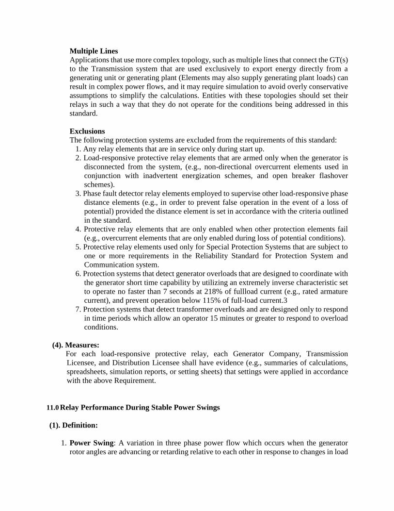
Multiple Lines Applications that use more complex topology, such as multiple lines that connect the GT(s)
to the Transmission system that are used exclusively to export energy directly from a
generating unit or generating plant (Elements may also supply generating plant loads) can
result in complex power flows, and it may require simulation to avoid overly conservative
assumptions to simplify the calculations. Entities with these topologies should set their
relays in such a way that they do not operate for the conditions being addressed in this
standard.
Exclusions
The following protection systems are excluded from the requirements of this standard:
1. Any relay elements that are in service only during start up.
2. Load-responsive protective relay elements that are armed only when the generator is
disconnected from the system, (e.g., non-directional overcurrent elements used in
conjunction with inadvertent energization schemes, and open breaker flashover
schemes).
3. Phase fault detector relay elements employed to supervise other load-responsive phase
distance elements (e.g., in order to prevent false operation in the event of a loss of
potential) provided the distance element is set in accordance with the criteria outlined
in the standard.
4. Protective relay elements that are only enabled when other protection elements fail
(e.g., overcurrent elements that are only enabled during loss of potential conditions).
5. Protective relay elements used only for Special Protection Systems that are subject to
one or more requirements in the Reliability Standard for Protection System and
Communication system.
6. Protection systems that detect generator overloads that are designed to coordinate with
the generator short time capability by utilizing an extremely inverse characteristic set
to operate no faster than 7 seconds at 218% of fullload current (e.g., rated armature
current), and prevent operation below 115% of full-load current.3
7. Protection systems that detect transformer overloads and are designed only to respond
in time periods which allow an operator 15 minutes or greater to respond to overload
conditions.
(4). Measures:
For each load-responsive protective relay, each Generator Company, Transmission
Licensee, and Distribution Licensee shall have evidence (e.g., summaries of calculations,
spreadsheets, simulation reports, or setting sheets) that settings were applied in accordance
with the above Requirement.
11.0 Relay Performance During Stable Power Swings
(1). Definition:
1. Power Swing: A variation in three phase power flow which occurs when the generator
rotor angles are advancing or retarding relative to each other in response to changes in load

magnitude and direction, line switching, loss of generation, faults, and other system
disturbances.
2. Stable Power Swing: A power swing is considered stable if the generators do not slip poles
and the system reaches a new state of equilibrium, i.e. an acceptable operating condition.
3. Unstable Power Swing: A power swing that will result in a generator or group of
generators experiencing pole slipping for which some corrective action must be taken.
(2). Objective:
1. To ensure that load-responsive protective relays are expected to not trip in response to stable
power swings during non-Fault conditions.
2. This standard applies to any protective functions which could trip instantaneously or with a
time delay of less than 15 cycles on load current (i.e., “load-responsive”) including, but not
limited to:
Phase distance
Phase overcurrent
Out-of-step tripping
Loss-of-field
The following protection functions are excluded from Requirements of this standard:
Relay elements supervised by power swing blocking
Relay elements that are only enabled when other relays or associated systems fail. For
example:
Overcurrent elements that are only enabled during loss of potential conditions.
Relay elements that are only enabled during a loss of communications
Thermal emulation relays which are used in conjunction with dynamic Facility Ratings
Relay elements associated with direct current (dc) lines
Relay elements associated with dc converter transformers
Phase fault detector relay elements employed to supervise other load-responsive phase
distance elements (i.e., in order to prevent false operation in the event of a loss of
potential)
Relay elements associated with switch-onto-fault schemes
Reverse power relay on the generator
Generator relay elements that are armed only when the generator is disconnected from
the system, (e.g., non-directional overcurrent elements used in conjunction with
inadvertent energization schemes, and open breaker flashover schemes)
Current differential relay, pilot wire relay, and phase comparison relay
Voltage-restrained or voltage-controlled overcurrent relays
(3). Requirements:
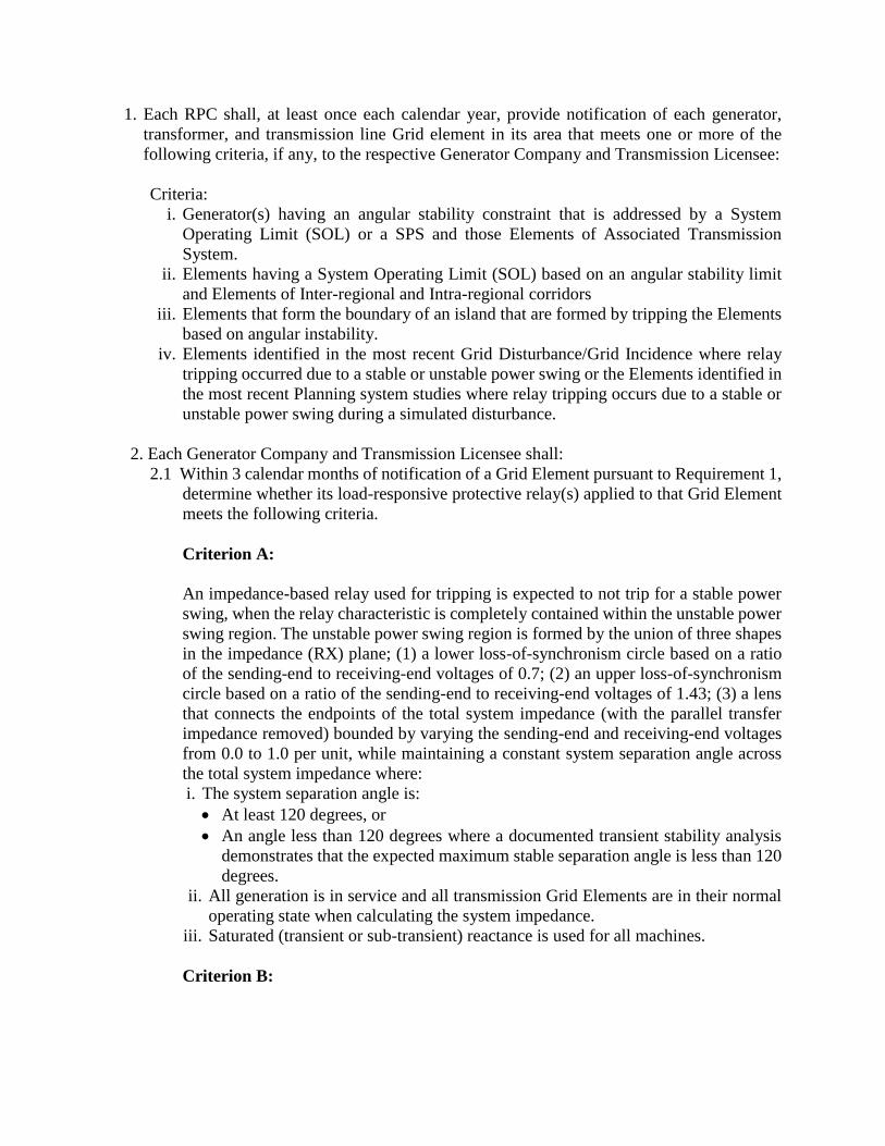
1. Each RPC shall, at least once each calendar year, provide notification of each generator,
transformer, and transmission line Grid element in its area that meets one or more of the
following criteria, if any, to the respective Generator Company and Transmission Licensee:
Criteria:
i. Generator(s) having an angular stability constraint that is addressed by a System
Operating Limit (SOL) or a SPS and those Elements of Associated Transmission
System.
ii. Elements having a System Operating Limit (SOL) based on an angular stability limit
and Elements of Inter-regional and Intra-regional corridors
iii. Elements that form the boundary of an island that are formed by tripping the Elements
based on angular instability.
iv. Elements identified in the most recent Grid Disturbance/Grid Incidence where relay
tripping occurred due to a stable or unstable power swing or the Elements identified in
the most recent Planning system studies where relay tripping occurs due to a stable or
unstable power swing during a simulated disturbance.
2. Each Generator Company and Transmission Licensee shall:
2.1 Within 3 calendar months of notification of a Grid Element pursuant to Requirement 1,
determine whether its load-responsive protective relay(s) applied to that Grid Element
meets the following criteria.
Criterion A:
An impedance-based relay used for tripping is expected to not trip for a stable power
swing, when the relay characteristic is completely contained within the unstable power
swing region. The unstable power swing region is formed by the union of three shapes
in the impedance (RX) plane; (1) a lower loss-of-synchronism circle based on a ratio
of the sending-end to receiving-end voltages of 0.7; (2) an upper loss-of-synchronism
circle based on a ratio of the sending-end to receiving-end voltages of 1.43; (3) a lens
that connects the endpoints of the total system impedance (with the parallel transfer
impedance removed) bounded by varying the sending-end and receiving-end voltages
from 0.0 to 1.0 per unit, while maintaining a constant system separation angle across
the total system impedance where:
i. The system separation angle is:
At least 120 degrees, or
An angle less than 120 degrees where a documented transient stability analysis
demonstrates that the expected maximum stable separation angle is less than 120
degrees.
ii. All generation is in service and all transmission Grid Elements are in their normal
operating state when calculating the system impedance.
iii. Saturated (transient or sub-transient) reactance is used for all machines.
Criterion B:

The pickup of an overcurrent relay element used for tripping, that is above the
calculated current value (with the parallel transfer impedance removed) for the
conditions below:
i.The system separation angle is:
At least 120 degrees, or
An angle less than 120 degrees where a documented transient stability analysis
demonstrates that the expected maximum stable separation angle is less than
120 degrees.
ii. All generation is in service and all transmission Grid Elements are in their normal
operating state when calculating the system impedance.
iii. Saturated (transient or sub-transient) reactance is used for all machines.
iv. Both the sending-end and receiving-end voltages at 1.05 per unit.
2.2 Within 3 calendar months of becoming aware of a generator, transformer, or
transmission line Grid Element that tripped in response to a stable or unstable power
swing due to the operation of its protective relay(s), determine whether its load-
responsive protective relay(s) applied to that Grid Element meets the criteria A & B.
3. Each Generator Company and Transmission Licensee shall, within 3 calendar months of
determining a load-responsive protective relay does not meet the criteria A & B pursuant to
Requirement 2, develop a Corrective Action Plan (CAP) to meet one of the following:
The Protection System meets the criteria A & B, while maintaining dependable fault
detection and dependable out-of-step tripping (if out-of- step tripping is applied at the
terminal of the Grid Element); or
The Protection System is excluded as mentioned in objective of this standard (e.g.,
modifying the Protection System so that relay functions are supervised by power swing
blocking or using relay systems that are immune to power swings), while maintaining
dependable fault detection and dependable out-of-step tripping (if out-of-step tripping is
applied at the terminal of the Grid Element).
4. Each Generator Company and Transmission Licensee shall implement each CAP developed
pursuant to Requirement 3 and update each CAP if actions or timetables change until all
actions are complete.
(4). Measures:
1. Each RPC shall have dated evidence that demonstrates notification of the generator,
transformer, and transmission line Grid Element(s) that meet one or more of the criteria in
Requirement 1, if any, to the respective Generator Company and Transmission Licensee.
Evidence may include, but is not limited to, the following documentation: emails,
facsimiles, records, reports, transmittals, lists, or spreadsheets.
2. Each Generator Company and Transmission Licensee shall have dated evidence that
demonstrates the evaluation was performed according to Requirement 2. Evidence may
include, but is not limited to, the following documentation: apparent impedance
characteristic plots, email, design drawings, facsimiles, R-X plots, software output, records,
reports, transmittals, lists, settings sheets, or spreadsheets.

3. The Generator Company and Transmission Licensee shall have dated evidence that
demonstrates the development of a CAP in accordance with Requirement 3.
4. The Generator Company and Transmission Licensee shall have dated evidence that
demonstrates implementation of each CAP according to Requirement 4, including updates
to the CAP when actions or timetables change.
Evidence in Measures 3 & 4 may include, but is not limited to, the following
documentation: corrective action plans, maintenance records, settings sheets, project or
work management program records, or work orders.
12.0 Time Synchronization Issues:
(1) Definition: Time/clock synchronization aims to coordinate independent clocks with the reference to an
accurate external time source, such as a GPS time signal. Intelligent electrical devices (IEDs) have
their own clocks, but electronic clocks are subject to drift. Even when updated frequently over a
network by application software, their clocks may vary from each other by as much as a second.
Because several events can occur during this time frame, modern power systems require more
precise coordination to ensure high reliability.
(2) Objective:
1. To have precise time synchronization for a variety of Intelligent Electronic Devices (IEDs).
2. To have accurate time synchronization to ensure high reliability of power system.
3. Time synchronization for substations with integrated protection- and system control
functions, as well as data collection require a target architecture that distributes synchronized
time in several ways.
(3) Requirements:
1. Each substation shall have time synch equipment including external time source to
synchronize all the numerical relays installed. Before any extension work, the capability of
the existing Time-sync equipment shall be reviewed to ensure the synchronization of
upcoming numerical relays.
2. The status of healthiness of the time-sync equipment shall be wired as “Alarm” to SCADA
and as an “Event” to Event Logger.
3. The time synch status of all the installed numerical relays and event logger shall be
monitored monthly and recorded.
4. The Monthly records for relays not in time-sync shall be reported to concerned SLDC/RLDC
and RPC. This record shall be archived for a period of three years by each concerned agency.
5. Remedial action shall be taken by the concerned substation/ Protection department
immediately to make the relays in time synchronization with reference to external time
source.
(4) Measures:
1. Each substation shall have evidence that it reviewed the capability of the existing Time-sync
equipment before any extension work for synchronization upcoming numerical relays.
2. Each substation shall review the status of healthiness of the Time-sync equipment being
recorded.
3. Each substation shall have evidence that the time synch status of all the installed numerical
relays and event logger are monitored monthly and recorded.
4. Each substation shall have evidence that the monthly records for relays not in time-sync are
reported to concerned SLDC/RLDC and RPC.
5. Each substation or concerned protection department shall have evidence that remedial action
was taken to make the relays in time synchronization with reference to external time source.
13.0 DC system
(1)Definition:
DC system in a substation consists of battery charger and battery sets. DC batteries are used to
provide back-up to control power supply to all the protection, control and automation equipment
for fail safe operation of the plant.
(2) Objective:
To test the condition of DC system for a reliable, dependable and secured DC Power Supply Block
and form essential part of the protection and control system in the substation or the power plant.
(3) Requirements:
1. D.C. Power Supply shall comprise of Battery and a Battery Charger in parallel operation. In
this mode, the charger shall be required to not only continuously feed a variable load but also
deliver trickle/boost charging current for the battery. Battery will be capable of feeding the DC
load requirement of the Sub-station in case of failure of the charger.
2. There shall be minimum of two battery sets in a substation.
3. Each battery shall have sufficient capacity considering continuous emergency and
intermittent loads for the periods specified below and for all bays (i.e. present and future bays)
with the charger out of service :
a) Continuous DC load for protection, control, indications, alarms and interlock for 10 hours.
b) Emergency lighting loads for 10 hours.
c) Intermittent DC load for closing and tripping operation of Circuit Breakers, Isolators and
Earth Switches. This load shall be determined considering simultaneous tripping of
breakers on bus-bar protection for 220KV and above substations. Duration of
intermittent load shall be considered as one minute. Battery shall have 20% spare
capacity.
4. Each utility shall carryout the testing of DC system in its substation(s) once in a month as per
the following procedure.
(A). Battery Charger
Visual Inspection: The battery charger cleanliness to be verified. Proper cable
termination of incoming AC cable and the outgoing DC cable and the cable connection
between battery and charger to be ensured. A stable incoming AC supply to the battery
charger is also to be ensured.
Voltage levels in the Float charge mode and the Boost charge mode to be set according
to specifications using potentiometer provided.
Battery low voltage, Mains ‘Off”, charger ‘Off’ etc., conditions are simulated and
checked for proper alarm / indication. Thus functional correctness of the battery charger
is ensued.
Battery charger put in fast charging boost mode and battery set boost charged for the
duration specified by the battery manufacturer.
After the boost charging duration, the battery charger is to be put in float charging (trickle
charge) mode for continuous operation.
Some chargers automatically switch to float charge mode after the charging current
reduces below a certain value.
Voltage and current values are recorded during the boost charging and float-charging
mode.
(B). Battery Unit
Visual Inspection: Cleanliness of battery is checked and the electrolyte level checked as
specified on the individual cells. The tightness of cell connections on individual terminals
should be ensured.
The load current, minimum voltage of battery system, ampere-hour, duration etc., is
preset in the test equipment using the keypad.
For (e.g.) a 58 AH battery set, 5 Hr. duration specification 11.6 A and 5 Hr. duration are
set. Minimum voltage setting is = No. of cells x end cell voltage of cells as per
manufacturer specification.
It is to be ensured that the set value of the current and duration is within the discharge
capacity of the type of cell used. Also the total power to be dissipated in the load unit
should be within the power rating of the battery load kit.
Individual cell voltages to be recorded before the start of the test.
Battery charger to be switched off/load MCB in charger to be switched off.
Loading of the battery to be started at the specified current value.
Individual cell voltages of the battery set are to be recorded every half an hour.
It is to be ensured that all the cell voltages are above the end-cell voltage specified by the
manufacturer.
If any of the cell voltages falls below the threshold level specified by the manufacturer,
this cell number is to be noted and the cell needs to be replaced.
Test set automatically stops loading after set duration (or) when minimum voltage
reached for the battery set.
Test to be continued until the battery delivers the total AH capacity it is designed for.
Value of AH and individual cell voltages to be recorded every half an hour.
(4). Measures:
1. Each utility shall have evidence that it reviewed the capacity of charger in a substation to
continuously feed a variable load and deliver trickle/boost charging current for the battery.
Each utility shall have evidence that it reviewed the capacity of Battery set is capable of
feeding the DC load requirement of the Sub-station in case of failure of the charger.
2. Each utility shall have evidence that substation battery sets have sufficient capacity
considering continuous emergency and intermittent loads for the periods specified under
Requirement 3.
3. Each utility shall keep the monthly test reports of charger and battery sets in substation at
least for the duration of 3 years.
14.0 Minimum event list for Event logging facility
This topic is already covered in the broad area 2.0 DISTURBANCE MONITORING AND
REPORTING Item no. 2. Member may please discuss.
15.0 Compliance Monitoring of Reliability Standard for Protection system
1. RPC shall be responsible for the compliance monitoring for Reliability Standard for
Protection system
2. The following methods shall be used to assess compliance:
(i) Self-certification (annually and submit to RPC)
(ii) Periodic Protection Audit (Conduct once in a year for critical substations as listed
by RPC and once in three years for other substations according to schedule prepared
by RPC)
(iii)Triggered Protection Audit (Conduct within 30 days for the substation where Grid
Incident/ Disturbance occurred or complaint of noncompliance.)
3. The RPC shall constitute a Protection Audit team preferably representative of RPC / NPC
Secretariat, CTU or POSOCO, entity other than entity being audited to assess compliance.
The checklist for the protection audit shall be finalized in the appropriate subcommittee
of RPC.
4. The review of the Protection Audit report shall be carried out in appropriate subcommittee
of RPC.

5. RPC Secretariat shall issue the Protection standard compliance certificate to RLDC/SLDC
for allowing the connection of the new generation or transmission assets to the Grid.
6. All the Transmission licensee, Generator Company and Distribution Licensee shall keep
evidence to validate the compliance of the Reliability standard for Protection system and
protection audit reports.
7. RPC shall keep all compliance monitoring reports/audit reports at least for five years.