Embed Size (px)
Citation preview
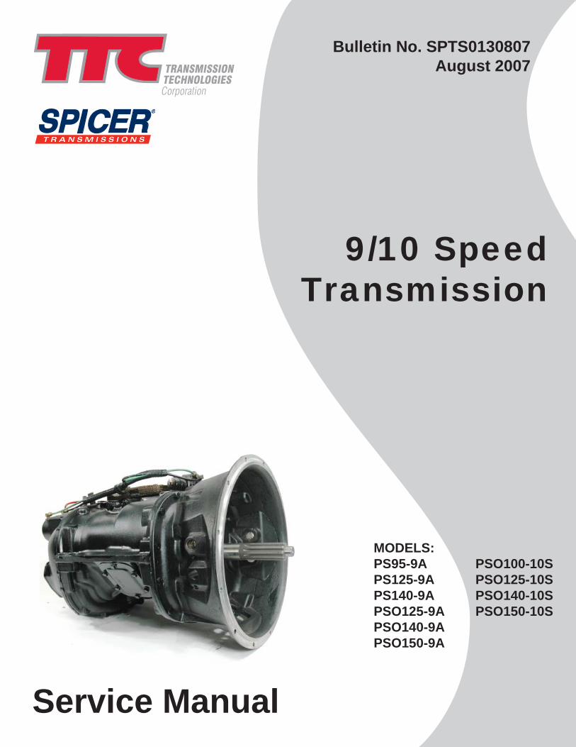
Service Manual
9/10 SpeedTransmission
Bulletin No. SPTS0130807August 2007
MODELS:PS95-9A PSO100-10SPS125-9A PSO125-10SPS140-9A PSO140-10SPSO125-9A PSO150-10SPSO140-9APSO150-9A
9 SPEED TRANSMISSION
This symbol indicates a potentially hazardous situation. If the instructions aren't followed, the result could be death or serious injury.
This symbol indicates that you must do some thing in order for the transmission to function properly. For example, you must use only one gasket underneath the shift tower. If it is eliminated, or more than one gasket is used, binding can occur. This would prevent proper shifting of the transmission and could damagethe unit.
This symbol indicates that you must NOT do something in order to avoid damaging the transmission. For example, you must not use sealantunderneath the shift tower. Using sealant underneath the tower will prevent proper interlock functioning and could damage the unit.
SAFETY FIRST
Carefully read this service manual before beginning any work on your Spicer transmission.
Throughout this literature, you will see symbols that warn of potential physical danger or product damage if the accompanying instructions aren't followed. Here are the symbols and their meanings.
Be sure you understand all procedures and instructions in this manual before you begin working on your Spicer Transmission. If you have any questions, contact your Spicer® Transmission representative.
The information in this service manual was current at the time of publication. This information is subject to change at any time without notice.
Use a hoist whenever lifting the transmission or shaft assemblies. Using a hoist can help prevent muscle strain or other possible injuries.
Always wear safety glasses when working on the transmissions to help prevent possible eye injury due to small parts (such as snap rings) or metal chips that may fly up unexpectedly during a teardown or rebuild.
Be careful when picking up gears or other sharp components. If you aren't careful, you could cut your hands. Consider wearing heavy cloth gloves or covering sharp objects with shop towels before picking them up.
When draining the transmission prior to working on it, be careful to let the unit cool down first. Otherwise, hot transmission fluid could cause burns.
General Safety Precautions
2
tech line 800-401-9866 www.ttcautomotive.com
SECTION l GENERAL INFORMATION
9-SPEED SPECIFICATIONS 4 10 -SPEED SPECIFICATIONS 4B TORQUE SPECIFICATIONS 5 DRIVER INSTRUCTIONS 6-7
SECTION II MAINTENANCE
AIR LINE PIPING DIAGRAM 8 FILTER REGULATOR 9 LUBRICATION 10
SECTION Ill GENERAL DISASSEMBLY 11-12 SECTION IV SHIFT TOWER DISASSEMBLY 13 SECTION V REMOTE CONTROL DISASSEMBLY 14 SECTION VI RANGE CASE DISASSEMBLY
CASE EXPLODED DRAWING 15 GEARS EXPLODED DRAWING 16 DISASSEMBLY 17-21
SECTION VII MAIN CASE DISASSEMBLY
CASE & SHIFT FORKS EXPLODED DRAWING 22 CLUTCH HOUSING EXPLODED DRAWING 23 MAIN CASE OPTILUBE EXPLODED DRAWING 24 MAIN CASE GEARS EXPLODED DRAWING 25 DISASSEMBLY 26-28
SECTION VIII COUNTERSHAFT DISASSEMBLY & REASSEMBLY 29 SECTION IX CLEANING & INSPECTION PROCEDURES 30 SECTION X MAIN CASE REASSEMBLY 31-33 SECTION XI RANGE CASE REASSEMBLY 34-38 SECTION XII REMOTE CONTROL REASSEMBLY 39 SECTION XIII SHIFT TOWER REASSEMBLY 40 SECTION XIV TROUBLESHOOTING 41-44
GENERAL INFORMATION
Section I
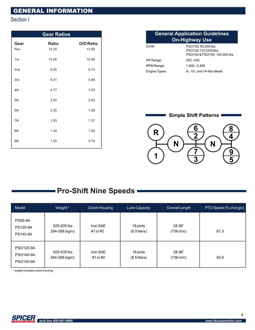
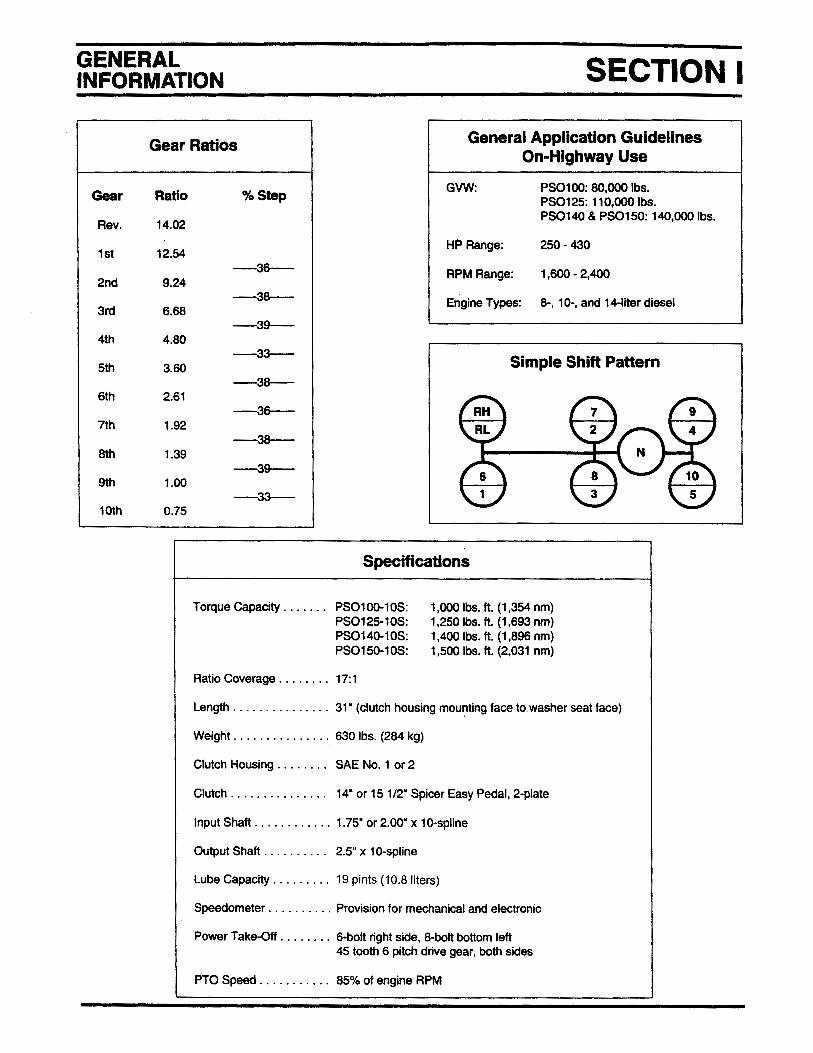
General Application GuidelinesOn-Highway Use
GVW: PSO100: 80,000 Ibs.PSO125:110,OOOIbs.PSO140 & PSO150: 140,000 Ibs.
HP Range: 250 - 430
RPM Range: 1,600 - 2,400
Engine Types: 8-, 10-, and 14-liter diesel
Gear Ratios
PS95-9A
PS125-9A
PS140-9A
PSO125-9A
PSO140-9A
PSO150-9A
Simple Shift Patterns
Gear Ratio O/D Ratio Rev 14.30 13.95
1st 13.95 10.40
2nd 9.05 6.74
3rd 6.51 4.85
4th 4.77 3.55
5th 3.55 2.65
6th 2.55 1.89
7th 1.83 1.37
8th 1.34 1.00
9th 1.00 0.74
R
1
N N
62
84
95
73
Pro-Shift Nine Speeds
Model Weight * Clutch Housing Lube Capacity Overall Length PTO Speed (% of engin)
625-635 lbs. Iron SAE 18 pints 28.96”
284-288 (kgm) #1 or #2 (8.5 liters) (736 mm) 61.5
625-635 lbs. Iron SAE 18 pints 28.96”
284-288 (kgm) #1 or #2 (8.5 liters) (736 mm) 82.6
* weight includes clutch housing
4
tech line 800-401-9866 www.ttcautomotive.com
GENERAL INFORMATION
Section I
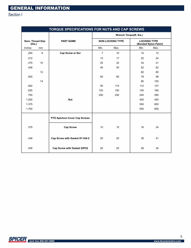
Inches mm Min. Max. Min. Max.
.250 6 Cap Screw or Nut 7 10 10 13
.312 13 17 20 24
.375 10 25 32 34 41
.438 40 50 52 62
12 60 80
.500 60 80 78 98
14 80 100
.562 90 115 112 137
.625 120 150 150 180
.750 200 250 240 290
1.250 Nut 400 450
1.375 550 600
1.750 550 600
PTO Aperture Cover Cap Screws
.375 Cap Screw 10 15 16 24
.438 Cap Screw with Gasket 97-324-2 20 25 36 41
.438 Cap Screw with Gasket 22P22 20 25 29 34
Wrench Torque(ft. Ibs.)
TORQUE SPECIFICATIONS FOR NUTS AND CAP SCREWS
Nom. Thread Size PART NAME NON-LOCKING TYPE LOCKING TYPE (Dia.) (Bonded Nylon Patch)
5
tech line 800-401-9866 www.ttcautomotive.com

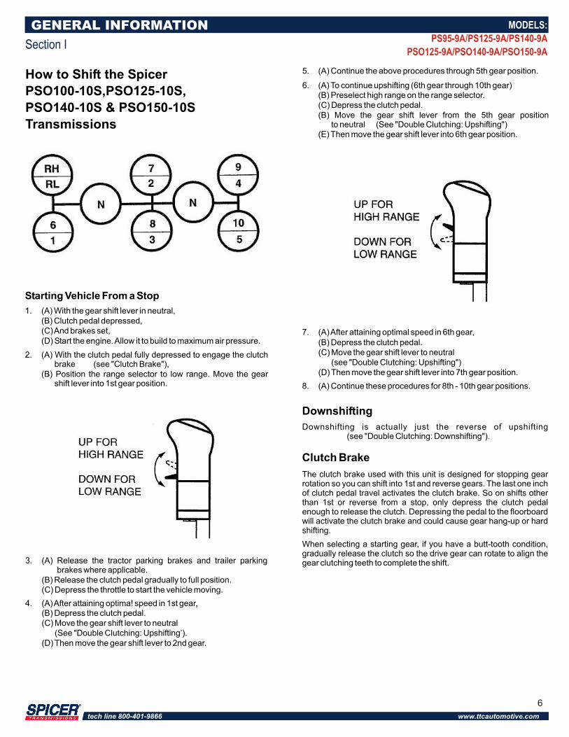
How to Shift the Spicer
PSO100-10S,PSO125-10S,
PSO140-10S & PSO150-10S
Transmissions
3. (A) Release the tractor parking brakes and trailer parking brakes where applicable.(B) Release the clutch pedal gradually to full position.(C) Depress the throttle to start the vehicle moving.
4. (A) After attaining optima! speed in 1st gear,(B) Depress the clutch pedal.(C) Move the gear shift lever to neutral (See "Double Clutching: Upshifting’).(D) Then move the gear shift lever to 2nd gear.
5. (A) Continue the above procedures through 5th gear position.
6. (A) To continue upshifting (6th gear through 10th gear)(B) Preselect high range on the range selector.(C) Depress the clutch pedal.(B) Move the gear shift lever from the 5th gear position to neutral (See "Double Clutching: Upshifting")(E) Then move the gear shift lever into 6th gear position.
GENERAL INFORMATION
Section I
7. (A) After attaining optimal speed in 6th gear,(B) Depress the clutch pedal.(C) Move the gear shift lever to neutral (see "Double Clutching: Upshifting")(D) Then move the gear shift lever into 7th gear position.
8. (A) Continue these procedures for 8th - 10th gear positions.
Downshifting
Downshifting is actually just the reverse of upshifting (see "Double Clutching: Downshifting").
Clutch Brake
The clutch brake used with this unit is designed for stopping gear rotation so you can shift into 1st and reverse gears. The last one inch of clutch pedal travel activates the clutch brake. So on shifts other than 1st or reverse from a stop, only depress the clutch pedal enough to release the clutch. Depressing the pedal to the floorboard will activate the clutch brake and could cause gear hang-up or hard shifting.
When selecting a starting gear, if you have a butt-tooth condition, gradually release the clutch so the drive gear can rotate to align the gear clutching teeth to complete the shift.
Starting Vehicle From a Stop
1. (A) With the gear shift lever in neutral,(B) Clutch pedal depressed,(C) And brakes set,(D) Start the engine. Allow it to build to maximum air pressure.
2. (A) With the clutch pedal fully depressed to engage the clutch brake (see "Clutch Brake"),(B) Position the range selector to low range. Move the gear shift lever into 1st gear position.
MODELS:
PS95-9A/PS125-9A/PS140-9A
PSO125-9A/PSO140-9A/PSO150-9A
6
tech line 800-401-9866 www.ttcautomotive.com
Double Clutching
Upshifting: The normal double clutching technique is suggested. When you want to shift, depress the clutch and move the lever to neutral. Engage the clutch and allow the engine RPM to drop so engine speed and driveline speed match. Depress the clutch and move the lever into gear. Engage the clutch and accelerate as conditions permit.
Downshifting: Downshifting is the reverse of upshifting. As the engine approaches the shift point (start the downshift approximately 50 -100 RPM above the shift point), depress the clutch and move the lever to neutral. Engage the clutch and raise the engine RPM until the engine and driveline speeds are equal (normally, governed speed). Depress the clutch, then shift into the next lower gear. Engage the clutch.
Skip ShiftingExperienced drivers sometimes want to skip some of theratios. This is acceptable. However, you should do this onlywhen operating conditions allow. Your speed, the load, andThe road type and condition should be considered.
Double clutch when shifting. This will help components match speed better during shifts and will help ensure proper engagement.
Downshift through all gear speeds when you are slowing down. Chassis and trailer brake life can be increased by doing this.
Do not force the shift since this can cause damage to clutch collars and clutching teeth. Use steady force on the shift lever to complete shifts.
Do not coast in neutral. The vehicle could lose RPM’s during coasting and you may not be able to shift back into the proper gear.
Do not downshift at road speeds that are too fast. This could prevent proper gear engagement and could damage clutching teeth.
Do not tow vehicles without first pulling the axles or disconnecting the driveshaft. If you tow the vehicle without doing this, you can damage drive train components because the system lubrication is inadequate when the vehicle is towed.
GENERAL INFORMATION
Section I
MODELS:
PS95-9A/PS125-9A/PS140-9A
PSO125-9A/PSO140-9A/PSO150-9A
Reminders
7
tech line 800-401-9866 www.ttcautomotive.com
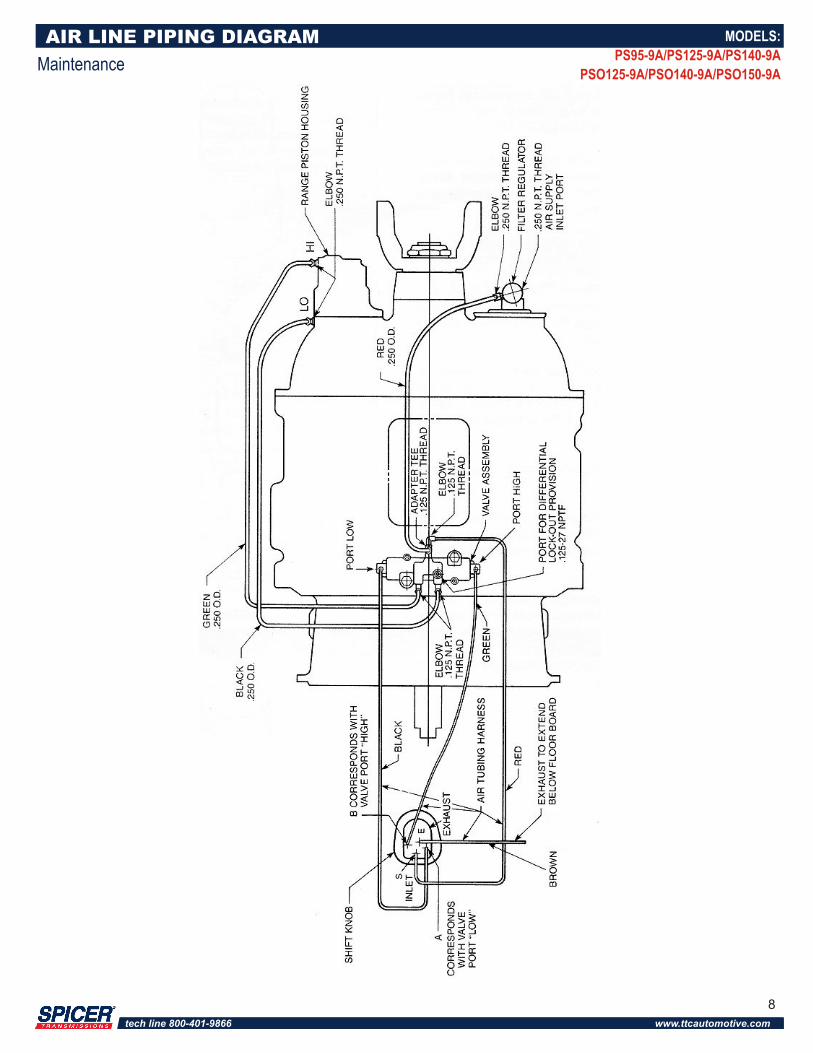
AIR LINE PIPING DIAGRAM
Maintenance
MODELS:
PS95-9A/PS125-9A/PS140-9A
PSO125-9A/PSO140-9A/PSO150-9A
8
tech line 800-401-9866 www.ttcautomotive.com
Use only petroleum-based solvents to clean parts. Other types of solvents could damage filter components and affect proper operation.
Blow air through the filter (inside and outside) to dislodge surface contaminants. Otherwise, these contaminants could affect proper filter operation and lead to equipment damage.
Do not disassemble the regulator section (9): it is not field-repairable. If it is damaged, replace it.
MAINTENANCE
Section II
MODELS:
PS95-9A/PS125-9A/PS140-9A
PSO125-9A/PSO140-9A/PSO150-9A
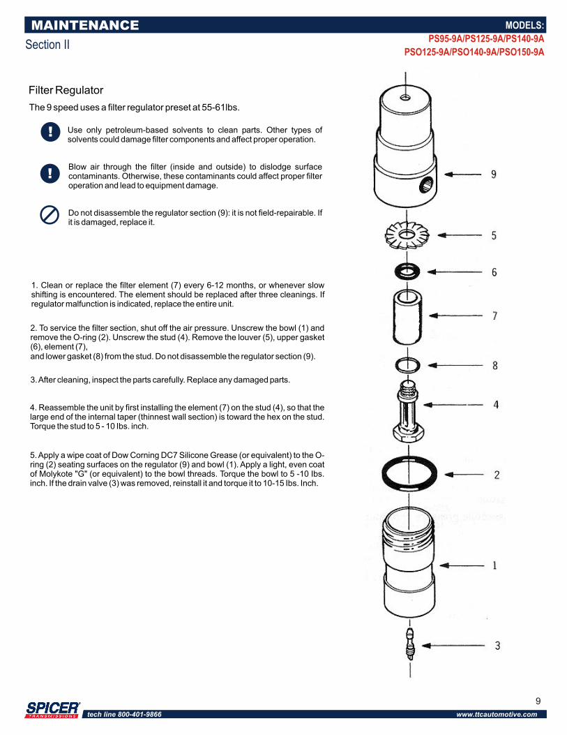
1. Clean or replace the filter element (7) every 6-12 months, or whenever slow shifting is encountered. The element should be replaced after three cleanings. If regulator malfunction is indicated, replace the entire unit.
2. To service the filter section, shut off the air pressure. Unscrew the bowl (1) and remove the O-ring (2). Unscrew the stud (4). Remove the louver (5), upper gasket (6), element (7),and lower gasket (8) from the stud. Do not disassemble the regulator section (9).
3. After cleaning, inspect the parts carefully. Replace any damaged parts.
4. Reassemble the unit by first installing the element (7) on the stud (4), so that the large end of the internal taper (thinnest wall section) is toward the hex on the stud. Torque the stud to 5 - 10 Ibs. inch.
5. Apply a wipe coat of Dow Corning DC7 Silicone Grease (or equivalent) to the O-ring (2) seating surfaces on the regulator (9) and bowl (1). Apply a light, even coat of Molykote "G" (or equivalent) to the bowl threads. Torque the bowl to 5 -10 Ibs. inch. If the drain valve (3) was removed, reinstall it and torque it to 10-15 Ibs. Inch.
Filter Regulator
The 9 speed uses a filter regulator preset at 55-61lbs.
9
tech line 800-401-9866 www.ttcautomotive.com
Lubrication
CAUTION: To ensure proper lubrication and operating temperatures in this unit, the proper lubricants must be used. Correct oil levels must be maintained. Spicer recommends using only lubricants produced by reputable, well-known suppliers. If you want to use a lubricant not specified below, please contact your local truck dealer to determine whether the lubricant is suitable for your purposes.
Recommended Lubricants
The lubricants listed below are recommended for use in all Spicer mechanical transmissions, auxiliaries, and transfer cases.
Oil Changes
Many factors influence oil change periods. Changes should be scheduled at three years or 250,000 miles with synthetic engine oil for normal over-the-highway operations. Off-highway use usually requires an oil change every 1,000 hours. The oil level in the transmission should be checked every 5,000 miles (8,045 km) on-highway, or every 40 hours in off-highway operation. When it is necessary to add oil, Spicer recommends that types and brands of oil not be mixed. The correct oil level in this transmission is established by the filler plug opening.
Refill
First, remove all dirt around the filler plug. Then refill the transmission with new oil. Use the grade recommended for the existing season and prevailing service. The lubricant should be level with the oil fill plug located on the left side of the transmission case.
Overfilling:
CAUTION: Do not overfill the transmission. This usually results in oil breakdown due to excessive heat and aeration from the churning action of the gears. Early breakdown of the oil will result in heavy varnish and sludge deposits that plug up oil ports and build up on splines and bearings
MAINTENANCE
Section II
MODELS:
PS95-9A/PS125-9A/PS140-9A
PSO125-9A/PSO140-9A/PSO150-9A
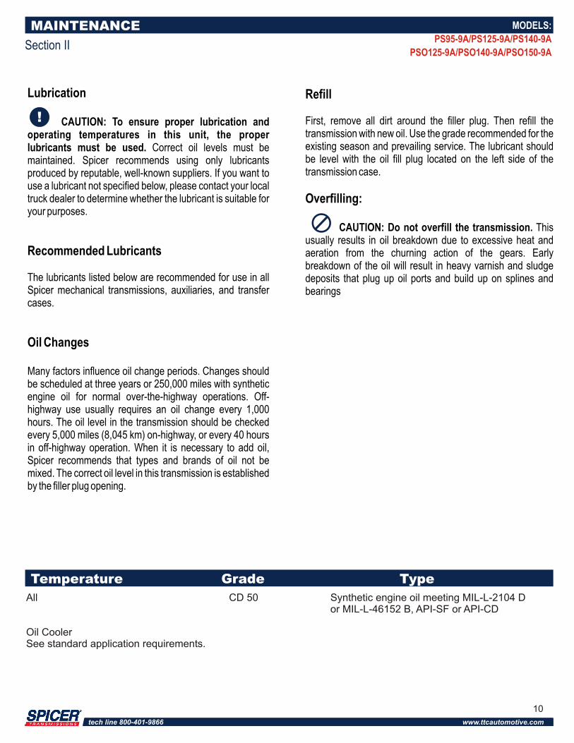
Temperature Grade Type
All CD 50 Synthetic engine oil meeting MIL-L-2104 Dor MIL-L-46152 B, API-SF or API-CD
Oil CoolerSee standard application requirements.
10
tech line 800-401-9866 www.ttcautomotive.com
Important Procedure
To locate and correct unit power or auxiliary transmission troubles, a systematic procedure should be followed.
Road test whenever possible. Mechanics usually get second- or third-hand reports of trouble experienced with the unit. These reports do not always accurately describe the actual conditions. Sometimes symptoms seem to indicate trouble in the transmission, while actually the problem is with the axle, driveshaft, universal joints, engine or clutch. This is especially true of noise complaints. Therefore, before removing the transmission or related components to locate trouble, road test to check the possibility of trouble in other closely associated units. Road testing is most effective when the mechanic drives the vehicle. However, riding with the driver can be very informative.
Check FunctioningPrior to Disassembly
If a remote control is used, a careful check of the remote and connecting linkages (and their adjustment) must be made. The remote unit must be in good working order if the transmission is expected to shift satisfactorily.
Many times, the answer to the trouble is apparent when the unit is inspected prior to disassembly. But this evidence is often lost when the parts are separated. If possible, check the unit prior to disassembly. Bear in mind that a careful inspection of the unit should be made as each disassembly step is performed.
Inspect ThoroughlyDuring Disassembly
It is poor practice to disassemble a unit or the complete transmission as quickly as possible without examining the parts. The mechanic may completely disassemble a unit and fail to find the cause of the trouble, unless he examines the parts. After the transmission is disassembled, check the lubricant for foreign particles. This is a source of trouble often overlooked during the disassembly.
Repair or Replace Worn Parts
Many times the parts or critical adjustments causing the trouble are not replaced or corrected because the mechanic only inspects and replaces parts that have failed completely. All pieces should be carefully examined because broken parts are often just the result not the cause of the problem. All parts that are broken or worn and no longer meet specifications should be replaced.
Also, parts that are worn to the extent that they do not have a long service life remaining should be replaced. Replacing these parts now will avoid another teardown on the unit in the near future. Also at this time, make the recommended changes or modifications to bring the transmission up to date and increase the service life of the unit.
GENERAL DISASSEMBLY
Section III
MODELS:
PS95-9A/PS125-9A/PS140-9A
PSO125-9A/PSO140-9A/PSO150-9A
11
tech line 800-401-9866 www.ttcautomotive.com
Rebuild Facilities
A suitable holding fixture or overhaul stand with a hole for the input shaft is desirable.
For easier working conditions, table height should be 28 - 30 inches. A light chain hoist should be used to handle the mainshaft and countershafts during removal and reassembly procedures.
Cleanliness
Transmissions should be steam cleaned prior to disassembly. Seal all openings before steam cleaning to prevent entry of dirt and water which can damage serviceable parts.
Dirt is abrasive and will cause premature wear of bearings and other parts. Spicer suggests that mechanics have a wash tank available to clean parts just prior to reassembly.
BearingsWhen a transmission is removed at relatively low mileage, bearings should be removed with pullers designed for this purpose. Wrap the bearings to keep out dirt. Clean, inspect, and lubricate all bearings just prior to reassembly. If accumulated mileage is over 150,000 miles, we suggest that all bearings be replaced. If bearings are worn or damaged, always replace them regardless of mileage.
Read this section before starting the detailed disassembly procedures. Follow procedures closely to ensure proper transmission operation.
Do not hammer on end yokes and flanges to remove or install them. It is not only destructive to the yoke or the flange itself, but can also cause seriousinternal transmission damage. Hammering destroys or mutilates the pilot diameters and warps or bends the flange. Hammering on end yokes will close-in the bearing bores or misalign yoke lugs. This will result in early failures of journal needle bearings.
Serious damage can be done internally to bearings, thrust faces and washers by hammering on external parts. In most designs, when the yoke/flange locknuts are tightened and secure, the internal bearings and gears are in proper location. When the yoke/flange is driven on the shaft, however, two conditions can exist.
(A) If the bearing fit is tight on the shaft, usually the bearings will brinell as they must absorb the pounding force.
(B) If the bearing fit is loose, the shaft will keep moving inward until it is stopped by the internal parts such as the pilot bearing thrust washers.
These conditions must be prevented.
Power Take-Offs
Refer to your owner's manual, installation procedures, and safety precaution when installing any PTO on your transmission.
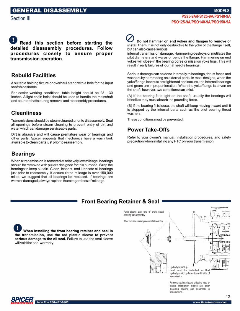
When installing the front bearing retainer and seal in the transmission, use the red plastic sleeve to prevent serious damage to the oil seal. Failure to use the seal sleeve will void the seal warranty.
GENERAL DISASSEMBLY
Section III
Front Bearing Retainer & Seal
Hydrodynamic LipSeal must be installed so that Hydrodynamic Lip faces toward inside of transmission.
Remove seal cardboard shipping tube or plastic installation sleeve just prior installing bearing cap assembly to transmission.
Push sleeve over end of shaft install bearing cap assembly
After red sleeve is in place install seal dry
MODELS:
PS95-9A/PS125-9A/PS140-9A
PSO125-9A/PSO140-9A/PSO150-9A
12
tech line 800-401-9866 www.ttcautomotive.com
SHIFT TOWER DISASSEMBLY
Section IV
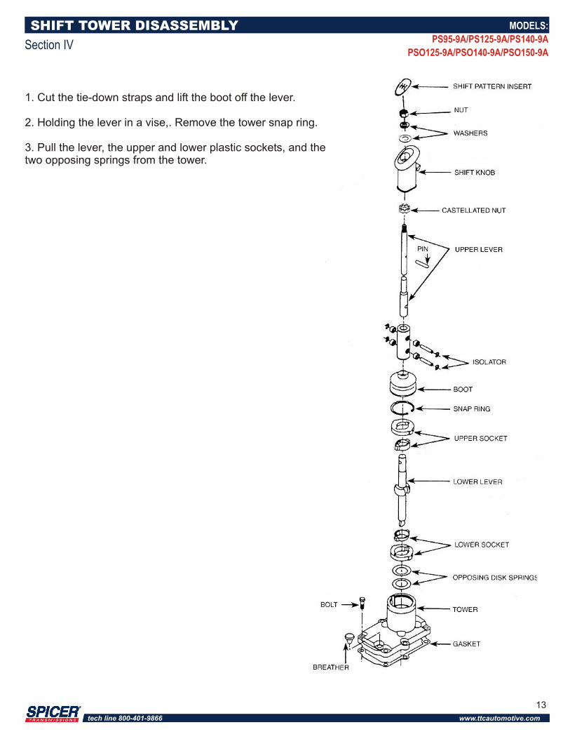
1. Cut the tie-down straps and lift the boot off the lever.
2. Holding the lever in a vise,. Remove the tower snap ring.
3. Pull the lever, the upper and lower plastic sockets, and the two opposing springs from the tower.
MODELS:
PS95-9A/PS125-9A/PS140-9A
PSO125-9A/PSO140-9A/PSO150-9A
13
tech line 800-401-9866 www.ttcautomotive.com
REMOTE CONTROL DISASSEMBLY
Section V
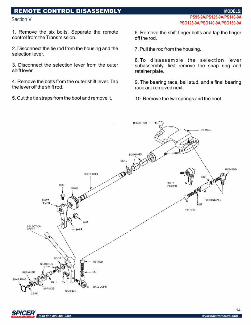
1. Remove the six bolts. Separate the remote control from the Transmission.
2. Disconnect the tie rod from the housing and the selection lever.
3. Disconnect the selection lever from the outer shift lever.
4. Remove the bolts from the outer shift lever. Tap the lever off the shift rod.
5. Cut the tie straps from the boot and remove it.
6. Remove the shift finger bolts and tap the finger off the rod.
7. Pull the rod from the housing.
8.To d isassemble the select ion lever subassembly, first remove the snap ring and retainer plate.
9. The bearing race, ball stud, and a final bearing race are removed next.
10. Remove the two springs and the boot.
MODELS:
PS95-9A/PS125-9A/PS140-9A
PSO125-9A/PSO140-9A/PSO150-9A
14
tech line 800-401-9866 www.ttcautomotive.com
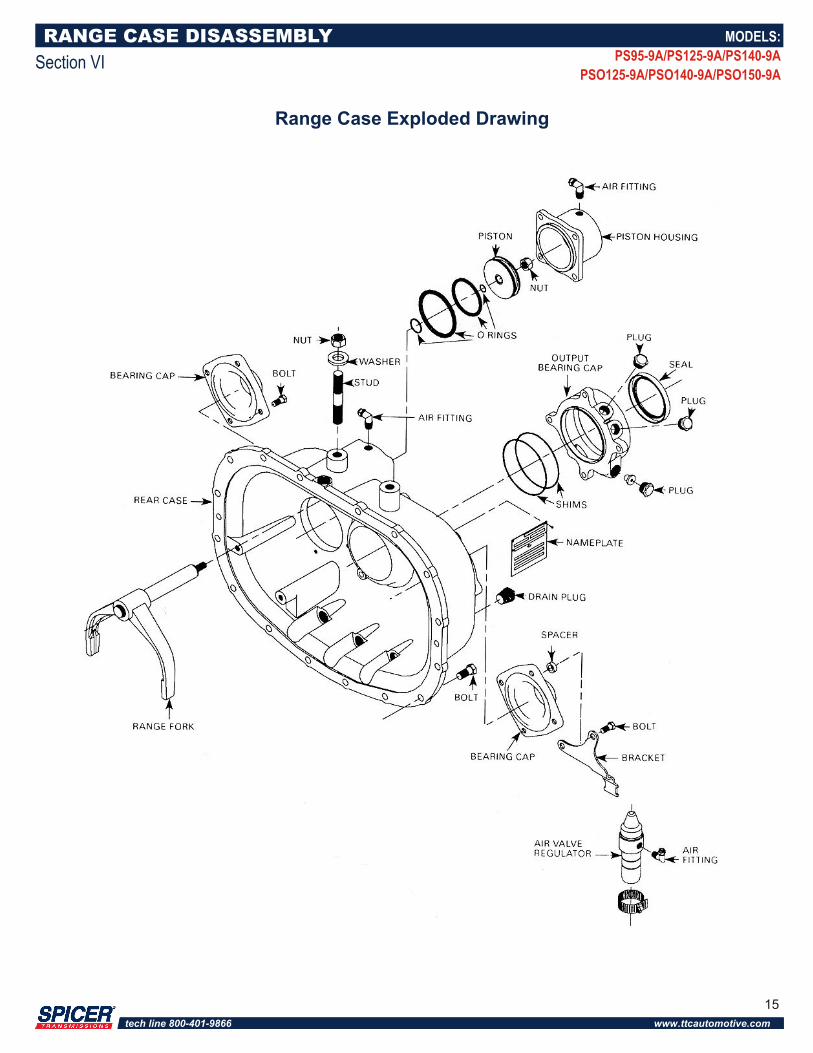
RANGE CASE DISASSEMBLY
Section VI
Range Case Exploded Drawing
MODELS:
PS95-9A/PS125-9A/PS140-9A
PSO125-9A/PSO140-9A/PSO150-9A
15
tech line 800-401-9866 www.ttcautomotive.com
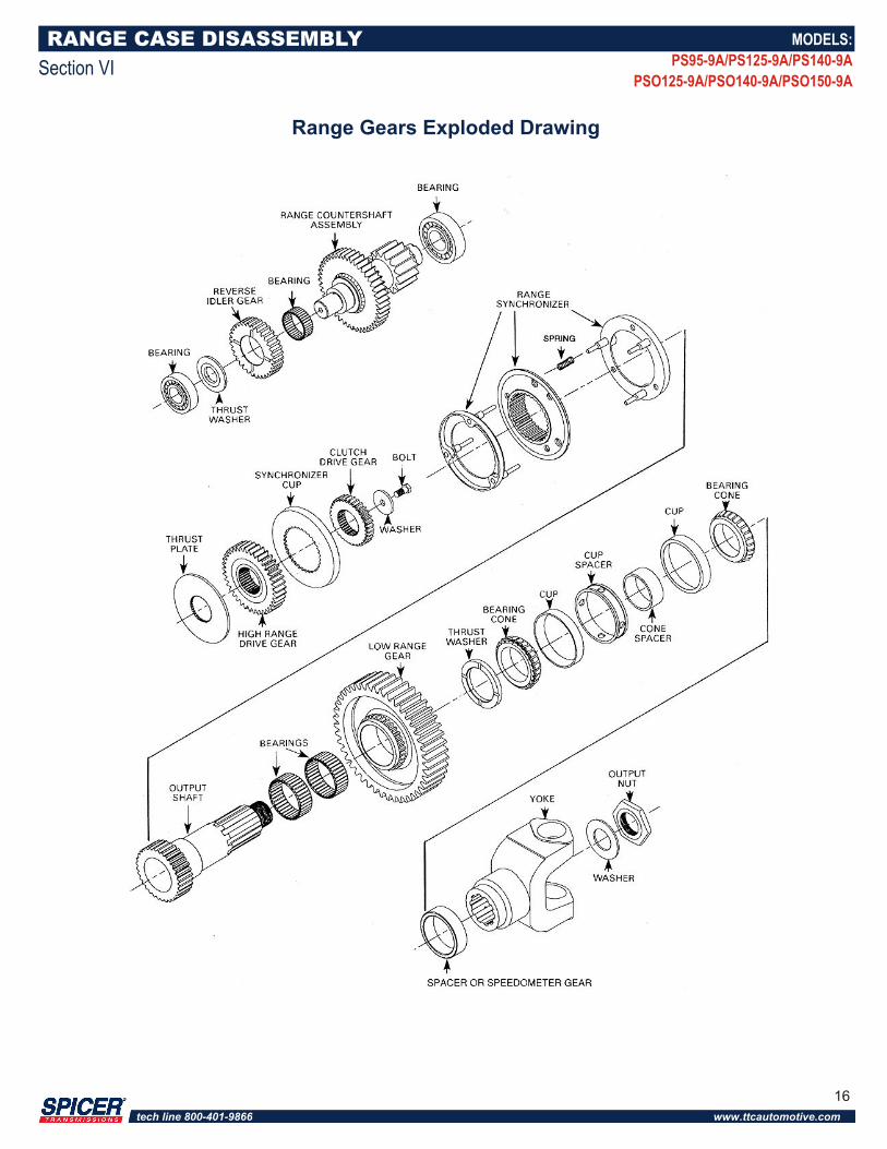
RANGE CASE DISASSEMBLY
Section VI
Range Gears Exploded Drawing
MODELS:
PS95-9A/PS125-9A/PS140-9A
PSO125-9A/PSO140-9A/PSO150-9A
16
tech line 800-401-9866 www.ttcautomotive.com
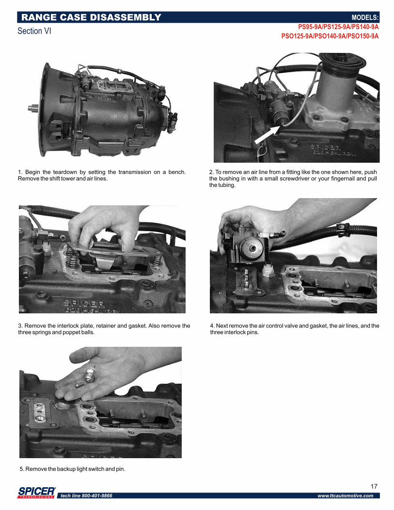
1. Begin the teardown by setting the transmission on a bench. Remove the shift tower and air lines.
2. To remove an air line from a fitting like the one shown here, push the bushing in with a small screwdriver or your fingernail and pull the tubing.
5. Remove the backup light switch and pin.
3. Remove the interlock plate, retainer and gasket. Also remove the three springs and poppet balls.
4. Next remove the air control valve and gasket, the air lines, and the three interlock pins.
RANGE CASE DISASSEMBLY
Section VI
MODELS:
PS95-9A/PS125-9A/PS140-9A
PSO125-9A/PSO140-9A/PSO150-9A
17
tech line 800-401-9866 www.ttcautomotive.com
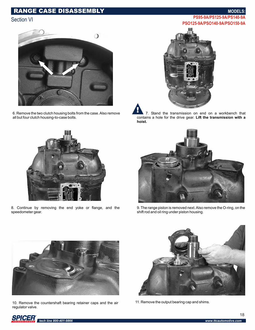
6. Remove the two clutch housing bolts from the case. Also remove all but four clutch housing-to-case bolts.
7. Stand the transmission on end on a workbench that contains a hole for the drive gear. Lift the transmission with a hoist.
8. Continue by removing the end yoke or flange, and the speedometer gear.
9. The range piston is removed next. Also remove the O-ring, on the shift rod and oil ring under piston housing.
10. Remove the countershaft bearing retainer caps and the air regulator valve.
RANGE CASE DISASSEMBLY
Section VI
MODELS:
PS95-9A/PS125-9A/PS140-9A
PSO125-9A/PSO140-9A/PSO150-9A
11. Remove the output bearing cap and shims.
18
tech line 800-401-9866 www.ttcautomotive.com
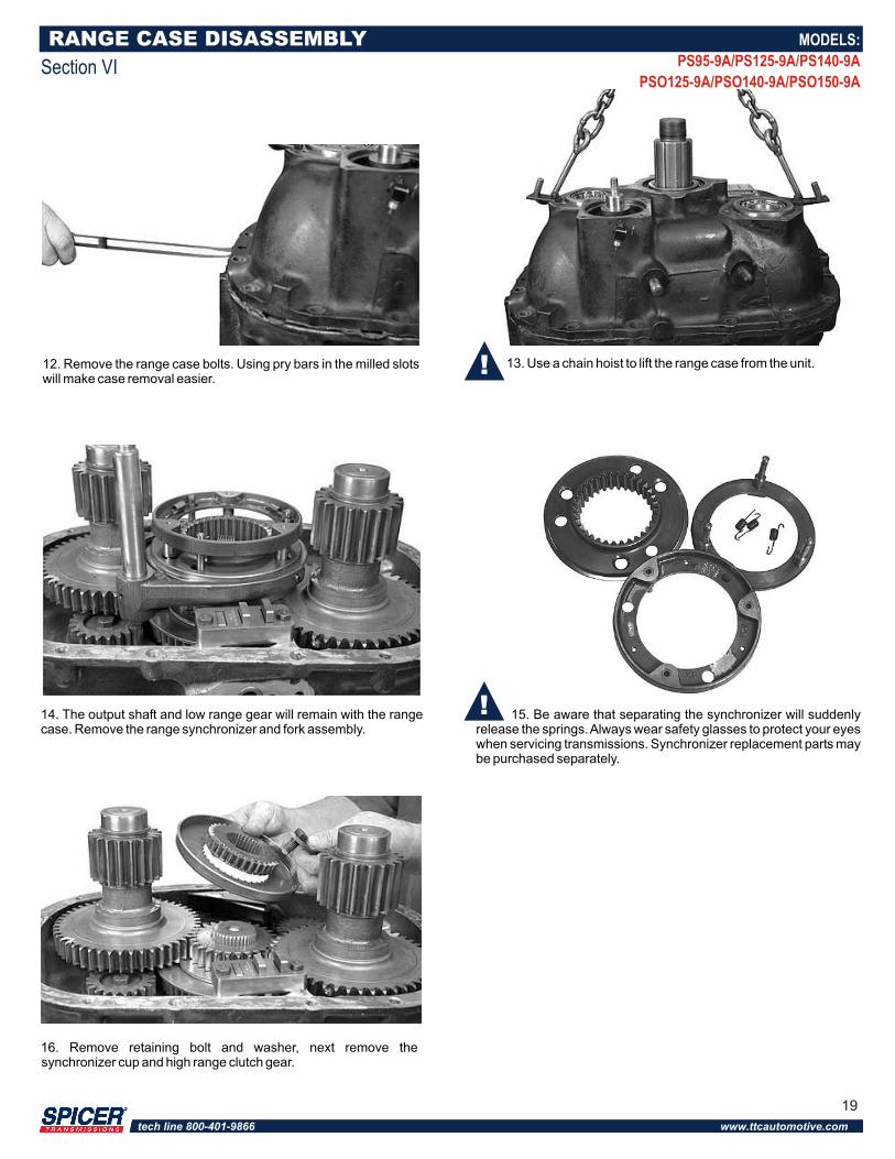
12. Remove the range case bolts. Using pry bars in the milled slots will make case removal easier.
13. Use a chain hoist to lift the range case from the unit.
14. The output shaft and low range gear will remain with the range case. Remove the range synchronizer and fork assembly.
15. Be aware that separating the synchronizer will suddenly release the springs. Always wear safety glasses to protect your eyes when servicing transmissions. Synchronizer replacement parts may be purchased separately.
RANGE CASE DISASSEMBLY
Section VI
16. Remove retaining bolt and washer, next remove the synchronizer cup and high range clutch gear.
MODELS:
PS95-9A/PS125-9A/PS140-9A
PSO125-9A/PSO140-9A/PSO150-9A
19
tech line 800-401-9866 www.ttcautomotive.com
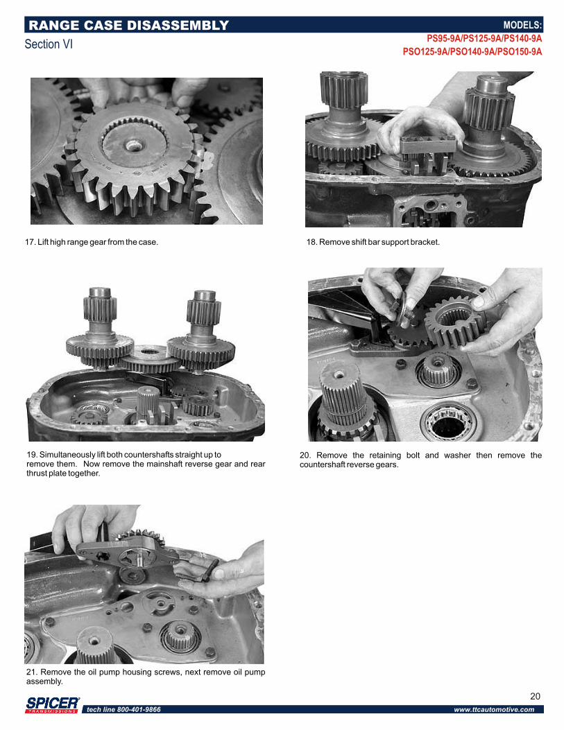
18. Remove shift bar support bracket.
19. Simultaneously lift both countershafts straight up toremove them. Now remove the mainshaft reverse gear and rear thrust plate together.
20. Remove the retaining bolt and washer then remove the countershaft reverse gears.
RANGE CASE DISASSEMBLY
Section VI
17. Lift high range gear from the case.
21. Remove the oil pump housing screws, next remove oil pump assembly.
MODELS:
PS95-9A/PS125-9A/PS140-9A
PSO125-9A/PSO140-9A/PSO150-9A
20
tech line 800-401-9866 www.ttcautomotive.com
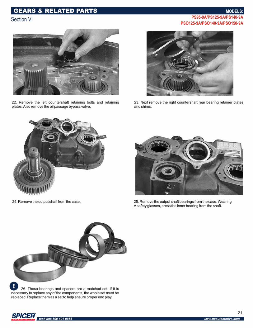
22. Remove the left countershaft retaining bolts and retaining plates. Also remove the oil passage bypass valve.
23. Next remove the right countershaft rear bearing retainer plates and shims.
25. Remove the output shaft bearings from the case. Wearing A safety glasses, press the inner bearing from the shaft.
26. These bearings and spacers are a matched set. If it is necessary to replace any of the components, the whole set must be replaced. Replace them as a set to help ensure proper end play.
GEARS & RELATED PARTS
Section VI
MODELS:
PS95-9A/PS125-9A/PS140-9A
PSO125-9A/PSO140-9A/PSO150-9A
24. Remove the output shaft from the case.
21
tech line 800-401-9866 www.ttcautomotive.com
MAIN CASE DISASSEMBLY
Section VII
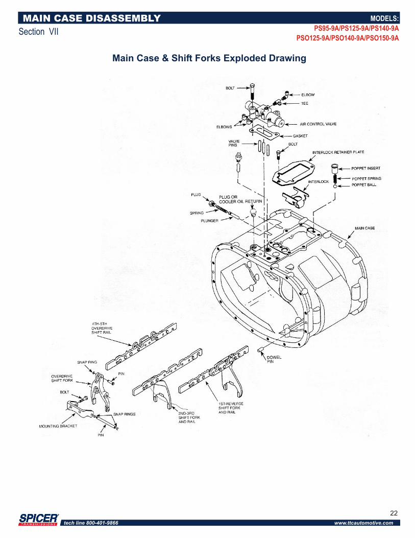
Main Case & Shift Forks Exploded Drawing
MODELS:
PS95-9A/PS125-9A/PS140-9A
PSO125-9A/PSO140-9A/PSO150-9A
22
tech line 800-401-9866 www.ttcautomotive.com
MAIN CASE DISASSEMBLY
Section VII
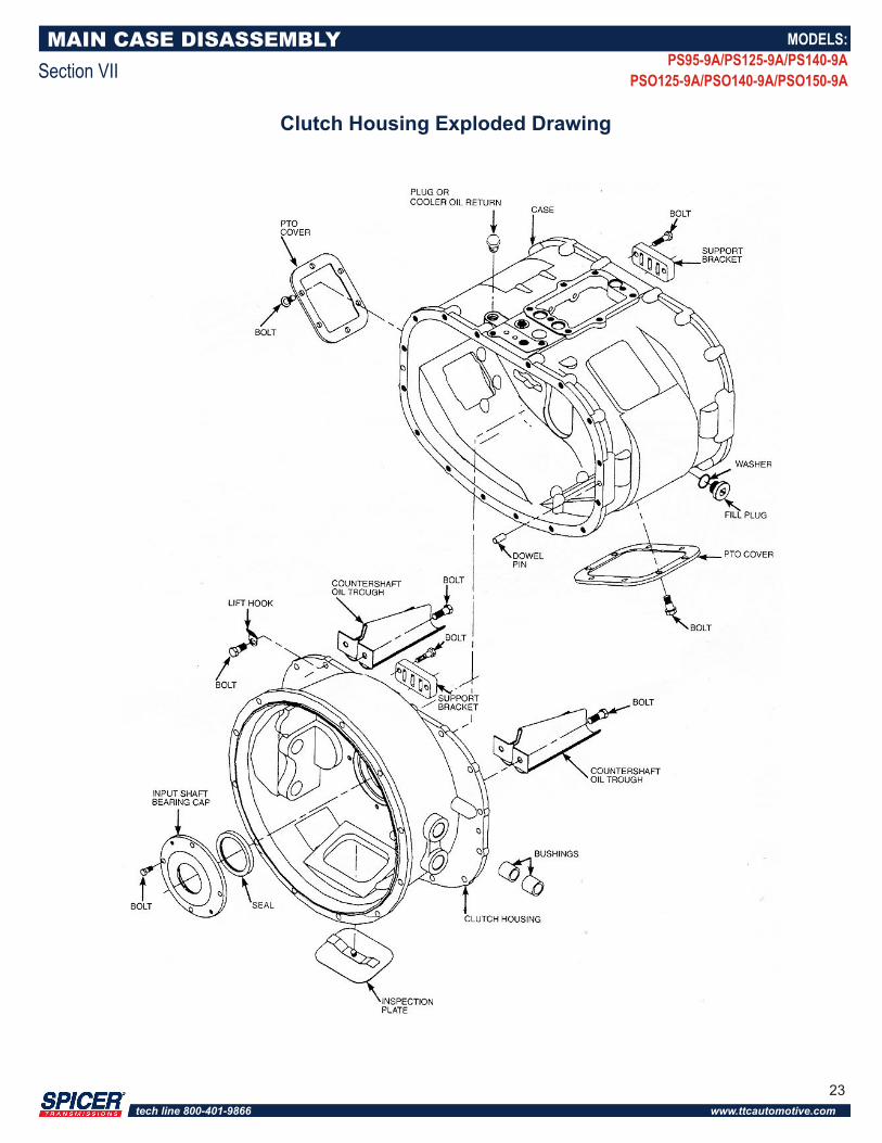
Clutch Housing Exploded Drawing
MODELS:
PS95-9A/PS125-9A/PS140-9A
PSO125-9A/PSO140-9A/PSO150-9A
23
tech line 800-401-9866 www.ttcautomotive.com
MAIN CASE DISASSEMBLY
Section VII
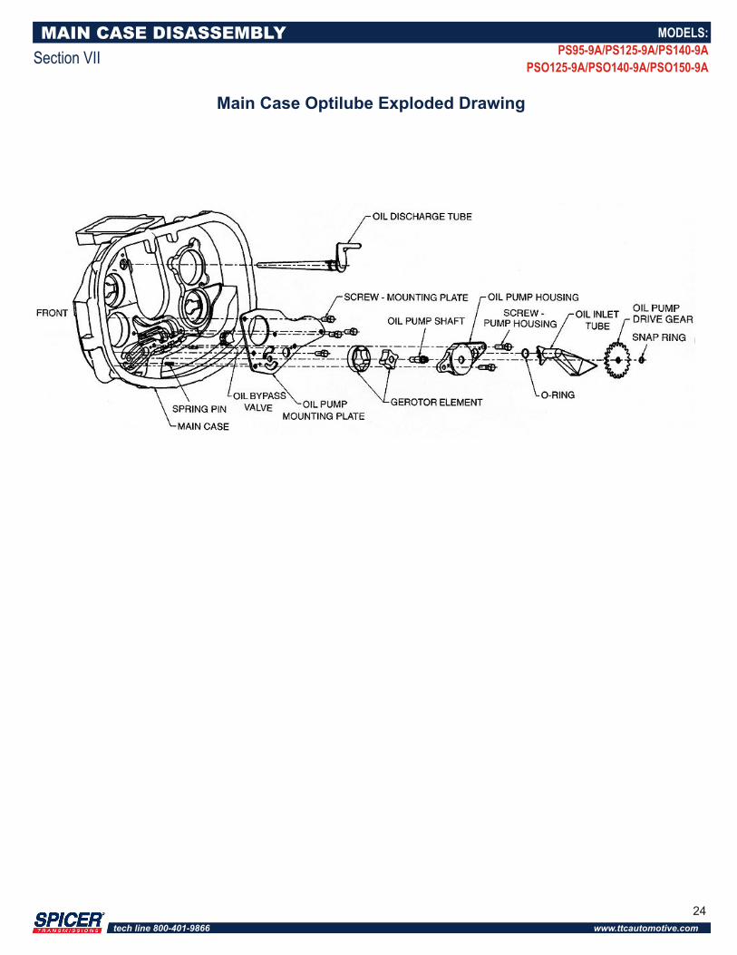
Main Case Optilube Exploded Drawing
MODELS:
PS95-9A/PS125-9A/PS140-9A
PSO125-9A/PSO140-9A/PSO150-9A
24
tech line 800-401-9866 www.ttcautomotive.com
MAIN CASE DISASSEMBLY
Section VII
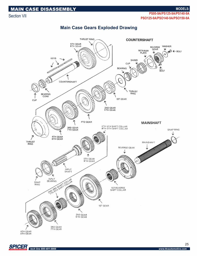
Main Case Gears Exploded Drawing
MODELS:
PS95-9A/PS125-9A/PS140-9A
PSO125-9A/PSO140-9A/PSO150-9A
25
tech line 800-401-9866 www.ttcautomotive.com
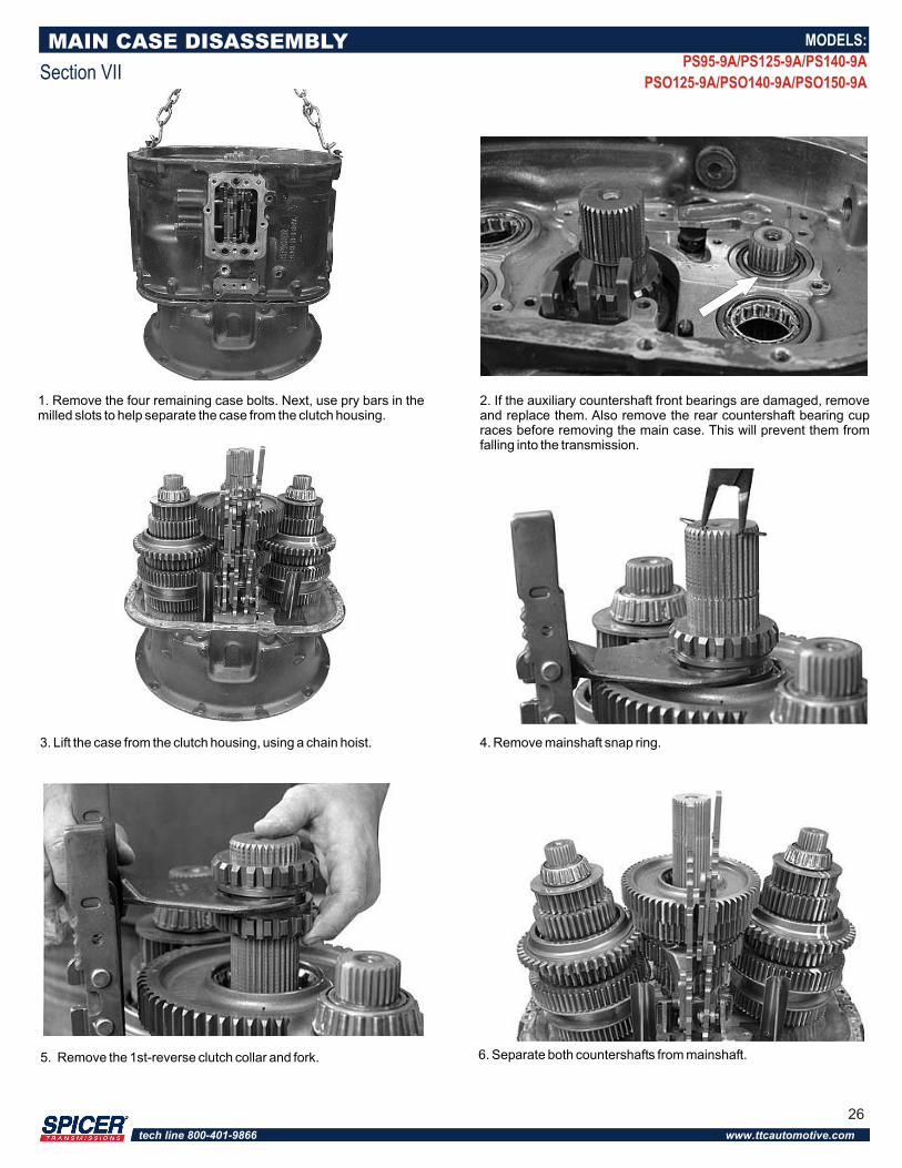
1. Remove the four remaining case bolts. Next, use pry bars in the milled slots to help separate the case from the clutch housing.
2. If the auxiliary countershaft front bearings are damaged, remove and replace them. Also remove the rear countershaft bearing cup races before removing the main case. This will prevent them from falling into the transmission.
3. Lift the case from the clutch housing, using a chain hoist. 4. Remove mainshaft snap ring.
5. Remove the 1st-reverse clutch collar and fork. 6. Separate both countershafts from mainshaft.
MAIN CASE DISASSEMBLY
Section VII
MODELS:
PS95-9A/PS125-9A/PS140-9A
PSO125-9A/PSO140-9A/PSO150-9A
26
tech line 800-401-9866 www.ttcautomotive.com
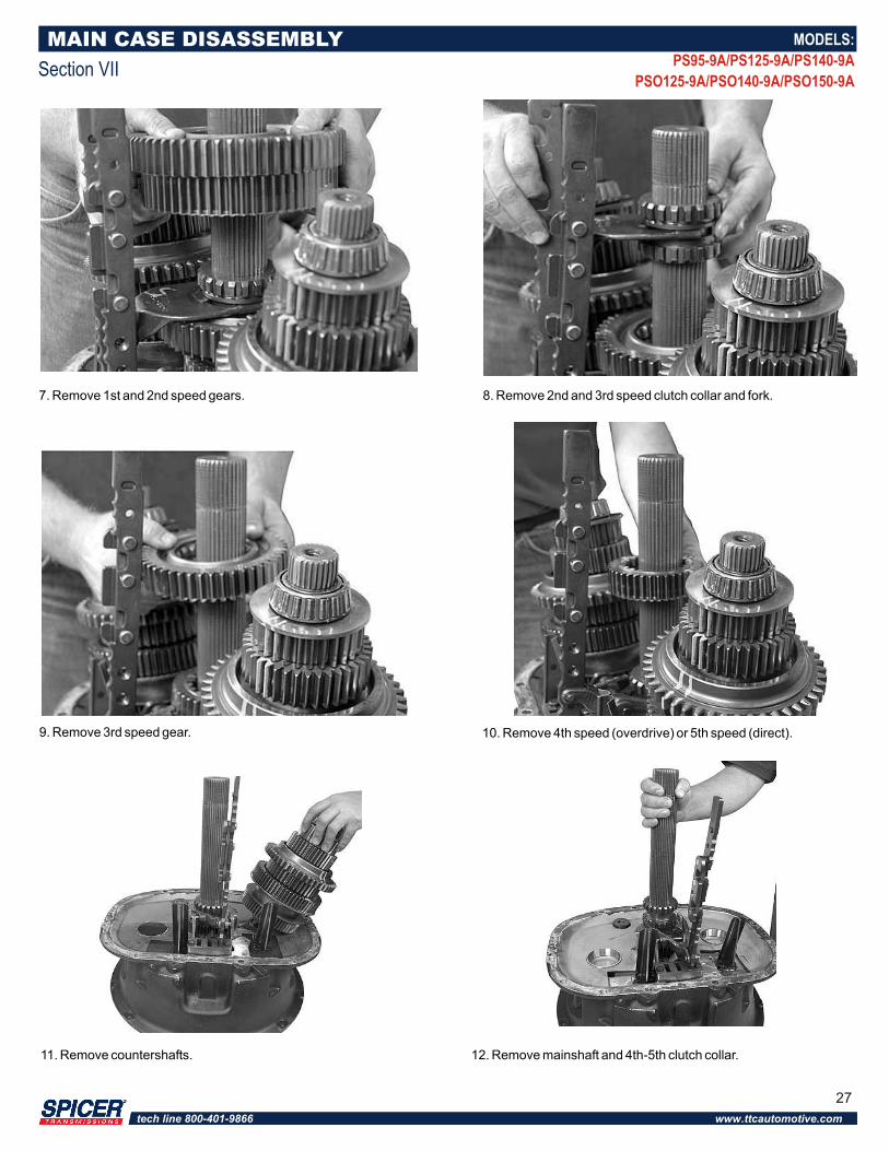
7. Remove 1st and 2nd speed gears. 8. Remove 2nd and 3rd speed clutch collar and fork.
9. Remove 3rd speed gear. 10. Remove 4th speed (overdrive) or 5th speed (direct).
11. Remove countershafts. 12. Remove mainshaft and 4th-5th clutch collar.
MAIN CASE DISASSEMBLY
Section VII
MODELS:
PS95-9A/PS125-9A/PS140-9A
PSO125-9A/PSO140-9A/PSO150-9A
27
tech line 800-401-9866 www.ttcautomotive.com
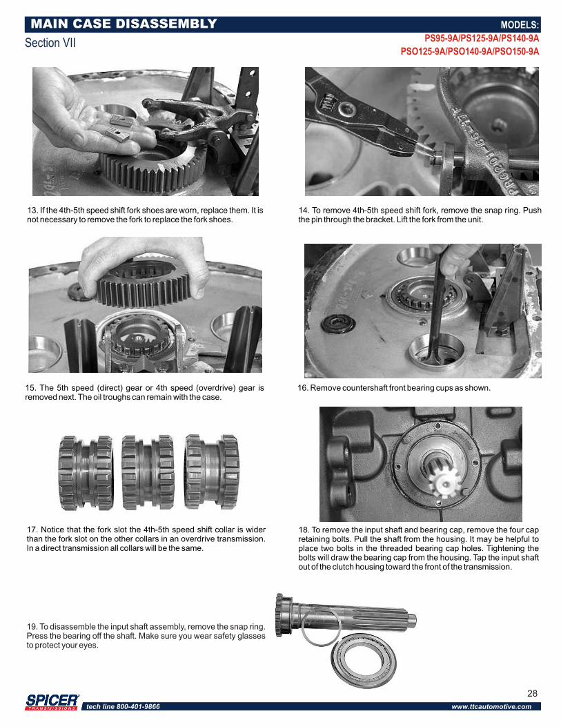
18. To remove the input shaft and bearing cap, remove the four cap retaining bolts. Pull the shaft from the housing. It may be helpful to place two bolts in the threaded bearing cap holes. Tightening the bolts will draw the bearing cap from the housing. Tap the input shaft out of the clutch housing toward the front of the transmission.
MAIN CASE DISASSEMBLY
Section VII
13. If the 4th-5th speed shift fork shoes are worn, replace them. It is not necessary to remove the fork to replace the fork shoes.
14. To remove 4th-5th speed shift fork, remove the snap ring. Push the pin through the bracket. Lift the fork from the unit.
15. The 5th speed (direct) gear or 4th speed (overdrive) gear is removed next. The oil troughs can remain with the case.
16. Remove countershaft front bearing cups as shown.
17. Notice that the fork slot the 4th-5th speed shift collar is wider than the fork slot on the other collars in an overdrive transmission. In a direct transmission all collars will be the same.
MODELS:
PS95-9A/PS125-9A/PS140-9A
PSO125-9A/PSO140-9A/PSO150-9A
19. To disassemble the input shaft assembly, remove the snap ring. Press the bearing off the shaft. Make sure you wear safety glasses to protect your eyes.
28
tech line 800-401-9866 www.ttcautomotive.com
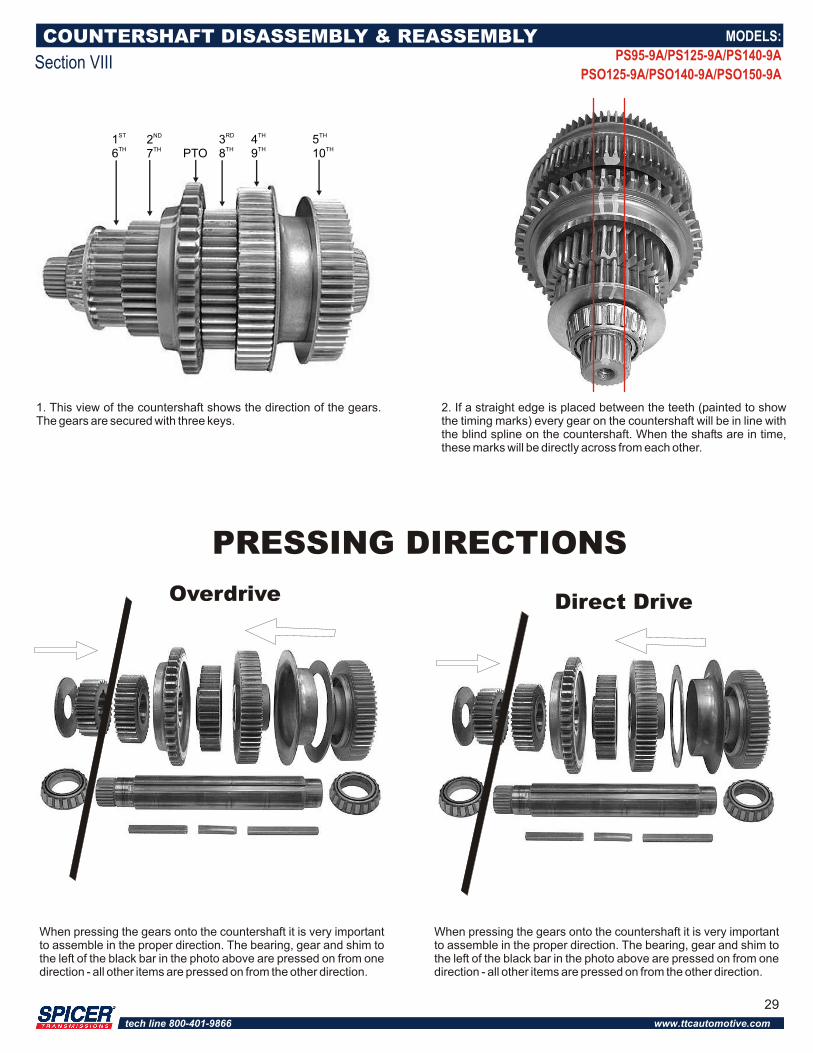
1. This view of the countershaft shows the direction of the gears. The gears are secured with three keys.
COUNTERSHAFT DISASSEMBLY & REASSEMBLY
Section VIII
2. If a straight edge is placed between the teeth (painted to show the timing marks) every gear on the countershaft will be in line with the blind spline on the countershaft. When the shafts are in time, these marks will be directly across from each other.
ST1TH6
ND2TH7 PTO
RD3TH8
TH5TH10
TH4TH9
MODELS:
PS95-9A/PS125-9A/PS140-9A
PSO125-9A/PSO140-9A/PSO150-9A
29
Overdrive Direct Drive
PRESSING DIRECTIONS
When pressing the gears onto the countershaft it is very important to assemble in the proper direction. The bearing, gear and shim to the left of the black bar in the photo above are pressed on from one direction - all other items are pressed on from the other direction.
When pressing the gears onto the countershaft it is very important to assemble in the proper direction. The bearing, gear and shim to the left of the black bar in the photo above are pressed on from one direction - all other items are pressed on from the other direction.
tech line 800-401-9866 www.ttcautomotive.com
CLEANING & INSPECTION PROCEDURES
Section IX
Cleaning
Prior to reassembly, wash all parts thoroughly.
Use a petroleum-based solvent. Refer to the solvent manufacturer's safety precautions to prevent personal injury or transmission damage.
Do not use water or steam to clean internal components. If you do, it could cause corrosion of these components.
Do not use gasoline to clean parts. Gasoline can explode, causing serious physical injury.
Dry the parts immediately with compressed air. Coat them with lubricant if they are to be reassembled immediately. If the parts are to be stored, coat them with a rust inhibitor and wrap them to keep contamination out.
Inspect parts thoroughly for wear or damage. Parts damaged or worn from previous service must be replaced to insure maximum rebuild life. Suggested inspection procedures include the following.
InspectionClutch Collars
Both the internal and external teeth must have sharp edges. Check for chipped or broken teeth, or teeth with rounded corners. Also, examine fork slots for wear. Replace collars if any of these conditions exist.
Gears
Examine for broken or cracked operating and clutching teeth. Also check for any unusual wear patterns. If any of the preceding exists, replace the gear. If a gear is replaced, also replace the mating gear.
Thrust Washers
Check for flatness or excessive face wear, cracks, scoring, or signs of heat damage. Replace if any of these conditions exists.
Snap Rings
New snap rings are recommended with every rebuild.
Mainshaft
Check for signs of twisting or misalignment. Also check for worn or damaged splines. Replace the shaft if any of these conditions exists.
Remote Control
Check the shift fingers, bushing bores and rods for excessive wear or scuffing. Replace springs, bearing races, boots and seals. Clean all reusable parts thoroughly and apply a light coat of grease to the pivot points when reassembling.
Bearings
New bearings are recommended with every rebuild. (See "General Disassembly Bearings" for further information.)
Housings
Inspect the housing sections for cracks. If cracks exist, replace that section of the housing. Also inspect the shift bar support bracket for cracks or worn slots. Replace if either of these conditions exists.
MODELS:
PS95-9A/PS125-9A/PS140-9A
PSO125-9A/PSO140-9A/PSO150-9A
30
tech line 800-401-9866 www.ttcautomotive.com
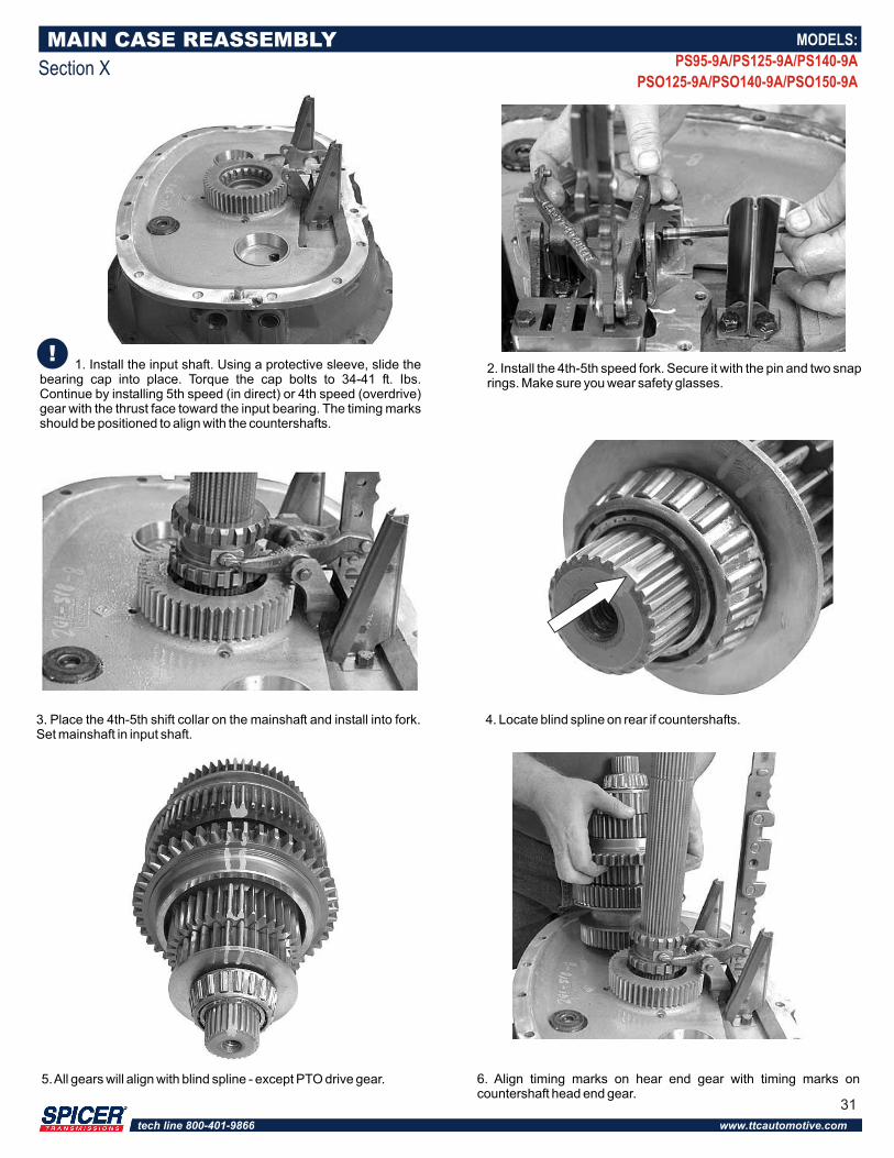
1. Install the input shaft. Using a protective sleeve, slide the bearing cap into place. Torque the cap bolts to 34-41 ft. Ibs. Continue by installing 5th speed (in direct) or 4th speed (overdrive) gear with the thrust face toward the input bearing. The timing marks should be positioned to align with the countershafts.
2. Install the 4th-5th speed fork. Secure it with the pin and two snap rings. Make sure you wear safety glasses.
6. Align timing marks on hear end gear with timing marks on countershaft head end gear.
MAIN CASE REASSEMBLY
Section X
3. Place the 4th-5th shift collar on the mainshaft and install into fork. Set mainshaft in input shaft.
4. Locate blind spline on rear if countershafts.
5. All gears will align with blind spline - except PTO drive gear.
MODELS:
PS95-9A/PS125-9A/PS140-9A
PSO125-9A/PSO140-9A/PSO150-9A
31
tech line 800-401-9866 www.ttcautomotive.com
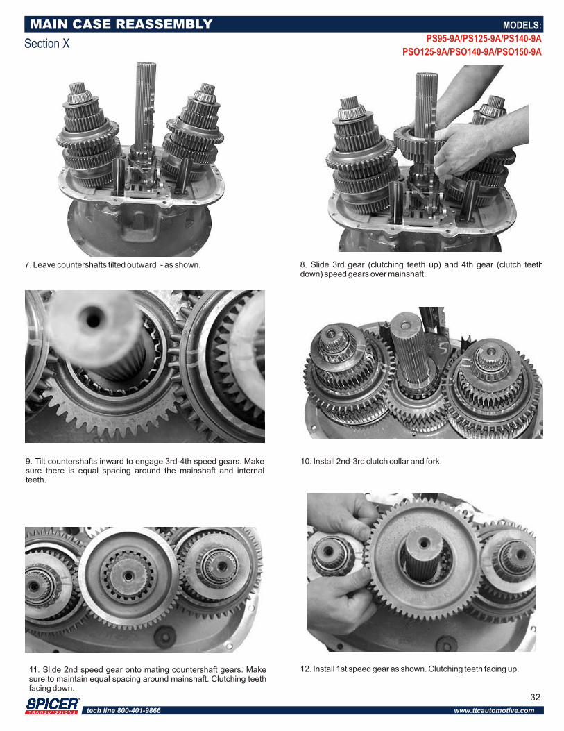
8. Slide 3rd gear (clutching teeth up) and 4th gear (clutch teeth down) speed gears over mainshaft.
MAIN CASE REASSEMBLY
Section X
MODELS:
PS95-9A/PS125-9A/PS140-9A
PSO125-9A/PSO140-9A/PSO150-9A
9. Tilt countershafts inward to engage 3rd-4th speed gears. Make sure there is equal spacing around the mainshaft and internal teeth.
10. Install 2nd-3rd clutch collar and fork.
11. Slide 2nd speed gear onto mating countershaft gears. Make sure to maintain equal spacing around mainshaft. Clutching teeth facing down.
12. Install 1st speed gear as shown. Clutching teeth facing up.
7. Leave countershafts tilted outward - as shown.
5810
32
tech line 800-401-9866 www.ttcautomotive.com
MAIN CASE REASSEMBLY
Section X
MODELS:
PS95-9A/PS125-9A/PS140-9A
PSO125-9A/PSO140-9A/PSO150-9A
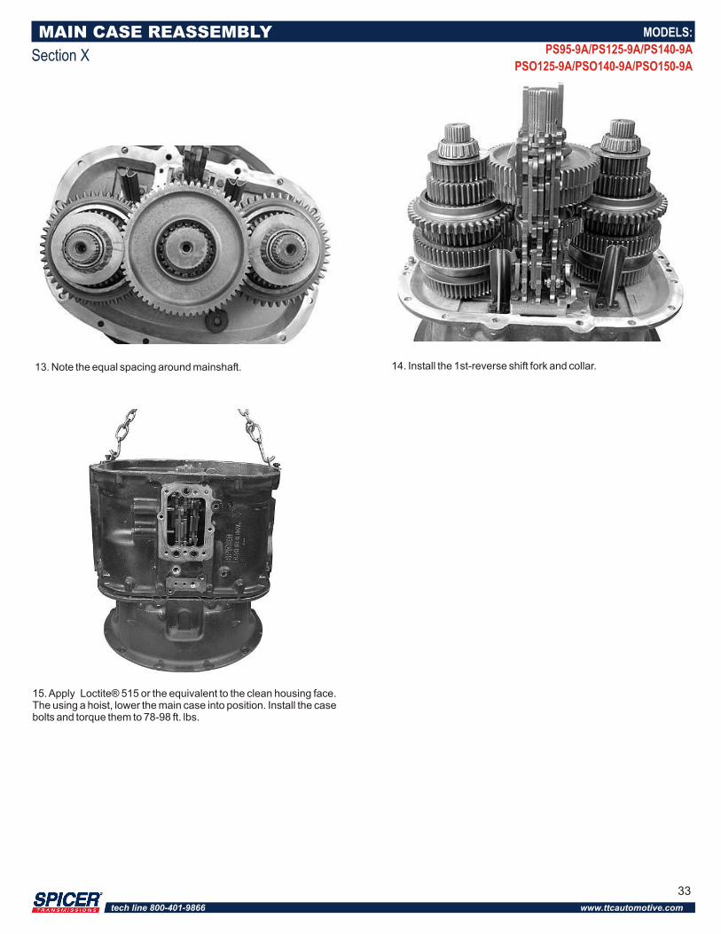
13. Note the equal spacing around mainshaft. 14. Install the 1st-reverse shift fork and collar.
15. Apply Loctite® 515 or the equivalent to the clean housing face. The using a hoist, lower the main case into position. Install the case bolts and torque them to 78-98 ft. lbs.
33
tech line 800-401-9866 www.ttcautomotive.com
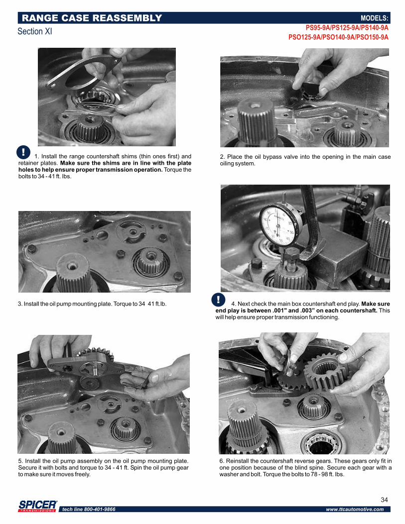
1. Install the range countershaft shims (thin ones first) and retainer plates. Make sure the shims are in line with the plate holes to help ensure proper transmission operation. Torque the bolts to 34 - 41 ft. Ibs.
4. Next check the main box countershaft end play. Make sure end play is between .001" and .003” on each countershaft. This will help ensure proper transmission functioning.
6. Reinstall the countershaft reverse gears. These gears only fit in one position because of the blind spine. Secure each gear with a washer and bolt. Torque the bolts to 78 - 98 ft. Ibs.
5. Install the oil pump assembly on the oil pump mounting plate. Secure it with bolts and torque to 34 - 41 ft. Spin the oil pump gear to make sure it moves freely.
RANGE CASE REASSEMBLY
Section XI
2. Place the oil bypass valve into the opening in the main case oiling system.
3. Install the oil pump mounting plate. Torque to 34 41 ft.lb.
MODELS:
PS95-9A/PS125-9A/PS140-9A
PSO125-9A/PSO140-9A/PSO150-9A
34
tech line 800-401-9866 www.ttcautomotive.com
RANGE CASE REASSEMBLY
Section XI
MODELS:
PS95-9A/PS125-9A/PS140-9A
PSO125-9A/PSO140-9A/PSO150-9A
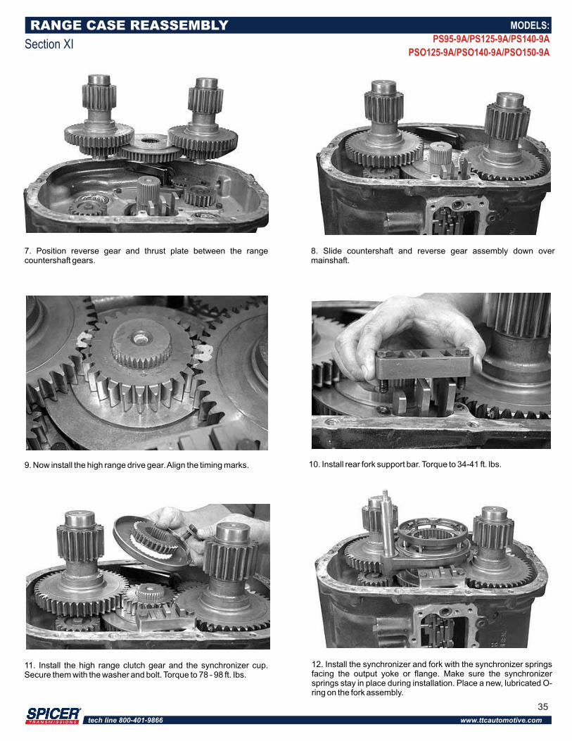
7. Position reverse gear and thrust plate between the range countershaft gears.
8. Slide countershaft and reverse gear assembly down over mainshaft.
9. Now install the high range drive gear. Align the timing marks. 10. Install rear fork support bar. Torque to 34-41 ft. lbs.
12. Install the synchronizer and fork with the synchronizer springs facing the output yoke or flange. Make sure the synchronizer springs stay in place during installation. Place a new, lubricated O-ring on the fork assembly.
11. Install the high range clutch gear and the synchronizer cup. Secure them with the washer and bolt. Torque to 78 - 98 ft. Ibs.
35
tech line 800-401-9866 www.ttcautomotive.com
RANGE CASE REASSEMBLY
Section XI
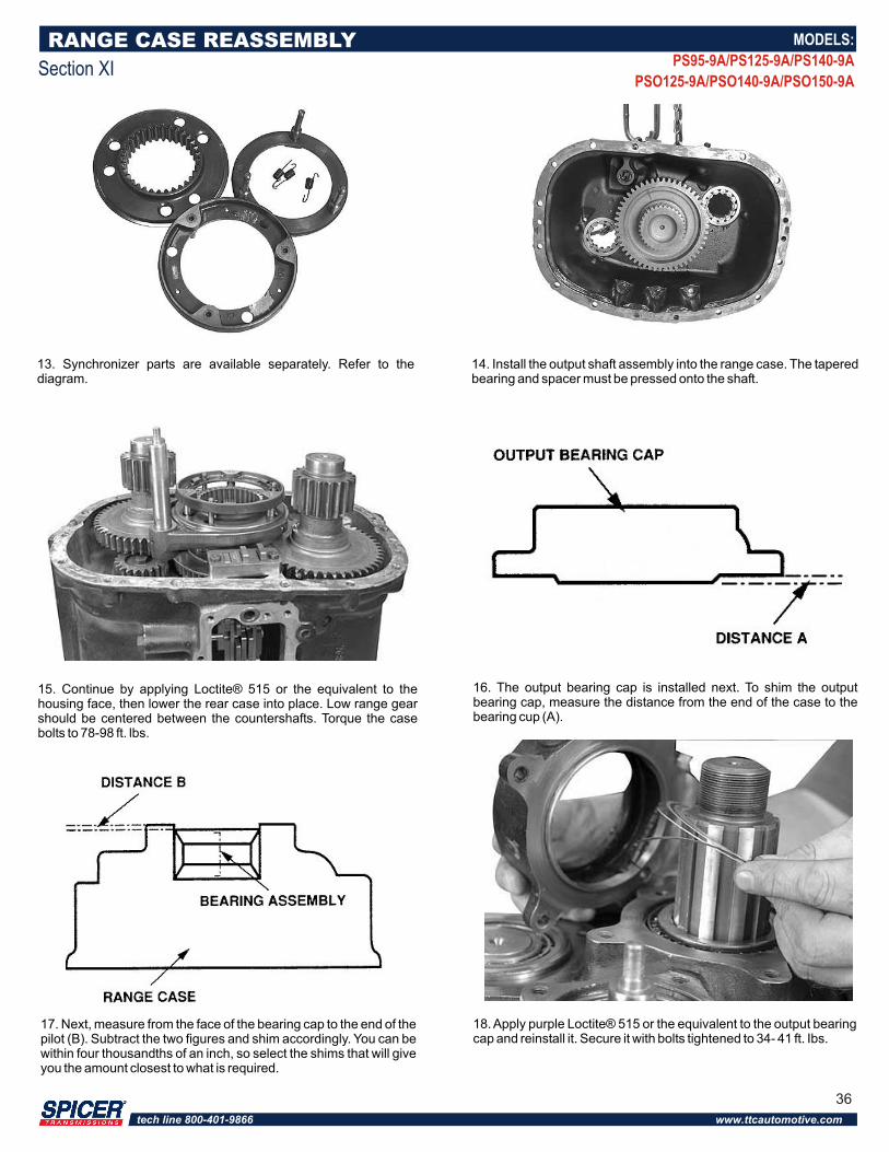
13. Synchronizer parts are available separately. Refer to the diagram.
14. Install the output shaft assembly into the range case. The tapered bearing and spacer must be pressed onto the shaft.
15. Continue by applying Loctite® 515 or the equivalent to the housing face, then lower the rear case into place. Low range gear should be centered between the countershafts. Torque the case bolts to 78-98 ft. lbs.
MODELS:
PS95-9A/PS125-9A/PS140-9A
PSO125-9A/PSO140-9A/PSO150-9A
17. Next, measure from the face of the bearing cap to the end of the pilot (B). Subtract the two figures and shim accordingly. You can be within four thousandths of an inch, so select the shims that will give you the amount closest to what is required.
16. The output bearing cap is installed next. To shim the output bearing cap, measure the distance from the end of the case to the bearing cup (A).
18. Apply purple Loctite® 515 or the equivalent to the output bearing cap and reinstall it. Secure it with bolts tightened to 34- 41 ft. Ibs.
36
tech line 800-401-9866 www.ttcautomotive.com
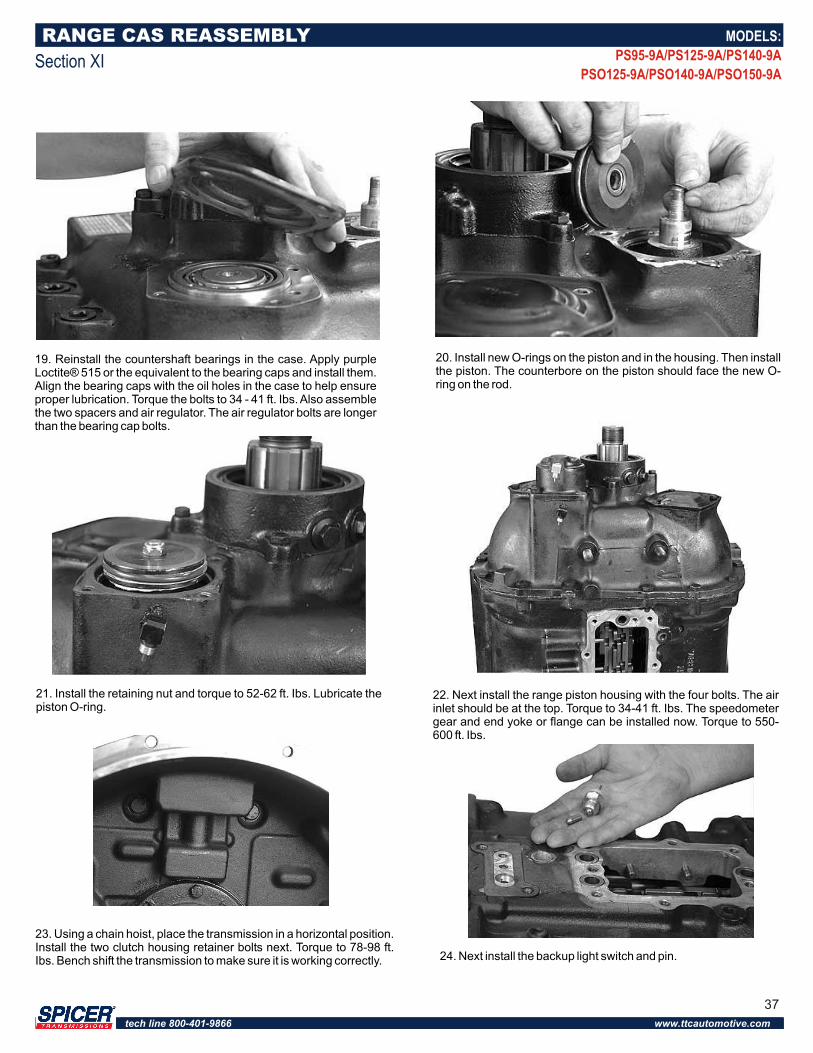
19. Reinstall the countershaft bearings in the case. Apply purple Loctite® 515 or the equivalent to the bearing caps and install them. Align the bearing caps with the oil holes in the case to help ensure proper lubrication. Torque the bolts to 34 - 41 ft. Ibs. Also assemble the two spacers and air regulator. The air regulator bolts are longer than the bearing cap bolts.
20. Install new O-rings on the piston and in the housing. Then install the piston. The counterbore on the piston should face the new O-ring on the rod.
RANGE CAS REASSEMBLY
Section XI
MODELS:
PS95-9A/PS125-9A/PS140-9A
PSO125-9A/PSO140-9A/PSO150-9A
21. Install the retaining nut and torque to 52-62 ft. Ibs. Lubricate the piston O-ring.
22. Next install the range piston housing with the four bolts. The air inlet should be at the top. Torque to 34-41 ft. Ibs. The speedometer gear and end yoke or flange can be installed now. Torque to 550-600 ft. Ibs.
23. Using a chain hoist, place the transmission in a horizontal position. Install the two clutch housing retainer bolts next. Torque to 78-98 ft. Ibs. Bench shift the transmission to make sure it is working correctly. 24. Next install the backup light switch and pin.
37
tech line 800-401-9866 www.ttcautomotive.com
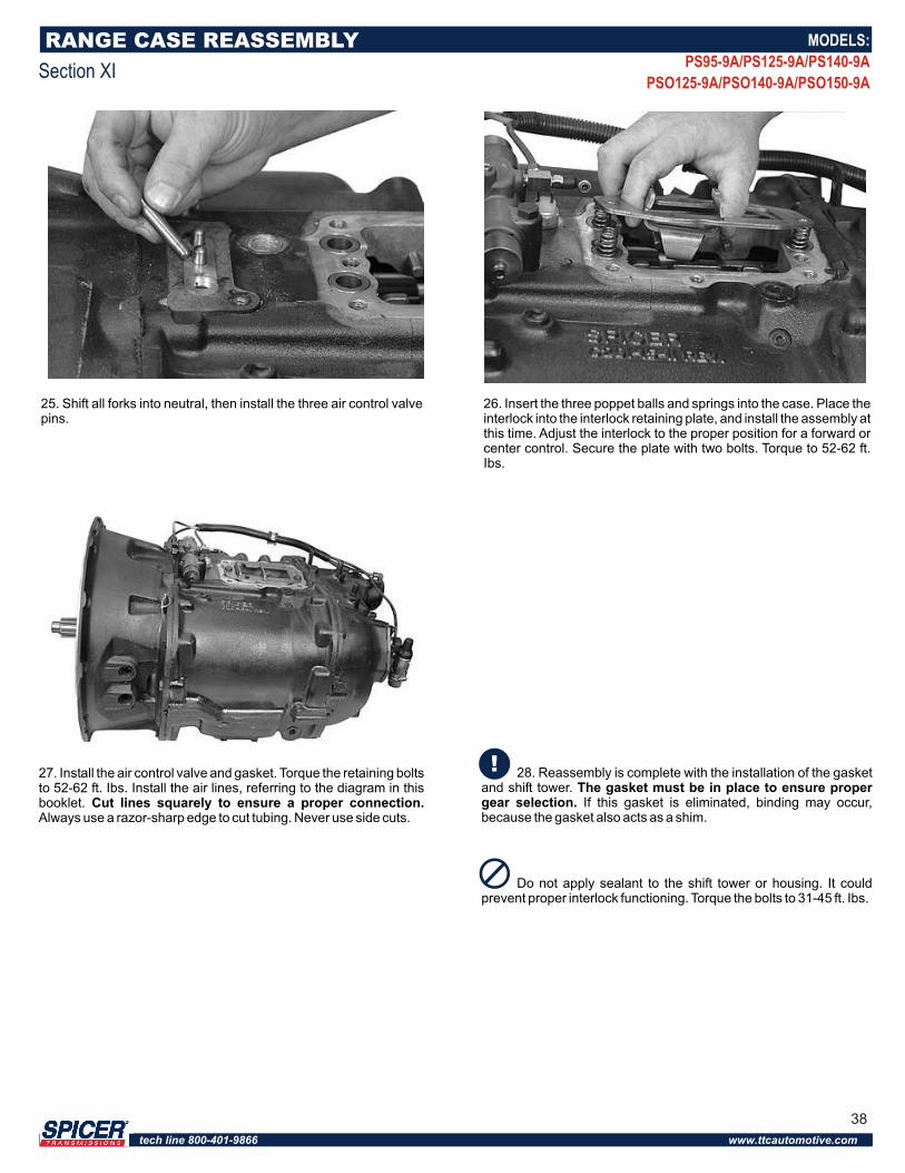
25. Shift all forks into neutral, then install the three air control valve pins.
RANGE CASE REASSEMBLY
Section XI
MODELS:
PS95-9A/PS125-9A/PS140-9A
PSO125-9A/PSO140-9A/PSO150-9A
26. Insert the three poppet balls and springs into the case. Place the interlock into the interlock retaining plate, and install the assembly at this time. Adjust the interlock to the proper position for a forward or center control. Secure the plate with two bolts. Torque to 52-62 ft. Ibs.
28. Reassembly is complete with the installation of the gasket and shift tower. The gasket must be in place to ensure proper gear selection. If this gasket is eliminated, binding may occur, because the gasket also acts as a shim.
Do not apply sealant to the shift tower or housing. It could prevent proper interlock functioning. Torque the bolts to 31-45 ft. Ibs.
27. Install the air control valve and gasket. Torque the retaining bolts to 52-62 ft. Ibs. Install the air lines, referring to the diagram in this booklet. Cut lines squarely to ensure a proper connection. Always use a razor-sharp edge to cut tubing. Never use side cuts.
38
tech line 800-401-9866 www.ttcautomotive.com
REMOTE CONTROL REASSEMBLY
Section XII
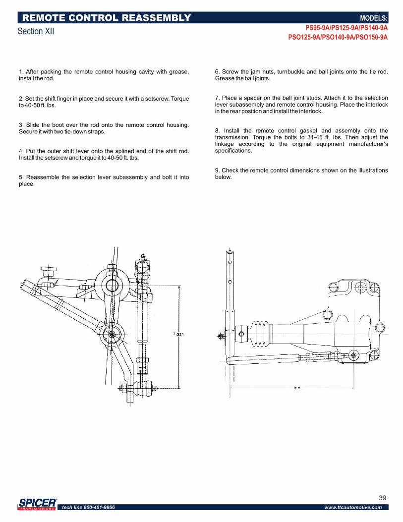
1. After packing the remote control housing cavity with grease, install the rod.
2. Set the shift finger in place and secure it with a setscrew. Torque to 40-50 ft. ibs.
3. Slide the boot over the rod onto the remote control housing. Secure it with two tie-down straps.
4. Put the outer shift lever onto the splined end of the shift rod. Install the setscrew and torque it to 40-50 ft. tbs.
5. Reassemble the selection lever subassembly and bolt it into place.
6. Screw the jam nuts, turnbuckle and ball joints onto the tie rod. Grease the ball joints.
7. Place a spacer on the ball joint studs. Attach it to the selection lever subassembly and remote control housing. Place the interlock in the rear position and install the interlock.
8. Install the remote control gasket and assembly onto the transmission. Torque the bolts to 31-45 ft. Ibs. Then adjust the linkage according to the original equipment manufacturer's specifications.
9. Check the remote control dimensions shown on the illustrations below.
MODELS:
PS95-9A/PS125-9A/PS140-9A
PSO125-9A/PSO140-9A/PSO150-9A
39
tech line 800-401-9866 www.ttcautomotive.com
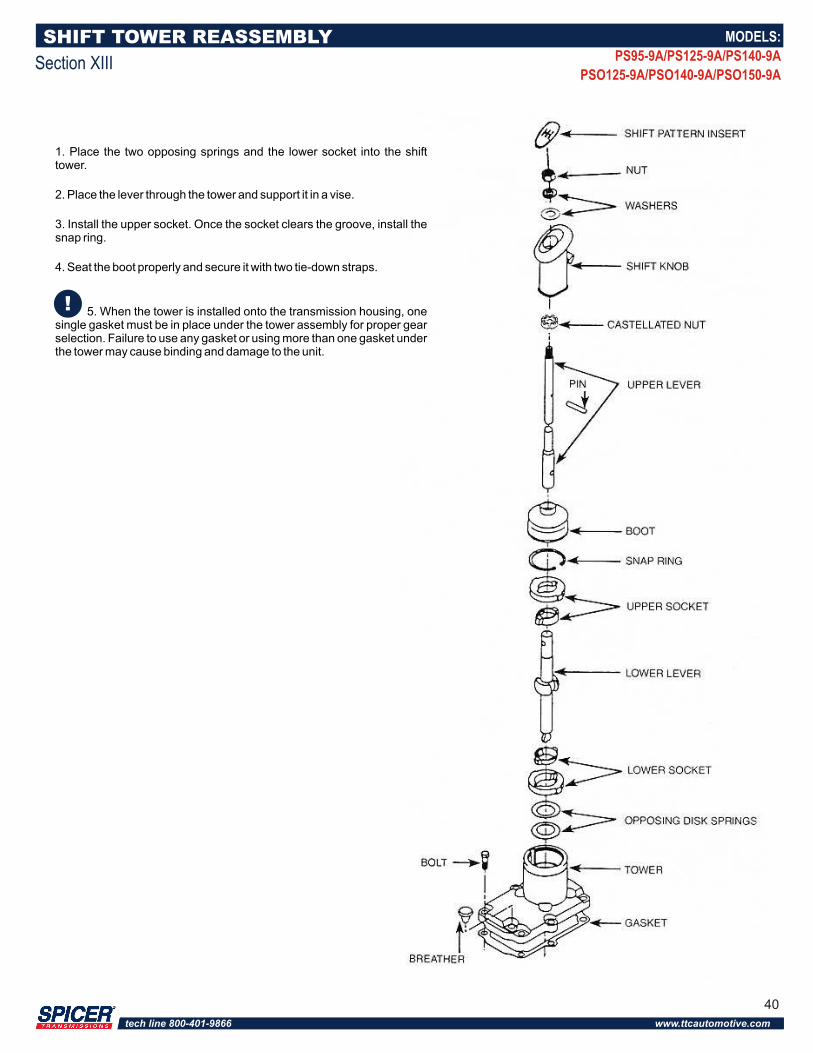
1. Place the two opposing springs and the lower socket into the shift tower.
2. Place the lever through the tower and support it in a vise.
3. Install the upper socket. Once the socket clears the groove, install the snap ring.
4. Seat the boot properly and secure it with two tie-down straps.
5. When the tower is installed onto the transmission housing, one single gasket must be in place under the tower assembly for proper gear selection. Failure to use any gasket or using more than one gasket under the tower may cause binding and damage to the unit.
SHIFT TOWER REASSEMBLY
Section XIII
MODELS:
PS95-9A/PS125-9A/PS140-9A
PSO125-9A/PSO140-9A/PSO150-9A
40
tech line 800-401-9866 www.ttcautomotive.com
TROUBLESHOOTING
Section XIV
Mechanics should try to locate and eliminate noise by means other than a transmission removal or an overhaul. However, if the noise appears to be in the transmission, try to determine what position the gear shift lever is in when the noise occurs. If the noise is evident in only one gear position, the problem is generally traceable to the operating gears. Next, try to categorize the noise into the following classifications:
(A) Growling, humming and grinding. These noises are caused by worn, chipped, rough or cracked gears. As gears continue to wear, the grinding noise will be noticeable particularly in the gear position that throws the greatest load on the worn gear. A lack of lubricant or use of improper lubricant can also result in growling and grinding noises. This is because there is insufficient lubricant to cool and cover the gears, which allows metal-to-metal contact.
(B) Hissing, thumping and bumping. Hissing noises can becaused by bad bearings. As bearings wear and retainers start to break up, etc., the noise could change to a thumping or bumping.
(C) Gear whine. This is usually caused by lack of backlash between mating gears. Improper PTO shimming is the big offender here.
(D) Vibration. Today's improved highways mean entire power trains are cruising at higher RPM's. These higher speeds mean damage caused by driveline vibration is more obvious than in the past. When the maximum RPM of a shaft is reached, it begins to bow. A resonant hum can be heard, and a vibration will be set up. This type vibration can cause gear seizures, broken synchronizer pins, bearing failures, brinelling and corrosion. During acceleration and deceleration, the shaft may pass through half-critical vibration (half the maximum RPM of the shaft). A whine or boom may be heard atthis point.
(E) Metallic rattles. These noises within the transmission usually result from a variety of conditions. Engine torsional vibrations are transmitted to the transmission through the clutch. In heavy duty equipment, clutch discs with vibration dampers are not used, so a rattle - particularly in neutral - is common with diesel equipment. In general, engine speeds should be 600 RPM or above to eliminate objectionable rattles and vibration during the idle. A defective or faulty injector would cause a rough or lower idle speed, and possibly a rattle in the transmission. A rattle can also be caused by excessive backlash between the PTO input gear and the transmission output gear.
MODELS:
PS95-9A/PS125-9A/PS140-9A
PSO125-9A/PSO140-9A/PSO150-9A
Noisy Operation
Noise is usually a very elusive problem, and is generally not the fault of the transmission. Mechanics should road test the vehicle to determine if the driver's complaint of noise is actually in the transmission.
In numerous instances where drivers have insisted noise was coming from the transmission, investigations revealed it was caused by one of the following conditions:
(A) Fan out of balance or blades bent.
(B) Defective vibration dampers.
(C) Crankshaft out of balance.
(D) Flywheel out of balance.
(E) Loose flywheel mounting bolts.
(F) Rough engine idle producing rattle in gear train.
(G) Clutch assembly out of balance.
(H) Loose or broken engine mounts.
(I) Power take-off engaged.
(J) Worn universal joints.
(K) Driveshaft out of balance.
(I) Universal joint angles out of phase or at excessive angles.
(M) Center bearings in driveline dry, not mounted properly.
(N) Wheels out of balance.
(O) Tire treads humming or vibrating at certain speeds.
(P) Air leaks on suction side of induction system, especially with turbo-chargers.
41
tech line 800-401-9866 www.ttcautomotive.com
TROUBLESHOOTING
Section XIV
MODELS:
PS95-9A/PS125-9A/PS140-9A
PSO125-9A/PSO140-9A/PSO150-9A
Noise in Neutral Possible Causes:
(A) Misalignment of transmission.
(B) Worn flywheel pilot bearing.
(C) Worn or scored countershaft bearings.
(D) Sprung or worn countershaft.
(E) Excessive backlash in gears.
(F) Scuffed gear tooth contact surface.
(G) Insufficient lubrication.
(H) Use of incorrect grade of lubricant.
Noise In Gear Possible Causes:
(A) Rough, chipped, or tapered sliding gear teeth.
(B) Noisy speedometer gears.
(C) Excessive end play of countershaft gears.
(D) Refer to conditions listed under "Noise in Neutral.
Oil Leaks
Possible Causes:
(A) Oil level too high.
(B) Wrong lubricant in unit.
(C) Seals defective, wrong type or omitted from bearing cap.
(D) Transmission breather omitted or plugged internally.
(E) Capscrews loose, omitted or missing from remote control, shifter tower, bearing caps, PTO or covers.
(F) Oil drain-back openings in bearing caps or case plugged with varnish or dirt.
(G) Gaskets shifted or squeezed out of position, broken gaskets with pieces still under the shift tower.
(H) Cracks or holes in castings.
(I) Loose drain plug.
(J) Oil leakage from engine.
(K) Loose speedometer adaptor or connections.
Walking or Jumping Out of GearIf the units are walking out of gear, it could be caused by:
(A) External interference, such as the floorboard opening, preventing full engagement, or
(B) An internal malfunction, such as worn clutching teeth, allowing the transmission to shift out of position.
If a remote control is being used, make sure it is functioning properly before the transmission is blamed for the problem. Note whether the unit walks out of gear under drive while pulling a load, or on a coast load. Also, notice whether the gear hop occurs on smooth roads or only on rough roads. Items that would prevent full engagement of gears are:
(A) Improperly positioned forward remote control which limits full travel forward and backward from the remote neutral position.
(B) Improper length shift rails or linkage that limits travel of forward remote from neutral position.
(C) Loose bell cranks, sloppy ball and socket joints.
(D) Shift rails, cables, etc., too spongy or flexible, or not secured properly at both ends.
(E) Worn or loose engine mounts if forward unit is mounted to frame.
(F) Forward remote mount too flimsy, or loose on the frame.
(G) Setscrews loose at remote control joints, on shift forks inside remote.
(H) Shift fork pads or groove sliding gear or collar worn excessively.
(I) Transmission and engine out of alignment either vertically or horizontally. A few items which could move the gear or shaft out of proper position, particularly on rough roads are:
(A) Use of heavy shift lever extensions.
(B) Broken shift rail poppet springs.
(C) Worn shift rail poppet notches.
(D) Bent or sprung shift rails.
(E) Excessive end-play in drive gear or countershaft, caused by worn bearings or retainers.
(F) Worn or missing thrust rings.
42
tech line 800-401-9866 www.ttcautomotive.com

Hard ShiftingAn improperly operating clutch will interfere with the proper shifting of gears in any transmission. It is also important that the hydraulic, air or similar release mechanism is in proper working order. If full and complete clutch release is being made, the following could be a few of the possible causes for hard shifting complaints:
(A) No lubricant in remote control unit. (Note: The forward remote is isolated and is often overlooked. Many remote controls used on transmissions and auxiliaries require separate lubrication.)
(B) No lubrication in, or grease fittings on, u-joints or swivels of remote controls.
(C) Lack of lubricant or wrong lubricant used, causing buildup of sticky varnish and sludge deposits on splines of shaft and gears.
(D) Badly worn or bent shift forks.
(E) Improper adjustment on shifter linkage.
(F) Sliding clutch gears tight on splines of shaft.
(G) Clutch teeth burred over, chipped or badly mutilated because of improper shifting,
(H) Binding or interference of shift lever with other objects or rods inside the cab or near the remote control island.
(J) Clutch dragging.
(K) Free running gears seized or galled on either the thrustface or diameters.
Sticking in Gear(A) Clutch not releasing. Also check remote units such as a hydraulic or air assist. Note: On some units employing a full air control for clutch release, air pressure of approximately 60 Ibs. or more must be secured before the clutch can be released. Do not leave these vehicles parked in gear.
(B) Sliding clutch gears tight on splines.
(C) Chips wedged between or under splines of shaft and gear.
(D) Improper adjustment, excessive wear or lost motion in shifter linkage.
Bearing FailuresThe service life of most transmissions, main and auxiliary, is governed by the life of the bearings. The majority of bearing failures can be attributed to vibration and dirt. Some other prominent reasons for unit bearing failures are:
(A) Fatigue of raceways or balls.
(B) Wrong type or grade of lubricant.
(C) Lack of lubricant.
(D) Broken retainers, brinelled races and fretting caused by vibration.
(E) Bearings set up too tight or too loose.
(F) Improper installation resulting in brinelled bearings.
(G) Improper fit of shafts or bore.
(H) Acid etching due to water in lube.
(I) Vehicle overload or too large an engine for the transmission resulting in overload.
DirtMore than 90 of all ball bearing failures are caused by dirt, which is always abrasive.
Dirt may enter the bearings during assembly of units, or may be carried into the bearing by the lubricant while in service. Dirt also may enter bearings through seals, the breather or even dirty containers used for addition or change of lubricant.
Softer material, such as dirt or dust, usually forms abrasive paste or lapping compounds within the bearings. The pressure between the balls and raceways makes a perfect pulverizer: The rolling motion tends to entrap and hold the abrasives. As the balls and raceways wear, the bearings become noisy. The lapping action tends to increase rapidly as the fine steel from the balls and rollway adds to the lapping material.
Hard, coarse material, such as metal chips, may enter the bearings during assembly from tools such as hammers, drifts, and power chisels. It may also be created within the unit during service from raking teeth. These chips produce small indentations in balls and races. When these hard particles jam between the balls and races, it may cause the inner race to turn on the shaft, or the outer race to turn in the housing.
FatigueAll bearings are subject to fatigue and must be replaced eventually. Your own operating experience will dictate mileage replacement of bearings showing only normal wear.
TROUBLESHOOTING
Section XIV
MODELS:
PS95-9A/PS125-9A/PS140-9A
PSO125-9A/PSO140-9A/PSO150-9A
43
tech line 800-401-9866 www.ttcautomotive.com
CorrosionWater, acid and corrosive materials formed by deterioration of lubricant, will produce a reddish-brown coating and small etched holes over outer and exposed surfaces of the race. Corrosive oxides also act as lapping agents.
Shaft FitsBearing fits on rotating shafts are usually specified as tight. Excessive looseness - even .001" - under a load, produces a creeping or slipping of the inner race on the rotating shaft. The result is that surface metal of the shafts scrub or wear off. The force causing the inner race to rotate disappears when the bearing fits properly.
Installation and Removal of BearingsImproper installation or removal of bearings, especially hammering the bearing on the shaft with off-center blows, can result in brinelling. Since such damage is seldom visible, it does not become known until after failure or complete disassembly. The correct drivers (preferably under an arbor press) and pullers should be used.
Removing bearings is more difficult than installing them. In most cases, it is necessary to remove the bearing by pulling on the outer race, which can damage the balls or races. Therefore, it is a good idea to replace bearings during an overhaul, to prevent problems. However, if a bearing is not going to be replaced, avoid removal during low mileage rebuilds.
InterchangeabilityAll ball bearings, whether manufactured here or abroad, are interchangeable in regard to standardized dimensions, tolerances, and fits. However, for a given shaft size there are standard bearings for light, medium, and heavy duty service.
Numbers and symbols stamped on inner and outer races of bearings designate size and type. Note that the numbering systems of different bearing manufacturers have not been standardized. Consult interchangeable tables and use the proper bearings for replacement parts.
TROUBLESHOOTING
Section XIV
Clutch TroubleshootingFaulty clutch operation interferes with proper shifting of gears in any transmissions. The two following paragraphs describe the most common problems encountered with clutches.
(A) If the clutch slips or does not engage properly, first check the internal clutch adjustment. If adjustment does not remedy the situation, check for weak pressure springs, lack of free pedal, and worn or oily clutch facings and binding release mechanism.
(B) If the clutch drags or does not release properly, check the internal clutch adjustment. Some other causes for clutch drag are: an intermediate plate sticking on drive pins or drive lugs; the pressure plate not retracting; a distorted or warped driven disc; worn splines on the main drive gear of the transmission; a damaged clutch release bearing; or the bushing in the release sleeve dragging on the trans mission drive gear.
Backup LightsIf the backup lights do not function, check the following:
(A) Continuity of the switch with the ball fully depressed
(B) Electrical plug connection
(C) Wiring
MODELS:
PS95-9A/PS125-9A/PS140-9A
PSO125-9A/PSO140-9A/PSO150-9A
44
tech line 800-401-9866 www.ttcautomotive.com

14700 Helm CourtPlymouth, MI 48170(800) 401-9866 or (734) 456-3770 Fax: (734) 456-3739www.ttcautomotive.com