Embed Size (px)
Citation preview

Model 9129B Triple Output Programmable DC Power Supply
USER MANUAL

i
Safety Summary The following safety precautions apply to both operating and maintenance personnel and must be followed during all phases of operation, service, and repair of this instrument.
Before applying power to this instrument:
• Read and understand the safety and operational information in this manual. • Apply all the listed safety precautions. • Verify that the voltage selector at the line power cord input is set to the correct line
voltage. Operating the instrument at an incorrect line voltage will void the warranty. • Make all connections to the instrument before applying power. • Do not operate the instrument in ways not specified by this manual or by B&K Precision.
Failure to comply with these precautions or with warnings elsewhere in this manual violates the safety standards of design, manufacture, and intended use of the instrument. B&K Precision assumes no liability for a customer’s failure to comply with these requirements. Category rating The IEC 61010 standard defines safety category ratings that specify the amount of electrical energy available and the voltage impulses that may occur on electrical conductors associated with these category ratings. The category rating is a Roman numeral of I, II, III, or IV. This rating is also accompanied by a maximum voltage of the circuit to be tested, which defines the voltage impulses expected and required insulation clearances. These categories are: Category I (CAT I): Measurement instruments whose measurement inputs are not intended to be connected to the mains supply. The voltages in the environment are typically derived from a limited-energy transformer or a battery. Category II (CAT II): Measurement instruments whose measurement inputs are meant to be connected to the mains supply at a standard wall outlet or similar sources. Example measurement environments are portable tools and household appliances. Category III (CAT III): Measurement instruments whose measurement inputs are meant to be connected to the mains installation of a building. Examples are measurements inside a building's circuit breaker panel or the wiring of permanently-installed motors. Category IV (CAT IV): Measurement instruments whose measurement inputs are meant to be connected to the primary power entering a building or other outdoor wiring.
Do not use this instrument in an electrical environment with a higher category rating than what

is specified in this manual for this instrument.
You must ensure that each accessory you use with this instrument has a category rating equal to or higher than the instrument's category rating to maintain the instrument's category rating. Failure to do so will lower the category rating of the measuring system. Electrical Power This instrument is intended to be powered from a CATEGORY II mains power environment. The mains power should be 120 V RMS or 240 V RMS. Use only the power cord supplied with the instrument and ensure it is appropriate for your country of use. Ground the Instrument
To minimize shock hazard, the instrument chassis and cabinet must be connected to an electrical safety ground. This instrument is grounded through the ground conductor of the supplied, three-conductor AC line power cable. The power cable must be plugged into an approved three-conductor electrical outlet. The power jack and mating plug of the power cable meet IEC safety standards.
Do not alter or defeat the ground connection. Without the safety ground connection, all accessible conductive parts (including control knobs) may provide an electric shock. Failure to use a properly-grounded approved outlet and the recommended three-conductor AC line power cable may result in injury or death.
Unless otherwise stated, a ground connection on the instrument's front or rear panel is for a reference of potential only and is not to be used as a safety ground. Do not operate in an explosive or flammable atmosphere
Do not operate the instrument in the presence of flammable gases or vapors, fumes, or finely-divided particulates.
The instrument is designed to be used in office-type indoor environments. Do not operate the instrument
• In the presence of noxious, corrosive, or flammable fumes, gases, vapors, chemicals, or finely-divided particulates.
• In relative humidity conditions outside the instrument's specifications.

• In environments where there is a danger of any liquid being spilled on the instrument or where any liquid can condense on the instrument.
• In air temperatures exceeding the specified operating temperatures. • In atmospheric pressures outside the specified altitude limits or where the surrounding
gas is not air. • In environments with restricted cooling air flow, even if the air temperatures are within
specifications. • In direct sunlight.
This instrument is intended to be used in an indoor pollution degree 2 environment. The operating temperature range is 0 °C to 40 °C and the operating humidity range is up to 80% relative humidity with no condensation allowed. Measurements made by this instrument may be outside specifications if the instrument is used in non-office-type environments. Such environments may include rapid temperature or humidity changes, sunlight, vibration and/or mechanical shocks, acoustic noise, electrical noise, strong electric fields, or strong magnetic fields. Do not operate instrument if damaged
If the instrument is damaged, appears to be damaged, or if any liquid, chemical, or other material gets on or inside the instrument, remove the instrument's power cord, remove the instrument from service, label it as not to be operated, and return the instrument to B&K Precision for repair. Notify B&K Precision of the nature of any contamination of the instrument. Clean the instrument only as instructed
Do not clean the instrument, its switches, or its terminals with contact cleaners, abrasives, lubricants, solvents, acids/bases, or other such chemicals. Clean the instrument only with a clean dry lint-free cloth or as instructed in this manual. Not for critical applications
This instrument is not authorized for use in contact with the human body or for use as a component in a life-support device or system. Do not touch live circuits
Instrument covers must not be removed by operating personnel. Component replacement and internal adjustments must be made by qualified service-trained maintenance personnel who are aware of the hazards involved when the instrument's covers and shields are removed. Under certain conditions, even with the power cord removed, dangerous voltages may exist when the covers are removed. To avoid injuries, always disconnect the power cord from the instrument, disconnect all other connections (for example, test leads, computer interface cables, etc.), discharge all circuits, and verify there are no hazardous voltages present on any conductors by measurements with a properly-operating voltage-sensing device before touching any internal parts. Verify the voltage-sensing device is working properly before and after making the measurements by testing with known-operating voltage sources and test for both DC and AC voltages. Do not attempt any service or adjustment unless another person capable of rendering first aid and resuscitation is present. Do not insert any object into an instrument's ventilation openings or other openings.
Hazardous voltages may be present in unexpected locations in circuitry being tested when a fault condition in the circuit exists. Fuse replacement
Fuse replacement must be done by qualified service-trained maintenance personnel who are aware of the instrument's fuse requirements and safe replacement procedures. Disconnect the instrument from the power line before replacing fuses. Replace fuses only with new fuses of the fuse types, voltage ratings, and current ratings specified in this manual or on the back of the instrument. Failure to do so may damage the instrument, lead to a safety hazard, or cause a fire. Failure to use the specified fuses will void the warranty. Servicing
Do not substitute parts that are not approved by B&K Precision or modify this instrument. Return the instrument to B&K Precision for service and repair to ensure that safety and performance features are maintained. Cooling fans
This instrument contains one or more cooling fans. For continued safe operation of the instrument, the air inlet and exhaust openings for these fans must not be blocked nor must accumulated dust or other debris be allowed to reduce air flow. Maintain at least 25 mm clearance around the sides of the instrument that contain air inlet and exhaust ports. If mounted in a rack, position power devices in the rack above the instrument to minimize instrument heating while rack mounted. Do not continue to operate the instrument if you
cannot verify the fan is operating (note some fans may have intermittent duty cycles). Do not insert any object into the fan's inlet or outlet. Use correctly sized wires
To connect a load to the power supply, use a wire diameter large enough to handle the maximum continuous output short-circuit current of the power supply without the wire overheating. For continued safe use of the instrument
• Do not place heavy objects on the instrument. • Do not obstruct cooling air flow to the instrument. • Do not place a hot soldering iron on the instrument. • Do not pull the instrument with the power cord, connected probe, or connected test
lead. • Do not move the instrument when a probe is connected to a circuit being tested.

Compliance Statements Disposal of Old Electrical & Electronic Equipment (Applicable in the European Union and other European countries with separate collection systems)
This product is subject to Directive 2002/96/EC of the European Parliament and the Council of the European Union on waste electrical and electronic equipment (WEEE), and in jurisdictions adopting that Directive, is marked as being put on the market after August 13, 2005, and should not be disposed of as unsorted municipal waste. Please utilize your local WEEE collection facilities in the disposition of this product and otherwise observe all applicable requirements.
CE Declaration of Conformity This instrument meets the requirements of 2006/95/EC Low Voltage Directive and 2004/108/EC Electromagnetic Compatibility Directive with the following standards. Low Voltage Directive
- EN61010-1: 2001 EMC Directive
- EN 61000-3-2: 2006 - EN 61000-3-3: 1995+A1: 2001+A2: 2005 - EN 61000-4-2 / -3 / -4 / -5 / -6 / -11 - EN 61326-1: 2006
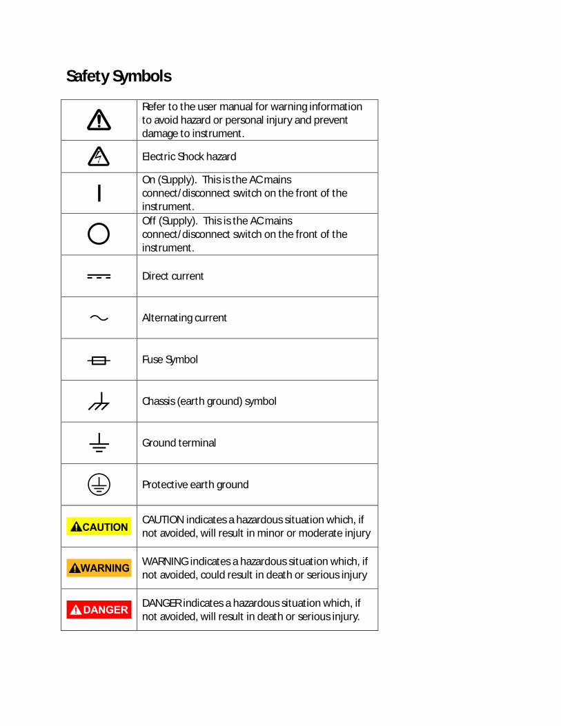
Safety Symbols
Refer to the user manual for warning information to avoid hazard or personal injury and prevent damage to instrument.
Electric Shock hazard
On (Supply). This is the AC mains connect/disconnect switch on the front of the instrument.
Off (Supply). This is the AC mains connect/disconnect switch on the front of the instrument.
Direct current
Alternating current
Fuse Symbol
Chassis (earth ground) symbol
Ground terminal
Protective earth ground
CAUTION indicates a hazardous situation which, if not avoided, will result in minor or moderate injury
WARNING indicates a hazardous situation which, if not avoided, could result in death or serious injury
DANGER indicates a hazardous situation which, if not avoided, will result in death or serious injury.
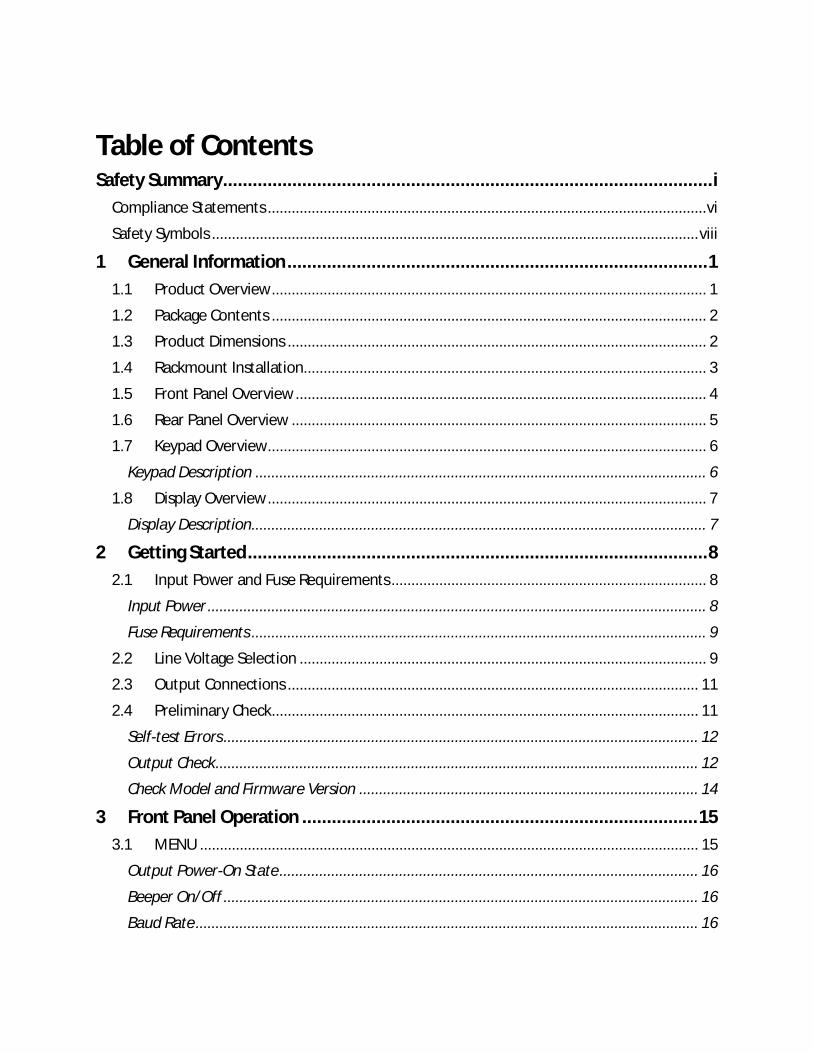
Table of Contents Safety Summary ................................................................................................... i
Compliance Statements .............................................................................................................. vi
Safety Symbols .......................................................................................................................... viii
1 General Information ..................................................................................... 1
1.1 Product Overview ............................................................................................................. 1
1.2 Package Contents ............................................................................................................. 2
1.3 Product Dimensions ......................................................................................................... 2
1.4 Rackmount Installation..................................................................................................... 3
1.5 Front Panel Overview ....................................................................................................... 4
1.6 Rear Panel Overview ........................................................................................................ 5
1.7 Keypad Overview .............................................................................................................. 6
Keypad Description ................................................................................................................. 6
1.8 Display Overview .............................................................................................................. 7
Display Description .................................................................................................................. 7
2 Getting Started ............................................................................................. 8
2.1 Input Power and Fuse Requirements ............................................................................... 8
Input Power ............................................................................................................................. 8
Fuse Requirements .................................................................................................................. 9
2.2 Line Voltage Selection ...................................................................................................... 9
2.3 Output Connections ....................................................................................................... 11
2.4 Preliminary Check ........................................................................................................... 11
Self-test Errors ....................................................................................................................... 12
Output Check ......................................................................................................................... 12
Check Model and Firmware Version ..................................................................................... 14
3 Front Panel Operation ................................................................................ 15
3.1 MENU ............................................................................................................................. 15
Output Power-On State ......................................................................................................... 16
Beeper On/Off ....................................................................................................................... 16
Baud Rate .............................................................................................................................. 16
Memory Group ...................................................................................................................... 17
Combined Series and Parallel Modes .................................................................................... 17
Tracking Mode ...................................................................................................................... 20
3.2 Limit Voltage Protection (LVP) ........................................................................................ 21
3.3 Setting Voltage and Current ........................................................................................... 22
3.4 Save and Recall ............................................................................................................... 22
Select Memory Group ........................................................................................................... 23
Save Settings ......................................................................................................................... 23
Recall Settings ....................................................................................................................... 23
3.5 Key Lock .......................................................................................................................... 24
4 Protections ................................................................................................. 25
Over Temperature Protection ................................................................................................... 25
Over Voltage Protection (OVP).................................................................................................. 25
5 Remote Operation ...................................................................................... 26
Communication cables .............................................................................................................. 26
USB to TTL Adapter IT-E132B ................................................................................................ 26
RS-232 Settings ......................................................................................................................... 27
6 Remote Commands .................................................................................... 28
7 Troubleshooting Guide ............................................................................... 29
General .................................................................................................................................. 29
Remote Control ..................................................................................................................... 29
8 Specifications ............................................................................................. 30
9 Calibration .................................................................................................. 32
SERVICE INFORMATION ..................................................................................... 33
LIMITED THREE-YEAR WARRANTY ..................................................................... 34
1 General Information
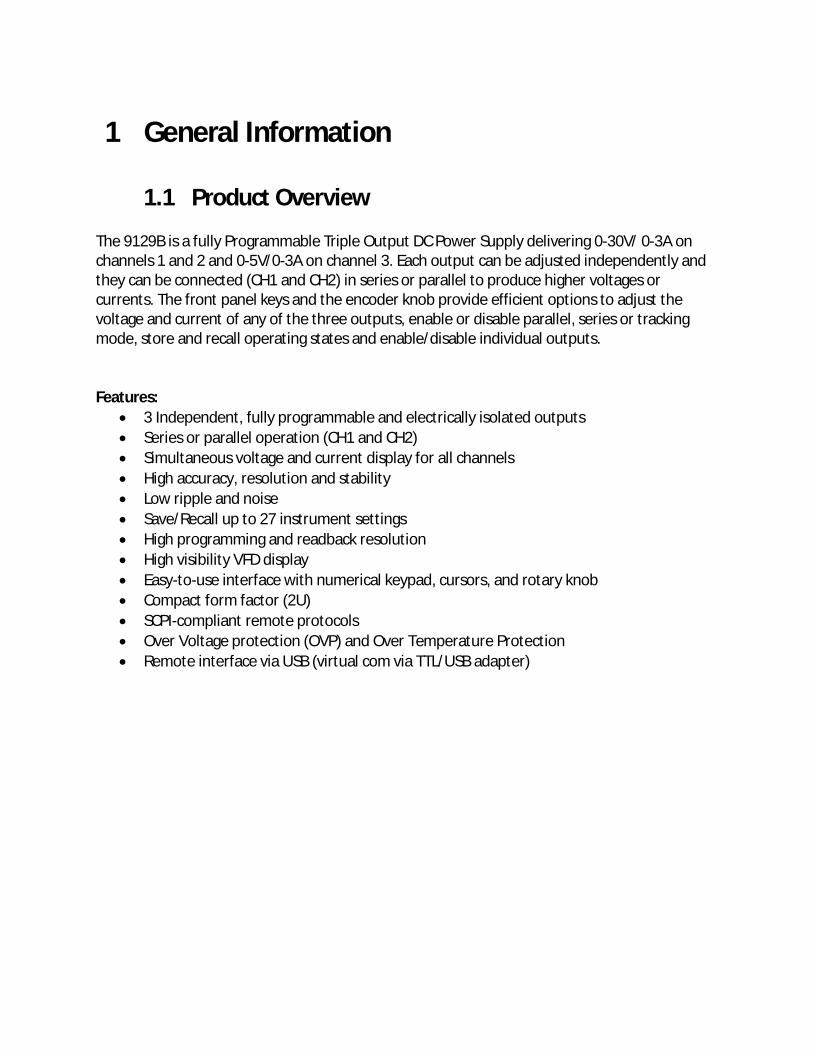
1.1 Product Overview The 9129B is a fully Programmable Triple Output DC Power Supply delivering 0-30V/ 0-3A on channels 1 and 2 and 0-5V/0-3A on channel 3. Each output can be adjusted independently and they can be connected (CH1 and CH2) in series or parallel to produce higher voltages or currents. The front panel keys and the encoder knob provide efficient options to adjust the voltage and current of any of the three outputs, enable or disable parallel, series or tracking mode, store and recall operating states and enable/disable individual outputs. Features:
• 3 Independent, fully programmable and electrically isolated outputs • Series or parallel operation (CH1 and CH2) • Simultaneous voltage and current display for all channels • High accuracy, resolution and stability • Low ripple and noise • Save/Recall up to 27 instrument settings • High programming and readback resolution • High visibility VFD display • Easy-to-use interface with numerical keypad, cursors, and rotary knob • Compact form factor (2U) • SCPI-compliant remote protocols • Over Voltage protection (OVP) and Over Temperature Protection • Remote interface via USB (virtual com via TTL/USB adapter)
1.2 Package Contents
Please inspect the instrument mechanically and electrically upon receiving it. Unpack all items from the shipping carton, and check for any obvious signs of physical damage that may have occurred during transportation. Report any damage to the shipping agent immediately. Save the original packing carton for possible future reshipment. Every power supply is shipped with the following contents:
• 1 x 9129B Power Supply • 1 x AC Power Cord • 1 x Certificate of Calibration • 1 x Test Report • 1 x TTL to USB serial adapter IT-E132B
Verify that all items above are included in the shipping container. If anything is missing, please contact B&K Precision.
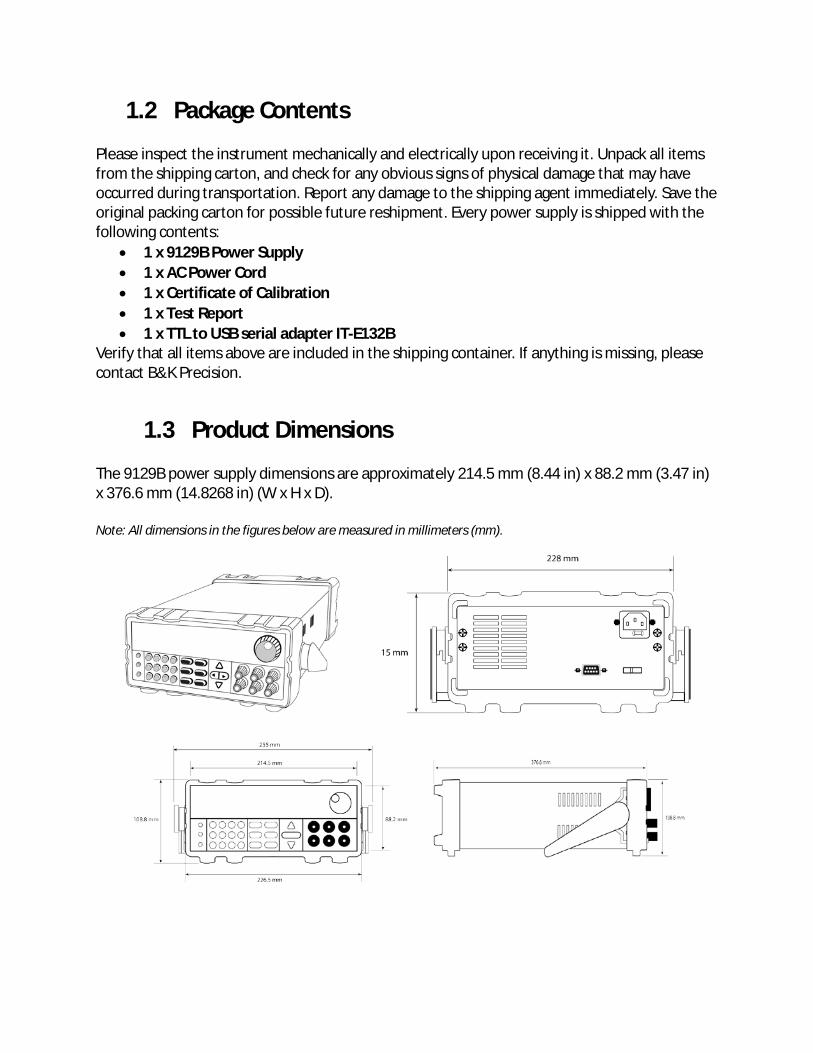
1.3 Product Dimensions The 9129B power supply dimensions are approximately 214.5 mm (8.44 in) x 88.2 mm (3.47 in) x 376.6 mm (14.8268 in) (W x H x D). Note: All dimensions in the figures below are measured in millimeters (mm).
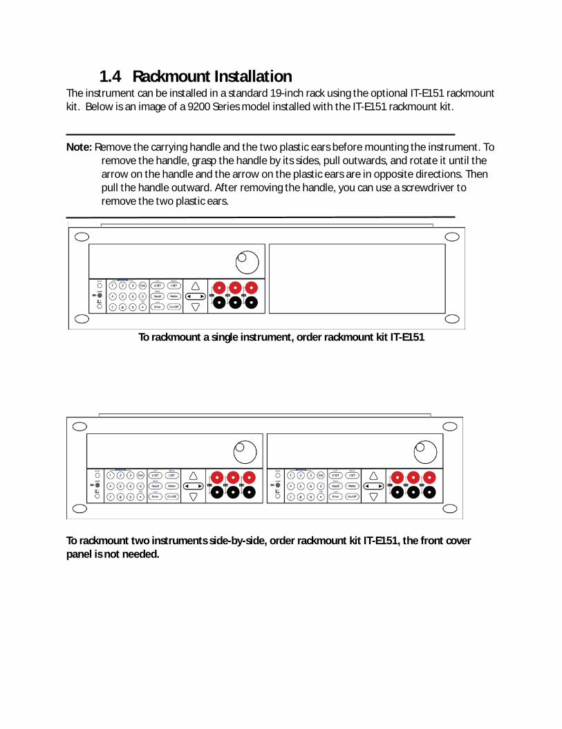
1.4 Rackmount Installation The instrument can be installed in a standard 19-inch rack using the optional IT-E151 rackmount kit. Below is an image of a 9200 Series model installed with the IT-E151 rackmount kit. Note: Remove the carrying handle and the two plastic ears before mounting the instrument. To
remove the handle, grasp the handle by its sides, pull outwards, and rotate it until the arrow on the handle and the arrow on the plastic ears are in opposite directions. Then pull the handle outward. After removing the handle, you can use a screwdriver to remove the two plastic ears.
To rackmount a single instrument, order rackmount kit IT-E151
To rackmount two instruments side-by-side, order rackmount kit IT-E151, the front cover panel is not needed.
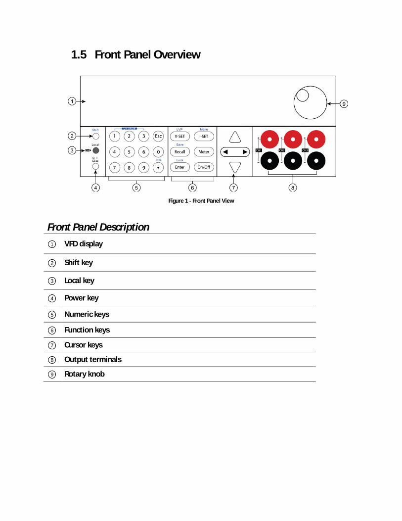
1.5 Front Panel Overview
Figure 1 - Front Panel View
Front Panel Description
VFD display
Shift key
Local key
Power key
Numeric keys
Function keys
Cursor keys
Output terminals
Rotary knob
1
2
3
4
5
6
7
8
9
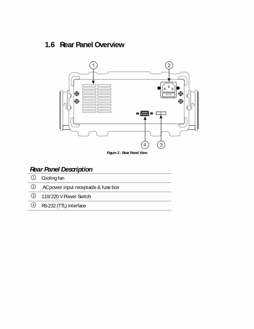
1.6 Rear Panel Overview
Figure 2 - Rear Panel View
Rear Panel Description
Cooling fan
AC power input receptacle & fuse box
110/220 V Power Switch
RS-232 (TTL) interface
1
2
3
4
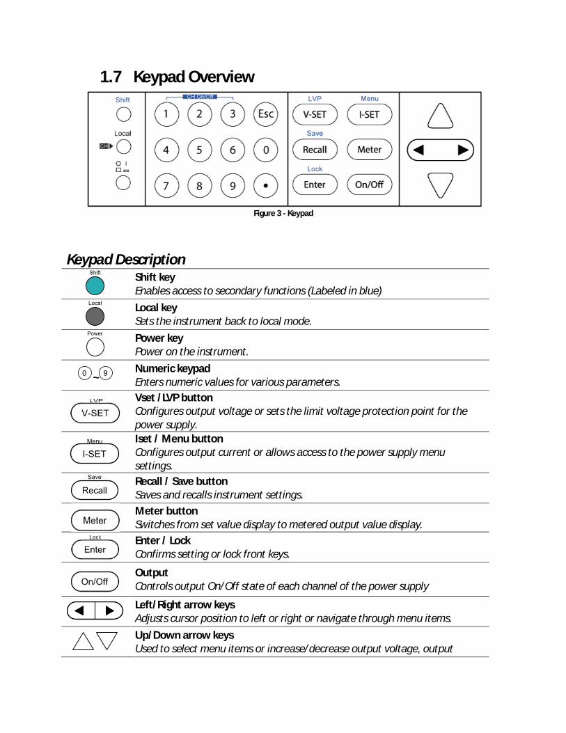
1.7 Keypad Overview
Figure 3 - Keypad
Keypad Description
Shift key Enables access to secondary functions (Labeled in blue)
Local key Sets the instrument back to local mode.
Power key Power on the instrument.
~ Numeric keypad Enters numeric values for various parameters.
Vset /LVP button Configures output voltage or sets the limit voltage protection point for the power supply.
Iset / Menu button Configures output current or allows access to the power supply menu settings.
Recall / Save button Saves and recalls instrument settings.
Meter button Switches from set value display to metered output value display.
Enter / Lock Confirms setting or lock front keys.
Output Controls output On/Off state of each channel of the power supply
Left/Right arrow keys Adjusts cursor position to left or right or navigate through menu items.
Up/Down arrow keys Used to select menu items or increase/decrease output voltage, output
current or navigate through menu items.
Esc key Cancel and return to previous menu.
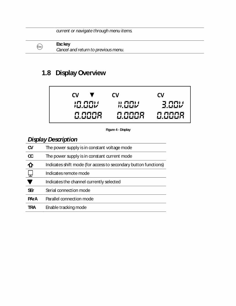
1.8 Display Overview
Figure 4 - Display
Display Description CV The power supply is in constant voltage mode
CC The power supply is in constant current mode
Indicates shift mode (for access to secondary button functions)
Indicates remote mode
Indicates the channel currently selected
SEr Serial connection mode
PArA Parallel connection mode
TRA Enable tracking mode
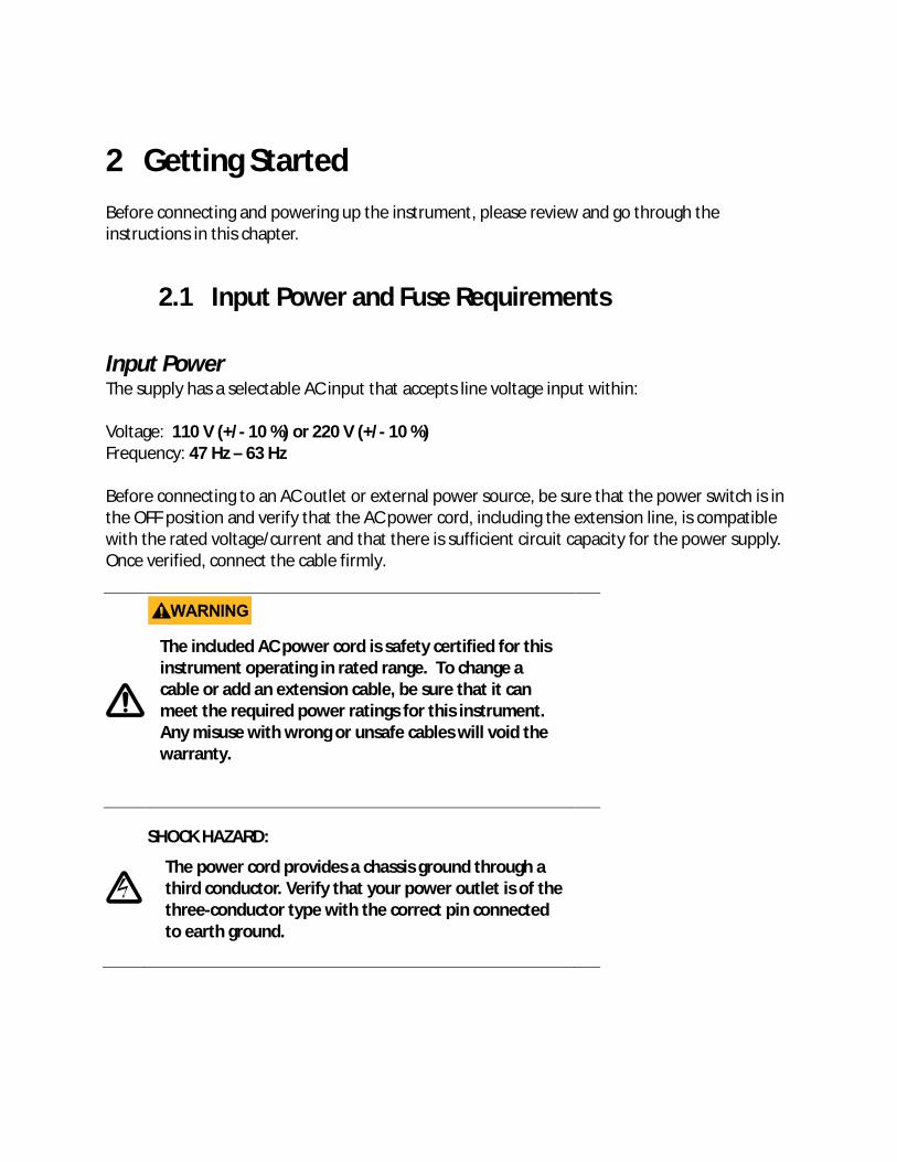
2 Getting Started Before connecting and powering up the instrument, please review and go through the instructions in this chapter.
2.1 Input Power and Fuse Requirements
Input Power The supply has a selectable AC input that accepts line voltage input within: Voltage: 110 V (+/- 10 %) or 220 V (+/- 10 %) Frequency: 47 Hz – 63 Hz Before connecting to an AC outlet or external power source, be sure that the power switch is in the OFF position and verify that the AC power cord, including the extension line, is compatible with the rated voltage/current and that there is sufficient circuit capacity for the power supply. Once verified, connect the cable firmly.
The included AC power cord is safety certified for this instrument operating in rated range. To change a cable or add an extension cable, be sure that it can meet the required power ratings for this instrument. Any misuse with wrong or unsafe cables will void the warranty.
SHOCK HAZARD:
The power cord provides a chassis ground through a third conductor. Verify that your power outlet is of the three-conductor type with the correct pin connected to earth ground.
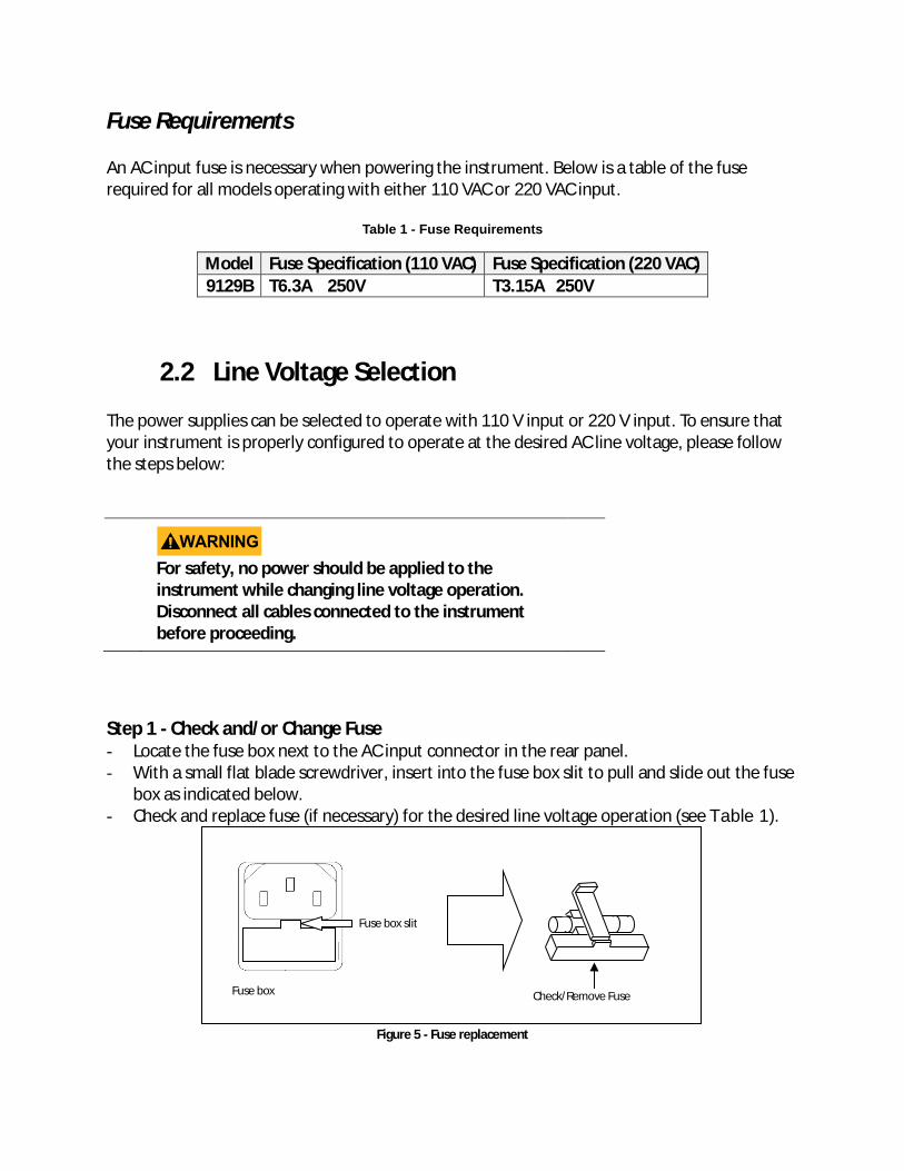
Fuse Requirements An AC input fuse is necessary when powering the instrument. Below is a table of the fuse required for all models operating with either 110 VAC or 220 VAC input.
Table 1 - Fuse Requirements
Model Fuse Specification (110 VAC) Fuse Specification (220 VAC) 9129B T6.3A 250V T3.15A 250V
2.2 Line Voltage Selection The power supplies can be selected to operate with 110 V input or 220 V input. To ensure that your instrument is properly configured to operate at the desired AC line voltage, please follow the steps below:
For safety, no power should be applied to the instrument while changing line voltage operation. Disconnect all cables connected to the instrument before proceeding.
Step 1 - Check and/or Change Fuse - Locate the fuse box next to the AC input connector in the rear panel. - With a small flat blade screwdriver, insert into the fuse box slit to pull and slide out the fuse
box as indicated below. - Check and replace fuse (if necessary) for the desired line voltage operation (see Table 1).
Figure 5 - Fuse replacement
Fuse box slit
Fuse box Check/Remove Fuse
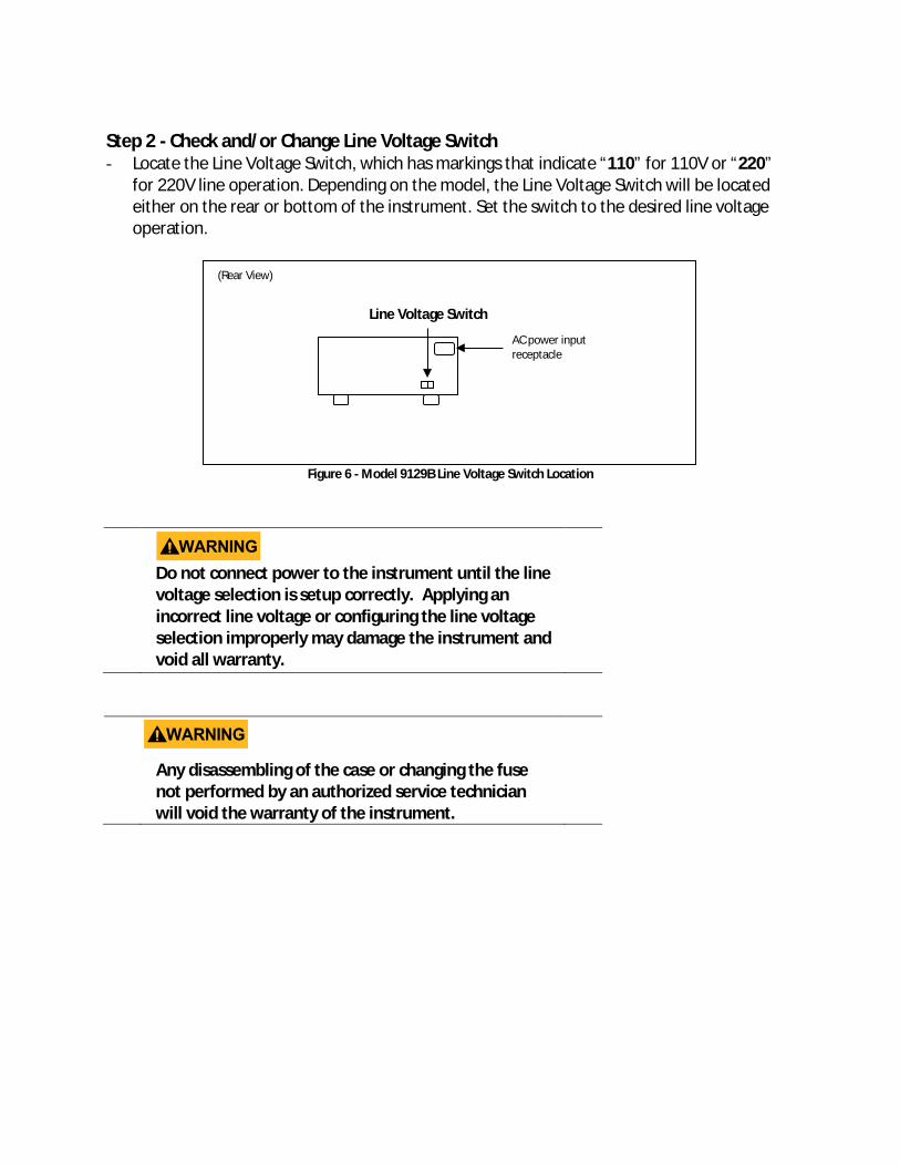
Step 2 - Check and/or Change Line Voltage Switch - Locate the Line Voltage Switch, which has markings that indicate “110” for 110V or “220”
for 220V line operation. Depending on the model, the Line Voltage Switch will be located either on the rear or bottom of the instrument. Set the switch to the desired line voltage operation.
Figure 6 - Model 9129B Line Voltage Switch Location
Do not connect power to the instrument until the line voltage selection is setup correctly. Applying an incorrect line voltage or configuring the line voltage selection improperly may damage the instrument and void all warranty.
Any disassembling of the case or changing the fuse not performed by an authorized service technician will void the warranty of the instrument.
Line Voltage Switch
AC power input receptacle
(Rear View)
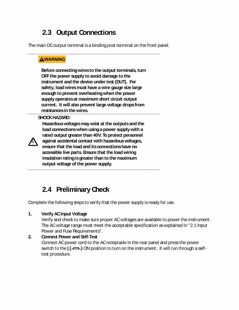
2.3 Output Connections The main DC output terminal is a binding post terminal on the front panel.
Before connecting wires to the output terminals, turn OFF the power supply to avoid damage to the instrument and the device under test (DUT). For safety, load wires must have a wire gauge size large enough to prevent overheating when the power supply operates at maximum short circuit output current. It will also prevent large voltage drops from resistances in the wires.
SHOCK HAZARD: Hazardous voltages may exist at the outputs and the load connections when using a power supply with a rated output greater than 40V. To protect personnel against accidental contact with hazardous voltages, ensure that the load and its connections have no accessible live parts. Ensure that the load wiring insulation rating is greater than to the maximum output voltage of the power supply.
2.4 Preliminary Check Complete the following steps to verify that the power supply is ready for use. 1. Verify AC Input Voltage
Verify and check to make sure proper AC voltages are available to power the instrument. The AC voltage range must meet the acceptable specification as explained in “2.1 Input Power and Fuse Requirements”.
2. Connect Power and Self-Test Connect AC power cord to the AC receptacle in the rear panel and press the power switch to the |( ) ON position to turn on the instrument. It will run through a self-test procedure.
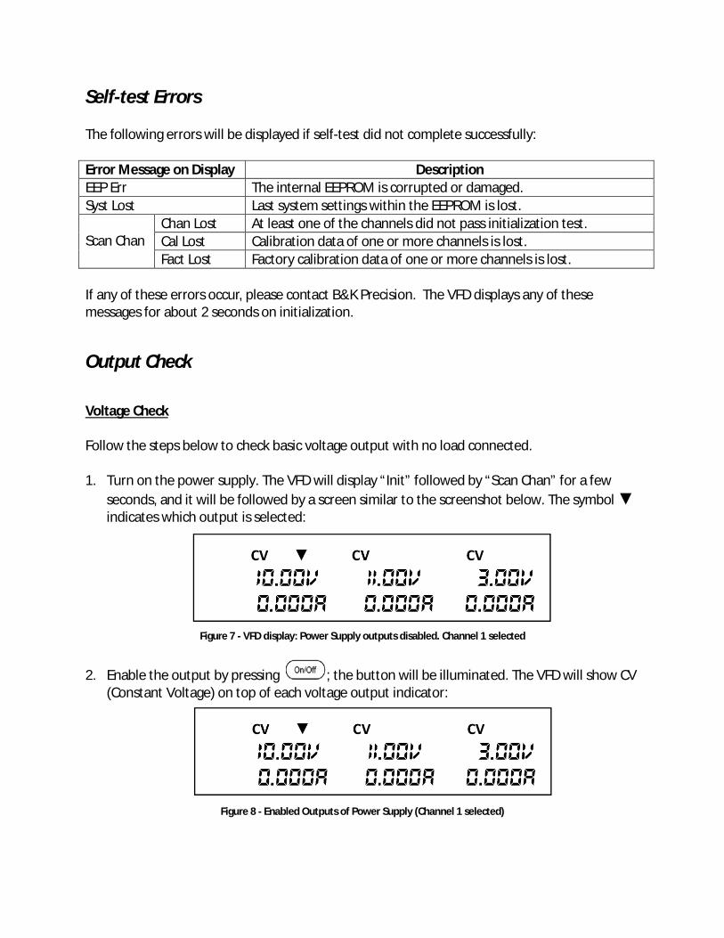
Self-test Errors The following errors will be displayed if self-test did not complete successfully: Error Message on Display Description EEP Err The internal EEPROM is corrupted or damaged. Syst Lost Last system settings within the EEPROM is lost. Scan Chan
Chan Lost At least one of the channels did not pass initialization test. Cal Lost Calibration data of one or more channels is lost. Fact Lost Factory calibration data of one or more channels is lost.
If any of these errors occur, please contact B&K Precision. The VFD displays any of these messages for about 2 seconds on initialization.
Output Check
Voltage Check Follow the steps below to check basic voltage output with no load connected. 1. Turn on the power supply. The VFD will display “Init” followed by “Scan Chan” for a few
seconds, and it will be followed by a screen similar to the screenshot below. The symbol ▼ indicates which output is selected:
Figure 7 - VFD display: Power Supply outputs disabled. Channel 1 selected
2. Enable the output by pressing ; the button will be illuminated. The VFD will show CV (Constant Voltage) on top of each voltage output indicator:
Figure 8 - Enabled Outputs of Power Supply (Channel 1 selected)
3. Using the numeric keypad or the voltage adjust rotary knob, enter a voltage value. The
voltage display will now show the value you entered. If entering with numeric keypad,
press the button first, then enter the value and press the button.
4. If the button is not already illuminated, press it once to display the measured voltage at the output. The voltage may fluctuate slightly from the value entered in the previous step.
5. (Optional) You may also verify the output voltage by connecting the (+) and (-) terminals to an external voltmeter. The measured value should match or be comparable to the entered voltage value.
6. Check the other two channels following the same procedure.
Current Check Follow the steps below to check current output of the power supply.
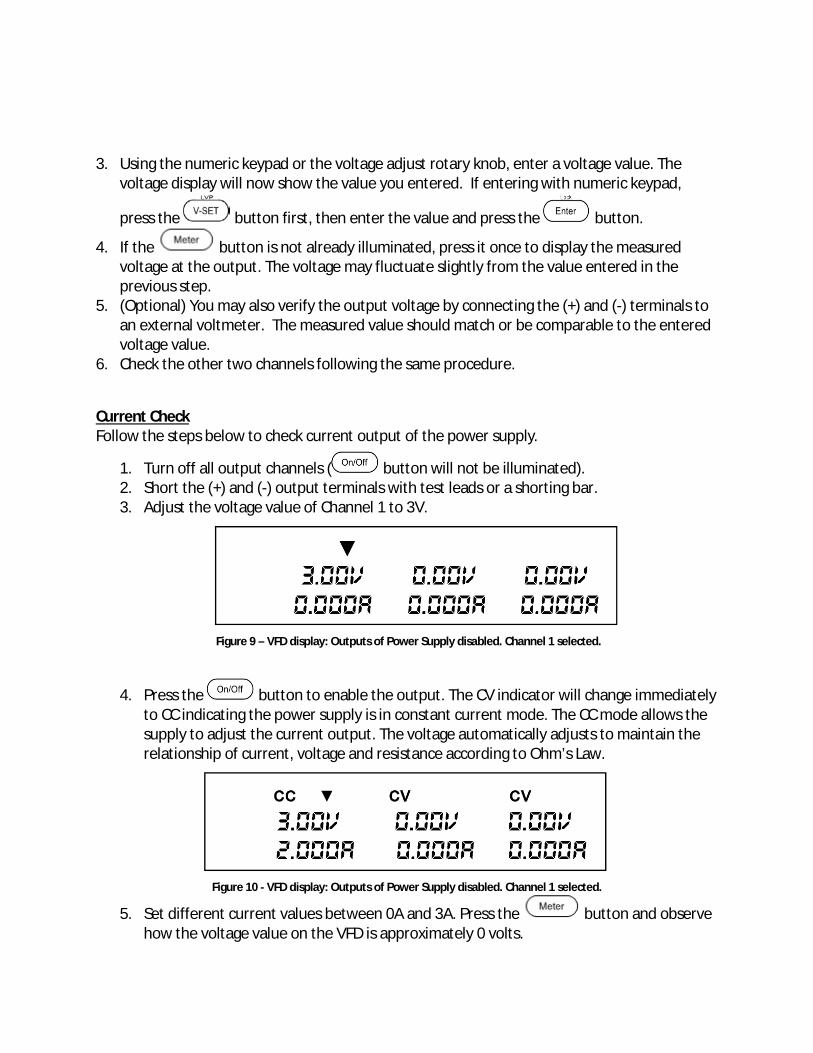
1. Turn off all output channels ( button will not be illuminated). 2. Short the (+) and (-) output terminals with test leads or a shorting bar. 3. Adjust the voltage value of Channel 1 to 3V.
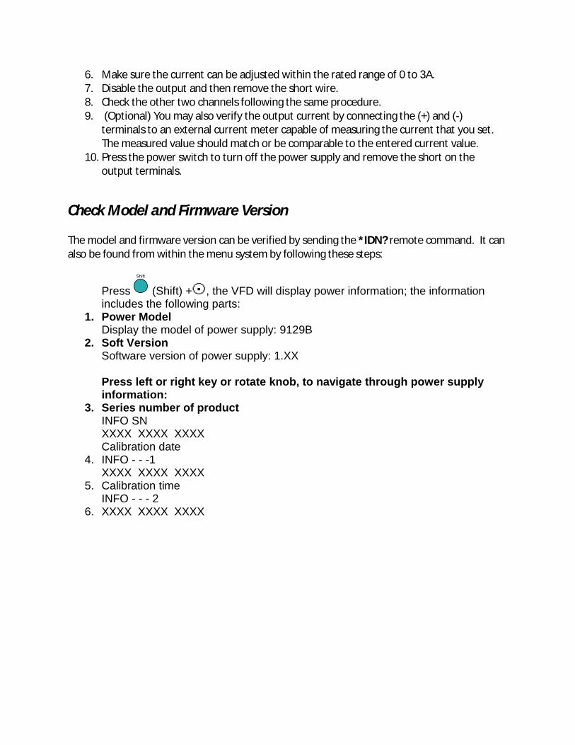
4. Press the button to enable the output. The CV indicator will change immediately to CC indicating the power supply is in constant current mode. The CC mode allows the supply to adjust the current output. The voltage automatically adjusts to maintain the relationship of current, voltage and resistance according to Ohm’s Law.
Figure 10 - VFD display: Outputs of Power Supply disabled. Channel 1 selected.
5. Set different current values between 0A and 3A. Press the button and observe how the voltage value on the VFD is approximately 0 volts.
Figure 9 – VFD display: Outputs of Power Supply disabled. Channel 1 selected.
6. Make sure the current can be adjusted within the rated range of 0 to 3A. 7. Disable the output and then remove the short wire. 8. Check the other two channels following the same procedure. 9. (Optional) You may also verify the output current by connecting the (+) and (-)
terminals to an external current meter capable of measuring the current that you set. The measured value should match or be comparable to the entered current value.
10. Press the power switch to turn off the power supply and remove the short on the output terminals.
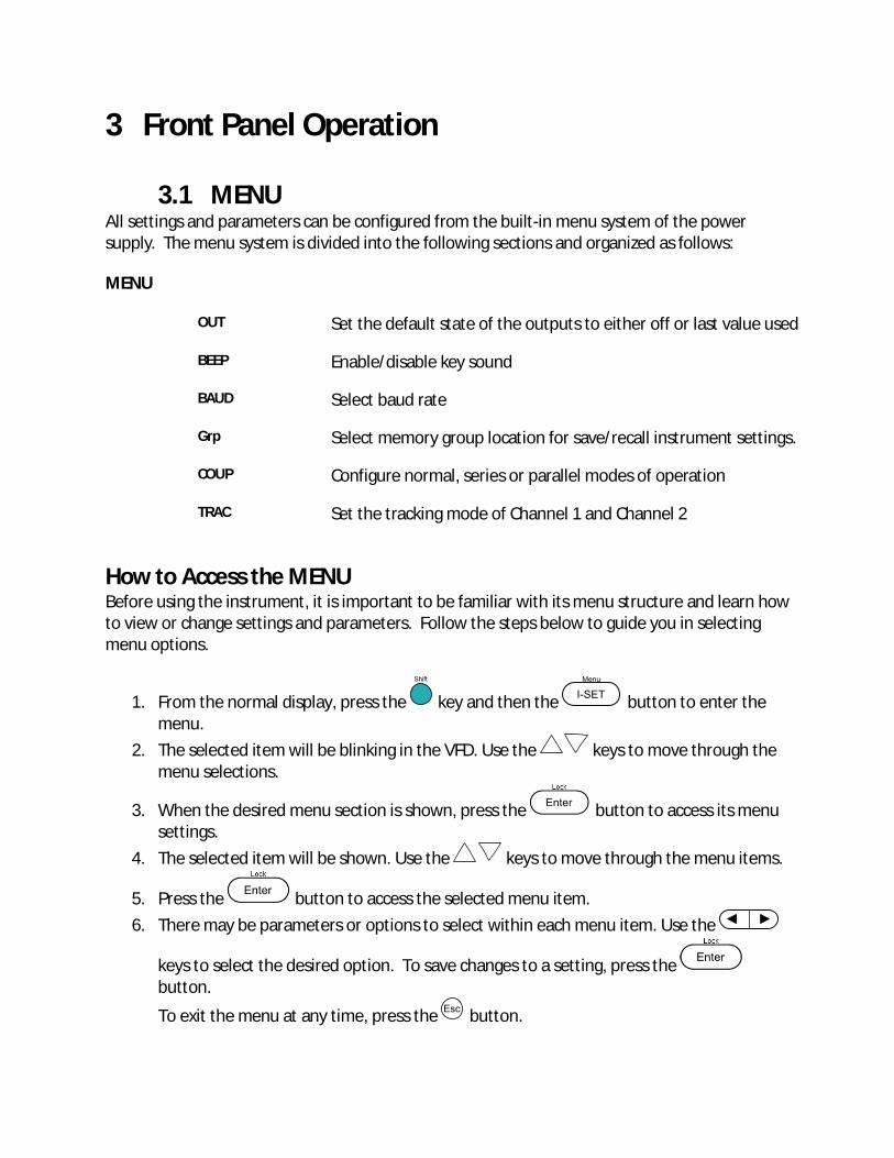
Check Model and Firmware Version The model and firmware version can be verified by sending the *IDN? remote command. It can also be found from within the menu system by following these steps:
Press (Shift) + , the VFD will display power information; the information includes the following parts:
1. Power Model Display the model of power supply: 9129B
2. Soft Version Software version of power supply: 1.XX Press left or right key or rotate knob, to navigate through power supply information:
3. Series number of product INFO SN XXXX XXXX XXXX Calibration date
4. INFO - - -1 XXXX XXXX XXXX
5. Calibration time INFO - - - 2
6. XXXX XXXX XXXX
3 Front Panel Operation
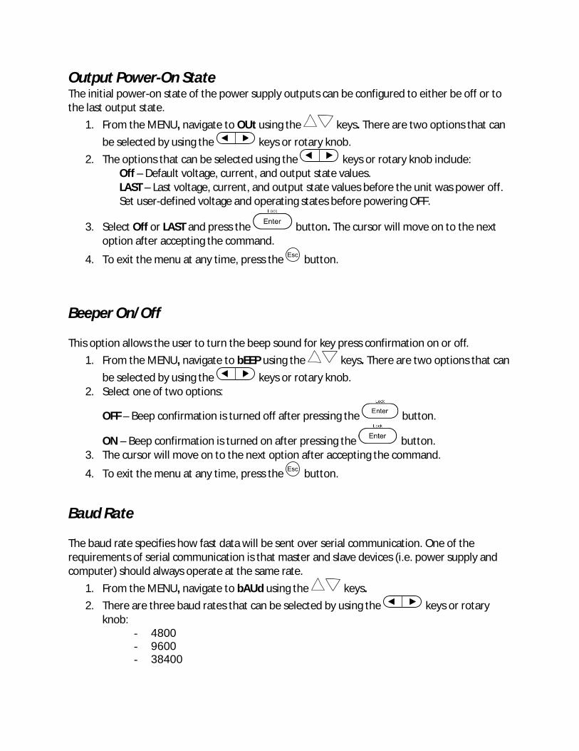
3.1 MENU All settings and parameters can be configured from the built-in menu system of the power supply. The menu system is divided into the following sections and organized as follows: MENU
OUT Set the default state of the outputs to either off or last value used
BEEP Enable/disable key sound
BAUD Select baud rate
Grp Select memory group location for save/recall instrument settings.
COUP Configure normal, series or parallel modes of operation
TRAC Set the tracking mode of Channel 1 and Channel 2
How to Access the MENU Before using the instrument, it is important to be familiar with its menu structure and learn how to view or change settings and parameters. Follow the steps below to guide you in selecting menu options.
1. From the normal display, press the key and then the button to enter the menu.
2. The selected item will be blinking in the VFD. Use the keys to move through the menu selections.
3. When the desired menu section is shown, press the button to access its menu settings.
4. The selected item will be shown. Use the keys to move through the menu items.
5. Press the button to access the selected menu item. 6. There may be parameters or options to select within each menu item. Use the
keys to select the desired option. To save changes to a setting, press the button.
To exit the menu at any time, press the button.
Output Power-On State The initial power-on state of the power supply outputs can be configured to either be off or to the last output state.
1. From the MENU, navigate to OUt using the keys. There are two options that can be selected by using the keys or rotary knob.
2. The options that can be selected using the keys or rotary knob include: Off – Default voltage, current, and output state values. LAST – Last voltage, current, and output state values before the unit was power off. Set user-defined voltage and operating states before powering OFF.
3. Select Off or LAST and press the button. The cursor will move on to the next option after accepting the command.
4. To exit the menu at any time, press the button.
Beeper On/Off This option allows the user to turn the beep sound for key press confirmation on or off.
1. From the MENU, navigate to bEEP using the keys. There are two options that can be selected by using the keys or rotary knob.
2. Select one of two options:
OFF – Beep confirmation is turned off after pressing the button.
ON – Beep confirmation is turned on after pressing the button. 3. The cursor will move on to the next option after accepting the command.
4. To exit the menu at any time, press the button.
Baud Rate The baud rate specifies how fast data will be sent over serial communication. One of the requirements of serial communication is that master and slave devices (i.e. power supply and computer) should always operate at the same rate.
1. From the MENU, navigate to bAUd using the keys. 2. There are three baud rates that can be selected by using the keys or rotary
knob: - 4800 - 9600 - 38400

Select one rate and press the button to select desired baud rate. 3. The cursor will move on to the next option after accepting the command.
4. To exit the menu at any time, press the button.
Note: All serial settings must match the settings configured on the PC in order for communication to link successfully.
Memory Group The instrument can save up to 27 system configurations for quick access. The non-volatile memory location is divided into three groups: Grp1, Grp2 and Grp3. Each group is divided into 9 locations.
1. From the main menu, navigate to the group memory option (Grp) using the keys. There are three options that can be selected by using the keys or rotary knob:
- Grp1 - Grp2 - Grp3
Each group has 9 locations, therefore, allowing the customer to save 27 output state configurations.
2. Select one of the three memory location groups and then press the button. The cursor will move on to the next option after accepting the command.
3. To exit the menu at any time, press the button.
Note: Any settings saved or recalled following the procedures in this section will be stored or recalled from the memory group selected in the Grp Menu.
Combined Series and Parallel Modes This section will describe the three different types of output configuration modes for the power supply. Off (normal operation), series or parallel configurations are available. Normal Mode (OFF)
This option is used to turn off/remove series or parallel configuration and returns the unit to normal output.
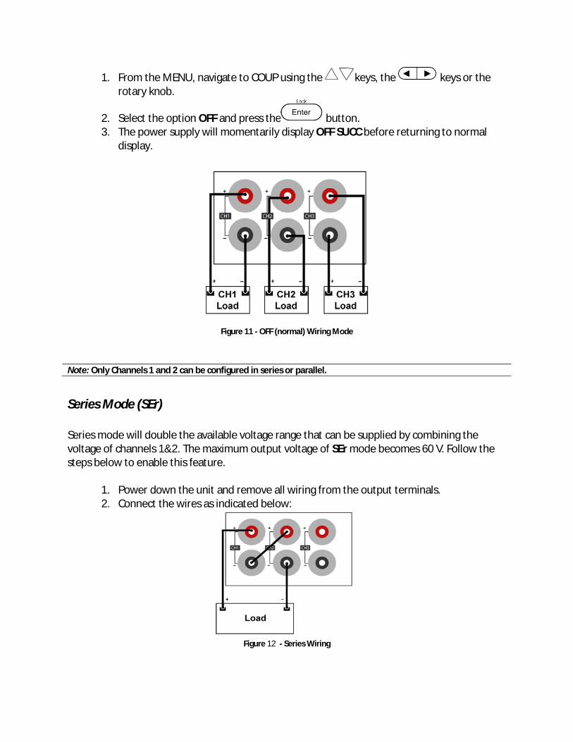
1. From the MENU, navigate to COUP using the keys, the keys or the rotary knob.
2. Select the option OFF and press the button. 3. The power supply will momentarily display OFF SUCC before returning to normal
display.
Figure 11 - OFF (normal) Wiring Mode
Series Mode (SEr) Series mode will double the available voltage range that can be supplied by combining the voltage of channels 1&2. The maximum output voltage of SEr mode becomes 60 V. Follow the steps below to enable this feature.
1. Power down the unit and remove all wiring from the output terminals. 2. Connect the wires as indicated below:
Figure 12 - Series Wiring
Note: Only Channels 1 and 2 can be configured in series or parallel.
3. Power on the unit and verify that the outputs are turned off. The button should not be illuminated.
4. From the MENU, navigate to COUP using the keys, keys or the rotary knob.
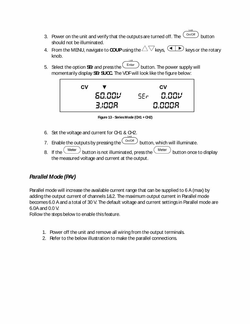
5. Select the option SEr and press the button. The power supply will momentarily display SEr SUCC. The VDF will look like the figure below:
Figure 13 - Series Mode (CH1 + CH2)
6. Set the voltage and current for CH1 & CH2.
7. Enable the outputs by pressing the button, which will illuminate.
8. If the button is not illuminated, press the button once to display the measured voltage and current at the output.
Parallel Mode (PAr) Parallel mode will increase the available current range that can be supplied to 6 A (max) by adding the output current of channels 1&2. The maximum output current in Parallel mode becomes 6.0 A and a total of 30 V. The default voltage and current settings in Parallel mode are 6.0A and 0.0 V. Follow the steps below to enable this feature.
1. Power off the unit and remove all wiring from the output terminals. 2. Refer to the below illustration to make the parallel connections.
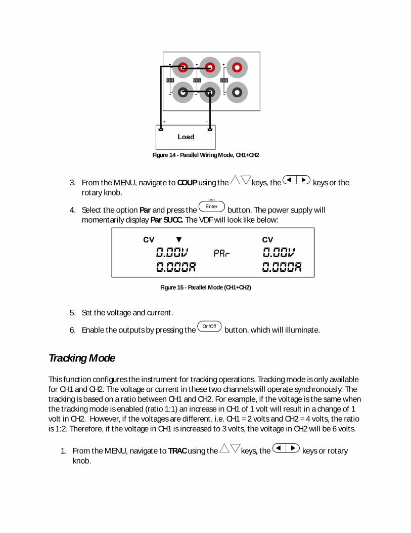
Figure 14 - Parallel Wiring Mode, CH1+CH2
3. From the MENU, navigate to COUP using the keys, the keys or the
rotary knob.
4. Select the option Par and press the button. The power supply will momentarily display Par SUCC. The VDF will look like below:
Figure 15 - Parallel Mode (CH1+CH2)
5. Set the voltage and current.
6. Enable the outputs by pressing the button, which will illuminate.
Tracking Mode This function configures the instrument for tracking operations. Tracking mode is only available for CH1 and CH2. The voltage or current in these two channels will operate synchronously. The tracking is based on a ratio between CH1 and CH2. For example, if the voltage is the same when the tracking mode is enabled (ratio 1:1) an increase in CH1 of 1 volt will result in a change of 1 volt in CH2. However, if the voltages are different, i.e. CH1 = 2 volts and CH2 = 4 volts, the ratio is 1:2. Therefore, if the voltage in CH1 is increased to 3 volts, the voltage in CH2 will be 6 volts.
1. From the MENU, navigate to TRAC using the keys, the keys or rotary knob.

2. Select one of the options available, OFF or ON and press the button to save changes. The VFD will momentarily show “Trac Succ” to show that Track Mode is enabled.
3. The output of CH1 and CH2 can be adjusted simultaneously as explained above.
To check if the unit is in TRACK MODE, press the button and the display will show the indicator “trA” underneath the measured voltage for each channel when the output is off. Note: Set the ratio before enabling tracking. The tracking is based on the ratio between CH1 and CH2 when the tracking mode is active.
3.2 Limit Voltage Protection (LVP) The 9129B Model power supply provides a Limit Voltage Protection function to protect the power supply when the voltage at the output terminal exceeds the LVP voltage setting or to prevent accidental changes to the output settings that exceeds the DUT (device under test) limit. Follow the steps below to set the LVP limit.
1. Press the key to select channel.
2. Press the key and then press the button to enter the LVP menu of the channel selected.
The button and the voltage channel selected (in the VFD) will blink until a value
is entered and the button is pressed.
3. Enter a voltage using the numeric keypad, rotary knob or the keys. Use one of the steps below.
Using the keypad: Enter the voltage on the keypad followed by the button. Using the rotary knob: Press the keys to move the cursor position and
adjust the voltage value using the rotary knob followed by the button. Using the Up/Down arrows: Press the keys to move the cursor position
and adjust the voltage value using the keys followed by the button.
4. Repeat the above steps for setting each channel.
Note: Avoid exceeding 120% of the rated voltage across the output terminals or the
power supply may be damaged.
Note: When a specific voltage cannot be set, check the LVP voltage setting to ensure the desired voltage is less than or equal to the LVP value.
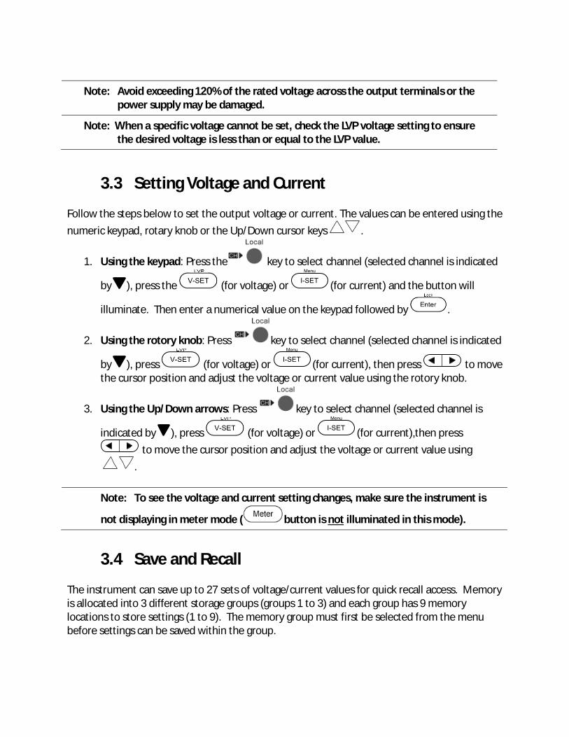
3.3 Setting Voltage and Current Follow the steps below to set the output voltage or current. The values can be entered using the numeric keypad, rotary knob or the Up/Down cursor keys .
1. Using the keypad: Press the key to select channel (selected channel is indicated
by ), press the (for voltage) or (for current) and the button will
illuminate. Then enter a numerical value on the keypad followed by .
2. Using the rotory knob: Press key to select channel (selected channel is indicated
by ), press (for voltage) or (for current), then press to move the cursor position and adjust the voltage or current value using the rotory knob.
3. Using the Up/Down arrows: Press key to select channel (selected channel is
indicated by ), press (for voltage) or (for current),then press to move the cursor position and adjust the voltage or current value using
.
Note: To see the voltage and current setting changes, make sure the instrument is
not displaying in meter mode ( button is not illuminated in this mode).
3.4 Save and Recall The instrument can save up to 27 sets of voltage/current values for quick recall access. Memory is allocated into 3 different storage groups (groups 1 to 3) and each group has 9 memory locations to store settings (1 to 9). The memory group must first be selected from the menu before settings can be saved within the group.
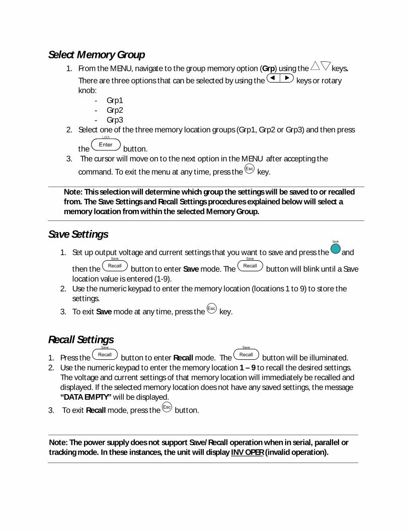
Select Memory Group 1. From the MENU, navigate to the group memory option (Grp) using the keys.
There are three options that can be selected by using the keys or rotary knob:
- Grp1 - Grp2 - Grp3
2. Select one of the three memory location groups (Grp1, Grp2 or Grp3) and then press
the button. 3. The cursor will move on to the next option in the MENU after accepting the
command. To exit the menu at any time, press the key.
Note: This selection will determine which group the settings will be saved to or recalled from. The Save Settings and Recall Settings procedures explained below will select a memory location from within the selected Memory Group.
Save Settings
1. Set up output voltage and current settings that you want to save and press the and
then the button to enter Save mode. The button will blink until a Save location value is entered (1-9).
2. Use the numeric keypad to enter the memory location (locations 1 to 9) to store the settings.
3. To exit Save mode at any time, press the key.
Recall Settings
1. Press the button to enter Recall mode. The button will be illuminated. 2. Use the numeric keypad to enter the memory location 1 – 9 to recall the desired settings.
The voltage and current settings of that memory location will immediately be recalled and displayed. If the selected memory location does not have any saved settings, the message “DATA EMPTY” will be displayed.
3. To exit Recall mode, press the button.
Note: The power supply does not support Save/Recall operation when in serial, parallel or tracking mode. In these instances, the unit will display INV OPER (invalid operation).
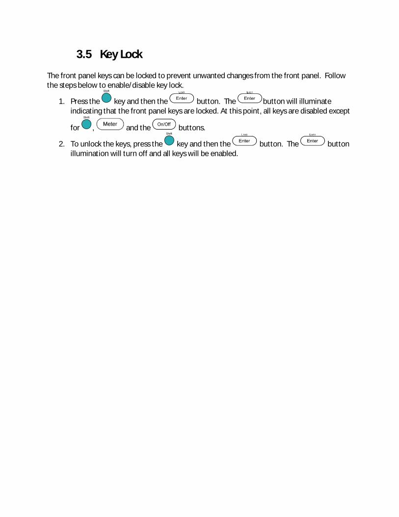
3.5 Key Lock The front panel keys can be locked to prevent unwanted changes from the front panel. Follow the steps below to enable/disable key lock.
1. Press the key and then the button. The button will illuminate indicating that the front panel keys are locked. At this point, all keys are disabled except
for , and the buttons.
2. To unlock the keys, press the key and then the button. The button illumination will turn off and all keys will be enabled.
4 Protections
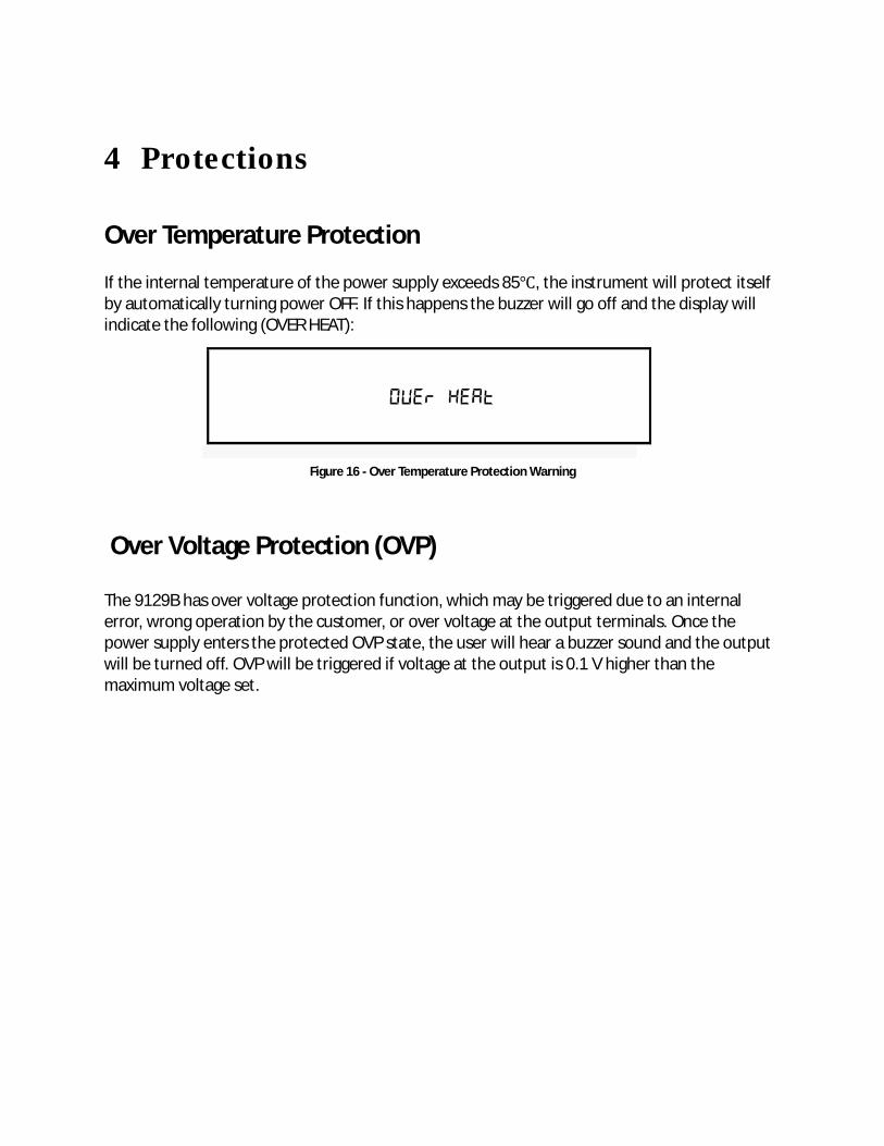
Over Temperature Protection If the internal temperature of the power supply exceeds 85℃, the instrument will protect itself by automatically turning power OFF. If this happens the buzzer will go off and the display will indicate the following (OVER HEAT):
Figure 16 - Over Temperature Protection Warning
Over Voltage Protection (OVP) The 9129B has over voltage protection function, which may be triggered due to an internal error, wrong operation by the customer, or over voltage at the output terminals. Once the power supply enters the protected OVP state, the user will hear a buzzer sound and the output will be turned off. OVP will be triggered if voltage at the output is 0.1 V higher than the maximum voltage set.
5 Remote Operation Users can program the power supply by using the SCPI (Standard Commands for Programmable Instruments) commands over the TTL remote interface (via USB virtual com with IT-E132B).
Communication cables The power supply has a DB9 connector on the rear panel that allows remote communication via the IT-E132B adapter.
Do not connect the DB9 connector to a standard RS-232 serial port. Doing so may damage the instrument. The instrument outputs TTL signal levels only, and must be used with IT-E132B adapter to connect to a USB port (virtual com) on a PC.
USB to TTL Adapter IT-E132B Use the IT-E132B USB to TTL adapter to connect a PC to the instrument for remote communication. Connect the INSTRUMENT side of the adapter to the DC load DB9 connector. Connect the COMPUTER end to a USB port on your computer. When connected, the computer will automatically install the appropriate drivers (For Windows® 7 or above). The driver is also available for download at www.bkprecision.com . Upon successful installation of the driver, the USB connection will be registered as a virtual COM device. It can be accessed and control via the assigned COM port (This can be verified in “Device Manager”) the same way as you would with RS-232 serial interfaces.
Note: The RMT indicator will appear on display when the power supply is successfully connected to a PC remotely through any remote interface. Keys on the front panel will be locked until the instrument is in LOCAL mode. To return to LOCAL mode from the front
panel, press the key. The RMT indicator will disappear when the instrument is in LOCAL mode.
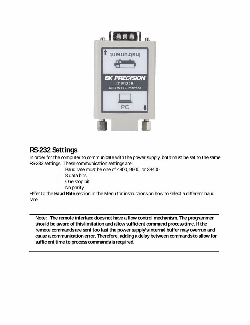
RS-232 Settings In order for the computer to communicate with the power supply, both must be set to the same RS-232 settings. These communication settings are:
- Baud rate must be one of 4800, 9600, or 38400 - 8 data bits - One stop bit - No parity
Refer to the Baud Rate section in the Menu for instructions on how to select a different baud rate.
Note: The remote interface does not have a flow control mechanism. The programmer should be aware of this limitation and allow sufficient command process time. If the remote commands are sent too fast the power supply’s internal buffer may overrun and cause a communication error. Therefore, adding a delay between commands to allow for sufficient time to process commands is required.

6 Remote Commands The instrument supports SCPI commands and some instrument specific commands. These commands enable a computer to remotely communicate and control the instrument over serial using the TTL to USB serial adapter IT-E132B. Refer to the programming manual for details, which can be downloaded from www.bkprecision.com.
7 Troubleshooting Guide Below there are some frequently asked questions and answers. Please check if any apply to your power supply before contacting B&K Precision.
General Q: I cannot power up the power supply. - Check that the power cord is securely connected to the AC input and there is live power
from your electrical AC outlet. - Verify that the AC power coming from the mains contains the correct voltage. The power
supply can accept a specific range of AC input voltages. Refer to section 2.1. Q: How do I set up the supply to run in constant current mode? - The supply is a CV/CC power supply that automatically crosses over from CV to CC upon a
load which draws current at the current limit (I-SET). Therefore, it is dependent on the load. For example, if I-SET is configured as 1 A, the load must draw 1 A before the supply will go into CC mode.
Q: Why is my display voltage lower than the voltage I set? - This is often because of the resistances from the test leads/wires connected between the
supply and the DUT (device under test), which causes a drop in voltage. To minimize this drop, use remote sense terminals to compensate and output a more accurate voltage to the DUT.
Q: I cannot set voltage at the maximum rating. - This may be that the set voltage is outside of the voltage maximum limit. Refer to Limit
Voltage Protection (LVP) section to verify and configure the limits.
Remote Control Q: I am trying to send the commands over RS232 using the TTL to USB serial adapter IT-E132B, but the power supply does not seem to respond. - Check that you are sending ASCII strings that are terminated with a CR (carriage return)
and LF (linefeed) character. - For RS-232, check that the baud rate, parity, data bits, stop bit, and flow control settings
match with the settings configured on the software interface.

8 Specifications Note: All specifications apply to the unit after a temperature stabilization time of 15 minutes over an ambient temperature range of 23 °C ± 5 °C. Specifications are subject to change without notice. Environmental Conditions: This power supply is designed for indoor use and operated with maximum relative humidity of 80%. Model 9129B
Output Rating
Voltage 0-30 V (CH1 & CH2) 0-5 V (CH3)
Current
0-3 A All Channels
Power Line Regulation Voltage ≤ 0.02%+4 mV
Current ≤ 0.2%+3 mA
Load Regulation Voltage ≤ 0.02%+4 mV
Current ≤ 0.20%+3 mA
Ripple and Noise Voltage ≤ 5 mVp-p/1 mVrms
Current ≤ 6 mArms Programming Resolution Voltage 10 mv Current 1 mA Readback Resolution Voltage 10 mV Current 1 mA
Programming Accuracy ± (%output+offset) Voltage ≤ 0.06% + 20 mV Current ≤0.2% + 10 mA Readback Accuracy ± (%output+offset) Voltage ≤ 0.06% + 20 mV
Current ≤0.2% + 10 mA
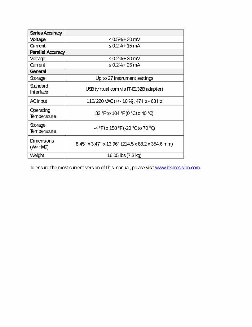
Series Accuracy Voltage ≤ 0.5% + 30 mV Current ≤ 0.2% + 15 mA Parallel Accuracy Voltage ≤ 0.2% + 30 mV Current ≤ 0.2% + 25 mA General Storage Up to 27 instrument settings
Standard Interface USB (virtual com via IT-E132B adapter)
AC Input 110/220 VAC (+/- 10 %), 47 Hz - 63 Hz
Operating Temperature 32 °F to 104 °F (0 °C to 40 °C)
Storage Temperature -4 °F to 158 °F (-20 °C to 70 °C)
Dimensions (W×H×D) 8.45” x 3.47” x 13.96” (214.5 x 88.2 x 354.6 mm)
Weight 16.05 lbs (7.3 kg) To ensure the most current version of this manual, please visit www.bkprecision.com.

9 Calibration We recommend a calibration interval of once per year to ensure that the power supply meets specifications.

SERVICE INFORMATION
Warranty Service: Please go to the support and service section on our website at www.bkprecision.com to obtain a RMA #. Return the product in the original packaging with proof of purchase to the address below. Clearly state on the RMA the performance problem and return any leads, probes, connectors and accessories that you are using with the device. Non-Warranty Service: Please go to the support and service section on our website at www.bkprecision.com to obtain a RMA #. Return the product in the original packaging to the address below. Clearly state on the RMA the performance problem and return any leads, probes, connectors and accessories that you are using with the device. Customers not on an open account must include payment in the form of a money order or credit card. For the most current repair charges please refer to the service and support section on our website.
Return all merchandise to B&K Precision Corp. with prepaid shipping. The flat-rate repair charge for Non-Warranty Service does not include return shipping. Return shipping to locations in North America is included for Warranty Service. For overnight shipments and non-North American shipping fees please contact B&K Precision Corp.
B&K Precision Corp. 22820 Savi Ranch Parkway
Yorba Linda, CA 92887 www.bkprecision.com
714-921-9095 Include with the returned instrument your complete return shipping address, contact name, phone number and description of problem.

LIMITED THREE-YEAR WARRANTY B&K Precision Corp. warrants to the original purchaser that its products and the component parts thereof, will be free from defects in workmanship and materials for a period of three years from date of purchase. B&K Precision Corp. will, without charge, repair or replace, at its option, defective product or component parts. Returned product must be accompanied by proof of the purchase date in the form of a sales receipt. To help us better serve you, please complete the warranty registration for your new instrument via our website www.bkprecision.com Exclusions: This warranty does not apply in the event of misuse or abuse of the product or as a result of unauthorized alterations or repairs. The warranty is void if the serial number is altered, defaced or removed. B&K Precision Corp. shall not be liable for any consequential damages, including without limitation damages resulting from loss of use. Some states do not allow limitations of incidental or consequential damages. So the above limitation or exclusion may not apply to you. This warranty gives you specific rights and you may have other rights, which vary from state-to-state.
B&K Precision Corp. 22820 Savi Ranch Parkway
Yorba Linda, CA 92887 www.bkprecision.com
714-921-9095

22820 Savi Ranch Parkway
Yorba Linda, CA 92887 www.bkprecision.com
© 2015 B&K Precision Corp. v090915