Embed Size (px)
Citation preview
92-20521-43-00
INSTALLATION INSTRUCTIONSAIR HANDLERS
FEATURING EARTH-FRIENDLYR-410A REFRIGERANT:(-)HPN Premium 18 SEER Efficiency
RECOGNIZE THIS SYMBOL AS AN INDICATION OF IMPORTANT SAFETY INFORMATION!!
DO NOT DESTROY THIS MANUALPLEASE READ CAREFULLY AND KEEP IN A SAFE PLACE FOR FUTURE REFERENCE BY A SERVICEMAN
THESE INSTRUCTIONS ARE INTENDED AS AN AID TO QUALIFIED, LICENSED SERVICE PERSONNEL FOR PROPERINSTALLATION, ADJUSTMENT AND OPERATION OF THIS UNIT.READ THESE INSTRUCTIONS THOROUGHLY BEFOREATTEMPTING INSTALLATION OR OPERATION. FAILURE TO FOL-LOW THESE INSTRUCTIONS MAY RESULT IN IMPROPERINSTALLATION, ADJUSTMENT, SERVICE OR MAINTENANCEPOSSIBLY RESULTING IN FIRE, ELECTRICAL SHOCK, PROPERTY DAMAGE, PERSONAL INJURY OR DEATH.
WARNING!▲WARNING!
These instructions are intended as an aid to qualified licensedservice personnel for proper installation, adjustment and operation of this unit. Read these instructions thoroughly beforeattempting installation or operation. Failure to follow theseinstructions may result in improper installation, adjustment, service or maintenance possibly resulting in fire, electricalshock, property damage, personal injury or death. ISO 9001:2000
r e f r i g e r a n t
2
CONTENTS1.0 SAFETY INFORMATION. . . . . . . . . . . . . . . . . . . . . . . . . . . . . . . . . . . . . . . . 32.0 GENERAL INFORMATION . . . . . . . . . . . . . . . . . . . . . . . . . . . . . . . . . . . . . . 5
2.1 Important Information About Efficiency and Indoor Air Quality . . . . . . . 52.2 Receiving . . . . . . . . . . . . . . . . . . . . . . . . . . . . . . . . . . . . . . . . . . . . . . . . 62.3 Model Number Explanation . . . . . . . . . . . . . . . . . . . . . . . . . . . . . . . . . . 72.4 Dimensions and Weights . . . . . . . . . . . . . . . . . . . . . . . . . . . . . . . . . . . . 82.5 Clearances. . . . . . . . . . . . . . . . . . . . . . . . . . . . . . . . . . . . . . . . . . . . . . . 9
3.0 APPLICATIONS. . . . . . . . . . . . . . . . . . . . . . . . . . . . . . . . . . . . . . . . . . . . . . 103.1 Zoning Systems . . . . . . . . . . . . . . . . . . . . . . . . . . . . . . . . . . . . . . . . . . 103.2 Vertical Upflow & Horizontal Left . . . . . . . . . . . . . . . . . . . . . . . . . . . . . 103.3 Vertical Downflow & Horizontal Right . . . . . . . . . . . . . . . . . . . . . . . . . 10
4.0 ELECTRICAL WIRING . . . . . . . . . . . . . . . . . . . . . . . . . . . . . . . . . . . . . . . . 124.1 Power Wiring . . . . . . . . . . . . . . . . . . . . . . . . . . . . . . . . . . . . . . . . . . . . 124.2 Control Wiring . . . . . . . . . . . . . . . . . . . . . . . . . . . . . . . . . . . . . . . . . . . 134.3 Grounding . . . . . . . . . . . . . . . . . . . . . . . . . . . . . . . . . . . . . . . . . . . . . . 134.4 Copper Wire Size. . . . . . . . . . . . . . . . . . . . . . . . . . . . . . . . . . . . . . . . . 134.5 Blower Motor Electrical Data . . . . . . . . . . . . . . . . . . . . . . . . . . . . . . . . 134.6 Electric Heat Electrical Data . . . . . . . . . . . . . . . . . . . . . . . . . . . . . . . . 14
5.0 ECM MOTOR INTERFACE CONTROL BOARD . . . . . . . . . . . . . . . . . . . . 155.1 ECM Motor Interface Control & Settings . . . . . . . . . . . . . . . . . . . . . . . 155.2 Using the On-board LED to Determine Blower CFM . . . . . . . . . . . . . . 165.3 Cooling Airflow Settings . . . . . . . . . . . . . . . . . . . . . . . . . . . . . . . . . . . . 165.4 Cooling Airflow Adjustments . . . . . . . . . . . . . . . . . . . . . . . . . . . . . . . . 175.5 Heating Airflow Adjustments (Heat Pump). . . . . . . . . . . . . . . . . . . . . . 185.6 Heating Airflow Adjustments (Electric Heat) . . . . . . . . . . . . . . . . . . . . 185.7 Cooling Delay Profiles . . . . . . . . . . . . . . . . . . . . . . . . . . . . . . . . . . . . . 185.8 Thermostat Usage . . . . . . . . . . . . . . . . . . . . . . . . . . . . . . . . . . . . . . . . 185.9 Cooling Mode Dehumidification . . . . . . . . . . . . . . . . . . . . . . . . . . . . . . 185.10 Typical Thermostat Wiring Diagrams. . . . . . . . . . . . . . . . . . . . . . . . . . 195.11 On Demand Dehumidifiation Airflow Adjustment . . . . . . . . . . . . . . . . . 20
5.11A Explanation of Selections . . . . . . . . . . . . . . . . . . . . . . . . . . . . . 206.0 DUCTWORK . . . . . . . . . . . . . . . . . . . . . . . . . . . . . . . . . . . . . . . . . . . . . . . . 217.0 REFRIGERANT CONNECTIONS . . . . . . . . . . . . . . . . . . . . . . . . . . . . . . . . 23
7.1 TEV Sensing Bulb . . . . . . . . . . . . . . . . . . . . . . . . . . . . . . . . . . . . . . . . 237.2 Condensate Drain Tubing . . . . . . . . . . . . . . . . . . . . . . . . . . . . . . . . . . 237.3 Duct Flanges . . . . . . . . . . . . . . . . . . . . . . . . . . . . . . . . . . . . . . . . . . . . 24
8.0 AIR FILTER . . . . . . . . . . . . . . . . . . . . . . . . . . . . . . . . . . . . . . . . . . . . . . . . . 249.0 AIRFLOW PERFORMANCE . . . . . . . . . . . . . . . . . . . . . . . . . . . . . . . . . . . . 24
9.1 Airflow Performance Data . . . . . . . . . . . . . . . . . . . . . . . . . . . . . . . . . . 2510.0 SEQUENCE OF OPERATION. . . . . . . . . . . . . . . . . . . . . . . . . . . . . . . . . . . 25
10.1 Cooling (cooling only or heat pump) . . . . . . . . . . . . . . . . . . . . . . . . . . 2510.2 Heating (electric heat only) . . . . . . . . . . . . . . . . . . . . . . . . . . . . . . . . . 2510.3 Emergency Heat (electric backup heat). . . . . . . . . . . . . . . . . . . . . . . . 2510.4 Room Thermostat . . . . . . . . . . . . . . . . . . . . . . . . . . . . . . . . . . . . . . . . 25
11.0 CALCULATIONS . . . . . . . . . . . . . . . . . . . . . . . . . . . . . . . . . . . . . . . . . . . . . 2611.1 Calculating Temperature Rise . . . . . . . . . . . . . . . . . . . . . . . . . . . . . . . 2611.2 Calculating BTUH Heating Capacity . . . . . . . . . . . . . . . . . . . . . . . . . . 2611.3 Calculating Airflow CFM. . . . . . . . . . . . . . . . . . . . . . . . . . . . . . . . . . . . 2611.4 Calculating Correction Factor . . . . . . . . . . . . . . . . . . . . . . . . . . . . . . . 26
12.0 PRE-START CHECKLIST . . . . . . . . . . . . . . . . . . . . . . . . . . . . . . . . . . . . . . 2713.0 MAINTENANCE. . . . . . . . . . . . . . . . . . . . . . . . . . . . . . . . . . . . . . . . . . . . . . 27
13.1 Air Filter . . . . . . . . . . . . . . . . . . . . . . . . . . . . . . . . . . . . . . . . . . . . . . . . 2813.2 Indoor Coil/Drain Pan/Drain Line . . . . . . . . . . . . . . . . . . . . . . . . . . . . . 2813.3 Blower Motor & Wheel . . . . . . . . . . . . . . . . . . . . . . . . . . . . . . . . . . . . . 2813.4 Lubrication . . . . . . . . . . . . . . . . . . . . . . . . . . . . . . . . . . . . . . . . . . . . . . 2813.5 Blower Assembly Removal & Replacement. . . . . . . . . . . . . . . . . . . . . 2813.6 Motor Replacement . . . . . . . . . . . . . . . . . . . . . . . . . . . . . . . . . . . . . . . 2913.7 ECM Control Module Replacement . . . . . . . . . . . . . . . . . . . . . . . . . . . 3013.8 Blower Wheel Replacement. . . . . . . . . . . . . . . . . . . . . . . . . . . . . . . . . 31
14.0 REPLACEMENT PARTS. . . . . . . . . . . . . . . . . . . . . . . . . . . . . . . . . . . . . . . 3215.0 ACCESSORIES - KITS - PARTS . . . . . . . . . . . . . . . . . . . . . . . . . . . . . . . . 32
3
1.0 SAFETY INFORMATION
! WARNING (SEE WARNINGS IN REGARD TO DUCTWORK)
Do not install this unit in manufactured (mobile) homes. Improper installationis more likely in manufactured housing due to ductwork material, size, loca-tion, and arrangement. Installations in manufactured housing can cause a fireresulting in property damage, personal injury or death.EXCEPTION: Manufactured housing installations are approved only with docu-mentation by a recognized inspection authority that the installation has beenmade in compliance with the instructions and all warnings have beenobserved.
! WARNING (SEE SECTION 3.2: VERTICAL UPFLOW & HORIZONTAL LEFT)If unit is to be installed without an indoor coil, return air duct, or plenum, it mustnot be installed directly over combustible material. If installed without an indoorcoil with a return duct or plenum, the air plenum or duct must have a solid sheetmetal bottom with no return air openings, registers or flexible air ducts locateddirectly under the unit. Exposing combustible material to the return opening ofan upflow unit without an indoor coil can cause a fire resulting in property dam-age, personal injury or death.
! WARNING (SEE SECTION 13.7: ECM CONTROL MODULE REPLACEMENT)Always have 240 volt power turned off to the furnace before attempting anyreplacement of the motor or control module. Failure to do so may result in seri-ous equipment damage, personal injury or death.
! WARNING (SEE SECTION 4.0: ELECTRICAL WIRING)
Disconnect all power to unit before installing or servicing. More than onedisconnect switch may be required to de-energize the equipment.Hazardous voltage can cause severe personal injury or death.
Continued on next page ➜
! WARNINGDuct leaks can create an unbalanced system and draw pollutants such as dirt,dust, fumes and odors into the home causing property damage. Fumes andodors from toxic, volatile or flammable chemicals, as well as automobileexhaust and carbon monoxide (CO), can be drawn into the living spacethrough leaking ducts and unbalanced duct systems causing personal injuryor death (see Figure 1). • If air-moving equipment or ductwork is located in garages or off-garage stor-
age areas - all joints, seams, and openings in the equipment and duct mustbe sealed to limit the migration of toxic fumes and odors including carbonmonoxide from migrating into the living space.
• If air-moving equipment or ductwork is located in spaces containing fuelburning appliances such as water heaters or boilers - all joints, seams, andopenings in the equipment and duct must also be sealed to prevent depres-surization of the space and possible migration of combustion byproductsincluding carbon monoxide into the living space.
! WARNING (SEE SECTION 13.0: MAINTENANCE)Units with circuit breaker(s) meet requirements as a service disconnectswitch, however, if access is required to the line side (covered) of the circuitbreaker, this side of the breaker(s) will be energized with the breaker(s) de-energized. Contact with the line side can cause electrical shock resulting inpersonal injury or death.
! WARNING (SEE SECTION 4.3: GROUNDING)The unit must be permanently grounded. Failure to do so can result in electri-cal shock causing personal injury or death.
4
! WARNING (SEE SECTION 13.5: BLOWER ASSEMBLY REMOVAL & REPLACEMENT)
If removal of the blower assembly is required, all disconnect switches supply-ing power to the airhandler must be de-energized and locked (if not in sight ofunit) so the field power wires can be safely removed from the blower assem-bly. Failure to do so can cause electrical shock resulting in personal injury ordeath.
! WARNINGPROPOSITION 65: This appliance contains fiberglass insulation. Respirableparticles of fiberglass are known to the State of California to cause cancer.All manufacturer products meet current Federal OSHA Guidelines for safety.California Proposition 65 warnings are required for certain products, which arenot covered by the OSHA standards.California's Proposition 65 requires warnings for products sold in Californiathat contain or produce any of over 600 listed chemicals known to the State ofCalifornia to cause cancer or birth defects such as fiberglass insulation, lead inbrass, and combustion products from natural gas.All “new equipment” shipped for sale in California will have labels stating thatthe product contains and/or produces Proposition 65 chemicals. Although wehave not changed our processes, having the same label on all our productsfacilitates manufacturing and shipping. We cannot always know “when, or if”products will be sold in the California market.You may receive inquiries from customers about chemicals found in, or pro-duced by, some of our heating and air-conditioning equipment, or found in nat-ural gas used with some of our products. Listed below are those chemicals andsubstances commonly associated with similar equipment in our industry andother manufacturers.• Glass Wool (Fiberglass) Insulation• Carbon Monoxide (CO).• Formaldehyde• BenzeneMore details are available at the websites for OSHA (Occupational Safety andHealth Administration), at www.osha.gov and the State of California’s OEHHA(Office of Environmental Health Hazard Assessment), at www.oehha.org.Consumer education is important since the chemicals and substances on thelist are found in our daily lives. Most consumers are aware that products pre-sent safety and health risks, when improperly used, handled and maintained.
! WARNING (SEE SECTION 6.0: DUCTWORK)Do not, under any circumstances, connect return ductwork to any other heatproducing device such as fireplace insert, stove, etc. Unauthorized use ofsuch devices may result in fire, carbon monoxide poisoning, explosion, per-sonal injury or property damage.
! WARNINGBecause of possible damage to equipment or personal injury, installation, ser-vice, and maintenance should be performed by trained, qualified service per-sonnel. Consumer service is recommended only for filter cleaning/replace-ment. Never operate the unit with the access panels removed.
! WARNING (SEE SECTION 3.3: VERTICAL DOWNFLOW & HORIZONTAL RIGHT)
The RXHB-17, RXHB-21, or RXHB-24 combustible floor base is required whencertain units are applied downflow on combustible flooring. Failure to use thebase can cause a fire resulting in property damage, personal injury or death.See clearances for units requiring a combustible floor base. See the accessorysection in this manual for combustible floor base RXHB-.
! CAUTION (SEE SECTION 13.7: ECM CONTROL MODULE REPLACEMENT)Reversing the 5-pin connector on the ECM motor causes immediate failure ofthe control module.
Continued on next page ➜
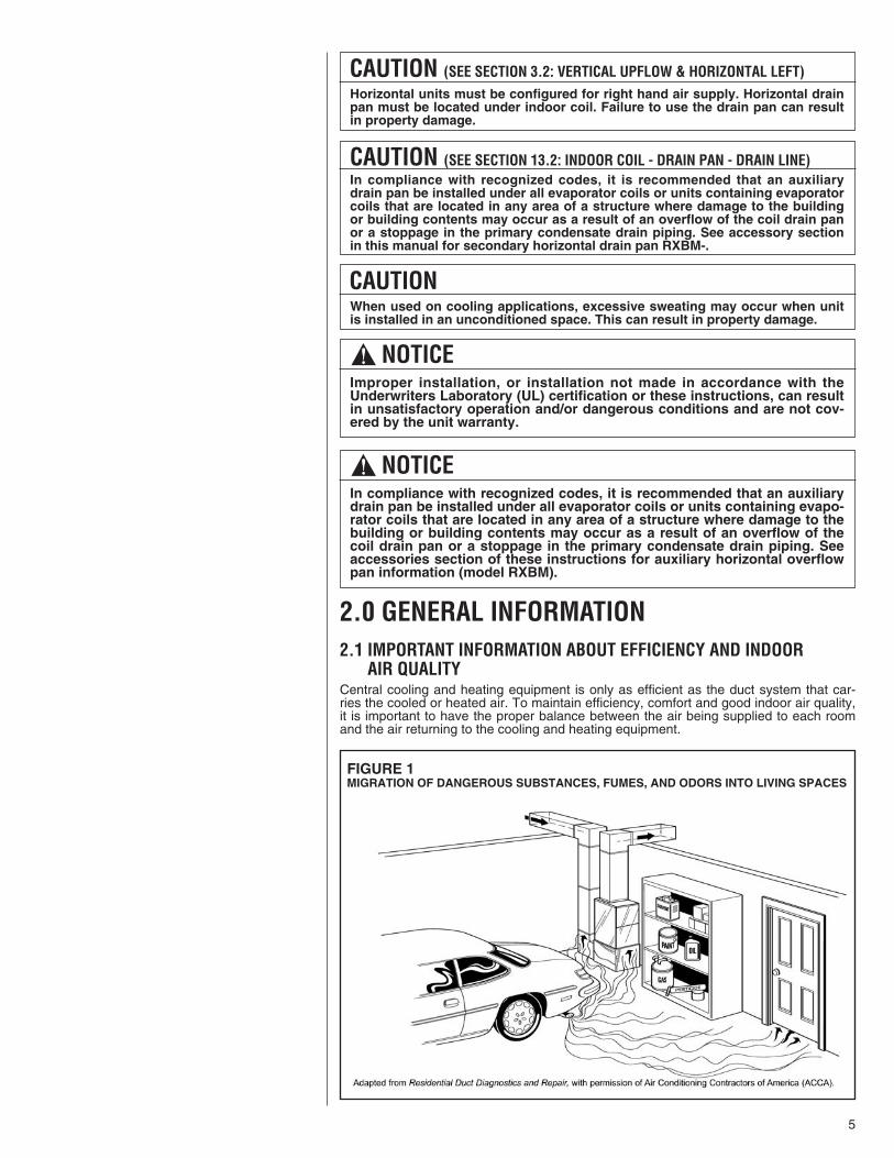
2.0 GENERAL INFORMATION2.1 IMPORTANT INFORMATION ABOUT EFFICIENCY AND INDOOR2.1 AIR QUALITYCentral cooling and heating equipment is only as efficient as the duct system that car-ries the cooled or heated air. To maintain efficiency, comfort and good indoor air quality,it is important to have the proper balance between the air being supplied to each roomand the air returning to the cooling and heating equipment.
CAUTION (SEE SECTION 3.2: VERTICAL UPFLOW & HORIZONTAL LEFT)Horizontal units must be configured for right hand air supply. Horizontal drainpan must be located under indoor coil. Failure to use the drain pan can resultin property damage.
5
CAUTION (SEE SECTION 13.2: INDOOR COIL - DRAIN PAN - DRAIN LINE)In compliance with recognized codes, it is recommended that an auxiliarydrain pan be installed under all evaporator coils or units containing evaporatorcoils that are located in any area of a structure where damage to the buildingor building contents may occur as a result of an overflow of the coil drain panor a stoppage in the primary condensate drain piping. See accessory sectionin this manual for secondary horizontal drain pan RXBM-.
CAUTIONWhen used on cooling applications, excessive sweating may occur when unitis installed in an unconditioned space. This can result in property damage.
! NOTICEImproper installation, or installation not made in accordance with theUnderwriters Laboratory (UL) certification or these instructions, can resultin unsatisfactory operation and/or dangerous conditions and are not cov-ered by the unit warranty.
! NOTICEIn compliance with recognized codes, it is recommended that an auxiliarydrain pan be installed under all evaporator coils or units containing evapo-rator coils that are located in any area of a structure where damage to thebuilding or building contents may occur as a result of an overflow of thecoil drain pan or a stoppage in the primary condensate drain piping. Seeaccessories section of these instructions for auxiliary horizontal overflowpan information (model RXBM).
FIGURE 1MIGRATION OF DANGEROUS SUBSTANCES, FUMES, AND ODORS INTO LIVING SPACES
6
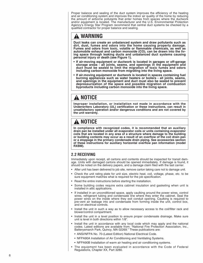
Proper balance and sealing of the duct system improves the efficiency of the heatingand air conditioning system and improves the indoor air quality of the home by reducingthe amount of airborne pollutants that enter homes from spaces where the ductworkand/or equipment is located. The manufacturer and the U.S. Environmental ProtectionAgency’s Energy Star Program recommend that central duct systems be checked by aqualified contractor for proper balance and sealing.
2.2 RECEIVINGImmediately upon receipt, all cartons and contents should be inspected for transit dam-age. Units with damaged cartons should be opened immediately. If damage is found, itshould be noted on the delivery papers, and a damage claim filed with the last carrier. • After unit has been delivered to job site, remove carton taking care not to damage unit. • Check the unit rating plate for unit size, electric heat, coil, voltage, phase, etc. to be
sure equipment matches what is required for the job specification. • Read the entire instructions before starting the installation. • Some building codes require extra cabinet insulation and gasketing when unit is
installed in attic applications. • If installed in an unconditioned space, apply caulking around the power wires, control
wires, refrigerant tubing and condensate line where they enter the cabinet. Seal thepower wires on the inside where they exit conduit opening. Caulking is required topre-vent air leakage into and condensate from forming inside the unit, control box,and on electrical controls.
• Install the unit in such a way as to allow necessary access to the coil/filter rack andblower/control compartment.
• Install the unit in a level position to ensure proper condensate drainage. Make sureunit is level in both directions within 1/8”.
• Install the unit in accordance with any local code which may apply and the nationalcodes. Latest editions are available from: “National Fire Protection Association, Inc.,Batterysmarch Park, Quincy, MA 02269.” These publications are: • ANSI/NFPA No. 70-(Latest Edition) National Electrical Code. • NFPA90A Installation of Air Conditioning and Ventilating Systems. • NFPA90B Installation of warm air heating and air conditioning systems.
• The equipment has been evaluated in accordance with the Code of FederalRegulations, Chapter XX, Part 3280.
! WARNINGDuct leaks can create an unbalanced system and draw pollutants such asdirt, dust, fumes and odors into the home causing property damage.Fumes and odors from toxic, volatile or flammable chemicals, as well asautomobile exhaust and carbon monoxide (CO), can be drawn into the liv-ing space through leaking ducts and unbalanced duct systems causingpersonal injury or death (see Figure 1). • If air-moving equipment or ductwork is located in garages or off-garage
storage areas - all joints, seams, and openings in the equipment andduct must be sealed to limit the migration of toxic fumes and odorsincluding carbon monoxide from migrating into the living space.
• If air-moving equipment or ductwork is located in spaces containing fuelburning appliances such as water heaters or boilers - all joints, seams,and openings in the equipment and duct must also be sealed to preventdepressurization of the space and possible migration of combustionbyproducts including carbon monoxide into the living space.
! NOTICEImproper installation, or installation not made in accordance with theUnderwriters Laboratory (UL) certification or these instructions, can result inunsatisfactory operation and/or dangerous conditions and are not covered bythe unit warranty.
! NOTICEIn compliance with recognized codes, it is recommended that an auxiliarydrain pan be installed under all evaporator coils or units containing evaporatorcoils that are located in any area of a structure where damage to the buildingor building contents may occur as a result of an overflow of the coil drain panor a stoppage in the primary condensate drain piping. See accessories sectionof these instructions for auxiliary horizontal overflow pan information (modelRXBM).
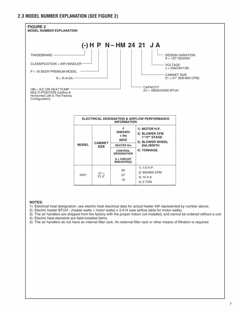
FIGURE 2MODEL NUMBER EXPLANATION
(-) H P N – HM 24 21 J ATRADEBRAND
CLASSIFICATION = AIR HANDLER
P = 18 SEER PREMIUM MODEL
N = R-410A
HM = A/C OR HEAT PUMPMULTI-POSITION (Upflow &Horizontal Left Is The FactoryConfiguration)
DESIGN VARIATIONA = 1ST DESIGN
VOLTAGEJ = 208/240/1/60
CABINET SIZE21 = 21" (600-800 CFM)
CAPACITY24 = 18000/24000 BTUH
NOTES:1) Electrical heat designation: see electric heat electrical data for actual heater kW represented by number above.2) Electric heater BTUH - (heater watts + motor watts) x 3.414 (see airflow table for motor watts).3) The air handlers are shipped from the factory with the proper indoor coil installed, and cannot be ordered without a coil.4) Electric heat elements are field-installed items.5) The air handlers do not have an internal filter rack. An external filter rack or other means of filtration is required.
2.3 MODEL NUMBER EXPLANATION (SEE FIGURE 2)
1) MOTOR H.P.
2) BLOWER CFM1ST/2ND STAGE
3) BLOWER WHEELDIA./WIDTH
4) TONNAGE
J208/240V
1 PH60HZ
CABINETSIZEMODEL
CONTROLDESIGNATION
S = CIRCUITBREAKER(S)
2421 21 = 21.0"
05
07
10
1) 1/3 H.P.
2) 600/800 CFM
3) 10 X 8
4) 2-TON
ELECTRICAL DESIGNATION & AIRFLOW PERFORMANCEINFORMATION
HEATER Kw
7
8
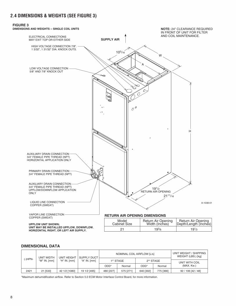
2.4 DIMENSIONS & WEIGHTS (SEE FIGURE 3)
FIGURE 3DIMENSIONS AND WEIGHTS -- SINGLE COIL UNITS
DIMENSIONAL DATA
A-1038-01
NOTE: 24" CLEARANCE REQUIREDIN FRONT OF UNIT FOR FILTERAND COIL MAINTENANCE.ELECTRICAL CONNECTIONS
MAY EXIT TOP OR EITHER SIDE
HIGH VOLTAGE CONNECTION 7/8".1 3/32", 1 31/32" DIA. KNOCK OUTS.
LOW VOLTAGE CONNECTION5/8" AND 7/8" KNOCK OUT
AUXILIARY DRAIN CONNECTION3/4" FEMALE PIPE THREAD (NPT)HORIZONTAL APPLICATION ONLY
PRIMARY DRAIN CONNECTION3/4" FEMALE PIPE THREAD (NPT)
AUXILIARY DRAIN CONNECTION3/4" FEMALE PIPE THREAD (NPT)UPFLOW/DOWNFLOW APPLICATIONONLY
LIQUID LINE CONNECTIONCOPPER (SWEAT)
VAPOR LINE CONNECTIONCOPPER (SWEAT)
2111/16
105/16
SUPPLY AIR
W
A
H
191/2RETURN AIR OPENING
UPFLOW UNIT SHOWN;UNIT MAY BE INSTALLED UPFLOW, DOWNFLOW.HORIZONTAL RIGHT, OR LEFT AIR SUPPLY.
Model Return Air Opening Return Air OpeningCabinet Size Width (Inches) Depth/Length (Inches)
21 193⁄8 191⁄2
RETURN AIR OPENING DIMENSIONS
(-)HPN- UNIT WIDTH“W” IN. [mm]
UNIT HEIGHT“H” IN. [mm]
SUPPLY DUCT“A” IN. [mm]
ODD* ODD*Normal Normal
1ST STAGE 2ND STAGE
NOMINAL COIL AIRFLOW [L/s]
UNIT WITH COIL(MAX. Kw.)
UNIT WEIGHT / SHIPPINGWEIGHT (LBS.) [kg]
*Maximum dehumidification airflow. Refer to Section 5.0 ECM Motor Interface Control Board, for more information.
2421 21 [533] 42 1/2 [1080] 19 1/2 [495] 480 [227] 575 [271] 640 [302] 775 [366] 92 / 106 [42 / 48]
9
2.5 CLEARANCES• All units are designed for “0” inches clearance to combustible material on all cabinet
surfaces.
• Some units require supply duct clearances and combustible floor bases depending onthe heating kW. The following table should be used to determine these requirements:Units with electric heating kW above that listed in the table require a one inch clear-ance to combustible material for the first three feet of supply plenum and ductwork.Additionally, if these units are installed downflow, a combustible floor base isrequired. See Accessories for Combustible Floor Base RXHB-XX.Units with electric heating kW equal to or less than the values listed in the table donot require supply ductwork clearances or combustible floor bases.
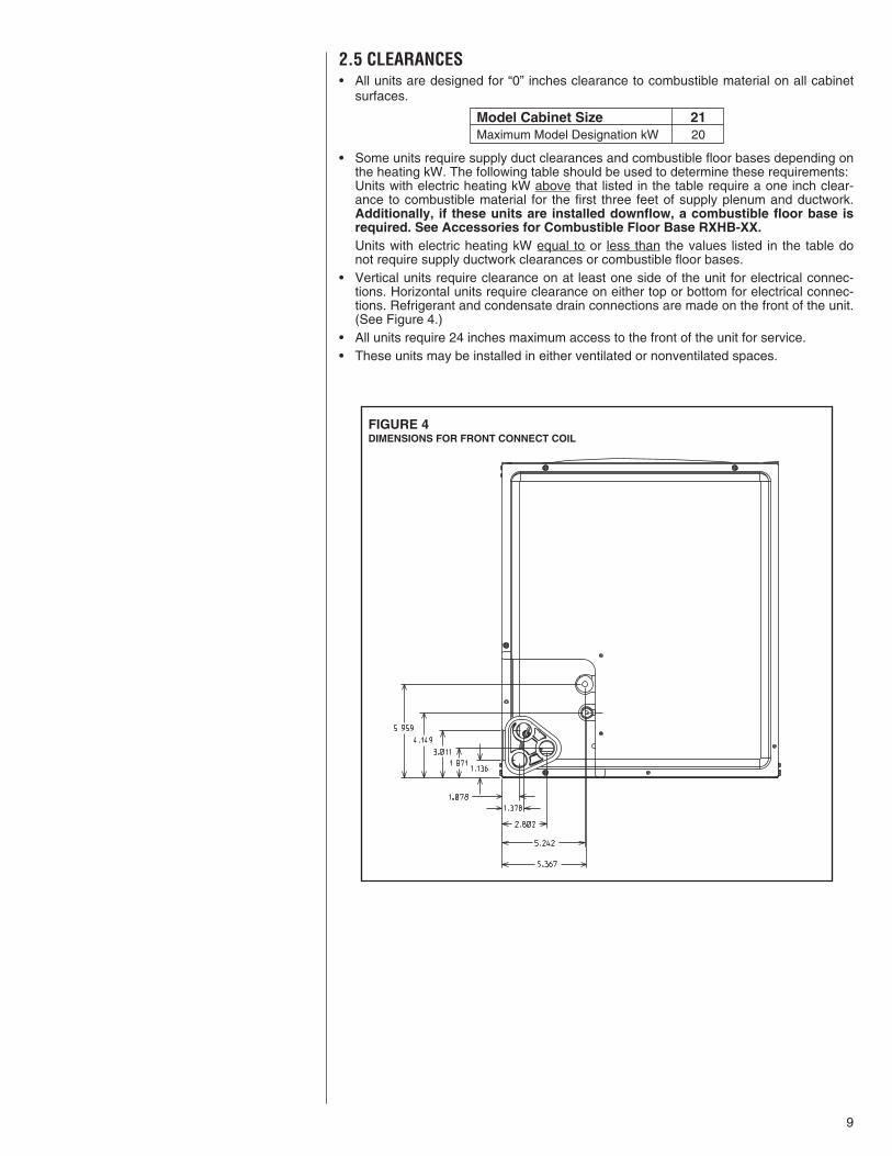
• Vertical units require clearance on at least one side of the unit for electrical connec-tions. Horizontal units require clearance on either top or bottom for electrical connec-tions. Refrigerant and condensate drain connections are made on the front of the unit.(See Figure 4.)
• All units require 24 inches maximum access to the front of the unit for service.• These units may be installed in either ventilated or nonventilated spaces.
FIGURE 4DIMENSIONS FOR FRONT CONNECT COIL
Model Cabinet Size 21Maximum Model Designation kW 20
10
3.0 APPLICATIONS3.1 ZONING SYSTEMSThe manufacturer does not currently provide or support zoning. However, zoning systemscan be installed with a variable speed air-handler as long as the zoning equipment manu-facturers specifications and installation instructions are met and followed.The preferred zoning method is to use a “bypass” system which is properly installed formaximum efficiency. In these systems, excess air is routed back through the system tobe used again – this is opposed to a “dump” system in which excess air is routed to azone where it is expected tht the extra heat or cooling would be least noticed.If installed as a “bypass” system, the installation must have an optional freeze statinstalled to prevent the coil from icing with excess bypass cooling. Also, if the zoningequipment manufacturer provides a limit switch (usually provided by the zoning manufac-turer), this limit must be installed in the system to prevent the furnace from overheating.
3.2 VERTICAL UPFLOW AND HORIZONTAL LEFTThe air handler unit is factory shipped for vertical upflow and horizontal left application.
• If return air is to be ducted, install duct flush with floor. Use fireproof resilient gasket 1/8to 1/4 in. thick between duct, unit and floor. Set unit on floor over opening.
• Support along the length of the unit, all units installed horizontally. Do not support orsuspend unit from both ends without support in the center of the cabinet. If unit is tobe supported or suspended from corners, run two reinforcing rails length of unit andsupport or suspend from reinforcing rails.
• Secondary drain pan kits RXBM- are required when the unit is configured for the hori-zontal left position over a finished ceiling and/or living space. (See Section 15.0:Accessories - Kits - Parts.)
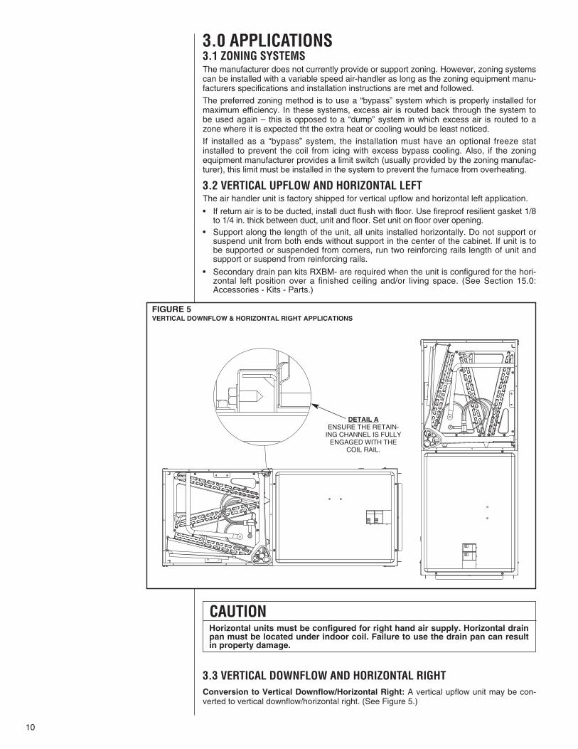
3.3 VERTICAL DOWNFLOW AND HORIZONTAL RIGHTConversion to Vertical Downflow/Horizontal Right: A vertical upflow unit may be con-verted to vertical downflow/horizontal right. (See Figure 5.)
FIGURE 5VERTICAL DOWNFLOW & HORIZONTAL RIGHT APPLICATIONS
CAUTIONHorizontal units must be configured for right hand air supply. Horizontal drainpan must be located under indoor coil. Failure to use the drain pan can resultin property damage.
DETAIL AENSURE THE RETAIN-
ING CHANNEL IS FULLYENGAGED WITH THE
COIL RAIL.
11
• Remove the indoor coil.
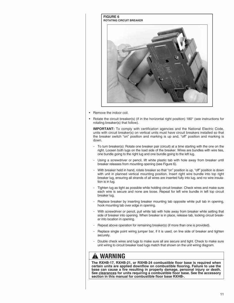
• Rotate the circuit breaker(s) (if in the horizontal right position) 180° (see instructions forrotating breaker(s) that follow).
IMPORTANT: To comply with certification agencies and the National Electric Code,units with circuit breaker(s) on vertical units must have circuit breakers installed so thatthe breaker switch “on” position and marking is up and, “off” position and marking isdown.
- To turn breaker(s): Rotate one breaker pair (circuit) at a time starting with the one on theright. Loosen both lugs on the load side of the breaker. Wires are bundles with wire ties,one bundle going to the right lug and one bundle going to the left lug.
- Using a screwdriver or pencil, lift white plastic tab with hole away from breaker untilbreaker releases from mounting opening (see Figure 6).
- With breaker held in hand, rotate breaker so that “on” position is up, “off” position is downwith unit in planned vertical mounting position. Insert right wire bundle into top rightbreaker lug, ensuring all strands of all wires are inserted fully into lug, and no wire insula-tion is in lug.
- Tighten lug as tight as possible while holding circuit breaker. Check wires and make sureeach wire is secure and none are loose. Repeat for left wire bundle in left top circuitbreaker lug.
- Replace breaker by inserting breaker mounting tab opposite white pull tab in opening,hook mounting tab over edge in opening.
- With screwdriver or pencil, pull white tab with hole away from breaker while setting thatside of breaker into opening. When breaker is in place, release tab, locking circuit break-er into location in opening.
- Repeat above operation for remaining breaker(s) (if more than one is provided).
- Replace single point wiring jumper bar, if it is used, on line side of breaker and tightensecurely.
- Double check wires and lugs to make sure all are secure and tight. Check to make sureunit wiring to circuit breaker load lugs match that shown on the unit wiring diagram.
FIGURE 6ROTATING CIRCUIT BREAKER
! WARNINGThe RXHB-17, RXHB-21, or RXHB-24 combustible floor base is required whencertain units are applied downflow on combustible flooring. Failure to use thebase can cause a fire resulting in property damage, personal injury or death.See clearances for units requiring a combustible floor base. See the accessorysection in this manual for combustible floor base RXHB-.
• Rotate unit into the downflow position, with the coil compartment on top and the blower com-partment on bottom.
• Reinstall the indoor coil 180° from original position. Ensure the retaining channel is fullyengaged with the coil rail. (See Figure 5, Detail A.)
• Secondary drain pan kits RXBM- are required when the unit is configured for the hori-zontal right position over a finished ceiling and/or living space. (See Section 15.0:Accessories - Kits - Parts.)
IMPORTANT: Units cannot be installed horizontally laying on or suspended from theback of the unit.
4.0 ELECTRICAL WIRING
Field wiring must comply with the National Electric Code (C.E.C. in Canada) and anyapplicable local ordinance.
4.1 POWER WIRINGIt is important that proper electrical power is available for connection to the unit modelbeing installed. See the unit nameplate, wiring diagram and electrical data in the installa-tion instructions.
• If required, install a branch circuit disconnect of adequate size, located within sight of,and readily accessible to the unit.
• IMPORTANT: After the Electric Heater is installed, units may be equipped with one,two, or three 60 amp. circuit breakers. These breaker(s) protect the internal wiring inthe event of a short circuit and serve as a disconnect. Circuit breakers installed withinthe unit do not provide over-current protection of the supply wiring and therefore maybe sized larger than the branch circuit protection.
• Supply circuit power wiring must be 75°C minimum copper conductors only. SeeElectrical Data in this section for ampacity, wire size and circuit protector requirement.Supply circuit protective devices may be either fuses or “HACR” type circuit breakers.
• Power wiring may be connected to either the right, left side or top. Three 7/8”, 13/32”,131/32” dia. concentric knockouts are provided for connection of power wiring to unit.
• Power wiring is connected to the power terminal block(s) in unit control compartment.
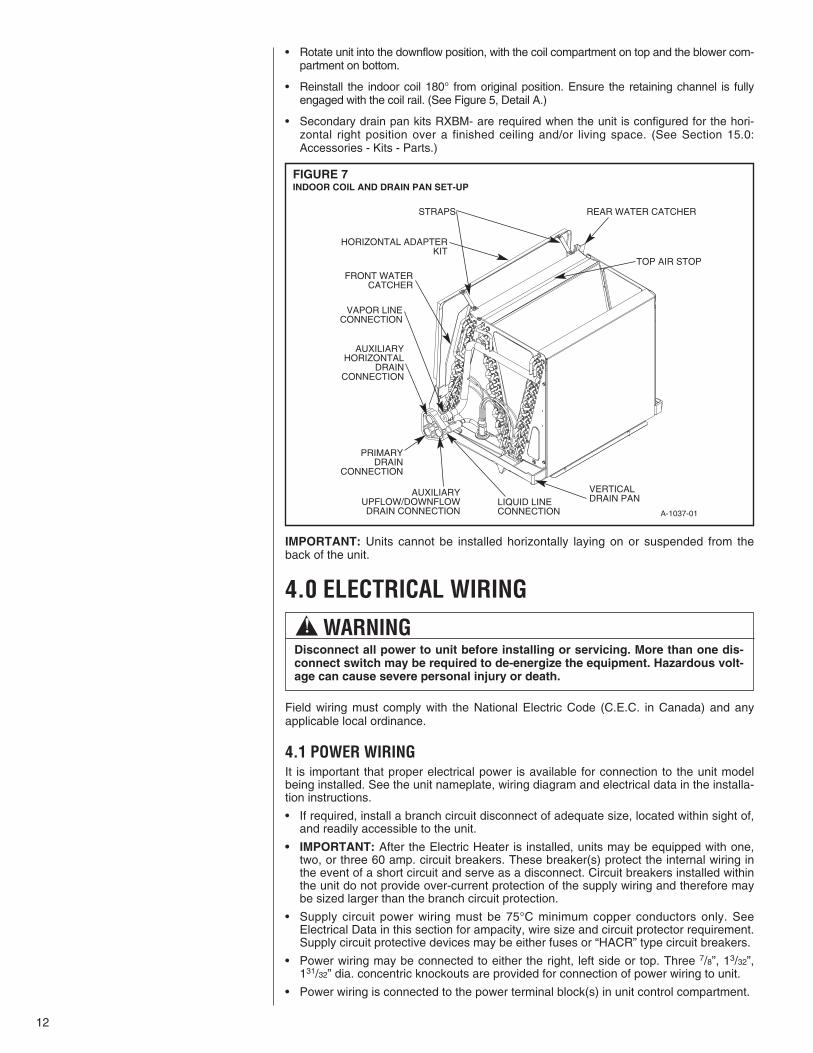
FIGURE 7INDOOR COIL AND DRAIN PAN SET-UP
12
! WARNINGDisconnect all power to unit before installing or servicing. More than one dis-connect switch may be required to de-energize the equipment. Hazardous volt-age can cause severe personal injury or death.
A-1037-01
HORIZONTAL ADAPTERKIT
REAR WATER CATCHER
TOP AIR STOP
STRAPS
VAPOR LINECONNECTION
FRONT WATERCATCHER
PRIMARYDRAIN
CONNECTION
LIQUID LINECONNECTION
VERTICALDRAIN PAN
AUXILIARYHORIZONTAL
DRAINCONNECTION
AUXILIARYUPFLOW/DOWNFLOWDRAIN CONNECTION
13
4.2 CONTROL WIRINGIMPORTANT: Class 2 low voltage control wire should not be run in conduit with powerwiring and must be separated from power wiring, unless Class 1 wire of proper voltagerating is used.
• Low voltage control wiring should be 18 AWG color-coded (105°C minimum). Forlengths longer than 100 ft., 16 AWG wire should be used.
• Low voltage control connections are made by extending wires from top of air handlerusing wire nuts.
• See wiring diagrams attached to indoor and outdoor sections to be connected
• Do not leave excess field control wiring inside unit, pull excess control wire to outsideof unit and provide strain relief for field control wiring on inside of cabinet at pointwiring penetrates cabinet.
• Make sure, after installation, separation of control wiring and power wiring has beenmaintained.
4.3 GROUNDING
• Grounding may be accomplished by grounding metal conduit when installed in accor-dance with electrical codes to the unit cabinet.
• Grounding may also be accomplished by attaching ground wire(s) to ground lug(s)provided in the unit wiring compartment.
• Ground lug(s) are located close to wire entrance on left side of unit (upflow). Lug(s)may be moved to marked locations near wire entrance on right side of unit (upflow), ifalternate location is more convenient.
• Use of multiple supply circuits require grounding of each circuit to lug(s) provided inunit.
! WARNINGThe unit must be permanently grounded. Failure to do so can result in electri-cal shock causing personal injury or death.
4.5 BLOWER MOTOR ELECTRICAL DATA
2 1/3 208/230 1 60 300-1100 1.7 4.0 15
NOMINALCOOLING
CAPACITY (TONS)HP Voltage Phase Hertz RPM Circuit
AMPS
MinimumCircuit
Ampacity
Max. CircuitProtector
14
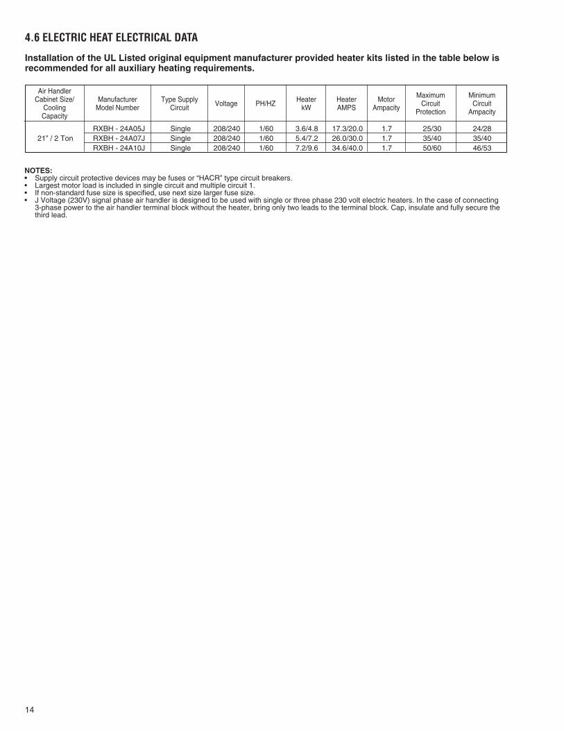
RXBH - 24A05J Single 208/240 1/60 3.6/4.8 17.3/20.0 1.7 25/30 24/2821” / 2 Ton RXBH - 24A07J Single 208/240 1/60 5.4/7.2 26.0/30.0 1.7 35/40 35/40
RXBH - 24A10J Single 208/240 1/60 7.2/9.6 34.6/40.0 1.7 50/60 46/53
Air HandlerCabinet Size/
CoolingCapacity
ManufacturerModel Number
Type SupplyCircuit Voltage PH/HZ Heater
kWHeaterAMPS
MotorAmpacity
MaximumCircuit
Protection
MinimumCircuit
Ampacity
4.6 ELECTRIC HEAT ELECTRICAL DATA
NOTES:• Supply circuit protective devices may be fuses or “HACR” type circuit breakers.• Largest motor load is included in single circuit and multiple circuit 1.• If non-standard fuse size is specified, use next size larger fuse size.• J Voltage (230V) signal phase air handler is designed to be used with single or three phase 230 volt electric heaters. In the case of connecting
3-phase power to the air handler terminal block without the heater, bring only two leads to the terminal block. Cap, insulate and fully secure thethird lead.
Installation of the UL Listed original equipment manufacturer provided heater kits listed in the table below isrecommended for all auxiliary heating requirements.
15
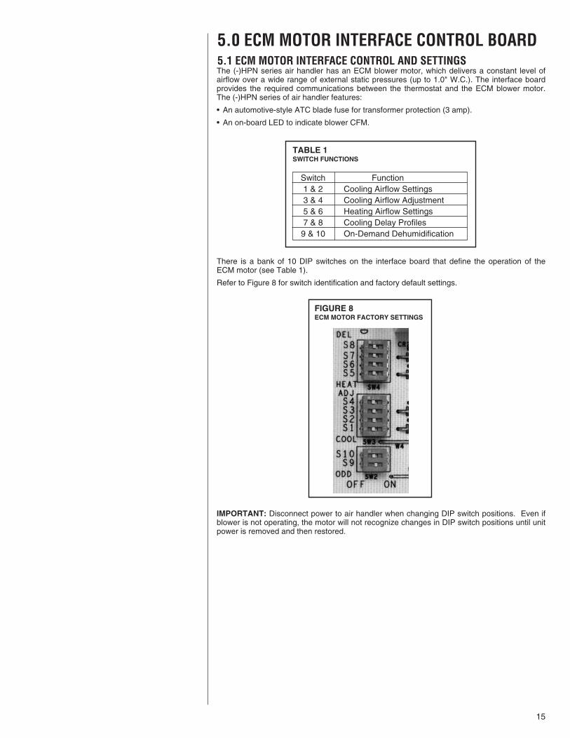
5.0 ECM MOTOR INTERFACE CONTROL BOARD5.1 ECM MOTOR INTERFACE CONTROL AND SETTINGSThe (-)HPN series air handler has an ECM blower motor, which delivers a constant level ofairflow over a wide range of external static pressures (up to 1.0" W.C.). The interface boardprovides the required communications between the thermostat and the ECM blower motor.The (-)HPN series of air handler features:
• An automotive-style ATC blade fuse for transformer protection (3 amp).
• An on-board LED to indicate blower CFM.
There is a bank of 10 DIP switches on the interface board that define the operation of theECM motor (see Table 1).
Refer to Figure 8 for switch identification and factory default settings.
IMPORTANT: Disconnect power to air handler when changing DIP switch positions. Even ifblower is not operating, the motor will not recognize changes in DIP switch positions until unitpower is removed and then restored.
FIGURE 8ECM MOTOR FACTORY SETTINGS
TABLE 1SWITCH FUNCTIONS
Switch Function1 & 2 Cooling Airflow Settings3 & 4 Cooling Airflow Adjustment5 & 6 Heating Airflow Settings7 & 8 Cooling Delay Profiles
9 & 10 On-Demand Dehumidification
16
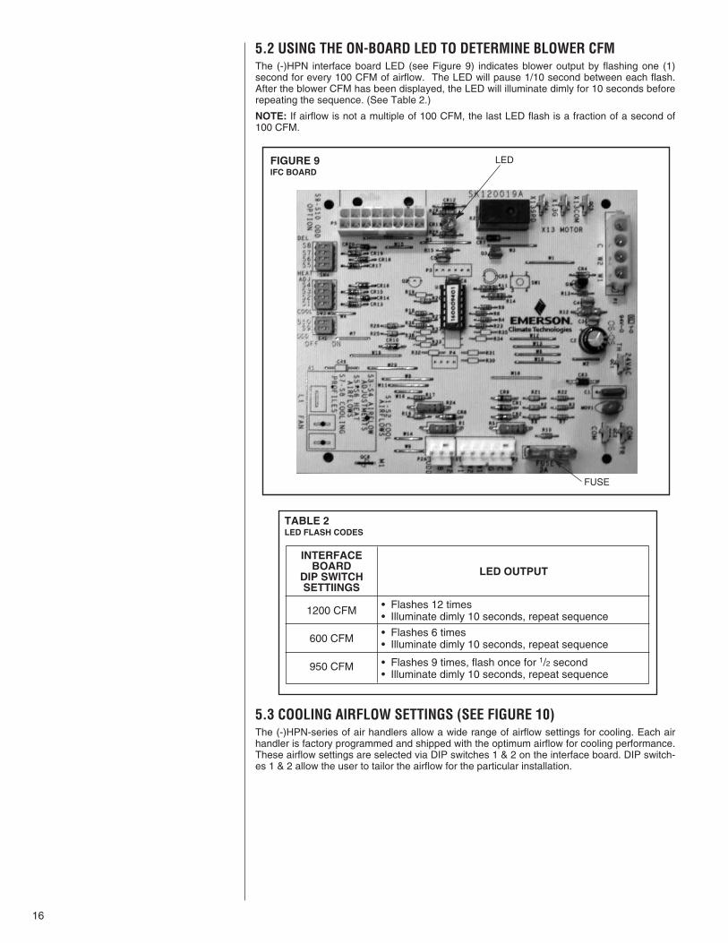
5.2 USING THE ON-BOARD LED TO DETERMINE BLOWER CFMThe (-)HPN interface board LED (see Figure 9) indicates blower output by flashing one (1)second for every 100 CFM of airflow. The LED will pause 1/10 second between each flash.After the blower CFM has been displayed, the LED will illuminate dimly for 10 seconds beforerepeating the sequence. (See Table 2.)
NOTE: If airflow is not a multiple of 100 CFM, the last LED flash is a fraction of a second of100 CFM.
5.3 COOLING AIRFLOW SETTINGS (SEE FIGURE 10)The (-)HPN-series of air handlers allow a wide range of airflow settings for cooling. Each airhandler is factory programmed and shipped with the optimum airflow for cooling performance.These airflow settings are selected via DIP switches 1 & 2 on the interface board. DIP switch-es 1 & 2 allow the user to tailor the airflow for the particular installation.
5.4 COOLING AIRFLOW ADJUSTMENTS
TABLE 2LED FLASH CODES
INTERFACEBOARD
DIP SWITCHSETTIINGS
1200 CFM
600 CFM
950 CFM
LED OUTPUT
• Flashes 12 times• Illuminate dimly 10 seconds, repeat sequence
• Flashes 6 times• Illuminate dimly 10 seconds, repeat sequence
• Flashes 9 times, flash once for 1/2 second• Illuminate dimly 10 seconds, repeat sequence
FIGURE 9IFC BOARD
LED
FUSE
17
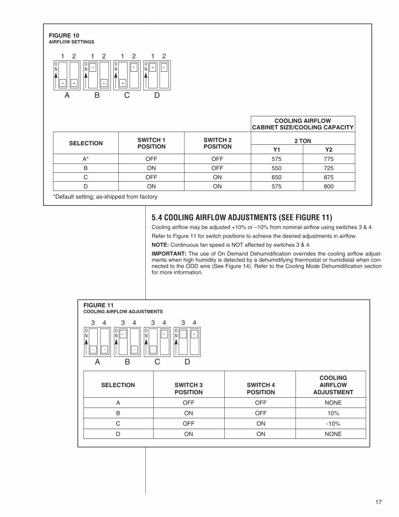
5.4 COOLING AIRFLOW ADJUSTMENTS (SEE FIGURE 11)Cooling airflow may be adjusted +10% or –10% from nominal airflow using switches 3 & 4.
Refer to Figure 11 for switch positions to achieve the desired adjustments in airflow.
NOTE: Continuous fan speed is NOT affected by switches 3 & 4.
IMPORTANT: The use of On Demand Dehumidification overrides the cooling airflow adjust-ments when high humidity is detected by a dehumidifying thermostat or humidistat when con-nected to the ODD wire (See Figure 14). Refer to the Cooling Mode Dehumidification sectionfor more information.
A* OFF OFF 575 775
B ON OFF 550 725
C OFF ON 650 875
D ON ON 575 800
FIGURE 10AIRFLOW SETTINGS
SELECTION SWITCH 1POSITION
SWITCH 2POSITION
2 TONY1 Y2
COOLING AIRFLOWCABINET SIZE/COOLING CAPACITY
ON
ON
ON
ON
A
1 2 1 2 1 2 1 2
B C D
FIGURE 11COOLING AIRFLOW ADJUSTMENTS
COOLINGSELECTION SWITCH 3 SWITCH 4 AIRFLOW
POSITION POSITION ADJUSTMENT
A OFF OFF NONE
B ON OFF 10%
C OFF ON -10%
D ON ON NONE
ON
ON
ON
ON
A
3 4 3 4 3 4 3 4
B C D
*Default setting; as-shipped from factory
18
5.5 HEATING AIRFLOW ADJUSTMENTS (HEAT PUMP)The (-)HPN air handler does not allow heating airflow adjustments.
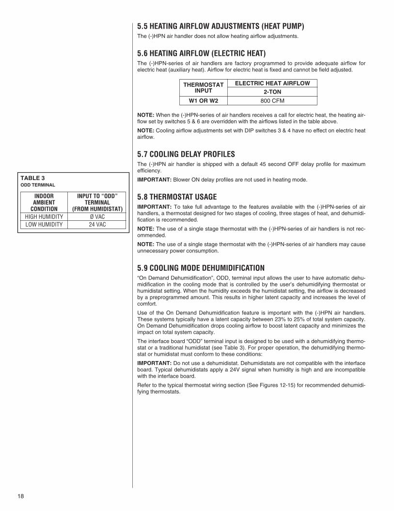
5.6 HEATING AIRFLOW (ELECTRIC HEAT)The (-)HPN-series of air handlers are factory programmed to provide adequate airflow forelectric heat (auxiliary heat). Airflow for electric heat is fixed and cannot be field adjusted.
NOTE: When the (-)HPN-series of air handlers receives a call for electric heat, the heating air-flow set by switches 5 & 6 are overridden with the airflows listed in the table above.
NOTE: Cooling airflow adjustments set with DIP switches 3 & 4 have no effect on electric heatairflow.
5.7 COOLING DELAY PROFILESThe (-)HPN air handler is shipped with a default 45 second OFF delay profile for maximumefficiency.
IMPORTANT: Blower ON delay profiles are not used in heating mode.
5.8 THERMOSTAT USAGEIMPORTANT: To take full advantage to the features available with the (-)HPN-series of airhandlers, a thermostat designed for two stages of cooling, three stages of heat, and dehumidi-fication is recommended.
NOTE: The use of a single stage thermostat with the (-)HPN-series of air handlers is not rec-ommended.
NOTE: The use of a single stage thermostat with the (-)HPN-series of air handlers may causeunnecessary power consumption.
5.9 COOLING MODE DEHUMIDIFICATION“On Demand Dehumidification”, ODD, terminal input allows the user to have automatic dehu-midification in the cooling mode that is controlled by the user’s dehumidifying thermostat orhumidistat setting. When the humidity exceeds the humidistat setting, the airflow is decreasedby a preprogrammed amount. This results in higher latent capacity and increases the level ofcomfort.
Use of the On Demand Dehumidification feature is important with the (-)HPN air handlers.These systems typically have a latent capacity between 23% to 25% of total system capacity.On Demand Dehumidification drops cooling airflow to boost latent capacity and minimizes theimpact on total system capacity.
The interface board “ODD” terminal input is designed to be used with a dehumidifying thermo-stat or a traditional humidistat (see Table 3). For proper operation, the dehumidifying thermo-stat or humidistat must conform to these conditions:
IMPORTANT: Do not use a dehumidistat. Dehumidistats are not compatible with the interfaceboard. Typical dehumidistats apply a 24V signal when humidity is high and are incompatiblewith the interface board.
Refer to the typical thermostat wiring section (See Figures 12-15) for recommended dehumidi-fying thermostats.
TABLE 3ODD TERMINAL
INDOOR INPUT TO “ODD”AMBIENT TERMINAL
CONDITION (FROM HUMIDISTAT)HIGH HUMIDITY Ø VACLOW HUMIDITY 24 VAC
2-TON
800 CFM
ELECTRIC HEAT AIRFLOWTHERMOSTATINPUT
W1 OR W2
19
W2
W1
C
G
(-)HPN AirHandler
Y1 E/W1
Typical Two-Stage Thermostat
OutdoorUnit
Y2
C
R
Y2
Field Installed Line Voltage
-
WIRING INFORMATION
Factory Standard -
ODD
R
Y1
Y2 G W2 R
Y1
C
L
Y
Y/BL
R
BR
W/R
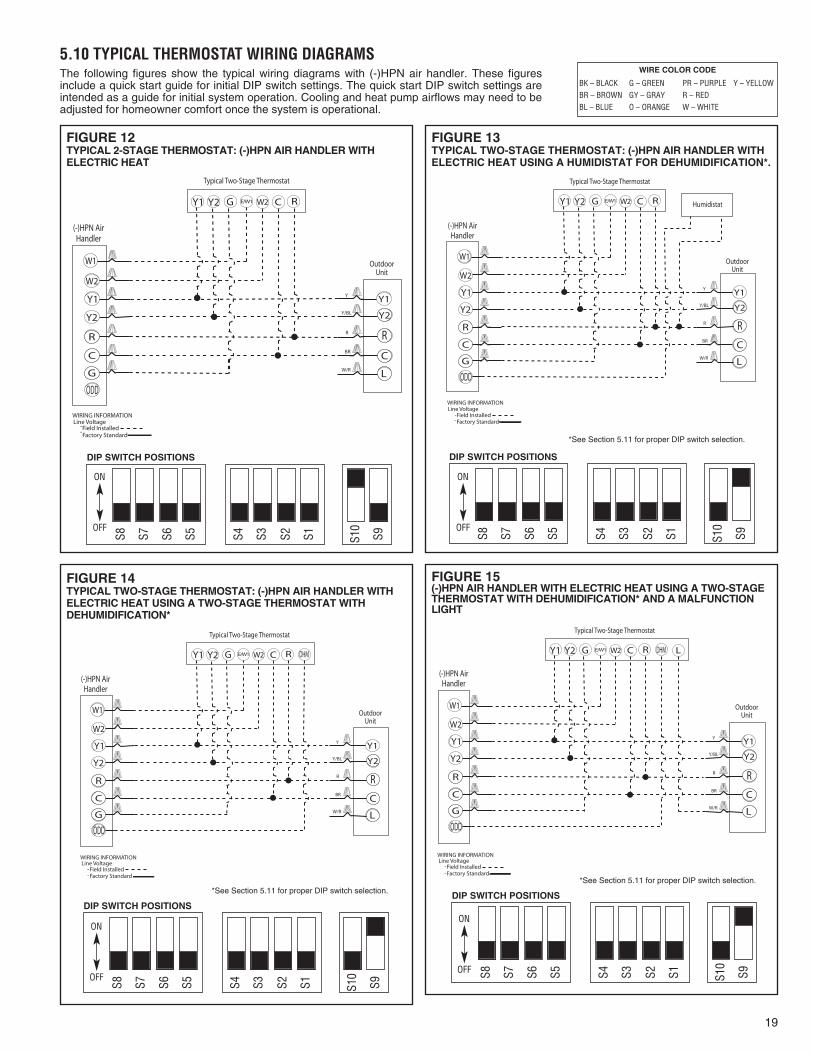
FIGURE 12TYPICAL 2-STAGE THERMOSTAT: (-)HPN AIR HANDLER WITHELECTRIC HEAT
FIGURE 13TYPICAL TWO-STAGE THERMOSTAT: (-)HPN AIR HANDLER WITHELECTRIC HEAT USING A HUMIDISTAT FOR DEHUMIDIFICATION*.
W2
W1
C
G
(-)HPN AirHandler
Y1 E/W1
Typical Two-Stage Thermostat
OutdoorUnit
Y2
C
R
Y2
Field Installed Line Voltage
-
WIRING INFORMATION
Factory Standard -
ODD
R
Y1
Y2 G W2 R
Y1
C
L
Y
Y/BL
R
BR
W/R
Humidistat
FIGURE 14TYPICAL TWO-STAGE THERMOSTAT: (-)HPN AIR HANDLER WITHELECTRIC HEAT USING A TWO-STAGE THERMOSTAT WITHDEHUMIDIFICATION*
W2
W1
C
G
(-)HPN AirHandler
Y1 E/W1
Typical Two-Stage Thermostat
OutdoorUnit
Y2
C
R
Y2
Field Installed Line Voltage
-
WIRING INFORMATION
Factory Standard -
ODD
R
Y1
Y2 G W2 R
Y1
C
L
Y
Y/BL
R
BR
W/R
DHM
W2
W1
C
G
(-)HPN AirHandler
Y1 E/W1
Typical Two-Stage Thermostat
OutdoorUnit
Y2
C
R
Y2
Field Installed Line Voltage
-
WIRING INFORMATION
Factory Standard -
ODD
R
Y1
Y2 G W2 R
Y1
C
L
Y
Y/BL
R
BR
W/R
DHM L
FIGURE 15(-)HPN AIR HANDLER WITH ELECTRIC HEAT USING A TWO-STAGETHERMOSTAT WITH DEHUMIDIFICATION* AND A MALFUNCTIONLIGHT
5.10 TYPICAL THERMOSTAT WIRING DIAGRAMSWIRE COLOR CODE
BK – BLACK G – GREEN PR – PURPLE Y – YELLOWBR – BROWN GY – GRAY R – REDBL – BLUE O – ORANGE W – WHITE
S8 S7 S6 S5 S4 S3 S2 S1 S10
S9 S8 S7 S6 S5 S4 S3 S2 S1 S10
S9
*See Section 5.11 for proper DIP switch selection.
DIP SWITCH POSITIONS DIP SWITCH POSITIONS
ON
OFF S8 S7 S6 S5 S4 S3 S2 S1 S10
S9
DIP SWITCH POSITIONS
S8 S7 S6 S5 S4 S3 S2 S1 S10
S9
DIP SWITCH POSITIONS
*See Section 5.11 for proper DIP switch selection.*See Section 5.11 for proper DIP switch selection.
ON
OFF
ON
OFF
ON
OFF
The following figures show the typical wiring diagrams with (-)HPN air handler. These figuresinclude a quick start guide for initial DIP switch settings. The quick start DIP switch settings areintended as a guide for initial system operation. Cooling and heat pump airflows may need to beadjusted for homeowner comfort once the system is operational.
20
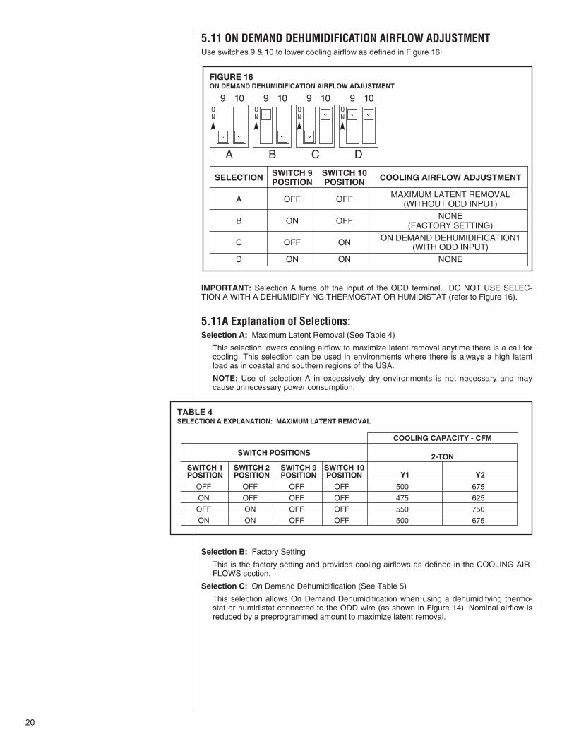
5.11 ON DEMAND DEHUMIDIFICATION AIRFLOW ADJUSTMENTUse switches 9 & 10 to lower cooling airflow as defined in Figure 16:
IMPORTANT: Selection A turns off the input of the ODD terminal. DO NOT USE SELEC-TION A WITH A DEHUMIDIFYING THERMOSTAT OR HUMIDISTAT (refer to Figure 16).
5.11A Explanation of Selections:Selection A: Maximum Latent Removal (See Table 4)
This selection lowers cooling airflow to maximize latent removal anytime there is a call forcooling. This selection can be used in environments where there is always a high latentload as in coastal and southern regions of the USA.
NOTE: Use of selection A in excessively dry environments is not necessary and maycause unnecessary power consumption.
Selection B: Factory Setting
This is the factory setting and provides cooling airflows as defined in the COOLING AIR-FLOWS section.
Selection C: On Demand Dehumidification (See Table 5)
This selection allows On Demand Dehumidification when using a dehumidifying thermo-stat or humidistat connected to the ODD wire (as shown in Figure 14). Nominal airflow isreduced by a preprogrammed amount to maximize latent removal.
TABLE 4SELECTION A EXPLANATION: MAXIMUM LATENT REMOVAL
FIGURE 16ON DEMAND DEHUMIDIFICATION AIRFLOW ADJUSTMENT
ON
ON
ON
ON
A
9 10 9 10 9 10 9 10
B C D
SWITCH 9 SWITCH 10SELECTION POSITION POSITION COOLING AIRFLOW ADJUSTMENT
MAXIMUM LATENT REMOVALA OFF OFF (WITHOUT ODD INPUT)NONEB ON OFF (FACTORY SETTING)
ON DEMAND DEHUMIDIFICATION1C OFF ON (WITH ODD INPUT)D ON ON NONE
SWITCH POSITIONS
SWITCH 1POSITION
SWITCH 2POSITION
SWITCH 9POSITION
SWITCH 10POSITION
COOLING CAPACITY - CFM
2-TON
Y1 Y2
OFF OFF OFF OFF 500 675
ON OFF OFF OFF 475 625
OFF ON OFF OFF 550 750
ON ON OFF OFF 500 675
21
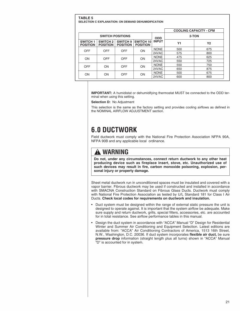
TABLE 5SELECTION C EXPLANATION: ON DEMAND DEHUMIDIFICATION
IMPORTANT: A humidistat or dehumidifying thermostat MUST be connected to the ODD ter-minal when using this setting.
Selection D: No Adjustment
This selection is the same as the factory setting and provides cooling airflows as defined inthe NOMINAL AIRFLOW ADJUSTMENT section.
6.0 DUCTWORKField ductwork must comply with the National Fire Protection Association NFPA 90A,NFPA 90B and any applicable local ordinance.
Sheet metal ductwork run in unconditioned spaces must be insulated and covered with avapor barrier. Fibrous ductwork may be used if constructed and installed in accordancewith SMACNA Construction Standard on Fibrous Glass Ducts. Ductwork must complywith National Fire Protection Association as tested by U/L Standard 181 for Class I AirDucts. Check local codes for requirements on ductwork and insulation.
• Duct system must be designed within the range of external static pressure the unit isdesigned to operate against. It is important that the system airflow be adequate. Makesure supply and return ductwork, grills, special filters, accessories, etc. are accountedfor in total resistance. See airflow performance tables in this manual.
• Design the duct system in accordance with “ACCA” Manual “D” Design for ResidentialWinter and Summer Air Conditioning and Equipment Selection. Latest editions areavailable from: “ACCA” Air Conditioning Contractors of America, 1513 16th Street,N.W., Washington, D.C. 20036. If duct system incorporates flexible air duct, be surepressure drop information (straight length plus all turns) shown in “ACCA” Manual“D” is accounted for in system.
! WARNINGDo not, under any circumstances, connect return ductwork to any other heatproducing device such as fireplace insert, stove, etc. Unauthorized use ofsuch devices may result in fire, carbon monoxide poisoning, explosion, per-sonal injury or property damage.
SWITCH POSITIONS
SWITCH 1POSITION
SWITCH 2POSITION
SWITCH 9POSITION
SWITCH 10POSITION
ODDINPUT
COOLING CAPACITY - CFM
2-TON
Y1 Y2
NONE 500 67524VAC 575 800NONE 475 62524VAC 550 725NONE 550 75024VAC 650 875NONE 500 67524VAC 600 800
OFF OFF OFF ON
ON OFF OFF ON
OFF ON OFF ON
ON ON OFF ON
22
• Supply plenum is attached to the 3/4” duct flanges supplied on the unit around theblower outlet. Flanges are flat for shipping purposes and must be bent up along perfo-rated edge around blower opening. Be sure to bend flanges completely up so they donot interfere with air being discharged from blower.
IMPORTANT: Flanges around blower opening for attaching supply duct must be up outof blower discharge even if not used so they do not restrict airflow from blower.
IMPORTANT: If an elbow is included in the plenum close to the unit, it must not besmaller than the dimensions of the supply duct flange on the unit.
• Some units with electric heaters require 1 in. clearance to supply plenum and branchducts to combustible material for the first 3 feet from the unit. See CLEARANCES.
• A 3/4” return duct flange is supplied on all sides of the air inlet opening of the unit coilcasing. If the unit is to be installed without a coil casing (no indoor coil), a 3/4”flange issupplied on the back and sides of the air inlet opening of the blower casing. No flangeis provided on the front of the opening to the blower casing. If return duct is attachedto the inlet of the blower casing, the front flange of the duct should be run up into theopening or 90° brake made on the front flange to tape to the front of the blower cas-ing.
• IMPORTANT: The front flange on the return duct if connected to the blower casingmust not be screwed into the area where the power wiring is located. Drills or sharpscrew points can damage insulation on wires located inside unit.
• Return duct flanges on blower or coil casing are flat for shipping purposes and mustbe bent out along perforated edge around opening.
• Secure the supply and return ductwork to the unit flanges, using proper fasteners forthe type of duct used and tape the duct-to-unit joint as required to prevent air leaks.
23
7.0 REFRIGERANT CONNECTIONSKeep the coil connections sealed until refrigerant connections are to be made. See theInstallation Instructions for the outdoor unit for details on line sizing, tubing installation,and charging information.
Coil is shipped with a low (5 - 10 PSIG) pressure charge of dry nitrogen. Evacuate thesystem before charging with refrigerant.
Install refrigerant tubing so that it does not block service access to the front of the unit.
Nitrogen should flow through the refrigerant lines while brazing.
Use a brazing shield to protect the cabinet’s paint from being damaged by torch flames.
After the refrigerant connections are made, seal the gap around the connections withpressure sensitive gasket. If necessary, cut the gasket into two pieces for a better seal.
7.1 TEV SENSING BULBIMPORTANT: DO NOT perform any soldering with the TEV bulb attached to any line.
After soldering operations have been completed, clamp the TEV bulb securely on thesuction line at the 10 to 2 o’clock position with the strap provided in the parts bag.
Insulate the TEV sensing bulb and suction line with the provided pressure sensitive insu-lation (size 4” x 7”) and secure with provided wire ties.
IMPORTANT: TEV sensing bulb should be located on a horizontal section of suctionline, just outside of coil box.
7.2 CONDENSATE DRAIN TUBINGConsult local codes or ordinances for specific requirements.
IMPORTANT: When making drain fitting connections to the drain pan, use a thin layer ofTeflon paste, silicone or Teflon tape and install hand tight.
IMPORTANT: When making drain fitting connections to drain pan, do not overtighten.Overtightening fittings can split pipe connetions on the drain pan.
• Install drain lines so they do not block service access to front of the unit. Minimumclearance of 24 inches is required for filter, coil or blower removal and service access.
• Make sure unit is level or pitched slightly toward primary drain connection so thatwater will drain completely from the pan. (See Figure 17.)
• Do not reduce drain line size less than connection size provided on condensate drainpan.
• All drain lines must be pitched downward away from the unit a minimum of 1/8” perfoot of line to ensure proper drainage.
• Do not connect condensate drain line to a closed or open sewer pipe. Run conden-sate to an open drain or outdoors.
• The drain line should be insulated where necessary to prevent sweating and damagedue to condensate forming on the outside surface of the line.
24
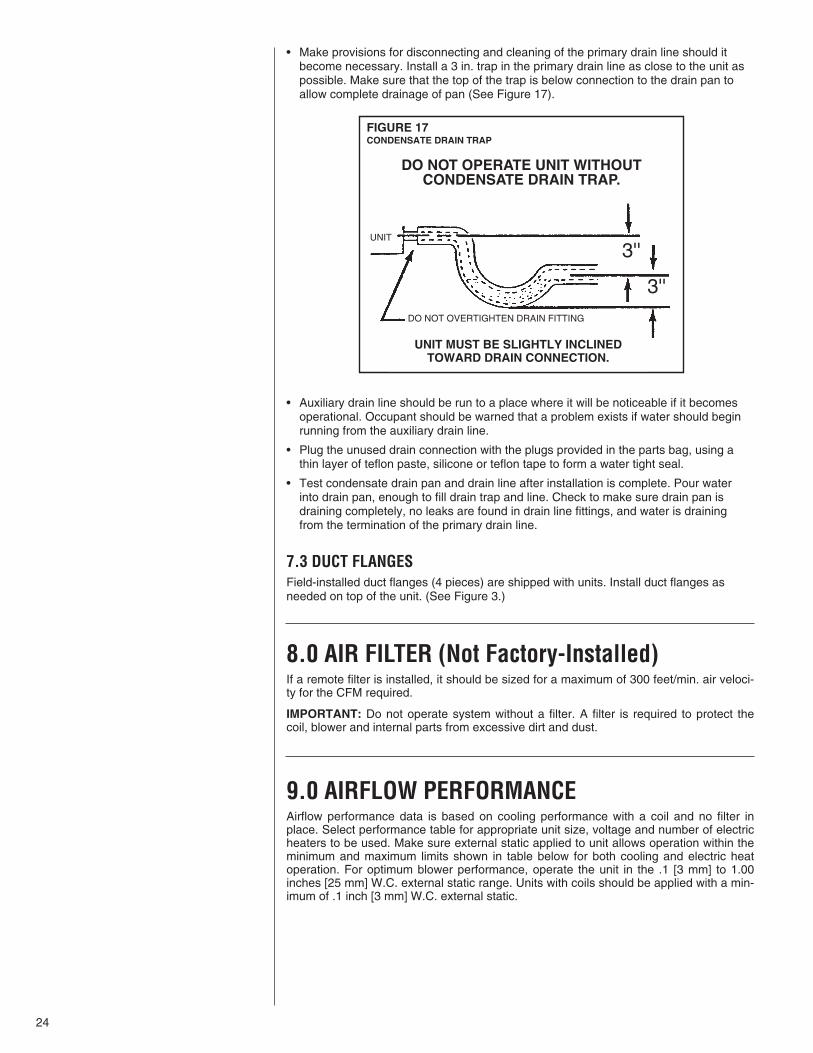
• Make provisions for disconnecting and cleaning of the primary drain line should itbecome necessary. Install a 3 in. trap in the primary drain line as close to the unit aspossible. Make sure that the top of the trap is below connection to the drain pan toallow complete drainage of pan (See Figure 17).
• Auxiliary drain line should be run to a place where it will be noticeable if it becomesoperational. Occupant should be warned that a problem exists if water should beginrunning from the auxiliary drain line.
• Plug the unused drain connection with the plugs provided in the parts bag, using athin layer of teflon paste, silicone or teflon tape to form a water tight seal.
• Test condensate drain pan and drain line after installation is complete. Pour waterinto drain pan, enough to fill drain trap and line. Check to make sure drain pan isdraining completely, no leaks are found in drain line fittings, and water is drainingfrom the termination of the primary drain line.
7.3 DUCT FLANGESField-installed duct flanges (4 pieces) are shipped with units. Install duct flanges asneeded on top of the unit. (See Figure 3.)
8.0 AIR FILTER (Not Factory-Installed)If a remote filter is installed, it should be sized for a maximum of 300 feet/min. air veloci-ty for the CFM required.
IMPORTANT: Do not operate system without a filter. A filter is required to protect thecoil, blower and internal parts from excessive dirt and dust.
9.0 AIRFLOW PERFORMANCEAirflow performance data is based on cooling performance with a coil and no filter inplace. Select performance table for appropriate unit size, voltage and number of electricheaters to be used. Make sure external static applied to unit allows operation within theminimum and maximum limits shown in table below for both cooling and electric heatoperation. For optimum blower performance, operate the unit in the .1 [3 mm] to 1.00inches [25 mm] W.C. external static range. Units with coils should be applied with a min-imum of .1 inch [3 mm] W.C. external static.
FIGURE 17CONDENSATE DRAIN TRAP
DO NOT OPERATE UNIT WITHOUTCONDENSATE DRAIN TRAP.
UNIT MUST BE SLIGHTLY INCLINEDTOWARD DRAIN CONNECTION.
DO NOT OVERTIGHTEN DRAIN FITTING
UNIT
3''
3''
25
10.0 SEQUENCE OF OPERATION10.1 Cooling (cooling only or heat pump)• When the thermostat “calls for cooling,” the circuit between R, G and Y is completed,
causing the blower to energize. This circuit also closes the contactor (CC) in the out-door unit starting the compressor (COMP) and outdoor fan motor (OFM).
10.2 Heating (electric heat only)• When the thermostat “calls for heat,” the circuit between R and W1 is completed, and
the heater sequencer (HR1) is energized. A time delay will follow then: The heatingelements (HE) and the indoor blower motor (IBM) will come on. Units with a secondheater sequencer (HR2) can be connected with the first sequencer (HR1) to W on thethermostat sub-base or connected to a second stage W2 on the sub-base. W1 on the furnace board MUST be connected for heating blower operation.
10.3 EMERGENCY HEAT (electric backup heat)• If selector switch on thermostat is set to the emergency heat position, the heat pump
will be locked out of the heating circuit, and all heating will be electric heat. Jumpershould be placed between W2 and E on the thermostat sub-base so that the electricheat control will transfer to the first stage heat on the thermostat. This will allow theindoor blower to cycle on and off with the electric heat when the fan switch is in theauto position.
10.4 ROOM THERMOSTAT (ANTICIPATOR SETTING)See instructions with outdoor section, condensing unit or heat pump for recommendedroom thermostats.
• On units with one electric heat sequencer (HR1) (see wiring diagram on unit), heatanticipator setting should be .16.
• On units with two electric heat sequencers (HR1 & HR2) (see wiring diagram on unit),heat anticipator setting should be .32 if both are connected to same stage on thermo-stat. Setting should be .16 if (HR1 &HR2) are connected to separate stages.
NOTE: Some thermostats contain a fixed, non-adjustable heat anticipator. Adjustment isnot permitted.
• The thermostat should be mounted 4 to 5 feet above the floor on an inside wall of theliving room or a hallway that has good air circulation from the other rooms being con-trolled by the thermostat. It is essential that there be free air circulation at the locationof the same average temperature as other rooms being controlled. Movement of airshould not be obstructed by furniture, doors, draperies, etc. The thermostat shouldnot be mounted where it will be affected by drafts, hot or cold water pipes or air ductsin walls, radiant heat from fireplace, lamps, the sun, T.V. or an outside wall. Seeinstruction sheet packaged with thermostat for mounting and installation instructions.
NOTE: Some thermostats, particularly solid-state digital types, contain fixed, non-adjustable heat anticipators and adjustment is not permitted.
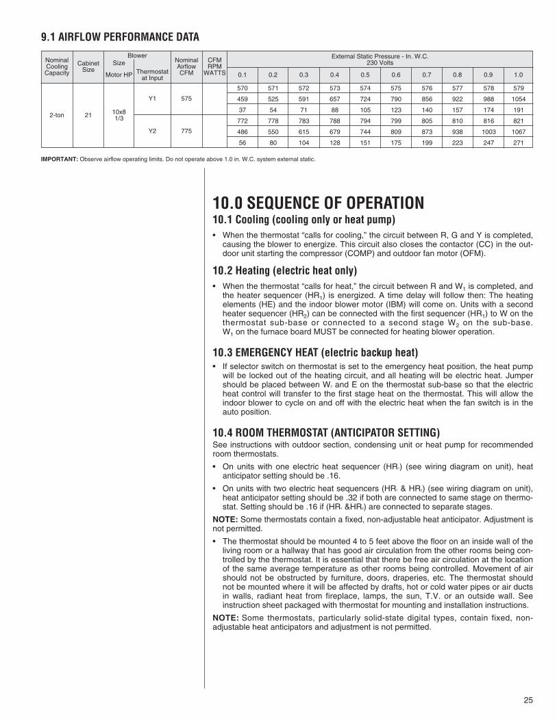
9.1 AIRFLOW PERFORMANCE DATA
IMPORTANT: Observe airflow operating limits. Do not operate above 1.0 in. W.C. system external static.
NominalCoolingCapacity
CabinetSize
Motor HP Thermostatat Input
NominalAirflowCFM
575Y1
Y2 775
10x81/3212-ton
CFMRPM
WATTS 0.1 0.2 0.3 0.4 0.5 0.6 0.7 0.8 0.9 1.0
External Static Pressure - In. W.C.230 VoltsSize
Blower
570 571 572 573 574 575 576 577 578 579
459 525 591 657 724 790 856 922 988 1054
37 54 71 88 105 123 140 157 174 191
772 778 783 788 794 799 805 810 816 821
486 550 615 679 744 809 873 938 1003 1067
56 80 104 128 151 175 199 223 247 271
26
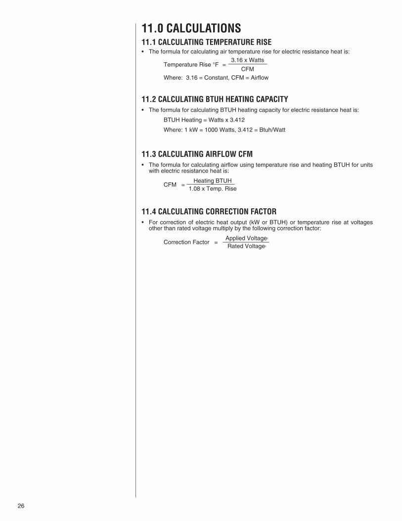
11.0 CALCULATIONS11.1 CALCULATING TEMPERATURE RISE• The formula for calculating air temperature rise for electric resistance heat is:
3.16 x WattsTemperature Rise °F =
CFMWhere: 3.16 = Constant, CFM = Airflow
11.2 CALCULATING BTUH HEATING CAPACITY• The formula for calculating BTUH heating capacity for electric resistance heat is:
BTUH Heating = Watts x 3.412
Where: 1 kW = 1000 Watts, 3.412 = Btuh/Watt
11.3 CALCULATING AIRFLOW CFM• The formula for calculating airflow using temperature rise and heating BTUH for units
with electric resistance heat is:
Heating BTUHCFM =
1.08 x Temp. Rise
11.4 CALCULATING CORRECTION FACTOR• For correction of electric heat output (kW or BTUH) or temperature rise at voltages
other than rated voltage multiply by the following correction factor:
Applied Voltage2
Correction Factor =Rated Voltage2
27
13.0 MAINTENANCEFor continuing high performance, and to minimize possible equipment failure, it isessential that periodic maintenance be performed on this equipment. Consult your localdealer as to the proper frequency of maintenance and the availability of a maintenancecontract.
IMPORTANT: Before performing any service or maintenance procedures, read all“WARNINGS” listed in these installation instructions.
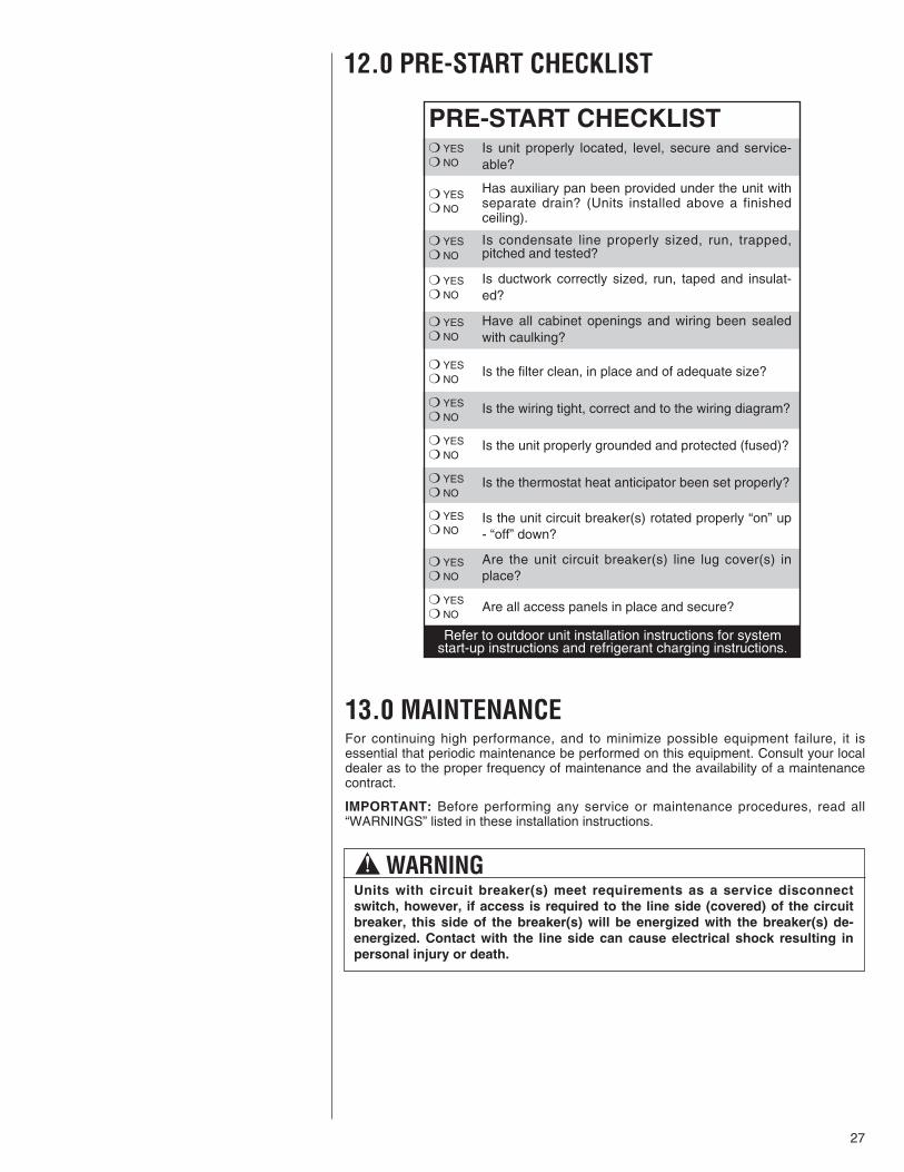
12.0 PRE-START CHECKLIST
! WARNINGUnits with circuit breaker(s) meet requirements as a service disconnectswitch, however, if access is required to the line side (covered) of the circuitbreaker, this side of the breaker(s) will be energized with the breaker(s) de-energized. Contact with the line side can cause electrical shock resulting inpersonal injury or death.
PRE-START CHECKLISTIs unit properly located, level, secure and service-able?
Has auxiliary pan been provided under the unit withseparate drain? (Units installed above a finishedceiling).
Is condensate line properly sized, run, trapped,pitched and tested?
Is ductwork correctly sized, run, taped and insulat-ed?
Have all cabinet openings and wiring been sealedwith caulking?
Is the filter clean, in place and of adequate size?
Is the wiring tight, correct and to the wiring diagram?
Is the unit properly grounded and protected (fused)?
Is the thermostat heat anticipator been set properly?
Is the unit circuit breaker(s) rotated properly “on” up- “off” down?
Are the unit circuit breaker(s) line lug cover(s) inplace?
Are all access panels in place and secure?
❍ YES ❍ NO
❍ YES ❍ NO
❍ YES ❍ NO
❍ YES ❍ NO
❍ YES ❍ NO
❍ YES ❍ NO
❍ YES ❍ NO
❍ YES ❍ NO
❍ YES ❍ NO
❍ YES ❍ NO
❍ YES ❍ NO
❍ YES ❍ NO
Refer to outdoor unit installation instructions for systemstart-up instructions and refrigerant charging instructions.
28
13.1 AIR FILTER (Not Factory Installed)Check the system filter every ninety days or as often as found to be necessary and ifobstructed, clean or replace at once.
IMPORTANT: Do not operate the system without a filter in place.
13.2 INDOOR COIL - DRAIN PAN - DRAIN LINEInspect the indoor coil once each year for cleanliness and clean as necessary. It is nec-essary to remove the filter and check the return air side of the coil for debris.
IMPORTANT: Do not use caustic household drain cleaners, such as bleach, in the con-densate pan or near the indoor coil. Drain cleaners will quickly damage the indoor coil.
13.3 BLOWER MOTOR AND WHEELInspect the blower motor and wheel for cleanliness. With the system air filter in place, itshould be several years before it would become necessary to clean the blower motorand wheel.
• If it becomes necessary to remove the blower assembly from the unit, see instruc-tions on removal and disassembly of motor, blower and heater parts.
• The blower motor and wheel may be cleaned by using a vacuum with a soft brushattachment. Remove grease with a mild solvent such as hot water and detergent. Becareful not to disturb the balance weights (clips) on the blower wheel blades. Do notdrop or bend wheel as balance will be affected.
13.4 LUBRICATIONThe blower motor sleeve bearings are pre-lubricated by the motor manufacturer and donot have oiling ports. Motor should be run for an indefinite period of time without addi-tional lubrication.
13.5 BLOWER ASSEMBLY REMOVAL AND REPLACEMENTRemoving the blower assembly is not required for normal service and maintenance.Removal is necessary for replacement of components such as motor, blower wheel.After extended use, removal of the blower assembly may become necessary for a thor-ough cleaning of the blower motor and wheel.
! WARNINGIf removal of the blower assembly is required, all disconnect switches supply-ing power to the airhandler must be de-energized and locked (if not in sight ofunit) so the field power wires can be safely removed from the blower assem-bly. Failure to do so can cause electrical shock resulting in personal injury ordeath.
CAUTIONIn compliance with recognized codes, it is recommended that an auxiliarydrain pan be installed under all evaporator coils or units containing evaporatorcoils that are located in any area of a structure where damage to the buildingor building contents may occur as a result of an overflow of the coil drain panor a stoppage in the primary condensate drain piping. See accessory sectionin this manual for secondary horizontal drain pan RXBM-ABXX.
29
• Mark field power supply wiring (for replacement) attached to terminal block or circuitbreaker(s) on blower assembly. Remove wiring from terminal block or circuit break-er(s).
• Mark low voltage control wiring (for replacement) where attached to unit control termi-nals on left side of blower housing.
• Remove a screw holding blower assembly to front channel of cabinet and pull blowerassembly from cabinet.
• To replace blower assembly, slide blower assembly into blower deck. Make sureblower assembly engages lances in deck properly. If assembly hangs up, check tomake sure top and bottom are lined up in proper locations.
• Slide blower assembly to back of cabinet and make sure it is completely engaged.
• Replace two screws holding blower assembly to front channel of cabinet. Take carenot to strip screws, just snug into place.
• Replace low voltage control wiring with wire nuts and make sure wiring is to wiringdiagram and a good connection has been made.
• Replace field power wiring to terminal block or circuit breaker(s) on control area ofblower assembly. Make sure wires are replaced as they were, check wiring diagram ifnecessary. Tighten supply power wiring securely to terminals lugs.
• Make sure wiring is within cabinet and will not interfere with access door. Make sureproper separation between low voltage control wiring and field power wiring has beenmaintained.
• Replace blower assembly control access panel before energizing equipment.
13.6 MOTOR REPLACEMENTWith the blower assembly removed, the indoor blower motor can be removed andreplaced using the following procedure:
• Remove motor leads from the motor high and low voltage plugs. Note the lead loca-tions for ease of re-assembly.
• Loosen the set screw holding the blower wheel onto the motor shaft. The shaftextends through the blower hub so that a wrench can be used on the extended shaftto break the shaft loose if necessary. Be careful not to damage the shaft. Use awheel puller on the groove in the hub if necessary.
• Loosen the bolt holding the wire motor band around the motor shell and pull themotor from the motor mount. Note the motor position in the mount for re-assembly.
• To re-assemble, insert the motor shaft through the hub in the blower wheel and orientthe motor to original position.
• For proper motor cooling, it is important that the motor be mounted the same as theoriginal, as far into the blower as practical.
• The dimension from the face of the motor end plate (shaft end) to the first wire on themotor mount band around the shell should be:
DIMENSION TONNAGE CABINET SIZE11/2" 2 21
• With motor held to above position and motor lead plugs oriented to the original posi-tion (the wire connectors on the motor must point straight to the supply air end of theunit and away from the return air [filter] end of the unit). Securely tighten the bolt onthe mount band to the motor shell.
• Turn the motor shaft so that the flat on the shaft is located under blower wheelsetscrew, and the blower wheel is centered in the blower housing with the same dis-tance on each side between the inlet venturi and the outside of the blower wheel.
• Re-assemble the motor wiring (high and low voltage plugs) into the motor.
IMPORTANT: DO NOT FORCE POWER PLUG INTO THE MOTOR CONNECTORBACKWARDS. The A.C. power plug to the motor has locking tabs. It has beenproven that by applying excessive force to the A.C. cable half of the connector it ispossible to force the connector in backwards. It will not seat and “click” properly butwill make connection. If A.C. power is applied with the connector reversed the motorwill be immediately destroyed.
30
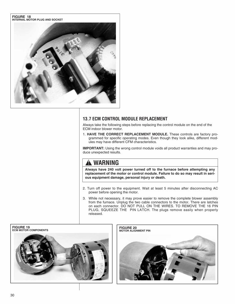
13.7 ECM CONTROL MODULE REPLACEMENTAlways take the following steps before replacing the control module on the end of theECM indoor blower motor.
1. HAVE THE CORRECT REPLACEMENT MODULE. These controls are factory pro-grammed for specific operating modes. Even though they look alike, different mod-ules may have different CFM characteristics.
IMPORTANT: Using the wrong control module voids all product warranties and may pro-duce unexpected results.
2. Turn off power to the equipment. Wait at least 5 minutes after disconnecting ACpower before opening the motor.
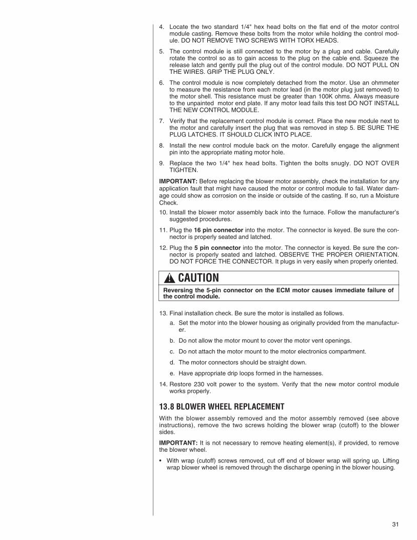
3. While not necessary, it may prove easier to remove the complete blower assemblyfrom the furnace. Unplug the two cable connectors to the motor. There are latcheson each connector. DO NOT PULL ON THE WIRES. TO REMOVE THE 16 PINPLUG, SQUEEZE THE PIN LATCH. The plugs remove easily when properlyreleased.
! WARNINGAlways have 240 volt power turned off to the furnace before attempting anyreplacement of the motor or control module. Failure to do so may result in seri-ous equipment damage, personal injury or death.
FIGURE 18INTERNAL MOTOR PLUG AND SOCKET
FIGURE 19ECM MOTOR COMPONENTS
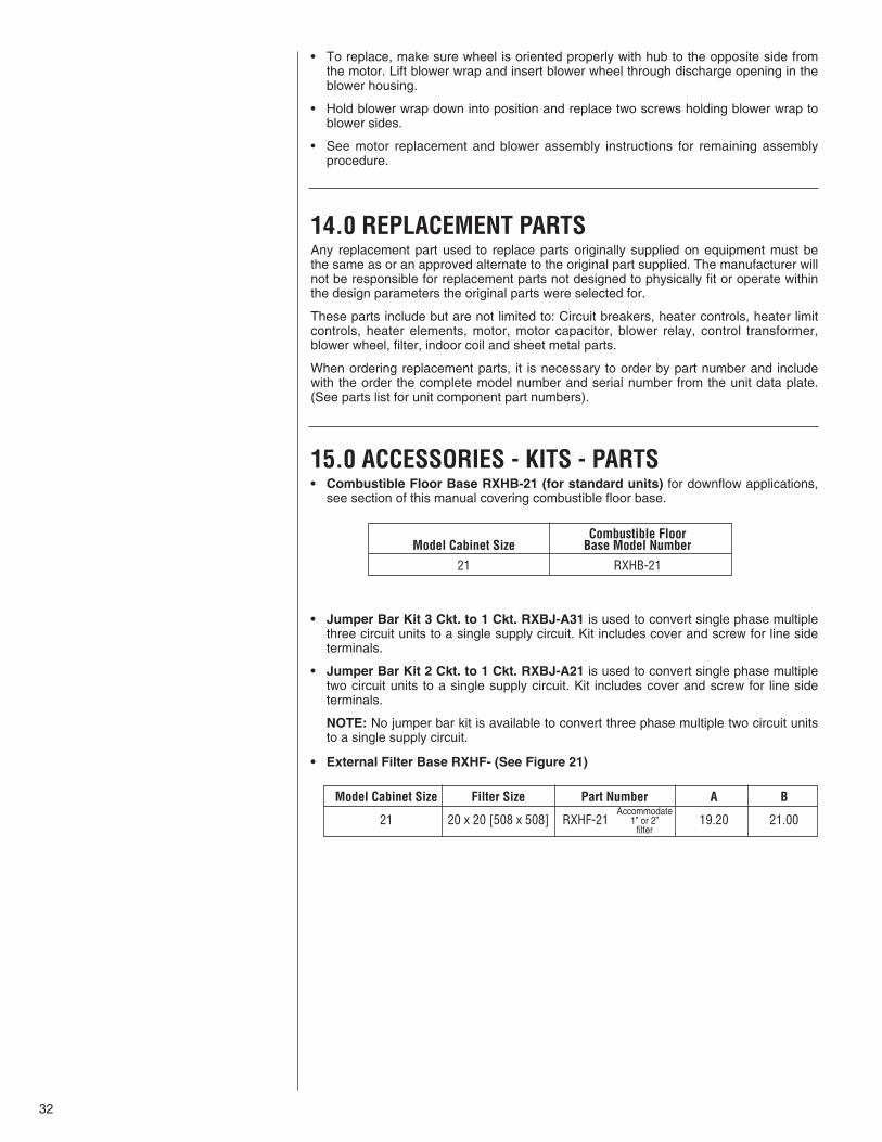
FIGURE 20MOTOR ALIGNMENT PIN
31
4. Locate the two standard 1/4" hex head bolts on the flat end of the motor controlmodule casting. Remove these bolts from the motor while holding the control mod-ule. DO NOT REMOVE TWO SCREWS WITH TORX HEADS.
5. The control module is still connected to the motor by a plug and cable. Carefullyrotate the control so as to gain access to the plug on the cable end. Squeeze therelease latch and gently pull the plug out of the control module. DO NOT PULL ONTHE WIRES. GRIP THE PLUG ONLY.
6. The control module is now completely detached from the motor. Use an ohmmeterto measure the resistance from each motor lead (in the motor plug just removed) tothe motor shell. This resistance must be greater than 100K ohms. Always measureto the unpainted motor end plate. If any motor lead fails this test DO NOT INSTALLTHE NEW CONTROL MODULE.
7. Verify that the replacement control module is correct. Place the new module next tothe motor and carefully insert the plug that was removed in step 5. BE SURE THEPLUG LATCHES. IT SHOULD CLICK INTO PLACE.
8. Install the new control module back on the motor. Carefully engage the alignmentpin into the appropriate mating motor hole.
9. Replace the two 1/4" hex head bolts. Tighten the bolts snugly. DO NOT OVERTIGHTEN.
IMPORTANT: Before replacing the blower motor assembly, check the installation for anyapplication fault that might have caused the motor or control module to fail. Water dam-age could show as corrosion on the inside or outside of the casting. If so, run a MoistureCheck.
10. Install the blower motor assembly back into the furnace. Follow the manufacturer’ssuggested procedures.
11. Plug the 16 pin connector into the motor. The connector is keyed. Be sure the con-nector is properly seated and latched.
12. Plug the 5 pin connector into the motor. The connector is keyed. Be sure the con-nector is properly seated and latched. OBSERVE THE PROPER ORIENTATION.DO NOT FORCE THE CONNECTOR. It plugs in very easily when properly oriented.
13. Final installation check. Be sure the motor is installed as follows.
a. Set the motor into the blower housing as originally provided from the manufactur-er.
b. Do not allow the motor mount to cover the motor vent openings.
c. Do not attach the motor mount to the motor electronics compartment.
d. The motor connectors should be straight down.
e. Have appropriate drip loops formed in the harnesses.
14. Restore 230 volt power to the system. Verify that the new motor control moduleworks properly.
13.8 BLOWER WHEEL REPLACEMENTWith the blower assembly removed and the motor assembly removed (see aboveinstructions), remove the two screws holding the blower wrap (cutoff) to the blowersides.
IMPORTANT: It is not necessary to remove heating element(s), if provided, to removethe blower wheel.
• With wrap (cutoff) screws removed, cut off end of blower wrap will spring up. Liftingwrap blower wheel is removed through the discharge opening in the blower housing.
! CAUTIONReversing the 5-pin connector on the ECM motor causes immediate failure ofthe control module.
32
• To replace, make sure wheel is oriented properly with hub to the opposite side fromthe motor. Lift blower wrap and insert blower wheel through discharge opening in theblower housing.
• Hold blower wrap down into position and replace two screws holding blower wrap toblower sides.
• See motor replacement and blower assembly instructions for remaining assemblyprocedure.
14.0 REPLACEMENT PARTSAny replacement part used to replace parts originally supplied on equipment must bethe same as or an approved alternate to the original part supplied. The manufacturer willnot be responsible for replacement parts not designed to physically fit or operate withinthe design parameters the original parts were selected for.
These parts include but are not limited to: Circuit breakers, heater controls, heater limitcontrols, heater elements, motor, motor capacitor, blower relay, control transformer,blower wheel, filter, indoor coil and sheet metal parts.
When ordering replacement parts, it is necessary to order by part number and includewith the order the complete model number and serial number from the unit data plate.(See parts list for unit component part numbers).
15.0 ACCESSORIES - KITS - PARTS• Combustible Floor Base RXHB-21 (for standard units) for downflow applications,
see section of this manual covering combustible floor base.
• Jumper Bar Kit 3 Ckt. to 1 Ckt. RXBJ-A31 is used to convert single phase multiplethree circuit units to a single supply circuit. Kit includes cover and screw for line sideterminals.
• Jumper Bar Kit 2 Ckt. to 1 Ckt. RXBJ-A21 is used to convert single phase multipletwo circuit units to a single supply circuit. Kit includes cover and screw for line sideterminals.
NOTE: No jumper bar kit is available to convert three phase multiple two circuit unitsto a single supply circuit.
• External Filter Base RXHF- (See Figure 21)
Combustible FloorModel Cabinet Size Base Model Number
21 RXHB-21
Model Cabinet Size Filter Size Part Number A B
21 20 x 20 [508 x 508] RXHF-21 19.20 21.00Accommodate
1” or 2” filter
33
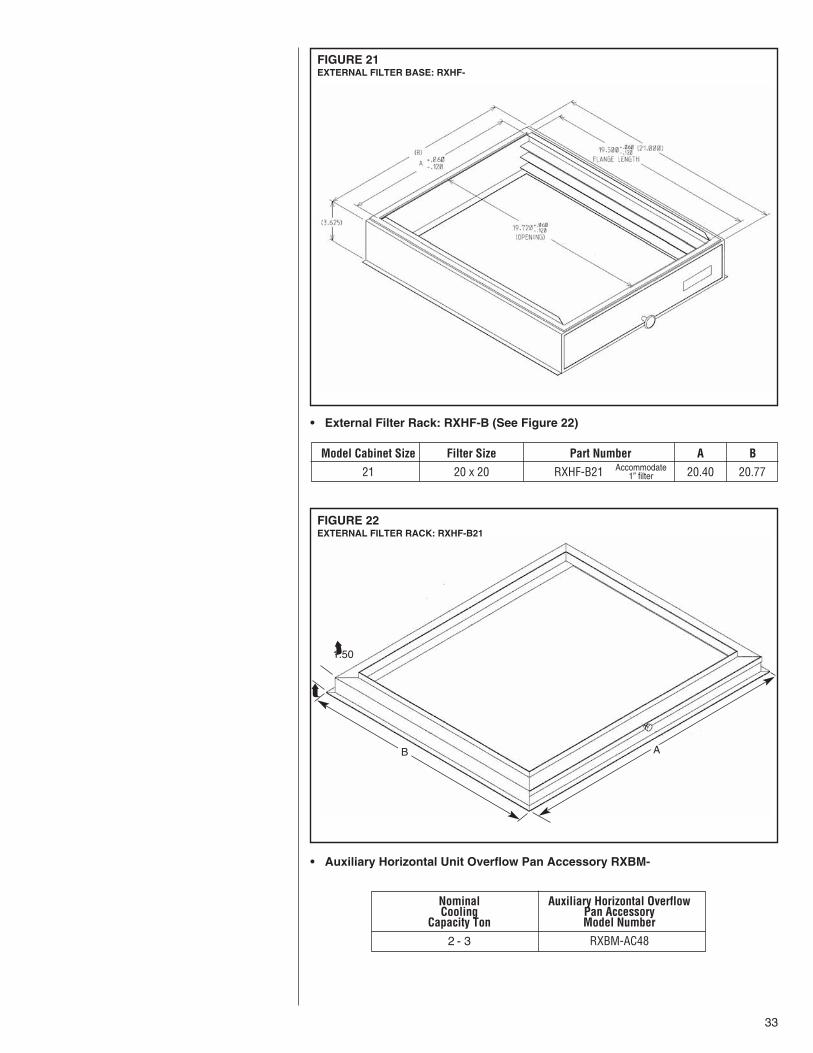
• External Filter Rack: RXHF-B (See Figure 22)
• Auxiliary Horizontal Unit Overflow Pan Accessory RXBM-
FIGURE 22EXTERNAL FILTER RACK: RXHF-B21
B
1.50
A
➦
➦
Model Cabinet Size Filter Size Part Number A B
21 20 x 20 RXHF-B21 20.40 20.77Accommodate1” filter
Nominal Auxiliary Horizontal OverflowCooling Pan Accessory
Capacity Ton Model Number
2 - 3 RXBM-AC48
FIGURE 21EXTERNAL FILTER BASE: RXHF-

34

35

36 CM 0207


![Ruud Ultra Series Two-Stage Air Conditioners equipped with ... · 16.0 UASL- JEC Series Efficiencies up to 18SEER/14 EER Nominal Sizes 2 to 5 Ton [7.03 to 17.6 kW] Cooling Capacities](https://img.pdfslide.net/doc/110x75/6019a4657a222f0ff64096b0/ruud-ultra-series-two-stage-air-conditioners-equipped-with-160-uasl-jec-series.jpg)