Embed Size (px)
Citation preview
Ney VULCAN D - CONTROL
Owner & Operator’s Manual
MODELS: D-130 D-550 D-1750 D-1750 EURO 100V --------------- 9495132 --------------- ---------------
100 – 120V 9495120 9495130 --------------- --------------- 230V 9495121 9495131 9495140 9495141
Table of Contents
DESCRIPTION PAGE Safety ……………………. 2
Technical Data ……………………. 3
Installation Instructions ……………………. 4
General Operation ……………………. 5
Maintenance ……………………. 8
Troubleshooting ……………………. 9
Product Service ……………………. 10
Declaration of Conformity ……………………. 11
Warranty ……………………. Back
2
SAFETY
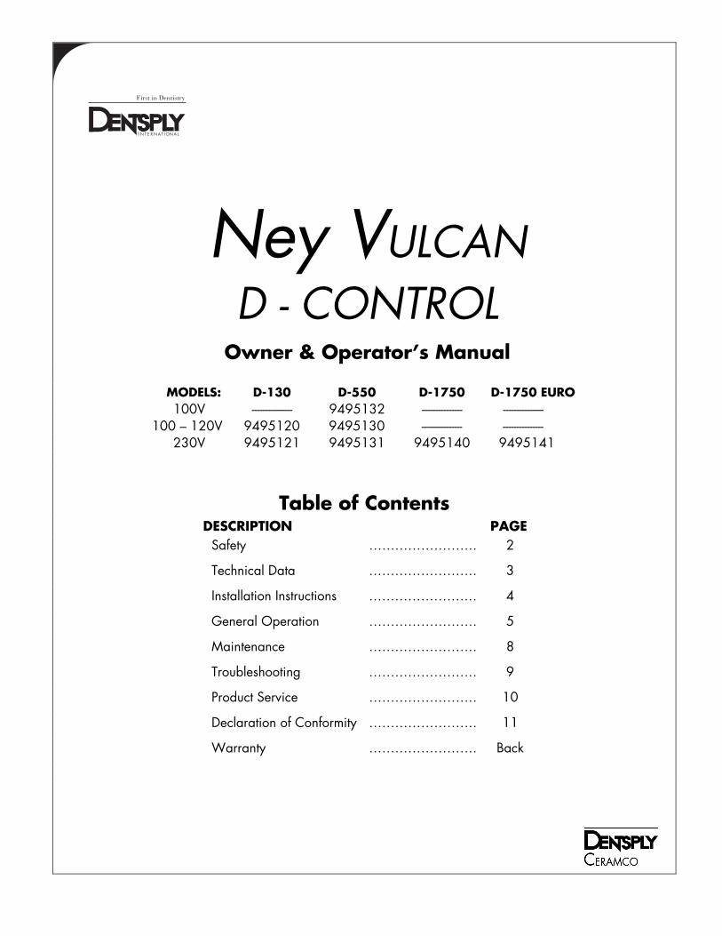
FOR PROFESSIONAL USE ONLY.
Please read these operating instructions carefully before installing or operating this equipment. • Use indoors only. • Never operate the unit in close proximity to combustible materials or place materials on top of the unit. • The unit must be electrically grounded to a three wire electrical outlet or receptacle. The electrical service provided
must be a dedicated line of the proper size according to local electrical codes. • Unit must be placed in a position that allows the power cord to be easily disconnected from the wall or inlet
socket. • Do not attempt to maintain the unit until you have read and understand this operation manual. • Disconnect the line cord before attempting to service the unit. • Do not operate the unit controls with tongs or other tools. • Do not use solvents or liquid cleaners on the control panel. • Do not cover the top of the unit. • If the unit is not operated in the manner as specified in this manual, the protection provided by the unit may be
impaired.
CAUTION: RISK OF DANGER! BURN HAZARD IS PRESENT WHEN DOOR IS OPENED. USE CAUTION AFTER OPENING DOOR.
SURFACES MAY BE HOT!
OSHA AND CALIFORNIA PROPOSITION 65: MUFFLE DUST EXPOSURE In keeping with the policy of DENTSPLY Ceramco to build safe products, comply with all National and State statutes and keep you, the valued customer informed; the services of a Certified Industrial Hygienist firm were employed to test and evaluate the lab operator’s exposure to respirable refractory ceramic fiber (RCF) and crystobalite (a form of crystalline silica) present in the furnace muffle.
The findings of this test revealed that levels of exposure during the normal operation of this equipment, as outlined in the operator’s manual, were far less than the Permissible Exposure Limit set by the Federal Government.
When it becomes necessary to replace the muffle, the person doing this work is recommended to wear a HEPA filter respirator and protective gloves as a precautionary matter.
Seal used muffle in a plastic bag and dispose of in accordance with local, state and Federal regulations.
Because this product and many similar products on the market today contain crystalline silica and ceramic fibers, it is necessary under the statutes of California Proposition 65 that DENTSPLY Ceramco includes the following statement:
“This product contains substance(s) known to the State of California to cause cancer.”
Material Safety Data Sheets for RCF materials supplied upon request.
SYMBOL TABLE
- Alternating current Courant alternatif
I - On (Supply) Marche (alimentation)
O - Off (Supply) Arrêt (alimentation) - Caution, Hot Surface Attention, surface chaude - Protective Conductor Terminal Borne de masse, châssis - Caution, Risk of Danger Attention risque de DANGER
!
!
3
TECHNICAL DATA
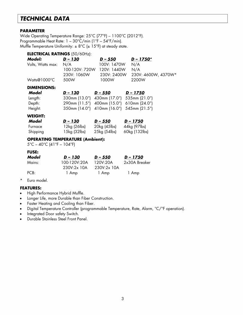
PARAMETER Wide Operating Temperature Range: 25°C (77°F) – 1100°C (2012°F). Programmable Heat Rate: 1 – 30°C/min (1°F – 54°F/min). Muffle Temperature Uniformity: ± 8°C (± 15°F) at steady state.
ELECTRICAL RATINGS (50/60Hz): Model: D – 130 D – 550 D – 1750* Volts, Watts max: N/A 100V: 1470W N/A 100-120V: 720W 120V: 1440W N/A 230V: 1060W 230V: 2400W 230V: 4600W, 4370W* Watts@1000°C 500W 1000W 2200W
DIMENSIONS: Model D – 130 D – 550 D – 1750 Length: 330mm (13.0”) 430mm (17.0”) 535mm (21.0”) Depth: 290mm (11.5”) 400mm (15.0”) 610mm (24.0”) Height: 350mm (14.0”) 410mm (16.0”) 545mm (21.5”)
WEIGHT: Model D – 130 D – 550 D – 1750 Furnace 12kg (26lbs) 20kg (45lbs) 44kg (97lbs) Shipping 15kg (32lbs) 25kg (54lbs) 60kg (132lbs)
OPERATING TEMPERATURE (Ambient): 5°C – 40°C (41°F – 104°F)
FUSE: Model D – 130 D – 550 D – 1750 Mains: 100-120V:20A 120V:20A 2x30A Breaker
230V:2x 10A 230V:2x 10A PCB: 1 Amp 1 Amp 1 Amp
* Euro model.
FEATURES: • High Performance Hybrid Muffle. • Longer Life, more Durable than Fiber Construction. • Faster Heating and Cooling than Fiber. • Digital Temperature Controller (programmable Temperature, Rate, Alarm, °C/°F operation). • Integrated Door safety Switch. • Durable Stainless Steel Front Panel.
4
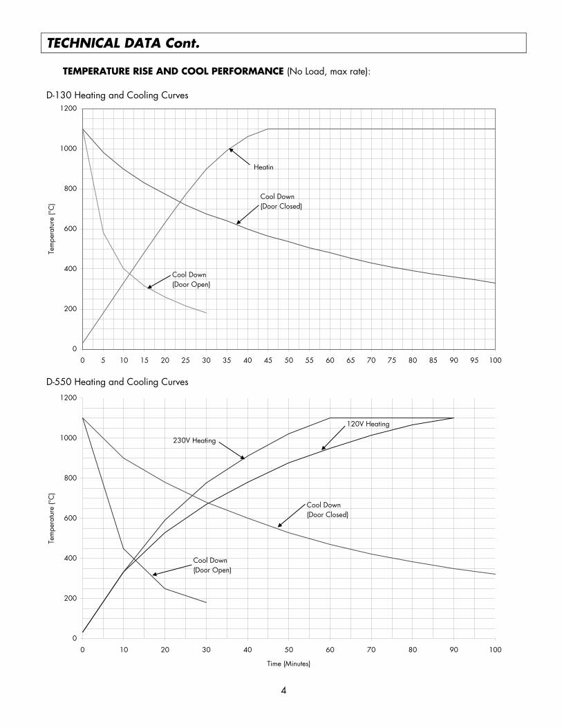
D-550 Heating and Cooling Curves
0
200
400
600
800
1000
1200
0 10 20 30 40 50 60 70 80 90 100
Time (Minutes)
Tem
pera
ture
(°C
)
230V Heating
Cool Down (Door Open)
Cool Down(Door Closed)
120V Heating
D-130 Heating and Cooling Curves
0
200
400
600
800
1000
1200
0 5 10 15 20 25 30 35 40 45 50 55 60 65 70 75 80 85 90 95 100
Time (Minutes)
Tem
pera
ture
(°C
)
Heatin
Cool Down(Door Closed)
Cool Down(Door Open)
TECHNICAL DATA Cont. TEMPERATURE RISE AND COOL PERFORMANCE (No Load, max rate):
D-130 Heating and Cooling Curves D-550 Heating and Cooling Curves
5
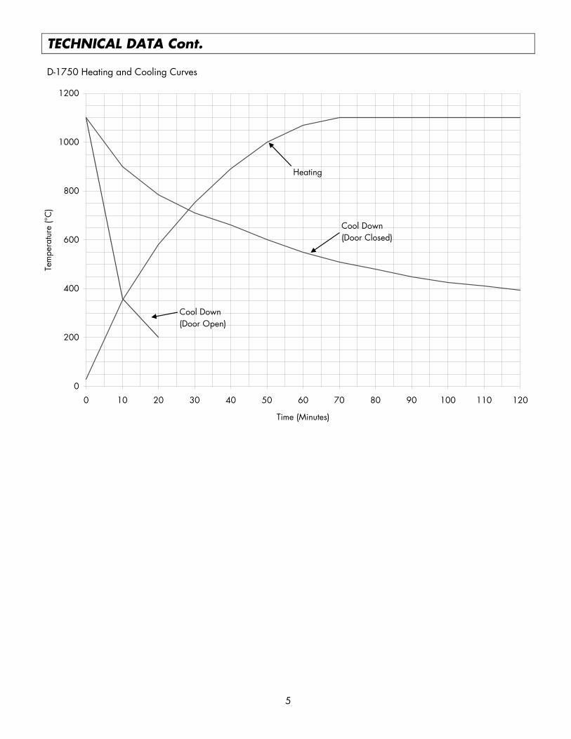
D-1750 Heating and Cooling Curves
0
200
400
600
800
1000
1200
0 10 20 30 40 50 60 70 80 90 100 110 120
Time (Minutes)
Tem
pera
ture
(°C
)
Cool Down(Door Closed)
Heating
Cool Down(Door Open)
TECHNICAL DATA Cont. D-1750 Heating and Cooling Curves
6
INSTALLATION INSTRUCTIONS
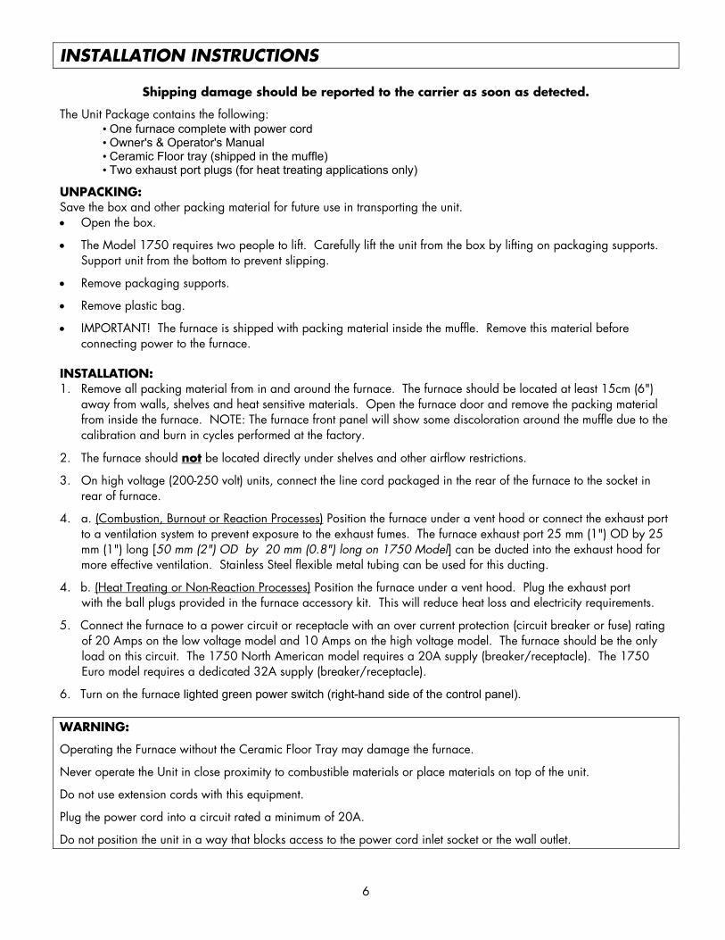
Shipping damage should be reported to the carrier as soon as detected.
The Unit Package contains the following: • One furnace complete with power cord • Owner's & Operator's Manual • Ceramic Floor tray (shipped in the muffle) • Two exhaust port plugs (for heat treating applications only)
UNPACKING: Save the box and other packing material for future use in transporting the unit. • Open the box.
• The Model 1750 requires two people to lift. Carefully lift the unit from the box by lifting on packaging supports. Support unit from the bottom to prevent slipping.
• Remove packaging supports.
• Remove plastic bag.
• IMPORTANT! The furnace is shipped with packing material inside the muffle. Remove this material before connecting power to the furnace.
INSTALLATION: 1. Remove all packing material from in and around the furnace. The furnace should be located at least 15cm (6")
away from walls, shelves and heat sensitive materials. Open the furnace door and remove the packing material from inside the furnace. NOTE: The furnace front panel will show some discoloration around the muffle due to the calibration and burn in cycles performed at the factory.
2. The furnace should not be located directly under shelves and other airflow restrictions.
3. On high voltage (200-250 volt) units, connect the line cord packaged in the rear of the furnace to the socket in rear of furnace.
4. a. (Combustion, Burnout or Reaction Processes) Position the furnace under a vent hood or connect the exhaust port to a ventilation system to prevent exposure to the exhaust fumes. The furnace exhaust port 25 mm (1") OD by 25 mm (1") long [50 mm (2") OD by 20 mm (0.8") long on 1750 Model] can be ducted into the exhaust hood for more effective ventilation. Stainless Steel flexible metal tubing can be used for this ducting.
4. b. (Heat Treating or Non-Reaction Processes) Position the furnace under a vent hood. Plug the exhaust port with the ball plugs provided in the furnace accessory kit. This will reduce heat loss and electricity requirements.
5. Connect the furnace to a power circuit or receptacle with an over current protection (circuit breaker or fuse) rating of 20 Amps on the low voltage model and 10 Amps on the high voltage model. The furnace should be the only load on this circuit. The 1750 North American model requires a 20A supply (breaker/receptacle). The 1750 Euro model requires a dedicated 32A supply (breaker/receptacle).
6. Turn on the furnace lighted green power switch (right-hand side of the control panel). WARNING:
Operating the Furnace without the Ceramic Floor Tray may damage the furnace.
Never operate the Unit in close proximity to combustible materials or place materials on top of the unit.
Do not use extension cords with this equipment.
Plug the power cord into a circuit rated a minimum of 20A.
Do not position the unit in a way that blocks access to the power cord inlet socket or the wall outlet.
7
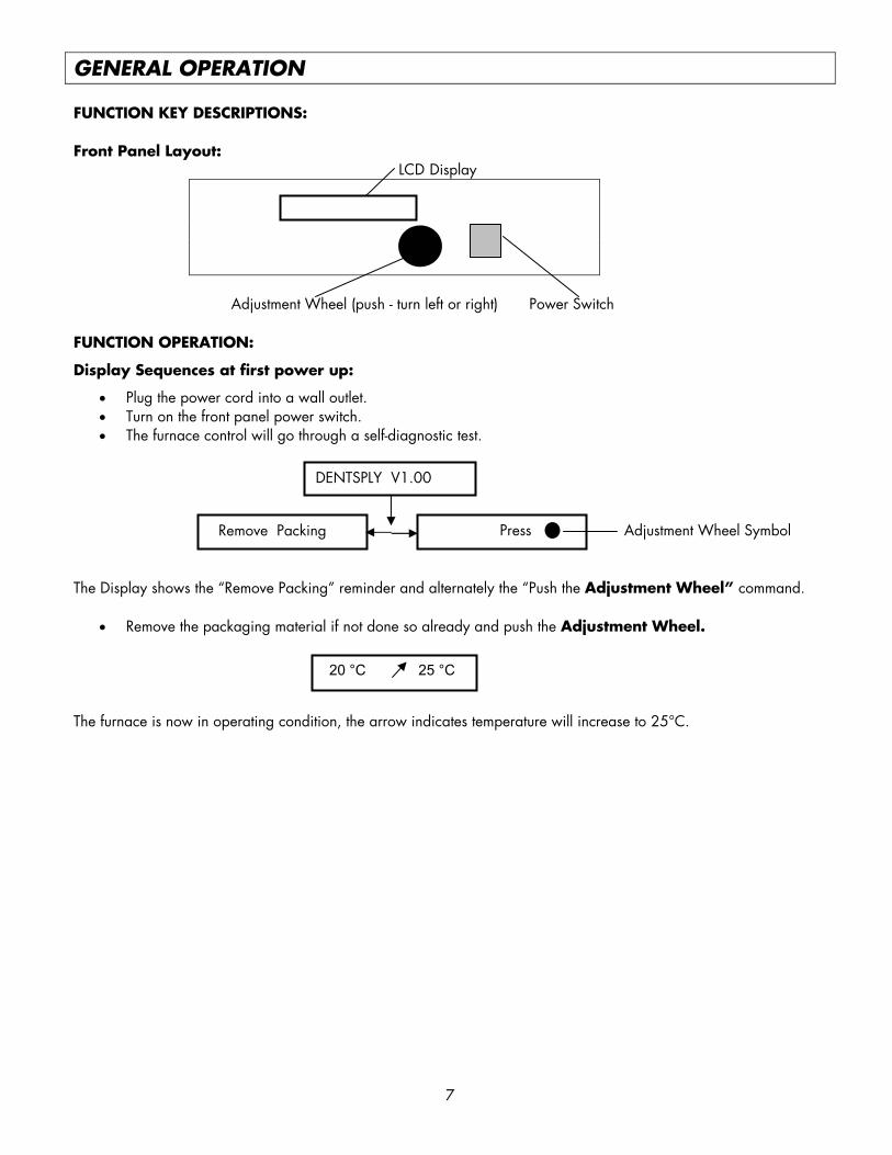
GENERAL OPERATION FUNCTION KEY DESCRIPTIONS: Front Panel Layout: LCD Display
Adjustment Wheel (push - turn left or right) Power Switch
FUNCTION OPERATION:
Display Sequences at first power up:
• Plug the power cord into a wall outlet. • Turn on the front panel power switch. • The furnace control will go through a self-diagnostic test.
Adjustment Wheel Symbol The Display shows the “Remove Packing” reminder and alternately the “Push the Adjustment Wheel” command.
• Remove the packaging material if not done so already and push the Adjustment Wheel. The furnace is now in operating condition, the arrow indicates temperature will increase to 25°C.
DENTSPLY V1.00
Remove Packing Press
20 °C 25 °C
8
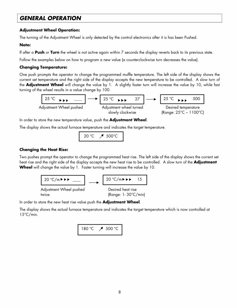
GENERAL OPERATION Adjustment Wheel Operation:
The turning of the Adjustment Wheel is only detected by the control electronics after it is has been Pushed.
Note:
If after a Push or Turn the wheel is not active again within 7 seconds the display reverts back to its previous state.
Follow the examples below on how to program a new value (a counterclockwise turn decreases the value).
Changing Temperature:
One push prompts the operator to change the programmed muffle temperature. The left side of the display shows the current set temperature and the right side of the display accepts the new temperature to be controlled. A slow turn of the Adjustment Wheel will change the value by 1. A slightly faster turn will increase the value by 10, while fast turning of the wheel results in a value change by 100.
Adjustment Wheel pushed Adjustment wheel turned Desired temperature
slowly clockwise (Range: 25°C – 1100°C)
In order to store the new temperature value, push the Adjustment Wheel.
The display shows the actual furnace temperature and indicates the target temperature.
Changing the Heat Rise:
Two pushes prompt the operator to change the programmed heat rise. The left side of the display shows the current set heat rise and the right side of the display accepts the new heat rise to be controlled. A slow turn of the Adjustment Wheel will change the value by 1. Faster turning will increase the value by 10.
Adjustment Wheel pushed Desired heat rise twice. (Range: 1- 30°C/min)
In order to store the new heat rise value push the Adjustment Wheel.
The display shows the actual furnace temperature and indicates the target temperature which is now controlled at 15°C/min.
25 °C ____
20 °C/m ____
25 °C 27 25 °C 500
20 °C 500°C
20 °C/m 15
180 °C 500 °C
9
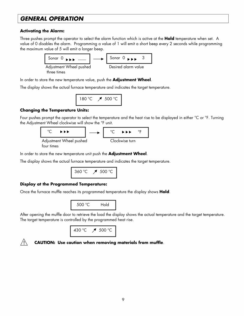
GENERAL OPERATION Activating the Alarm:
Three pushes prompt the operator to select the alarm function which is active at the Hold temperature when set. A value of 0 disables the alarm. Programming a value of 1 will emit a short beep every 2 seconds while programming the maximum value of 5 will emit a longer beep.
Adjustment Wheel pushed Desired alarm value three times
In order to store the new temperature value, push the Adjustment Wheel.
The display shows the actual furnace temperature and indicates the target temperature.
Changing the Temperature Units:
Four pushes prompt the operator to select the temperature and the heat rise to be displayed in either °C or °F. Turning the Adjustment Wheel clockwise will show the °F unit.
Adjustment Wheel pushed Clockwise turn four times
In order to store the new temperature unit push the Adjustment Wheel.
The display shows the actual furnace temperature and indicates the target temperature.
Display at the Programmed Temperature:
Once the furnace muffle reaches its programmed temperature the display shows Hold.
After opening the muffle door to retrieve the load the display shows the actual temperature and the target temperature. The target temperature is controlled by the programmed heat rise.
CAUTION: Use caution when removing materials from muffle.
500 °C Hold
Sonar 0 ____
°C
Sonar 0 3
180 °C 500 °C
°C °F
360 °C 500 °C
430 °C 500 °C
!
10
MAINTENANCE/ERROR MESSAGES WARNING:
This equipment contains dangerous voltages. Maintenance and repair work should only be performed by an authorized service technician of DENTSPLY Ceramco.
To keep the equipment in good working order you should follow the guidelines below.
• Examine the equipment regularly for mechanical damage.
• Do not use solvents or liquid cleaners on the control panel.
TEMPERATURE CALIBRATION:
Every VULCAN furnace is calibrated in the factory at 1000°C. Under normal use the furnace should not require calibration. The electronics used in the VULCAN furnaces are very stable and will have minimal drifts over the live of the furnace. Thermocouple replacement could be a potential requirement for calibration if high accuracy is required.
For example:
A furnace is operating at a stable temperature and a separate thermocouple is inserted in the furnace and a digital thermometer measures the muffle temperature. The display shows 875°C which is the programmed temperature but the digital thermometer reads 868°C. Turn the trimmer potentiometer, RP3, which is located above the thermocouple connector on the “D” controller board clockwise until the display reads the same temperature as the meter. Allow the furnace temperature to stabilize for 5 – 10 minutes before making further adjustments.
CLEANING:
• Clean the unit as needed.
• Vacuum dust and dirt from the furnace rather than blow. This will minimize the amount of air born dust particles.
• Clean exterior surfaces with a soft, damp cloth using a mild detergent and water.
• DO NOT IMMERSE IN WATER!
11
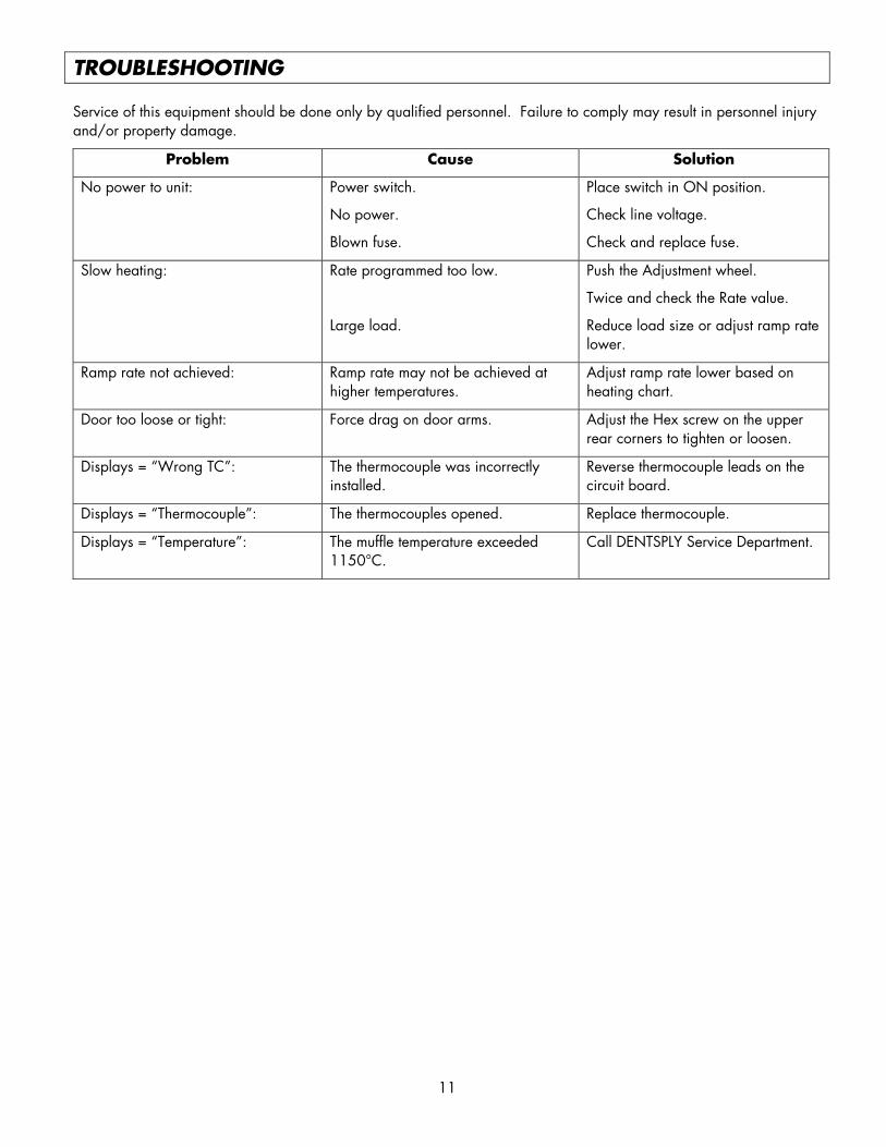
TROUBLESHOOTING Service of this equipment should be done only by qualified personnel. Failure to comply may result in personnel injury and/or property damage.
Problem Cause Solution
No power to unit: Power switch.
No power.
Blown fuse.
Place switch in ON position.
Check line voltage.
Check and replace fuse.
Slow heating: Rate programmed too low.
Large load.
Push the Adjustment wheel.
Twice and check the Rate value.
Reduce load size or adjust ramp rate lower.
Ramp rate not achieved: Ramp rate may not be achieved at higher temperatures.
Adjust ramp rate lower based on heating chart.
Door too loose or tight: Force drag on door arms. Adjust the Hex screw on the upper rear corners to tighten or loosen.
Displays = “Wrong TC”: The thermocouple was incorrectly installed.
Reverse thermocouple leads on the circuit board.
Displays = “Thermocouple”: The thermocouples opened. Replace thermocouple.
Displays = “Temperature”: The muffle temperature exceeded 1150°C.
Call DENTSPLY Service Department.
12
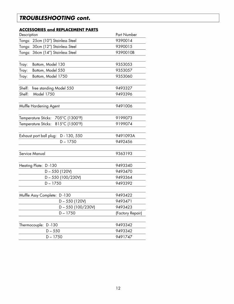
TROUBLESHOOTING cont. ACCESSORIES and REPLACEMENT PARTS Description Part Number Tongs: 25cm (10”) Stainless Steel 9390014 Tongs: 30cm (12”) Stainless Steel 9390015 Tongs: 36cm (14”) Stainless Steel 9390010B Tray: Bottom, Model 130 9353053 Tray: Bottom, Model 550 9353057 Tray: Bottom, Model 1750 9353060 Shelf: free standing Model 550 9493327 Shelf: Model 1750 9493396 Muffle Hardening Agent 9491006 Temperature Sticks: 705°C (1300°F) 9199073 Temperature Sticks: 815°C (1500°F) 9199074 Exhaust port ball plug: D - 130, 550 9491093A D – 1750 9492456 Service Manual 9363193 Heating Plate: D -130 9493340 D – 550 (120V) 9493470 D – 550 (100/230V) 9493364 D – 1750 9493392 Muffle Assy Complete: D -130 9493422 D – 550 (120V) 9493471 D – 550 (100/230V) 9493423 D – 1750 (Factory Repair) Thermocouple: D -130 9493342 D – 550 9493342 D – 1750 9491747
13
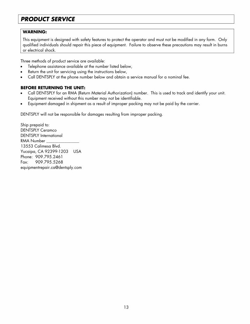
PRODUCT SERVICE WARNING:
This equipment is designed with safety features to protect the operator and must not be modified in any form. Only qualified individuals should repair this piece of equipment. Failure to observe these precautions may result in burns or electrical shock.
Three methods of product service are available: • Telephone assistance available at the number listed below, • Return the unit for servicing using the instructions below, • Call DENTSPLY at the phone number below and obtain a service manual for a nominal fee. BEFORE RETURNING THE UNIT: • Call DENTSPLY for an RMA (Return Material Authorization) number. This is used to track and identify your unit.
Equipment received without this number may not be identifiable. • Equipment damaged in shipment as a result of improper packing may not be paid by the carrier. DENTSPLY will not be responsible for damages resulting from improper packing. Ship prepaid to: DENTSPLY Ceramco DENTSPLY International RMA Number ________________ 13553 Calimesa Blvd. Yucaipa, CA 92399-1203 USA Phone: 909.795.2461 Fax: 909.795.5268 [email protected]
14
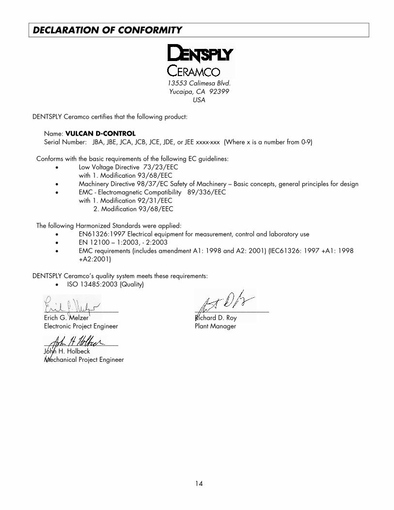
DECLARATION OF CONFORMITY
13553 Calimesa Blvd. Yucaipa, CA 92399
USA DENTSPLY Ceramco certifies that the following product:
Name: VULCAN D-CONTROL Serial Number: JBA, JBE, JCA, JCB, JCE, JDE, or JEE xxxx-xxx (Where x is a number from 0-9)
Conforms with the basic requirements of the following EC guidelines:
• Low Voltage Directive 73/23/EEC with 1. Modification 93/68/EEC
• Machinery Directive 98/37/EC Safety of Machinery – Basic concepts, general principles for design • EMC - Electromagnetic Compatibility 89/336/EEC
with 1. Modification 92/31/EEC 2. Modification 93/68/EEC
The following Harmonized Standards were applied:
• EN61326:1997 Electrical equipment for measurement, control and laboratory use • EN 12100 – 1:2003, - 2:2003 • EMC requirements (includes amendment A1: 1998 and A2: 2001) (IEC61326: 1997 +A1: 1998
+A2:2001) DENTSPLY Ceramco’s quality system meets these requirements:
• ISO 13485:2003 (Quality)
_______________________ _______________________ Erich G. Melzer Richard D. Roy Electronic Project Engineer Plant Manager
_______________________ John H. Holbeck Mechanical Project Engineer

15
Page Intentionally Left Blank
16
WARRANTY WARRANTY: Except with respect to those components parts and uses which are hereinafter described, DENTSPLY Ceramco warrants this furnace to be free from defects in material and workmanship for a period of two years from the date of sale. DENTSPLY Ceramco ’s liability under this warranty is limited solely to repairing or, at DENTSPLY Ceramco ’s option, replacing those products included within the warranty which are returned to DENTSPLY Ceramco within the applicable warranty period (with shipping charges prepaid), and which are determined by DENTSPLY Ceramco to be defective. This warranty shall not apply to any product which has been subject to misuse; negligence; or accident; or misapplied; or modified; or repaired by unauthorized persons; or improperly installed. INSPECTION: Buyer shall inspect the product upon receipt. The buyer shall notify DENTSPLY Ceramco in writing of any claims of defects in material and workmanship within thirty days after the buyer discovers or should have discovered the facts upon which such a claim is based. Failure of the buyer to give written notice of such a claim within this time period shall be deemed to be a waiver of such claim. DISCLAIMER: The provisions here-in stated DENTSPLY Ceramco sole obligation and exclude all other remedies or warranties, expressed or implied, including those related to MERCHANTABILITY and FITNESS FOR A PARTICULAR PURPOSE. LIMITATION OF LIABILITY: Under no circumstances shall DENTSPLY Ceramco be liable to the buyer for any incidental, consequential or special damages, losses or expenses. LIMITATION OF ACTIONS: The buyer must initiate any action with respect to claims under the warranty described in the first paragraph within one year after the cause of action has accrued.
Corporate and Sales Office: Product Service Office: DENTSPLY Ceramco DENTSPLY Ceramco DENTSPLY International DENTSPLY International 570 West College Avenue 13553 Calimesa Blvd. York, PA 17404-0872 USA Yucaipa, CA 92399 USA PH: 800.847.0100 PH: 909.795.2461 FAX: 800.735.1101 FAX: 909.795.5268 [email protected]
EU-Rep., DeguDent GmbH DENTSPLY CanadaPostfach 1364, 63403 Hanau 161 Vinyl Ct. Germany Woodbridge, Ontario L4L 4A3 Tel. +49/6181/59-50 905.851.5374
PC 93631920605 rev. A
DENTSPLY CeramcoAll Rights Reserved
Printed in USA