Embed Size (px)
Citation preview
User Guide for
Profibus Protocol on Elektronikon ComBox-P
Name Mark IV : User Guide Serc. Class
1102 K/1
Detail User Guide Profibus Protocol on Elektronikon ComBox-P
PC Owner
Edition Modified from Print date AII 06 Family Written by Compare Replaces Designation
CTE-PVT Design checked. Production checked. Approved Date
9820 3582 03
Atlas Copco Airpower NV
Profibus Protocol for ComBox-P
File :9820 3582 03 User Guide MKIV Profibus Edition 06 Project : - Page 1
Document Information
Edition Date Description Author
0 Draft update CTE
01 15/09/2003 Added Turbo and PetPack CTE-PDJ
Analogue Outputs (Only for Turbo)
02 28/09/2004 Added ES800 ,ESMillennium CTE-PDJ
03 06/07/2005 Changed AV4000 to ZH CTE-PDJ
04 29/08/2005 Added special Alarms CTE-PDJ
05 21/12/2006 Turbo commands deleted, Turbo external setpoint deleted , Turbo status
changed
CTE-PDJ
06 11/05/2007 Address in HEX
Status BD AIF dryer changed
Status BD AII dryer added
ES 6 added
ES 130 added
MCC Reset Command added
Digital Inputs added from 21 to 33
CTE-PDJ
Atlas Copco Airpower NV
Profibus Protocol for ComBox-P
File :9820 3582 03 User Guide MKIV Profibus Edition 06 Project : - Page 2
Table of Contents
User Guide for................................................................................................................................................................................0 Profibus Protocol on Elektronikon ComBox-P ..............................................................................................................................0 Table of Contents ...........................................................................................................................................................................2 1 Preface....................................................................................................................................................................................4 2 The Physical set-up ................................................................................................................................................................4
2.1 Profibus & the Network..................................................................................................................................................4 2.2 The Module (Combox-P) ...............................................................................................................................................5 2.3 LED’s .............................................................................................................................................................................6 2.4 Connector lay-out ...........................................................................................................................................................7
2.4.1 Power Supply .........................................................................................................................................................7 2.4.2 LAN connector .......................................................................................................................................................7 2.4.3 Profibus connection................................................................................................................................................7
Pin Assignment Profibbus ..............................................................................................................................................7 3 Basic Protocol ........................................................................................................................................................................8 4 Profile definition ....................................................................................................................................................................8
4.1 Master – Slave concept...................................................................................................................................................8 4.2 Buffer structure...............................................................................................................................................................8 4.3 Header ............................................................................................................................................................................9
4.3.1 Master to Slave .......................................................................................................................................................9 4.3.2 Slave to Master .......................................................................................................................................................9
4.4 Data Record..................................................................................................................................................................11 4.4.1 Node Address .......................................................................................................................................................11 4.4.2 Profibus Parameter ID for Data Reading..............................................................................................................12
4.4.2.1 Compressor connection ....................................................................................................................................12 4.4.2.2 Detailed General Compressor Condition..........................................................................................................13
4.4.2.2.1 C.C.M. .......................................................................................................................................................14 4.4.2.2.2 Status for Fixed Speed , AQ Fixed Speed , ES002 ....................................................................................15 4.4.2.2.3 Status for MCC..........................................................................................................................................15 4.4.2.2.4 Status for VSD , AQ VSD , PET VSD Booster , ZB VSD.......................................................................16 4.4.2.2.5 Status for ZH Turbo...................................................................................................................................16 4.4.2.2.6 Status for SF (Multi) ..................................................................................................................................17 4.4.2.2.7 Status for PET Fixed Speed .......................................................................................................................17 4.4.2.2.8 Status for BD Dryer (Stand alone) AIF .....................................................................................................18 4.4.2.2.9 Status for BD Dryer (Stand alone) AII ......................................................................................................19 4.4.2.2.10 Status for CD Dryer (Stand alone)..........................................................................................................20 4.4.2.2.11 Status for FD-Fixed Speed & FD-VSD Dryer (Stand alone)...................................................................20 4.4.2.2.12 Status for MD-Fixed Speed Dryer (Stand alone).....................................................................................20
4.4.3 Inputs & Outputs ..................................................................................................................................................21 4.4.3.1 Analogue Inputs – Sensors & Calculated .........................................................................................................21 4.4.3.2 ParameterID......................................................................................................................................................21
4.4.3.2.1 Sensor Inputs .............................................................................................................................................21 4.4.3.2.2 Calculated (virtual) Inputs ........................................................................................................................21
4.4.3.3 “Status” register Interpretation .........................................................................................................................22 4.4.3.4 “Value” register Interpretation .........................................................................................................................22
4.4.3.4.1 Pressure Input ............................................................................................................................................22 4.4.3.4.2 Temperature Input .....................................................................................................................................22 4.4.3.4.3 Vibration Input...........................................................................................................................................22 4.4.3.4.4 Level Input.................................................................................................................................................22 4.4.3.4.5 Conductivity Input .....................................................................................................................................22 4.4.3.4.6 SPM Input..................................................................................................................................................22 4.4.3.4.7 Current Input..............................................................................................................................................23 4.4.3.4.8 Speed Input ................................................................................................................................................23
4.4.3.5 Special Alarms..................................................................................................................................................24 4.4.3.6 Digital (Voltage free contacts) Inputs...............................................................................................................25 4.4.3.7 “Status” register Interpretation .........................................................................................................................25 4.4.3.8 “Value” register Interpretation .........................................................................................................................25 4.4.3.9 Analogue Outputs (Only for Turbo) .................................................................................................................26 4.4.3.10 Registers .......................................................................................................................................................26
Atlas Copco Airpower NV
Profibus Protocol for ComBox-P
File :9820 3582 03 User Guide MKIV Profibus Edition 06 Project : - Page 3
4.4.4 Counters ...............................................................................................................................................................27 4.4.4.1 Compressor Counters .......................................................................................................................................27 4.4.4.2 Multi Compressor Controller Counters ............................................................................................................29 4.4.4.3 ES 6 ..................................................................................................................................................................29
4.4.5 Special ..................................................................................................................................................................30 4.4.5.1 VSD motor data................................................................................................................................................30
4.4.6 ES 8 Data Readout................................................................................................................................................31 4.4.6.1 Analogue Inputs................................................................................................................................................31 4.4.6.2 Digital Inputs ....................................................................................................................................................32 4.4.6.3 Digital Outputs .................................................................................................................................................33 4.4.6.4 ES 8 System Data .............................................................................................................................................34
4.4.7 ES 130 Data Readout............................................................................................................................................35 4.4.7.1 Analogue Inputs................................................................................................................................................35 4.4.7.2 Digital Inputs (Not Used) .................................................................................................................................35 4.4.7.3 Digital Outputs (Not Used)...............................................................................................................................36 4.4.7.4 ES 130 Status Data ...........................................................................................................................................37
4.4.8 ES 6 Data Readout................................................................................................................................................38 4.4.8.1 System Data......................................................................................................................................................38
4.5 Profibus parameters for change ....................................................................................................................................39 4.5.1 Load/Unload Pressure Band change.....................................................................................................................39 4.5.2 VSD Setpoint change ...........................................................................................................................................39 4.5.3 MCC Pressure Band change .................................................................................................................................40 4.5.4 ES 6 Pressure Band change ..................................................................................................................................40 4.5.5 PET L/U Regulation Band Change ......................................................................................................................41 4.5.6 ZH Turbo Regulation Setpoint and Band Change ................................................................................................42 4.5.7 ES 130 SPS..........................................................................................................................................................43 4.5.8 ES 130 Isolate/Integrate Compressor ...................................................................................................................44
4.6 Profibus parameters for remote control ........................................................................................................................45 4.6.1 Control Commands...............................................................................................................................................45
4.6.1.1 Compressor Control Mode Selection................................................................................................................45 4.6.1.2 Compressor Commands....................................................................................................................................47
4.6.2 VSD – external setpoint/speed control .................................................................................................................49 4.6.3 Reset Initial Settings (Analogue , Digital , Counter Inputs) .................................................................................49
4.7 Error Code for Data Record .........................................................................................................................................50 5 Profibus examples ................................................................................................................................................................51
5.1 Setup.............................................................................................................................................................................51 5.2 Header Byte for Data Read-out ....................................................................................................................................51 5.3 Header Byte for Commands or Reprogramming..........................................................................................................51 5.4 Example Of Data Readout...........................................................................................................................................52 5.5 Example Of Command ................................................................................................................................................52 5.6 Example Of Reprogramming ......................................................................................................................................52 5.7 Example Data Error Code ............................................................................................................................................52 5.8 Special Remarks ...........................................................................................................................................................53
6 GSD file example .................................................................................................................................................................54 6.1 Changing GSD File ......................................................................................................................................................55
6.1.1 1 Data Record .....................................................................................................................................................55 6.1.2 2 Data Records....................................................................................................................................................55 6.1.3 4 Data Records....................................................................................................................................................55 6.1.4 8 Data Records....................................................................................................................................................55
6.2 Configuration Example ................................................................................................................................................56
Atlas Copco Airpower NV
Profibus Protocol for ComBox-P
File :9820 3582 03 User Guide MKIV Profibus Edition 06 Project : - Page 4
1 Preface
This document describes Atlas Copco’s Elektronikon MkIV Profibus Profile that is used by the ComBox-P communication
processor.
2 The Physical set-up
2.1 Profibus & the Network
In the Elektronikon MkIV system all compressors in an installation can be connected by a data and/or control network. This is
done according the Compressor Network Cabling Instruction (9820 3585 00). This instruction explains what connectors and
cables should be used to interconnect the different compressors/controllers in the network. Basically this is a CAN-based local
network.
In order to setup a profibus connection to one or several of the compressors in this network, a special module as to be inserted
in this network.
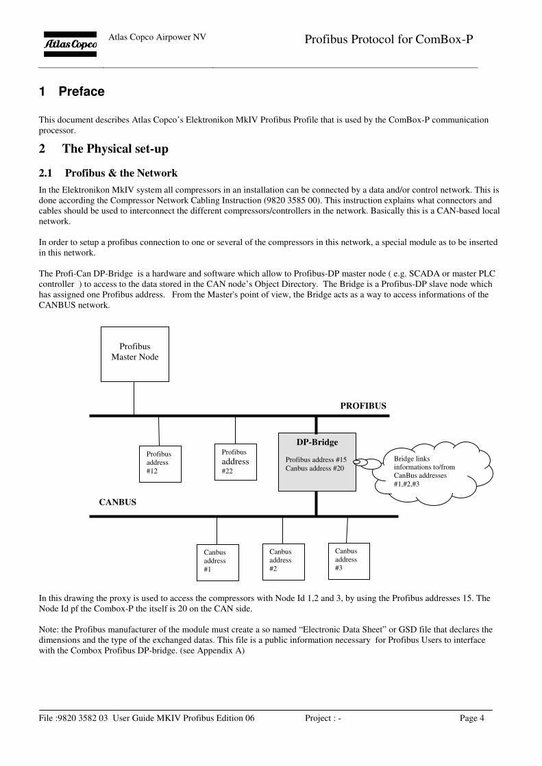
The Profi-Can DP-Bridge is a hardware and software which allow to Profibus-DP master node ( e.g. SCADA or master PLC
controller ) to access to the data stored in the CAN node’s Object Directory. The Bridge is a Profibus-DP slave node which
has assigned one Profibus address. From the Master's point of view, the Bridge acts as a way to access informations of the
CANBUS network.
In this drawing the proxy is used to access the compressors with Node Id 1,2 and 3, by using the Profibus addresses 15. The
Node Id pf the Combox-P the itself is 20 on the CAN side.
Note: the Profibus manufacturer of the module must create a so named “Electronic Data Sheet” or GSD file that declares the
dimensions and the type of the exchanged datas. This file is a public information necessary for Profibus Users to interface
with the Combox Profibus DP-bridge. (see Appendix A)
Profibus
Master Node
Profibus
address
#12
Profibus
address #22
DP-Bridge
Profibus address #15
Canbus address #20
Canbus
address
#1
Canbus
address
#2
Canbus
address
#3
PROFIBUS
CANBUS
Bridge links
informations to/from
CanBus addresses
#1,#2,#3
Atlas Copco Airpower NV
Profibus Protocol for ComBox-P
File :9820 3582 03 User Guide MKIV Profibus Edition 06 Project : - Page 5
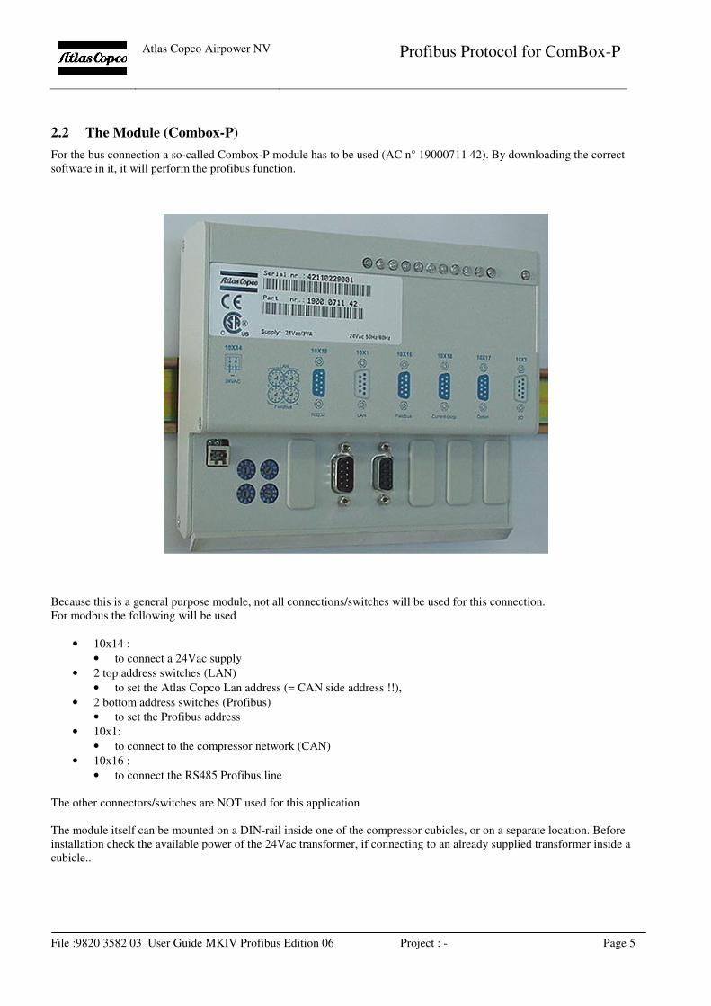
2.2 The Module (Combox-P)
For the bus connection a so-called Combox-P module has to be used (AC n° 19000711 42). By downloading the correct
software in it, it will perform the profibus function.
Because this is a general purpose module, not all connections/switches will be used for this connection.
For modbus the following will be used
• 10x14 :
• to connect a 24Vac supply
• 2 top address switches (LAN)
• to set the Atlas Copco Lan address (= CAN side address !!),
• 2 bottom address switches (Profibus)
• to set the Profibus address
• 10x1:
• to connect to the compressor network (CAN)
• 10x16 :
• to connect the RS485 Profibus line
The other connectors/switches are NOT used for this application
The module itself can be mounted on a DIN-rail inside one of the compressor cubicles, or on a separate location. Before
installation check the available power of the 24Vac transformer, if connecting to an already supplied transformer inside a
cubicle..
Atlas Copco Airpower NV
Profibus Protocol for ComBox-P
File :9820 3582 03 User Guide MKIV Profibus Edition 06 Project : - Page 6
2.3 LED’s
The module also has a number of LED’s on type. They are used as follows :
System LED (the most right LED)
Blinking : no program loaded or not running
Lit continuously : program running OK
Application LED’s from left to right
1. not used
2. not used
3. CAN receive (Combox receives CAN message)
4. CAN transmit (Combox transmits CAN message)
5. Profibus receive (Combox receives Profibus message)
6. Profibus transmit (Combox transmits Profibus message)
7. not used
8. not used
9. not used
10. not used
11. not used
Atlas Copco Airpower NV
Profibus Protocol for ComBox-P
File :9820 3582 03 User Guide MKIV Profibus Edition 06 Project : - Page 7
2.4 Connector lay-out
2.4.1 Power Supply
This is a two pole Wago (type …) connector. Power supply is 24Vac, 10VA
2.4.2 LAN connector
Connect here the cable of the compressor network, according AC instruction : Compressor Network Cabling Instruction (9820
3585 00).
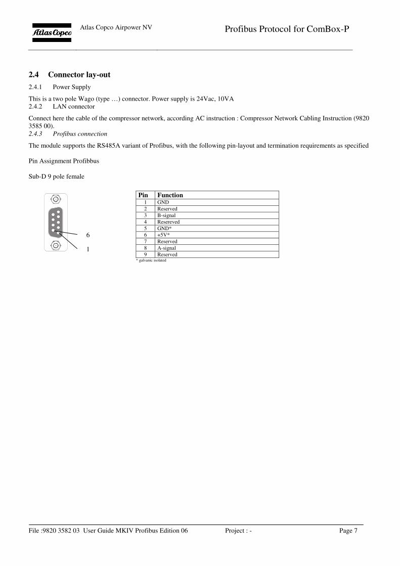
2.4.3 Profibus connection
The module supports the RS485A variant of Profibus, with the following pin-layout and termination requirements as specified
Pin Assignment Profibbus
Sub-D 9 pole female
Pin Function 1 GND
2 Reserved
3 B-signal
4 Resereved
5 GND*
6 +5V*
7 Reserved
8 A-signal
9 Reserved * galvanic isolated
1
6
Atlas Copco Airpower NV
Profibus Protocol for ComBox-P
File :9820 3582 03 User Guide MKIV Profibus Edition 06 Project : - Page 8
3 Basic Protocol
The profile is based on the standard Profibus-DP protocol, with following basic specifications:
• DP-Slave on Siemens SPC3 Asic
• RS485
• Baudrate: 9.600 Kbaud to 12.000 Mbaud
• Autobaud: supported
• Freeze Mode: Not supported
• Sync Mode: Not supported
• Slave Node Address Change: not supported
• Diagnostics : not supported
4 Profile definition
4.1 Master – Slave concept
The profile is based upon the master-slave principle. This means all communication is initiated by the master and a reply is
generated by the slave (ComBox-P).
All buffers should be full length consistent.
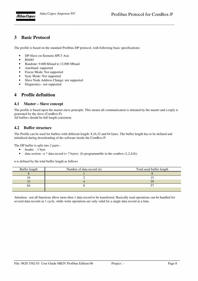
4.2 Buffer structure
The Profile can be used for buffers with different length: 8,16,32 and 64 bytes. The buffer length has to be defined and
initialised during downloading of the software inside the ComBox-P.
The DP buffer is split into 2 parts :
• header : 1 byte
• data section : n * data record (= 7 bytes) (Is programmeble in the combox (1,2,4,8))
n is defined by the total buffer length as follows
Buffer length Number of data record (n) Total used buffer length
8 1 8
16 2 15
32 4 29
64 8 57
Attention : not all functions allow more then 1 data record to be transferred. Basically read operations can be handled for
several data records in 1 cycle, while write operations are only valid for a single data record at a time.
Atlas Copco Airpower NV
Profibus Protocol for ComBox-P
File :9820 3582 03 User Guide MKIV Profibus Edition 06 Project : - Page 9
4.3 Header
The header is a 1 byte value that is bit encoded. The interpretation is different for Master->slave and Slave->Master
communication.
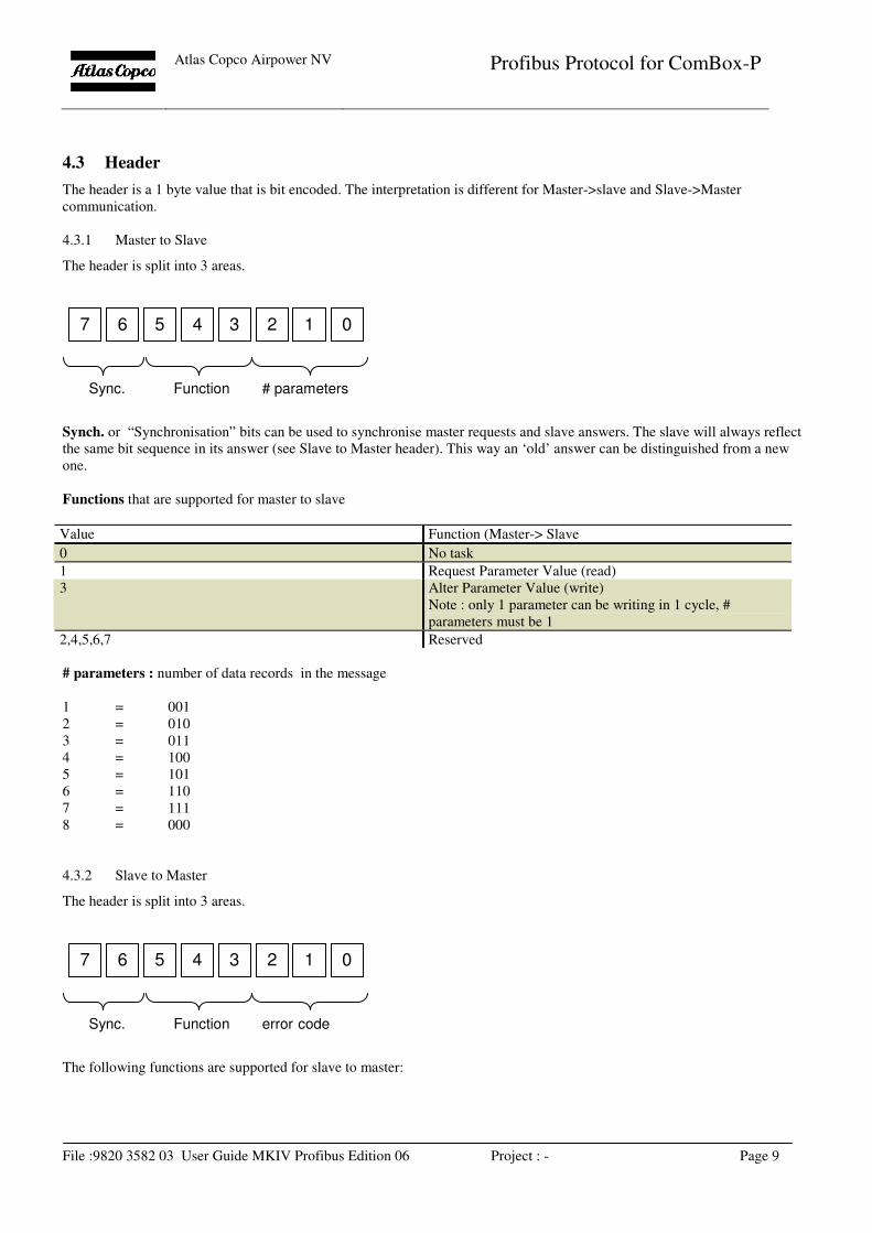
4.3.1 Master to Slave
The header is split into 3 areas.
Synch. or “Synchronisation” bits can be used to synchronise master requests and slave answers. The slave will always reflect
the same bit sequence in its answer (see Slave to Master header). This way an ‘old’ answer can be distinguished from a new
one.
Functions that are supported for master to slave
Value Function (Master-> Slave
0 No task
1 Request Parameter Value (read)
3 Alter Parameter Value (write)
Note : only 1 parameter can be writing in 1 cycle, #
parameters must be 1
2,4,5,6,7 Reserved
# parameters : number of data records in the message
1 = 001
2 = 010
3 = 011
4 = 100
5 = 101
6 = 110
7 = 111
8 = 000
4.3.2 Slave to Master
The header is split into 3 areas.
The following functions are supported for slave to master:
0 1 2 3 4 5 6 7
Function # parameters Sync.
0 1 2 3 4 5 6 7
Function error code Sync.
Atlas Copco Airpower NV
Profibus Protocol for ComBox-P
File :9820 3582 03 User Guide MKIV Profibus Edition 06 Project : - Page 10
Value Function (Master-> Slave
0 No task, or no data yet
2 Transmit Parameter Value (s)
7 Task not possible
1,3,4,5,6 Reserved
Synch. or “Synchronisation” bits will be set identical to the bits from the master-slave request.
Error Code :
Error Code Explanation
0 No Error
1 Nr of Data Records are not Correct
2 Function is not correct
3 Number of Data Records for reprogramming not correct
(Only one Data record).
Atlas Copco Airpower NV
Profibus Protocol for ComBox-P
File :9820 3582 03 User Guide MKIV Profibus Edition 06 Project : - Page 11
4.4 Data Record
Each data record is 7 bytes long and contains the following info:
• Node Address : 1 bytes, CAN address of slave to connect to
• Parameter ID : 2 bytes, ID of the parameter to read/write Data : 4 bytes, containing actual data
4.4.1 Node Address
This is the Elektronikon MkIV CAN address : 1 to 30 (31 only used for default factory setting, should not be used in network).
Additional error info : bit 7 (highest bit) will be set to 1 in a Slave to Master Data Record, if this data record contains an error.
Atlas Copco Airpower NV
Profibus Protocol for ComBox-P
File :9820 3582 03 User Guide MKIV Profibus Edition 06 Project : - Page 12
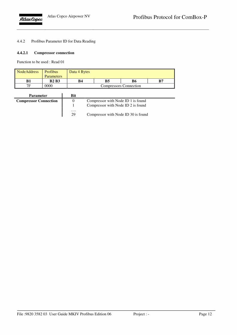
4.4.2 Profibus Parameter ID for Data Reading
4.4.2.1 Compressor connection
Function to be used : Read 01
NodeAddress Profibus
Parameters
Data 4 Bytes
B1 B2 B3 B4 B5 B6 B7
7F 0000 Compressors Connection
Parameter Bit
Compressor Connection 0 Compressor with Node ID 1 is found
1 Compressor with Node ID 2 is found
….
29 Compressor with Node ID 30 is found
Atlas Copco Airpower NV
Profibus Protocol for ComBox-P
File :9820 3582 03 User Guide MKIV Profibus Edition 06 Project : - Page 13
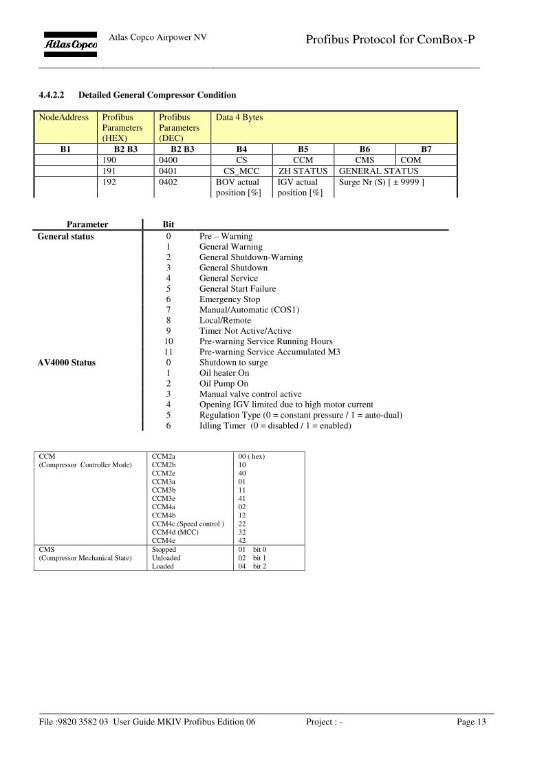
4.4.2.2 Detailed General Compressor Condition
NodeAddress Profibus
Parameters
(HEX)
Profibus
Parameters
(DEC)
Data 4 Bytes
B1 B2 B3 B2 B3 B4 B5 B6 B7
190 0400 CS CCM CMS COM
191 0401 CS_MCC ZH STATUS GENERAL STATUS
192 0402 BOV actual
position [%]
IGV actual
position [%]
Surge Nr (S) [ ± 9999 ]
Parameter Bit
General status 0 Pre – Warning
1 General Warning
2 General Shutdown-Warning
3 General Shutdown
4 General Service
5 General Start Failure
6 Emergency Stop
7 Manual/Automatic (COS1)
8 Local/Remote
9 Timer Not Active/Active
10 Pre-warning Service Running Hours
11 Pre-warning Service Accumulated M3
AV4000 Status 0 Shutdown to surge
1 Oil heater On
2 Oil Pump On
3 Manual valve control active
4 Opening IGV limited due to high motor current
5 Regulation Type (0 = constant pressure / 1 = auto-dual)
6 Idling Timer (0 = disabled / 1 = enabled)
CCM
(Compressor Controller Mode)
CCM2a
CCM2b
CCM2e
CCM3a
CCM3b
CCM3e
CCM4a
CCM4b
CCM4c (Speed control )
CCM4d (MCC)
CCM4e
00 ( hex)
10
40
01
11
41
02
12
22
32
42
CMS
(Compressor Mechanical State)
Stopped
Unloaded
Loaded
01 bit 0
02 bit 1
04 bit 2
Atlas Copco Airpower NV
Profibus Protocol for ComBox-P
File :9820 3582 03 User Guide MKIV Profibus Edition 06 Project : - Page 14
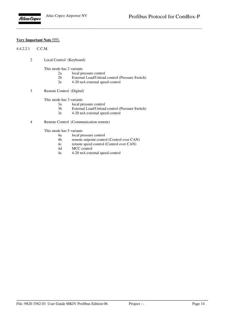
Very Important Note !!!!!.
4.4.2.2.1 C.C.M.
2 Local Control (Keyboard)
This mode has 2 variants
2a local pressure control
2b External Load/Unload control (Pressure Switch)
2e 4-20 mA external speed control
3 Remote Control (Digital)
This mode has 3 variants
3a local pressure control
3b External Load/Unload control (Pressure Switch)
3e 4-20 mA external speed control
4 Remote Control (Communication remote)
This mode has 5 variants
4a local pressure control
4b remote setpoint control (Control over CAN)
4c remote speed control (Control over CAN)
4d MCC control
4e 4-20 mA external speed control
Atlas Copco Airpower NV
Profibus Protocol for ComBox-P
File :9820 3582 03 User Guide MKIV Profibus Edition 06 Project : - Page 15
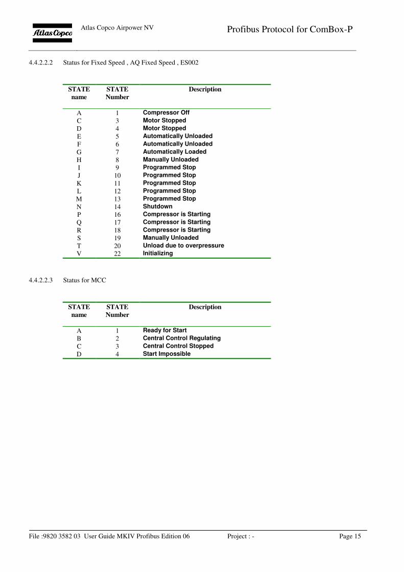
4.4.2.2.2 Status for Fixed Speed , AQ Fixed Speed , ES002
STATE
name
STATE
Number
Description
A 1 Compressor Off
C 3 Motor Stopped
D 4 Motor Stopped
E 5 Automatically Unloaded
F 6 Automatically Unloaded
G 7 Automatically Loaded
H 8 Manually Unloaded
I 9 Programmed Stop
J 10 Programmed Stop
K 11 Programmed Stop
L 12 Programmed Stop
M 13 Programmed Stop
N 14 Shutdown
P 16 Compressor is Starting
Q 17 Compressor is Starting
R 18 Compressor is Starting
S 19 Manually Unloaded
T 20 Unload due to overpressure
V 22 Initializing
4.4.2.2.3 Status for MCC
STATE
name
STATE
Number
Description
A 1 Ready for Start
B 2 Central Control Regulating
C 3 Central Control Stopped
D 4 Start Impossible
Atlas Copco Airpower NV
Profibus Protocol for ComBox-P
File :9820 3582 03 User Guide MKIV Profibus Edition 06 Project : - Page 16
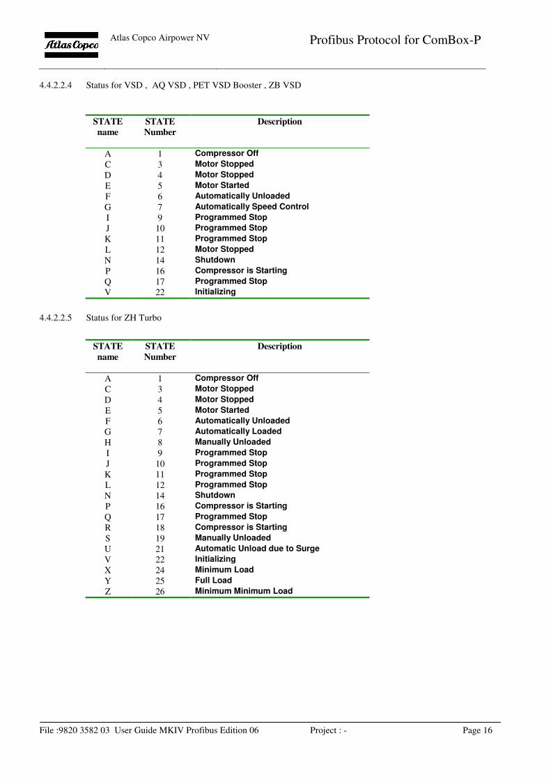
4.4.2.2.4 Status for VSD , AQ VSD , PET VSD Booster , ZB VSD
STATE
name
STATE
Number
Description
A 1 Compressor Off
C 3 Motor Stopped
D 4 Motor Stopped
E 5 Motor Started
F 6 Automatically Unloaded
G 7 Automatically Speed Control
I 9 Programmed Stop
J 10 Programmed Stop
K 11 Programmed Stop
L 12 Motor Stopped
N 14 Shutdown
P 16 Compressor is Starting
Q 17 Programmed Stop
V 22 Initializing
4.4.2.2.5 Status for ZH Turbo
STATE
name
STATE
Number
Description
A 1 Compressor Off
C 3 Motor Stopped
D 4 Motor Stopped
E 5 Motor Started
F 6 Automatically Unloaded
G 7 Automatically Loaded
H 8 Manually Unloaded
I 9 Programmed Stop
J 10 Programmed Stop
K 11 Programmed Stop
L 12 Programmed Stop
N 14 Shutdown
P 16 Compressor is Starting
Q 17 Programmed Stop
R 18 Compressor is Starting
S 19 Manually Unloaded
U 21 Automatic Unload due to Surge
V 22 Initializing
X 24 Minimum Load
Y 25 Full Load
Z 26 Minimum Minimum Load
Atlas Copco Airpower NV
Profibus Protocol for ComBox-P
File :9820 3582 03 User Guide MKIV Profibus Edition 06 Project : - Page 17
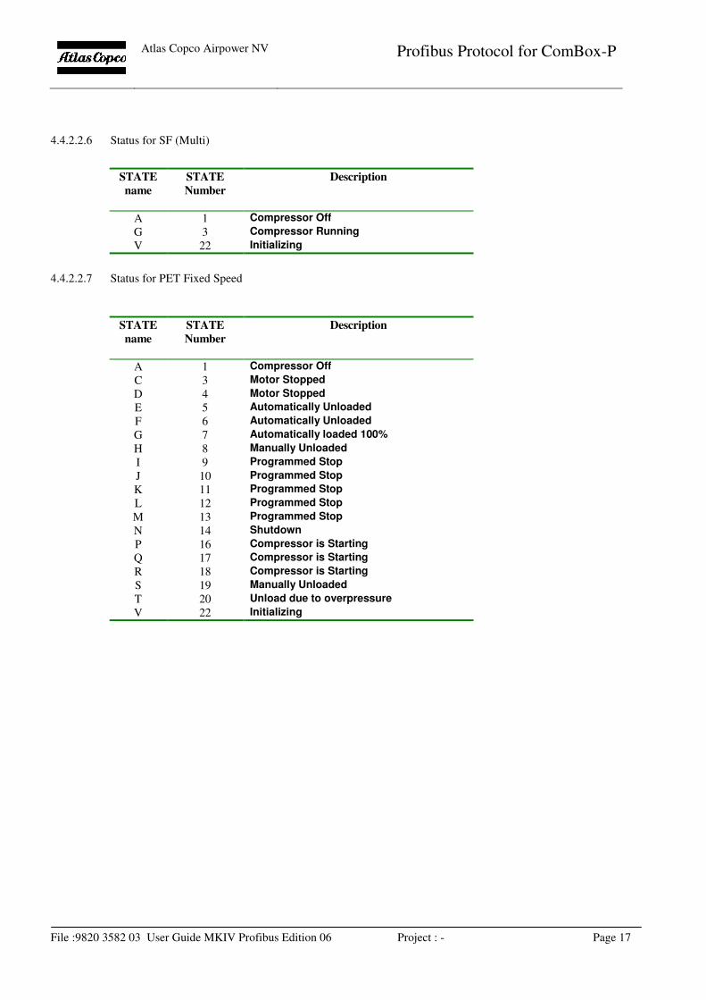
4.4.2.2.6 Status for SF (Multi)
STATE
name
STATE
Number
Description
A 1 Compressor Off
G 3 Compressor Running
V 22 Initializing
4.4.2.2.7 Status for PET Fixed Speed
STATE
name
STATE
Number
Description
A 1 Compressor Off
C 3 Motor Stopped
D 4 Motor Stopped
E 5 Automatically Unloaded
F 6 Automatically Unloaded
G 7 Automatically loaded 100%
H 8 Manually Unloaded
I 9 Programmed Stop
J 10 Programmed Stop
K 11 Programmed Stop
L 12 Programmed Stop
M 13 Programmed Stop
N 14 Shutdown
P 16 Compressor is Starting
Q 17 Compressor is Starting
R 18 Compressor is Starting
S 19 Manually Unloaded
T 20 Unload due to overpressure
V 22 Initializing
Atlas Copco Airpower NV
Profibus Protocol for ComBox-P
File :9820 3582 03 User Guide MKIV Profibus Edition 06 Project : - Page 18
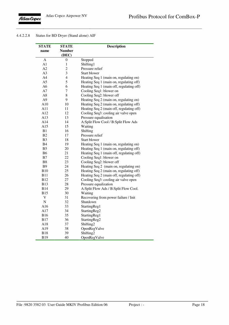
4.4.2.2.8 Status for BD Dryer (Stand alone) AIF
STATE
name
STATE
Number
(DEC)
Description
A 0 Stopped
A1 1 Shifting1
A2 2 Pressure relief
A3 3 Start blower
A4 4 Heating Seq 1 (main on, regulating on)
A5 5 Heating Seq 1 (main on, regulating off)
A6 6 Heating Seq 1 (main off, regulating off)
A7 7 Cooling Seq1: blower on
A8 8 Cooling Seq2: blower off
A9 9 Heating Seq 2 (main on, regulating on)
A10 10 Heating Seq 2 (main on, regulating off)
A11 11 Heating Seq 2 (main off, regulating off)
A12 12 Cooling Seq3: cooling air valve open
A13 13 Pressure equalisation
A14 14 A:Split Flow Cool / B:Split Flow Ads
A15 15 Waiting
B1 16 Shifting
B2 17 Pressure relief
B3 18 Start blower
B4 19 Heating Seq 1 (main on, regulating on)
B5 20 Heating Seq 1 (main on, regulating off)
B6 21 Heating Seq 1 (main off, regulating off)
B7 22 Cooling Seq1: blower on
B8 23 Cooling Seq2: blower off
B9 24 Heating Seq 2 (main on, regulating on)
B10 25 Heating Seq 2 (main on, regulating off)
B11 26 Heating Seq 2 (main off, regulating off)
B12 27 Cooling Seq3: cooling air valve open
B13 28 Pressure equalization
B14 29 A:Split Flow Ads / B:Split Flow Cool.
B15 30 Waiting
V 31 Recovering from power failure / Init
N 32 Shutdown
A16 33 StartingReg1
A17 34 StartingReg2
B16 35 StartingReg1
B17 36 StartingReg2
A18 37 Shifting2
A19 38 OpenRegValve
B18 39 Shifting2
B19 40 OpenRegValve
Atlas Copco Airpower NV
Profibus Protocol for ComBox-P
File :9820 3582 03 User Guide MKIV Profibus Edition 06 Project : - Page 19
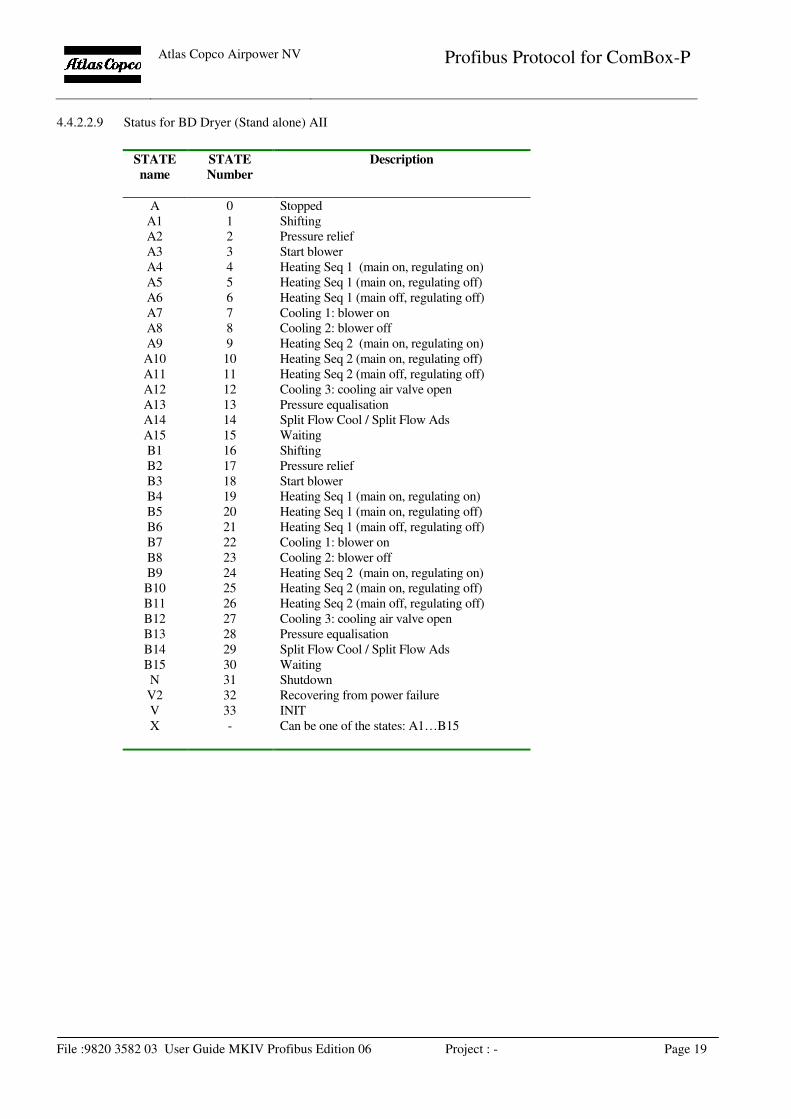
4.4.2.2.9 Status for BD Dryer (Stand alone) AII
STATE
name
STATE
Number
Description
A 0 Stopped
A1 1 Shifting
A2 2 Pressure relief
A3 3 Start blower
A4 4 Heating Seq 1 (main on, regulating on)
A5 5 Heating Seq 1 (main on, regulating off)
A6 6 Heating Seq 1 (main off, regulating off)
A7 7 Cooling 1: blower on
A8 8 Cooling 2: blower off
A9 9 Heating Seq 2 (main on, regulating on)
A10 10 Heating Seq 2 (main on, regulating off)
A11 11 Heating Seq 2 (main off, regulating off)
A12 12 Cooling 3: cooling air valve open
A13 13 Pressure equalisation
A14 14 Split Flow Cool / Split Flow Ads
A15 15 Waiting
B1 16 Shifting
B2 17 Pressure relief
B3 18 Start blower
B4 19 Heating Seq 1 (main on, regulating on)
B5 20 Heating Seq 1 (main on, regulating off)
B6 21 Heating Seq 1 (main off, regulating off)
B7 22 Cooling 1: blower on
B8 23 Cooling 2: blower off
B9 24 Heating Seq 2 (main on, regulating on)
B10 25 Heating Seq 2 (main on, regulating off)
B11 26 Heating Seq 2 (main off, regulating off)
B12 27 Cooling 3: cooling air valve open
B13 28 Pressure equalisation
B14 29 Split Flow Cool / Split Flow Ads
B15 30 Waiting
N 31 Shutdown
V2 32 Recovering from power failure
V 33 INIT
X - Can be one of the states: A1…B15
Atlas Copco Airpower NV
Profibus Protocol for ComBox-P
File :9820 3582 03 User Guide MKIV Profibus Edition 06 Project : - Page 20
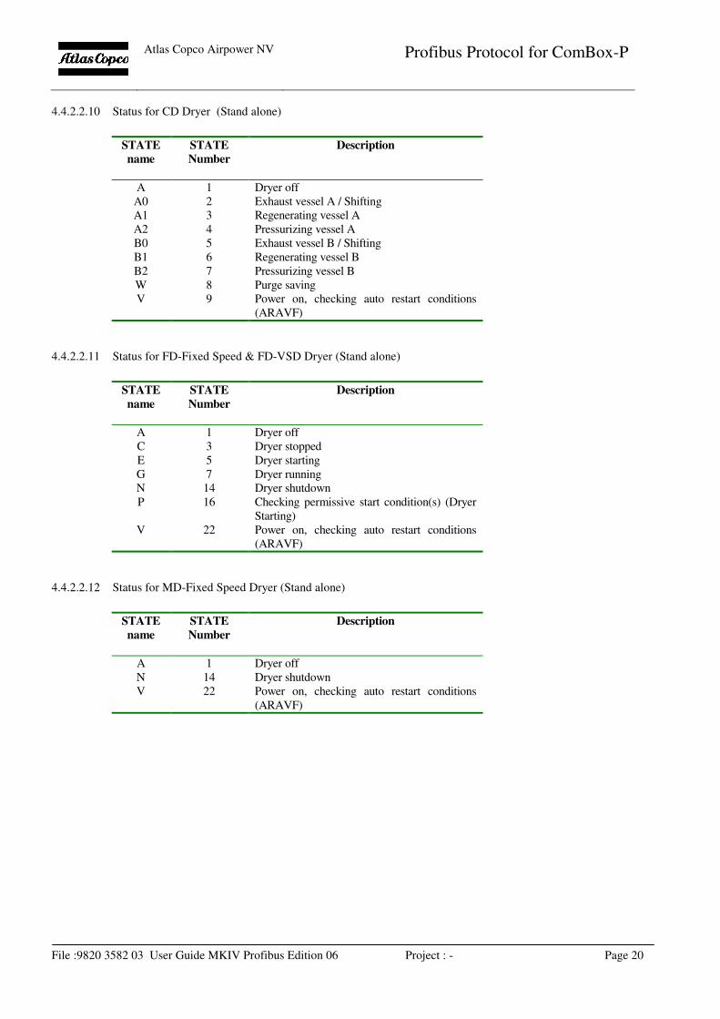
4.4.2.2.10 Status for CD Dryer (Stand alone)
STATE
name
STATE
Number
Description
A 1 Dryer off
A0 2 Exhaust vessel A / Shifting
A1 3 Regenerating vessel A
A2 4 Pressurizing vessel A
B0 5 Exhaust vessel B / Shifting
B1 6 Regenerating vessel B
B2 7 Pressurizing vessel B
W 8 Purge saving
V 9 Power on, checking auto restart conditions
(ARAVF)
4.4.2.2.11 Status for FD-Fixed Speed & FD-VSD Dryer (Stand alone)
STATE
name
STATE
Number
Description
A 1 Dryer off
C 3 Dryer stopped
E 5 Dryer starting
G 7 Dryer running
N 14 Dryer shutdown
P 16 Checking permissive start condition(s) (Dryer
Starting)
V 22 Power on, checking auto restart conditions
(ARAVF)
4.4.2.2.12 Status for MD-Fixed Speed Dryer (Stand alone)
STATE
name
STATE
Number
Description
A 1 Dryer off
N 14 Dryer shutdown
V 22 Power on, checking auto restart conditions
(ARAVF)
Atlas Copco Airpower NV
Profibus Protocol for ComBox-P
File :9820 3582 03 User Guide MKIV Profibus Edition 06 Project : - Page 21
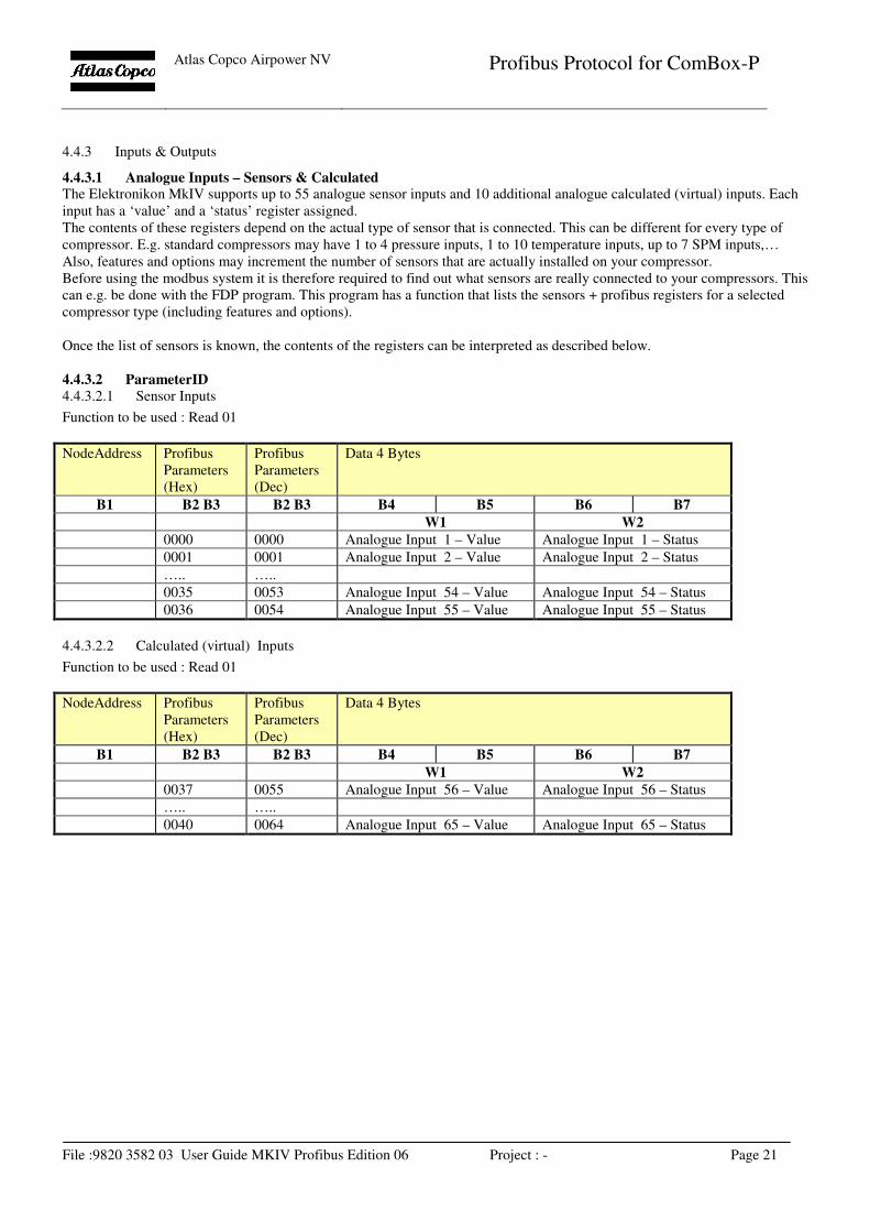
4.4.3 Inputs & Outputs
4.4.3.1 Analogue Inputs – Sensors & Calculated The Elektronikon MkIV supports up to 55 analogue sensor inputs and 10 additional analogue calculated (virtual) inputs. Each
input has a ‘value’ and a ‘status’ register assigned.
The contents of these registers depend on the actual type of sensor that is connected. This can be different for every type of
compressor. E.g. standard compressors may have 1 to 4 pressure inputs, 1 to 10 temperature inputs, up to 7 SPM inputs,…
Also, features and options may increment the number of sensors that are actually installed on your compressor.
Before using the modbus system it is therefore required to find out what sensors are really connected to your compressors. This
can e.g. be done with the FDP program. This program has a function that lists the sensors + profibus registers for a selected
compressor type (including features and options).
Once the list of sensors is known, the contents of the registers can be interpreted as described below.
4.4.3.2 ParameterID
4.4.3.2.1 Sensor Inputs
Function to be used : Read 01
NodeAddress Profibus
Parameters
(Hex)
Profibus
Parameters
(Dec)
Data 4 Bytes
B1 B2 B3 B2 B3 B4 B5 B6 B7
W1 W2
0000 0000 Analogue Input 1 – Value Analogue Input 1 – Status
0001 0001 Analogue Input 2 – Value Analogue Input 2 – Status
….. …..
0035 0053 Analogue Input 54 – Value Analogue Input 54 – Status
0036 0054 Analogue Input 55 – Value Analogue Input 55 – Status
4.4.3.2.2 Calculated (virtual) Inputs
Function to be used : Read 01
NodeAddress Profibus
Parameters
(Hex)
Profibus
Parameters
(Dec)
Data 4 Bytes
B1 B2 B3 B2 B3 B4 B5 B6 B7
W1 W2
0037 0055 Analogue Input 56 – Value Analogue Input 56 – Status
….. …..
0040 0064 Analogue Input 65 – Value Analogue Input 65 – Status
Atlas Copco Airpower NV
Profibus Protocol for ComBox-P
File :9820 3582 03 User Guide MKIV Profibus Edition 06 Project : - Page 22
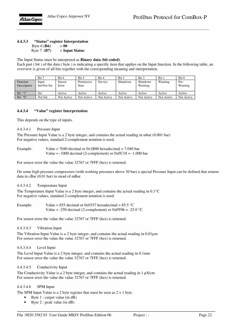
4.4.3.3 “Status” register Interpretation
Byte 6 (B6) = 00
Byte 7 (B7) = Input Status
The Input Status must be interpreted as Binary data (bit coded).
Each part ( bit ) of the data ( byte ) is indicating a specific item that applies on the Input function. In the following table, an
overview is given of all bits together with the corresponding meaning and interpretation.
Bit 7 Bit 6 Bit 5 Bit 4 Bit 3 Bit 2 Bit 1 Bit 0
Function
Description
Input
Set/Not Set
Sensor
Error
Permissive
Start
Service
Shutdown Shutdown
Warning
Warning Pre-
Warning
Bit “1” Set Active Active Active Active Active Active Active
Bit “0” Not Set Not Active Not Active Not Active Not Active Not Active Not Active Not Active
4.4.3.4 “Value” register Interpretation
This depends on the type of inputs.
4.4.3.4.1 Pressure Input
The Pressure Input Value is a 2 byte integer, and contains the actual reading in mbar (0.001 bar)
For negative values, standard 2-complement notation is used.
Example: Value = 7040 decimal or 0x1B80 hexadecimal = 7.040 bar.
Value = -1000 decimal (2-complement) or 0xFC18 = -1.000 bar
For sensor error the value the value 32767 or 7FFF (hex) is returned.
On some high pressure compressors (with working pressures above 30 bar) a special Pressure Input can be defined that returns
data in cBar (0.01 bar) in stead of mBar.
4.4.3.4.2 Temperature Input
The Temperature Input Value is a 2 byte integer, and contains the actual reading in 0.1°C
For negative values, standard 2-complement notation is used.
Example: Value = 855 decimal or 0x0357 hexadecimal = 85.5 °C
Value = -250 decimal (2-complement) or 0xFF06 = -25.0 °C
For sensor error the value the value 32767 or 7FFF (hex) is returned.
4.4.3.4.3 Vibration Input
The Vibration Input Value is a 2 byte integer, and contains the actual reading in 0.01µm
For sensor error the value the value 32767 or 7FFF (hex) is returned.
4.4.3.4.4 Level Input
The Level Input Value is a 2 byte integer, and contains the actual reading in 0.1mm
For sensor error the value the value 32767 or 7FFF (hex) is returned.
4.4.3.4.5 Conductivity Input
The Conductivity Value is a 2 byte integer, and contains the actual reading in 1 µS/cm
For sensor error the value the value 32767 or 7FFF (hex) is returned.
4.4.3.4.6 SPM Input
The SPM Input Value is a 2 byte register that must be seen as 2 x 1 byte.
• Byte 1 : carpet value (in dB)
• Byte 2 : peak value (in dB)
Atlas Copco Airpower NV
Profibus Protocol for ComBox-P
File :9820 3582 03 User Guide MKIV Profibus Edition 06 Project : - Page 23
Example: Value = 0x1120 = > carpet value = 0x11, peak value = 0x20
For sensor error the value the value 0X7FFF (hex) is returned.
SPM values cannot be negative
4.4.3.4.7 Current Input
The Current Input Value is a 2 byte integer, and contains the actual reading in 0.1 A
For sensor error the value the value 32767 or 7FFF (hex) is returned.
4.4.3.4.8 Speed Input
The Speed Input Value is a 2 byte integer, and contains the actual reading in 1 rpm
For sensor error the value the value 32767 or 7FFF (hex) is returned.
Atlas Copco Airpower NV
Profibus Protocol for ComBox-P
File :9820 3582 03 User Guide MKIV Profibus Edition 06 Project : - Page 24
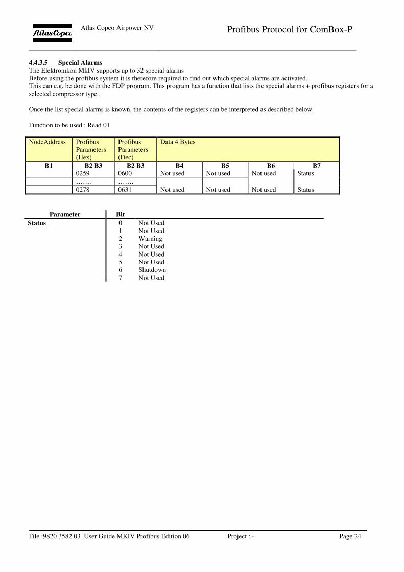
4.4.3.5 Special Alarms
The Elektronikon MkIV supports up to 32 special alarms
Before using the profibus system it is therefore required to find out which special alarms are activated.
This can e.g. be done with the FDP program. This program has a function that lists the special alarms + profibus registers for a
selected compressor type .
Once the list special alarms is known, the contents of the registers can be interpreted as described below.
Function to be used : Read 01
NodeAddress Profibus
Parameters
(Hex)
Profibus
Parameters
(Dec)
Data 4 Bytes
B1 B2 B3 B2 B3 B4 B5 B6 B7 0259 0600 Not used Not used Not used Status
……. …….
0278 0631 Not used Not used Not used Status
Parameter Bit
Status 0 Not Used
1 Not Used
2 Warning
3 Not Used
4 Not Used
5 Not Used
6 Shutdown
7 Not Used
Atlas Copco Airpower NV
Profibus Protocol for ComBox-P
File :9820 3582 03 User Guide MKIV Profibus Edition 06 Project : - Page 25
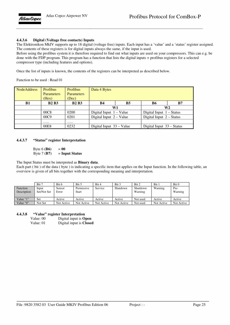
4.4.3.6 Digital (Voltage free contacts) Inputs
The Elektronikon MkIV supports up to 18 digital (voltage free) inputs. Each input has a ‘value’ and a ‘status’ register assigned.
The contents of these registers is for digital inputs always the same, if the input is used.
Before using the profibus system it is therefore required to find out what inputs are used on your compressors. This can e.g. be
done with the FDP program. This program has a function that lists the digital inputs + profibus registers for a selected
compressor type (including features and options).
Once the list of inputs is known, the contents of the registers can be interpreted as described below.
Function to be used : Read 01
NodeAddress Profibus
Parameters
(Hex)
Profibus
Parameters
(Dec)
Data 4 Bytes
B1 B2 B3 B2 B3 B4 B5 B6 B7
W1 W2
00C8 0200 Digital Input 1 – Value Digital Input 1 – Status
00C9 0201 Digital Input 2 – Value Digital Input 2 – Status
….. …..
00E8 0232 Digital Input 33 – Value Digital Input 33 – Status
4.4.3.7 “Status” register Interpretation
Byte 6 (B6) = 00
Byte 7 (B7) = Input Status
The Input Status must be interpreted as Binary data.
Each part ( bit ) of the data ( byte ) is indicating a specific item that applies on the Input function. In the following table, an
overview is given of all bits together with the corresponding meaning and interpretation.
Bit 7 Bit 6 Bit 5 Bit 4 Bit 3 Bit 2 Bit 1 Bit 0
Function
Description
Input
Set/Not Set
Sensor
Error
Permissive
Start
Service
Shutdown Shutdown
Warning
Warning Pre-
Warning
Value “1” Set Active Active Active Active Not used Active Active
Value “0” Not Set Not Active Not Active Not Active Not Active Not used Not Active Not Active
4.4.3.8 “Value” register Interpretation
Value: 00 Digital input is Open
Value: 01 Digital input is Closed
Atlas Copco Airpower NV
Profibus Protocol for ComBox-P
File :9820 3582 03 User Guide MKIV Profibus Edition 06 Project : - Page 26
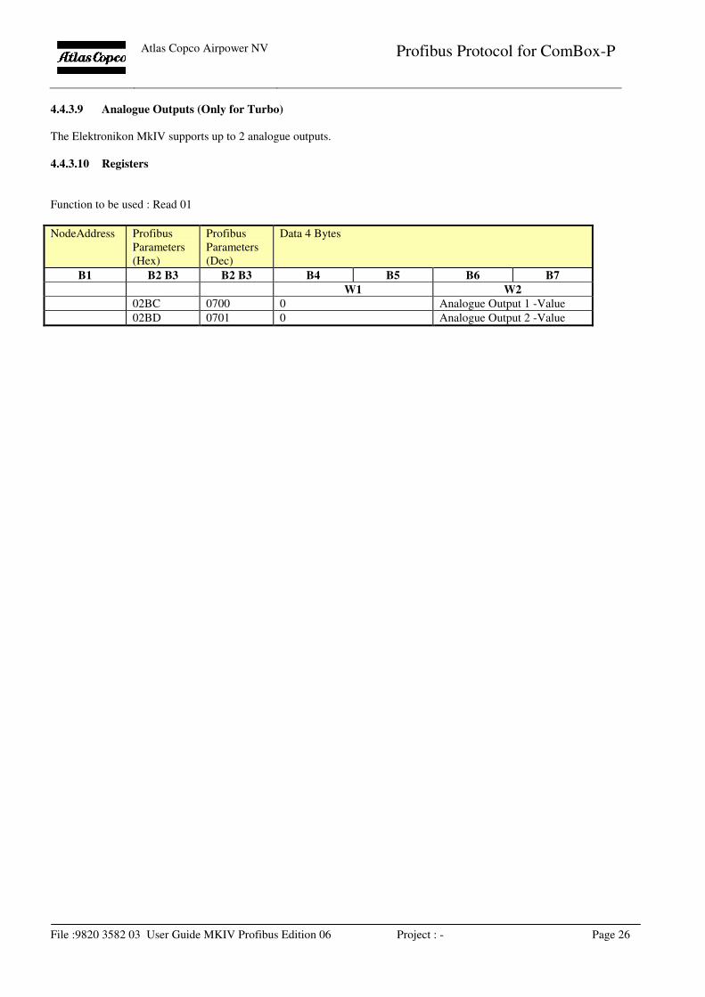
4.4.3.9 Analogue Outputs (Only for Turbo)
The Elektronikon MkIV supports up to 2 analogue outputs.
4.4.3.10 Registers
Function to be used : Read 01
NodeAddress Profibus
Parameters
(Hex)
Profibus
Parameters
(Dec)
Data 4 Bytes
B1 B2 B3 B2 B3 B4 B5 B6 B7
W1 W2
02BC 0700 0 Analogue Output 1 -Value
02BD 0701 0 Analogue Output 2 -Value
Atlas Copco Airpower NV
Profibus Protocol for ComBox-P
File :9820 3582 03 User Guide MKIV Profibus Edition 06 Project : - Page 27
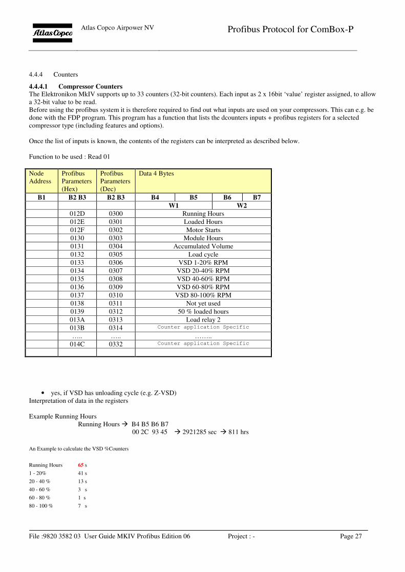
4.4.4 Counters
4.4.4.1 Compressor Counters The Elektronikon MkIV supports up to 33 counters (32-bit counters). Each input as 2 x 16bit ‘value’ register assigned, to allow
a 32-bit value to be read.
Before using the profibus system it is therefore required to find out what inputs are used on your compressors. This can e.g. be
done with the FDP program. This program has a function that lists the dcounters inputs + profibus registers for a selected
compressor type (including features and options).
Once the list of inputs is known, the contents of the registers can be interpreted as described below.
Function to be used : Read 01
Node
Address
Profibus
Parameters
(Hex)
Profibus
Parameters
(Dec)
Data 4 Bytes
B1 B2 B3 B2 B3 B4 B5 B6 B7
W1 W2
012D 0300 Running Hours
012E 0301 Loaded Hours
012F 0302 Motor Starts
0130 0303 Module Hours
0131 0304 Accumulated Volume
0132 0305 Load cycle
0133 0306 VSD 1-20% RPM
0134 0307 VSD 20-40% RPM
0135 0308 VSD 40-60% RPM
0136 0309 VSD 60-80% RPM
0137 0310 VSD 80-100% RPM
0138 0311 Not yet used
0139 0312 50 % loaded hours
013A 0313 Load relay 2
013B 0314 Counter application Specific
….. ….. ……..
014C 0332 Counter application Specific
• yes, if VSD has unloading cycle (e.g. Z-VSD)
Interpretation of data in the registers
Example Running Hours
Running Hours � B4 B5 B6 B7
00 2C 93 45 � 2921285 sec � 811 hrs
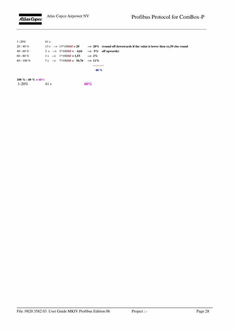
An Example to calculate the VSD %Counters
Running Hours 65 s
1 - 20% 41 s
20 - 40 % 13 s
40 - 60 % 3 s
60 - 80 % 1 s
80 - 100 % 7 s
Atlas Copco Airpower NV
Profibus Protocol for ComBox-P
File :9820 3582 03 User Guide MKIV Profibus Edition 06 Project : - Page 28
1 -20% 41 s
20 - 40 % 13 s --> 13*100/65 = 20 --> 20% (round off downwards if the value is lower then xx,50 else round
40 - 60 % 3 s --> 3*100/65 = 4,61 --> 5% off upwards)
60 - 80 % 1 s --> 1*100/65 = 1,53 --> 2%
80 - 100 % 7 s --> 7*100/65 = 10,76 --> 11%
----------
40 %
100 % - 40 % = 60%
1-20% 41 s 60%
Atlas Copco Airpower NV
Profibus Protocol for ComBox-P
File :9820 3582 03 User Guide MKIV Profibus Edition 06 Project : - Page 29
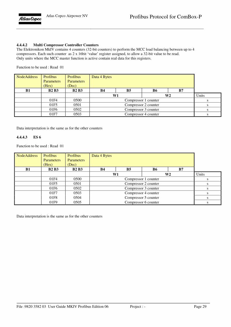
4.4.4.2 Multi Compressor Controller Counters
The Elektronikon MkIV contains 4 counters (32-bit counters) to perform the MCC load balancing between up to 4
compressors. Each such counter as 2 x 16bit ‘value’ register assigned, to allow a 32-bit value to be read.
Only units where the MCC master function is active contain real data for this registers.
Function to be used : Read 01
NodeAddress Profibus
Parameters
(Hex)
Profibus
Parameters
(Dec)
Data 4 Bytes
B1 B2 B3 B2 B3 B4 B5 B6 B7
W1 W2 Units
01F4 0500 Compressor 1 counter s
01F5 0501 Compressor 2 counter s
01F6 0502 Compressor 3 counter s
01F7 0503 Compressor 4 counter s
Data interpretation is the same as for the other counters
4.4.4.3 ES 6
Function to be used : Read 01
NodeAddress Profibus
Parameters
(Hex)
Profibus
Parameters
(Dec)
Data 4 Bytes
B1 B2 B3 B2 B3 B4 B5 B6 B7
W1 W2 Units
01F4 0500 Compressor 1 counter s
01F5 0501 Compressor 2 counter s
01F6 0502 Compressor 3 counter s
01F7 0503 Compressor 4 counter s
01F8 0504 Compressor 5 counter s
01F9 0505 Compressor 6 counter s
Data interpretation is the same as for the other counters
Atlas Copco Airpower NV
Profibus Protocol for ComBox-P
File :9820 3582 03 User Guide MKIV Profibus Edition 06 Project : - Page 30
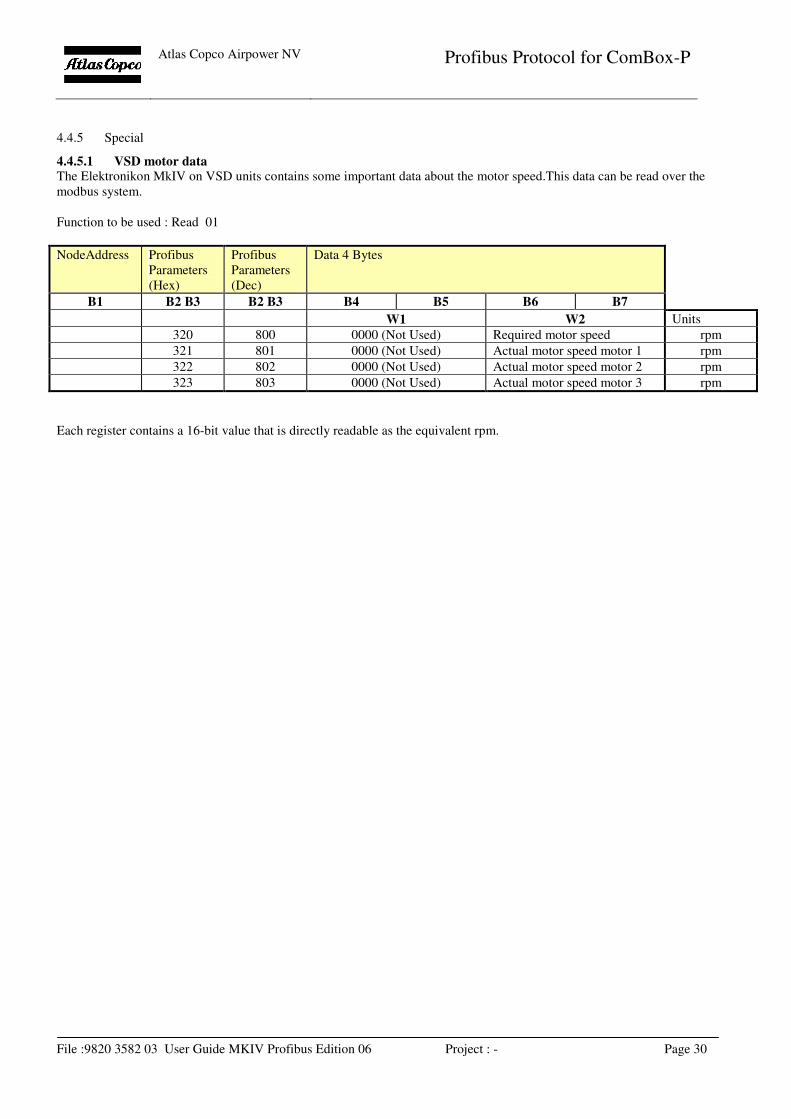
4.4.5 Special
4.4.5.1 VSD motor data The Elektronikon MkIV on VSD units contains some important data about the motor speed.This data can be read over the
modbus system.
Function to be used : Read 01
NodeAddress Profibus
Parameters
(Hex)
Profibus
Parameters
(Dec)
Data 4 Bytes
B1 B2 B3 B2 B3 B4 B5 B6 B7
W1 W2 Units
320 800 0000 (Not Used) Required motor speed rpm
321 801 0000 (Not Used) Actual motor speed motor 1 rpm
322 802 0000 (Not Used) Actual motor speed motor 2 rpm
323 803 0000 (Not Used) Actual motor speed motor 3 rpm
Each register contains a 16-bit value that is directly readable as the equivalent rpm.
Atlas Copco Airpower NV
Profibus Protocol for ComBox-P
File :9820 3582 03 User Guide MKIV Profibus Edition 06 Project : - Page 31
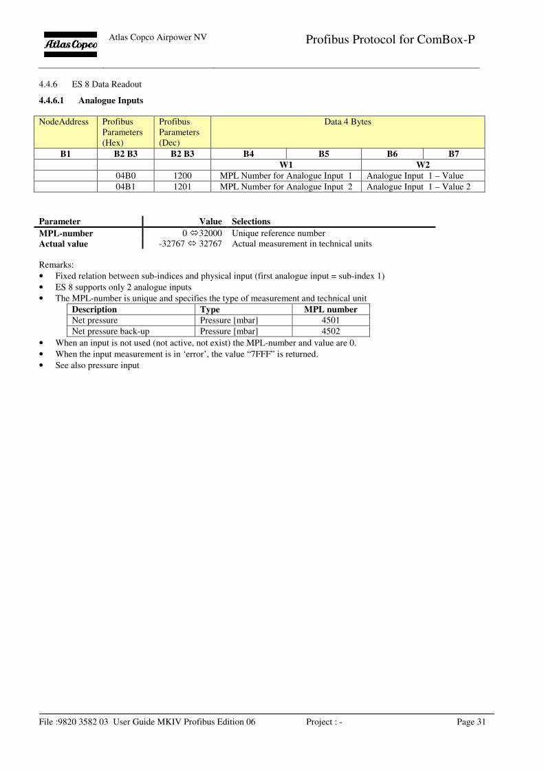
4.4.6 ES 8 Data Readout
4.4.6.1 Analogue Inputs
NodeAddress Profibus
Parameters
(Hex)
Profibus
Parameters
(Dec)
Data 4 Bytes
B1 B2 B3 B2 B3 B4 B5 B6 B7
W1 W2
04B0 1200 MPL Number for Analogue Input 1 Analogue Input 1 – Value
04B1 1201 MPL Number for Analogue Input 2 Analogue Input 1 – Value 2
Parameter Value Selections
MPL-number 0 �32000 Unique reference number
Actual value -32767 � 32767 Actual measurement in technical units
Remarks:
• Fixed relation between sub-indices and physical input (first analogue input = sub-index 1)
• ES 8 supports only 2 analogue inputs
• The MPL-number is unique and specifies the type of measurement and technical unit
Description Type MPL number
Net pressure Pressure [mbar] 4501
Net pressure back-up Pressure [mbar] 4502
• When an input is not used (not active, not exist) the MPL-number and value are 0.
• When the input measurement is in ‘error’, the value “7FFF” is returned.
• See also pressure input
Atlas Copco Airpower NV
Profibus Protocol for ComBox-P
File :9820 3582 03 User Guide MKIV Profibus Edition 06 Project : - Page 32
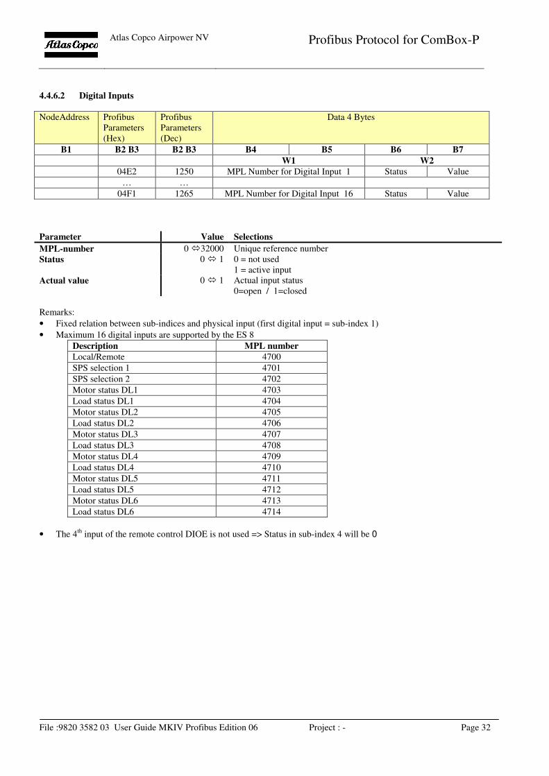
4.4.6.2 Digital Inputs
NodeAddress Profibus
Parameters
(Hex)
Profibus
Parameters
(Dec)
Data 4 Bytes
B1 B2 B3 B2 B3 B4 B5 B6 B7
W1 W2
04E2 1250 MPL Number for Digital Input 1 Status Value
… …
04F1 1265 MPL Number for Digital Input 16 Status Value
Parameter Value Selections
MPL-number 0 �32000 Unique reference number
Status 0 � 1 0 = not used
1 = active input
Actual value 0 � 1 Actual input status
0=open / 1=closed
Remarks:
• Fixed relation between sub-indices and physical input (first digital input = sub-index 1)
• Maximum 16 digital inputs are supported by the ES 8
Description MPL number
Local/Remote 4700
SPS selection 1 4701
SPS selection 2 4702
Motor status DL1 4703
Load status DL1 4704
Motor status DL2 4705
Load status DL2 4706
Motor status DL3 4707
Load status DL3 4708
Motor status DL4 4709
Load status DL4 4710
Motor status DL5 4711
Load status DL5 4712
Motor status DL6 4713
Load status DL6 4714
• The 4th
input of the remote control DIOE is not used => Status in sub-index 4 will be 0
Atlas Copco Airpower NV
Profibus Protocol for ComBox-P
File :9820 3582 03 User Guide MKIV Profibus Edition 06 Project : - Page 33
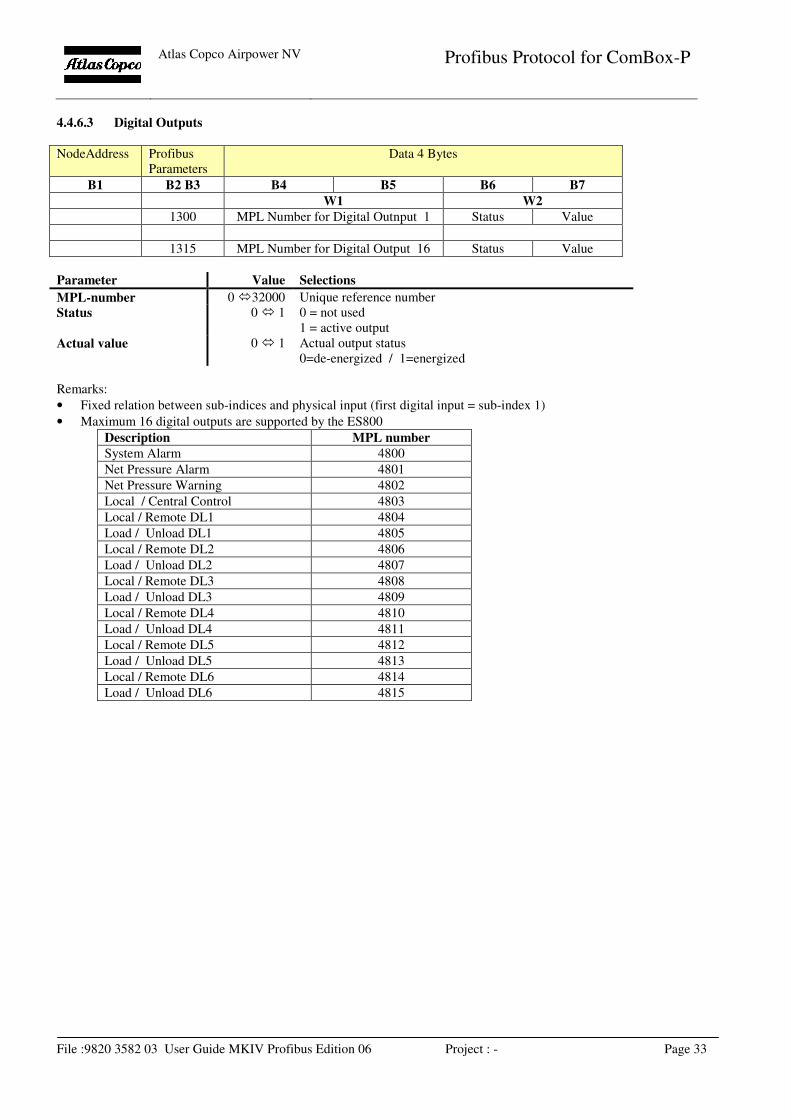
4.4.6.3 Digital Outputs
NodeAddress Profibus
Parameters
Data 4 Bytes
B1 B2 B3 B4 B5 B6 B7
W1 W2
1300 MPL Number for Digital Outnput 1 Status Value
1315 MPL Number for Digital Output 16 Status Value
Parameter Value Selections
MPL-number 0 �32000 Unique reference number
Status 0 � 1 0 = not used
1 = active output
Actual value 0 � 1 Actual output status
0=de-energized / 1=energized
Remarks:
• Fixed relation between sub-indices and physical input (first digital input = sub-index 1)
• Maximum 16 digital outputs are supported by the ES800
Description MPL number
System Alarm 4800
Net Pressure Alarm 4801
Net Pressure Warning 4802
Local / Central Control 4803
Local / Remote DL1 4804
Load / Unload DL1 4805
Local / Remote DL2 4806
Load / Unload DL2 4807
Local / Remote DL3 4808
Load / Unload DL3 4809
Local / Remote DL4 4810
Load / Unload DL4 4811
Local / Remote DL5 4812
Load / Unload DL5 4813
Local / Remote DL6 4814
Load / Unload DL6 4815
Atlas Copco Airpower NV
Profibus Protocol for ComBox-P
File :9820 3582 03 User Guide MKIV Profibus Edition 06 Project : - Page 34
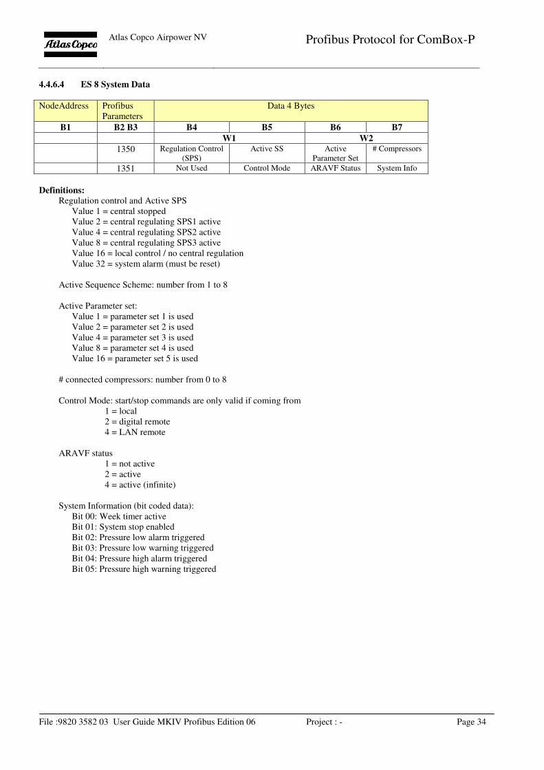
4.4.6.4 ES 8 System Data
NodeAddress Profibus
Parameters
Data 4 Bytes
B1 B2 B3 B4 B5 B6 B7
W1 W2
1350 Regulation Control
(SPS)
Active SS Active
Parameter Set
# Compressors
1351 Not Used Control Mode ARAVF Status System Info
Definitions:
Regulation control and Active SPS
Value 1 = central stopped
Value 2 = central regulating SPS1 active
Value 4 = central regulating SPS2 active
Value 8 = central regulating SPS3 active
Value 16 = local control / no central regulation
Value 32 = system alarm (must be reset)
Active Sequence Scheme: number from 1 to 8
Active Parameter set:
Value 1 = parameter set 1 is used
Value 2 = parameter set 2 is used
Value 4 = parameter set 3 is used
Value 8 = parameter set 4 is used
Value 16 = parameter set 5 is used
# connected compressors: number from 0 to 8
Control Mode: start/stop commands are only valid if coming from
1 = local
2 = digital remote
4 = LAN remote
ARAVF status
1 = not active
2 = active
4 = active (infinite)
System Information (bit coded data):
Bit 00: Week timer active
Bit 01: System stop enabled
Bit 02: Pressure low alarm triggered
Bit 03: Pressure low warning triggered
Bit 04: Pressure high alarm triggered
Bit 05: Pressure high warning triggered
Atlas Copco Airpower NV
Profibus Protocol for ComBox-P
File :9820 3582 03 User Guide MKIV Profibus Edition 06 Project : - Page 35
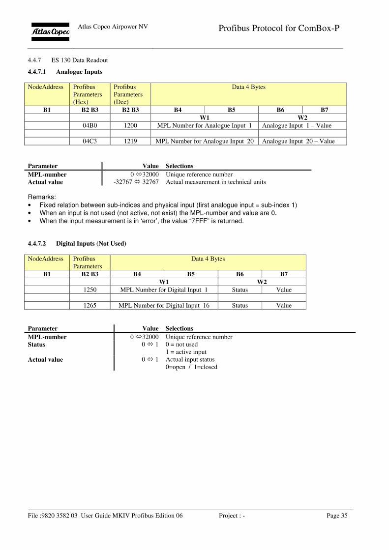
4.4.7 ES 130 Data Readout
4.4.7.1 Analogue Inputs
NodeAddress Profibus
Parameters
(Hex)
Profibus
Parameters
(Dec)
Data 4 Bytes
B1 B2 B3 B2 B3 B4 B5 B6 B7
W1 W2
04B0 1200 MPL Number for Analogue Input 1 Analogue Input 1 – Value
04C3 1219 MPL Number for Analogue Input 20 Analogue Input 20 – Value
Parameter Value Selections
MPL-number 0 �32000 Unique reference number
Actual value -32767 � 32767 Actual measurement in technical units
Remarks:
• Fixed relation between sub-indices and physical input (first analogue input = sub-index 1)
• When an input is not used (not active, not exist) the MPL-number and value are 0.
• When the input measurement is in ‘error’, the value “7FFF” is returned.
4.4.7.2 Digital Inputs (Not Used)
NodeAddress Profibus
Parameters
Data 4 Bytes
B1 B2 B3 B4 B5 B6 B7
W1 W2
1250 MPL Number for Digital Input 1 Status Value
1265 MPL Number for Digital Input 16 Status Value
Parameter Value Selections
MPL-number 0 �32000 Unique reference number
Status 0 � 1 0 = not used
1 = active input
Actual value 0 � 1 Actual input status
0=open / 1=closed
Atlas Copco Airpower NV
Profibus Protocol for ComBox-P
File :9820 3582 03 User Guide MKIV Profibus Edition 06 Project : - Page 36
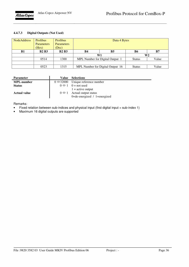
4.4.7.3 Digital Outputs (Not Used)
NodeAddress Profibus
Parameters
(Hex)
Profibus
Parameters
(Dec)
Data 4 Bytes
B1 B2 B3 B2 B3 B4 B5 B6 B7
W1 W2
0514 1300 MPL Number for Digital Output 1 Status Value
0523 1315 MPL Number for Digital Output 16 Status Value
Parameter Value Selections
MPL-number 0 �32000 Unique reference number
Status 0 � 1 0 = not used
1 = active output
Actual value 0 � 1 Actual output status
0=de-energized / 1=energized
Remarks:
• Fixed relation between sub-indices and physical input (first digital input = sub-index 1)
• Maximum 16 digital outputs are supported
Atlas Copco Airpower NV
Profibus Protocol for ComBox-P
File :9820 3582 03 User Guide MKIV Profibus Edition 06 Project : - Page 37
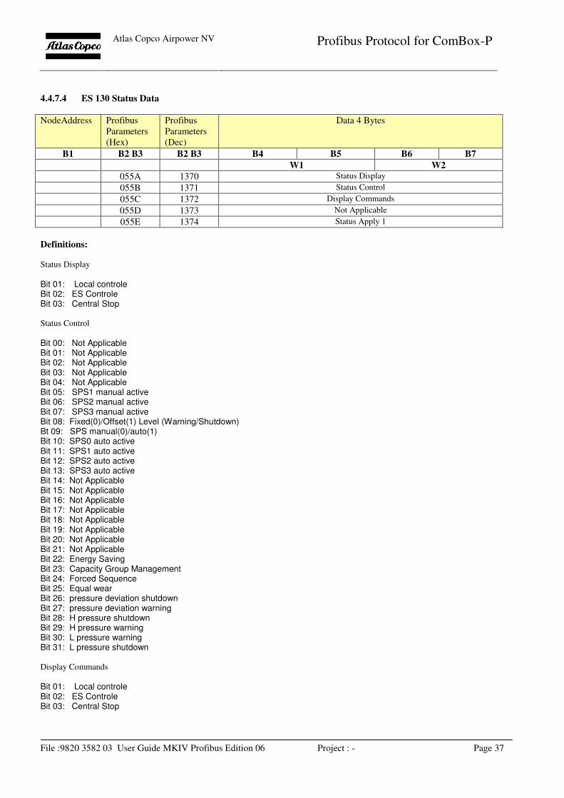
4.4.7.4 ES 130 Status Data
NodeAddress Profibus
Parameters
(Hex)
Profibus
Parameters
(Dec)
Data 4 Bytes
B1 B2 B3 B2 B3 B4 B5 B6 B7
W1 W2
055A 1370 Status Display
055B 1371 Status Control
055C 1372 Display Commands
055D 1373 Not Applicable
055E 1374 Status Apply 1
Definitions:
Status Display
Bit 01: Local controle Bit 02: ES Controle Bit 03: Central Stop
Status Control Bit 00: Not Applicable Bit 01: Not Applicable Bit 02: Not Applicable Bit 03: Not Applicable Bit 04: Not Applicable Bit 05: SPS1 manual active Bit 06: SPS2 manual active Bit 07: SPS3 manual active Bit 08: Fixed(0)/Offset(1) Level (Warning/Shutdown) Bt 09: SPS manual(0)/auto(1) Bit 10: SPS0 auto active Bit 11: SPS1 auto active Bit 12: SPS2 auto active Bit 13: SPS3 auto active Bit 14: Not Applicable Bit 15: Not Applicable Bit 16: Not Applicable Bit 17: Not Applicable Bit 18: Not Applicable Bit 19: Not Applicable Bit 20: Not Applicable Bit 21: Not Applicable Bit 22: Energy Saving Bit 23: Capacity Group Management Bit 24: Forced Sequence Bit 25: Equal wear Bit 26: pressure deviation shutdown Bit 27: pressure deviation warning Bit 28: H pressure shutdown Bit 29: H pressure warning Bit 30: L pressure warning Bit 31: L pressure shutdown Display Commands Bit 01: Local controle Bit 02: ES Controle Bit 03: Central Stop
Atlas Copco Airpower NV
Profibus Protocol for ComBox-P
File :9820 3582 03 User Guide MKIV Profibus Edition 06 Project : - Page 38
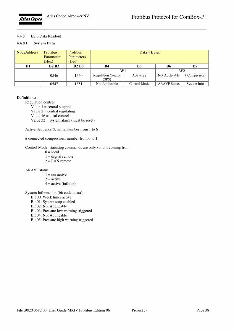
4.4.8 ES 6 Data Readout
4.4.8.1 System Data
NodeAddress Profibus
Parameters
(Hex)
Profibus
Parameters
(Dec)
Data 4 Bytes
B1 B2 B3 B2 B3 B4 B5 B6 B7
W1 W2
0546 1350 Regulation Control
(SPS)
Active SS Not Applicable # Compressors
0547 1351 Not Applicable Control Mode ARAVF Status System Info
Definitions:
Regulation control
Value 1 = central stopped
Value 2 = central regulating
Value 16 = local control
Value 32 = system alarm (must be reset)
Active Sequence Scheme: number from 1 to 6
# connected compressors: number from 0 to 1
Control Mode: start/stop commands are only valid if coming from
0 = local
1 = digital remote
2 = LAN remote
ARAVF status
1 = not active
2 = active
4 = active (infinite)
System Information (bit coded data):
Bit 00: Week timer active
Bit 01: System stop enabled
Bit 02: Not Applicable
Bit 03: Pressure low warning triggered
Bit 04: Not Applicable
Bit 05: Pressure high warning triggered
Atlas Copco Airpower NV
Profibus Protocol for ComBox-P
File :9820 3582 03 User Guide MKIV Profibus Edition 06 Project : - Page 39
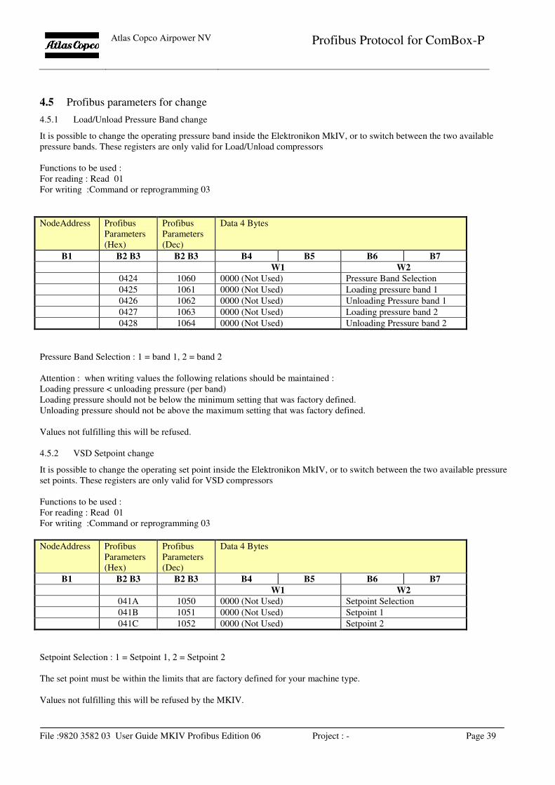
4.5 Profibus parameters for change
4.5.1 Load/Unload Pressure Band change
It is possible to change the operating pressure band inside the Elektronikon MkIV, or to switch between the two available
pressure bands. These registers are only valid for Load/Unload compressors
Functions to be used :
For reading : Read 01
For writing :Command or reprogramming 03
NodeAddress Profibus
Parameters
(Hex)
Profibus
Parameters
(Dec)
Data 4 Bytes
B1 B2 B3 B2 B3 B4 B5 B6 B7
W1 W2
0424 1060 0000 (Not Used) Pressure Band Selection
0425 1061 0000 (Not Used) Loading pressure band 1
0426 1062 0000 (Not Used) Unloading Pressure band 1
0427 1063 0000 (Not Used) Loading pressure band 2
0428 1064 0000 (Not Used) Unloading Pressure band 2
Pressure Band Selection : 1 = band 1, 2 = band 2
Attention : when writing values the following relations should be maintained :
Loading pressure < unloading pressure (per band)
Loading pressure should not be below the minimum setting that was factory defined.
Unloading pressure should not be above the maximum setting that was factory defined.
Values not fulfilling this will be refused.
4.5.2 VSD Setpoint change
It is possible to change the operating set point inside the Elektronikon MkIV, or to switch between the two available pressure
set points. These registers are only valid for VSD compressors
Functions to be used :
For reading : Read 01
For writing :Command or reprogramming 03
NodeAddress Profibus
Parameters
(Hex)
Profibus
Parameters
(Dec)
Data 4 Bytes
B1 B2 B3 B2 B3 B4 B5 B6 B7
W1 W2
041A 1050 0000 (Not Used) Setpoint Selection
041B 1051 0000 (Not Used) Setpoint 1
041C 1052 0000 (Not Used) Setpoint 2
Setpoint Selection : 1 = Setpoint 1, 2 = Setpoint 2
The set point must be within the limits that are factory defined for your machine type.
Values not fulfilling this will be refused by the MKIV.
Atlas Copco Airpower NV
Profibus Protocol for ComBox-P
File :9820 3582 03 User Guide MKIV Profibus Edition 06 Project : - Page 40
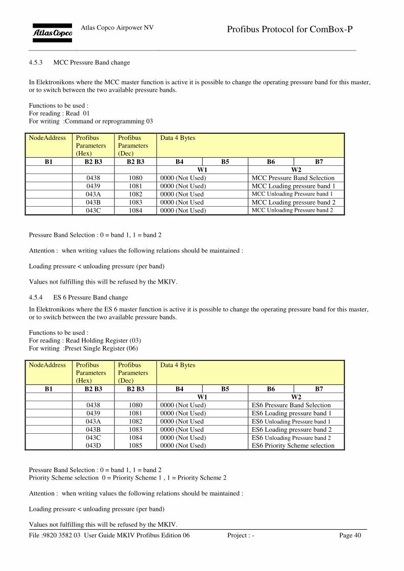
4.5.3 MCC Pressure Band change
In Elektronikons where the MCC master function is active it is possible to change the operating pressure band for this master,
or to switch between the two available pressure bands.
Functions to be used :
For reading : Read 01
For writing :Command or reprogramming 03
NodeAddress Profibus
Parameters
(Hex)
Profibus
Parameters
(Dec)
Data 4 Bytes
B1 B2 B3 B2 B3 B4 B5 B6 B7
W1 W2
0438 1080 0000 (Not Used) MCC Pressure Band Selection
0439 1081 0000 (Not Used) MCC Loading pressure band 1
043A 1082 0000 (Not Used MCC Unloading Pressure band 1
043B 1083 0000 (Not Used MCC Loading pressure band 2
043C 1084 0000 (Not Used) MCC Unloading Pressure band 2
Pressure Band Selection : 0 = band 1, 1 = band 2
Attention : when writing values the following relations should be maintained :
Loading pressure < unloading pressure (per band)
Values not fulfilling this will be refused by the MKIV.
4.5.4 ES 6 Pressure Band change
In Elektronikons where the ES 6 master function is active it is possible to change the operating pressure band for this master,
or to switch between the two available pressure bands.
Functions to be used :
For reading : Read Holding Register (03)
For writing :Preset Single Register (06)
NodeAddress Profibus
Parameters
(Hex)
Profibus
Parameters
(Dec)
Data 4 Bytes
B1 B2 B3 B2 B3 B4 B5 B6 B7
W1 W2
0438 1080 0000 (Not Used) ES6 Pressure Band Selection
0439 1081 0000 (Not Used) ES6 Loading pressure band 1
043A 1082 0000 (Not Used ES6 Unloading Pressure band 1
043B 1083 0000 (Not Used ES6 Loading pressure band 2
043C 1084 0000 (Not Used) ES6 Unloading Pressure band 2
043D 1085 0000 (Not Used) ES6 Priority Scheme selection
Pressure Band Selection : 0 = band 1, 1 = band 2
Priority Scheme selection 0 = Priority Scheme 1 , 1 = Priority Scheme 2
Attention : when writing values the following relations should be maintained :
Loading pressure < unloading pressure (per band)
Values not fulfilling this will be refused by the MKIV.
Atlas Copco Airpower NV
Profibus Protocol for ComBox-P
File :9820 3582 03 User Guide MKIV Profibus Edition 06 Project : - Page 41
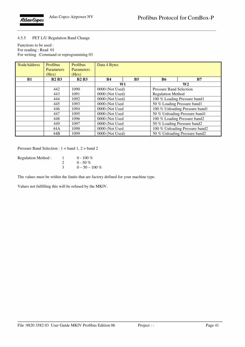
4.5.5 PET L/U Regulation Band Change
Functions to be used :
For reading : Read 01
For writing :Command or reprogramming 03
NodeAddress Profibus
Parameters
(Hex)
Profibus
Parameters
(Hex)
Data 4 Bytes
B1 B2 B3 B2 B3 B4 B5 B6 B7
W1 W2
442 1090 0000 (Not Used) Pressure Band Selection
443 1091 0000 (Not Used) Regulation Method
444 1092 0000 (Not Used) 100 % Loading Pressure band1
445 1093 0000 (Not Used 50 % Loading Pressure band1
446 1094 0000 (Not Used 100 % Unloading Pressure band1
447 1095 0000 (Not Used 50 % Unloading Pressure band1
448 1096 0000 (Not Used 100 % Loading Pressure band2
449 1097 0000 (Not Used 50 % Loading Pressure band2
44A 1098 0000 (Not Used 100 % Unloading Pressure band2
44B 1099 0000 (Not Used) 50 % Unloading Pressure band2
Pressure Band Selection : 1 = band 1, 2 = band 2
Regulation Method : 1 0 - 100 %
2 0 - 50 %
3 0 – 50 – 100 %
The values must be within the limits that are factory defined for your machine type.
Values not fulfilling this will be refused by the MKIV.
Atlas Copco Airpower NV
Profibus Protocol for ComBox-P
File :9820 3582 03 User Guide MKIV Profibus Edition 06 Project : - Page 42
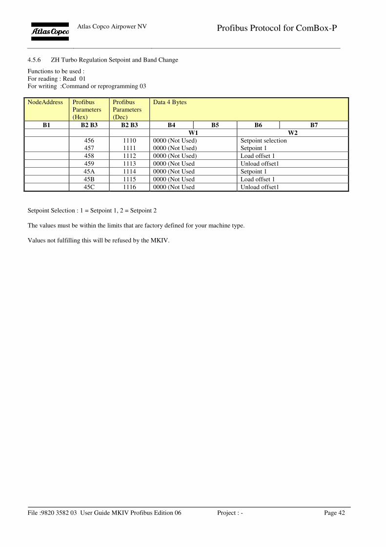
4.5.6 ZH Turbo Regulation Setpoint and Band Change
Functions to be used :
For reading : Read 01
For writing :Command or reprogramming 03
NodeAddress Profibus
Parameters
(Hex)
Profibus
Parameters
(Dec)
Data 4 Bytes
B1 B2 B3 B2 B3 B4 B5 B6 B7
W1 W2
456 1110 0000 (Not Used) Setpoint selection
457 1111 0000 (Not Used) Setpoint 1
458 1112 0000 (Not Used) Load offset 1
459 1113 0000 (Not Used Unload offset1
45A 1114 0000 (Not Used Setpoint 1
45B 1115 0000 (Not Used Load offset 1
45C 1116 0000 (Not Used Unload offset1
Setpoint Selection : 1 = Setpoint 1, 2 = Setpoint 2
The values must be within the limits that are factory defined for your machine type.
Values not fulfilling this will be refused by the MKIV.
Atlas Copco Airpower NV
Profibus Protocol for ComBox-P
File :9820 3582 03 User Guide MKIV Profibus Edition 06 Project : - Page 43
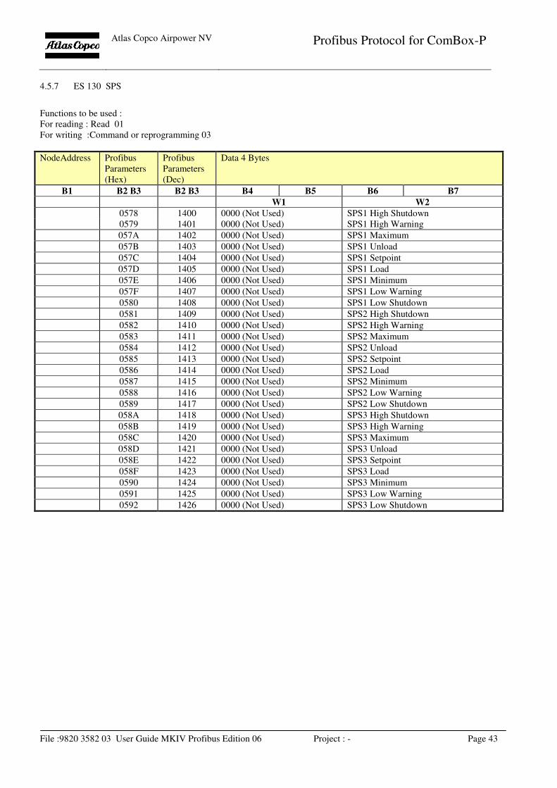
4.5.7 ES 130 SPS
Functions to be used :
For reading : Read 01
For writing :Command or reprogramming 03
NodeAddress Profibus
Parameters
(Hex)
Profibus
Parameters
(Dec)
Data 4 Bytes
B1 B2 B3 B2 B3 B4 B5 B6 B7
W1 W2
0578 1400 0000 (Not Used) SPS1 High Shutdown
0579 1401 0000 (Not Used) SPS1 High Warning
057A 1402 0000 (Not Used) SPS1 Maximum
057B 1403 0000 (Not Used) SPS1 Unload
057C 1404 0000 (Not Used) SPS1 Setpoint
057D 1405 0000 (Not Used) SPS1 Load
057E 1406 0000 (Not Used) SPS1 Minimum
057F 1407 0000 (Not Used) SPS1 Low Warning
0580 1408 0000 (Not Used) SPS1 Low Shutdown
0581 1409 0000 (Not Used) SPS2 High Shutdown
0582 1410 0000 (Not Used) SPS2 High Warning
0583 1411 0000 (Not Used) SPS2 Maximum
0584 1412 0000 (Not Used) SPS2 Unload
0585 1413 0000 (Not Used) SPS2 Setpoint
0586 1414 0000 (Not Used) SPS2 Load
0587 1415 0000 (Not Used) SPS2 Minimum
0588 1416 0000 (Not Used) SPS2 Low Warning
0589 1417 0000 (Not Used) SPS2 Low Shutdown
058A 1418 0000 (Not Used) SPS3 High Shutdown
058B 1419 0000 (Not Used) SPS3 High Warning
058C 1420 0000 (Not Used) SPS3 Maximum
058D 1421 0000 (Not Used) SPS3 Unload
058E 1422 0000 (Not Used) SPS3 Setpoint
058F 1423 0000 (Not Used) SPS3 Load
0590 1424 0000 (Not Used) SPS3 Minimum
0591 1425 0000 (Not Used) SPS3 Low Warning
0592 1426 0000 (Not Used) SPS3 Low Shutdown
Atlas Copco Airpower NV
Profibus Protocol for ComBox-P
File :9820 3582 03 User Guide MKIV Profibus Edition 06 Project : - Page 44
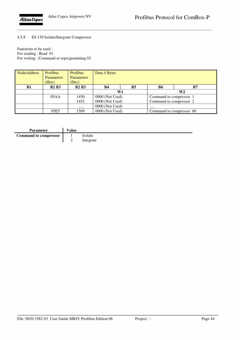
4.5.8 ES 130 Isolate/Integrate Compressor
Functions to be used :
For reading : Read 01
For writing :Command or reprogramming 03
NodeAddress Profibus
Parameters
(Hex)
Profibus
Parameters
(Dec)
Data 4 Bytes
B1 B2 B3 B2 B3 B4 B5 B6 B7
W1 W2
05AA 1450 0000 (Not Used) Command to compressor 1
1452 0000 (Not Used) Command to compressor 2
….. 0000 (Not Used) …..
05E5 1509 0000 (Not Used) Command to compressor 60
Parameter Value
Command to compressor 1
2
Isolate
Integrate
Atlas Copco Airpower NV
Profibus Protocol for ComBox-P
File :9820 3582 03 User Guide MKIV Profibus Edition 06 Project : - Page 45
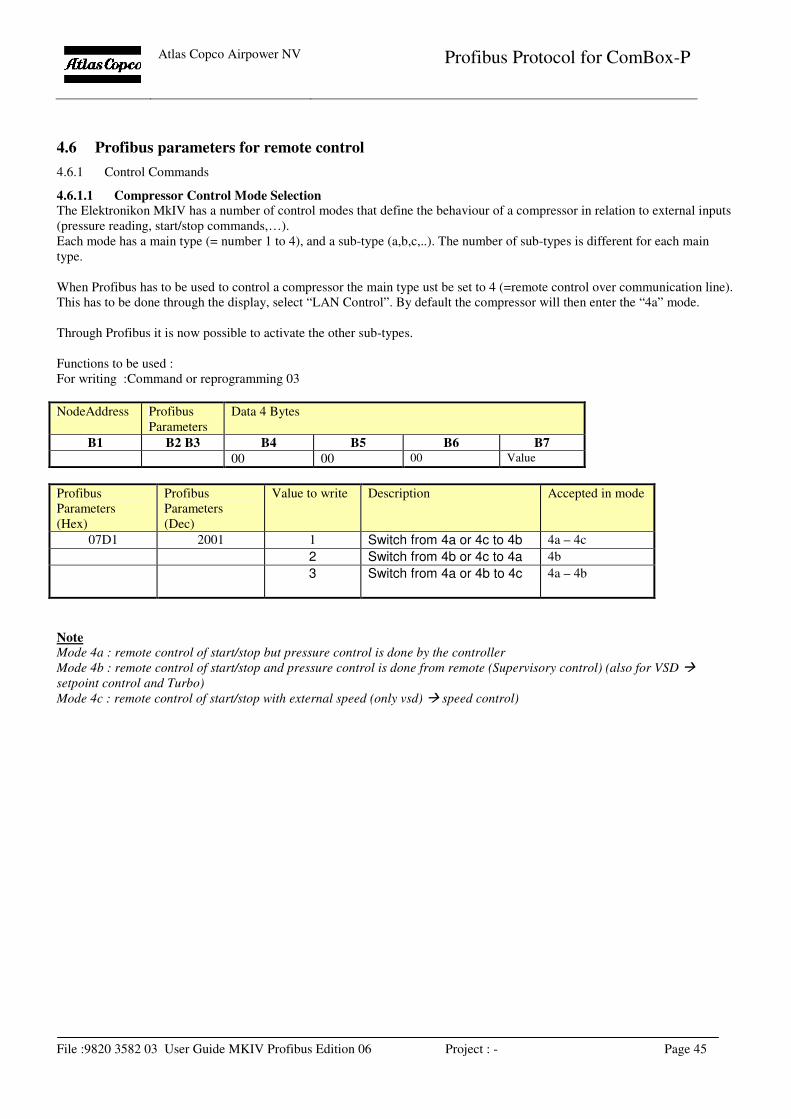
4.6 Profibus parameters for remote control
4.6.1 Control Commands
4.6.1.1 Compressor Control Mode Selection The Elektronikon MkIV has a number of control modes that define the behaviour of a compressor in relation to external inputs
(pressure reading, start/stop commands,…).
Each mode has a main type (= number 1 to 4), and a sub-type (a,b,c,..). The number of sub-types is different for each main
type.
When Profibus has to be used to control a compressor the main type ust be set to 4 (=remote control over communication line).
This has to be done through the display, select “LAN Control”. By default the compressor will then enter the “4a” mode.
Through Profibus it is now possible to activate the other sub-types.
Functions to be used :
For writing :Command or reprogramming 03
NodeAddress Profibus
Parameters
Data 4 Bytes
B1 B2 B3 B4 B5 B6 B7
00 00 00 Value
Profibus
Parameters
(Hex)
Profibus
Parameters
(Dec)
Value to write Description Accepted in mode
07D1 2001 1 Switch from 4a or 4c to 4b 4a – 4c
2 Switch from 4b or 4c to 4a 4b
3 Switch from 4a or 4b to 4c 4a – 4b
Note Mode 4a : remote control of start/stop but pressure control is done by the controller
Mode 4b : remote control of start/stop and pressure control is done from remote (Supervisory control) (also for VSD �
setpoint control and Turbo)
Mode 4c : remote control of start/stop with external speed (only vsd) � speed control)
Atlas Copco Airpower NV
Profibus Protocol for ComBox-P
File :9820 3582 03 User Guide MKIV Profibus Edition 06 Project : - Page 46
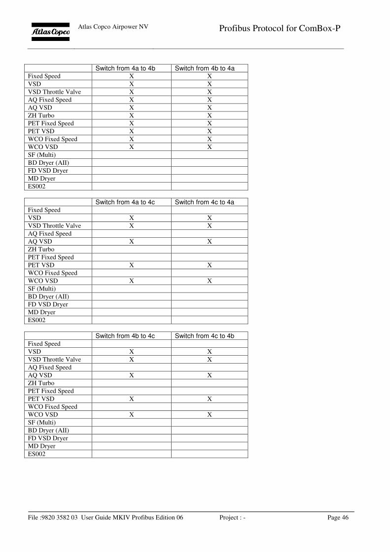
Switch from 4a to 4b Switch from 4b to 4a
Fixed Speed X X
VSD X X
VSD Throttle Valve X X
AQ Fixed Speed X X
AQ VSD X X
ZH Turbo X X
PET Fixed Speed X X
PET VSD X X
WCO Fixed Speed X X
WCO VSD X X
SF (Multi)
BD Dryer (AII)
FD VSD Dryer
MD Dryer
ES002
Switch from 4a to 4c Switch from 4c to 4a
Fixed Speed
VSD X X
VSD Throttle Valve X X
AQ Fixed Speed
AQ VSD X X
ZH Turbo
PET Fixed Speed
PET VSD X X
WCO Fixed Speed
WCO VSD X X
SF (Multi)
BD Dryer (AII)
FD VSD Dryer
MD Dryer
ES002
Switch from 4b to 4c Switch from 4c to 4b
Fixed Speed
VSD X X
VSD Throttle Valve X X
AQ Fixed Speed
AQ VSD X X
ZH Turbo
PET Fixed Speed
PET VSD X X
WCO Fixed Speed
WCO VSD X X
SF (Multi)
BD Dryer (AII)
FD VSD Dryer
MD Dryer
ES002
Atlas Copco Airpower NV
Profibus Protocol for ComBox-P
File :9820 3582 03 User Guide MKIV Profibus Edition 06 Project : - Page 47
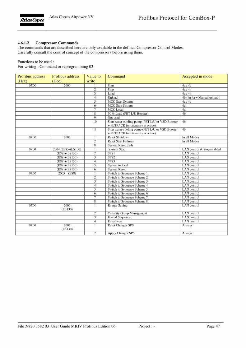
4.6.1.2 Compressor Commands
The commands that are described here are only available in the defined Compressor Control Modes.
Carefully consult the control concept of the compressors before using them.
Functions to be used :
For writing :Command or reprogramming 03
Profibus address
(Hex)
Profibus address
(Dec)
Value to
write
Command Accepted in mode
07D0 2000 1 Start 4a / 4b
2 Stop 4a / 4b
3 Load 4a / 4b
4 Unload 4b ( in 4a = Manual unload )
5 MCC Start System 4a / 4d
6 MCC Stop System 4d
7 MCC Local 4d
8 50 % Load (PET L/U Booster) 4b
9 Not used
10 Start water-cooling pump (PET L/U or VSD Booster
+ PETPACK functionality is active)
4b
11 Stop water-cooling pump (PET L/U or VSD Booster
+ PETPACK functionality is active)
4b
07D3 2003 1 Reset Shutdown In all Modes
2 Reset Start Failures In all Modes
8 System Reset ES4i
07D4 2004 (ES8)+(ES130) 1 System Stop LAN control & Stop enabled
(ES8)+(ES130) 2 SPS1 LAN control
(ES8)+(ES130) 3 SPS2 LAN control
(ES8)+(ES130) 4 SPS3 LAN control
(ES8)+(ES130) 5 System to local LAN control
(ES8)+(ES130) 6 System Reset LAN control
07D5 2005 (ES8) 1 Switch to Sequence Scheme 1 LAN control
2 Switch to Sequence Scheme 2 LAN control
3 Switch to Sequence Scheme 3 LAN control
4 Switch to Sequence Scheme 4 LAN control
5 Switch to Sequence Scheme 5 LAN control
6 Switch to Sequence Scheme 6 LAN control
7 Switch to Sequence Scheme 7 LAN control
8 Switch to Sequence Scheme 8 LAN control
07D6
2006
(ES130)
1 Energy Saving LAN control
2 Capacity Group Management LAN control
3 Forced Sequence LAN control
4 Equal wear LAN control
07D7
2007
(ES130)
1 Reset Changes SPS Always
2 Apply Changes SPS Always
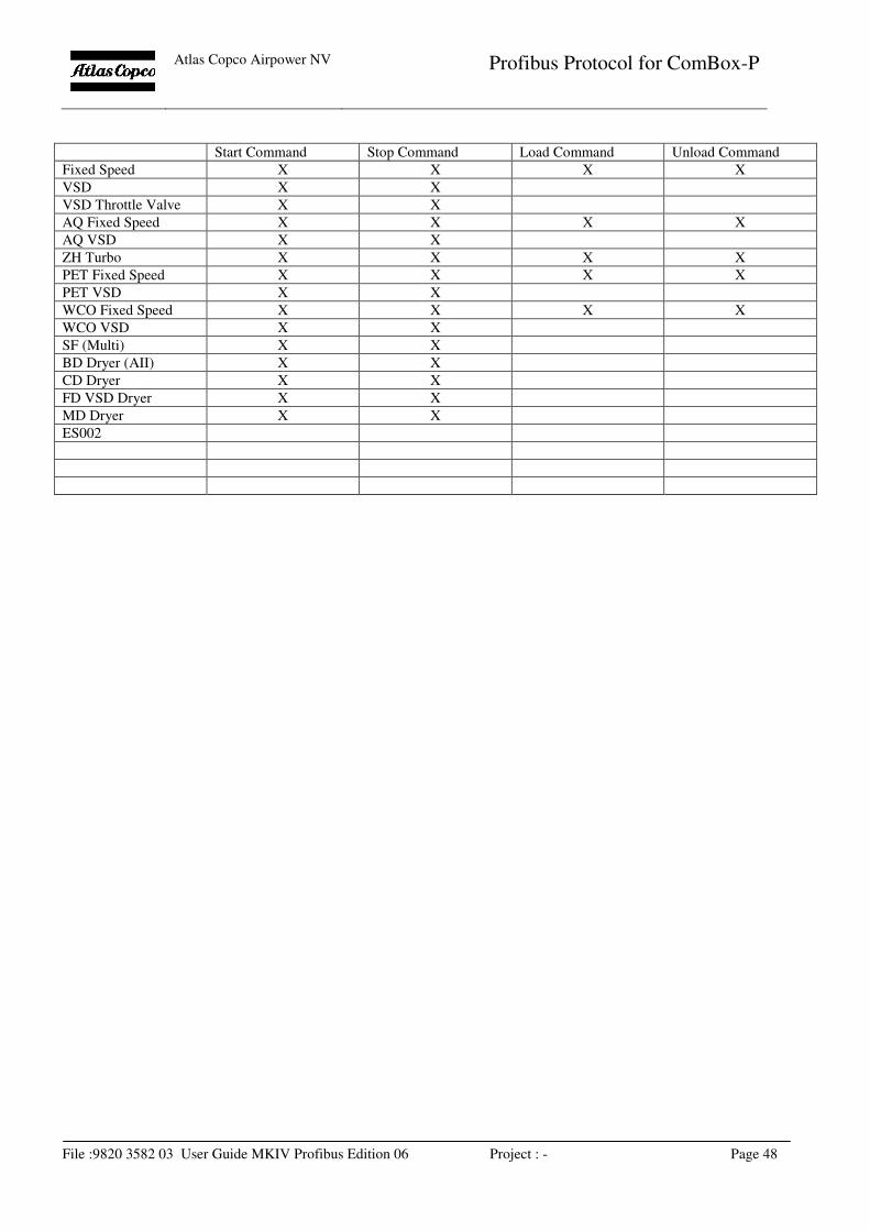
Atlas Copco Airpower NV
Profibus Protocol for ComBox-P
File :9820 3582 03 User Guide MKIV Profibus Edition 06 Project : - Page 48
Start Command Stop Command Load Command Unload Command
Fixed Speed X X X X
VSD X X
VSD Throttle Valve X X
AQ Fixed Speed X X X X
AQ VSD X X
ZH Turbo X X X X
PET Fixed Speed X X X X
PET VSD X X
WCO Fixed Speed X X X X
WCO VSD X X
SF (Multi) X X
BD Dryer (AII) X X
CD Dryer X X
FD VSD Dryer X X
MD Dryer X X
ES002
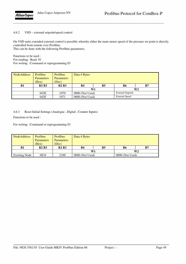
Atlas Copco Airpower NV
Profibus Protocol for ComBox-P
File :9820 3582 03 User Guide MKIV Profibus Edition 06 Project : - Page 49
4.6.2 VSD – external setpoint/speed control
On VSD units extended external control is possible whereby either the main motor speed of the pressure set point is directly
controlled from remote over Profibus.
This can be done with the following Profibus parameters.
Functions to be used :
For reading : Read 01
For writing :Command or reprogramming 03
NodeAddress Profibus
Parameters
(Hex)
Profibus
Parameters
(Dec)
Data 4 Bytes
B1 B2 B3 B2 B3 B4 B5 B6 B7
W1 W2
042E 1070 0000 (Not Used) External Setpoint
042F 1071 0000 (Not Used) External Speed
4.6.3 Reset Initial Settings (Analogue , Digital , Counter Inputs)
Functions to be used :
For writing :Command or reprogramming 03
NodeAddress Profibus
Parameters
(Hex)
Profibus
Parameters
(Dec)
Data 4 Bytes
B1 B2 B3 B2 B3 B4 B5 B6 B7
W1 W2
Existing Node 0834 2100 0000 (Not Used) 0000 (Not Used)
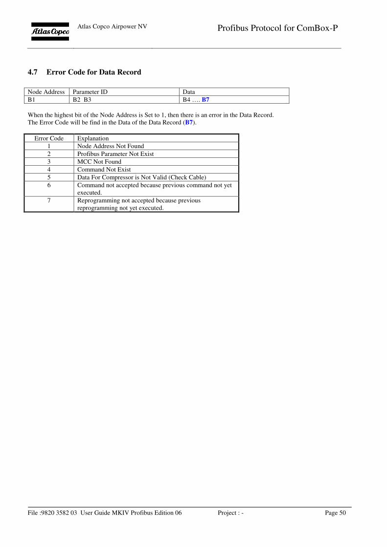
Atlas Copco Airpower NV
Profibus Protocol for ComBox-P
File :9820 3582 03 User Guide MKIV Profibus Edition 06 Project : - Page 50
4.7 Error Code for Data Record
Node Address Parameter ID Data
B1 B2 B3 B4 …. B7
When the highest bit of the Node Address is Set to 1, then there is an error in the Data Record.
The Error Code will be find in the Data of the Data Record (B7).
Error Code Explanation
1 Node Address Not Found
2 Profibus Parameter Not Exist
3 MCC Not Found
4 Command Not Exist
5 Data For Compressor is Not Valid (Check Cable)
6 Command not accepted because previous command not yet
executed.
7 Reprogramming not accepted because previous
reprogramming not yet executed.
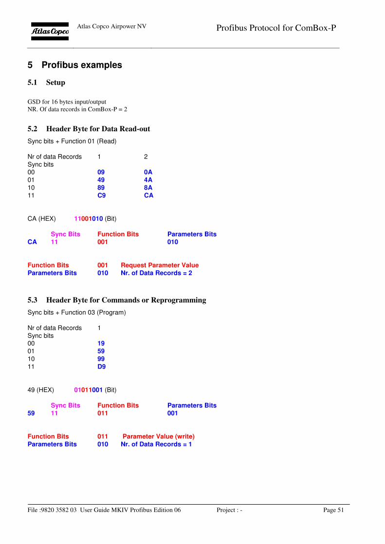
Atlas Copco Airpower NV
Profibus Protocol for ComBox-P
File :9820 3582 03 User Guide MKIV Profibus Edition 06 Project : - Page 51
5 Profibus examples
5.1 Setup
GSD for 16 bytes input/output
NR. Of data records in ComBox-P = 2
5.2 Header Byte for Data Read-out
Sync bits + Function 01 (Read)
Nr of data Records 1 2
Sync bits 00 09 0A
01 49 4A
10 89 8A
11 C9 CA
CA (HEX) 11001010 (Bit)
Sync Bits Function Bits Parameters Bits
CA 11 001 010
Function Bits 001 Request Parameter Value
Parameters Bits 010 Nr. of Data Records = 2
5.3 Header Byte for Commands or Reprogramming
Sync bits + Function 03 (Program)
Nr of data Records 1
Sync bits 00 19
01 59
10 99
11 D9
49 (HEX) 01011001 (Bit)
Sync Bits Function Bits Parameters Bits
59 11 011 001
Function Bits 011 Parameter Value (write)
Parameters Bits 010 Nr. of Data Records = 1
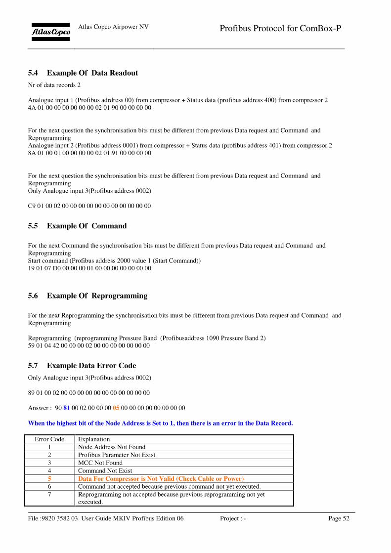
Atlas Copco Airpower NV
Profibus Protocol for ComBox-P
File :9820 3582 03 User Guide MKIV Profibus Edition 06 Project : - Page 52
5.4 Example Of Data Readout
Nr of data records 2
Analogue input 1 (Profibus adrdress 00) from compressor + Status data (profibus address 400) from compressor 2
4A 01 00 00 00 00 00 00 02 01 90 00 00 00 00
For the next question the synchronisation bits must be different from previous Data request and Command and
Reprogramming
Analogue input 2 (Profibus address 0001) from compressor + Status data (profibus address 401) from compressor 2
8A 01 00 01 00 00 00 00 02 01 91 00 00 00 00
For the next question the synchronisation bits must be different from previous Data request and Command and
Reprogramming
Only Analogue input 3(Profibus address 0002)
C9 01 00 02 00 00 00 00 00 00 00 00 00 00 00
5.5 Example Of Command
For the next Command the synchronisation bits must be different from previous Data request and Command and
Reprogramming
Start command (Profibus address 2000 value 1 (Start Command))
19 01 07 D0 00 00 00 01 00 00 00 00 00 00 00
5.6 Example Of Reprogramming
For the next Reprogramming the synchronisation bits must be different from previous Data request and Command and
Reprogramming
Reprogramming (reprogramming Pressure Band (Profibusaddress 1090 Pressure Band 2)
59 01 04 42 00 00 00 02 00 00 00 00 00 00 00
5.7 Example Data Error Code
Only Analogue input 3(Profibus address 0002)
89 01 00 02 00 00 00 00 00 00 00 00 00 00 00
Answer : 90 81 00 02 00 00 00 05 00 00 00 00 00 00 00 00
When the highest bit of the Node Address is Set to 1, then there is an error in the Data Record.
Error Code Explanation
1 Node Address Not Found
2 Profibus Parameter Not Exist
3 MCC Not Found
4 Command Not Exist
5 Data For Compressor is Not Valid (Check Cable or Power)
6 Command not accepted because previous command not yet executed.
7 Reprogramming not accepted because previous reprogramming not yet
executed.
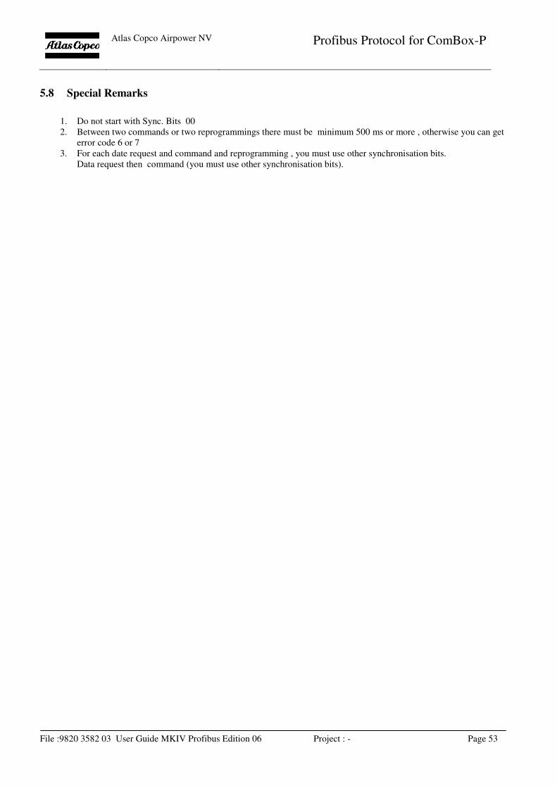
Atlas Copco Airpower NV
Profibus Protocol for ComBox-P
File :9820 3582 03 User Guide MKIV Profibus Edition 06 Project : - Page 53
5.8 Special Remarks
1. Do not start with Sync. Bits 00
2. Between two commands or two reprogrammings there must be minimum 500 ms or more , otherwise you can get
error code 6 or 7
3. For each date request and command and reprogramming , you must use other synchronisation bits.
Data request then command (you must use other synchronisation bits).
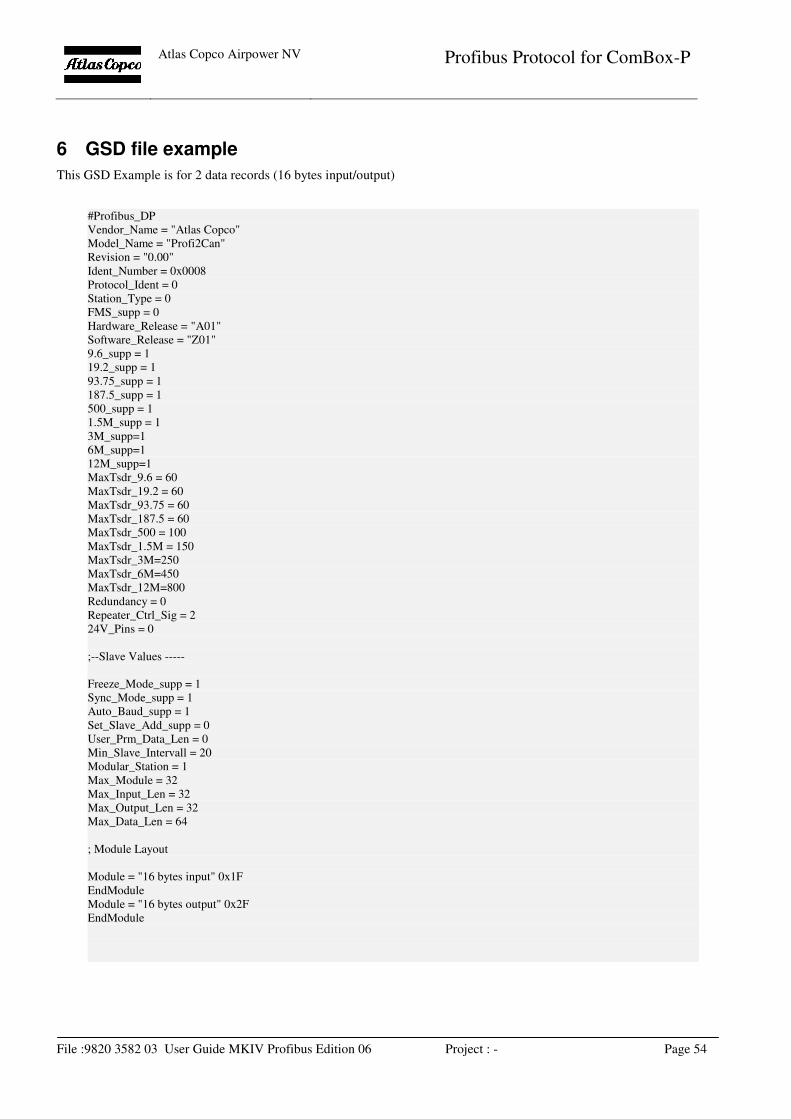
Atlas Copco Airpower NV
Profibus Protocol for ComBox-P
File :9820 3582 03 User Guide MKIV Profibus Edition 06 Project : - Page 54
6 GSD file example
This GSD Example is for 2 data records (16 bytes input/output)
#Profibus_DP
Vendor_Name = "Atlas Copco"
Model_Name = "Profi2Can"
Revision = "0.00"
Ident_Number = 0x0008
Protocol_Ident = 0
Station_Type = 0
FMS_supp = 0
Hardware_Release = "A01"
Software_Release = "Z01"
9.6_supp = 1
19.2_supp = 1
93.75_supp = 1
187.5_supp = 1
500_supp = 1
1.5M_supp = 1
3M_supp=1
6M_supp=1
12M_supp=1
MaxTsdr_9.6 = 60
MaxTsdr_19.2 = 60
MaxTsdr_93.75 = 60
MaxTsdr_187.5 = 60
MaxTsdr_500 = 100
MaxTsdr_1.5M = 150
MaxTsdr_3M=250
MaxTsdr_6M=450
MaxTsdr_12M=800
Redundancy = 0
Repeater_Ctrl_Sig = 2
24V_Pins = 0
;--Slave Values -----
Freeze_Mode_supp = 1
Sync_Mode_supp = 1
Auto_Baud_supp = 1
Set_Slave_Add_supp = 0
User_Prm_Data_Len = 0
Min_Slave_Intervall = 20
Modular_Station = 1
Max_Module = 32
Max_Input_Len = 32
Max_Output_Len = 32
Max_Data_Len = 64
; Module Layout
Module = "16 bytes input" 0x1F
EndModule
Module = "16 bytes output" 0x2F
EndModule
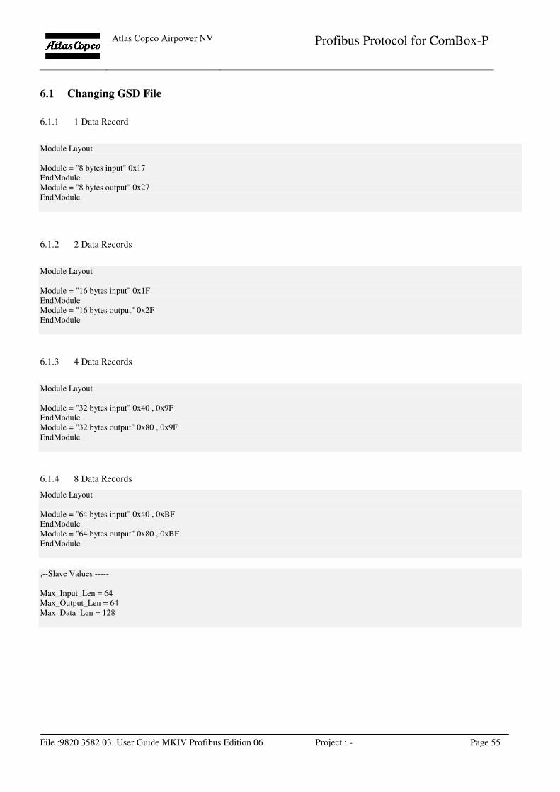
Atlas Copco Airpower NV
Profibus Protocol for ComBox-P
File :9820 3582 03 User Guide MKIV Profibus Edition 06 Project : - Page 55
6.1 Changing GSD File
6.1.1 1 Data Record
Module Layout
Module = "8 bytes input" 0x17
EndModule
Module = "8 bytes output" 0x27
EndModule
6.1.2 2 Data Records
Module Layout
Module = "16 bytes input" 0x1F
EndModule
Module = "16 bytes output" 0x2F
EndModule
6.1.3 4 Data Records
Module Layout
Module = "32 bytes input" 0x40 , 0x9F
EndModule
Module = "32 bytes output" 0x80 , 0x9F
EndModule
6.1.4 8 Data Records
Module Layout
Module = "64 bytes input" 0x40 , 0xBF
EndModule
Module = "64 bytes output" 0x80 , 0xBF
EndModule
;--Slave Values -----
Max_Input_Len = 64
Max_Output_Len = 64
Max_Data_Len = 128
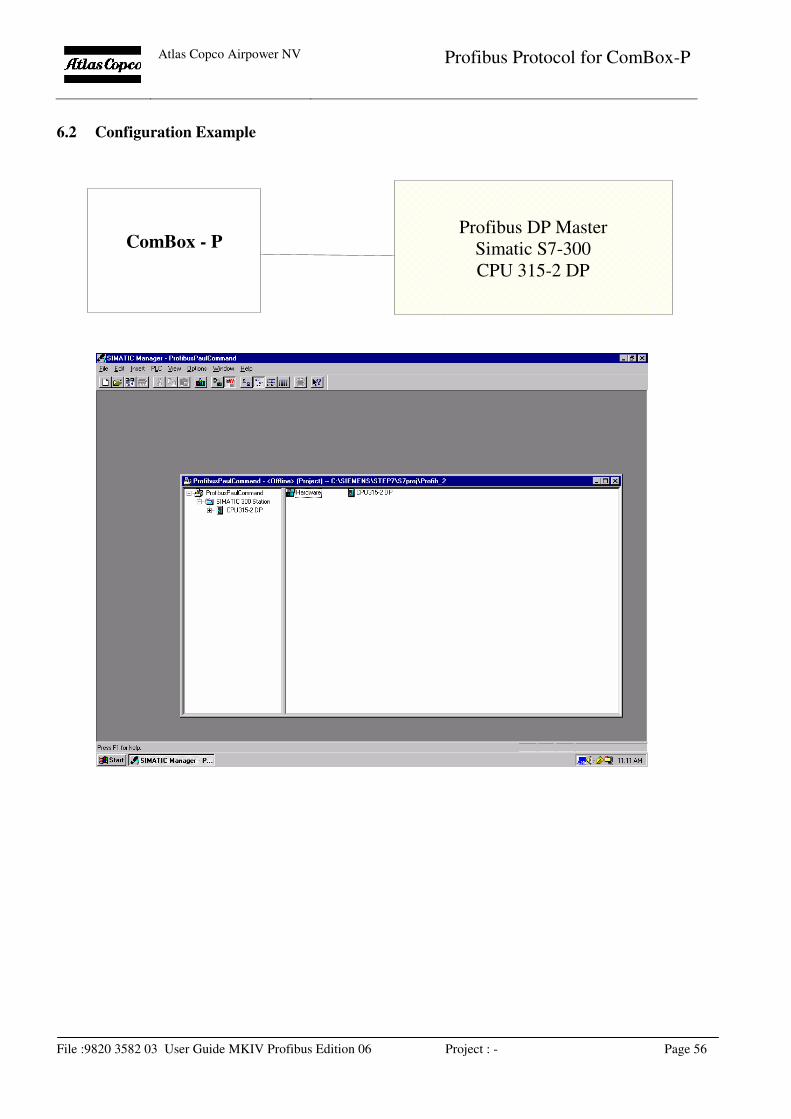
Atlas Copco Airpower NV
Profibus Protocol for ComBox-P
File :9820 3582 03 User Guide MKIV Profibus Edition 06 Project : - Page 56
6.2 Configuration Example
ComBox - P
Profibus DP Master
Simatic S7-300
CPU 315-2 DP
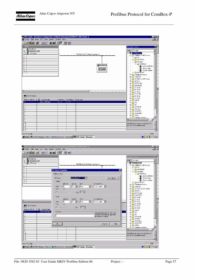
Atlas Copco Airpower NV
Profibus Protocol for ComBox-P
File :9820 3582 03 User Guide MKIV Profibus Edition 06 Project : - Page 57