Embed Size (px)
Citation preview
INSTALLATION INSTRUCTIONS FOR PART 99-7898/AT-807HD/AW-807HD
1-800-221-0932 www.metraonline.com© COPYRIGHT 2004-2008 METRA ELECTRONICS CORPORATION
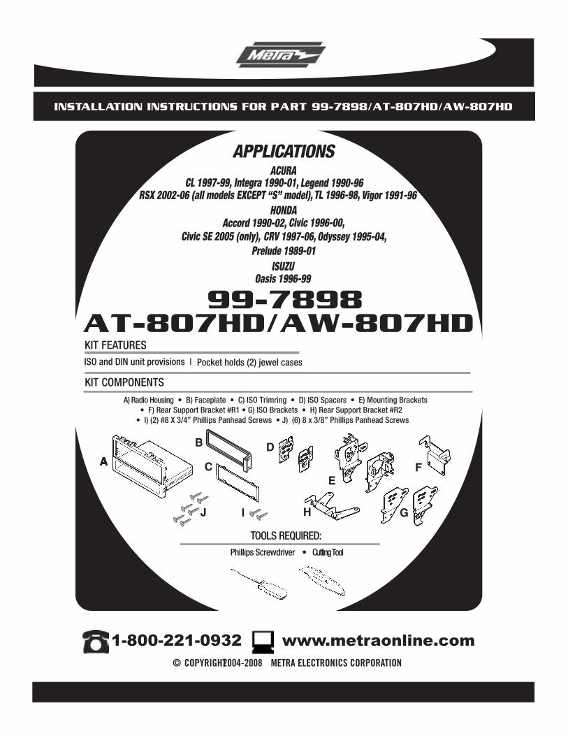
KIT FEATURESISO and DIN unit provisions |
A) Radio Housing • B) Faceplate • C) ISO Trimring • D) ISO Spacers • E) Mounting Brackets • F) Rear Support Bracket #R1 • G) ISO Brackets • H) Rear Support Bracket #R2 • I) (2) #8 X 3/4” Phillips Panhead Screws • J) (6) 8 x 3/8” Phillips Panhead Screws
KIT COMPONENTS
TOOLS REQUIRED:
99-7898
A
APPLICATIONS
Phillips Screwdriver • Cutting Tool
AT-807HD/AW-807HDPocket holds (2) jewel cases
AAAA
B
CD
EF
GHJ
CL 1997-99, Integra 1990-01, Legend 1990-96 RSX 2002-06 (all models EXCEPT “S” model), TL 1996-98, Vigor 1991-96
ACURA
HONDAAccord 1990-02, Civic 1996-00,
Civic SE 2005 (only), CRV 1997-06, Odyssey 1995-04,Prelude 1989-01
Oasis 1996-99ISUZU
I

99-7898/AT-807HD/AW-807HD
T OFABLE CONTENTS
CL 1997-99 . . . . . . . . . . . . . . . . . . . . . . . . . . . . . . . . . . . . . . . . . . 1
Kit Assembly . . . . . . . . . . . . . . . . . . . . . . . . . . . . . . . . . . . . 11-12
Final
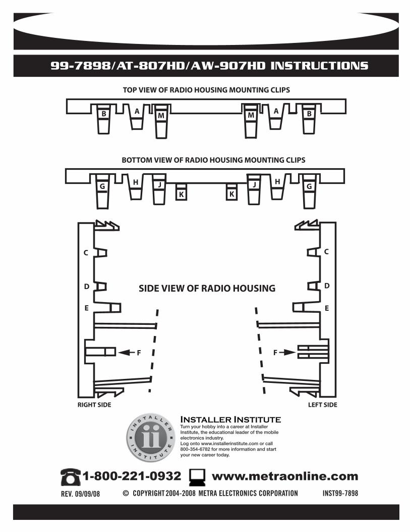
See back page for specific clip letter locations etched on Radio Housings. RADIO HOUSING MOUNTING CLIP LOCATIONS FOR CUTTING
Assembly . . . . . . . . . . . . . . . . . . . . . . . . . . . . . . . . . . . . . .13
Integra 1990-93 . . . . . . . . . . . . . . . . . . . . . . . . . . . . . . . . . . . . . . 1Integra 1994-01. . . . . . . . . . . . . . . . . . . . . . . . . . . . . . . . . . . . . . . 2Legend 1990-96 . . . . . . . . . . . . . . . . . . . . . . . . . . . . . . . . . . . . . . 2RSX 2002-06 (all models EXCEPT “S” model) .. . . . . . . . . . . . . . . . 3TL 1996-98 . . . . . . . . . . . . . . . . . . . . . . . . . . . . . . . . . . . . . . . . . . 3Vigor 1991-96 . . . . . . . . . . . . . . . . . . . . . . . . . . . . . . . . . . . . . . . . 4
ACURA
Accord 1990-93. . . . . . . . . . . . . . . . . . . . . . . . . . . . . . . . . . . . . . . 4Accord 1994-97 . . . . . . . . . . . . . . . . . . . . . . . . . . . . . . . . . . . . . . 5Accord 1998-02 . . . . . . . . . . . . . . . . . . . . . . . . . . . . . . . . . . . . . . . 5Civic 1996-98. . . . . . . . . . . . . . . . . . . . . . . . . . . . . . . . . . . . . . . . . 6Civic 1999-00 . . . . . . . . . . . . . . . . . . . . . . . . . . . . . . . . . . . . . . . . . 6Civic SE 2005 (only) . . . . . . . . . . . . . . . . . . . . . . . . . . . . . . . . . . . 7CRV 1997-01 . . . . . . . . . . . . . . . . . . . . . . . . . . . . . . . . . . . . . . . . . 8
HONDA
CRV 2002-06 . . . . . . . . . . . . . . . . . . . . . . . . . . . . . . . . . . . . . . . . 8Odyssey 1995-98 . . . . . . . . . . . . . . . . . . . . . . . . . . . . . . . . . . . . . . 9Odyssey 1999-04 . . . . . . . . . . . . . . . . . . . . . . . . . . . . . . . . . . . . . 9Prelude 1989-91 . . . . . . . . . . . . . . . . . . . . . . . . . . . . . . . . . . . . . .10Prelude 1992-96 . . . . . . . . . . . . . . . . . . . . . . . . . . . . . . . . . . . . . .10 Prelude 1997-01 . . . . . . . . . . . . . . . . . . . . . . . . . . . . . . . . . . . . . . 11
Oasis 1996-99 . . . . . . . . . . . . . . . . . . . . . . . . . . . . . . . . . . . . . . . . 9ISUZU
99-7898/AT-807HD/AW-807HD
1
1
ACURA CL 1997-99
DASH DISASSEMBLY
A
B
B
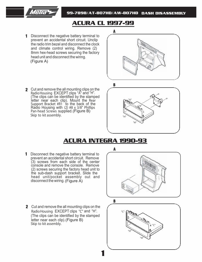
ADisconnect the negative battery terminal to prevent an accidental short circuit. Remove (3) screws from each side of the center console and remove the console. Remove (2) screws securing the factory head unit to the sub-dash support bracket. Slide the head unit/pocket assembly out and disconnect the wiring.
Cut and remove the all mounting clips on the Radio Housing EXCEPT clips "C" and "H".(The clips can be identified by the stamped letter near each clip).Skip to kit assembly.
ACURA INTEGRA 1990-93
(Figure A)
(Figure B)
2
1
2
"H"
"H"
"C"
"C"
(Figure A)
Disconnect the negative battery terminal to prevent an accidental short circuit. Unclip the radio trim bezel and disconnect the clock and climate control wiring. Remove (2) 8mm hex-head screws securing the factory head unit and disconnect the wiring.
"A"
"H"
"H"
"A"
Cut and remove the all mounting clips on the Radio Housing EXCEPT clips "A" and "H".(The clips can be identified by the stamped letter near each clip). Mount the RearSupport Bracket #R1 to the back of the Radio Housing with (2) #8 x 3/8" Phillips Pan-head Screws supplied.Skip to kit assembly.
(Figure B)

99-7898/AT-807HD/AW-807HD
2
1
ACURA INTEGRA 1994-01
DASH DISASSEMBLY
A
B
B
A
ACURA LEGEND 1990-96
2
1
2
"H"
"H"
"C"
"C"
Disconnect the negative battery terminal to prevent an accidental short circuit. Remove the cover cap located under the emergency brake and remove (2) screws exposed.Remove (2) screws from the rear corners of the lower dash trim bezel and remove.Remove the ashtray and (2) screws exposed. Unsnap the ashtray housing and disconnect the cigarette lighter harness.Remove the gear shifter knob and unsnap the shifter trim. Remove (2) screws below the radio opening and remove the upper dash trim bezel. Remove (2) 8mm screws securing the factory head unit and disconnect the wiring.
Cut and remove the all mounting clips on the Radio Housing EXCEPT clips "C"and "H".(The clips can be identified by the stamped letter near each clip).Skip to final assembly.
(Figure A)
(Figure B)
"E"
"E"
"J"
"J"
Disconnect the negative battery terminal to prevent an accidental short circuit. Remove (2) screws below the ashtray. Unclip the dash trim bezel. Disconnect the cigarette lighter wiring and remove the bezel.Remove (2) bolts securing the rear of the factory head unit and disconnect the wiring.
Cut and remove the all mounting clips on the Radio Housing EXCEPT clips "E" and "J".(The clips can be identified by the stamped letter near each clip).Skip to final assembly.
(Figure A)
(Figure B)
99-7898/AT-807HD/AW-807HD
1
ACURA RSX 2002-06
DASH DISASSEMBLY
A
B
B
A
ACURA TL 1996-98
(Figure A)
(Figure B)
2
1
2
"J"
"J"
"B"
"B"
"K""K"
Disconnect the negative battery terminal to prevent an accidental short circuit. Unclip the lower dash panel (containing the power outlet) and remove the panel. Reach into the opening and remove (2) Phillips screws from the base of the factory head unit. Slide the factory head unit (w/ bracket assembly) from the dash and disconnect the wiring. Remove (4) Phillips screws securing the factory head unit to the bracket assembly and remove the unit. (If a factory pocket is present, remove (4) Phillips screws securing the pocket to the bracket assembly and remove).
Cut and remove the all mounting clips on the Radio Housing EXCEPT clips "J". (The clips can be identified by the stamped letter near each clip). Mount the Rear Support Bracket #R2 to the back of the Radio Housing with (2) #8 x 3/8" Phillips Pan-head Screws supplied.Skip to kit assembly.
Disconnect the negative battery terminal to prevent an accidental short circuit. Using a small screwdriver, unclip the perimeter of the radio trim bezel. Disconnect the climate control and rear defroster wiring and remove the bezel.Remove (4) Phillips screws securing the factory head unit/trim bezel assembly. Loosen (2) Phillips screws securing the back of the head unit to the metal housing and slide the unit out.(It is NOT necessary to remove the screws securing the metal housing to the bezel).Disconnect the wiring.
Cut and remove the all mounting clips on the Radio Housing EXCEPT clips "B" and "K".(The clips can be identified by the stamped letter near each clip).Skip to kit assembly.
(Figure A)
(Figure B)
3
99-7898/AT-807HD/AW-807HD
4
1
ACURA VIGOR 1991-96
DASH DISASSEMBLY
A
B
B
A
HONDA ACCORD 1990-93
(Figure A)
(Figure B)
2
1
2
(Figure B)
(Figure A)
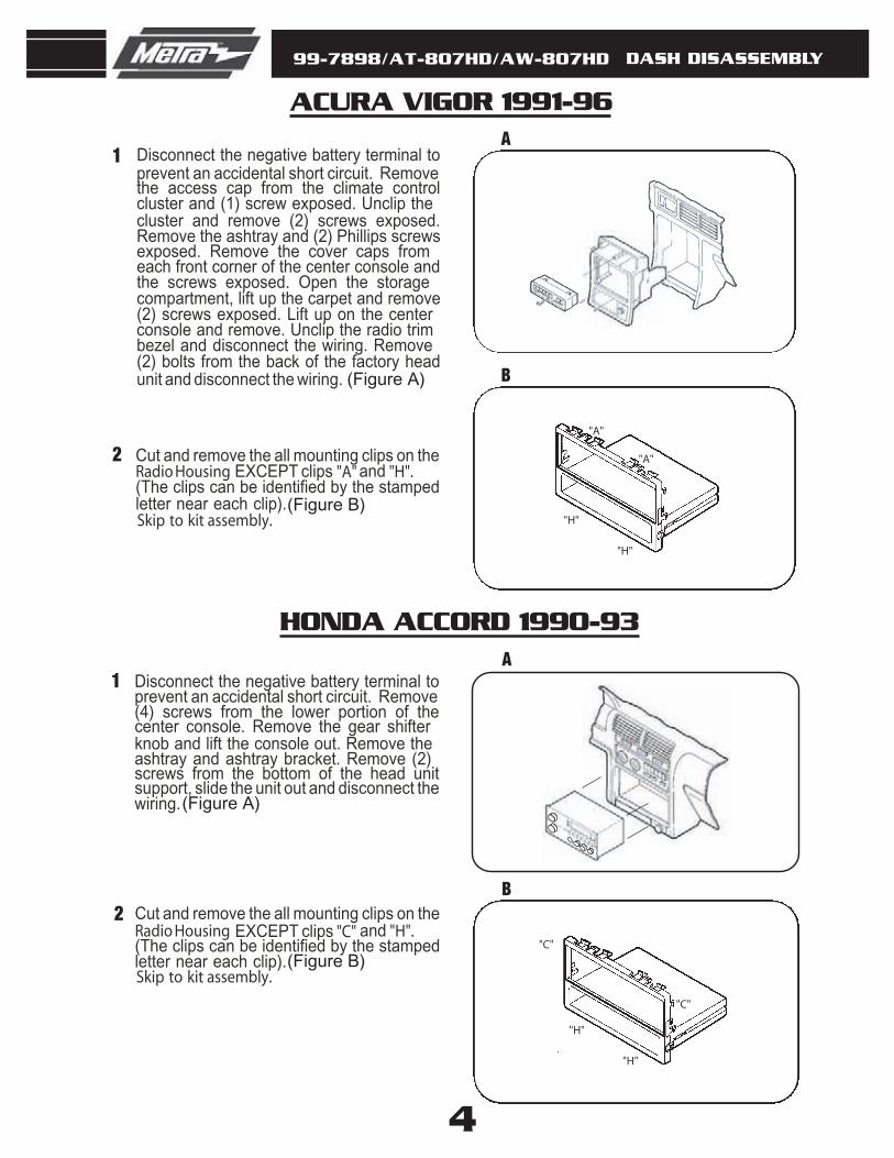
Disconnect the negative battery terminal to prevent an accidental short circuit. Remove the access cap from the climate control cluster and (1) screw exposed. Unclip the cluster and remove (2) screws exposed.Remove the ashtray and (2) Phillips screws exposed. Remove the cover caps from each front corner of the center console and the screws exposed. Open the storage compartment, lift up the carpet and remove (2) screws exposed. Lift up on the center console and remove. Unclip the radio trim bezel and disconnect the wiring. Remove (2) bolts from the back of the factory head unit and disconnect the wiring.
Cut and remove the all mounting clips on the Radio Housing EXCEPT clips "A" and "H".(The clips can be identified by the stamped letter near each clip).Skip to kit assembly.
Disconnect the negative battery terminal to prevent an accidental short circuit. Remove (4) screws from the lower portion of the center console. Remove the gear shifter knob and lift the console out. Remove the ashtray and ashtray bracket. Remove (2) screws from the bottom of the head unit support, slide the unit out and disconnect the wiring.
Cut and remove the all mounting clips on the Radio Housing EXCEPT clips "C" and "H".(The clips can be identified by the stamped letter near each clip).Skip to kit assembly.
"H"
"H"
"A"
"A"
"H"
"H"
"C"
"C"

99-7898/AT-807HD/AW-807HD
5
1
HONDA ACCORD 1994-97
DASH DISASSEMBLY
A
B
B
A
HONDA ACCORD 1998-02
(Figure A)
(Figure B)
2
1
2
(Figure B)
(Figure A)
"A"
"H"
"H"
"A"
"A"
Disconnect the negative battery terminal to prevent an accidental short circuit. Remove the ashtray and (1) ¾" #8 Phillips screw exposed. Open the storage compartment and remove (2) #8 Phillips screws exposed.Remove the cupholder tray and (3) #8 Phillips screws inside. Lift the center console out and remove (2) Phillips screws exposed at the base of the dash trim bezel.Unclip the bezel and remove. Remove (2) hex-head screws securing the factory head unit and disconnect the wiring.
Cut and remove the all mounting clips on the Radio Housing EXCEPT clips "A" and "H".(The clips can be identified by the stamped letter near each clip). Mount the RearSupport Bracket #R1 to the back of the Radio Housing with (2) #8 x 3/8" Phillips Pan-head Screws supplied.Skip to kit
Disconnect the negative battery terminal to prevent an accidental short circuit. Unsnap the clock panel, disconnect the wiring and remove. Remove (1) Phillips screw exposed in the clock cavity. Remove (2) Phillips screws below the factory head unit. Unclip the radio trim bezel and disconnect the wiring. Remove (4) Phillips screws securing the factory head unit assembly and disconnect the wiring. Remove (2) screws securing the factory pocket to the assembly.
Cut and remove the mounting clips from the Radio Housing. Locate tabs "A" on the Mounting Brackets for mounting, cut and remove tabs "B". (The tabs can be identified by the stamped letter near each tab).Secure the Brackets to the Housing with (4)#8 x 3/8" Phillips Pan-head Screws. Skip to kit assembly.
assembly.
99-7898/AT-807HD/AW-807HD
6
1
HONDA CIVIC 1996-98
DASH DISASSEMBLY
A
B
B
A
HONDA CIVIC 1999-00
(Figure A)
(Figure B)
2
1
2
(Figure B)
(Figure A)
"H"
"H"
"B"
"B"
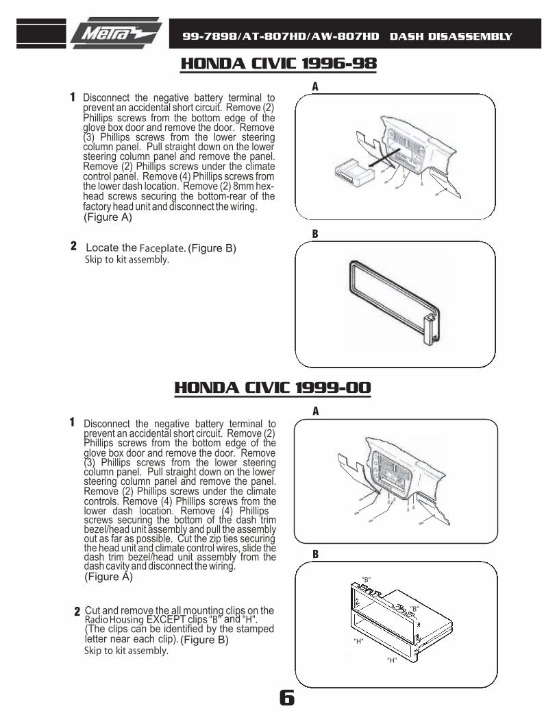
Disconnect the negative battery terminal to prevent an accidental short circuit. Remove (2) Phillips screws from the bottom edge of the glove box door and remove the door. Remove (3) Phillips screws from the lower steering column panel. Pull straight down on the lower steering column panel and remove the panel.Remove (2) Phillips screws under the climate control panel. Remove (4) Phillips screws from the lower dash location. Remove (2) 8mm hex-head screws securing the bottom-rear of the factory head unit and disconnect the wiring.
Locate the Faceplate.
Disconnect the negative battery terminal to prevent an accidental short circuit. Remove (2) Phillips screws from the bottom edge of the glove box door and remove the door. Remove (3) Phillips screws from the lower steering column panel. Pull straight down on the lower steering column panel and remove the panel.Remove (2) Phillips screws under the climate controls. Remove (4) Phillips screws from the lower dash location. Remove (4) Phillips screws securing the bottom of the dash trim bezel/head unit assembly and pull the assembly out as far as possible. Cut the zip ties securing the head unit and climate control wires, slide the dash trim bezel/head unit assembly from the dash cavity and disconnect the wiring.
Cut and remove the all mounting clips on the Radio Housing EXCEPT clips "B" and "H".(The clips can be identified by the stamped letter near each clip).Skip to kit assembly.
Skip to kit assembly.
99-7898/AT-807HD/AW-807HD
7
1
HONDA CIVIC SE 2005 (only)
DASH DISASSEMBLY
A
B
C
(Figure C)
(Figure B)
2
3
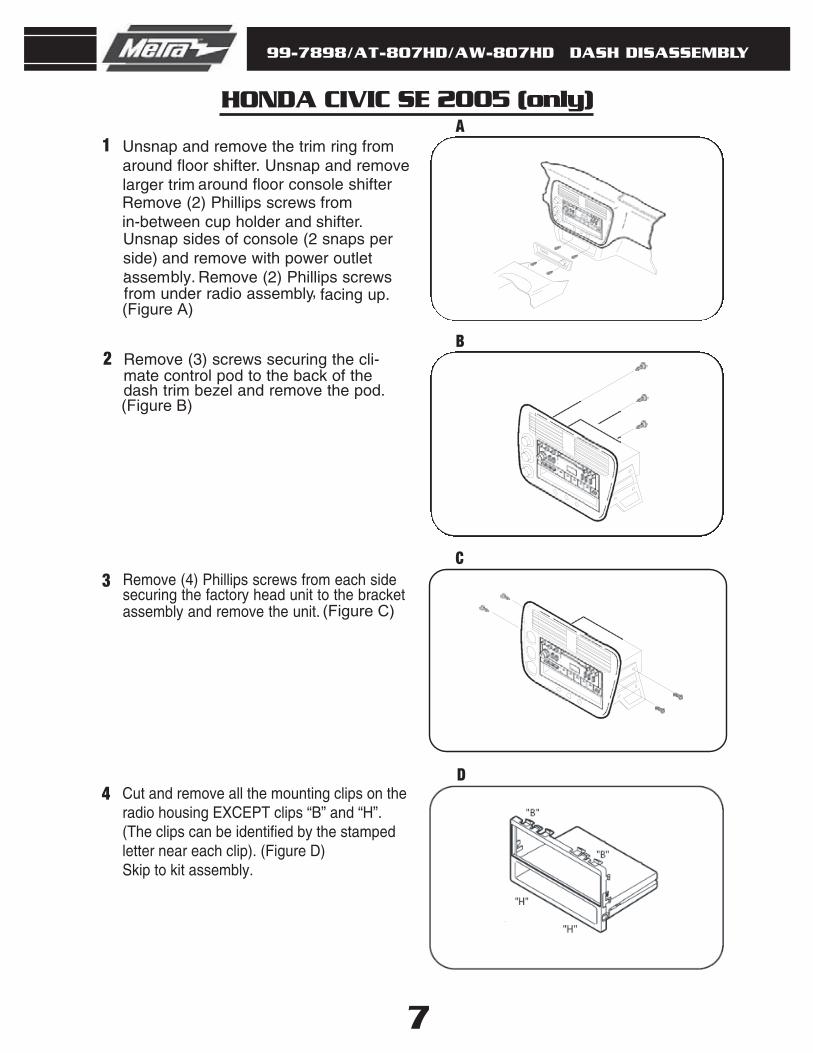
Remove (3) screws securing the cli-mate control pod to the back of thedash trim bezel and remove the pod.
Remove (4) Phillips screws from each sidesecuring the factory head unit to the bracketassembly and remove the unit.
(Figure A)
Unsnap and remove the trim ring from around floor shifter. Unsnap and remove larger trim around floor console shifter
.
Remove (2) Phillips screws from in-between cup holder and shifter. Unsnap sides of console (2 snaps per side) and remove with power outlet assembly.. Remove (2) Phillips screws
, facing up.from under radio assembly
4 Cut and remove all the mounting clips on theradio housing EXCEPT clips “B” and “H”. (The clips can be identified by the stamped letter near each clip). (Figure D) Skip to kit assembly.
D
99-7898/AT-807HD/AW-807HD
8
1
HONDA CRV 1997-01
DASH DISASSEMBLY
A
B
B
A
HONDA CRV 2002-06
(Figure A)
(Figure B)
2
1
2
(Figure A)
(Figure B)
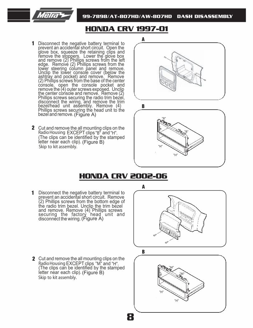
Disconnect the negative battery terminal to prevent an accidental short circuit. Open the glove box, squeeze the retaining clips and remove the stoppers. Lower the glove box and remove (2) Phillips screws from the left edge. Remove (2) Phillips screws from the lower steering column panel and remove.Unclip the lower console cover (below the ashtray and pocket) and remove. Remove (2) Phillips screws from the base of the center console, open the console pocket and remove the (4) outer screws exposed. Unclip the center console and remove. Remove (2) Phillips screws securing the radio trim bezel, disconnect the wiring, and remove the trim bezel/head unit assembly. Remove (4) Phillips screws securing the head unit to the bezel and remove.
Cut and remove the all mounting clips on the Radio Housing EXCEPT clips "B" and "H".(The clips can be identified by the stamped letter near each clip).Skip to kit assembly.
Disconnect the negative battery terminal to prevent an accidental short circuit. Remove (2) Phillips screws from the bottom edge of the radio trim bezel. Unclip the trim bezel and remove. Remove (4) Phillips screws securing the factory head unit and disconnect the wiring.
Cut and remove the all mounting clips on the Radio Housing EXCEPT clips "M" and "H".(The clips can be identified by the stamped letter near each clip).Skip to kit assembly.
"H"
"H"
"B"
"B"
"H"
"H"
"M"
"M"
99-7898/AT-807HD/AW-807HD
9
1
HONDA ODYSSEY 1995-98/ISUZU OASIS 1996-99
DASH DISASSEMBLY
A
B
B
A
HONDA ODYSSEY 1999-04
(Figure A)
(Figure B)
2
1
2
(Figure A)
(Figure B)
"D"
"D"
"H"
"H"
"B"
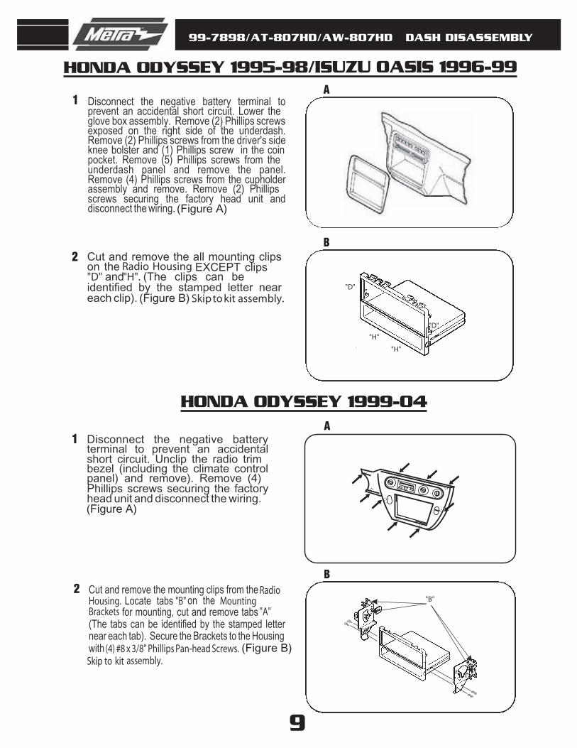
Disconnect the negative battery terminal to prevent an accidental short circuit. Lower the glove box assembly. Remove (2) Phillips screws exposed on the right side of the underdash.Remove (2) Phillips screws from the driver's side knee bolster and (1) Phillips screw in the coin pocket. Remove (5) Phillips screws from the underdash panel and remove the panel.Remove (4) Phillips screws from the cupholder assembly and remove. Remove (2) Phillips screws securing the factory head unit and disconnect the wiring.
Cut and remove the all mounting clips on the Radio Housing EXCEPT clips "D" and"H". (The clips can be identified by the stamped letter near each clip). Skip to kit assembly.
Disconnect the negative battery terminal to prevent an accidental short circuit. Unclip the radio trim bezel (including the climate control panel) and remove). Remove (4) Phillips screws securing the factory head unit and disconnect the wiring.
Cut and remove the mounting clips from the RadioHousing. Locate tabs "B" on the MountingBrackets for mounting, cut and remove tabs "A".(The tabs can be identified by the stamped letter near each tab). Secure the Brackets to the Housing with (4) #8 x 3/8" Phillips Pan-head Screws. Skip to kit assembly.
99-7898/AT-807HD/AW-807HD
10
1
HONDA PRELUDE 1989-91
DASH DISASSEMBLY
A
B
B
A
HONDA PRELUDE 1992-96
(Figure A)
(Figure B)
2
1
2
(Figure A)
(Figure B)"A"
"A"
"C"
"C"
"H"
"H""F"
"F"
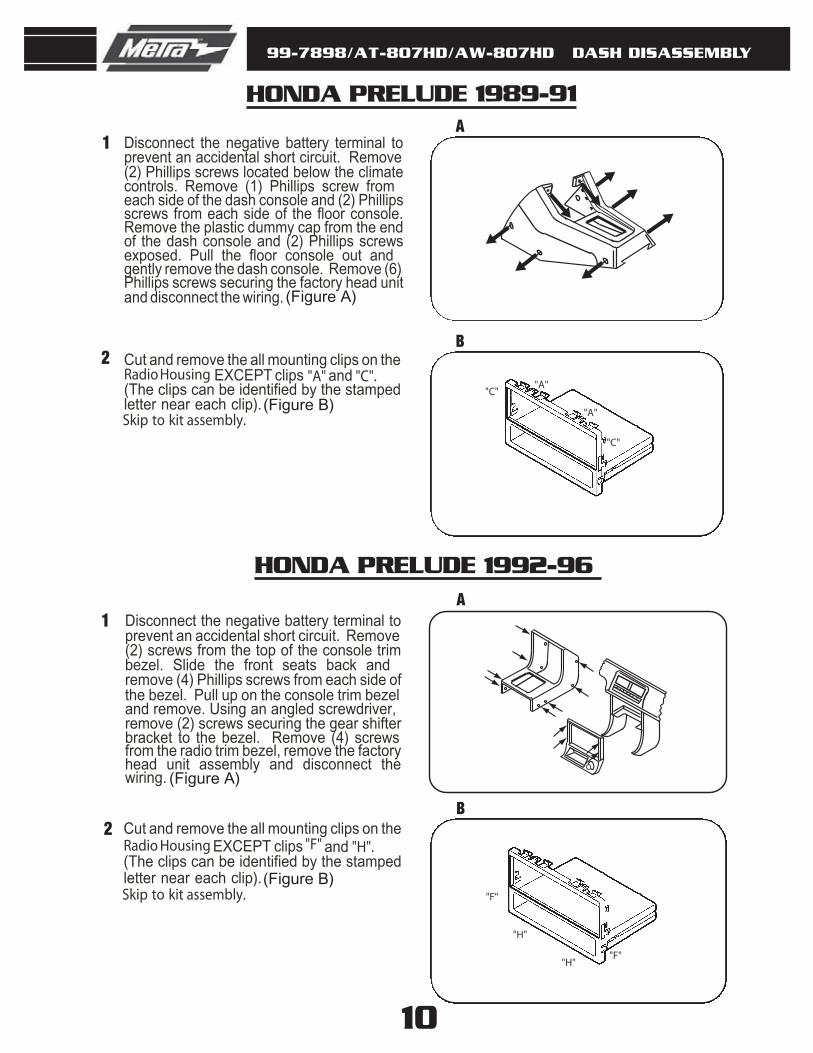
Disconnect the negative battery terminal to prevent an accidental short circuit. Remove (2) Phillips screws located below the climate controls. Remove (1) Phillips screw from each side of the dash console and (2) Phillips screws from each side of the floor console.Remove the plastic dummy cap from the end of the dash console and (2) Phillips screws exposed. Pull the floor console out and gently remove the dash console. Remove (6) Phillips screws securing the factory head unit and disconnect the wiring.
Cut and remove the all mounting clips on the Radio Housing EXCEPT clips "A" and "C".(The clips can be identified by the stamped letter near each clip).Skip to kit assembly.
Disconnect the negative battery terminal to prevent an accidental short circuit. Remove (2) screws from the top of the console trim bezel. Slide the front seats back and remove (4) Phillips screws from each side of the bezel. Pull up on the console trim bezel and remove. Using an angled screwdriver, remove (2) screws securing the gear shifter bracket to the bezel. Remove (4) screws from the radio trim bezel, remove the factory head unit assembly and disconnect the wiring.
Cut and remove the all mounting clips on the Radio Housing EXCEPT clips "F" and "H".(The clips can be identified by the stamped letter near each clip).Skip to kit assembly.

99-7898/AT-807HD/AW-807HD
1
HONDA PRELUDE 1997-01
DASH DISASSEMBLY
A
B2
(Figure A)
(Figure B)
11
"G"
"A"
"A"
"G"
Disconnect the negative battery terminal to prevent an accidental short circuit. Using a panel removal tool, unclip the radio trim bezel and remove (some force may be required).Remove (4) Phillips screws securing the factory head unit/bracket housing assembly and disconnect the wiring. Remove (4) Phillips screws securing the factory head unit to the bracket housing and remove.
Cut and remove the all mounting clips on the Radio Housing EXCEPT clips "A" and "G".(The clips can be identified by the stamped letter near each clip).Skip to kit assembly.
CIVIC 1996-98
DIN HEAD UNITS:
99-7898/AT-807HD/AW-807HD KIT ASSEMBLY
(Disconnect the negative battery terminal to prevent an accidental short circuit. Position the Faceplatein the radio opening by inserting the locating pins on the Housing into the holes in the sub-dash. (NOTE: If a radio dummy plate was removed during the dash disas-sembly, cut and remove the locating pins on the Radio Housing). Slide the DIN cage into the kit and secure by bending the metal locking tabs down. Slide the aftermarket head unit into the cage until secure.(THIS CONCLUDES THE INSTALLA-TION). (Figure A)
Fig. A
99-7898/AT-807HD/AW-807HD KIT ASSEMBLY
Fig. C
Fig. D
Fig. A
Fig. B
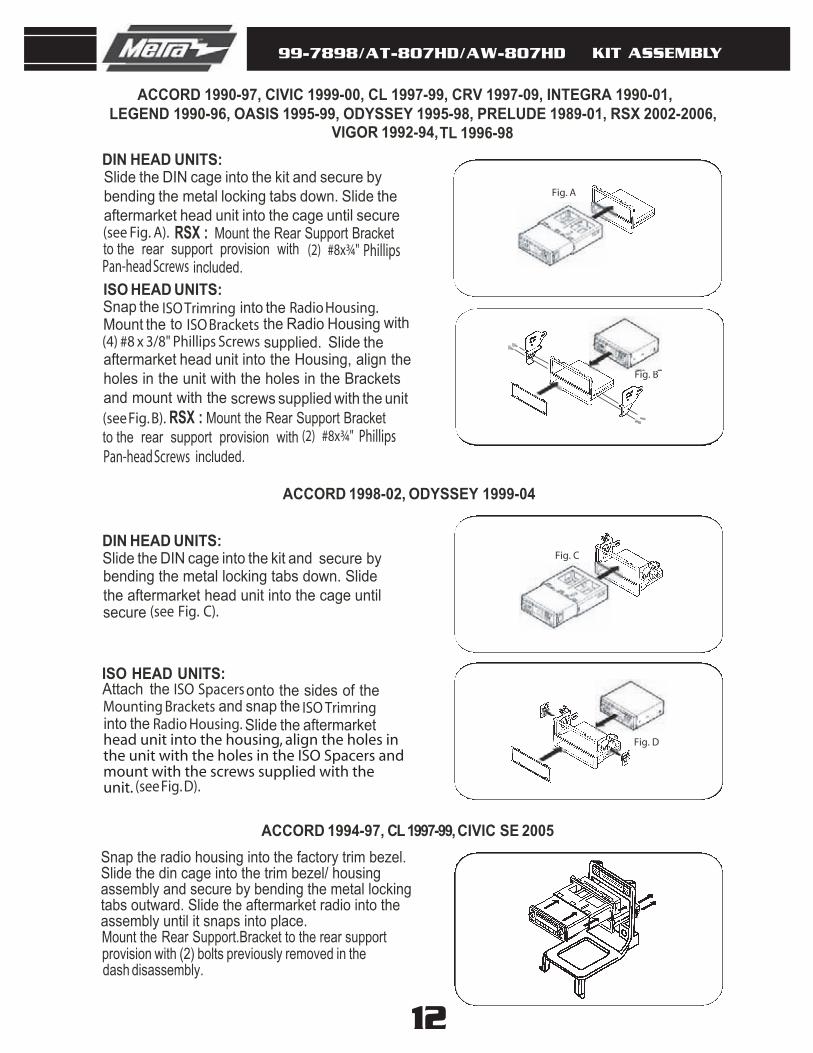
ACCORD 1994-97, CL 1997-99, CIVIC SE 2005
(see Fig. D).
Mount the Rear Support.Bracket to the rear support provision with (2) bolts previously removed in the dash disassembly.
Snap the radio housing into the factory trim bezel.Slide the din cage into the trim bezel/ housing assembly and secure by bending the metal locking tabs outward. Slide the aftermarket radio into the assembly until it snaps into place.
onto the sides of the Mounting Brackets and snap the ISO Trimring into the Radio Housing. Slide the aftermarket
Attach the ISO SpacersISO HEAD UNITS:
DIN HEAD UNITS:Slide the DIN cage into the kit and
until (see Fig. C).
secure by bending the metal locking tabs down. Slide the aftermarket head unit into the cage secure
12
Phillips
VIGOR 1992-94,
ACCORD 1990-97, CIVIC 1999-00, CL 1997-99, CRV 1997-09, INTEGRA 1990-01, LEGEND 1990-96, OASIS 1995-99, ODYSSEY 1995-98, PRELUDE 1989-01, RSX 2002-2006,
TL 1996-98
RSX : Mount the Rear Support Bracket to the rear support provision with (2) #8x¾"
included.
DIN HEAD UNITS:
(see Fig. A).
Slide the DIN cage into the kit and secure by bending the metal locking tabs down. Slide the aftermarket head unit into the cage until secure
Pan-head ScrewsISO HEAD UNITS:
Snap the ISO Trimring into the Radio Housing. Mount the ISO Brackets to the Radio Housing with(4) #8 x 3/8" Phillips Screws supplied. Slide the
screws supplied with the unit (see Fig. B). RSX : Mount the Rear Support Bracket to the rear support provision with
aftermarket head unit into the Housing, align theholes in the unit with the holes in the Brackets and mount with the
(2) #8x¾" Phillips included.Pan-head Screws
head unit into the housing, align the holes in the unit with the holes in the ISO Spacers and mount with the screws supplied with the unit.
ACCORD 1998-02, ODYSSEY 1999-04
99-7898/AT-807HD/AW-807HD FINAL ASSEMBLY
13
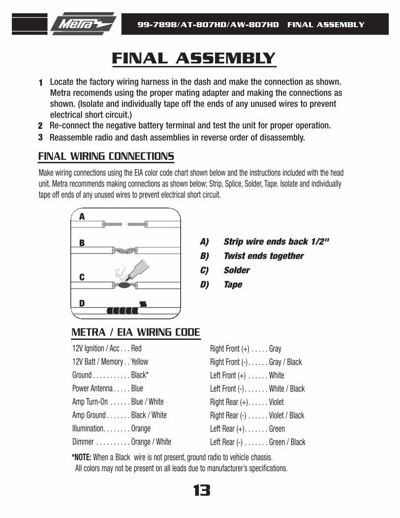
FINAL ASSEMBLY1 Locate the factory wiring harness in the dash and make the connection as shown.
Metra recomends using the proper mating adapter and making the connections asshown. (Isolate and individually tape off the ends of any unused wires to preventelectrical short circuit.)
2 Re-connect the negative battery terminal and test the unit for proper operation.3 Reassemble radio and dash assemblies in reverse order of disassembly.
A
A) Strip wire ends back 1/2"
B) Twist ends together
C) Solder
D) Tape
B
C
D
Make wiring connections using the EIA color code chart shown below and the instructions included with the headunit. Metra recommends making connections as shown below; Strip, Splice, Solder, Tape. Isolate and individuallytape off ends of any unused wires to prevent electrical short circuit.
12V Ignition / Acc . . . Red
12V Batt / Memory . . Yellow
Ground . . . . . . . . . . . Black*
Power Antenna . . . . . Blue
Amp Turn-On . . . . . . Blue / White
Amp Ground . . . . . . . Black / White
Illumination. . . . . . . . Orange
Dimmer . . . . . . . . . . Orange / White
Right Front (+) . . . . . Gray
Right Front (-) . . . . . . Gray / Black
Left Front (+) . . . . . . White
Left Front (-) . . . . . . . White / Black
Right Rear (+). . . . . . Violet
Right Rear (-) . . . . . . Violet / Black
Left Rear (+). . . . . . . Green
Left Rear (-) . . . . . . . Green / Black
*NOTE: When a Black wire is not present, ground radio to vehic le chassis.All colors may not be present on all leads due to manufacturer’s specifications.
METRA / EIA WIRING CODE
FINAL WIRING CONNECTIONS
99-7898/AT-807HD/AW-907HD INSTRUCTIONS
1-800-221-0932 www.metraonline.com© COPYRIGHT 2004-2008 METRA ELECTRONICS CORPORATION INST99-7898REV. 09/09/08
INSTALLER INSTITUTETurn your hobby into a career at Installer Institute, the educational leader of the mobile electronics industry.Log onto www.installerinstitute.com or call 800-354-6782 for more information and start your new career today.
TOP VIEW OF RADIO HOUSING MOUNTING CLIPS
B BM MA A
BOTTOM VIEW OF RADIO HOUSING MOUNTING CLIPS
G GJ JH H
K K
F
D
E
C
F
D
E
C
RIGHT SIDE LEFT SIDE
SIDE VIEW OF RADIO HOUSING


![AW-UE4WGN [ホワイトモデル] AW-UE4KGN · aw-ue4 111° 出力フォーマット(暫定) lan ケーブル usb ケーブル aw-ue4wgn/kgn aw-ue4wgn/kgn 映像信号 制御信号](https://img.pdfslide.net/doc/110x75/5e1e781d43bdcd47187de59b/aw-ue4wgn-ffffff-aw-ue4kgn-aw-ue4-111-ffffffii.jpg)