Embed Size (px)
Citation preview

Ept2 Wiring Instructions By Al Lococo
99 Ford Ranger EV EPT2
ConversionWiring Instructions
There are two electrical systems. One 144 volt high current traction circuit and one low voltage control and accessory circuit.
The low voltage circuit is a nominal 12 volt system. It uses a 12 volt accessory battery maintained by a 30 amp Iota DC – DC converter using the 144 volt traction pack as the input source. The 12 volt system (battery and converter) power several components.
We have essential circuits for traction control, essential accessories like vacuum brake system and Power steering system, and optional accessories like Air Conditioner Clutch. Many existing circuits like lighting, radio and blower are unmodified.
The objective is to modify as little as possible and retain and use as much of the existing wiring as possible for new or replacement components. The goal is that all remaining existing functions such as air bags and 4 wheel ABS brakes should continue to function normally. In addition servicing procedures for all remaining existing functions should be unchanged. Wiring diagrams for remaining existing circuits should continue to be useful.
New circuits and modified circuits should be documented with modified diagrams.
The heavy Yellow /Light Blue wire to the starter relay is saved for the new Key Start Function. The Red wire powering the distributor/ignition module is saved for the Key On function. The heavy Black/Orange (Pink?) wire from the alternator is saved for the DC – DC converter output. The Air Conditioner clutch wires (Gray/White and Black) are saved for the new A/C clutch circuit. The water temperature sender and wire is saved to monitor motor temperature. The Inertia Switch Pink/Black wire is saved from the fuel tank harness. The fuel gauge Yellow/White wire and the Black/Orange wires are saved from the fuel tank harness for
the new traction pack capacity indicator. The generator fault light wire Light Green/Red is saved from the alternator harness for the new Run
Indicator. The oil pressure sender wire is saved so that the oil pressure gauge can be used as a vacuum gauge. The brake Position Switch Light Green wire is tapped for use in the throttle control circuit.
New CircuitsKey On Interlock Run indicatorThrottleBrake InterlockMotor Over Temperature Safety SwitchPower Steering Circuit.
Modified circuitsBrake Pedal Position SwitchVacuum GaugeTemperature GaugeFuel GaugeInertia SwitchA/C ClutchDC-DC Converter
Revised 7/1/2011 Page 1 oof 22
Ept2 Wiring Instructions By Al Lococo
Theory of OperationNew Circuits Key On Interlock The Key On circuit activates all components and accessories except the throttle circuit.This circuit is new, but includes a modified Inertia Switch circuit. There are two interlocks which will interrupt the key on circuit, the modified Inertia Switch interlock and the Motor Over Temperature Safety Switch. Both of these switches are normally closed and wired in series. If the motor overheats, the Motor Over Temperature Safety Switch opens and all Key On circuits turn off. The same is true in case of an impact, the Inertia Switch opens and all Key On Circuits turn off.
Key On also activates previously existing functions such as the Computer, speedometer, Air Bags and four wheel ABS.
Run IndicatorThe Run Indicator is described below with other instruments. It is shown in the DC-DC Converter wiring diagram at the lower right. It also appears in the instrument panel diagram at the lower left. This indicator uses the Light Green/Red wire from the alternator harness.
ThrottleThe function of the Throttle circuit is to actuate the Main Throttle Contactor and the KSI Relay. This is a complex circuit with several safety features built in. The coils for the Main Throttle Contactor and the KSI Relay are part of the 12 Volt circuit, although the Normally Open Contacts carry 144 volts to the Controller.The KSI Relay is a SPST relay and is so called because it carries 144 volt to the KSI (Key Switch Input) contact on the controller. This turns the controller on.
This circuit starts at the micro switch in the Pot Box. This switch has three contacts, Common (C), Normally Open (NO) and Normally Closed (NC). To simplify otherwise ambiguous terms, NC is referred to here as TD (Throttle Down) and NO is TU (Throttle Up) and Common (C) referred to as (TC).
This switch has two inputs, TU and TC.
TU is the initial input.If throttle is not pressed, TU is the initial input supplied by Key Start leaving the micro switch at TC and headed for the Brake relay, a SPDT, relay, Common. Subsequently TC becomes the input, but we will get to that later.
If the Brake is depressed, the Key Start positive 12 volt signal leaves the Brake Relay at NO (Brake Down). This picks and holds the Interlock Relay, a SPST relay, allowing the Key On signal to enter the Interlock Relay at Common and leave at NO available at the Brake Relay NC (Brake Up).
From this point on the Interlock relay is picked (NO contacts closed) until Key Off or an Inertia Switch interrupt or a Motor Over Temperature Safety Switch Interrupt. While the Brake is not depressed, the Key On signal is not available at TC. As soon as you take your foot off the Brake the Throttle is enabled. From this point on every time you press the Brake the Throttle is disabled.
Now TC becomes the input. When you press the Throttle, the Throttle Micro Switch closes and the Key On 12 volt signal comes from the Brake relay NC (BU) into the Micro Switch TC and out through the TD contact to the KSI relay Coil and the Main Throttle Contactor coil. If you are in any gear other than neutral the car is moving.
Revised 7/1/2011 Page 2 oof 22

Ept2 Wiring Instructions By Al Lococo
Each time the Throttle is pressed the Controller starts and each time the Throttle is released the controller turns off. Regardless of the Throttle position, pressing the Brake will always interrupt the Key On signal to the Micro Switch, and ultimately the KSI and Main Throttle Contactor, and turn off the Controller if it is on.
Brake Interlock
This circuit has two functions. It provides the path to the Interlock Relay for the Key Start signal, once, at start up. And, it provides the path for the Key On signal to the Throttle Micro Switch. Any time the Brake is pressed, the Brake Relay interrupts the Key On signal to the Throttle Micro Switch.
In addition to the coil suppression diode on all relay, contactor and solenoid coils in this vehicle, the Brake circuit has two additional diodes. Without these diodes the Key Start signal would find its way to the Interlock Relay coil, through either the NO or NC path in the Brake Relay, whether the Brake was pressed or not. At the same time, without these diodes the Key On signal would find its way to the throttle Micro Switch through either the NO or NC path in the Brake Relay.
The diode on the Brake NO (BD) contact allows flow to the Interlock Relay only. The diode on the NC (BU) contact allows flow to the Throttle Micro Switch only.
Motor Over Temperature Safety SwitchThe Netgain Motor has two Black wires at the CE (Commutator End), this is the end oppsite the DE (Drive End). These wires are connected to a normally closed (NC) Over Temperature Switch. If the motor gets too hot the switch opens.
This switch is wire in series with the Key On circuit.
Power Steering Circuit.The power steering System has two electrical components, the pump motor and the solenoid control valve. The solenoid control valve is normally open (NO) so that when the pump and the solenoid are without power, steering fluid can flow freely between the steering delivery and return ports. When power is applied to both the pump and the solenoid the solenoid valve closes and free flow is stopped allowing the Power Steering Pump to assist the steering gear. The output of the pump is connected to the steering gear return port and the Steering Gear delivery is connected to the Pump Return.
Modified circuits Brake Pedal Position SwitchA positive 12 Volt signal is required to control the Throttle circuit in an emergency. To start the car the Brake pedal must be depressed and any time after that the Throttle should be disengaged when the brake is depressed.
The fuse 13 in the drivers side dash panel fuse panel supplies the Brake Pedal Position Switch. The output of this switch is tapped to power the coil of the new Brake Relay.
Instruments- Vacuum GaugeThe Oil Pressure Gauge will be the new Vacuum Gauge. The Oil Pressure Sender really only is an on off switch. The wire from the Oil Pressure Sender will be connected to a vacuum operated relay.
- Temperature GaugeThe Water Temperature Sender with existing wiring will be fastened to the motor to indicate abnormal temperatures at the motor on the existing temperature gauge. It may be necessary to put a resistor in parallel with the sender to get a reading on the existing gauge.
Revised 7/1/2011 Page 3 oof 22

Ept2 Wiring Instructions By Al Lococo
- Fuel GaugeThe Fuel Gauge wire from the fuel tank harness will be used to connect a new circuit to the existing fuel gauge. A voltage divider will be used to bring the traction pack voltage down from 157 through 144 to drive an opto isolator which will drive a transistor in series with the fuel gauge wire.
This will provide some degree of knowledge about the capacity of the traction pack to an unsophisticated driver.
Inertia SwitchBoth sides of the existing Inertia Switch will be wired in series with the Key On circuit so that the throttle circuit and all other components will disengage in the event of an accident.
A/C ClutchThe High Pressure Switch and the Low Pressure Switch will be wired inseries with a Dash Board SPST Switch to ground,
DC – DC ConverterThe Converter is an AC – DC device. It comes with a three-pin 110V grounded plug on the input. An outlet is provided on the table top for the converter to plug into. The 144V traction battery powers this outlet. The converter can be unplugged from this DC outlet and plugged into any standard 110V AC outlet.
You can see the outlet here on the lower left. The un-switched positive is supplied through an inline fuse from the bottom contact on the Main-Throttle Contactor. This is always hot. The negative side is wired using a black wire directly to the top contact of the Key On-Bypass contactor. This is only hot when Key On. It is important to note that both the positive Main Throttle contactor and negative Key On-Bypass contactor are fed at the bottom
The black wire in the outlet goes to the Chrome screw and the red wire goes to the bronze screw on the outlet.
This image also shows the Run Indicator Relay mounted on top of the Key On-Bypass contactor.
Revised 7/1/2011 Page 4 oof 22

Ept2 Wiring Instructions By Al Lococo
The converter negative output is wired directly to ground. The positive output is wired through an inline fuse to the Black/Orange, looks like pin to me, wire from the alternator harness. See diagram.
The Converter, the Vacuum Pump, the Throttle Pot, relays and contactors are mounted on the table top. These low voltage components are connected to off board circuits via two connectors. These are salvaged oxygen sensor connectors, one Green and one purple.
In the lower right corner of this picture, you can see the green and purple connectors. This shows what they look like and where they are located in the finished vehicle.
IOTA Charge JackThe wire from dash switch to DC-DC Converter provides the function of the chaarge ak under switch control.jIn the left position The converter is putting out 14.2 volts. In the right position it puts out 13.6 volts.Black-Green
Revised 7/1/2011 Page 5 oof 22

Ept2 Wiring Instructions By Al Lococo
Green 4 pin connector
The green 4 pin connector used to connect the ammeter and voltmeter to the table top. the table top side of the green connector for the traction battery gauges in the pod is Wired so that Blue and Green are attached to the battery side of the shunt. Yellow is connected to the contactor side of the shunt and the brown wire is connected to the positive post on the outlet that powers the converter.
On the off table side the green connector is wired as follows. Wire Extension cable is six wire cable, with 12V illumination Red/White, 144V voltmeter Brown/Blue, Ammeter Yellow/Green, +/- pairs. The Red and White wire exit the cable at the fuse panel in the passenger compartment by the drivers door.
Remove Light blue/ Red wire from instrument panel dimmer knob. Use tiny screwdriver to pull wire and contact from plastic plug. Solder short jumper lead to back of contact and reinstall in plug. Put plugs back on head light switch and dimmer knob. Cut shield on cable and pull out Red wire. Put spade type connecter on Red wire and short jumper lead from dimmer switch. Connect Red wire to the jumper. The White wire is attached to a convenient ground.
Revised 7/1/2011 Page 6 oof 22

Ept2 Wiring Instructions By Al Lococo
Purple 4 pin connector
The purple connector carries Key On, Key Start, Brake Down and Run Indicator in the Table Top. Key On and Brake Switch go to the interlock relay panel through the inertia switch and the Motor Temperature safety interlock switch. Key Start goes to the throttle Pot and the Run indicator goes to the Run Indicator Relay mounted on top of the Bypass / Key On contactor.
Key On is taken from the Red distributor ignition wire. Trace this wire back into harness. At its source it splits to power several removed components. Trim this down to one wire.
Key Start is taken from the starter relay wire. This is interlocked with the clutch pedal position switch. Since the clutch has been removed, this interlock needs to be disabled. This was done mechanically by using a bolt to compress the CPPS spring permanently.
A better solution might be to remove the switch and rewire. The clutch cylinder switch, is really three separate single pole single throw switches. When depressed pins 1 to 2 and 5 to 6 are connected. When released pin 3 to 4 is connected.
Or, another choice would be to replace the switch with a relay operated by the new Brake Pedal Position line.
ConnectionsKO – Bypass Key On Coil
-Interlock commonVacuum Pump
KS -Throttle UpTD -Main Throttle Coil
-KSI CoilBD - Diode Anode to Interlock CoilBU -Diode Cathode to Interlock CoilBC -TCIO -Interlock Coil
-Run Indicator CoilIC -KOKSO -KSIKSC - Main Throttle NO
DefinitionsIO =Interlock OnIC = Interlock CommonKO = Key On GreenKS = Key StartTD = Throttle Down WhiteTU = Throttle UpBD = Brake DownBU = Brake UpBS = Brake Switch RedTC = Throttle Common BlackBC = Brake CommonMTI = Motor Temperature InterlockIS = Inertia Switch InterlockKSI = KSI contact on Controller (Top Post)KSO = KSI Relay NOKSC =KSI Relay Common
Revised 7/1/2011 Page 7 oof 22
Ept2 Wiring Instructions By Al Lococo
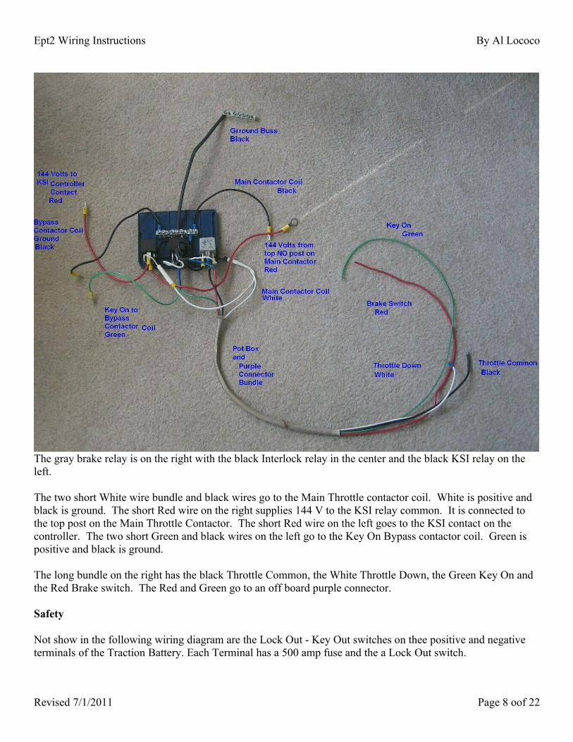
The gray brake relay is on the right with the black Interlock relay in the center and the black KSI relay on the left.
The two short White wire bundle and black wires go to the Main Throttle contactor coil. White is positive and black is ground. The short Red wire on the right supplies 144 V to the KSI relay common. It is connected to the top post on the Main Throttle Contactor. The short Red wire on the left goes to the KSI contact on the controller. The two short Green and black wires on the left go to the Key On Bypass contactor coil. Green is positive and black is ground.
The long bundle on the right has the black Throttle Common, the White Throttle Down, the Green Key On and the Red Brake switch. The Red and Green go to an off board purple connector.
Safety
Not show in the following wiring diagram are the Lock Out - Key Out switches on thee positive and negative terminals of the Traction Battery. Each Terminal has a 500 amp fuse and the a Lock Out switch.
Revised 7/1/2011 Page 8 oof 22

Ept2 Wiring Instructions By Al Lococo
Below you can see the red flag keyed Lock Out Switch. When Key is removed, the positive terminal is open. No connection to the circuit breaker on the table top.
You can also see the green knob, which switches off the accessory battery.
On the right above, you can see the red flag keyed Lock Out Switch. When Key is removed, the negative terminal is open. No connection through the conduit to shunt on the table top. When working on the car, turn the red flag keys and remove them and turn the Green Knob counter Clockwise. At this pint it is safe to work on the car. Keep the red flag keys in your pocket, that way nobody can turn the power on while you are working.
Also not included in the wiring diagram are some interlock and the instrumentation circuits.
Revised 7/1/2011 Page 9 oof 22

Ept2 Wiring Instructions By Al Lococo
Revised 7/1/2011 Page 10 oof 22

Ept2 Wiring Instructions By Al Lococo
Run IndicatorUse a relay to turn on the charge indicator (an icon of a battery) as a Run Indicator. Use the Light Green/Red wire from the alternator harness. . Can’t wire it backwards because the Air Bags are on the same fuse. Mount the relay on top of the Bypass/Key On contactor. It gets picked when the interlock relay closes. Tap the NO terminal of the Throttle Interlock relay. The new Run indicator, previously charge indicator, is grounded through the NO contact on the new Run Indicator relay. This indicates that the automobile is on (ready to drive, throttle enabled).
Vacuum GaugeThe Vacuum pressure switch has three contacts, C, NO, and NC. Use the NC to drive the oil pressure gauge. The oil pressure sensor worked the same way. The needle had only two positions, up (normal) and down (low) pressure. The Gauge will now indicate normal vacuum (up) and loss of vacuum (down).
The switch is adjustable. I found it to be reasonable without any changes.
There is some weight to the idea of having the needle down for normal vacuum and up for loss of vacuum. I like it the other way. The vacuum switch is capable of being wired either way, if desired.
Temperature Gauge The sender has two terminals but only one wire on the socket. Find a two wire socket that almost fits on the sender. File off the alignment dog so it fits. Install and solder wires for temperature gauge. Ground the second wire.
Fuel GaugeI know how to move the needle but I don’t know how to make practical use of it yet. I have a 47 ohm resistor between the Yellow/White wire and the Black/Orange wire in the fuel tank harness. It is indicating one quarter full. Full is145 ohms and empty is 22 ohms. Without a resister it indicates way over full.
Brake SwitchThe picture below shows the brake position switch center left and the five wires center right . It looks like a Brown wire on the left and the Light Green with the Red stripe next to it. Next wire moving to the right is a Red wire with a Violet stripe. Next an un-striped Light Green and last Gray wire. Research on the Auto Zone web site shows a simplified wiring diagram indicates the brake switch supplied by a Light Green wire with a Red stripe and an un-striped Light Green wire coming out of it.
Revised 7/1/2011 Page 11 oof 22

Ept2 Wiring Instructions By Al Lococo
Further evidence is the fact that the two Light Green wires are of a heavier gauge than the others. Tap the un-striped Light Green wire. Pull the wire bundle open and separate it from the switch to get access to the wire for the tap.
Use a diode to make sure no 12V signals from the table Top find their way into the brake control system. Run the new brake wire out the door and do a few tests show that the wire was providing 12 Volts to the coil of the brake relay on the Table Top.
The diode should be connected so that the band (the Cathode) points to the brake Relay. This allows flow from the brake pedal position switch to the brake relay coil and then to ground. Reverse flow is prevented.
After testing, the wire is routed through the firewall with the wires from the instrument pod through the hole previously used by the Clutch Push Rod. A harness can then be wrapped with these wires and the Key On and Key Start wires. The third wire is now added to the Purple connector to the table top, giving us Key On, Key Start and Brake Down in the connector.
Remaining InterlocksWire the Over Temperature safety interlock switch in motor. These two wires are wired in series with the Key On wire before it goes to the Table Top. The Inertia Switch is part of this series sequence. A severe impact or motor over heating will interrupt Key On. In This case the car can not be restarted until the condition is cleared, the brake depressed while the key turned to the key start position.
A bundle was created including the Motor Over Temperature Safety Switch and the motor temperature sensor. These wires were included in a harness that terminates near the fuse box. The wires for the A/C sensor in the high pressure line were included in a separate harness.
Revised 7/1/2011 Page 12 oof 22

Ept2 Wiring Instructions By Al Lococo
Inertia SwitchThe factory Inertia Switch is located on the firewall under the glove box. The wires are integrated in the fuel tank harness.
Research on the Gas gauge, leads to the fact that the inertia switch Pink/Black wire is in the Fuel Tank harness. Further research shows that the Green/Yellow input to the inertia switch is from the fuel pump relay, which is located in the fuse box under the hood. Relay number 5 (between 4 and 7 Shown removed) on the far right is the one. Remove and discard the relay. The NO contact (pin 5) is the lower, or large center slot, of the two horizontal contacts just above the row of three smaller vertical contacts. A wire with a spade connector is inserted here. The Pink/Black wire in the Fuel Tank harness is the other.
The Fuel Tank harness is separated from the harness running along the frame to the rear bumper up to a point under the cab. From there it is folded forward and routed to the engine compartment. The inertia Switch is then wired in series with the motor over temperature switch in the Key On wire. The gas
gauge wire harness is conveniently located for future enhancements.
Put a spade connector on the Key On wire and plug it into Pin 5 of the Fuel Pump Relay socket (Relay #5).
This sends the Key On signal over the Green/Yellow wire to the Inertia Switch. It goes through the Inertia Switch to the Pink/Black wire. Put a plug on the Motor Over Temperature wires. Connect the Pink/Black wire to one of the wires from the Motor Over Temperature Plug. This forwards Key On through the Over Temperature Switch and Plug to the other wire. Connect this to the Purple Connector going to the table top.
Here you can see the routing of the Key On wire to Pin 5 of the fuel Pump Relay Which goes to the Inertia Switch wire between relays 4 and 7. You can also see the modification to relay #2 described below.
Revised 7/1/2011 Page 13 oof 22

Ept2 Wiring Instructions By Al Lococo
The inertia Switch wire is Pink/Black. A gentle tap, with a small hammer,on the inertia switch shows that the power to the table top is lost when the inertia switch trips. Pressing the reset button on top of the switch allows the ignition switch to be used to restart.
Air Conditioner Control
Test the A/C with a jumper wire on pins 3 and 5 in the fuse box where the A//C relay #2 is. It should cool even at the low RM provided by the motor at 12 Volts, with the compressor load on it. Rewire the compressor.
1- Coil2- Coil3- C (Common)4- NC (Normally Closed)5- NO (Normally Open)
Revised 7/1/2011 Page 14 oof 22

Ept2 Wiring Instructions By Al Lococo
The computer will not provide ground to the coil on the compressor relay due to the fact that the ICE is not running (I wonder why). Take the cover off the relay and add a ground wire to pin 1 on the coil, which runs out of the Fuse box to ground. The problem with just this modification is that the compressor clutch comes on with Key On and stays on until Key Off.
There are two sensors monitoring pressure, one on the high side and one on the low. The computer uses these inputs to turn the compressor off when appropriate. The sensors are normally closed switches. They have to be taken away from the computer. The black/Yellow wire goes from the computer to the low side and the Red/Yellow goes from the low side to the high side. The black/White wire goes from the high side to ground.
The strategy is to take the black/Yellow and the black/White and make a ground line for the compressor coil. Trace the black/Yellow wire from the Accumulator to the drivers side of the condenser right next to the High side sensor. Join the black/White wire to the ground wire added to Compressor relay coil.
Take the black/Yellow wire and solder a long White wire to it and rout it into the passenger compartment through the fire wall. You can leave a long loop under the hood near the fuse box. The plan is to put a switch on the dash to provide the final ground for the compressor relay coil . The loop under the hood can be cut to insert a ground interrupt when the throttle is up and the motor is not turning (optional).
Remove the escutcheon around the radio and cut a rectangular hole for a rocker switch. The switch is a SPST. We still have to wire it and put everything back together. Although it isn’t finished yet, test the Compressor Clutch wiring by touching the White ground wire to the chassis. Also disconnected the low side and high side sensors one at a time to be sure the clutch will stays off. The final setup should provide normal A/C operation with two exceptions. First, you will have to turn on the compressor rocker switch on in addition to the normal A/C controls. Second, the A/C will not operate when the car is stopped.
Reinstall radio escutcheon with new Compressor Clutch Switch.
The rocker switch is next to the radio on the left.
Revised 7/1/2011 Page 15 oof 22

Ept2 Wiring Instructions By Al Lococo
General Information
This drawing shows how to use a 100 volt 3 amp suppression diode on a relay coil.
This diagram shows proper orientation of diode with schematic.
This is a picture of a single pole double throw relay pin-outs. The center pin 87a is normally closed. The top pin, 87, is normally open. It closes (is picked) when the coil is actuated. The bottom pin, 30 is common. Aany signal applied here is routed to 87a normally and 87 when the relay is picked. The remaining two pins on each side, 85 and 86, are the coil connections. This is where the suppression diode is connected. It must be connected so that the band at the cathode is on the plus 12 volt side of the coil.
Sockets are available for these relays. They can be wired with spade connectors, but a socket is easier if replacement becomes necessary
The term Multi Function Switch used in wiring diagrams refers to the switch in the directional signal arm used for wipers, lights and such.
Revised 7/1/2011 Page 16 oof 22

Ept2 Wiring Instructions By Al Lococo
Illustration 1: Run Indicator Diagram
Revised 7/1/2011 Page 17 oof 22

Ept2 Wiring Instructions By Al Lococo
Revised 7/1/2011 Page 18 oof 22
Illustration 2: Air Conditioner Clutch Diagram

Ept2 Wiring Instructions By Al Lococo
Revised 7/1/2011 Page 19 oof 22
Illustration 3: DC – DC Converter Diagram

Ept2 Wiring Instructions By Al Lococo
Revised 7/1/2011 Page 20 oof 22
Illustration 4: Inertia Switch Wiring Diagram.

Ept2 Wiring Instructions By Al Lococo
Revised 7/1/2011 Page 21 oof 22

Ept2 Wiring Instructions By Al Lococo
Table of ContentsWiring Instructions..................................................................................................................................................1
New Circuits........................................................................................................................................................1Modified circuits.................................................................................................................................................1
Theory of Operation.................................................................................................................................................2New Circuits........................................................................................................................................................2Modified circuits.................................................................................................................................................3 IOTA Charge Jack..............................................................................................................................................5
Green 4 pin connector..............................................................................................................................................6Purple 4 pin connector.............................................................................................................................................7
Connections.........................................................................................................................................................7Definitions...........................................................................................................................................................7Safety...................................................................................................................................................................8Vacuum Gauge..................................................................................................................................................11Temperature Gauge...........................................................................................................................................11Fuel Gauge........................................................................................................................................................11
Brake Switch..........................................................................................................................................................11Remaining Interlocks.............................................................................................................................................12
Inertia Switch....................................................................................................................................................13Air Conditioner Control.........................................................................................................................................14General Information...............................................................................................................................................16
Revised 7/1/2011 Page 22 oof 22