Embed Size (px)
Citation preview
** WARNING ** WARNING ** WARNING ** WARNING **This document is intended for informational purposes only.
Users are cautioned that Caltrans does not assume any liability or responsibility based on these electronic files or for any defective or incomplete copying, exerpting, scanning, faxing or downloading of the contract documents. As always, for the official paper versions of the bidders and non-bidder packages, write to the California Department of Transportation, Plans and Bid Documents, Room 0200, P.O. Box 942874, Sacramento, CA 94272-0001, telephone (916) 654-4490 or fax (916) 654-7028. Office hours are 7:30 a.m. to 4:15 p.m. When ordering bidder or non-bidder packages it is important that you include a telephone and fax number, P.O. Box and street address so that you can receive addenda.
Note: Addenda information is NOT included with the electronic documents available via electronic file transfer. Only bidder or non-bidder package holders listed with the Caltrans Plans and Bid Documents section as described above will receive addenda information.
etric
Caltrans
STATE OF CALIFORNIA
DEPARTMENT OF TRANSPORTATION__________________________________________________________
NOTICE TO CONTRACTORSAND
SPECIAL PROVISIONSFOR HIGHWAY PLANTING ON STATE HIGHWAY IN
SAN DIEGO COUNTY IN SAN DIEGO FROM 0.4 km EAST OF NIMITZ BOULEVARD
TO ROUTE 8/5 SEPARATION
DISTRICT 11, ROUTE 8
__________________________________________________________
For Use in Connection with Standard Specifications Dated JULY 1999, Standard Plans Dated JULY 1999, and Labor Surcharge and Equipment Rental Rates.
__________________________________________________________
CONTRACT NO. 11-072114
11-SD-8-L1.1/L3.9
Bids Open: January 11, 2001Dated: December 11, 2000

*************************************************************************************************
IMPORTANTSPECIAL NOTICES
*************************************************************************************************This project includes, but is not limited to, the following special requirements:
Attention is directed to Section 3, "Award and Execution of Contract," of these special provisions for special requirements for anticipated time of award and time allowed for return of documents by the successful bidder. If properly executed by the bidder, it is anticipated that the contract will be approved within 24 hours of when the executed contract and contract bonds are received by the Department.
Attention is directed to Section 4, "Beginning of Work, Time of Completion and Liquidated Damages," of these special provisions for special requirements for beginning of work.
SURETY 2000Caltrans is conducting a pilot program in cooperation with Surety 2000, to test electronic bond verification systems. The purpose of the pilot program is to test the use of Surety 2000 for verifying a bidder's bond electronically.
Surety 2000 is an Internet-based surety verification and security system, developed in conjunction with the surety industry. Surety agents may contact Surety 2000 at 1-800-660-3263.
Bidders are encouraged to participate in the pilot program. To participate, the bidder is asked to provide the "Authorization Code" provided by Surety 2000, on a separate sheet, together with the standard bidder's bond required by the specifications. The bidder's surety agent may obtain the "Authorization Code" from Surety 2000.
The Department will use the "Authorization Code" to access the Surety 2000 database, and independently verify the actual bidder's bond and document the functioning of the Surety 2000 system.
"Authorization Codes" will be used only to verify bidder's bonds, and only as part of the pilot program. The use of "Authorization Codes" will not be accepted in lieu of the bidder's bond or other bidder's security required in the specifications during the pilot study.
The function of the Surety 2000 system is to provide an easier way for Contractors to protect their bid security, and to discourage fraud. This system is available to all California admitted sureties and surety agents.
The results of the pilot study will be tabulated, and at some time in the future, the Department may consider accepting electronic bidder's bond verification in lieu of the bidder's bond specified.
TABLE OF CONTENTS
NOTICE TO CONTRACTORS.............................................................................................................................................1COPY OF ENGINEER'S ESTIMATE..................................................................................................................................3SPECIAL PROVISIONS.......................................................................................................................................................5SECTION 1. SPECIFICATIONS AND PLANS..................................................................................................................5SECTION 2. PROPOSAL REQUIREMENTS AND CONDITIONS..................................................................................5
2-1.01 GENERAL..........................................................................................................................................................52-1.02 DISABLED VETERAN BUSINESS ENTERPRISE (DVBE)..........................................................................52-1.03 DVBE GOAL FOR THIS PROJECT.................................................................................................................62-1.04 SUBMISSION OF DVBE INFORMATION.....................................................................................................72-1.05 SMALL BUSINESS PREFERENCE.................................................................................................................72-1.06 CALIFORNIA COMPANY PREFERENCE.....................................................................................................8
SECTION 3. AWARD AND EXECUTION OF CONTRACT............................................................................................8SECTION 4. BEGINNING OF WORK, TIME OF COMPLETION AND LIQUIDATED DAMAGES...........................9SECTION 5. GENERAL......................................................................................................................................................9SECTION 5-1. MISCELLANEOUS....................................................................................................................................9
5-1.01 PLANS AND WORKING DRAWINGS...........................................................................................................95-1.011 EXAMINATION OF PLANS, SPECIFICATIONS, CONTRACT, AND SITE OF WORK.........................95-1.012 DIFFERING SITE CONDITIONS.................................................................................................................105-1.015 LABORATORY.............................................................................................................................................105-1.017 CONTRACT BONDS....................................................................................................................................105-1.018 EXCAVATION SAFETY PLANS................................................................................................................105-1.02 LABOR NONDISCRIMINATION..................................................................................................................115-1.03 INTEREST ON PAYMENTS..........................................................................................................................115-1.031 FINAL PAYMENT AND CLAIMS..............................................................................................................115-1.04 PUBLIC SAFETY............................................................................................................................................125-1.05 SURFACE MINING AND RECLAMATION ACT........................................................................................135-1.06 REMOVAL OF ASBESTOS AND HAZARDOUS SUBSTANCES..............................................................135-1.07 YEAR 2000 COMPLIANCE...........................................................................................................................135-1.08 SUBCONTRACTOR AND DVBE RECORDS..............................................................................................135-1.086 PERFORMANCE OF DVBE SUBCONTRACTORS AND SUPPLIERS...................................................135-1.09 SUBCONTRACTING......................................................................................................................................145-1.10 PROMPT PROGRESS PAYMENT TO SUBCONTRACTORS....................................................................145-1.11 ENVIRONMENTALLY SENSITIVE AREA (ESA)......................................................................................145-1.12 AREAS FOR CONTRACTOR'S USE.............................................................................................................145-1.13 PAYMENTS.....................................................................................................................................................155-1.14 SOUND CONTROL REQUIREMENTS.........................................................................................................15
SECTION 6. (BLANK).......................................................................................................................................................15SECTION 7. (BLANK).......................................................................................................................................................15SECTION 8. MATERIALS................................................................................................................................................15SECTION 8-1. MISCELLANEOUS..................................................................................................................................15
8-1.01 SUBSTITUTION OF NON-METRIC MATERIALS AND PRODUCTS......................................................158-1.02 PREQUALIFIED AND TESTED SIGNING AND DELINEATION MATERIALS.....................................21
PAVEMENT MARKERS, PERMANENT TYPE................................................................................................21PAVEMENT MARKERS, TEMPORARY TYPE................................................................................................22STRIPING AND PAVEMENT MARKING MATERIAL...................................................................................22CLASS 1 DELINEATORS....................................................................................................................................23CHANNELIZERS.................................................................................................................................................23CONICAL DELINEATORS, 1070 mm................................................................................................................24OBJECT MARKERS.............................................................................................................................................24TEMPORARY RAILING (TYPE K) REFLECTORS AND CONCRETE BARRIER MARKERS...................24THRIE BEAM BARRIER MARKERS.................................................................................................................24CONCRETE BARRIER DELINEATORS, 400 mm............................................................................................24CONCRETE BARRIER-MOUNTED MINI-DRUM (260 mm x 360 mm x 570 mm).......................................24SOUND WALL DELINEATOR...........................................................................................................................24
Contract No. 11-0721141
GUARD RAILING DELINEATOR......................................................................................................................25RETROREFLECTIVE SHEETING......................................................................................................................25SPECIALTY SIGN (All Plastic)...........................................................................................................................26SIGN SUBSTRATE FOR CONSTRUCTION AREA SIGNS.............................................................................26
8-1.03 STATE-FURNISHED MATERIALS..............................................................................................................268-1.04 SLAG AGGREGATE......................................................................................................................................26
SECTION 8-2. CONCRETE...............................................................................................................................................268-2.01 PORTLAND CEMENT CONCRETE.............................................................................................................26
SECTION 8-3. (BLANK)...................................................................................................................................................32SECTION 9. (BLANK).......................................................................................................................................................32SECTION 10. CONSTRUCTION DETAILS....................................................................................................................32SECTION 10-1. GENERAL...............................................................................................................................................32
10-1.00 CONSTRUCTION PROJECT INFORMATION SIGNS..............................................................................3210-1.01 ORDER OF WORK.......................................................................................................................................3310-1.02 MATERIAL CONTAINING AERIALLY DEPOSITED LEAD..................................................................33
HEALTH AND SAFETY......................................................................................................................................34SOIL HANDLING.................................................................................................................................................34
10-1.03 WATER POLLUTION CONTROL...............................................................................................................34WATER POLLUTION CONTROL PROGRAM PREPARATION, APPROVAL AND UPDATES.................35WPCP IMPLEMENTATION................................................................................................................................36MAINTENANCE..................................................................................................................................................36WATER POLLUTION CONTROL TRAINING..................................................................................................37PAYMENT............................................................................................................................................................37
10-1.04 TEMPORARY FIBER ROLL........................................................................................................................37MATERIALS.........................................................................................................................................................37INSTALLATION..................................................................................................................................................37MEASUREMENT AND PAYMENT...................................................................................................................38
10-1.05 PRESERVATION OF PROPERTY...............................................................................................................3810-1.06 OBSTRUCTIONS..........................................................................................................................................3810-1.07 COOPERATION............................................................................................................................................3910-1.08 MOBILIZATION...........................................................................................................................................3910-1.09 CONSTRUCTION AREA TRAFFIC CONTROL DEVICES......................................................................3910-1.10 CONSTRUCTION AREA SIGNS.................................................................................................................4010-1.11 MAINTAINING TRAFFIC............................................................................................................................4010-1.12 TRAFFIC PLASTIC DRUMS.......................................................................................................................4210-1.13 TEMPORARY CRASH CUSHION MODULE............................................................................................42
GENERAL.............................................................................................................................................................42MATERIALS.........................................................................................................................................................42INSTALLATION..................................................................................................................................................43MEASUREMENT AND PAYMENT...................................................................................................................43
10-1.14 IRRIGATION CROSSOVERS......................................................................................................................43SECTION 10-2. HIGHWAY PLANTING AND IRRIGATION SYSTEMS....................................................................44
10-2.01 GENERAL......................................................................................................................................................4410-2.02 EXISTING HIGHWAY PLANTING............................................................................................................44
MAINTAIN EXISTING PLANTS........................................................................................................................4410-2.03 EXISTING HIGHWAY IRRIGATION FACILITIES...................................................................................44
LOCATE EXISTING CROSSOVERS AND CONDUITS...................................................................................44CHECK AND TEST EXISTING IRRIGATION FACILITIES............................................................................45REMOVE EXISTING IRRIGATION FACILITIES.............................................................................................45
10-2.04 HIGHWAY PLANTING................................................................................................................................45HIGHWAY PLANTING MATERIALS...............................................................................................................45ROADSIDE CLEARING......................................................................................................................................46PESTICIDES.........................................................................................................................................................46PREPARING PLANTING AREAS......................................................................................................................47PLANTING............................................................................................................................................................47PLANT ESTABLISHMENT WORK....................................................................................................................47
10-2.05 IRRIGATION SYSTEMS..............................................................................................................................48VALVE BOXES....................................................................................................................................................48
Contract No. 11-0721142
ELECTRIC AUTOMATIC IRRIGATION COMPONENTS...............................................................................48REMOTE CONTROL VALVE (MASTER) WITH FLOW METER..................................................................50IRRIGATION SYSTEMS FUNCTIONAL TEST................................................................................................51PIPE.......................................................................................................................................................................51FERTILIZER COUPLING....................................................................................................................................52BACKFLOW PREVENTER ASSEMBLIES........................................................................................................52BACKFLOW PREVENTER ASSEMBLY ENCLOSURE..................................................................................52TESTING BACKFLOW PREVENTERS.............................................................................................................53SPRINKLERS........................................................................................................................................................53FINAL IRRIGATION SYSTEM CHECK............................................................................................................53
SECTION 10-3. ELECTRICAL SYSTEMS......................................................................................................................5410-3.01 DESCRIPTION..............................................................................................................................................5410-3.02 CONDUIT......................................................................................................................................................5410-3.03 PULL BOXES................................................................................................................................................5410-3.04 CONDUCTORS AND WIRING....................................................................................................................5410-3.05 ELECTRIC SERVICE (IRRIGATION).........................................................................................................5410-3.06 IRRIGATION CONTROLLER ENCLOSURE CABINET...........................................................................5410-3.07 REMOVING, REINSTALLING OR SALVAGING ELECTRICAL EQUIPMENT...................................5510-3.08 PAYMENT.....................................................................................................................................................55
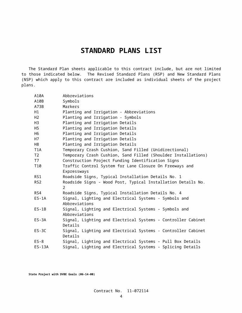
STANDARD PLANS LIST
The Standard Plan sheets applicable to this contract include, but are not limited to those indicated below. The Revised Standard Plans (RSP) and New Standard Plans (NSP) which apply to this contract are included as individual sheets of the project plans.
A10A AbbreviationsA10B SymbolsA73B MarkersH1 Planting and Irrigation - AbbreviationsH2 Planting and Irrigation - SymbolsH3 Planting and Irrigation DetailsH5 Planting and Irrigation DetailsH6 Planting and Irrigation DetailsH7 Planting and Irrigation DetailsH8 Planting and Irrigation DetailsT1A Temporary Crash Cushion, Sand Filled (Unidirectional)T2 Temporary Crash Cushion, Sand Filled (Shoulder Installations)T7 Construction Project Funding Identification SignsT10 Traffic Control System for Lane Closure On Freeways and ExpresswaysRS1 Roadside Signs, Typical Installation Details No. 1RS2 Roadside Signs - Wood Post, Typical Installation Details No. 2RS4 Roadside Signs, Typical Installation Details No. 4ES-1A Signal, Lighting and Electrical Systems - Symbols and AbbreviationsES-1B Signal, Lighting and Electrical Systems - Symbols and AbbreviationsES-3A Signal, Lighting and Electrical Systems - Controller Cabinet DetailsES-3C Signal, Lighting and Electrical Systems - Controller Cabinet DetailsES-8 Signal, Lighting and Electrical Systems - Pull Box DetailsES-13A Signal, Lighting and Electrical Systems - Splicing Details
Contract No. 11-0721143
State Project with DVBE Goals (06-14-00)
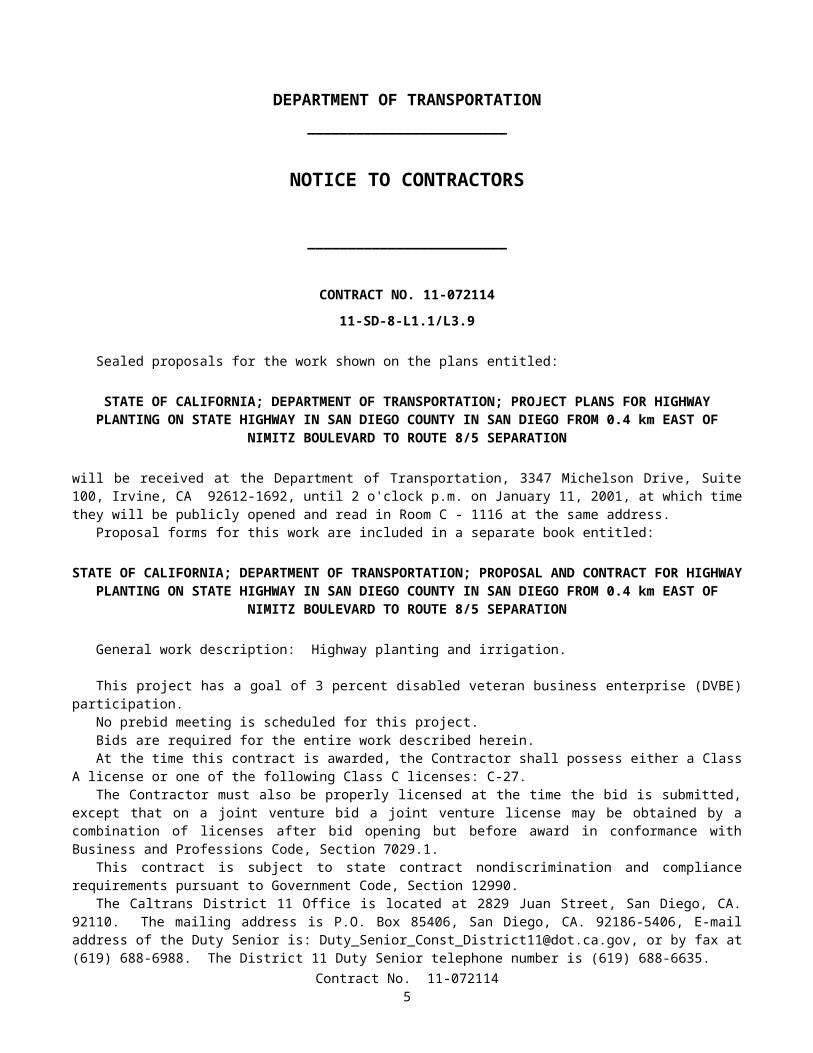
DEPARTMENT OF TRANSPORTATION_________________________
NOTICE TO CONTRACTORS
_________________________
CONTRACT NO. 11-072114
11-SD-8-L1.1/L3.9
Sealed proposals for the work shown on the plans entitled:
STATE OF CALIFORNIA; DEPARTMENT OF TRANSPORTATION; PROJECT PLANS FOR HIGHWAY PLANTING ON STATE HIGHWAY IN SAN DIEGO COUNTY IN SAN DIEGO FROM 0.4 km EAST OF NIMITZ
BOULEVARD TO ROUTE 8/5 SEPARATION
will be received at the Department of Transportation, 3347 Michelson Drive, Suite 100, Irvine, CA 92612-1692, until 2 o'clock p.m. on January 11, 2001, at which time they will be publicly opened and read in Room C - 1116 at the same address.
Proposal forms for this work are included in a separate book entitled:
STATE OF CALIFORNIA; DEPARTMENT OF TRANSPORTATION; PROPOSAL AND CONTRACT FOR HIGHWAY PLANTING ON STATE HIGHWAY IN SAN DIEGO COUNTY IN SAN DIEGO FROM 0.4 km EAST
OF NIMITZ BOULEVARD TO ROUTE 8/5 SEPARATION
General work description: Highway planting and irrigation.
This project has a goal of 3 percent disabled veteran business enterprise (DVBE) participation.No prebid meeting is scheduled for this project.Bids are required for the entire work described herein.At the time this contract is awarded, the Contractor shall possess either a Class A license or one of the following Class C
licenses: C-27.The Contractor must also be properly licensed at the time the bid is submitted, except that on a joint venture bid a joint
venture license may be obtained by a combination of licenses after bid opening but before award in conformance with Business and Professions Code, Section 7029.1.
This contract is subject to state contract nondiscrimination and compliance requirements pursuant to Government Code, Section 12990.
The Caltrans District 11 Office is located at 2829 Juan Street, San Diego, CA. 92110. The mailing address is P.O. Box 85406, San Diego, CA. 92186-5406, E-mail address of the Duty Senior is: [email protected], or by fax at (619) 688-6988. The District 11 Duty Senior telephone number is (619) 688-6635.
The Website address for posting of questions and responses is: www.dot.ca.gov/dist11/construc/Preference will be granted to bidders properly certified as a "Small Business" as determined by the Department of
General Services, Office of Small Business Certification and Resources at the time of bid opening in conformance with the provisions in Section 2-1.05, "Small Business Preference," of the special provisions, and Section 1896 et seq, Title 2, California Code of Regulations. A form for requesting a "Small Business" preference is included with the bid documents. Applications for status as a "Small Business" must be submitted to the Department of General Services, Office of Small Business Certification and Resources, 1531 "I" Street, Second Floor, Sacramento, CA 95814, Telephone No. (916) 322-5060.
Contract No. 11-0721144
A reciprocal preference will be granted to "California company" bidders in conformance with Section 6107 of the Public Contract Code. (See Sections 2 and 3 of the special provisions.) A form for indicating whether bidders are or are not a "California company" is included in the bid documents and is to be filled in and signed by all bidders.
Project plans, special provisions, and proposal forms for bidding this project can only be obtained at the Department of Transportation, Plans and Bid Documents, Room 0200, MS #26, Transportation Building, 1120 N Street, Sacramento, California 95814, FAX No. (916) 654-7028, Telephone No. (916) 654-4490. Use FAX orders to expedite orders for project plans, special provisions and proposal forms. FAX orders must include credit card charge number, card expiration date and authorizing signature. Project plans, special provisions, and proposal forms may be seen at the above Department of Transportation office and at the offices of the District Directors of Transportation at Irvine, Oakland, and the district in which the work is situated. Standard Specifications and Standard Plans are available through the State of California, Department of Transportation, Publications Unit, 1900 Royal Oaks Drive, Sacramento, CA 95815, Telephone No. (916) 445-3520.
Cross sections for this project are not available.The successful bidder shall furnish a payment bond and a performance bond.
Pursuant to Section 1773 of the Labor Code, the general prevailing wage rates in the county, or counties, in which the work is to be done have been determined by the Director of the California Department of Industrial Relations. These wages are set forth in the General Prevailing Wage Rates for this project, available at the Labor Compliance Office at the offices of the District Director of Transportation for the district in which the work is situated, and available from the California Department of Industrial Relations’ Internet Web Site at: http://www.dir.ca.gov. Future effective general prevailing wage rates which have been predetermined and are on file with the Department of Industrial Relations are referenced but not printed in the general prevailing wage rates.
DEPARTMENT OF TRANSPORTATION
Deputy Director Transportation Engineering
Dated December 11, 2000
GAB
Contract No. «Dist»-«Contract_No»1
COPY OF ENGINEER'S ESTIMATE
(NOT TO BE USED FOR BIDDING PURPOSES)
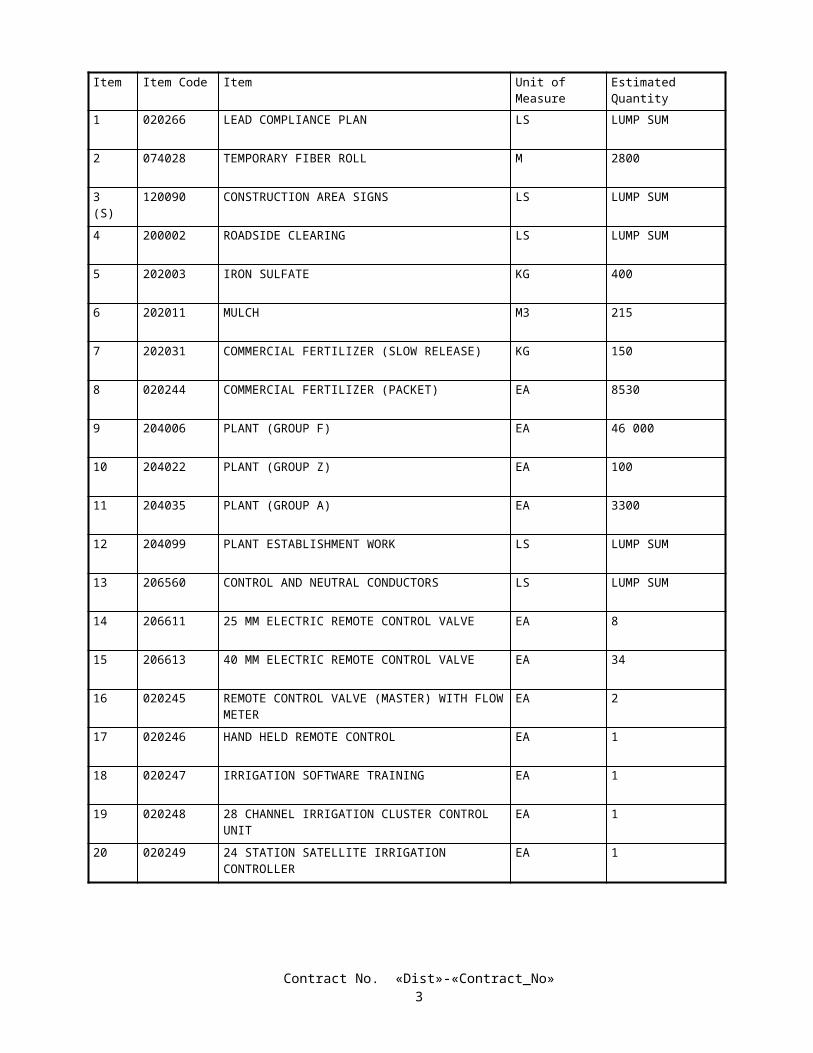
11-072114Item Item Code Item Unit of Measure Estimated Quantity
1 020266 LEAD COMPLIANCE PLAN LS LUMP SUM
2 074028 TEMPORARY FIBER ROLL M 2800
3(S)
120090 CONSTRUCTION AREA SIGNS LS LUMP SUM
4 200002 ROADSIDE CLEARING LS LUMP SUM
5 202003 IRON SULFATE KG 400
6 202011 MULCH M3 215
7 202031 COMMERCIAL FERTILIZER (SLOW RELEASE) KG 150
8 020244 COMMERCIAL FERTILIZER (PACKET) EA 8530
9 204006 PLANT (GROUP F) EA 46 000
10 204022 PLANT (GROUP Z) EA 100
11 204035 PLANT (GROUP A) EA 3300
12 204099 PLANT ESTABLISHMENT WORK LS LUMP SUM
13 206560 CONTROL AND NEUTRAL CONDUCTORS LS LUMP SUM
14 206611 25 MM ELECTRIC REMOTE CONTROL VALVE EA 8
15 206613 40 MM ELECTRIC REMOTE CONTROL VALVE EA 34
16 020245 REMOTE CONTROL VALVE (MASTER) WITH FLOW METER
EA 2
17 020246 HAND HELD REMOTE CONTROL EA 1
18 020247 IRRIGATION SOFTWARE TRAINING EA 1
19 020248 28 CHANNEL IRRIGATION CLUSTER CONTROL UNIT
EA 1
20 020249 24 STATION SATELLITE IRRIGATION CONTROLLER
EA 1
Contract No. «Dist»-«Contract_No»2
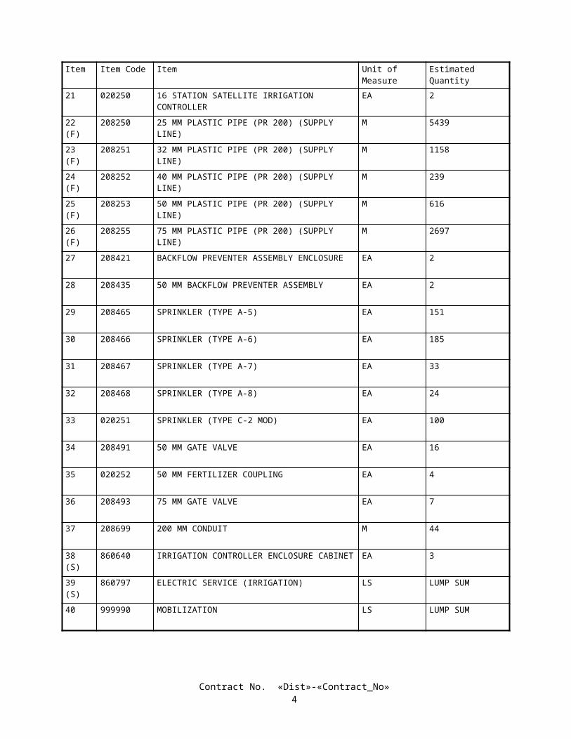
Item Item Code Item Unit of Measure Estimated Quantity
21 020250 16 STATION SATELLITE IRRIGATION CONTROLLER
EA 2
22(F)
208250 25 MM PLASTIC PIPE (PR 200) (SUPPLY LINE) M 5439
23(F)
208251 32 MM PLASTIC PIPE (PR 200) (SUPPLY LINE) M 1158
24(F)
208252 40 MM PLASTIC PIPE (PR 200) (SUPPLY LINE) M 239
25(F)
208253 50 MM PLASTIC PIPE (PR 200) (SUPPLY LINE) M 616
26(F)
208255 75 MM PLASTIC PIPE (PR 200) (SUPPLY LINE) M 2697
27 208421 BACKFLOW PREVENTER ASSEMBLY ENCLOSURE EA 2
28 208435 50 MM BACKFLOW PREVENTER ASSEMBLY EA 2
29 208465 SPRINKLER (TYPE A-5) EA 151
30 208466 SPRINKLER (TYPE A-6) EA 185
31 208467 SPRINKLER (TYPE A-7) EA 33
32 208468 SPRINKLER (TYPE A-8) EA 24
33 020251 SPRINKLER (TYPE C-2 MOD) EA 100
34 208491 50 MM GATE VALVE EA 16
35 020252 50 MM FERTILIZER COUPLING EA 4
36 208493 75 MM GATE VALVE EA 7
37 208699 200 MM CONDUIT M 44
38(S)
860640 IRRIGATION CONTROLLER ENCLOSURE CABINET EA 3
39(S)
860797 ELECTRIC SERVICE (IRRIGATION) LS LUMP SUM
40 999990 MOBILIZATION LS LUMP SUM
Contract No. «Dist»-«Contract_No»3
STATE OF CALIFORNIA
DEPARTMENT OF TRANSPORTATION
_____________________________
SPECIAL PROVISIONS
Annexed to Contract No. 11-072114
SECTION 1. SPECIFICATIONS AND PLANSThe work embraced herein shall conform to the provisions in the Standard Specifications dated July 1999, and the
Standard Plans dated July 1999, of the Department of Transportation insofar as the same may apply, and these special provisions.
Amendments to the Standard Specifications set forth in these special provisions shall be considered as part of the Standard Specifications for the purposes set forth in Section 5-1.04, "Coordination and Interpretation of Plans, Standard Specifications and Special Provisions," of the Standard Specifications. Whenever either the term "Standard Specifications is amended" or the term "Standard Specifications are amended" is used in the special provisions, the indented text or table following the term shall be considered an amendment to the Standard Specifications. In case of conflict between such amendments and the Standard Specifications, the amendments shall take precedence over and be used in lieu of the conflicting portions.
In case of conflict between the Standard Specifications and these special provisions, the special provisions shall take precedence over and shall be used in lieu of the conflicting portions.
SECTION 2. PROPOSAL REQUIREMENTS AND CONDITIONS2-1.01 GENERAL
The bidder's attention is directed to the provisions in Section 2, "Proposal Requirements and Conditions," of the Standard Specifications and these special provisions for the requirements and conditions which the bidder must observe in the preparation of the proposal form and the submission of the bid.
In addition to the subcontractors required to be listed in conformance with Section 2-1.054, "Required Listing of Proposed Subcontractors," of the Standard Specifications, each proposal shall have listed therein the name and address of each DVBE subcontractor to be used for credit in meeting the goal, and to whom the bidder proposes to directly subcontract portions of the work. The list of subcontractors shall also set forth the portion of work that will be performed by each subcontractor listed. A sheet for listing the subcontractors is included in the Proposal.
The Bidder's Bond form mentioned in the last paragraph in Section 2-1.07, "Proposal Guaranty," of the Standard Specifications will be found following the signature page of the Proposal.
In conformance with Public Contract Code Section 7106, a Noncollusion Affidavit is included in the Proposal. Signing the Proposal shall also constitute signature of the Noncollusion Affidavit.
Submit request for substitution of an "or equal" item, and the data substantiating the request to the Department of Transportation, District 11, Construction Duty Senior MS 73, P.O. Box 85406, San Diego, CA. 92186-5400, so that the request is received by the Department by close of business on the fourth day, not including Saturdays, Sundays and legal holidays, following bid opening.
2-1.02 DISABLED VETERAN BUSINESS ENTERPRISE (DVBE)Section 10115 of the Public Contract Code requires the Department to implement provisions to establish a goal for
Disabled Veterans Business Enterprise (DVBE) in contracts.It is the policy of the Department that Disabled Veteran Business Enterprise (DVBE) shall have the maximum
opportunity to participate in the performance of contracts financed solely with state funds. The Contractor shall ensure that DVBEs have the maximum opportunity to participate in the performance of this contract and shall take all necessary and reasonable steps for this assurance. The Contractor shall not discriminate on the basis of race, color, national origin, or sex in the award and performance of subcontracts. Failure to carry out the requirements of this paragraph shall constitute a breach of contract and may result in termination of this contract or other remedy the Department may deem appropriate.
Contract No. «Dist»-«Contract_No»4
Bidder's attention is directed to the following:
A. "Disabled Veteran Business Enterprise" (DVBE) means a business concern certified as a DVBE by the Office of Small Business Certification and Resources, Department of General Services.
B. A DVBE may participate as a prime contractor, subcontractor, joint venture partner with a prime or subcontractor, or vendor of material or supplies.
C. Credit for DVBE prime contractors will be 100 percent.D. A DVBE joint venture partner must be responsible for specific contract items of work, or portions thereof.
Responsibility means actually performing, managing and supervising the work with its own forces. The DVBE joint venture partner must share in the ownership, control, management responsibilities, risks and profits of the joint venture. The DVBE joint venturer must submit the joint venture agreement with the Caltrans Bidder DVBE Information form required in Section 2-1.04, "Submission of DVBE Information," elsewhere in these special provisions.
E. A DVBE must perform a commercially useful function, i.e., must be responsible for the execution of a distinct element of the work and must carry out its responsibility by actually performing, managing and supervising the work.
F. Credit for DVBE vendors of materials or supplies is limited to 60 percent of the amount to be paid to the vendor for the material unless the vendor manufactures or substantially alters the goods.
G. Credit for trucking by DVBEs will be as follows:
1. One hundred percent of the amount to be paid when a DVBE trucker will perform the trucking with his/her own trucks, tractors and employees.
2. Twenty percent of the amount to be paid to DVBE trucking brokers who do not have a "certified roster."3. One hundred percent of the amount to be paid to DVBE trucking brokers who have signed agreements that all
trucking will be performed by DVBE truckers if credit is toward the DVBE goal, a "certified roster" showing that all trucks are owned by DVBEs, and a signed statement on the "certified roster" that indicates that 100 percent of revenue paid by the broker will be paid to the DVBEs listed on the "certified roster."
4. Twenty percent of the amount to be paid to trucking brokers who are not a DVBE but who have signed agreements with DVBE truckers assuring that at least 20 percent of the trucking will be performed by DVBE truckers if credit is toward the DVBE goal, a "certified roster" showing that at least 20 percent of the number of trucks are owned by DVBE truckers, and a signed statement on the "certified roster" that indicates that at least 20 percent of the revenue paid by the broker will be paid to the DVBEs listed on the "certified roster."
The "certified roster" referred to herein shall conform to the requirements in Section 2-1.04, "Submission Of DVBE Information," elsewhere in these special provisions.
H. DVBEs and DVBE joint venture partners must be certified DVBEs as determined by the Department of General Services, Office of Small Business Certification and Resources, 1531 "I" Street, Second Floor, Sacramento, CA 95814, on the date bids for the project are opened before credit may be allowed toward the DVBE goal. It is the Contractor's responsibility to verify that DVBEs are certified.
I. Noncompliance by the Contractor with these requirements constitutes a breach of this contract and may result in termination of the contract or other appropriate remedy for a breach of this contract.
2-1.03 DVBE GOAL FOR THIS PROJECTThe Department has established the following goal for Disabled Veteran Business Enterprise (DVBE) participation for
this project:
Disabled Veteran Business Enterprise (DVBE): 3 percent.
It is the bidder's responsibility to make a sufficient portion of the work available to subcontractors and suppliers and to select those portions of the work or material needs consistent with the available DVBE subcontractors and suppliers, so as to assure meeting the goal for DVBE participation.
The Office of Small Business Certification and Resources, Department of General Services, may be contacted at (916) 322-5060 or visit their internet web site at http://www.osmb.dgs.ca.gov/ for program information and certification status. The Department's Business Enterprise Program may also be contacted at (916) 227-9599 or the internet web site at http://www.dot.ca.gov/hq/bep/.
Contract No. «Dist»-«Contract_No»5
2-1.04 SUBMISSION OF DVBE INFORMATIONThe required DVBE information shall be submitted on the "CALTRANS BIDDER - DVBE INFORMATION" form
included in the Proposal. If this information is not submitted with the bid, the DVBE information forms shall be removed from the documents prior to submitting the bid.
It is the bidder's responsibility to make enough work available to DVBEs and to select those portions of the work or material needs consistent with the available DVBEs to meet the goal for DVBE participation or to provide information to establish that, prior to bidding, the bidder made adequate good faith efforts to do so.
If the DVBE information is not submitted with the bid, the apparent successful bidder (low bidder), the second low bidder and the third low bidder shall submit the DVBE information to the Department of Transportation, 1120 N Street, Room 0200, MS #26, Sacramento, California 95814 so the information is received by the Department no later than 4:00 p.m. on the fourth day, not including Saturdays, Sundays and legal holidays, following bid opening. DVBE information sent by U.S. Postal Service certified mail with return receipt and certificate of mailing and mailed on or before the third day, not including Saturdays, Sundays and legal holidays, following bid opening will be accepted even if it is received after the fourth day following bid opening. Failure to submit the required DVBE information by the time specified will be grounds for finding the bid or proposal nonresponsive. Other bidders need not submit DVBE information unless requested to do so by the Department.
The bidder's DVBE information shall establish that good faith efforts to meet the DVBE goal have been made. To establish good faith efforts, the bidder shall demonstrate that the goal will be met or that, prior to bidding, adequate good faith efforts to meet the goal were made.
Bidders are cautioned that even though their submittal indicates they will meet the stated DVBE goal, their submittal should also include their adequate good faith efforts information along with their DVBE goal information to protect their eligibility for award of the contract in the event the Department, in its review, finds that the goal has not been met.
The bidder's DVBE information shall include the names of DVBE firms that will participate, with a complete description of work or supplies to be provided by each, the dollar value of each DVBE transaction, and a written confirmation from the DVBE that it is participating in the contract. A copy of the DVBE's quote will serve as written confirmation that the DVBE is participating in the contract. When 100 percent of a contract item of work is not to be performed or furnished by a DVBE, a description of the exact portion of that work to be performed or furnished by that DVBE shall be included in the DVBE information, including the planned location of that work. The work that a DVBE prime contractor has committed to performing with its own forces as well as the work that it has committed to be performed by DVBE subcontractors, suppliers and trucking companies will count toward the goal.
If credit for trucking by a DVBE trucking broker is shown on the bidder's information as 100 percent of the revenue to be paid by the broker is to be paid to DVBE truckers, a "certified roster" of the broker's trucks to be used must be included. The "certified roster" must indicate that all the trucks are owned by certified DVBEs and must show the DVBE truck numbers, owner's name, Public Utilities Commission Cal-T numbers, and the DVBE certification numbers. The roster must indicate that all revenue paid by the broker will be paid to DVBEs listed on the "certified roster".
If credit for trucking by a trucking broker who is not a DVBE is shown in the bidder's information, a "certified roster" of the broker's trucks to be used must be included. The "certified roster" must indicate that at least 20 percent of the broker's trucks are owned by certified DVBEs and must show the DVBE truck numbers, owner's name, Public Utilities Commission Cal-T numbers, and the DVBE certification number. The roster must indicate that at least 20 percent of the revenue paid by the broker will be paid to DVBEs listed on the "certified roster".
A bidder shall be deemed to have made good faith efforts upon submittal, within time limits specified by the Department, of documentary evidence that all of the following actions were taken:
A. Contact was made with the Office of Small Business Certification and Resources (OSBCR), Department of General Services or their web site at http://www.osmb.dgs.ca.gov/ to identify Disabled Veteran Business Enterprises.
B. Advertising was published in trade media and media focusing on Disabled Veteran Business Enterprises, unless time limits imposed by the Department do not permit that advertising.
C. Invitations to bid were submitted to potential Disabled Veteran Business Enterprise contractors.D. Available Disabled Veteran Business Enterprises were considered.
2-1.05 SMALL BUSINESS PREFERENCEAttention is directed to "Award and Execution of Contract" of these special provisions.Attention is also directed to the Small Business Procurement and Contract Act, Government Code Section 14835, et seq
and Title 2, California Code of Regulations, Section 1896, et seq.Bidders who wish to be classified as a Small Business under the provisions of those laws and regulations, shall be
certified as Small Business by the Department of General Services, Office of Small Business Certification and Resources, 1531 "I" Street, Second Floor, Sacramento, CA 95814.
Contract No. «Dist»-«Contract_No»6
To request Small Business Preference, bidders shall fill out and sign the Request for Small Business Preference form in the Proposal and shall attach a copy of their Office of Small Business Certification and Resources (OSBCR) small business certification letter to the form. The bidder's signature on the Request for Small Business Preference certifies, under penalty of perjury, that the bidder is certified as Small Business at the time of bid opening and further certifies, under penalty of perjury, that under the following conditions, at least 50 percent of the subcontractors to be utilized on the project are either certified Small Business or have applied for Small Business certification by bid opening date and are subsequently granted Small Business certification.
The conditions requiring the aforementioned 50 percent level of subcontracting by Small Business subcontractors apply if:
A. The lowest responsible bid for the project exceeds $100,000; andB. The project work to be performed requires a Class A or a Class B contractor's license; andC. Two or more subcontractors will be used.
If the above conditions apply and Small Business Preference is granted in the award of the contract, the 50 percent Small Business subcontractor utilization level shall be maintained throughout the life of the contract.
2-1.06 CALIFORNIA COMPANY PREFERENCEAttention is directed to "Award and Execution of Contract" of these special provisions.In conformance with the requirements of Section 6107 of the Public Contract Code, a "California company" will be
granted a reciprocal preference for bid comparison purposes as against a nonresident contractor from any state that gives or requires a preference to be given contractors from that state on its public entity construction contracts.
A "California company" means a sole proprietorship, partnership, joint venture, corporation, or other business entity that was a licensed California contractor on the date when bids for the public contract were opened and meets one of the following:
A. Has its principal place of business in California.B. Has its principal place of business in a state in which there is no local contractor preference on construction
contracts.C. Has its principal place of business in a state in which there is a local contractor construction preference and the
contractor has paid not less than $5000 in sales or use taxes to California for construction related activity for each of the five years immediately preceding the submission of the bid.
To carry out the "California company" reciprocal preference requirements of Section 6107 of the Public Contract Code, all bidders shall fill out and sign the California Company Preference form in the Proposal. The bidder's signature on the California Company Preference form certifies, under penalty of perjury, that the bidder is or is not a "California company" and if not, the amount of the preference applied by the state of the nonresident Contractor.
A nonresident Contractor shall disclose any and all bid preferences provided to the nonresident Contractor by the state or country in which the nonresident Contractor has its principal place of business.
Proposals without the California Company Preference form filled out and signed may be rejected.
SECTION 3. AWARD AND EXECUTION OF CONTRACTThe bidder's attention is directed to the provisions in Section 3, "Award and Execution of Contract," of the Standard
Specifications and these special provisions for the requirements and conditions concerning award and execution of contract.The contract shall be signed by the successful bidder and returned, together with the contract bonds, within 4 days, not
including Saturdays, Sundays and legal holidays, after the bidder has received notice that the contract has been awarded. Failure to do so shall be just cause for forfeiture of the proposal guaranty. The executed contract documents shall be delivered to the following address: Department of Transportation, P.O. Box 942874, Sacramento, CA 94274-0001, Attn.: Office Engineer (MS43) - Contracts.
The award of the contract, if it be awarded, will be to the lowest responsible bidder whose proposal complies with all the requirements prescribed and who has met the goal for DVBE participation or has demonstrated, to the satisfaction of the Department, adequate good faith efforts to do so. Meeting the goal for DVBE participation or demonstrating, to the satisfaction of the Department, adequate good faith efforts to do so is a condition for being eligible for award of contract.
A "Payee Data Record" form will be included in the contract documents to be executed by the successful bidder. The purpose of the form is to facilitate the collection of taxpayer identification data. The form shall be completed and returned to the Department by the successful bidder with the executed contract and contract bonds. For the purposes of the form, payee shall be deemed to mean the successful bidder. The form is not to be completed for subcontractors or suppliers. Failure to complete and return the "Payee Data Record" form to the Department as provided herein will result in the retention of
Contract No. «Dist»-«Contract_No»7
20 percent of payments due the contractor and penalties of up to $20,000. This retention of payments for failure to complete the "Payee Data Record" form is in addition to any other retention of payments due the Contractor.
Attention is also directed to "Small Business Preference" of these special provisions. Any bidder who is certified as a Small Business by the Department of General Services, Office of Small Business Certification and Resources will be allowed a preference in the award of this contract, if it be awarded, under the following conditions:
A. The apparent low bidder is not certified as a Small Business, or has not filled out and signed the Request for Small Business Preference included with the bid documents and attached a copy of their Office of Small Business Certification and Resources (OSBCR) small business certification letter to the form; and
B. The bidder filled out and signed the Request for Small Business Preference form included with the bid documents and attached a copy of their Office of Small Business Certification and Resources (OSBCR) small business certification letter to the form.
The small business preference will be a reduction in the bid submitted by the small business contractor, for bid comparison purposes, by an amount equal to 5 percent of the amount bid by the apparent low bidder, the amount not to exceed $50,000. If this reduction results in the small business contractor becoming the low bidder, then the contract will be awarded to the small business contractor on the basis of the actual bid of the small business contractor notwithstanding the reduced bid price used for bid comparison purposes.
Attention is also directed to "California Company Preference" of these special provisions.The amount of the California company reciprocal preference shall be equal to the amount of the preference applied by
the state of the nonresident contractor with the lowest responsive bid, except where the "California company" is eligible for a California Small Business Preference, in which case the preference applied shall be the greater of the two, but not both.
If the bidder submitting the lowest responsive bid is not a "California company" and with the benefit of the reciprocal preference, a "California company's" responsive bid is equal to or less than the original lowest responsive bid, the "California company" will be awarded the contract at its submitted bid price except as provided below.
Small business bidders shall have precedence over nonsmall business bidders in that the application of the "California company" preference for which nonsmall business bidders may be eligible shall not result in the denial of the award to a small business bidder.
SECTION 4. BEGINNING OF WORK, TIME OF COMPLETION AND LIQUIDATED DAMAGESAttention is directed to the provisions in Section 8-1.03, "Beginning of Work," in Section 8-1.06, "Time of Completion,"
and in Section 8-1.07, "Liquidated Damages," of the Standard Specifications and these special provisions.The Contractor shall begin work within 5 calendar days after the contract has been approved by the Attorney General or
the attorney appointed and authorized to represent the Department of Transportation.The work shall be diligently prosecuted to completion before the expiration of
560 WORKING DAYS
beginning on the fifth calendar day after approval of the contract.The Contractor shall pay to the State of California the sum of $ 325 per day, for each and every calendar day's delay in
finishing the work in excess of the number of working days prescribed above.
SECTION 5. GENERALSECTION 5-1. MISCELLANEOUS
5-1.01 PLANS AND WORKING DRAWINGSWhen the specifications require working drawings to be submitted to the Division of Structure Design, the drawings
shall be submitted to: Division of Structure Design, Documents Unit, Mail Station 9, 1801 30th Street, Sacramento, CA 95816, Telephone 916 227-8252.
5-1.011 EXAMINATION OF PLANS, SPECIFICATIONS, CONTRACT, AND SITE OF WORKThe second paragraph of Section 2-1.03, "Examination of Plans, Specifications, Contract, and Site of Work," of the
Standard Specifications is amended to read:
• Where the Department has made investigations of site conditions, including subsurface conditions in areas where work is to be performed under the contract, or in other areas, some of which may constitute possible local material
Contract No. «Dist»-«Contract_No»8
sources, bidders or Contractors may, upon written request, inspect the records of the Department as to those investigations subject to and upon the conditions hereinafter set forth.
Attention is directed to "Differing Site Conditions" of these special provisions regarding physical conditions at the site which may differ from those indicated in "Materials Information," log of test borings or other geotechnical information obtained by the Department's investigation of site conditions.
5-1.012 DIFFERING SITE CONDITIONSAttention is directed to Section 5-1.116, "Differing Site Conditions," of the Standard Specifications.During the progress of the work, if subsurface or latent conditions are encountered at the site differing materially from
those indicated in the "Materials Information," log of test borings, other geotechnical data obtained by the Department's investigation of subsurface conditions, or an examination of the conditions above ground at the site, the party discovering those conditions shall promptly notify the other party in writing of the specific differing conditions before they are disturbed and before the affected work is performed.
The Contractor will be allowed 15 days from the notification of the Engineer's determination of whether or not an adjustment of the contract is warranted, in which to file a notice of potential claim in conformance with the provisions of Section 9-1.04, "Notice of Potential Claim," of the Standard Specifications and as specified herein; otherwise the decision of the Engineer shall be deemed to have been accepted by the Contractor as correct. The notice of potential claim shall set forth in what respects the Contractor's position differs from the Engineer's determination and provide any additional information obtained by the Contractor, including but not limited to additional geotechnical data. The notice of potential claim shall be accompanied by the Contractor's certification that the following were made in preparation of the bid: a review of the contract, a review of the "Materials Information," a review of the log of test borings and other records of geotechnical data to the extent they were made available to bidders prior to the opening of bids, and an examination of the conditions above ground at the site. Supplementary information, obtained by the Contractor subsequent to the filing of the notice of potential claim, shall be submitted to the Engineer in an expeditious manner.
5-1.015 LABORATORYWhen a reference is made in the specifications to the "Laboratory," the reference shall mean the Division of Materials
Engineering and Testing Services and the Division of Structural Foundations of the Department of Transportation, or established laboratories of the various Districts of the Department, or other laboratories authorized by the Department to test materials and work involved in the contract. When a reference is made in the specifications to the "Transportation Laboratory," the reference shall mean the Division of Materials Engineering and Testing Services and the Division of Structural Foundations, located at 5900 Folsom Boulevard, Sacramento, CA 95819, Telephone (916) 227-7000.
5-1.017 CONTRACT BONDSAttention is directed to Section 3-1.02, "Contract Bonds," of the Standard Specifications and these special provisions.The payment bond shall be in a sum not less than the following:
A. One hundred percent of the total amount payable by the terms of the contract when the total amount payable does not equal or exceed five million dollars ($5,000,000).
B. Fifty percent of the total amount payable by the terms of the contract when the total amount payable is not less than five million dollars ($5,000,000) and does not exceed ten million dollars ($10,000,000).
C. Twenty-five percent of the total amount payable by the terms of the contract when the total amount payable exceeds ten million dollars ($10,000,000).
5-1.018 EXCAVATION SAFETY PLANSSection 5-1.02A, "Trench Excavation Safety Plans," of the Standard Specifications is amended to read:
5-1.02A Excavation Safety Plans• The Construction Safety Orders of the Division of Occupational Safety and Health shall apply to all excavations. For all excavations 1.5 m or more in depth, the Contractor shall submit to the Engineer a detailed plan showing the design and details of the protective systems to be provided for worker protection from the hazard of caving ground during excavation. The detailed plan shall include any tabulated data and any design calculations used in the preparation of the plan. Excavation shall not begin until the detailed plan has been reviewed and approved by the Engineer.• Detailed plans of protective systems for which the Construction Safety Orders require design by a registered professional engineer shall be prepared and signed by an engineer who is registered as a Civil Engineer in the State
Contract No. «Dist»-«Contract_No»9
of California, and shall include the soil classification, soil properties, soil design calculations that demonstrate adequate stability of the protective system, and any other design calculations used in the preparation of the plan.• No plan shall allow the use of a protective system less effective than that required by the Construction Safety Orders.• If the detailed plan includes designs of protective systems developed only from the allowable configurations and slopes, or Appendices, contained in the Construction Safety Orders, the plan shall be submitted at least 5 days before the Contractor intends to begin excavation. If the detailed plan includes designs of protective systems developed from tabulated data, or designs for which design by a registered professional engineer is required, the plan shall be submitted at least 3 weeks before the Contractor intends to begin excavation.• Attention is directed to Section 7-1.01E, "Trench Safety."
The third paragraph of Section 19-1.02, "Preservation of Property," of the Standard Specifications is amended to read:
• In addition to the provisions in Sections 5-1.02, "Plans and Working Drawings," and 5-1.02A, "Excavation Safety Plans," detailed plans of the protective systems for excavations on or affecting railroad property will be reviewed for adequacy of protection provided for railroad facilities, property, and traffic. These plans shall be submitted at least 9 weeks before the Contractor intends to begin excavation requiring the protective systems. Approval by the Engineer of the detailed plans for the protective systems will be contingent upon the plans being satisfactory to the railroad company involved.
5-1.02 LABOR NONDISCRIMINATIONAttention is directed to the following Notice that is required by Chapter 5 of Division 4 of Title 2, California Code of
Regulations.
NOTICE OF REQUIREMENT FOR NONDISCRIMINATION PROGRAM (GOV. CODE, SECTION 12990)
Your attention is called to the "Nondiscrimination Clause", set forth in Section 7-1.01A(4), "Labor Nondiscrimination," of the Standard Specifications, which is applicable to all nonexempt State contracts and subcontracts, and to the "Standard California Nondiscrimination Construction Contract Specifications" set forth therein. The specifications are applicable to all nonexempt State construction contracts and subcontracts of $5000 or more.
5-1.03 INTEREST ON PAYMENTSInterest shall be payable on progress payments, payments after acceptance, final payments, extra work payments, and
claim payments as follows:
A. Unpaid progress payments, payment after acceptance, and final payments shall begin to accrue interest 30 days after the Engineer prepares the payment estimate.
B. Unpaid extra work bills shall begin to accrue interest 30 days after preparation of the first pay estimate following receipt of a properly submitted and undisputed extra work bill. To be properly submitted, the bill must be submitted within 7 days of the performance of the extra work and in conformance with the provisions in Section 9 -1.03C, "Records," and Section 9-1.06, "Partial Payments," of the Standard Specifications. An undisputed extra work bill not submitted within 7 days of performance of the extra work will begin to accrue interest 30 days after the preparation of the second pay estimate following submittal of the bill.
C. The rate of interest payable for unpaid progress payments, payments after acceptance, final payments, and extra work payments shall be 10 percent per annum.
D. The rate of interest payable on a claim, protest or dispute ultimately allowed under this contract shall be 6 percent per annum. Interest shall begin to accrue 61 days after the Contractor submits to the Engineer information in sufficient detail to enable the Engineer to ascertain the basis and amount of said claim, protest or dispute.
The rate of interest payable on any award in arbitration shall be 6 percent per annum if allowed under the provisions of Civil Code Section 3289.
5-1.031 FINAL PAYMENT AND CLAIMSAttention is directed to Section 9-1.07B, "Final Payment and Claims," of the Standard Specifications.The District that administers the contract shall submit a claim position letter to the Contractor within 135 days after
acceptance of the contract. After receipt of the claim position letter from the District, or 135 days after acceptance of the contract, whichever occurs first, the Contractor may request a meeting with the person or board designated by the District
Contract No. «Dist»-«Contract_No»10
Director to review claims that remain in dispute. If the Contractor requests a meeting, the review person or board shall meet with the Contractor within 45 days after the request is received.
5-1.04 PUBLIC SAFETYThe Contractor shall provide for the safety of traffic and the public in conformance with the provisions in Section 7 -1.09,
"Public Safety," of the Standard Specifications and these special provisions.The Contractor shall install temporary railing (Type K) between a lane open to public traffic and an excavation, obstacle
or storage area when the following conditions exist:
A. Excavations.—The near edge of the excavation is 3.6 m or less from the edge of the lane, except:
1. Excavations covered with sheet steel or concrete covers of adequate thickness to prevent accidental entry by traffic or the public.
2. Excavations less than 0.3-m deep.3. Trenches less than 0.3-m wide for irrigation pipe or electrical conduit, or excavations less than 0.3-m in
diameter.4. Excavations parallel to the lane for the purpose of pavement widening or reconstruction.5. Excavations in side slopes, where the slope is steeper than 1:4 (vertical:horizontal).6. Excavations protected by existing barrier or railing.
B. Temporarily Unprotected Permanent Obstacles.—The work includes the installation of a fixed obstacle together with a protective system, such as a sign structure together with protective railing, and the Contractor elects to install the obstacle prior to installing the protective system; or the Contractor, for the Contractor's convenience and with permission of the Engineer, removes a portion of an existing protective railing at an obstacle and does not replace such railing complete in place during the same day.
C. Storage Areas.—Material or equipment is stored within 3.6 m of the lane and the storage is not otherwise prohibited by the provisions of the Standard Specifications and these special provisions.
The approach end of temporary railing (Type K), installed in conformance with the provisions in this section "Public Safety" and in Section 7-1.09, "Public Safety," of the Standard Specifications, shall be offset a minimum of 4.6 m from the edge of the traffic lane open to public traffic. The temporary railing shall be installed on a skew toward the edge of the traffic lane of not more than 0.3-m transversely to 3 m longitudinally with respect to the edge of the traffic lane. If the 4.6 -m minimum offset cannot be achieved, the temporary railing shall be installed on the 10 to 1 skew to obtain the maximum available offset between the approach end of the railing and the edge of the traffic lane, and an array of temporary crash cushion modules shall be installed at the approach end of the temporary railing.
Temporary railing (Type K) shall conform to the provisions in Section 12-3.08, "Temporary Railing (Type K)," of the Standard Specifications. Temporary railing (Type K), conforming to the details shown on 1999 Standard Plan T3, may be used. Temporary railing (Type K) fabricated prior to January 1, 1993, and conforming to 1988 Standard Plan B11-30 may be used, provided the fabrication date is printed on the required Certificate of Compliance.
Temporary crash cushion modules shall conform to the provisions in "Temporary Crash Cushion Module" of these special provisions.
Except for installing, maintaining and removing traffic control devices, whenever work is performed or equipment is operated in the following work areas, the Contractor shall close the adjacent traffic lane unless otherwise provided in the Standard Specifications and these special provisions:
Approach Speed of Public Traffic (Posted Limit) (Kilometers Per Hour)
Work Areas
Over 72 (45 Miles Per Hour) Within 1.8 m of a traffic lane but not on a traffic lane56 to 72 (35 to 45 Miles Per Hour) Within 0.9-m of a traffic lane but not on a traffic lane
The lane closure provisions of this section shall not apply if the work area is protected by permanent or temporary railing or barrier.
When traffic cones or delineators are used to delineate a temporary edge of a traffic lane, the line of cones or delineators shall be considered to be the edge of the traffic lane, however, the Contractor shall not reduce the width of an existing lane to less than 3 m without written approval from the Engineer.
When work is not in progress on a trench or other excavation that required closure of an adjacent lane, the traffic cones or portable delineators used for the lane closure shall be placed off of and adjacent to the edge of the traveled way. The spacing of the cones or delineators shall be not more than the spacing used for the lane closure.
Contract No. «Dist»-«Contract_No»11
Suspended loads or equipment shall not be moved nor positioned over public traffic or pedestrians.Full compensation for conforming to the provisions in this section "Public Safety," including furnishing and installing
temporary railing (Type K) and temporary crash cushion modules, shall be considered as included in the contract prices paid for the various items of work involved and no additional compensation will be allowed therefor.
5-1.05 SURFACE MINING AND RECLAMATION ACTAttention is directed to the Surface Mining and Reclamation Act of 1975, commencing in Public Resources Code,
Mining and Geology, Section 2710, which establishes regulations pertinent to surface mining operations, and to California Public Contract Code Section 10295.5.
Material from mining operations furnished for this project shall only come from permitted sites in compliance with California Public Contract Code Section 10295.5.
The requirements of this section shall apply to materials furnished for the project, except for acquisition of materials in conformance with the provisions in Section 4-1.05, "Use of Materials Found on the Work," of the Standard Specifications.
5-1.06 REMOVAL OF ASBESTOS AND HAZARDOUS SUBSTANCESWhen the presence of asbestos or hazardous substances are not shown on the plans or indicated in the specifications and
the Contractor encounters materials which the Contractor reasonably believes to be asbestos or a hazardous substance as defined in Section 25914.1 of the Health and Safety Code, and the asbestos or hazardous substance has not been rendered harmless, the Contractor may continue work in unaffected areas reasonably believed to be safe. The Contractor shall immediately cease work in the affected area and report the condition to the Engineer in writing.
In conformance with Section 25914.1 of the Health and Safety Code, removal of asbestos or hazardous substances including exploratory work to identify and determine the extent of the asbestos or hazardous substance will be performed by separate contract.
If delay of work in the area delays the current controlling operation, the delay will be considered a right of way delay and the Contractor will be compensated for the delay in conformance with the provisions in Section 8-1.09, "Right of Way Delays," of the Standard Specifications.
5-1.07 YEAR 2000 COMPLIANCEThis contract is subject to Year 2000 Compliance for automated devices in the State of California.Year 2000 compliance for automated devices in the State of California is achieved when embedded functions have or
create no logical or mathematical inconsistencies when dealing with dates prior to and beyond 1999. The year 2000 is recognized and processed as a leap year. The product shall operate accurately in the manner in which the product was intended for date operation without requiring manual intervention.
The Contractor shall provide the Engineer a Certificate of Compliance from the manufacturer in conformance with the provisions in Section 6-1.07, "Certificates of Compliance," of the Standard Specifications for all automated devices furnished for the project.
5-1.08 SUBCONTRACTOR AND DVBE RECORDSThe Contractor shall maintain records of all subcontracts entered into with certified DVBE subcontractors and records of
materials purchased from certified DVBE suppliers. The records shall show the name and business address of each DVBE subcontractor or vendor and the total dollar amount actually paid each DVBE subcontractor or vendor.
Upon completion of the contract, a summary of these records shall be prepared on Form CEM-2402 (S) and certified correct by the Contractor or the Contractor's authorized representative, and shall be furnished to the Engineer.
5-1.086 PERFORMANCE OF DVBE SUBCONTRACTORS AND SUPPLIERSThe DVBEs listed by the Contractor in response to the provisions in Section 2-1.04, "Submission of DVBE
Information," and Section 3, "Award and Execution of Contract," of these special provisions, which are determined by the Department to be certified DVBEs, shall perform the work and supply the materials for which they are listed, unless the Contractor has received prior written authorization to perform the work with other forces or to obtain the materials from other sources.
Authorization to utilize other forces or sources of materials may be requested for the following reasons:
A. The listed DVBE, after having had a reasonable opportunity to do so, fails or refuses to execute a written contract, when the written contract, based upon the general terms, conditions, plans and specifications for the project, or on the terms of the subcontractor's or supplier's written bid, is presented by the Contractor.
B. The listed DVBE becomes bankrupt or insolvent.C. The listed DVBE fails or refuses to perform the subcontract or furnish the listed materials.
Contract No. «Dist»-«Contract_No»12
D. The Contractor stipulated that a bond was a condition of executing a subcontract and the listed DVBE subcontractor fails or refuses to meet the bond requirements of the Contractor.
E. The work performed by the listed subcontractor is substantially unsatisfactory and is not in substantial conformance with the plans and specifications or the subcontractor is substantially delaying or disrupting the progress of the work.
F. The listed DVBE subcontractor is not licensed pursuant to the Contractor's License Law.G. It would be in the best interest of the State.
The Contractor shall not be entitled to payment for the work or material unless it is performed or supplied by the listed DVBE or by other forces (including those of the Contractor) pursuant to prior written authorization of the Engineer.
5-1.09 SUBCONTRACTINGAttention is directed to the provisions in Section 8-1.01, "Subcontracting," of the Standard Specifications, Section 2,
"Proposal Requirements and Conditions," Section 2-1.04, "Submission of DVBE Information," and Section 3, "Award and Execution of Contract," of these special provisions and these special provisions.
Pursuant to the provisions in Section 1777.1 of the Labor Code, the Labor Commissioner publishes and distributes a list of contractors ineligible to perform work as a subcontractor on a public works project. This list of debarred contractors is available from the Department of Industrial Relations web site at:
http://www.dir.ca.gov/DLSE/Debar.html.
The DVBE information furnished under Section 3-1.01A, "DVBE Information," of these special provisions is in addition to the subcontractor information required to be furnished in Section 8-1.01, "Subcontracting," and Section 2-1.054, "Required Listing of Proposed Subcontractors," of the Standard Specifications.
Section 10115 of the Public Contract Code requires the Department to implement provisions to establish a goal for Disabled Veteran Business Enterprise (DVBE) participation in highway contracts that are State funded. As a part of this requirement:
A. No substitution of a DVBE subcontractor shall be made at any time without the written consent of the Department, and
B. If a DVBE subcontractor is unable to perform successfully and is to be replaced, the Contractor shall make good faith efforts to replace the original DVBE subcontractor with another DVBE subcontractor.
The provisions in Section 2-1.02, "Disabled Veteran Business Enterprise (DVBE)," of these special provisions that DVBEs shall be certified on the date bids are opened does not apply to DVBE substitutions after award of the contract.
5-1.10 PROMPT PROGRESS PAYMENT TO SUBCONTRACTORSAttention is directed to the provisions in Sections 10262 and 10262.5 of the Public Contract Code and Section 7108.5 of
the Business and Professions Code concerning prompt payment to subcontractors.
5-1.11 ENVIRONMENTALLY SENSITIVE AREA (ESA)The Contractor's attention is directed to the areas designated on the plans as "Environmentally Sensitive Area," and to
certain State and Federal regulations which may pertain to such areas. These areas shall be completely avoided by all parties involved in any work activity in connection with the performance of this contract.
5-1.12 AREAS FOR CONTRACTOR'S USEAttention is directed to the provisions in Section 7-1.19, "Rights in Land and Improvements," of the Standard
Specifications and these special provisions.The highway right of way shall be used only for purposes that are necessary to perform the required work. The
Contractor shall not occupy the right of way, or allow others to occupy the right of way, for purposes which are not necessary to perform the required work.
No State-owned parcels adjacent to the right of way are available for the exclusive use of the Contractor within the contract limits. The Contractor shall secure, at the Contractor's own expense, areas required for plant sites, storage of equipment or materials, or for other purposes.
No area is available within the contract limits for the exclusive use of the Contractor. However, temporary storage of equipment and materials on State property may be arranged with the Engineer, subject to the prior demands of State maintenance forces and to other contract requirements. Use of the Contractor's work areas and other State-owned property
Contract No. «Dist»-«Contract_No»13
shall be at the Contractor's own risk, and the State shall not be held liable for damage to or loss of materials or equipment located within such areas.
5-1.13 PAYMENTSAttention is directed to Sections 9-1.06, "Partial Payments," and 9-1.07, "Payment After Acceptance," of the Standard
Specifications and these special provisions.For the purpose of making partial payments pursuant to Section 9-1.06, "Partial Payments," of the Standard
Specifications, the amount set forth for the contract items of work hereinafter listed shall be deemed to be the maximum value of the contract item of work which will be recognized for progress payment purposes:
Roadside Clearing $10,000
After acceptance of the contract pursuant to the provisions in Section 7-1.17, "Acceptance of Contract," of the Standard Specifications, the amount, if any, payable for a contract item of work in excess of the maximum value for progress payment purposes hereinabove listed for the item, will be included for payment in the first estimate made after acceptance of the contract.
No partial payment will be made for any materials on hand which are furnished but not incorporated in the work.
5-1.14 SOUND CONTROL REQUIREMENTSSound control shall conform to the provisions in Section 7-1.01I, "Sound Control Requirements," of the Standard
Specifications and these special provisions.The noise level from the Contractor's operations, between the hours of 7:00 p.m. and 7:00 a.m., shall not exceed 86 dbA
at a distance of 15 m. This requirement shall not relieve the Contractor from responsibility for complying with local ordinances regulating noise level outside the limits of the State right of way.
The noise level requirement specified herein shall apply to the equipment on the job or related to the job, including but not limited to trucks, transit mixers or transient equipment that may or may not be owned by the Contractor. The use of loud sound signals shall be avoided in favor of light warnings except those required by safety laws for the protection of personnel.
Full compensation for conforming to the requirements of this section shall be considered as included in the prices paid for the various contract items of work involved and no additional compensation will be allowed therefor.
SECTION 6. (BLANK)SECTION 7. (BLANK)
SECTION 8. MATERIALSSECTION 8-1. MISCELLANEOUS
8-1.01 SUBSTITUTION OF NON-METRIC MATERIALS AND PRODUCTSOnly materials and products conforming to the requirements of the specifications shall be incorporated in the work.
When metric materials and products are not available, and when approved by the Engineer, and at no cost to the State, materials and products in the United States Standard Measures which are of equal quality and of the required properties and characteristics for the purpose intended, may be substituted for the equivalent metric materials and products, subject to the following provisions:
A. Materials and products shown on the plans or in the special provisions as being equivalent may be substituted for the metric materials and products specified or detailed on the plans.
B. Before other non-metric materials and products will be considered for use, the Contractor shall furnish, at the Contractor's expense, evidence satisfactory to the Engineer that the materials and products proposed for use are equal to or better than the materials and products specified or detailed on the plans. The burden of proof as to the quality and suitability of substitutions shall be upon the Contractor and the Contractor shall furnish necessary information as required by the Engineer. The Engineer will be the sole judge as to the quality and suitability of the substituted materials and products and the Engineer's decision will be final.
C. When the Contractor elects to substitute non-metric materials and products, including materials and products shown on the plans or in the special provisions as being equivalent, the list of sources of material specified in Section 6-1.01, "Source of Supply and Quality of Materials," of the Standard Specification shall include a list of substitutions to be made and contract items involved. In addition, for a change in design or details, the Contractor shall submit plans and working drawings in conformance with the provisions in Section 5-1.02, "Plans and Working Drawings,"
Contract No. «Dist»-«Contract_No»14
of the Standard Specifications. The plans and working drawings shall be submitted at least 7 days before the Contractor intends to begin the work involved.
Unless otherwise specified, the following substitutions of materials and products will be allowed:
SUBSTITUTION TABLE FOR SIZES OF HIGH STRENGTH STEEL FASTENERS ASTM Designation: A 325M
METRIC SIZE SHOWN ON THE PLANSmm x thread pitch
SIZE TO BE SUBSTITUTED inch
M16 x 2 5/8M20 x 2.5 3/4M22 x 2.5 7/8M24 x 3 1M27 x 3 1-1/8
M30 x 3.5 1-1/4M36 x 4 1-1/2
SUBSTITUTION TABLE FOR PLAIN WIRE REINFORCEMENTASTM Designation: A 82
METRIC SIZE SHOWN ON THE PLANSmm2
SIZE TO BE SUBSTITUTEDinch2 x 100
MW9 W1.4MW10 W1.6MW13 W2.0MW15 W2.3MW19 W2.9MW20 W3.1MW22 W3.5MW25 W3.9, except W3.5 in piles onlyMW26 W4.0MW30 W4.7MW32 W5.0MW35 W5.4MW40 W6.2MW45 W6.5MW50 W7.8MW55 W8.5, except W8.0 in piles onlyMW60 W9.3MW70 W10.9, except W11.0 in piles onlyMW80 W12.4MW90 W14.0MW100 W15.5
Contract No. «Dist»-«Contract_No»15
SUBSTITUTION TABLE FOR BAR REINFORCEMENTMETRIC BAR DESIGNATION
NUMBER1 SHOWN ON THE PLANSBAR DESIGNATION
NUMBER2 TO BE SUBSTITUTED13 416 519 622 725 829 932 1036 1143 1457 18
1Bar designation numbers approximate the number of millimeters of the nominal diameter of the bars.2Bar numbers are based on the number of eighths of an inch included in the nominal diameter of the bars.No adjustment will be required in spacing or total number of reinforcing bars due to a difference in minimum yield strength between metric and non-metric bars.
SUBSTITUTION TABLE FOR SIZES OF:(1) STEEL FASTENERS FOR GENERAL APPLICATIONS (ASTM Designation: A 307 or AASHTO Designation: M 314, Grade 36 or 55), and (2) HIGH STRENGTH STEEL FASTENERS (ASTM Designation: A 325 or A 449)
METRIC SIZE SHOWN ON THE PLANSmm
SIZE TO BE SUBSTITUTEDinch
6 or 6.35 1/48 or 7.94 5/1610 or 9.52 3/811 or 11.11 7/1613 or 12.70 1/214 or 14.29 9/1616 or 15.88 5/819 or 19.05 3/422 or 22.22 7/8
24, 25, or 25.40 129 or 28.58 1-1/832 or 31.75 1-1/435 or 34.93 1-3/838 or 38.10 1-1/244 or 44.45 1-3/451 or 50.80 257 or 57.15 2-1/464 or 63.50 2-1/270 or 69.85 2-3/476 or 76.20 383 or 82.55 3-1/489 or 88.90 3-1/295 or 95.25 3-3/4
102 or 101.60 4
Contract No. «Dist»-«Contract_No»16
SUBSTITUTION TABLE FOR NOMINAL THICKNESS OF SHEET METALUNCOATED HOT AND COLD ROLLED SHEETS HOT-DIPPED ZINC COATED SHEETS
(GALVANIZED)METRIC THICKNESS
SHOWN ON THE PLANSmm
GAGE TO BE SUBSTITUTED
inch
METRIC THICKNESSSHOWN ON THE PLANS
mm
GAGE TO BE SUBSTITUTED
inch7.94 0.3125 4.270 0.16816.07 0.2391 3.891 0.15325.69 0.2242 3.510 0.13825.31 0.2092 3.132 0.12334.94 0.1943 2.753 0.10844.55 0.1793 2.372 0.09344.18 0.1644 1.994 0.07853.80 0.1495 1.803 0.07103.42 0.1345 1.613 0.06353.04 0.1196 1.461 0.05752.66 0.1046 1.311 0.05162.28 0.0897 1.158 0.04561.90 0.0747 1.006 or 1.016 0.03961.71 0.0673 0.930 0.03661.52 0.0598 0.853 0.03361.37 0.0538 0.777 0.03061.21 0.0478 0.701 0.02761.06 0.0418 0.627 0.02470.91 0.0359 0.551 0.02170.84 0.0329 0.513 0.02020.76 0.0299 0.475 0.01870.68 0.0269 -------- --------0.61 0.0239 -------- --------0.53 0.0209 -------- --------0.45 0.0179 -------- --------0.42 0.0164 -------- --------0.38 0.0149 -------- --------
Contract No. «Dist»-«Contract_No»17
SUBSTITUTION TABLE FOR WIREMETRIC THICKNESS
SHOWN ON THE PLANSmm
WIRE THICKNESSTO BE SUBSTITUTED
inchGAGE NO.
6.20 0.244 35.72 0.225 45.26 0.207 54.88 0.192 64.50 0.177 74.11 0.162 83.76 0.148 93.43 0.135 103.05 0.120 112.69 0.106 122.34 0.092 132.03 0.080 141.83 0.072 151.57 0.062 161.37 0.054 171.22 0.048 181.04 0.041 190.89 0.035 20
SUBSTITUTION TABLE FOR PIPE PILESMETRIC SIZE
SHOWN ON THE PLANSmm x mm
SIZETO BE SUBSTITUTED
inch x inchPP 360 x 4.55 NPS 14 x 0.179PP 360 x 6.35 NPS 14 x 0.250PP 360 x 9.53 NPS 14 x 0.375PP 360 x 11.12 NPS 14 x 0.438PP 406 x 12.70 NPS 16 x 0.500
PP 460 x T NPS 18 x T"PP 508 x T NPS 20 x T"PP 559 x T NPS 22 x T"PP 610 x T NPS 24 x T"PP 660 x T NPS 26 x T"PP 711 x T NPS 28 x T"PP 762 x T NPS 30 x T"PP 813 x T NPS 32 x T"PP 864 x T NPS 34 x T"PP 914 x T NPS 36 x T"PP 965 x T NPS 38 x T"PP 1016 x T NPS 40 x T"PP 1067 x T NPS 42 x T"PP 1118 x T NPS 44 x T"PP 1219 x T NPS 48 x T"PP 1524 x T NPS 60 x T"
The thickness in millimeters (T) represents an exact conversion of the thickness in inches (T").
Contract No. «Dist»-«Contract_No»18
SUBSTITUTION TABLE FOR STRUCTURAL TIMBER AND LUMBER METRIC MINIMUM
DRESSED DRY,SHOWN ON THE PLANS
mm x mm
METRIC MINIMUM DRESSED GREEN,
SHOWN ON THE PLANSmm x mm
NOMINAL SIZE
TO BE SUBSTITUTEDinch x inch
19x89 20x90 1x438x89 40x90 2x464x89 65x90 3x489x89 90x90 4x4
140x140 143x143 6x6140x184 143x190 6x8184x184 190x190 8x8235x235 241x241 10x10286x286 292x292 12x12
SUBSTITUTION TABLE FOR NAILS AND SPIKESMETRIC COMMON NAIL,SHOWN ON THE PLANS
Length, mmDiameter, mm
METRIC BOX NAIL,SHOWN ON THE PLANS
Length, mmDiameter, mm
METRIC SPIKE,SHOWN ON THE
PLANSLength, mm
Diameter, mm
SIZETO BE
SUBSTITUTEDPenny-weight
50.802.87
50.802.51
______ 6d
63.503.33
63.502.87
______ 8d
76.203.76
76.203.25
76.204.88
10d
82.553.76
82.553.25
82.554.88
12d
88.904.11
88.903.43
88.905.26
16d
101.604.88
101.603.76
101.605.72
20d
114.305.26
114.303.76
114.306.20
30d
127.005.72
127.004.11
127.006.68
40d
______ ______ 139.707.19
50d
______ ______ 152.407.19
60d
Contract No. «Dist»-«Contract_No»19
SUBSTITUTION TABLE FOR IRRIGATION COMPONENTS
METRICWATER METERS, TRUCK LOADING STANDPIPES, VALVES, BACKFLOW PREVENTERS, FLOW
SENSORS, WYE STRAINERS, FILTER
ASSEMBLY UNITS, PIPE SUPPLY LINES, AND PIPE
IRRIGATION SUPPLY LINES
SHOWN ON THE PLANSDIAMETER NOMINAL
(DN) mm
NOMINAL SIZE
TO BE SUBSTITUTED
inch15 1/220 3/425 132 1-1/440 1-1/250 265 2-1/275 3100 4150 6200 8250 10300 12350 14400 16
Unless otherwise specified, substitutions of United States Standard Measures standard structural shapes corresponding to the metric designations shown on the plans and in conformance with the requirements in ASTM Designation: A 6/A 6M, Annex 2, will be allowed.
8-1.02 PREQUALIFIED AND TESTED SIGNING AND DELINEATION MATERIALSThe Department maintains the following list of Prequalified and Tested Signing and Delineation Materials. The
Engineer shall not be precluded from sampling and testing products on the list of Prequalified and Tested Signing and Delineation Materials.
The manufacturer of products on the list of Prequalified and Tested Signing and Delineation Materials shall furnish the Engineer a Certificate of Compliance in conformance with the provisions in Section 6-1.07, "Certificates of Compliance," of the Standard Specifications for each type of traffic product supplied.
For those categories of materials included in the list of Prequalified and Tested Signing and Delineation Materials, only those products shown within the listing may be used in the work. Other categories of products, not included in the list of Prequalified and Tested Signing and Delineation Materials, may be used in the work provided they conform to the requirements of the Standard Specifications.
Materials and products may be added to the list of Prequalified and Tested Signing and Delineation Materials if the manufacturer submits a New Product Information Form to the New Product Coordinator at the Transportation Laboratory. Upon a Departmental request for samples, sufficient samples shall be submitted to permit performance of required tests. Approval of materials or products will depend upon compliance with the specifications and tests the Department may elect to perform.
PAVEMENT MARKERS, PERMANENT TYPERetroreflective
A. Apex, Model 921 (100 mm x 100 mm)
Contract No. «Dist»-«Contract_No»20
B. Ray-O-Lite, Models SS (100 mm x 100 mm), RS (100 mm x 100 mm) and AA (100 mm x 100 mm)C. Stimsonite, Models 88 (100 mm x 100 mm), 911 (100 mm x 100 mm), 953 (70 mm x 114 mm)D. 3M Series 290 (89 mm x 100 mm)
Retroreflective With Abrasion Resistant Surface (ARS)A. Ray-O-Lite "AA" ARS (100 mm x 100 mm)B. Stimsonite, Models 911 (100 mm x 100 mm), 953 (70 mm x 114 mm)C. 3M Series 290 (89 mm x 100 mm)
Retroreflective With Abrasion Resistant Surface (ARS)(Used for recessed applications)
A. Stimsonite, Model 948 (58 mm x 119 mm)B. Ray-O-Lite, Model 2002 (58 mm x 117 mm)C. Stimsonite, Model 944SB (51 mm x 100 mm)*D. Ray-O-Lite, Model 2004 ARS (51 mm x 100 mm)*
*For use only in 114 mm wide (older) recessed slots
Non-Reflective For Use With Epoxy Adhesive, 100 mm RoundA. Apex Universal (Ceramic)B. Highway Ceramics, Inc. (Ceramic)
Non-Reflective For Use With Bitumen Adhesive, 100 mm RoundA. Alpine Products, "D-Dot" and "ANR" (ABS)B. Apex Universal (Ceramic)C. Apex Universal, Model 929 (ABS)D. Elgin Molded Plastics, "Empco-Lite" Model 900 (ABS)E. Highway Ceramics, Inc. (Ceramic)F. Hi-Way Safety, Inc., Models P20-2000W and 2001Y (ABS)G. Interstate Sales, "Diamond Back" (ABS) and (Polypropylene)H. Road Creations, Model RCB4NR (Acrylic)I. Zumar Industries, "Titan TM40A" (ABS)
PAVEMENT MARKERS, TEMPORARY TYPETemporary Markers For Long Term Day/Night Use (6 months or less)
A. Apex Universal, Model 924 (100 mm x 100 mm)B. Davidson Plastics Corp., Model 3.0 (100 mm x 100 mm)C. Elgin Molded Plastics, "Empco-Lite" Model 901 (100 mm x 100 mm)D. Road Creations, Model R41C (100 mm x 100 mm)E. Vega Molded Products "Temporary Road Marker" (75 mm x 100 mm)
Temporary Markers For Short Term Day/Night Use (14 days or less)(For seal coat or chip seal applications, clear protective covers are required)
A. Apex Universal, Model 932B. Davidson Plastics, Models T.O.M., T.R.P.M., and "HH" (High Heat)C. Hi-Way Safety, Inc., Model 1280/1281
STRIPING AND PAVEMENT MARKING MATERIALPermanent Traffic Striping and Pavement Marking Tape
A. Advanced Traffic Marking, Series 300 and 400B. Brite-Line, Series 1000C. Brite-Line "DeltaLine XRP"D. Swarco Industries, "Director 35" (For transverse application only)E. Swarco Industries, "Director 60"F. 3M, "Stamark" Series 380 and 5730G. 3M, "Stamark" Series 420 (For transverse application only)
Contract No. «Dist»-«Contract_No»21
Temporary (Removable) Striping and Pavement Marking Tape (6 months or less)A. Advanced Traffic Marking, Series 200B. Brite-Line, Series 100C. P.B. Laminations, Aztec, Grade 102D. Swarco Industries, "Director-2"E. 3M, "Stamark," Series 620F. 3M Series A145 Removable Black Line Mask
(Black Tape: For use only on Asphalt Concrete Surfaces)G. Advanced Traffic Marking Black "Hide-A-Line"
(Black Tape: For use only on Asphalt Concrete Surfaces)H. Brite-Line "BTR" Black Removable Tape
(Black Tape: For use only on Asphalt Concrete Surfaces)
Preformed Thermoplastic (Heated in place)A. Flint Trading, "Premark" and "Premark 20/20 Flex"B. Pavemark, "Hotape"
Removable Traffic PaintA. Belpro, Series 250/252 and No. 93 Remover
Ceramic Surfacing Laminate, 150 mm x 150 mmA. Safeline Industries/Highway Ceramics, Inc.
CLASS 1 DELINEATORSOne Piece Driveable Flexible Type, 1700 mm
A. Carsonite, Curve-Flex CFRM-400B. Carsonite, Roadmarker CRM-375C. Davidson Plastics, "Flexi-Guide Models 400 and 566"D. FlexStake, Model 654 TME. GreenLine Models HWD1-66 and CGD1-66F. J. Miller Industries, Model JMI-375 (with soil anchor)
Special Use Flexible Type, 1700 mmA. Carsonite, "Survivor" (with 450 mm U-Channel base)B. FlexStake, Model 604C. GreenLine Models HWD and CGD (with 450 mm U-Channel base)D. Safe-Hit with 200 mm pavement anchor (SH248-GP1)E. Safe-Hit with 380 mm soil anchor (SH248-GP2) and with 450 mm soil anchor (SH248-GP3)
Surface Mount Flexible Type, 1200 mmA. Bent Manufacturing Company, Masterflex Model MF-180EX-48B. Carsonite, "Super Duck II"C. FlexStake, Surface Mount, Models 704 and 754 TM
CHANNELIZERSSurface Mount Type, 900 mm
A. Bent Manufacturing Company, Masterflex Models MF-360-36 (Round) and MF-180-36 (Flat)B. Carsonite, "Super Duck" (Flat SDF-436, Round SDR-336)C. Carsonite, "Super Duck II" Model SDCF203601MB "The Channelizer"D. Davidson Plastics, Flex-Guide Models FG300LD and FG300URE. FlexStake, Surface Mount, Models 703 and 753 TMF. GreenLine, Model SMD-36G. Hi-Way Safety, Inc. "Channel Guide Channelizer" Model CGC36H. The Line Connection, "Dura-Post" Model DP36-3 (Permanent)I. The Line Connection, "Dura-Post" Model DP36-3C (Temporary)J. Repo, Models 300 and 400K. Safe-Hit, Guide Post, Model SH236SMA
Contract No. «Dist»-«Contract_No»22
CONICAL DELINEATORS, 1070 mm(For 700 mm Traffic Cones, see Standard Specifications)A. Bent Manufacturing Company "T-Top"B. Plastic Safety Systems "Navigator-42"C. Roadmaker Company "Stacker"D. TrafFix Devices "Grabber"
OBJECT MARKERSType "K", 450 mm
A. Carsonite, Model SMD-615B. FlexStake, Model 701 KMC. Repo, Models 300 and 400D. Safe-Hit, Model SH718SMAE. The Line Connection, Model DP21-4K
Type "K-4" / "Q" Object Markers, 600 mmA. Bent Manufacturing "Masterflex" Model MF-360-24B. Carsonite, Super Duck IIC. FlexStake, Model 701KMD. Repo, Models 300 and 400E. Safe-Hit, Models SH8 24SMA_WA and SH8 24GP3_WAF. The Line Connection, Model DP21-4Q
TEMPORARY RAILING (TYPE K) REFLECTORS AND CONCRETE BARRIER MARKERSImpactable Type
A. ARTUK, "FB"B. Davidson Plastics, Model PCBM-12C. Duraflex Corp., "Flexx 2020" and "Electriflexx"D. Hi-Way Safety, Inc., Model GMKRM100
Non-Impactable TypeA. ARTUK, JD SeriesB. Stimsonite, Model 967 (with 83 mm Acrylic cube corner reflector)C. Stimsonite, Model 967LSD. Vega Molded Products, Models GBM and JD
THRIE BEAM BARRIER MARKERS(For use to the left of traffic)A. Duraflex Corp., "Railrider"B. Davidson Plastics, "Mini" (75 mm x 254 mm)
CONCRETE BARRIER DELINEATORS, 400 mm(For use to the right of traffic. When mounted on top of barrier, places top of reflective element at 1200 mm)A. Davidson Plastics, Model PCBM T-16B. Safe-Hit, Model SH216RBMC. Sun-Lab Technology, "Safety Guide Light, Model TM," 130 mm x 130 mm x 80 mm
CONCRETE BARRIER-MOUNTED MINI-DRUM (260 mm x 360 mm x 570 mm)A. Stinson Equipment Company "SaddleMarker"
SOUND WALL DELINEATOR(Applied vertically. Place top of 75 mm x 300 mm reflective element at 1200 mm above roadway)A. Davidson Plastics, PCBM S-36B. Sun-Lab Technology, "Safety Guide Light, Model SM12," 130 mm x 130 mm x 80 mm
Contract No. «Dist»-«Contract_No»23
GUARD RAILING DELINEATOR(Top of reflective element at 1200 mm above plane of roadway)
Wood Post Type, 686 mmA. Carsonite, Model 427B. Davidson Plastics FG 427 and FG 527C. FlexStake, Model 102 GRD. GreenLine GRD 27E. J.Miller Model JMI-375GF. Safe-Hit, Model SH227GRD
Steel Post TypeA. Carsonite, Model CFGR-327 with CFGRBK300 Mounting Bracket
RETROREFLECTIVE SHEETINGChannelizers, Barrier Markers, and Delineators
A. 3M, High IntensityB. Reflexite, PC-1000 Metalized PolycarbonateC. Reflexite, AC-1000 AcrylicD. Reflexite, AP-1000 Metalized PolyesterE. Reflexite, AR-1000 Abrasion Resistant CoatingF. Stimsonite, Series 6200 (For rigid substrate devices only)
Traffic Cones, 330 mm SleevesA. Reflexite SB (Polyester), Vinyl or "TR" (Semi-transparent)
Traffic Cones, 100 mm and 150 mm SleevesA. 3M Series 3840B. Reflexite Vinyl, "TR" (Semi-transparent) or "Conformalite"
Barrels and DrumsA. Reflexite, "Super High Intensity" or "High Impact Drum Sheeting"B. 3M Series 3810
Barricades: Type I, Engineer GradeA. American Decal, AdcoliteB. Avery Dennison, 1500 and 1600C. 3M, Scotchlite, Series CW
Barricades: Type II, Super Engineer GradeA. Avery Dennison, "Fasign" 2500 SeriesB. Kiwalite Type IIC. Nikkalite 1800 Series
Signs: Type II, Super Engineer GradeA. Avery Dennison, "Fasign" 2500 SeriesB. Kiwalite, Type IIC. Nikkalite 1800 Series
Signs: Type III, High-Intensity GradeA. 3M Series 3800B. Nippon Carbide, Nikkalite Brand Ultralite Grade II
Signs: Type IV, High-Intensity Prismatic GradeA. Avery Dennison T-6500 (Formerly Stimsonite Series 6200)
Contract No. «Dist»-«Contract_No»24
Signs: Type VII, High-Intensity Prismatic GradeA. 3M Series 3900
Signs: Type VI, Roll-Up SignsA. Reflexite, Vinyl (Orange), Reflexite "SuperBright" (Fluorescent orange)B. 3M Series RS34 (Orange) and RS20 (Fluorescent orange)
SPECIALTY SIGN (All Plastic)A. All Sign Products, STOP Sign, 750 mm
SIGN SUBSTRATE FOR CONSTRUCTION AREA SIGNSAluminumFiberglass Reinforced Plastic (FRP)
A. Sequentia, "Polyplate"B. Fiber-Brite
8-1.03 STATE-FURNISHED MATERIALSAttention is directed to Section 6-1.02, "State-Furnished Materials," of the Standard Specifications and these special
provisions.
Padlocks for the backflow preventer assembly enclosures and irrigation controller enclosure cabinets will be furnished to the Contractor.
Self adhesive reflective numbers will be furnished to the Contractor.
8-1.04 SLAG AGGREGATEAggregate produced from slag resulting from any steel-making process or from air-cooled iron blast furnace slag shall
not be used on this project.
SECTION 8-2. CONCRETE
8-2.01 PORTLAND CEMENT CONCRETEPortland cement concrete shall conform to the provisions in Section 90, "Portland Cement Concrete," of the Standard
Specifications and these special provisions.Unless the use of a mineral admixture is prohibited, whenever the word "cement" is used in the Standard Specifications
or the special provisions, it shall be understood to mean "cementitious material" when both of the following conditions are met:
A. The cement content of portland cement concrete is specified, and B. Section 90, "Portland Cement Concrete," of the Standard Specifications is referenced.
Section 90-1.01, "Description," of the Standard Specifications is amended to read:
90-1.01 DESCRIPTION Portland cement concrete shall be composed of cementitious material, fine aggregate, coarse aggregate, admixtures
if used, and water, proportioned and mixed as specified in these specifications. Unless otherwise specified, cementitious material to be used in portland cement concrete shall conform to the
provisions for cement and mineral admixtures in Section 90-2, "Materials," and shall be either: 1) "Type IP (MS) Modified" cement or 2) a combination of "Type II Modified" portland cement and mineral admixture.
Concrete for each portion of the work shall comply with the provisions for the Class, cementitious material content in kilograms per cubic meter, 28-day compressive strength, minor concrete or commercial quality concrete, as shown on the plans or specified in these specifications or the special provisions.
Class 1 concrete shall contain not less than 400 kg of cementitious material per cubic meter. Class 2 concrete shall contain not less than 350 kg of cementitious material per cubic meter. Class 3 concrete shall contain not less than 300 kg of cementitious material per cubic meter. Class 4 concrete shall contain not less than 250 kg of cementitious material per cubic meter.
Contract No. «Dist»-«Contract_No»25
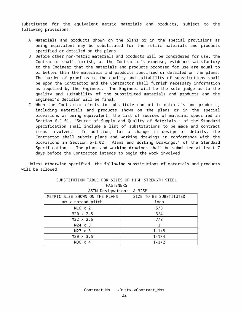
Minor concrete shall contain not less than 325 kg of cementitious material per cubic meter unless otherwise specified in these specifications or the special provisions.
Unless otherwise designated on the plans or specified in these specifications or the special provisions, the amount of cementitious material used per cubic meter of concrete in structures or portions of structures shall conform to the following:
UseCementitious Material Content
(kg/m3)Concrete which is designated by compressive strength:
Deck slabs and slab spans of bridgesRoof sections of exposed top box culvertsOther portions of structures
400 min., 475 max.400 min., 475 max.350 min., 475 max.
Concrete not designated by compressive strength:Deck slabs and slab spans of bridgesRoof sections of exposed top box culvertsPrestressed membersSeal coursesOther portions of structures
400 min.400 min.400 min.400 min.350 min.
Concrete for precast members 350 min., 550 max.
Whenever the 28-day compressive strength shown on the plans is greater than 25 MPa, the concrete shall be considered to be designated by compressive strength. If the plans show a 28-day compressive strength which is 31 MPa or greater, an additional 7 days will be allowed to obtain the specified strength. The 28-day compressive strengths shown on the plans which are 25 MPa or less are shown for design information only and are not to be considered a requirement for acceptance of the concrete.
Concrete designated by compressive strength shall be proportioned such that the concrete will conform to the strength shown on the plans or specified in the special provisions.
The Contractor shall determine the mix proportions for all concrete except pavement concrete. The Engineer will determine the mix proportions for pavement concrete.
Before using concrete for which the mix proportions have been determined by the Contractor, or in advance of revising those mix proportions, the Contractor shall submit in writing to the Engineer a copy of the mix design.
Compliance with cementitious material content requirements will be verified in conformance with procedures described in California Test 518 for cement content. For testing purposes, mineral admixture shall be considered to be cement. Batch proportions shall be adjusted as necessary to produce concrete having the specified cementitious material content.
If any concrete used in the work has a cementitious material content, consisting of cement, mineral admixture, or cement plus mineral admixture, which is less than the minimum required for the work, the concrete shall be removed. However, if the Engineer determines that the concrete is structurally adequate, the concrete may remain in place and the Contractor shall pay to the State $0.55 for each kilogram of cement, mineral admixture, or cement plus mineral admixture which is less than the minimum required for the work. The Department may deduct the amount from moneys due, or that may become due, the Contractor under the contract. The deductions will not be made unless the difference between the contents required and those actually provided exceeds the batching tolerances permitted by Section 90-5, "Proportioning." No deductions for cementitious material content will be made based on the results of California Test 518.
The requirements of the preceding paragraph shall not apply to minor concrete or commercial quality concrete. Concrete for which the mix proportions are determined either by the Contractor or the Engineer shall conform to the
requirements of this Section 90.
The first paragraph in Section 90-2.01, "Portland Cement," of the Standard Specifications is amended to read:
90-2.01 PORTLAND CEMENT Unless otherwise specified, portland cement shall be either "Type IP (MS) Modified" cement or "Type II Modified"
portland cement. "Type IP (MS) Modified" cement shall conform to the specifications for Type IP (MS) cement in ASTM
Designation: C 595, and shall be comprised of an intimate mixture of Type II cement and not more than 25 percent of a mineral admixture. The type and minimum amount of mineral admixture used in the manufacture of "Type IP (MS) Modified" cement shall be in conformance with the provisions in Section 90-4.08, "Required Use of Mineral Admixtures."
"Type II Modified" portland cement shall conform to the requirements for Type II portland cement in ASTM Designation: C 150.
Contract No. «Dist»-«Contract_No»26
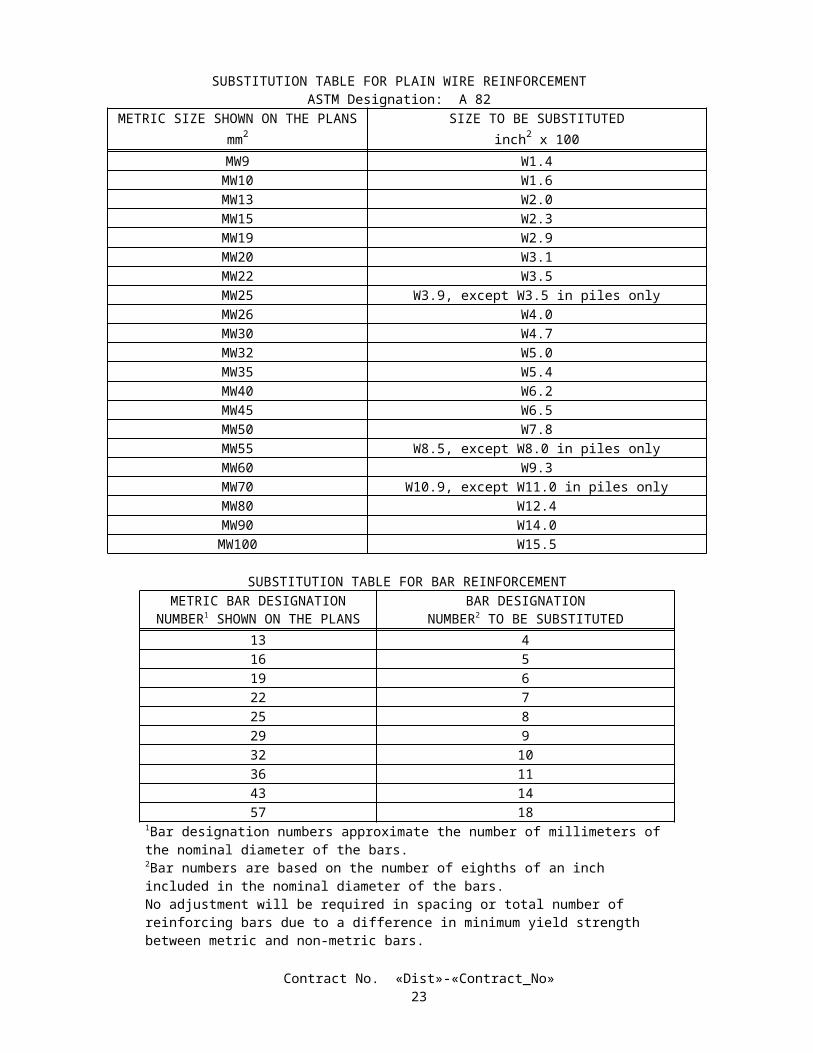
In addition, "Type IP (MS) Modified" cement and "Type II Modified" portland cement shall conform to the following requirements:
A. The cement shall not contain more than 0.60 percent by mass of alkalies, calculated as the percentage of Na2O plus 0.658 times the percentage of K2O, when determined by either direct intensity flame photometry or by the atomic absorption method. The instrument and procedure used shall be qualified as to precision and accuracy in conformance with the requirements in ASTM Designation: C 114.
B. The autoclave expansion shall not exceed 0.50 percent.C. Mortar, containing the cement to be used and Ottawa sand, when tested in conformance with California Test 527,
shall not expand in water more than 0.010 percent and shall not contract in air more than 0.048 percent except that when cement is to be used for precast prestressed concrete piling, precast prestressed concrete members or steam cured concrete products, the mortar shall not contract in air more than 0.053 percent.
The second paragraph in Section 90-2.01, "Portland Cement," of the Standard Specifications is amended to read:
Type III and Type V portland cements shall conform to the requirements in ASTM Designation: C 150, and the additional requirements listed above for Type II Modified portland cement, except that when tested in conformance with California Test 527, mortar containing Type III portland cement shall not contract in air more than 0.075 percent.
The third paragraph in Section 90-2.01, "Portland Cement," of the Standard Specifications is deleted.The twelfth paragraph in Section 90-2.02, "Aggregates," of the Standard Specifications is deleted.The first paragraph in Section 90-2.03, "Water," of the Standard Specifications is amended to read:
90-2.03 WATER In conventionally reinforced concrete work, the water for curing, for washing aggregates, and for mixing shall be
free from oil and shall not contain more than 1,000 parts per million of chlorides as Cl, nor more than 1,300 parts per million of sulfates as SO4. In prestressed concrete work, the water for curing, for washing aggregates, and for mixing shall be free from oil and shall not contain more than 650 parts per million of chlorides as Cl, nor more than 1,300 parts per million of sulfates as SO4. In no case shall the water contain an amount of impurities that will cause either: 1) a change in the setting time of cement of more than 25 percent when tested in conformance with the requirements in ASTM Designation: C 191 or ASTM Designation: C 266 or 2) a reduction in the compressive strength of mortar at 14 days of more than 5 percent, when tested in conformance with the requirements in ASTM Designation: C 109, when compared to the results obtained with distilled water or deionized water, tested in conformance with the requirements in ASTM Designation: C 109.
The following section is added to Section 90-2, "Materials," of the Standard Specifications:
90-2.04 ADMIXTURE MATERIALS Admixture materials shall conform to the requirements in the following ASTM Designations:
A. Chemical Admixtures—ASTM Designation: C 494.B. Air-entraining Admixtures—ASTM Designation: C 260.C. Calcium Chloride—ASTM Designation: D 98.D. Mineral Admixtures—Coal fly ash, raw or calcined natural pozzolan as specified in ASTM Designation: C618.
Silica fume conforming to the requirements in ASTM Designation: C1240, with reduction of mortar expansion of 80 percent, minimum, using the cement from the proposed mix design.
Mineral admixtures shall be used in conformance with the provisions in Section 90-4.08, "Required Use of Mineral Admixtures."
The first paragraph in Section 90-3.03, "Fine Aggregate Grading," is amended to read:
Fine aggregate shall be graded within the following limits:
Contract No. «Dist»-«Contract_No»27
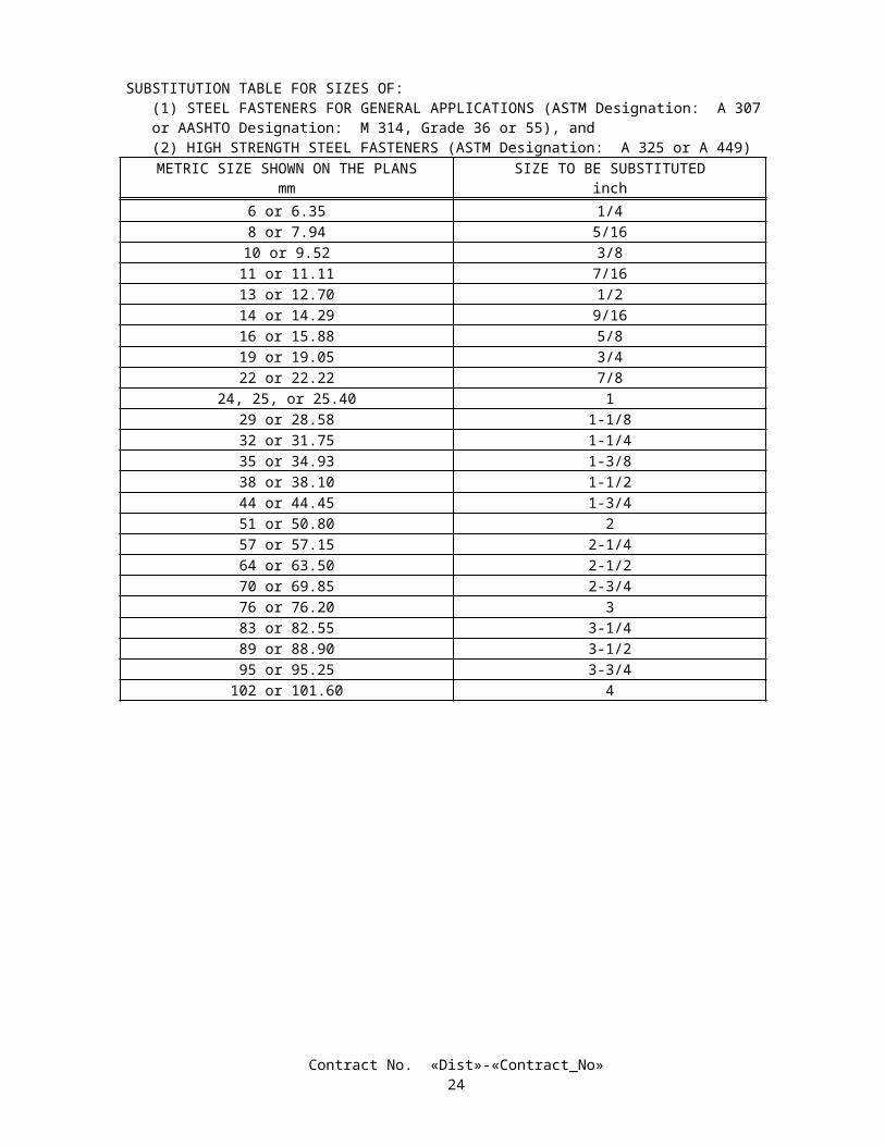
Percentage PassingSieve Sizes Operating Range Contract Compliance
9.5-mm 100 1004.75-mm 95-100 93-1002.36-mm 65-95 61-991.18-mm X ± 10 X ± 13600-µm X ± 9 X ± 12300-µm X ± 6 X ± 9150-µm 2-12 1-1575-µm 0-8 0-10
Section 90-4.02, "Materials," of the Standard Specifications is amended to read:
90-4.02 MATERIALS Admixture materials shall conform to the provisions in Section 90–2.04, "Admixture Materials."
Section 90-4.05, "Optional Use of Chemical Admixtures," of the Standard Specifications is amended to read:
90-4.05 OPTIONAL USE OF CHEMICAL ADMIXTURES The Contractor will be permitted to use Type A or F, water-reducing; Type B, retarding; or Type D or G, water-
reducing and retarding admixtures as described in ASTM Designation: C 494 to conserve cementitious material or to facilitate concrete construction application subject to the following conditions:
A. When a water-reducing admixture or a water-reducing and retarding admixture is used, the cementitious material content specified or ordered may be reduced by a maximum of 5 percent by mass except that the resultant cementitious material content shall be not less than 300 kilograms per cubic meter.
B. When a reduction in cementitious material content is made, the dosage of admixture used shall be the dosage used in determining approval of the admixture.
Section 90-4.07, "Optional Use of Air-entraining Admixtures," of the Standard Specifications is amended to read:
90-4.07 OPTIONAL USE OF AIR-ENTRAINING ADMIXTURES When air-entrainment has not been specified or ordered by the Engineer, the Contractor will be permitted to use an
air-entraining admixture to facilitate the use of any construction procedure or equipment provided that the average air content, as determined by California Test 504, of 3 successive tests does not exceed 4 percent and no single test value exceeds 5.5 percent. If the Contractor elects to use an air-entraining admixture in concrete for pavement, the Contractor shall so indicate at the time the Contractor designates the source of aggregate as provided in Section 40-1.015, "Cement Content."
Section 90-4.08, "Required Use of Mineral Admixtures," of the Standard Specifications is amended to read:
90-4.08 REQUIRED USE OF MINERAL ADMIXTURES Unless otherwise specified, mineral admixture shall be combined with cement to make cementitious material for use
in portland cement concrete. The calcium oxide content of mineral admixtures shall not exceed 10 percent and the available alkali, as sodium
oxide equivalent, shall not exceed 1.5 percent when determined in conformance with the requirements in ASTM Designation: C618.
The amounts of cement and mineral admixture used in cementitious material for portland cement concrete shall be sufficient to satisfy the minimum cementitious material content requirements specified in Section 90-1.01, "Description," or Section 90-4.05, "Optional Use of Chemical Admixtures," and shall conform to the following:
A. The minimum amount of cement shall not be less than 75 percent by mass of the specified minimum cementitious material content.
B. The minimum amount of mineral admixture to be combined with cement shall be determined using one of the following criteria:
1. When the calcium oxide content of a mineral admixture, as determined in conformance with the requirements in ASTM Designation: C618 and the provisions in Section 90-2.04, "Admixture Materials," is equal to or less than
Contract No. «Dist»-«Contract_No»28
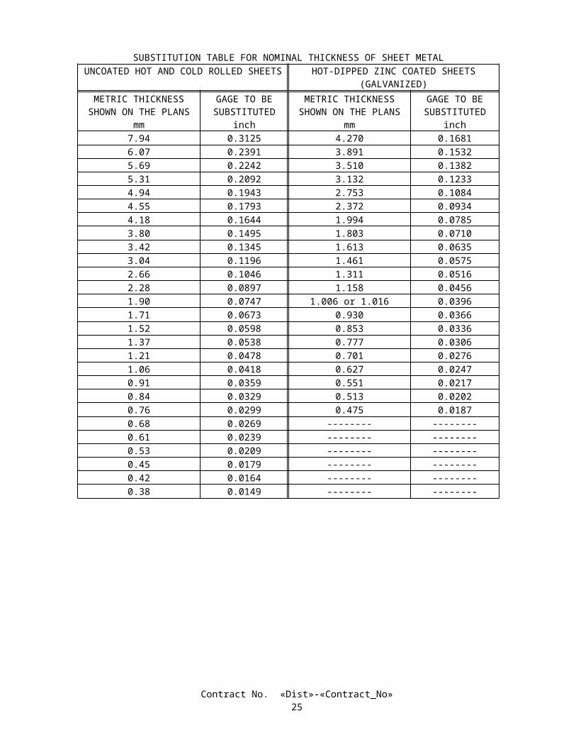
2 percent by mass, the amount of mineral admixture shall not be less than 15 percent by mass of the total amount of cementitious material to be used in the mix.
2. When the calcium oxide content of a mineral admixture, as determined in conformance with the requirements in ASTM Designation: C618 and the provisions in Section 90-2.04, "Admixture Materials," is greater than 2 percent, the amount of mineral admixture shall not be less than 25 percent by mass of the total amount of cementitious material to be used in the mix.
3. When a mineral admixture is used, which conforms to the provisions for silica fume in Section 90-2.04, "Admixture Materials," the amount of mineral admixture shall not be less than 10 percent by mass of the total amount of cementitious material to be used in the mix.
C. If more than the required amount of cementitious material is used, the additional cementitious material in the mix may be either cement, a mineral admixture conforming to the provisions in Section 90-2.04, "Admixture Materials," or a combination of both; however, the maximum total amount of mineral admixture shall not exceed 35 percent by mass of the total amount of cementitious material to be used in the mix. Where Section 90-1.01, "Description," specifies a maximum cementitious content in kilograms per cubic meter, the total mass of cement and mineral admixture per cubic meter shall not exceed the specified maximum cementitious material content.
Section 90-4.09, "Optional Use of Mineral Admixtures," of the Standard Specifications is deleted.Section 90-4.11, "Storage, Proportioning, and Dispensing of Mineral Admixtures," of the Standard Specifications is
amended to read:
90-4.11 STORAGE, PROPORTIONING, AND DISPENSING OF MINERAL ADMIXTURES Mineral admixtures shall be protected from exposure to moisture until used. Sacked material shall be piled to permit
access for tally, inspection, and identification for each shipment. Adequate facilities shall be provided to assure that mineral admixtures meeting the specified requirements are kept
separate from other mineral admixtures in order to prevent any but the specified mineral admixtures from entering the work. Safe and suitable facilities for sampling mineral admixtures shall be provided at the weigh hopper or in the feed line immediately in advance of the hopper.
Mineral admixtures shall be incorporated into concrete using equipment conforming to the requirements for cement weigh hoppers, and charging and discharging mechanisms in ASTM Designation: C 94, in Section 90-5.03, "Proportioning," and in this Section 90-4.11.
When interlocks are required for cement and mineral admixture charging mechanisms by Section 90-5.03A, "Proportioning for Pavement," and cement and mineral admixtures are weighed cumulatively, their charging mechanisms shall be interlocked to prevent the introduction of mineral admixture until the mass of cement in the cement weigh hopper is within the tolerances specified in Section 90-5.02, "Proportioning Devices."
Mineral admixture used in concrete for exposed surfaces of like elements of a structure shall be from the same source and of the same percentage.
Section 90-5.02, "Proportioning Devices," of the Standard Specifications is amended to read:
90-5.02 PROPORTIONING DEVICES Weighing, measuring or metering devices used for proportioning materials shall conform to the provisions in
Section 9-1.01, "Measurement of Quantities," and this Section 90-5.02. In addition, automatic weighing systems used shall comply with the provisions for automatic proportioning devices in Section 90-5.03A, "Proportioning for Pavement." These automatic devices shall be automatic to the extent that the only manual operation required for proportioning the aggregates, cement, and mineral admixture for one batch of concrete is a single operation of a switch or starter.
Proportioning devices shall be tested at the expense of the Contractor as frequently as the Engineer may deem necessary to insure their accuracy.
Weighing equipment shall be insulated against vibration or movement of other operating equipment in the plant. When the plant is in operation, the mass of each batch of material shall not vary from the mass designated by the Engineer by more than the tolerances specified herein.
Equipment for cumulative weighing of aggregate shall have a zero tolerance of ±0.5 percent of the designated total batch mass of the aggregate. For systems with individual weigh hoppers for the various sizes of aggregate, the zero tolerance shall be ±0.5 percent of the individual batch mass designated for each size of aggregate. Equipment for cumulative weighing of cement and mineral admixtures shall have a zero tolerance of ±0.5 percent of the designated total batch mass of the cement and mineral admixture. Equipment for weighing cement or mineral admixture separately shall have a zero tolerance of ±0.5 percent of their designated individual batch masses. Equipment for measuring water shall have a zero tolerance of ±0.5 percent of its designated mass or volume.
Contract No. «Dist»-«Contract_No»29
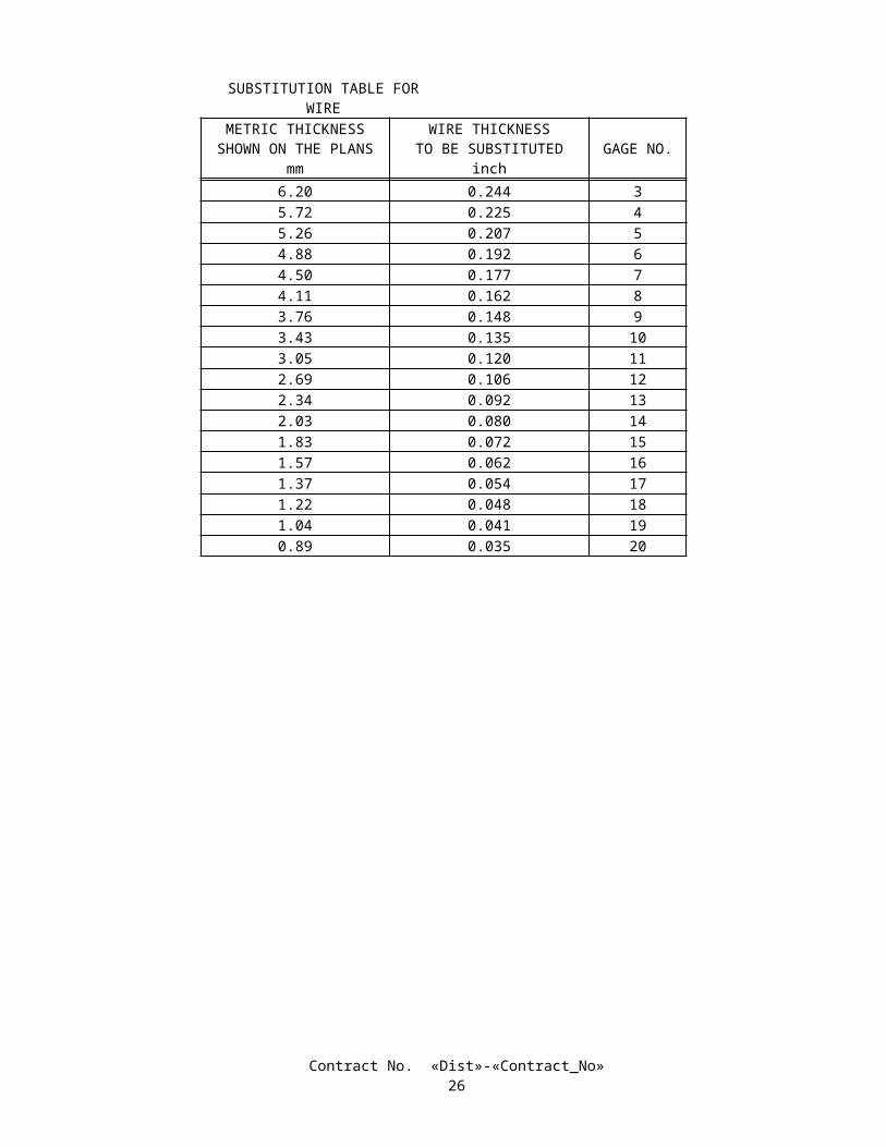
The mass indicated for a batch of material shall not vary from the preselected scale setting by more than the following:
A. Aggregate weighed cumulatively shall be within 1.0 percent of the designated total batch mass of the aggregate. Aggregates weighed individually shall be within 1.5 percent of their respective designated batch masses.
B. Cement shall be within 1.0 percent of its designated batch mass. When weighed individually, mineral admixture shall be within 1.0 percent of its designated batch mass. When mineral admixture and cement are permitted to be weighed cumulatively, cement shall be weighed first to within 1.0 percent of its designated batch mass, and the total for cement and mineral admixture shall be within 1.0 percent of the sum of their designated batch masses.
C. Water shall be within 1.5 percent of its designated mass or volume.
Each scale graduation shall be approximately 0.001 of the total capacity of the scale. The capacity of scales for weighing cement, mineral admixture, or cement plus mineral admixture and aggregates shall not exceed that of commercially available scales having single graduations indicating a mass not exceeding the maximum permissible mass variation above, except that no scale shall be required having a capacity of less than 500 kg, with 0.5 kg graduations.
Section 90-5.03, "Proportioning," excluding Section 90-5.03A, "Proportioning for Pavement," of the Standard Specifications is amended to read:
90-5.03 PROPORTIONING Proportioning shall consist of dividing the aggregates into the specified sizes, each stored in a separate bin, and
combining them with cement, mineral admixture, and water as provided in these specifications. Aggregates shall be proportioned by mass.
At the time of batching, aggregates shall have been dried or drained sufficiently to result in a stable moisture content such that no visible separation of water from aggregate will take place during transportation from the proportioning plant to the point of mixing. In no event shall the free moisture content of the fine aggregate at the time of batching exceed 8 percent of its saturated, surface-dry mass.
Should separate supplies of aggregate material of the same size group, but of different moisture content or specific gravity or surface characteristics affecting workability, be available at the proportioning plant, withdrawals shall be made from one supply exclusively and the materials therein completely exhausted before starting upon another.
Bulk "Type IP (MS) Modified" cement that conforms to the provisions in Section 90-2.01, "Portland Cement," shall be weighed in an individual hopper and shall be kept separate from the aggregates until the ingredients are released for discharge into the mixer.
Bulk cement to be blended with mineral admixture for use in portland cement concrete for pavement and structures may be weighed in separate, individual weigh hoppers or may be weighed in the same weigh hopper with mineral admixture and shall be kept separate from the aggregates until the ingredients are released for discharge into the mixer. If the cement and mineral admixture are weighed cumulatively, the cement shall be weighed first.
When cement and mineral admixtures are weighed in separate weigh hoppers, the weigh systems for the proportioning of the aggregate, the cement, and the mineral admixture shall be individual and distinct from other weigh systems. Each weigh system shall be equipped with a hopper, a lever system, and an indicator to constitute an individual and independent material weighing device. The cement and the mineral admixture shall be discharged into the mixer simultaneously with the aggregate.
The scale and weigh hopper for bulk weighing cement, mineral admixture, and cement plus mineral admixture shall be separate and distinct from the aggregate weighing equipment.
When the source of an aggregate is changed for concrete structures, the Contractor shall adjust the mix proportions and submit in writing to the Engineer a copy of the mix design before using such aggregates. When the source of an aggregate is changed for other concrete, the Engineer shall be allowed sufficient time to adjust the mix and such aggregates shall not be used until necessary adjustments are made.
For batches with a volume of one cubic meter or more, the batching equipment shall conform to one of the following combinations:
A. Separate boxes and separate scale and indicator for weighing each size of aggregate.B. Single box and scale indicator for all aggregates.C. Single box or separate boxes and automatic weighing mechanism for all aggregates.
In order to check the accuracy of batch masses, the gross mass and tare mass of batch trucks, truck mixers, truck agitators, and non-agitating hauling equipment shall be determined when ordered by the Engineer. The equipment shall be weighed at the Contractor's expense on scales designated by the Engineer.
Contract No. «Dist»-«Contract_No»30
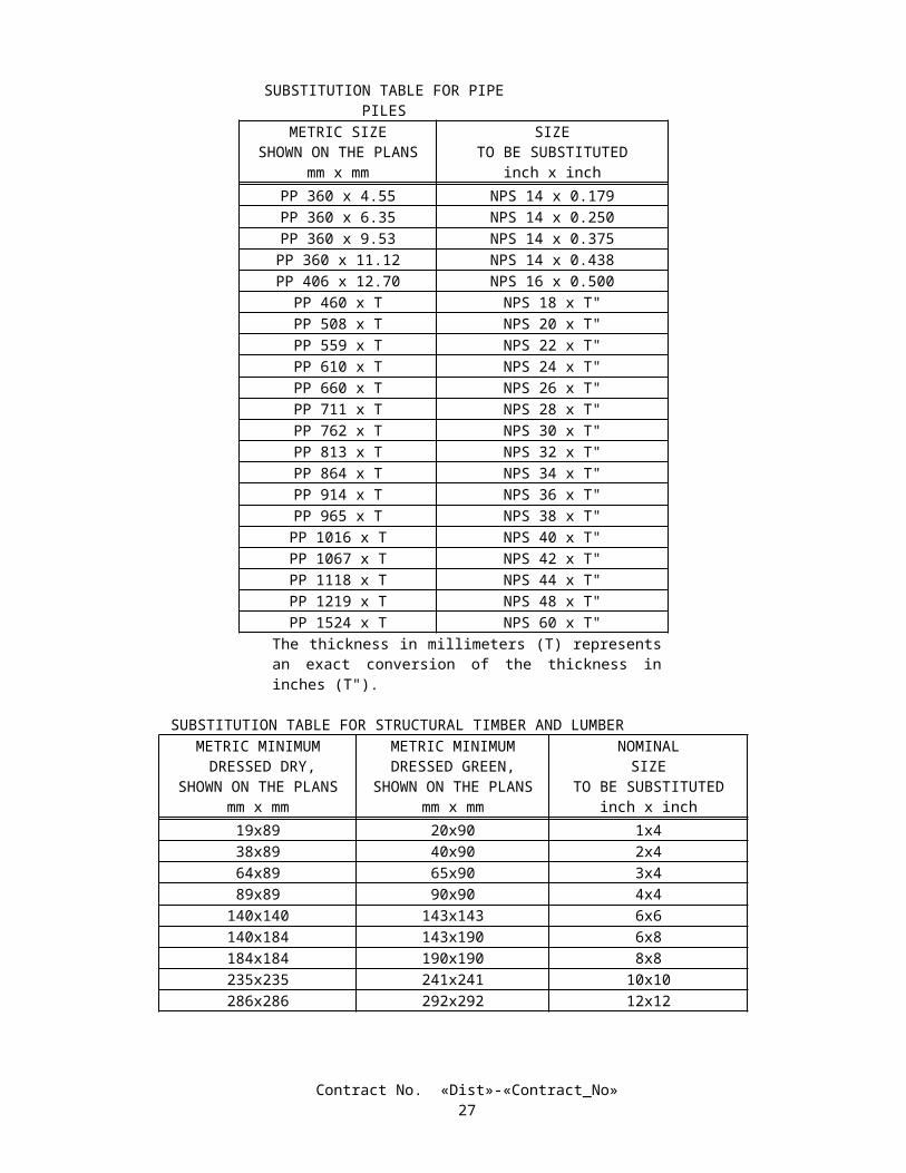
Section 90-10.02A, "Portland Cement," of the Standard Specifications is renamed "Cementitious Material" and is amended to read:
90-10.02A CEMENTITIOUS MATERIAL Cementitious material shall conform to the provisions in Section 90-1.01, "Description." Compressive strength
requirements consist of a minimum strength which must be attained before various loads or stresses are applied to the concrete and, for concrete designated by strength, a minimum strength at the age of 28 days or at the age otherwise allowed in Section 90-1.01, "Description." The various strengths required are specified in these specifications or are shown on the plans.
The fifth paragraph in Section 90-10.02B, "Aggregate," of the Standard Specifications is deleted.Section 90-10.03, "Production," of the Standard Specifications is amended to read:
90-10.03 PRODUCTION Cementitious material, water, aggregate, and admixtures shall be stored, proportioned, mixed, transported, and
discharged in conformance with recognized standards of good practice, which will result in concrete that is thoroughly and uniformly mixed, which is suitable for the use intended, and which conforms to provisions specified herein. Recognized standards of good practice are outlined in various industry publications such as those issued by American Concrete Institute, AASHTO, or California Department of Transportation.
The cementitious material content of minor concrete shall conform to the provisions in Section 90-1.01, "Description."
The amount of water used shall result in a consistency of concrete conforming to the provisions in Section 90 -6.06, "Amount of Water and Penetration." Additional mixing water shall not be incorporated into the concrete during hauling or after arrival at the delivery point, unless authorized by the Engineer.
Discharge of ready-mixed concrete from the transporting vehicle shall be made while the concrete is still plastic and before stiffening occurs. An elapsed time of 1.5 hours (one hour in non-agitating hauling equipment), or more than 250 revolutions of the drum or blades, after the introduction of the cementitious material to the aggregates, or a temperature of concrete of more than 32°C will be considered as conditions contributing to the quick stiffening of concrete. The Contractor shall take whatever action is necessary to eliminate quick stiffening, except that the addition of water will not be permitted.
The required mixing time in stationary mixers shall be not less than 50 seconds or more than 5 minutes. The minimum required revolutions at mixing speed for transit-mixed concrete shall be not less than that
recommended by the mixer manufacturer, and shall be increased, if necessary, to produce thoroughly and uniformly mixed concrete.
Each load of ready-mixed concrete shall be accompanied by a weight certificate which shall be delivered to the Engineer at the discharge location of the concrete, unless otherwise directed by the Engineer. The weight certificate shall be clearly marked with the date and time of day when the load left the batching plant and, if hauled in truck mixers or agitators, the time the mixing cycle started.
A Certificate of Compliance conforming to the provisions in Section 6–1.07, "Certificates of Compliance," shall be furnished to the Engineer, prior to placing minor concrete from a source not previously used on the contract, stating that minor concrete to be furnished meets contract requirements, including minimum cementitious material content specified.
SECTION 8-3. (BLANK)SECTION 9. (BLANK)
SECTION 10. CONSTRUCTION DETAILSSECTION 10-1. GENERAL
10-1.00 CONSTRUCTION PROJECT INFORMATION SIGNSBefore any major physical construction work readily visible to highway users is started on this contract, the Contractor
shall furnish and erect 2 Type 2 Construction Project Information signs at the locations designated by the Engineer.The signs and overlays shall be of a type and material consistent with the estimated time of completion of the project and
shall conform to the details shown on the plans.The sign letters, border and the Department's construction logos shall conform to the colors (non-reflective) and details
shown on the plans, and shall be on a white background (non-reflective). The colors blue and orange shall conform to PR Color Number 3 and Number 6, respectively, as specified in the Federal Highway Administration's Color Tolerance Chart.
The sign message to be used for fund types shall consist of the following, in the order shown:
Contract No. «Dist»-«Contract_No»31
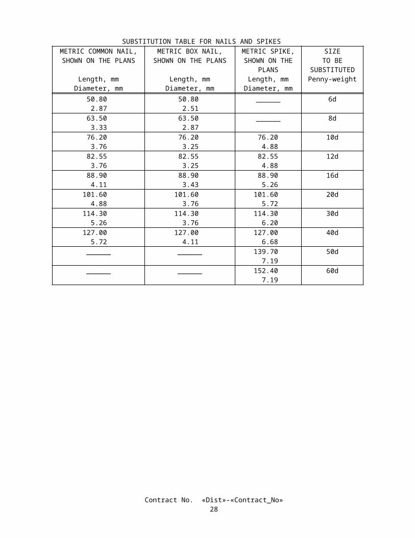
FEDERAL HIGHWAY TRUST FUNDSSTATE HIGHWAY FUNDS
The sign message to be used for type of work shall consist of the following:
ROADSIDE WORK
The sign message to be used for the Year of Completion of Project Construction will be furnished by the Engineer. The Contractor shall furnish and install the "Year" sign overlay within 10 working days of notification of the year date to be used.
The letter sizes to be used shall be as shown on the plans. The information shown on the signs shall be limited to that shown on the plans.
The signs shall be kept clean and in good repair by the Contractor.Upon completion of the work, the signs shall be removed and disposed of outside the highway right of way in
conformance with the provisions in Section 7-1.13 of the Standard Specifications.Full compensation for furnishing, erecting, maintaining, and removing and disposing of the construction project
information signs shall be considered as included in the contract lump sum price paid for construction area signs and no additional compensation will be allowed therefor.
10-1.01 ORDER OF WORKOrder of work shall conform to the provisions in Section 5-1.05, "Order of Work," of the Standard Specifications and
these special provisions.Within 30 days after the contract has been approved, the Contractor shall furnish the Engineer a statement from the
vendor that the order for the plants required for this contract, including inspection plants, has been received and accepted by the vendor. The statement from the vendor shall include the names, sizes, and quantities of plants ordered and the anticipated date of delivery.
The Contractor shall place orders for replacement plants with the vendor at the appropriate time so that the roots of the replacement plants are not in a root-bound condition.
Attention is directed to Section 9-1.06, "Partial Payments," of the Standard Specifications. For progress payment purposes, the Department will retain 50 percent of the estimated value of highway planting work done until a statement from the vendor that the order for the plants required for this contract has been submitted to the Engineer.
Attention is directed to "Irrigation Systems Functional Test" of these special provisions, regarding restrictions for planting operations.
Attention is directed to "Locate Existing Crossovers and Conduits" of these special provisions regarding locating existing irrigation water line crossovers and conduits shown on the plans to be incorporated in the new work. Existing irrigation water line crossovers and conduits shall be located prior to performing work on the irrigation system.
Unless otherwise shown on the plans or specified in these special provisions, conduits to be installed by the directional boring for water line crossovers and sprinkler control crossovers shall be installed prior to the installation of other pipe supply lines.
Attention is directed to "Existing Highway Irrigation Facilities" of these special provisions regarding the checking of existing irrigation facilities that are to remain in place, prior to the start of any irrigation work.
Attention is directed to Section 20-5.027B, "Wiring Plans and Diagrams," of the Standard Specifications regarding submittal of working drawings.
Attention is directed to "Irrigation Controller Enclosure Cabinet" of these special provisions regarding preinstalling irrigation components in the irrigation controller enclosure cabinet prior to field installation.
10-1.02 MATERIAL CONTAINING AERIALLY DEPOSITED LEADThis work shall consist of handling soil contaminated by aerially deposited lead in conformance with the Standard
Specifications and these special provisions.Aerially deposited lead is typically found within the top 0.6-m of material in unpaved areas within the highway right of
way. Levels of lead found near the project limits range from less than 8.7 to 1,590 mg/kg total lead, as analyzed by EPA Test Method 6010 or EPA Test Method 7000 series.
After the Contractor has completed handling materials containing aerially deposited lead, in conformance with the plans, Standard Specifications, and these special provisions, the Contractor shall have no responsibility for such materials in place and shall not be obligated for further cleanup, removal, or remedial actions for such materials.
Handling material containing aerially deposited lead shall be in conformance with all the rules and regulations of agencies including, but not limited to, the following:
California Division of Occupational Safety and Health Administration (Cal-OSHA)
Contract No. «Dist»-«Contract_No»32
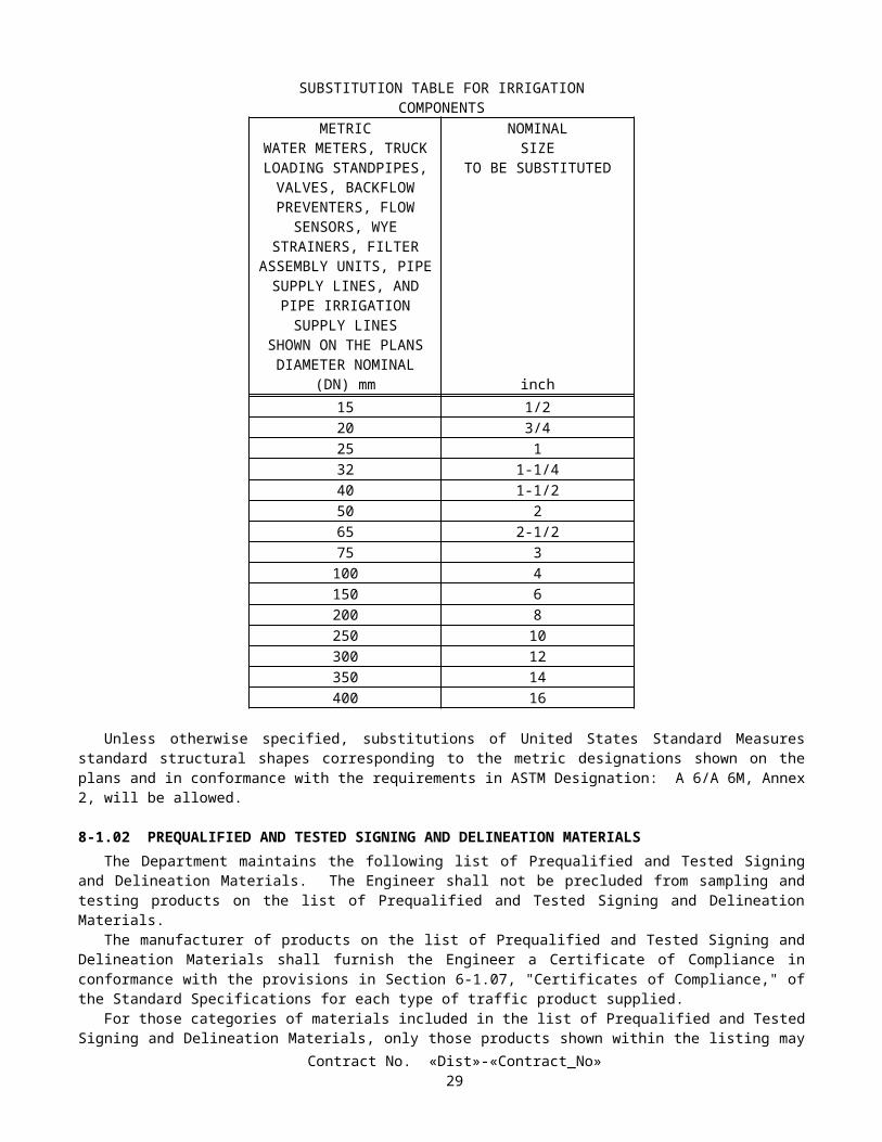
California Regional Water Quality Control Board, Region 9.
The Contractor shall procure all permits and licenses, pay all charges and fees, except as otherwise provided in these special provisions, and give all notices necessary and incidental to the due and lawful prosecution of the work.
Full compensation for conforming to the requirements of this section, (except for the Lead Compliance Plan) shall be considered as included in the prices paid for the various contract items of work involved and no additional compensation will be allowed therefor.
HEALTH AND SAFETYThe Contractor shall prepare a project specific Lead Compliance Plan to prevent or minimize worker exposure to lead
contamination in soil. Attention is directed to Title 8, California Code of Regulations, Section 1532.1, “Lead,” for specific Cal-OSHA requirements when working with lead.
The Lead Compliance Plan shall contain all of the elements listed in Title 8, California Code of Regulations, Section 1532.1(e)(2)(B). Before submission to the Engineer, the Lead Compliance Plan shall be approved by an Industrial Hygienist certified in Comprehensive Practice by the American Board of Industrial Hygiene. The Plan shall be submitted to the Engineer at least 7 days prior to beginning work in areas containing aerially deposited lead.
Prior to performing work in areas containing lead, personnel who have no prior training, including State personnel, shall complete a safety training program provided by the Contractor, that meets the requirements of Title 8, California Code of Regulations, Section 1532.1, "Lead," and the Contractor’s Lead Compliance Program.
Personal protective equipment, training, washing facilities, and medical surveillance required by the Contractor's Lead Compliance Plan shall be supplied to State personnel by the Contractor. The number of State personnel will be 5.
Lead Compliance Plan will be paid as a lump sum.The contract lump sum price paid for Lead Compliance Plan shall include full compensation for furnishing all labor,
materials, tools, equipment, and incidentals and for doing all the work involved in preparing the Lead Compliance Plan, including paying the Certified Industrial Hygienist, and for providing personal protective equipment, training and medical surveillance, as specified in the Standard Specifications and these special provisions, and as directed by the Engineer.
SOIL HANDLINGHandling of soils containing aerially deposited lead shall result in no visible dust migration. The Contractor shall have a
dust palliative available at all times while handling soils in work areas containing aerially deposited lead.The Contractor shall separate soil from vegetation and the soils shall remain on site.Surplus soil excavated from areas containing aerially deposited lead shall remain in the area of soil disturbance. The
surplus soil shall not be disposed of outside the highway right of way.Full compensation for handling soil contaminated with aerially deposited lead, except as otherwise provided, shall be
considered as included in the prices paid for the various contract items of work involved and no additional compensation will be allowed therefor.
10-1.03 WATER POLLUTION CONTROLWater pollution control work shall conform to the provisions in Section 7-1.01G, "Water Pollution," of the Standard
Specifications and these special provisions.Water pollution control work shall conform to the requirements in the Construction Contractor's Guide and
Specifications of the Caltrans Storm Water Quality Handbooks, dated April 1997, and addenda thereto issued up to and including the date of advertisement of the project, hereafter referred to as the "Handbook." Copies of the Handbook may be obtained from the Department of Transportation, Material Operations Branch, Publication Distribution Unit, 1900 Royal Oaks Drive, Sacramento, California 95815, Telephone: (916) 445-3520.
Copies of the Handbook are also available for review at Caltrans District Office, District Construction Liaison Office, 2829 Juan Street, San Diego, California 92110, Telephone (619) 688-6635.
The Contractor shall know and fully comply with the applicable provisions of the Handbook and Federal, State, and local regulations that govern the Contractor's operations and storm water discharges from both the project site and areas of disturbance outside the project limits during construction.
Unless arrangements for disturbance of areas outside the project limits are made by the Department and made part of the contract, it is expressly agreed that the Department assumes no responsibility whatsoever to the Contractor or property owner with respect to any arrangements made between the Contractor and property owner to allow disturbance of areas outside the project limits.
The Contractor shall be responsible for the costs and for liabilities imposed by law as a result of the Contractor's failure to comply with the requirements set forth in this section "Water Pollution Control" including, but not limited to, compliance with the applicable provisions of the Handbook and Federal, State, and local regulations. For the purposes of this paragraph,
Contract No. «Dist»-«Contract_No»33
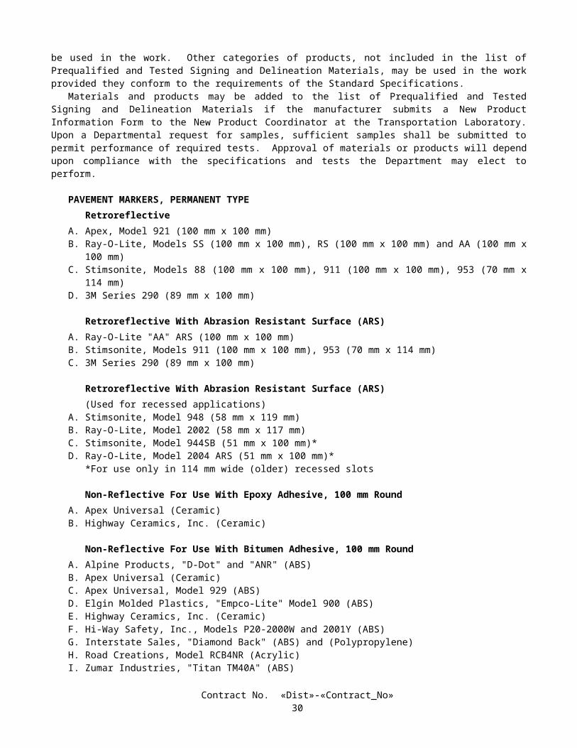
costs and liabilities include, but are not limited to, fines, penalties, and damages whether assessed against the State or the Contractor, including those levied under the Federal Clean Water Act and the State Porter Cologne Water Quality Act.
In addition to the remedies authorized by law, an amount of the money due the Contractor under the contract, as determined by the Department, may be retained by the State of California until disposition has been made of the costs and liabilities.
The retention of money due the Contractor shall be subject to the following:
A. The Department will give the Contractor 30 days notice of the Department's intention to retain funds from partial payments which may become due to the Contractor prior to acceptance of the contract. Retention of funds from payments made after acceptance of the contract may be made without prior notice to the Contractor.
B. No retention of additional amounts out of partial payments will be made if the amount to be retained does not exceed the amount being withheld from partial payments pursuant to Section 9-1.06, "Partial Payments," of the Standard Specifications.
C. If the Department has retained funds and it is subsequently determined that the State is not subject to the costs and liabilities in connection with the matter for which the retention was made, the Department shall be liable for interest on the amount retained at the legal rate of interest for the period of the retention.
Conformance with the provisions in this section "Water Pollution Control" shall not relieve the Contractor from the Contractor's responsibilities as provided in Section 7, "Legal Relations and Responsibilities," of the Standard Specifications.
WATER POLLUTION CONTROL PROGRAM PREPARATION, APPROVAL AND UPDATESAs part of the water pollution control work, a Water Pollution Control Program, hereafter referred to as the "WPCP," is
required for this contract. The WPCP shall conform to the provisions in Section 7-1.01G, "Water Pollution," of the Standard Specifications, the requirements in the Handbook, and these special provisions.
No work having potential to cause water pollution, as determined by the Engineer, shall be performed until the WPCP has been approved by the Engineer.
Within 15 days after the approval of the contract, the Contractor shall submit 5 copies of the WPCP to the Engineer. The Engineer will have 7 days to review the WPCP. If revisions are required, as determined by the Engineer, the Contractor shall revise and resubmit the WPCP within 3 days of receipt of the Engineer's comments. The Engineer will have 3 days to review the revisions. Upon the Engineer's approval of the WPCP, 3 additional copies of the WPCP incorporating the required changes shall be submitted to the Engineer. Minor changes or clarifications to the initial submittal may be made and attached as amendments to the WPCP. In order to allow construction activities to proceed, the Engineer may conditionally approve the WPCP while minor revisions or amendments are being completed.
The WPCP shall identify pollution sources that may adversely affect the quality of storm water discharges associated with the project and shall identify water pollution control measures, hereafter referred to as control measures, to be constructed, implemented, and maintained in order to reduce to the extent feasible pollutants in storm water discharges from the construction site during construction under this contract.
The WPCP shall incorporate control measures in the following categories:
A. Soil stabilization practices;B. Sediment control practices;C. Sediment tracking control practices;D. Wind erosion control practices; andE. Nonstorm water management and waste management and disposal control practices.
Specific objectives and minimum requirements for each category of control measures are contained in the Handbook.The Contractor shall consider the objectives and minimum requirements presented in the Handbook for each of the
above categories. When minimum requirements are listed for any category, the Contractor shall incorporate into the WPCP and implement on the project, one or more of the listed minimum controls required in order to meet the pollution control objectives for the category. In addition, the Contractor shall consider other control measures presented in the Handbook and shall incorporate into the WPCP and implement on the project the control measures necessary to meet the objectives of the WPCP. The Contractor shall document the selection process in conformance with the procedure specified in the Handbook.
The following contract items of work, where shown on the project plans, shall be incorporated into the WPCP as critical temporary control measures: temporary fiber roll. The Contractor shall consider other control measures to supplement these critical temporary control measures when necessary to meet the pollution control objectives of the WPCP.
The WPCP shall include, but not be limited to, the following items as described in the Handbook:
A. Project description and Contractor's certification;B. Project information;
Contract No. «Dist»-«Contract_No»34
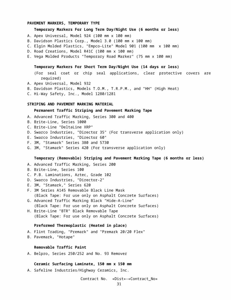
C. Pollution sources, control measures, and water pollution control drawings; andD. Amendments, if any.
The Contractor shall amend the WPCP, graphically and in narrative form, whenever there is a change in construction activities or operations which may affect the discharge of significant quantities of pollutants to surface waters, ground waters, municipal storm drain systems or when deemed necessary by the Engineer. The WPCP shall be amended if the WPCP has not achieved the objective of reducing pollutants in storm water discharges. Amendments shall show additional control measures or revised operations, including those in areas not shown in the initially approved WPCP, which are required on the project to control water pollution effectively. Amendments to the WPCP shall be submitted for review and approval by the Engineer in the same manner specified for the initially approved WPCP. Amendments shall be dated and attached to the on-site WPCP document.
The Contractor shall keep a copy of the WPCP, together with updates, revisions and amendments at the project site.
WPCP IMPLEMENTATIONUpon approval of the WPCP, the Contractor shall be responsible throughout the duration of the project for installing,
constructing, inspecting, and maintaining the control measures included in the WPCP and any amendments thereto and for removing and disposing of temporary control measures. Unless otherwise directed by the Engineer or specified in these special provisions, the Contractor's responsibility for WPCP implementation shall continue throughout any temporary suspension of work ordered in conformance with the provisions in Section 8-1.05, "Temporary Suspension of Work," of the Standard Specifications. Requirements for installation, construction, inspection, maintenance, removal, and disposal of control measures are specified in the Handbook and these special provisions.
Soil stabilization practices and sediment control measures, including minimum requirements, shall be provided throughout the winter season, defined as between November 1 and March 30.
Implementation of soil stabilization practices and sediment control measures for soil-disturbed areas on the project site shall be completed, except as provided for below, not later than 20 days prior to the beginning of the winter season or upon start of applicable construction activities for projects which begin either during or within 20 days of the winter season.
Throughout the winter season, the active, soil-disturbed area of the project site shall be not more than 1.95 hectares. The Engineer may approve, on a case-by-case basis, expansions of the active, soil-disturbed area limit. The Contractor shall demonstrate the ability and preparedness to fully deploy soil stabilization practices and sediment control measures to protect soil-disturbed areas on the project site before the onset of precipitation. A quantity of soil stabilization and sediment control materials shall be maintained on site equal to 100 percent of that sufficient to protect unprotected, soil-disturbed areas on the project site. A detailed plan for the mobilization of sufficient labor and equipment shall be maintained to fully deploy control measures required to protect unprotected, soil-disturbed areas on the project site prior to the onset of precipitation. A current inventory of control measure materials and the detailed mobilization plan shall be included as part of the WPCP.
Throughout the winter season, soil-disturbed areas on the project site shall be considered to be nonactive whenever soil disturbing activities are expected to be discontinued for a period of 20 or more days and the areas are fully protected. Areas that will become nonactive either during the winter season or within 20 days thereof shall be fully protected with soil stabilization practices and sediment control measures within 10 days of the discontinuance of soil disturbing activities or prior to the onset of precipitation, whichever is first to occur.
Throughout the winter season, active soil-disturbed areas of the project site shall be fully protected at the end of each day with soil stabilization practices and sediment control measures unless fair weather is predicted through the following work day. The weather forecast shall be monitored by the Contractor on a daily basis. The National Weather Service forecast shall be used. An alternative weather forecast proposed by the Contractor may be used if approved by the Engineer. If precipitation is predicted prior to the end of the following work day, construction scheduling shall be modified, as required, and functioning control measures shall be deployed prior to the onset of the precipitation.
The Contractor shall implement, year-round and throughout the duration of the project, control measures included in the WPCP for sediment tracking, wind erosion, nonstorm water management, and waste management and disposal.
The Engineer may order the suspension of construction operations which create water pollution if the Contractor fails to conform to the provisions in this section "Water Pollution Control" as determined by the Engineer.
MAINTENANCETo ensure the proper implementation and functioning of control measures, the Contractor shall regularly inspect and
maintain the construction site for the control measures identified in the WPCP. The Contractor shall identify corrective actions and time needed to address any deficient measures or reinitiate any measures that have been discontinued.
The construction site inspection checklist provided in the Handbook shall be used to ensure that the necessary measures are being properly implemented, and to ensure that the control measures are functioning adequately. One copy of each site inspection record shall be submitted to the Engineer.
Contract No. «Dist»-«Contract_No»35
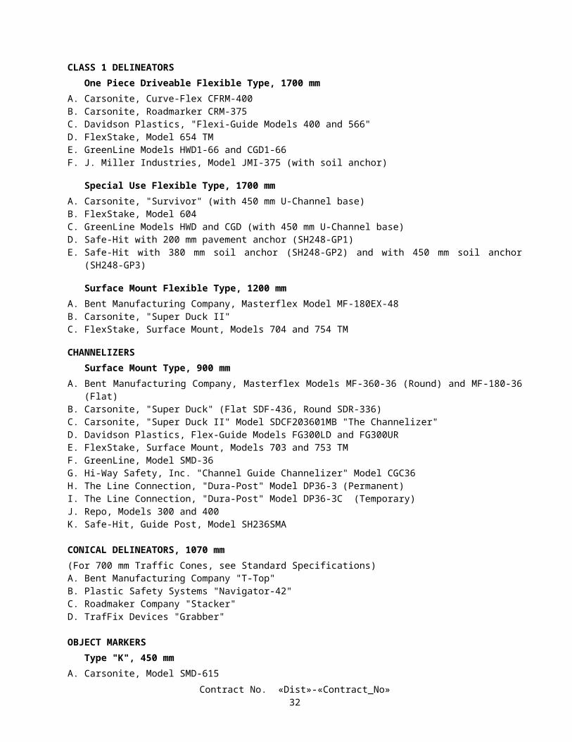
During the winter season, inspections of the construction site shall be conducted by the Contractor to identify deficient measures, as follows:
A. Prior to a forecast storm;B. After all precipitation which causes runoff capable of carrying sediment from the construction site;C. At 24-hour intervals during extended precipitation events; andD. Routinely, at a minimum of once every 2 weeks.
If the Contractor or the Engineer identifies a deficiency in the deployment or functioning of an identified control measure, the deficiency shall be corrected immediately. The deficiency may be corrected at a later date and time if requested by the Contractor and approved by the Engineer in writing, but not later than the onset of subsequent precipitation events. The correction of deficiencies shall be at no additional cost to the State.
WATER POLLUTION CONTROL TRAININGThe Contractor's management and supervisory personnel along with workers involved with the placement and
maintenance of storm water pollution prevention “Best Management Practices” shall be trained on general storm water pollution control requirements consistent with the "Caltrans Storm Water Quality Handbook, Construction Contractor's Guide and Specifications". The training is to be provided by the Contractor. The amount of training provided should be commensurate with the job performed by the employee.
PAYMENTFull compensation for conforming to the provisions in this section shall be considered as included in the prices paid for
the various contract items of work involved and no additional compensation will be allowed therefor.Those control measures which are shown on the plans and for which there is a contract item of work will be measured
and paid for as that contract item of work.The Engineer will retain an amount equal to 25 percent of the estimated value of the contract work performed during
estimate periods in which the Contractor fails to conform to the provisions in this section "Water Pollution Control" as determined by the Engineer.
Retentions for failure to conform to the provisions in this section "Water Pollution Control" shall be in addition to the other retentions provided for in the contract. The amounts retained for failure of the Contractor to conform to the provisions in this section will be released for payment on the next monthly estimate for partial payment following the date that a WPCP has been implemented and maintained and water pollution is adequately controlled, as determined by the Engineer.
10-1.04 TEMPORARY FIBER ROLLTemporary fiber rolls shall conform to the details shown on the plans, the provisions in Section 20 -3, "Erosion Control,"
of the Standard Specifications and these special provisions.Temporary fiber rolls shall be furnished, installed, maintained, and removed at the locations shown on the plans.Attention is directed to "Water Pollution Control" of these special provisions.
MATERIALSMaterials for temporary fiber rolls shall conform to the provisions in Section 20-2, "Materials," of the Standard
Specifications.Temporary fiber roll shall consist of a field rolled erosion control blanket rolled into tubes with a minimum diameter of
200 mm. The rolls shall be bound with a jute-type twine at the ends and at a minimum of every 1.8 m along the length of the roll. The roll shall weigh not less than 1.9 kg per linear meter.
Stakes shall be fir or pine and shall have a cross-sectional area of at least 360 mm2 and a minimum length of 600 mm.
INSTALLATIONTemporary fiber roll shall be installed as shown on the plans and in conformance with Detail Sheet 1 in Appendix C,
CD43(2) in the Construction Contractors Guide and Specifications of the Caltrans Storm Water Quality Handbooks and the manufacturer's recommendations.
Temporary fiber rolls shall be maintained to disperse concentrated water runoff and to reduce runoff velocities. When no longer required for the intended purpose, as determined by the Engineer, temporary fiber rolls shall be removed from the site of the work.
Contract No. «Dist»-«Contract_No»36
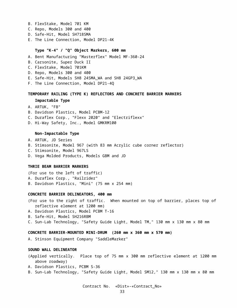
MEASUREMENT AND PAYMENTThe quantity of temporary fiber roll will be measured by the meter as determined from one end to the other end along the
surface of the roll.The contract price paid per meter for temporary fiber roll shall include full compensation for furnishing all labor,
materials, tools, equipment, and incidentals, and for doing all the work involved in installing temporary fiber rolls, complete in place, including maintenance and removal of materials, as shown on the plans, as specified in the Standard Specifications and these special provisions, and as directed by the Engineer.
Temporary fiber roll placed at locations other than as shown on the plans or where directed by the Engineer, in conformance with the Contractor's Water Pollution Control Program, will not be measured and will be paid for as specified in "Water Pollution Control" of these special provisions.
No adjustment of compensation will be made for any increase or decrease in the quantities of temporary fiber roll required, regardless of the reason for the increase or decrease. The provisions in Section 4-1.03B, "Increased or Decreased Quantities," of the Standard Specifications shall not apply to temporary fiber roll.
10-1.05 PRESERVATION OF PROPERTYAttention is directed to Section 7-1.11, "Preservation of Property," of the Standard Specifications and these special
provisions.Existing trees, shrubs and other plants, that are not to be removed as shown on the plans or specified in these special
provisions, and are injured or damaged by reason of the Contractor's operations, shall be replaced by the Contractor. The minimum size of tree replacement shall be 600 mm box and the minimum size of shrub replacement shall be No. 15 container. Replacement ground cover plants shall be from flats and shall be planted 300 mm on center. Replacement of Carpobrotus ground cover plants shall be from cuttings and shall be planted 300 mm on center. Replacement planting shall conform to the requirements in Section 20-4.07, "Replacement," of the Standard Specifications. The Contractor shall water replacement plants in conformance with the provisions in Section 20-4.06, "Watering," of the Standard Specifications.
Damaged or injured plants shall be removed and disposed of outside the highway right of way in conformance with the provisions in Section 7-l.13 of the Standard Specifications. At the option of the Contractor, removed trees and shrubs may be reduced to chips. The chipped material shall be spread within the highway right of way at locations designated by the Engineer.
Replacement planting of injured or damaged trees, shrubs, and other plants shall be completed prior to the start of the plant establishment period. Replacement planting shall conform to the provisions in Section 20-4.05, "Planting," of the Standard Specifications.
10-1.06 OBSTRUCTIONSAttention is directed to Section 8-1.10, "Utility and Non-Highway Facilities," and Section 15, "Existing Highway
Facilities," of the Standard Specifications and these special provisions.Attention is directed to the existence of certain underground facilities that may require special precautions be taken by
the Contractor to protect the health, safety and welfare of workers and of the public. Facilities requiring special precautions include, but are not limited to: conductors of petroleum products, oxygen, chlorine, and toxic or flammable gases; natural gas in pipelines greater than 150 mm in diameter or pipelines operating at pressures greater than 415 kPa (gage); underground electric supply system conductors or cables, with potential to ground of more than 300 V, either directly buried or in a duct or conduit which do not have concentric grounded or other effectively grounded metal shields or sheaths.
The Contractor shall notify the Engineer and the appropriate regional notification center for operators of subsurface installations at least 2 working days, but not more than 14 calendar days, prior to performing any excavation or other work close to any underground pipeline, conduit, duct, wire or other structure. Regional notification centers include, but are not limited to, the following:
Notification Center Telephone NumberUnderground Service Alert-Northern California (USA) 1-800-642-2444
1-800-227-2600Underground Service Alert-Southern California (USA) 1-800-422-4133
1-800-227-2600
The following utility facilities are shown on the plans and require special handling. This does not relieve the Contractor of his responsibility for other utility facilities on the project.
Utility Location Note200 mm Naval Fuel Line Station 39+55 B
Contract No. «Dist»-«Contract_No»37
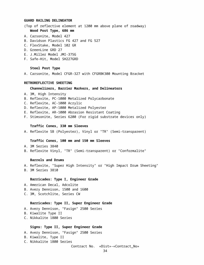
(A) -- A representative of the utility owner shall be present whenever excavation is performed within 1.2 m (4 feet) of the utility. The utility company must be notified by the Contractor 2 days before excavation.
(B) -- No excavation shall be performed within 1.2 m (4 feet) of the utility until the owner, or his representative has located the facility by pot holing, probing, or other means that will locate and identify the facility both horizontally and vertically. The utility company will be allowed 20 working days to perform this work.
Excavation in areas requiring regional notification center investigation shall not be commenced until all utilities in these areas have been located and identified.
Power equipment may be used for excavating construction area sign postholes if it is determined that there are no utility facilities within 1.2 m (4 feet) of the proposed postholes.
10-1.07 COOPERATIONAttention is directed to Section 7-1.14, "Cooperation," and Section 8-1.10, "Utility and Non-Highway Facilities," of the
Standard Specifications and these special provisions.It is anticipated that work by another contractor (Contract No.11-069104) to replace planting and upgrade irrigation in
San Diego on Route 5 from the Old Town Viaduct to San Diego River Bridge (KP R31.2 to KP 32.2) and on Route 8 from Nimitz Boulevard. to Hotel Circle Drive Undercrossing (KP L.8 to KPL3.2) and (Contract No.11-072104) to construct median barriers on Route 8 from Nimitz Blvd. to the Routed 5/8 Separation (KP T1.2 to KPL3.9) may be in progress adjacent to or within the limits of this project during progress of the work on this contract.
Consecutive on-ramp or off-ramps in the same direction of travel shall not be closed simultaneously unless otherwise provided in these special provisions or permitted by the Engineer.
10-1.08 MOBILIZATIONMobilization shall conform to the provisions in Section 11, "Mobilization," of the Standard Specifications.
10-1.09 CONSTRUCTION AREA TRAFFIC CONTROL DEVICES Flagging, signs, and all other traffic control devices furnished, installed, maintained, and removed when no longer
required shall conform to the provisions in Section 12, "Construction Area Traffic Control Devices," of the Standard Specifications and these special provisions.
Category 1 traffic control devices are defined as those devices that are small and lightweight (less than 45 kg), and have been in common use for many years. The devices shall be known to be crashworthy by crash testing, crash testing of similar devices, or years of demonstrable safe performance. Category 1 traffic control devices include traffic cones, plastic drums, portable delineators, and channelizers.
If requested by the Engineer, the Contractor shall provide written self-certification for crashworthiness of Category 1 traffic control devices. Self-certification shall be provided by the manufacturer or Contractor and shall include the following: date, Federal Aid number (if applicable), expenditure authorization, district, county, route and kilometer post of project limits; company name of certifying vendor, street address, city, state and zip code; printed name, signature and title of certifying person; and an indication of which Category 1 traffic control devices will be used on the project. The Contractor may obtain a standard form for self-certification from the Engineer.
Category 2 traffic control devices are defined as those items that are small and lightweight (less than 45 kg), that are not expected to produce significant vehicular velocity change, but may otherwise be potentially hazardous. Category 2 traffic control devices include: barricades and portable sign supports.
Category 2 devices purchased on or after October 1, 2000 shall be on the Federal Highway Administration (FHWA) Acceptable Crashworthy Category 2 Hardware for Work Zones list. This list is maintained by FHWA and can be located at the following internet address: http://safety.fhwa.dot.gov/fourthlevel/hardware/listing.cfm?code=workzone. The Department maintains a secondary list at the following internet address: http://www.dot.ca.gov/hq/traffops/signtech/signdel/pdffiles.htm.
Category 2 devices that have not received FHWA acceptance, and were purchased before October 1, 2000, may continue to be used until they complete their useful service life or until January 1, 2003, whichever comes first. Category 2 devices in use that have received FHWA acceptance shall be labeled with the FHWA acceptance letter number and the name of the manufacturer by the start of the project. The label shall be readable. After January 1, 2003, all Category 2 devices without a label shall not be used on the project.
If requested by the Engineer, the Contractor shall provide a written list of Category 2 devices to be used on the project at least 5 days prior to beginning any work using the devices. For each type of device, the list shall indicate the FHWA acceptance letter number and the name of the manufacturer.
Full compensation for providing self-certification for crashworthiness of Category 1 traffic control devices and for providing a list of Category 2 devices used on the project and labeling Category 2 devices as specified shall be considered as
Contract No. «Dist»-«Contract_No»38
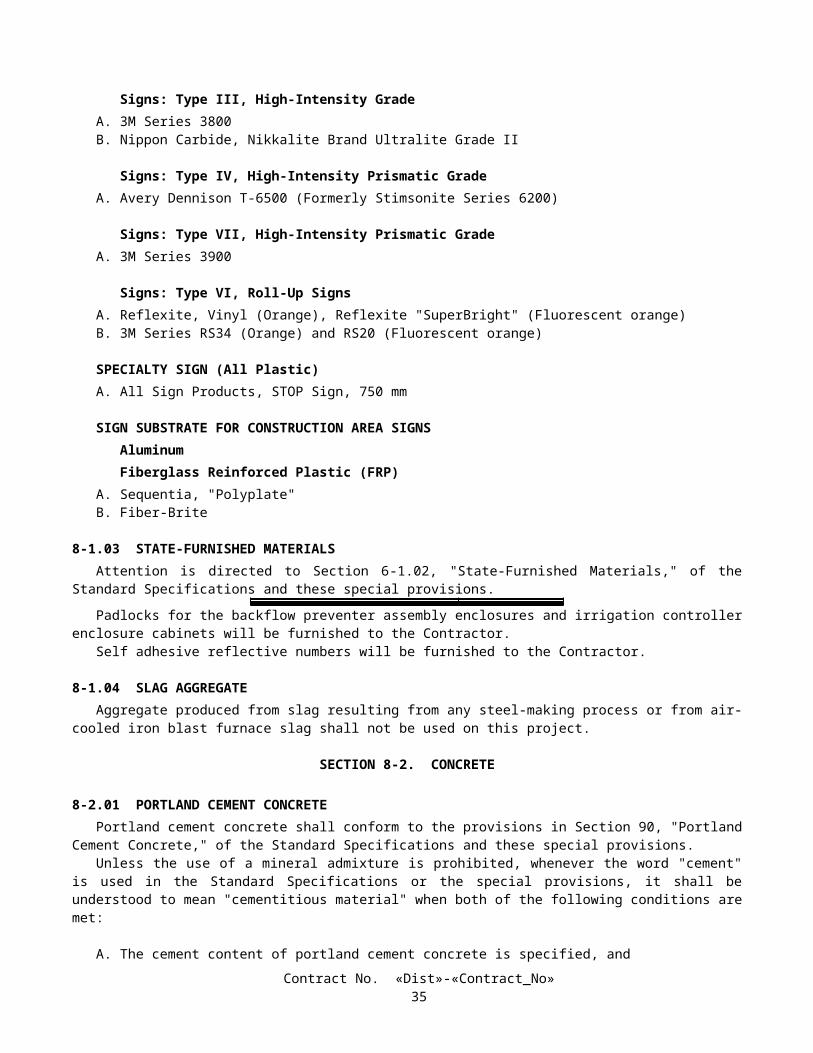
included in the prices paid for the various contract items of work requiring the use of the Category 1 or Category 2 traffic control devices and no additional compensation will be allowed therefor.
10-1.10 CONSTRUCTION AREA SIGNSConstruction area signs shall be furnished, installed, maintained, and removed when no longer required in conformance
with the provisions in Section 12, "Construction Area Traffic Control Devices," of the Standard Specifications and these special provisions.
Attention is directed to the provisions in "Prequalified and Tested Signing and Delineation Materials" of these special provisions. Type II retroreflective sheeting shall not be used on construction area sign panels.
Attention is directed to "Construction Project Information Signs" of these special provisions regarding the number and type of construction project information signs to be furnished, erected, maintained, and removed and disposed of.
The Contractor shall notify the appropriate regional notification center for operators of subsurface installations at least 2 working days, but not more than 14 calendar days, prior to commencing excavation for construction area sign posts. The regional notification centers include, but are not limited to, the following:
Notification Center Telephone NumberUnderground Service Alert-Northern California (USA) 1-800-642-2444
1-800-227-2600Underground Service Alert-Southern California (USA) 1-800-422-4133
1-800-227-2600
Excavations required to install construction area signs shall be performed by hand methods without the use of power equipment, except that power equipment may be used if it is determined there are no utility facilities in the area of the proposed post holes.
Sign substrates for stationary mounted construction area signs may be fabricated from fiberglass reinforced plastic as specified under "Prequalified and Tested Signing and Delineation Materials" of these special provisions.
10-1.11 MAINTAINING TRAFFICAttention is directed to Sections 7-1.08, "Public Convenience," 7-1.09, "Public Safety," and 12, "Construction Area
Traffic Control Devices," of the Standard Specifications and to the provisions in "Public Safety" of these special provisions and these special provisions. Nothing in these special provisions shall be construed as relieving the Contractor from the responsibilities specified in Section 7-1.09.
Attention is directed to "Traffic Plastic Drums," elsewhere in these special provisions regarding the use of plastic drums in place of portable delineators, cones or Type I or II barricades.
No work that would require a lane closure shall be performed.Personal vehicles of the Contractor's employees shall not be parked on the traveled way or shoulders including any
section closed to public traffic.Whenever vehicles or equipment are parked on the shoulder within 1.8 m of a traffic lane, the shoulder area shall be
closed as shown on the plans.Shoulders shall be closed only during the hours shown on the charts included in this section "Maintaining Traffic."
Except work required under Sections 7-1.08 and 7-1.09, work that interferes with public traffic shall be performed only during the hours shown for shoulder closures.
The full width of the traveled way shall be open for use by public traffic when construction operations are not actively in progress.
Designated legal holidays are: January 1st, the third Monday in February, the last Monday in May, July 4th, the first Monday in September, November 11th, Thanksgiving Day, and December 25th. When a designated legal holiday falls on a Sunday, the following Monday shall be a designated legal holiday. When November 11th falls on a Saturday, the preceding Friday shall be a designated legal holiday.
Minor deviations from the requirements of this section concerning hours of work which do not significantly change the cost of the work may be permitted upon the written request of the Contractor, if in the opinion of the Engineer, public traffic will be better served and the work expedited. These deviations shall not be adopted by the Contractor until the Engineer has approved the deviations in writing. All other modifications will be made by contract change order.
Contract No. «Dist»-«Contract_No»39
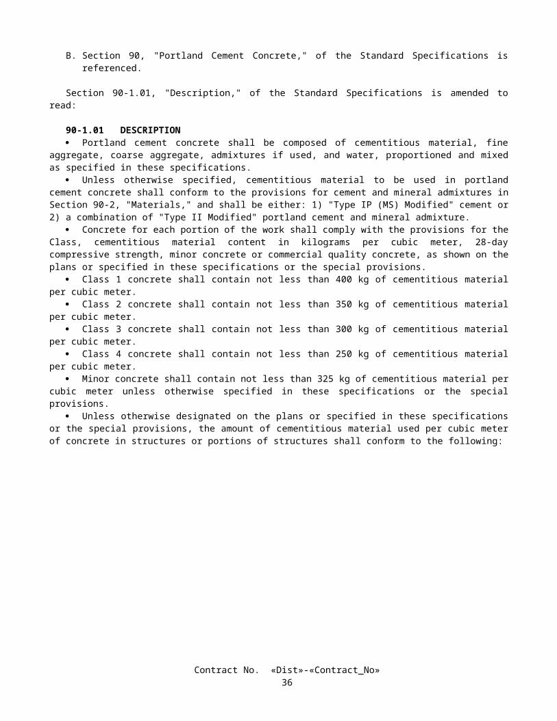
Chart No. 1Shoulder Closure Requirements
Direction: Eastbound SD-8 Location: Sunset Cliffs Blvd. to Morena Blvd. UC
a.m. p.m.FROM HOUR TO HOUR 12 1 2 3 4 5 6 7 8 9 10 11 12 1 2 3 4 5 6 7 8 9 10 11 12Mondays through Thursdays S S S S S S S S S S S S S S
Fridays S S S S S S S S SSaturdays S S S S S S S S S SSundays S S S S S S S S S S S S S S S
Day before designated legal holiday S S S S S S S S SDesignated legal holidays
Legend:S Shoulder may be closed
No lane closure allowed
REMARKS:
KP: L 0.00 / R 0.58 F= LS072114080300KJ
Chart No. 2Shoulder Closure Requirements
Direction: Westbound SD-8 Location: Sunset Cliffs Blvd. to Morena Blvd. UC
a.m. p.m.FROM HOUR TO HOUR 12 1 2 3 4 5 6 7 8 9 10 11 12 1 2 3 4 5 6 7 8 9 10 11 12Mondays through Thursdays S S S S S S S S S S S S S S S
Fridays S S S S S S S SSaturdays S S S S S S SSundays S S S S S S S S S S S S S
Day before designated legal holiday S S S S S S S SDesignated legal holidays
Legend:S Shoulder may be closed
No lane closure allowed
REMARKS:
KP: L 0.00 / R 0.58 F= LS072114080300KJ
Contract No. «Dist»-«Contract_No»40
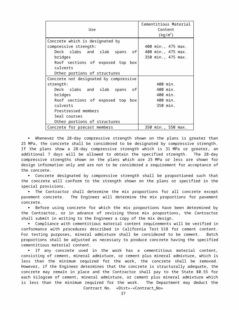
10-1.12 TRAFFIC PLASTIC DRUMSTraffic plastic drums shall conform to the requirements for traffic control devices in Section 12, "Construction Area
Traffic Control Devices," of the Standard Specifications and these special provisions.Traffic plastic drums shall be constructed of low-density polyethylene material and shall be flexible or collapsible upon
impact by a vehicle. The traffic plastic drum shall have a weighted base that will separate from the drum. The base shall be of such shape as to preclude rolling upon impact by a vehicle. The base shall be of sufficient weight to maintain the drum in position and upright. The base or external ballast rings shall not exceed 101.6 mm in height, and drum rings shall not exceed 965.2 mm maximum in diameter. The base or external rings placed over and around the drum, resting on the pavement or ground shall contain the ballast for the drums. Ballast for drums shall be sand or water, except sand shall be used in areas susceptible to freezing. The base shall have drain holes to prevent the accumulation of water. Sand bags shall not be used as ballast for drums.
The body of the traffic plastic drum shall be of a fluorescent orange or predominately orange color. Drums shall be a minimum of 914.4 mm in height above the traveled way, and have at least an 457.2 mm minimum width, regardless of orientation.
The markings on drums shall be horizontal, circumferential, alternating orange and white reflective bands 101.6 to 152.4 mm wide. Each drum shall have a minimum of 2 orange and 2 white bands. The top of the uppermost reflective band shall be no lower than 152.4 mm from the top of the drum. Any non-reflective spaces between the bands shall not exceed 50.8 mm in width. The reflective sheeting shall conform to the provisions in "Approved Traffic Products" elsewhere in these special provisions.
Only one type of traffic plastic drum shall be used on the project. The type of traffic plastic drum proposed for use on the project shall be submitted to the Engineer for approval, prior to placement on the project.
In curvilinear alignment traffic plastic drums shall be used only on one side of the traveled way. Traffic plastic drums shall be placed on the alignment and location shown on the plans, or directed by the Engineer. Traffic plastic drums shall be placed uniformly, straight on tangent alignment and on a true arc on curved alignment. All layout work necessary to place the traffic plastic drums to the proper alignment shall be performed by the Contractor.
If traffic plastic drums are displaced or are not in an upright position, from any cause, the traffic plastic drums shall immediately be replaced or restored to their original location, in an upright position, by the Contractor.
At the option of the Contractor, where portable delineators, cones or Type I or II barricades are specified in the specifications or shown on the plans, traffic plastic drums may be used in place of those portable delineators, cones or Type I or II barricades.
At the completion of the project, traffic plastic drums shall become the property of the Contractor and removed from the site of the work.
Traffic plastic drums shall be installed as shown on the plans when temporary railing (Type K) is placed as required by "Public Safety" elsewhere in these special provisions.
Traffic plastic drums placed in accordance with the provisions in "Public Safety" elsewhere in these special provisions will not be measured nor paid for.
10-1.13 TEMPORARY CRASH CUSHION MODULEThis work shall consist of furnishing, installing, and maintaining sand filled temporary crash cushion modules in
groupings or arrays at each location shown on the plans, as specified in these special provisions or where designated by the Engineer. The grouping or array of sand filled modules shall form a complete sand filled temporary crash cushion in conformance with the details shown on the plans and these special provisions.
Attention is directed to "Public Safety" of these special provisions.
GENERALWhenever the work or the Contractor's operations establishes a fixed obstacle, the exposed fixed obstacle shall be
protected with a sand filled temporary crash cushion. The sand filled temporary crash cushion shall be in place prior to opening the lanes adjacent to the fixed obstacle to public traffic.
Sand filled temporary crash cushions shall be maintained in place at each location, including times when work is not actively in progress. Sand filled temporary crash cushions may be removed during a work period for access to the work provided that the exposed fixed obstacle is 4.6 m or more from a lane carrying public traffic and the temporary crash cushion is reset to protect the obstacle prior to the end of the work period in which the fixed obstacle was exposed. When no longer required, as determined by the Engineer, sand filled temporary crash cushions shall be removed from the site of the work.
MATERIALSAt the Contractor's option, the modules for use in sand filled temporary crash cushions shall be either Energite III Inertial
Modules, Fitch Inertial Modules or TrafFix Sand Barrels manufactured after March 31, 1997, or equal:
Contract No. «Dist»-«Contract_No»41
A. Energite III Inertial Modules, manufactured by Energy Absorption Systems, Inc., One East Wacker Drive, Chicago, IL 60601-2076, Telephone 1-312-467-6750, FAX 1-800-770-6755.
1. Distributor (Northern): Traffic Control Service, Inc., 8585 Thys Court, Sacramento, CA 95828, Telephone 1-800-884-8274, FAX 1-916-387-9734
2. Distributor (Southern): Traffic Control Service, Inc., 1881 Betmor Lane, Anaheim, CA 92805, Telephone 1-800-222-8274, FAX 1-714-937-1070.
B. Fitch Inertial Modules, manufactured by Roadway Safety Service, Inc., 1050 North Rand Road, Wauconda, IL 60084, Telephone 1-800-426-0839, FAX 1-847-487-9820.
1. Distributor (Northern): Traffic Control Service, Inc., 8585 Thys Court, Sacramento, CA 95828, Telephone 1-800-884-8274, FAX 1-916-387-9734
2. Distributor (Southern): Traffic Control Service, Inc., 1881 Betmor Lane, Anaheim, CA 92805, Telephone 1-800-222-8274, FAX 1-714-937-1070.
C. TrafFix Sand Barrels, manufactured by TrafFix Devices, Inc., 220 Calle Pintoresco, San Clemente, CA 92672, Telephone 1-949-361-5663, FAX 1-949-361-9205.
1. Russ Enterprises, Inc., 1533 Berger Drive, San Jose, CA 95112, Telephone 1-408-287-4303, FAX 1-408-287-1929.
2. Statewide Safety, P.O. Box 1440, Pismo Beach, CA 93448, Telephone 1-800-559-7080, FAX 1-805-929-5786.
Modules contained in each temporary crash cushion shall be of the same type at each location. The color of the modules shall be the standard yellow color, as furnished by the vendor, with black lids. The modules shall exhibit good workmanship free from structural flaws and objectionable surface defects. The modules need not be new. Good used undamaged modules conforming to color and quality of the types specified herein may be utilized. If used Fitch modules requiring a seal are furnished, the top edge of the seal shall be securely fastened to the wall of the module by a continuous strip of heavy duty tape.
Modules shall be filled with sand in conformance with the manufacturer's directions, and to the sand capacity in kilograms for each module shown on the plans. Sand for filling the modules shall be clean washed concrete sand of commercial quality. At the time of placing in the modules, the sand shall contain not more than 7 percent water as determined by California Test 226.
Modules damaged due to the Contractor's operations shall be repaired immediately by the Contractor at the Contractor's expense. Modules damaged beyond repair, as determined by the Engineer, due to the Contractor's operations shall be removed and replaced by the Contractor at the Contractor's expense.
INSTALLATIONTemporary crash cushion modules shall be placed on movable pallets or frames conforming to the dimensions shown on
the plans. The pallets or frames shall provide a full bearing base beneath the modules. The modules and supporting pallets or frames shall not be moved by sliding or skidding along the pavement or bridge deck.
A Type R or P marker panel shall be attached to the front of the crash cushion as shown on the plans, when the closest point of the crash cushion array is within 3.6 m of the traveled way. The marker panel, when required, shall be firmly fastened to the crash cushion with commercial quality hardware or by other methods determined by the Engineer.
At the completion of the project, temporary crash cushion modules, sand filling, pallets or frames, and marker panels shall become the property of the Contractor and shall be removed from the site of the work. Temporary crash cushion modules shall not be installed in the permanent work.
MEASUREMENT AND PAYMENTTemporary crash cushion modules placed in conformance with the provisions in "Public Safety" of these special
provisions will not be measured nor paid for.
10-1.14 IRRIGATION CROSSOVERSIrrigation crossovers shall conform to the provisions in Section 20-5, "Irrigation Systems," of the Standard Specifications
and these special provisions.Conduits shall be installed by the directional boring method in conformance with the provisions in Section 20-5.03B,
"Conduit for Irrigation Crossovers," of the Standard Specifications.Contract No. «Dist»-«Contract_No»
42
The diameter of the boring tool shall be only as large as necessary to install conduit. Mineral slurry or wetting solution shall only be used to lubricate the boring tool and to stabilize the soil surrounding the boring path. Mineral slurry or wetting solution shall be water based and environmentally safe.
Residue from directional boring operations shall be handled in the same manner as residue from slot cutting operations described in Section 86-5.01A(5), "Installation Details," of the Standard Specifications.
The directional boring equipment shall have directional control of the boring tool and have an electronic boring tool location detection system. During operation, the directional boring equipment shall be able to determine the location of the tool both horizontally and vertically.
A representative of the Contractor must be in direct charge and control of the directional boring operation at all times.The Engineer shall be notified 2 working days in advance of starting directional boring operations. Directional boring
shall only be performed in the presence of the Engineer unless otherwise notified in writing by the Engineer.Conduits shall be schedule 40 PVC pipe with a minimum of 1137 KPa (psi of 165).Water line crossovers shall conform to the provisions in Section 20-5.03C, "Water Line Crossovers," of the Standard
Specifications.Sprinkler control crossovers shall conform to the provisions in Section 20-5.027D, "Sprinkler Control Crossovers," of
the Standard Specifications.Installation of pull boxes shall conform to the provisions in Section 20-5.027I, "Conductors, Electrical Conduit and Pull
Boxes," of the Standard Specifications. After conductors have been installed, the ends of conduits terminating in pull boxes shall be sealed with an approved type of sealing compound. When no conductors are installed in electrical conduits, pull boxes for irrigation crossovers shall be installed on a foundation of compacted soil and ends of conduits shall be sealed.
The contract price paid per meter for 200 mm conduit shall include full compensation for furnishing all labor, materials, tools, equipment, and incidentals, and for doing all the work involved in irrigation crossover complete in place, including directional boring as shown on the plans, as specified in the Standard Specifications and these special provisions, and as directed by the Engineer.
SECTION 10-2. HIGHWAY PLANTING AND IRRIGATION SYSTEMS
10-2.01 GENERALThe work performed in connection with highway planting and irrigation systems shall conform to the provisions in
Section 20, "Erosion Control and Highway Planting," of the Standard Specifications and these special provisions.The Contractor shall notify the Engineer not less than 72 hours prior to requiring initial access to the existing irrigation
controllers. When the Engineer determines that access to the controllers is required at other times, arrangements will be made to provide this access.
10-2.02 EXISTING HIGHWAY PLANTINGIn addition to the provisions in Section 20 of the Standard Specifications, work performed in connection with existing
highway planting shall be in conformance with the provisions in Section 15, "Existing Highway Facilities," of the Standard Specifications and these special provisions.
Replacement planting shall conform to the requirements specified under "Preservation of Property" of these special provisions.
MAINTAIN EXISTING PLANTSExisting plants shall be maintained as directed by the Engineer. Maintaining existing plants will be paid for as extra
work as provided in Section 4-1.03D of the Standard Specifications.
10-2.03 EXISTING HIGHWAY IRRIGATION FACILITIESThe work performed in connection with the various existing highway irrigation system facilities shall conform to the
provisions in Section 15, "Existing Highway Facilities," of the Standard Specifications and these special provisions.Water shall be maintained in conformance with the provisions in Section 20-5.025, "Maintain Existing Water Supply,"
of the Standard Specifications.
LOCATE EXISTING CROSSOVERS AND CONDUITSExisting crossovers and conduits shown on the plans to be incorporated in the new work shall be located in conformance
with the provisions for locating conduits in Section 20-5.03B, "Conduit for Irrigation Crossovers," of the Standard Specifications.
Unless otherwise directed by the Engineer, existing crossovers and conduits shown on the plans to be incorporated in the new work shall be located prior to performing work on irrigation systems.
Contract No. «Dist»-«Contract_No»43
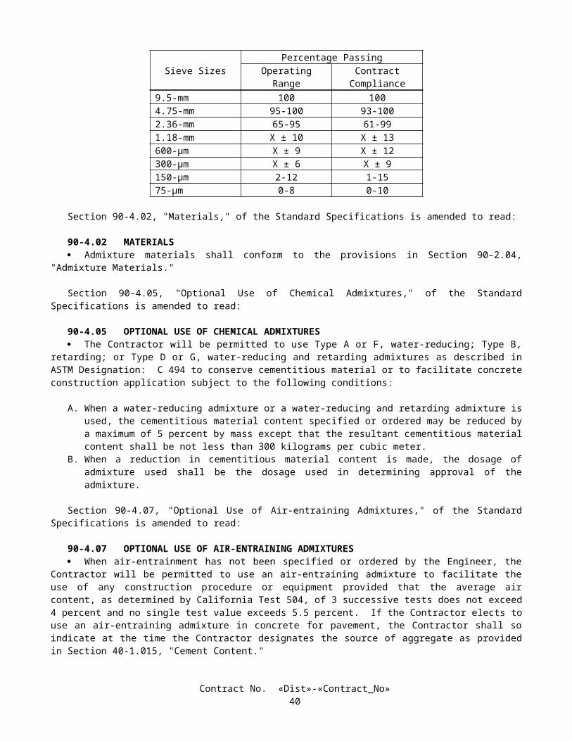
If debris is encountered in the ends of conduits, the debris shall be removed prior to performing other work in the conduits. Removal of debris within the first one meter in these conduits shall be at the Contractor's expense. If debris is encountered in the conduits more than one meter from the ends of the conduits, the additional debris shall be removed as directed by the Engineer and the removal work will be paid for as extra work as provided in Section 4-1.03D of the Standard Specifications.
CHECK AND TEST EXISTING IRRIGATION FACILITIESExisting irrigation facilities that are to remain or to be relocated, and that are to be part of the new irrigation system, shall
be checked for missing or damaged components, and for proper operation prior to performing irrigation system work.A written list of existing irrigation system deficiencies shall be submitted to the Engineer within 5 working days after
checking the existing facilities.Deficiencies found during checking of the existing facilities shall be corrected as directed by the Engineer. Corrective
work ordered by the Engineer will be paid for as extra work as provided in Section 4-1.03D of the Standard Specifications.Existing backflow preventers shall be tested in conformance with the provisions in "Irrigation Systems" of these special
provisions.Length of watering cycles for use of potable water from water meters for checking or testing existing irrigation facilities
shall be as determined by the Engineer.Repairs to the existing irrigation facilities ordered by the Engineer after checking and testing the facilities, and further
repairs required thereafter as ordered by the Engineer, except as otherwise provided under "Existing Highway Irrigation Facilities" of these special provisions, will be paid for as extra work as provided in Section 4-1.03D of the Standard Specifications.
Full compensation for checking and testing existing irrigation facilities, including testing existing backflow preventers, shall be considered as included in the contract prices paid per meter for the various sizes of plastic pipe (supply line) involved and no additional compensation will be allowed therefor.
REMOVE EXISTING IRRIGATION FACILITIESExisting irrigation facilities where shown on the plans to be removed, shall be removed. Facilities that are more than
150 mm below finished grade, excluding facilities to be salvaged, may be abandoned in place.Immediately after disconnecting an existing irrigation facility to be removed or abandoned from an existing facility to
remain, the remaining facility shall be capped or plugged, or shall be connected to a new or existing irrigation facility.Existing sprinklers, remote control valves and valve boxes, where shown on the plans to be removed, shall be salvaged.The Engineer shall be given written notification of the intent to salvage existing irrigation facilities a minimum of
72 hours prior to salvaging these facilities.Salvaged irrigation facilities shall remain the property of the State and shall be delivered to the Engineer.A list of salvaged facilities, including the quantity and size of each item salvaged, shall be included with each delivery.Facilities to be removed, excluding facilities to be salvaged, shall be disposed of in conformance with the provisions in
Section 7-1.13, "Disposal of Material Outside the Highway Right of Way," of the Standard Specifications.
10-2.04 HIGHWAY PLANTINGThe work performed in connection with highway planting shall conform to the provisions in Section 20-4, "Highway
Planting," of the Standard Specifications and these special provisions.
HIGHWAY PLANTING MATERIALSMulch
Mulch shall be wood chips.
Commercial Fertilizer
Commercial fertilizer (slow release) shall be a pelleted or granular form, shall be slow release, and shall fall within the following guaranteed chemical analysis:
Ingredient Percentage
Nitrogen 19Phosphoric Acid 6Water Soluble Potash 12
Contract No. «Dist»-«Contract_No»44
Commercial fertilizer (packet) shall be slow release and shall be in a biodegradable packet form. Packet shall gradually release nutrients throughout a 12 month period. Each packet, as shown in the Plant List of the plans, shall have a mass of 10 g ± 1 g, and shall have the following guaranteed chemical analysis:
Ingredient PercentageNitrogen 20Phosphoric Acid 10Water Soluble Potash 5
ROADSIDE CLEARINGPrior to preparing planting areas or commencing irrigation trenching operations for planting areas, trash and debris shall
be removed from the medians and existing planted areas where existing plants are to remain.In addition to removing trash and debris, the project area shall be cleared as specified herein:
A. Existing ground cover, within proposed planting areas, shall be removed from within the 2-m diameter areas specified for each proposed plant location.
B. Weeds shall be killed and removed within proposed ground cover areas and within the area extending beyond the outer limits of the proposed ground cover areas to the adjacent edges of shoulders, dikes, curbs, sidewalks, walls, existing planting and fences. At those locations where proposed ground cover areas are 3.6 m or more from the adjacent edges of shoulders, dikes, curbs, sidewalks, walls, and fences, the clearing limit shall be 2 m beyond the outer limits of the proposed ground cover areas.
C. Weeds shall be killed and removed within planting areas where plants are to be planted in groups or rows 4.6 m or less apart and from within an area extending 2 m beyond the outer limits of the groups or rows of plants.
D. Weeds shall be killed and removed within an area 2 m in diameter centered at each plant location where the plants are to be planted more than 4.6 m apart and are located outside of ground cover areas.
After the initial roadside clearing is complete, additional roadside clearing work shall be performed as necessary to maintain the areas, as specified above, in a neat appearance until the start of the plant establishment period. This work shall include the following:
A. Trash and debris shall be removed.B. Rodents shall be controlled.C. Weed growth shall be killed and removed before the weeds reach the seed stage of growth or exceed 150 mm in
length.D. Existing ground cover shall be killed and removed from within the 2-m diameter areas specified for each proposed
plant location within the existing ground cover areas.E. Weeds in plant basins, including basin walls, shall be removed by hand pulling, after the plants have been planted.
Weed ControlWeed control shall also conform to the following:
A. Stolon type weeds shall be killed with glyphosate.B. Tumbleweeds shall be removed by hand pulling before the tumbleweeds reach a height of 150 mm.C. Removed weeds and ground cover shall be disposed of outside the highway right of way in conformance with the
provisions in Section 7-1.13, "Disposal of Material Outside the Highway Right of Way," of the Standard Specifications.
PESTICIDESPesticides used to control weeds shall conform to the provisions in Section 20-4.026, "Pesticides," of the Standard
Specifications. Except as otherwise provided in these special provisions, pesticide use shall be limited to the following materials:
DiquatGlyphosateOxadiazon - 50 percent WSP (Preemergent)Oryzalin (Preemergent)
Contract No. «Dist»-«Contract_No»45
Trifluralin (Preemergent)Ammonium Sulfate
Glyphosate shall be used to kill stolon type weeds.Oxadiazon shall be of the emulsifiable concentration or wettable powder type.Prior to the application of preemergents, ground cover plants shall have been planted a minimum of 3 days and shall
have been thoroughly watered.A minimum of 100 days shall elapse between applications of preemergents.Except for ground cover plants, preemergents shall not be applied within 450 mm of plants.Ammonium sulfate shall be used only in areas planted to Carpobrotus. Ammonium sulfate shall not be applied in a
manner that allows the pesticides to come in contact with trees or shrubs.If the Contractor elects to request the use of other pesticides on this project, the request shall be submitted, in writing, to
the Engineer not less than 15 days prior to the intended use of the other pesticides. Except for the pesticides listed in these special provisions, no pesticides shall be used or applied without prior written approval of the Engineer.
Pesticides shall not be applied within the limits of the plant basins. Pesticides shall not be applied in a manner that allows the pesticides to come in contact with the foliage and woody parts of the plants.
PREPARING PLANTING AREASPlants adjacent to drainage ditches shall be located so that after construction of the basins, no portion of the basin walls
shall be less than the minimum distance shown on the plans for each plant involved.
PLANTINGCommercial fertilizer and iron sulfate shall be applied or placed at the time of planting and at the rates shown on the
plans.Attention is directed to "Irrigation Systems Functional Test" of these special provisions regarding functional tests of the
irrigation systems. Planting shall not be performed in an area until the functional test has been completed for the irrigation system serving that area.
Quantities of commercial fertilizer packets will be measured by the tablet as determined from actual count in place.
PLANT ESTABLISHMENT WORKThe plant establishment period shall be Type 1 and shall be 500 working days.Commercial fertilizer (slow release) shall be applied to trees, shrubs, and ground cover during the first week of April,
July and October of each year. Commercial fertilizer shall be applied at the rates shown on the plans and shall be spread with a mechanical spreader wherever possible.
The center to center spacing of replacement plants for unsuitable ground cover plants shall be determined by the number of completed plant establishment working days at the time of replacement and the original spacing in conformance with the following:
ORIGINAL SPACING (Millimeters)
SPACING OF REPLACEMENT GROUND COVER PLANTS(Millimeters)
Number of Completed Plant Establishment Working Days1-125 126-190 191-End of Plant
Establishment300 300 230 150
During the plant establishment period, the plants shall be watered utilizing the Remote Irrigation Control System (RICS) software program. Two watering schedules shall be submitted to the Engineer for use during the plant establishment period. The Caltrans Water Manager shall enter both schedules into the RICS computer program. The first watering schedule shall be utilized for the first 125 days of plant establishment. After 125 days of plant establishment, the second watering schedule shall be implemented.
A second watering shall be based on individual plant water requirement, local climatic conditions, and irrigation system precipitation rates and shall operate automatically interfacing directly with the appropriate California Irrigation Management Information System (CIMIS) weather station. The second watering schedule shall be prepared by a Certified Landscape Irrigation Auditor (CLIA) sanctioned by the Irrigation Association. The second watering schedule shall be manually entered into each irrigation controller by the Contractor for use during standalone mode and shall be updated seasonally as needed.
Weeds within plant basins, including basin walls, shall be controlled by hand pulling.Weeds within ground cover areas and outside of plant basins shall be controlled by killing.
Contract No. «Dist»-«Contract_No»46
At the option of the Contractor, plants of a larger container size than those originally specified may be used for replacement plants during the first 125 working days of the plant establishment period. The use of plants of a larger container size than those originally specified for replacement plants shall be at the Contractor's expense.
After 125 working days of the plant establishment period have been completed, replacement of plants, except for ground cover plants, shall be No. 5 size for No. one size plants; and other plant replacement plants shall be the same size as originally specified.
When ordered by the Engineer, one application of a preemergent pesticide conforming to the provisions in "Pesticides" of these special provisions, shall be applied between 40 and 50 working days prior to completion of the plant establishment period. This work will be paid for as extra work as provided in Section 4-1.03D of the Standard Specifications.
The final inspection shall be performed in conformance with the provisions in Section 5-1.13, "Final Inspection," of the Standard Specifications and shall be completed a minimum of 20 working days before the estimated completion of the contract.
10-2.05 IRRIGATION SYSTEMSIrrigation systems shall be furnished and installed in conformance with the provisions in Section 20-5, "Irrigation
Systems," of the Standard Specifications, except materials containing asbestos fibers shall not be used.Attention is directed to the provisions in "Obstructions" of these special provisions, regarding work over or adjacent to
existing underground facilities. Excavation for proposed irrigation facilities shall not be started until the existing underground facilities have been located.
Pipe supply lines shall be pressure tested in conformance with the provisions in Section 20-5.03H, "Pressure Testing," of the Standard Specifications, except the pipe (supply line) on the discharge side of the control valve shall be tested by Method B as specified in Section 20-5.03H(2), "Method B," of the Standard Specifications.
Only pipeline trenches and excavation pits for supply lines being supplied from one water service point shall be open at one time. After pressure testing is complete, trenches and pits excavated for pipe supply lines, being supplied from one water service point, shall be backfilled prior to commencing excavations for pipe supply lines being supplied from another water service point.
Gate valves, 75 mm and larger in size, shall be furnished with a square lug and shall be operated by use of long shank keys. Prior to acceptance of the contract, 3 long shank keys shall be delivered to the Engineer.
Gate valves 75 mm and larger in size shall be flanged type gate valves and shall have a solid brass wedge.Pipe flanges used to connect plastic or metal pipe to gate valves shall be metal. Plastic flanges will not be allowed.
VALVE BOXESValve boxes shall conform to the provisions in Section 20-2.24, "Valve Boxes," of the Standard Specifications, except as
otherwise provided herein.Valve boxes shall be precast portland cement concrete, fiberglass or reinforced plastic.Covers for plastic and concrete valve boxes shall be glass fiber reinforced plastic or plastic.Valve boxes shall be identified on the top surface of the covers by branding the appropriate abbreviations for the
irrigation facilities contained in the valve boxes as shown on the plans. Valve boxes that contain remote control valves shall be identified by the appropriate letters and numbers (controller and station numbers). The letters and numbers shall be 50 mm in height.
ELECTRIC AUTOMATIC IRRIGATION COMPONENTS
Irrigation ControllersIrrigation controllers shall be Rain Bird Maxicom controllers and shall communicate by cellular interface.Arrangements have been made to insure that any successful bidder can obtain the specified equipment listed below from
Pacific Technical Services, 23372 South Pointe Drive, Suite B, Laguna Hills, California, 92653, telephone (949) 837-4737.The quoted prices and equipment are as follows:
Contract No. «Dist»-«Contract_No»47
EQUIPMENT DESCRIPTION QUOTED PRICE SALES TAX EXTENDED PRICE
QUANTITYAT THIS PRICE
28 Channel CCU:Model No. - C28 RMOP28 Channel Cluster Control Unit Assembly with Radio, Modem, Omni Pole Antenna Assembly, Rain Shut Off Assembly, Cellular Interface Cable
$9,671.00 $750.00 $10,421.00 1
24 Station Irrigation Controller:Model No. - RB2-24 ESP 24 Station Satellite Controller Assembly with Radio, Modem LoPro Antenna Assembly and Master Valve Relays
$3,440.00 $267.00 $3,707.00 1
16 Station Irrigation Controller:Model No. - RB2-16 ESP 16 Station Satellite Controller Assembly with Radio, Modem LoPro Antenna Assembly and Master Valve Relays
$3,260.00 $253.00 $3,513.00 2
Hand Held Remote Control:Model No. - TRC-XREC-KHand Held Remote Control, TRC Transmitter and Receiver
$2,045 $158 $2,203 1
Irrigation Software Training:16 hours of Maxicom training $1,840.00 $0 $1.840.00 1
Prices are guaranteed by Pacific Technical Services for one year from the date of the quote, August 16, 2000.The contract unit price paid for 28 channel Irrigation Cluster Control Unit shall include full compensation for furnishing
all labor, materials, tools, equipment, and incidentals, and for doing all the work involved in providing and installing the CCU, complete in place. as shown on the plans, as specified in these special provisions, and as directed by the Engineer.
The contract unit price paid for hand held remote control shall include full compensation for furnishing all labor, materials, tools, equipment, and incidentals, and for doing all the work involved in providing hand held remote control, complete in place, as shown on the plans, as specified in these special provisions, and as directed by the Engineer.
The contract unit price paid for irrigation software training shall include full compensation for furnishing all labor, materials, tools, equipment, and incidentals, and for doing all the work involved in providing 16 hours of Maxicom training, as shown on the plans, as specified in these special provisions, and as directed by the Engineer.
Attention is directed to the provisions in Section 10-3, "Electrical Systems," of these special provisions, regarding electrical power for irrigation controllers and irrigation controller enclosure cabinets.
Electric Remote Control ValvesElectric remote control valves shall conform to the provisions in Section 20-2.23, "Control Valves," of the Standard
Specifications and the following:
A. Valves shall be glass filled nylon, brass or bronze construction.B. Valves shall be angle pattern (bottom inlet) or straight pattern (side inlet) as shown on the plans.C. Valves shall be equipped with a self-flushing feature manufactured to be used with reclaimed water.
Contract No. «Dist»-«Contract_No»48
Pull BoxesPull box installations shall conform to the provisions in Section 20-5.027I, "Conductors, Electrical Conduits and Pull
Boxes," of the Standard Specifications.
ConductorsLow voltage, as used in this section "Conductors," shall mean 36 V or less.Low voltage control and neutral conductors in pull boxes and valve boxes, at irrigation controller terminals, and at
splices shall be marked with adhesive cloth wrap-around markers.Markers for the control conductors shall be identified with the appropriate number or letter designations of irrigation
controllers and station numbers. Markers for neutral conductors shall be identified with the appropriate number or letter designations of the irrigation controllers.
The color of low voltage neutral and control conductor insulation, except for the striped portions, shall be homogeneous throughout the entire thickness of the insulation.
Insulation for conductors may be UL listed polyethylene conforming to UL44 test standards with a minimum insulation thickness of 1.05 mm for wire sizes 10AWG and smaller.
At the option of the Contractor, other types of splice sealing materials and methods may be used provided other materials and methods have been approved in writing by the Engineer prior to installation of the connectors.
Flow Sensor CableFlow sensor cable shall be UL listed as Type TC and meet the requirements of ICEA/NEMA, 600-V control cable,
90°C, and the following:
A. The cable shall consist of two No. 16, minimum, stranded copper conductors. Each conductor shall be insulated with 0.48-mm, minimum nominal thickness, color coded, polypropylene or polyethylene material. Color coding shall distinguish each conductor.
B. The shield shall be either tinned copper braid or aluminized polyester film with a nominal 20 percent overlap. Where the film is used, a No. 18 or larger, stranded, tinned, copper drain wire shall be placed between the insulated conductors and the shield and in contact with the conductive surface of the shield.
C. The jacket shall be black polyvinyl chloride with minimum ratings of 600 V and 90°C and a minimum nominal thickness of 1.25 mm. The cable jacket shall be marked with the manufacturer’s name or trademark, insulation type designation, number of conductors and conductor size, and voltage and temperature ratings.
D. The finished outside diameter of the cable shall not exceed 8.9 mm.E. The capacitance, as measured between any conductor and the other conductors and the shield, shall not exceed 88 pf
per meter at 1000 Hz.F. The cable run between remote control valve (master) with flow meter and the irrigation controller shall be
continuous without splices.
Full compensation for flow sensor cable shall be considered as included in the contract lump sum price paid for control and neutral conductors and no additional compensation will be allowed therefor.
REMOTE CONTROL VALVE (MASTER) WITH FLOW METERRemote control valve (master) with flow meter shall be installed in accordance with the details shown on the plans and
the requirements of these special provisions.The remote control valve (master) with flow meter shall consist of a remote control valve with flow meter and pressure
reducing device, and all appurtenances required to complete the assembly in place as shown on the plans.The master remote control valve with flow meter shall be a globe type valve, consisting of diaphragm actuated hydraulic
control valve with 0.3 amp, 3-way solenoid control and built-in impeller type flow meter and brass pressure regulating pilot. Remote control valves (master) shall normally be closed.
The valves shall conform to the following:
A. Valves shall be pressure rated to 1206 kpa and shall be equipped with 8-volt, cast iron, flange type end connections which conform to ANSI Standard: B16.1, Class 125.
B. Impeller driven flow meters shall be accurate to plus or minus 2 percent of the actual flow.C. Flow meters shall be equipped with an electric pulse transmitter for remote monitoring, factory preset to provide a
pulse signal every 38 liters. Flow meter 50 mm in size shall have a flow range between 45 and 567 liters per minute.D. Valves shall operate on the 24-volt AC voltage supplied from the irrigation controller or controllers.
Contract No. «Dist»-«Contract_No»49
E. Main valve bodies and covers shall be of cast iron construction with internal and external epoxy coatings.F. Valve shall be equipped with brass fitting and copper tubing.
Flow sensor cable and two low voltage conductors shall be installed in conduit between each master remote control valve with flow meter and irrigation controller as shown on the plans. Flow sensor cable shall conform to the provisions in "Flow Sensor cable," elsewhere in these special provisions.
Enclosure and concrete pad shall conform to the provisions in "Assembly Enclosure," elsewhere in these special provisions.
The contract unit price paid for remote control valve (master) with flow meter shall include full compensation for furnishing all labor, materials, tools, equipment, and incidentals, and for doing all the work involved in remote control valve (master) with flow meter, complete in place, except for enclosure and concrete pad, as shown on the plans, as specified in the Standard Specifications and these special provisions, and as directed by the Engineer.
IRRIGATION SYSTEMS FUNCTIONAL TESTFunctional tests for the remote irrigation controller system (RICS) and associated automatic irrigation systems shall
conform to the provisions in Section 20-5.027J, "Testing," of the Standard Specifications and these special provisions. Functional test shall be conducted in the presence of the Engineer.
Two functional tests shall be performed, one without and one with connection to the remote irrigation controller system central computer. Both tests shall consist of demonstrating to the Engineer, through one complete cycle of the irrigation controllers, but not less than 5 consecutive working days of operation, in the automatic mode, that the associated automatic components of the irrigation systems operate properly.
The Contractor shall notify the Engineer not less than 2 weeks prior to starting the functional tests for the remote irrigation control system.
The existing remote irrigation controller system central computer is located at the Kearny Mesa Water Manager’s Office at 7181 Opportunity Road, Room 8, San Diego, California, 92111.
Associated automatic components for both tests shall include, but not limited to, new and existing remote control valve actuator systems, irrigation controllers, remote control valves, conductors, flow sensors, and rain sensors. Associated automatic components for the second test shall include, but not be limited to, new and existing irrigation software programs, cellular phone systems, hand held remote controls, local two way radio communication between CCU and satellite units, and flow alarms for high, low, zero, and maximum mainline flows.
The first test shall be performed prior to planting the plants and shall consist of testing the irrigation controllers and associated automatic irrigation systems without connection to the remote irrigation controller system base station. Upon completion of a satisfactory functional test, and correction of the deficiencies, the plants to be planted in the areas watered by the irrigation system may be planted, provided the planting areas have been prepared as specified in these special provisions.
The second test shall be performed prior to the start of plant establishment and shall consist of testing the irrigation controllers (satellite) and associated automatic irrigation systems with connection to the remote irrigation controller system central computer. As part of the second test, a remote irrigation controller system watering schedule and liters per minute data base for each valve shall be submitted in written form, for each irrigation controller (satellite unit) to the Engineer. The Engineer will enter the watering schedule into the irrigation software program, and a computer printout will be made available to the Contractor for verification. If the Engineer determines the submitted watering schedule is unacceptable, a revised watering schedule shall be submitted to the Engineer for approval within 5 working days. Also as part of the second test, the Contractor shall demonstrate to the Engineer that the remote irrigation controller system central computer detects and reports the high mainline flow alarms. Upon completion of a satisfactory test, including correction of deficiencies, the plant establishment period may begin, provided planting work as specified in these special provisions has been completed except for plant establishment work.
If existing and new automatic components of the irrigation systems, including remote irrigation controller system central computer components, fail a functional test, the components shall be repaired. Repairs shall be at the Contractor's expense, except for repairs to an existing central computer (personal computer, printer, mouse, keyboard, cables, and software) which will be paid for as extra work as provided in Section 4-1.03D of the Standard Specifications. Testing shall be repeated until satisfactory operation is obtained.
Repair or replacement of existing irrigation facilities due to unsatisfactory performance shall conform to the provisions in Section 20-5.025, "Maintain Existing Water Supply," of the Standard Specifications and "Existing Highway Irrigation Facilities" of these special provisions.
PIPE
Copper PipeCopper pipe shall be seamless, Type K hard drawn tubing.
Contract No. «Dist»-«Contract_No»50
Copper pipe supply lines installed between water meters and backflow preventer assemblies shall be installed not less than 450 mm below finished grade, measured to the top of the pipe.
Plastic PipePlastic pipe supply lines shall be polyvinyl chloride (PVC) 1120 or 1220 pressure rated pipe with the minimum pressure
rating (PR) shown on the plans.Plastic pipe supply lines and fittings that are 75 mm or larger in diameter on the supply side of control valves shall be the
rubber ring gasket type, except when pressure rating (PR) 315 plastic pipe supply line is required.Plastic pipe supply lines less than 75 mm in diameter shall have solvent cemented type joints. Primers shall be used on
the solvent cemented type joints.Plastic pipe supply lines (main) shall have a minimum cover of 0.45 m.A nonhardening joint compound shall be used in place of the pipe thread sealant tape conforming to the provisions in
Section 20-5.03E, "Pipe," of the Standard Specifications. Joint compounds shall be applied in conformance with the manufacturer's recommendations.
Fittings for plastic pipe supply lines with a pressure rating (PR) of 315 shall be Schedule 80.
FERTILIZER COUPLINGFertilizer coupling shall be in accordance with the details shown on the plans and the requirements of these special
provisions.The fertilizer coupling shall consist of an aluminum cam and groove coupling with dust cap, gate valve and all piping
required to complete the assembly in place as shown on the plans.The contract unit paid for fertilizer coupling shall include full compensation for furnishing all labor, materials, tools,
equipment, and incidentals, and for doing all the work involved in fertilizer coupling, complete in place, including gate valve and valve box, as shown on the plans, as specified in the Standards Specifications and these special provisions, and as directed by the Engineer.
BACKFLOW PREVENTER ASSEMBLIESBackflow preventers shall conform to the provisions in Section 20-2.25, "Backflow Preventers," of the Standard
Specifications and these special provisions.Pressure loss through the backflow preventers shall not exceed the following:
BACKFLOW PREVENTER SIZE(millimeters)
FLOW RATE(Liters per second)
PRESSURE LOSS(kPa)
50 7 30
Backflow preventer assemblies shall be painted with a minimum of 2 applications of a commercial quality enamel paint. The color of the paint shall be light brown.
When backflow preventer assembly enclosures are specified, the portland cement concrete pads for the enclosures will be paid for in conformance to the provisions in "Backflow Preventer Assembly Enclosures" of these special provisions.
BACKFLOW PREVENTER ASSEMBLY ENCLOSUREEnclosures shall be fabricated of structural steel angles and flattened expanded metal and shall be installed over
backflow preventer assemblies on a portland cement concrete pad in conformance with the details shown on the plans. There shall be 50 mm minimum clearance between the backflow preventer assembly and the backflow preventer assembly enclosure. The concrete pad shall extend a minimum of 50 mm beyond the outer limits of the backflow preventer assembly enclosure, unless otherwise shown on the plans or as specified in these special provisions.
Expanded metal for sides, ends and top panels shall be fabricated from No. 9 expanded metal. The flattened expanded metal openings shall be approximately 20 mm by 45 mm in size.
Expanded metal panels shall be attached to the steel frames by a series of welds, not less than 6.4 mm in length and spaced not more than 100 mm on centers, along the edges of the enclosures.
Enclosure door handles shall have provisions for padlocking in the latched position. Padlocks will be State-furnished as provided under "State-furnished Materials" of these special provisions.
Enclosures shall be galvanized, after fabrication, in conformance with the provisions in Section 75-1.05, "Galvanizing," of the Standard Specifications.
Portland cement concrete for the concrete pad shall be minor concrete conforming to the provisions in Section 90 -10, "Minor Concrete," of the Standard Specifications.
Contract No. «Dist»-«Contract_No»51
Hold down bolt assemblies shall be galvanized and shall be installed when the portland cement concrete pad is still plastic. Nuts shall be hexagonal and washers shall be the lock type.
Contract No. «Dist»-«Contract_No»52
Enclosures shall be painted with one application of a commercial quality pre-treatment, vinyl wash primer and a minimum of one application of a commercial quality, exterior enamel for metal. The finish color shall be light brown.
The quantity of backflow preventer assembly enclosures will be measured by the unit as determined from actual count in place.
The contract unit price paid for the backflow preventer assembly enclosure shall include full compensation for furnishing all labor, materials, tools, equipment, and incidentals, and for doing all the work involved in furnishing and installing a backflow preventer assembly enclosure, complete in place, including constructing the portland cement concrete pad, as shown on the plans, as specified in the Standard Specifications and these special provisions, and as directed by the Engineer.
TESTING BACKFLOW PREVENTERSNew backflow preventers installed by the Contractor and existing backflow preventers to remain in place shall be tested
for proper operation in conformance with the provisions in Section 20-5.03J, "Check and Test Backflow Preventers," of the Standard Specifications and these special provisions.
Tests for new backflow preventers shall be satisfactorily completed after installation of the backflow preventer assembly and before operation of the irrigation systems. Existing backflow preventers shall be tested, and repaired if required, when existing irrigation facilities are checked.
Repair of existing backflow preventers will be paid for as extra work as provided in Section 4-1.03D of the Standard Specifications when ordered by the Engineer, except damage caused by the Contractor's operations.
New and existing backflow preventers shall be retested one year after the satisfactory completion of the previous test or 10 days prior to completion of the plant establishment period, whichever occurs first.
Testing existing and relocated backflow preventers will be paid for in conformance with the provisions in "Checking and Testing Existing Irrigation Facilities" of these special provisions.
SPRINKLERSSprinklers shall conform to the type, pattern, material, and operating characteristics listed in the "Sprinkler Schedule"
shown on the plans.Drain pipe for Type C-2 modified sprinklers shall be commercially available rigid perforated polyvinyl chloride (PVC)
pipe with the holes spaced not more than 150 mm on center on one side of the pipe.The drain pipe shall be installed around the sprinkler nipple within the plant basin as shown on the plans with the holes
facing the plant root ball.Pea gravel for backfilling the drain pipe shall be naturally rounded aggregate, clean, washed, dry and free from clay or
organic material. The pea gravel shall conform to the following grading:
Sieve or Screen Size Percentage passing19 mm 100
12.5 mm 90-1009.5 mm 40-704.75 mm 0-152.36 mm 0-3
Full compensation for drain pipe and pea gravel for type C-2 modified sprinklers shall be considered as included in the contract unit price paid for sprinkler (type C-2 mod) and no additional compensation will be allowed therefor.
FINAL IRRIGATION SYSTEM CHECKA final check of existing and new irrigation facilities shall be performed not more than 20 working days prior to
acceptance of the contract.The length of watering cycles using potable water measured by water meters for the final check of irrigation facilities
will be determined by the Engineer.Remote control valves shall be checked for automatic performance when the controllers are in automatic mode.Unsatisfactory performance of irrigation facilities installed or modified by the Contractor shall be repaired and rechecked
at the Contractor's expense until satisfactory performance is obtained, as determined by the Engineer.Repair or replacement of existing irrigation facilities due to unsatisfactory performance shall conform to the provisions
in "Existing Highway Irrigation Facilities" of these special provisions.Nothing in this section "Final Irrigation System Check" shall relieve the Contractor of full responsibility for making
good or repairing defective work or materials found before the formal written acceptance of the entire contract by the Director.
Contract No. «Dist»-«Contract_No»53
Full compensation for checking the irrigation systems prior to the acceptance of the contract shall be considered as included in the contract lump sum price paid for plant establishment work and no additional compensation will be allowed therefor.
SECTION 10-3. ELECTRICAL SYSTEMS
Contract No. «Dist»-«Contract_No»54
10-3.01 DESCRIPTIONIrrigation controller enclosure cabinet and electric service (irrigation) shall conform to the provisions in Section 86,
"Signals, Lighting and Electrical Systems," of the Standard Specifications and these special provisions.
10-3.02 CONDUITConduit to be installed underground shall be Type 3 unless otherwise specified.The conduit in a foundation and between a foundation and the nearest pull box shall be Type 3.Conduit sizes shown on the plans and specified in the Standard Specifications and these special provisions are referenced
to metallic type conduit. When rigid non-metallic conduit is required or allowed, the nominal equivalent industry size shall be used as shown in the following table:
Size Designation for Metallic Type Conduit Equivalent Size for Rigid Non-metallic Conduit21 2027 2541 4053 5063 6578 75103 100
When Type 3 conduit is placed in a trench (not in pavement or under portland cement concrete sidewalk), after the bedding material is placed and the conduit is installed, the trench shall be backfilled with commercial quality concrete, containing not less than 250 kg of portland cement per cubic meter, to not less than 100 mm above the conduit before additional backfill material is placed.
After conductors have been installed, the ends of conduits terminating in pull boxes, and irrigation controller enclosure cabinets shall be sealed with an approved type of sealing compound.
10-3.03 PULL BOXESGrout shall not be place in the bottom of pull boxes.Where the sump of an existing pull box is disturbed by the Contractor's operation, the sump shall be reconstructed as
shown on Standard Plan ES-8.
10-3.04 CONDUCTORS AND WIRINGSplices of conductors shall be insulated with heat-shrink tubing of the appropriate size after thoroughly painting the
spliced conductors with electrical insulating coating.The minimum insulation thickness, at any point, for Type USE, RHH or RHW wire shall be 1.0 mm for conductor sizes
No. 14 to No. 10, inclusive, and 1.3 mm for No. 8 to No. 2, inclusive. The minimum insulation thickness, at any point, for Type THW and TW wires shall be 0.69 mm for conductor sizes No. 14 to No. 10, inclusive, 1.02 mm for No. 8, and 1.37 mm for No. 6 to No. 2, inclusive.
10-3.05 ELECTRIC SERVICE (IRRIGATION)Electric service (irrigation) shall be from the service points to the irrigation controllers (IC) and to the spaces provided in
the irrigation controller enclosure cabinets (CEC) for irrigation controllers as shown on the plans.The inscription on other nameplates shall be the identifying letter designation used on the plans and in these special
provisions, or shall be as directed by the Engineer.
10-3.06 IRRIGATION CONTROLLER ENCLOSURE CABINETIrrigation controller enclosure cabinets (CEC) shall be constructed and the equipment within the cabinets shall be
installed in conformance with the details shown on the plans, the provisions in the Standard Specifications, and these special provisions.
Irrigation controller enclosure cabinets shall be of metal construction conforming to the details for empty Type P signal cabinets shown on Standard Plans ES-3A and ES-3C, except that the fluorescent interior light, police panels, and shelves shall not be provided, unless otherwise shown on the plans. Cabinets shall be provided with cross ventilation, roof ventilation or a combination of both. The anchorage arrangement shall be inside the cabinet as shown on the plans. Dimensions of the cabinet shall be suitable for the equipment to be installed as shown on the plans and specified in these special provisions.
Contract No. «Dist»-«Contract_No»55
Irrigation controller enclosure cabinets shall be fabricated in conformance with the provisions in Section 86-3.04A, "Cabinet Construction," of the Standard Specifications.
Irrigation controller enclosure cabinets shall be fabricated of stainless steel.Irrigation controller enclosure cabinet doors shall not be furnished with integral door locks. Irrigation controller
enclosure cabinet door handles shall have provisions for padlocking in the latched position. Padlocks will be State-furnished as provided under "Materials" of these special provisions.
Inside of the doors shall have provisions for storage of the irrigation plans.Duplex convenience receptacles shall have ground-fault circuit interruption as defined by the Code. Circuit interruption
shall occur on 6 mA of ground-fault current and shall not occur on less than 4 mA. Receptacles shall be installed in a weatherproof housing with rainproof lift covers.
Solid-state automatic shut-off rain sensor units shall be installed for the irrigation controller enclosure cabinets where shown on the plans. Rain sensor units shall automatically interrupt the master remote control valves when approximately 3 mm of rain has fallen. The irrigation system shall automatically be enabled again when the accumulated rainfall evaporates from the rain sensor unit collection cup. Rain sensor units shall be rated 24 V (ac) to 30 V (ac). Static charge protection shall be included to protect against lightning damage.
Equipment, except for field wiring, shall be installed in the cabinet in a shop prior to field installation.
10-3.07 REMOVING, REINSTALLING OR SALVAGING ELECTRICAL EQUIPMENTSalvaged electrical materials shall be hauled to the District Recycle Yard, located near the south end of the Route 15
High Occupancy Vehicle Lanes (HOV) in the City of San Diego, San Diego County and stockpiled.The Contractor shall provide the equipment, as necessary, to safely unload and stockpile the material. A minimum of
2 working days' notice shall be given to the Engineer and the District Electrical Recycle Coordinator, telephone (619) 688-6842,prior to delivery.
10-3.08 PAYMENTFull compensation for hauling and stockpiling electrical materials shall be considered as included in the contract price
paid for the item requiring the material to be salvaged and no additional compensation will be allowed therefor.The contract lump sum price paid for electric service (irrigation) shall include full compensation for furnishing all labor,
materials, tools, equipment, and incidentals, and for doing all the work involved in installing electric service (irrigation) for irrigation controllers, complete in place, including conductors, conduit and pull boxes to the pull box adjacent to irrigation controller enclosure cabinets and irrigation controllers, as shown on the plans, as specified in these special provisions, and as directed by the Engineer.
The contract unit price paid for irrigation controller enclosure cabinet shall include full compensation for furnishing all labor, materials, tools, equipment (including rain sensor units), and incidentals, and for doing all the work involved in fabricating and installing irrigation controller enclosure cabinets, complete in place, including constructing foundations, pads, conductors and conduits to pull box adjacent to cabinets, and installing equipment within the cabinets, except controllers, as shown on the plans, as specified in the Standard Specifications and these special provisions, and as directed by the Engineer.
Contract No. «Dist»-«Contract_No»56