Embed Size (px)
Citation preview
EDIT DATE DESIG.
Small Machine operator’s panelConnection manual
TITLE
DESCRIPTION
DRAW.NO. A-83122E
SHEET
CUST
1 / 19
01 A.KOIKE03.03.20
A.KOIKE03.03.3102 13,14/19
T.KOIKE
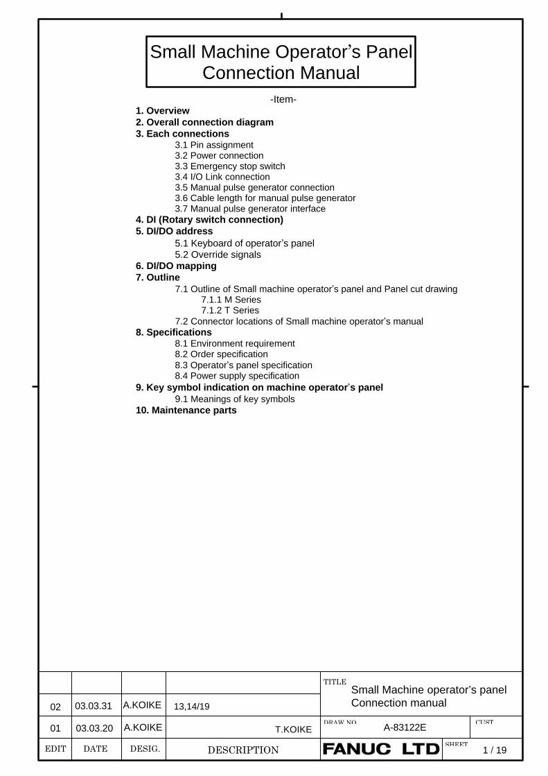
-Item-1. Overview2. Overall connection diagram3. Each connections
3.1 Pin assignment3.2 Power connection3.3 Emergency stop switch3.4 I/O Link connection3.5 Manual pulse generator connection3.6 Cable length for manual pulse generator3.7 Manual pulse generator interface
4. DI (Rotary switch connection)5. DI/DO address
5.1 Keyboard of operator’s panel5.2 Override signals
6. DI/DO mapping7. Outline
7.1 Outline of Small machine operator’s panel and Panel cut drawing7.1.1 M Series7.1.2 T Series
7.2 Connector locations of Small machine operator’s manual8. Specifications
8.1 Environment requirement8.2 Order specification8.3 Operator’s panel specification8.4 Power supply specification
9. Key symbol indication on machine operator’s panel9.1 Meanings of key symbols
10. Maintenance parts
Small Machine Operator’s PanelConnection Manual
EDIT DATE DESIG.
Small Machine operator’s panelconnection manual
TITLE
DESCRIPTION
DRAW.NO. A-83122E
SHEET
CUST
2 /
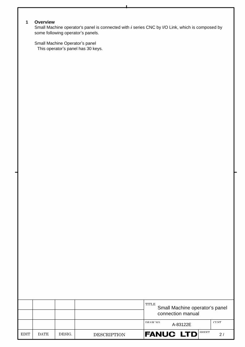
1 OverviewSmall Machine operator's panel is connected with i series CNC by I/O Link, which is composed bysome following operator’s panels.
Small Machine Operator’s panelThis operator’s panel has 30 keys.
EDIT DATE DESIG.
Small Machine operator’s panelconnection manual
TITLE
DESCRIPTION
DRAW.NO. A-83122E
SHEET
CUST
3 /
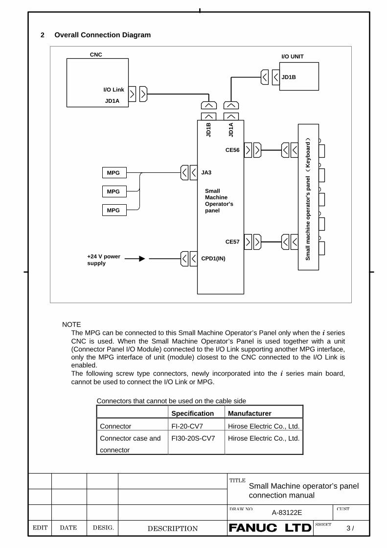
2 Overall Connection Diagram
NOTEThe MPG can be connected to this Small Machine Operator’s Panel only when the i seriesCNC is used. When the Small Machine Operator’s Panel is used together with a unit(Connector Panel I/O Module) connected to the I/O Link supporting another MPG interface,only the MPG interface of unit (module) closest to the CNC connected to the I/O Link isenabled.The following screw type connectors, newly incorporated into the i series main board,cannot be used to connect the I/O Link or MPG.
CNC
I/O Link
JD1A
CPD1(IN)
CE56
+24 V powersupply
CE57
Sm
all m
ach
ine
op
erat
or'
s p
anel
(K
eyb
oar
d)
SmallMachineOperator’spanel
JD1B
JD1A
JD1B
I/O UNIT
JA3MPG
MPG
MPG
Connectors that cannot be used on the cable side
Specification Manufacturer
Connector FI-20-CV7 Hirose Electric Co., Ltd.
Connector case and
connector
FI30-20S-CV7 Hirose Electric Co., Ltd.
EDIT DATE DESIG.
Small Machine operator’s panelconnection manual
TITLE
DESCRIPTION
DRAW.NO. A-83122E
SHEET
CUST
4 /
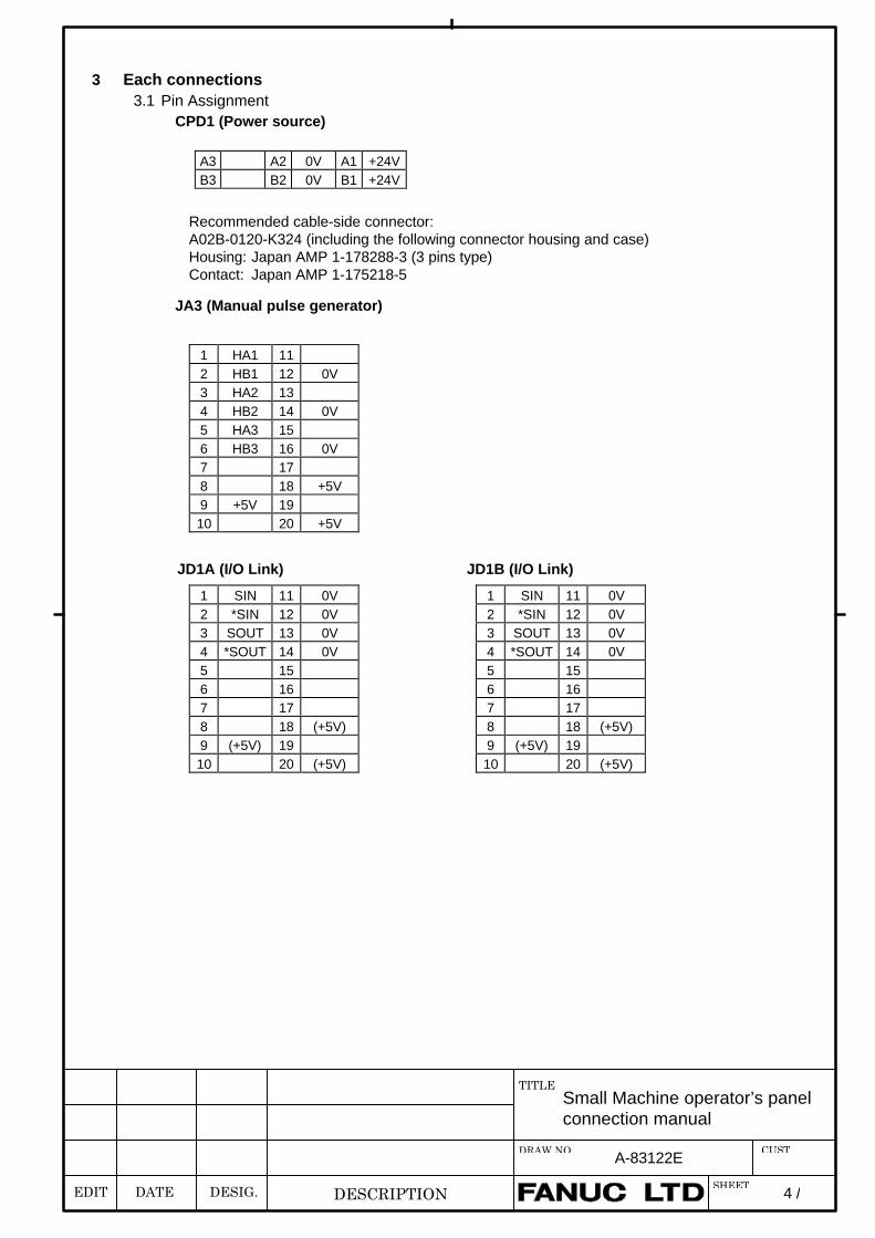
3 Each connections3.1 Pin Assignment
CPD1 (Power source)
JA3 (Manual pulse generator)
JD1A (I/O Link) JD1B (I/O Link)
A3 A2 0V A1 +24VB3 B2 0V B1 +24V
1 HA1 112 HB1 12 0V3 HA2 134 HB2 14 0V5 HA3 156 HB3 16 0V7 178 18 +5V9 +5V 1910 20 +5V
1 SIN 11 0V2 *SIN 12 0V3 SOUT 13 0V4 *SOUT 14 0V5 156 167 178 18 (+5V)9 (+5V) 1910 20 (+5V)
1 SIN 11 0V2 *SIN 12 0V3 SOUT 13 0V4 *SOUT 14 0V5 156 167 178 18 (+5V)9 (+5V) 1910 20 (+5V)
Recommended cable-side connector:A02B-0120-K324 (including the following connector housing and case)Housing: Japan AMP 1-178288-3 (3 pins type)Contact: Japan AMP 1-175218-5
EDIT DATE DESIG.
Small Machine operator’s panelconnection manual
TITLE
DESCRIPTION
DRAW.NO. A-83122E
SHEET
CUST
5 /
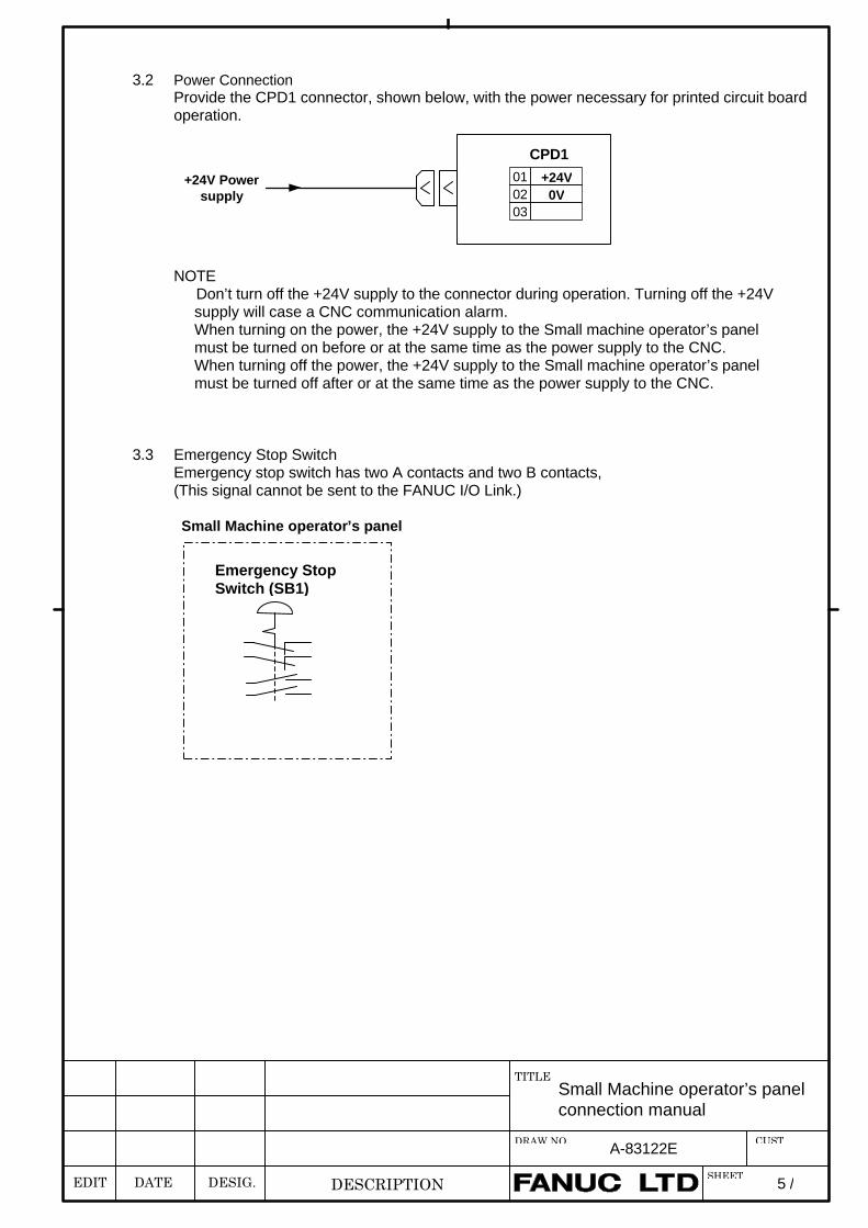
3.2 Power ConnectionProvide the CPD1 connector, shown below, with the power necessary for printed circuit boardoperation.
NOTEDon’t turn off the +24V supply to the connector during operation. Turning off the +24Vsupply will case a CNC communication alarm.When turning on the power, the +24V supply to the Small machine operator’s panelmust be turned on before or at the same time as the power supply to the CNC.When turning off the power, the +24V supply to the Small machine operator’s panelmust be turned off after or at the same time as the power supply to the CNC.
3.3 Emergency Stop SwitchEmergency stop switch has two A contacts and two B contacts,(This signal cannot be sent to the FANUC I/O Link.)
Small Machine operator’s panel
01 +24V02 0V03
CPD1
+24V Powersupply
Emergency StopSwitch (SB1)
EDIT DATE DESIG.
Small Machine operator’s panelconnection manual
TITLE
DESCRIPTION
DRAW.NO. A-83122E
SHEET
CUST
6 /
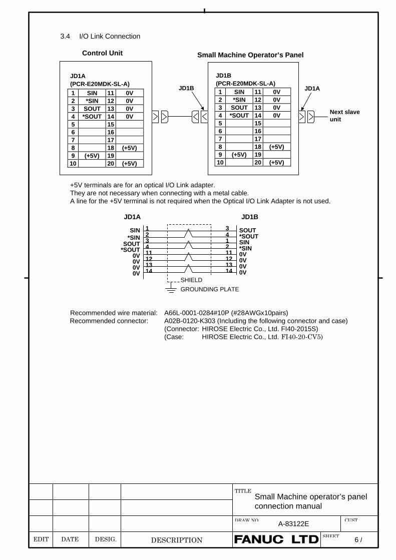
3.4 I/O Link Connection
+5V terminals are for an optical I/O Link adapter.They are not necessary when connecting with a metal cable.A line for the +5V terminal is not required when the Optical I/O Link Adapter is not used.
JD1A JD1B
Recommended wire material: A66L-0001-0284#10P (#28AWGx10pairs)Recommended connector: A02B-0120-K303 (Including the following connector and case)
(Connector: HIROSE Electric Co., Ltd. FI40-2015S)(Case: HIROSE Electric Co., Ltd. FI40-20-CV5)
1 SIN 11 0V2 *SIN 12 0V3 SOUT 13 0V4 *SOUT 14 0V5 156 167 178 18 (+5V)9 (+5V) 19
10 20 (+5V)
1 SIN 11 0V2 *SIN 12 0V3 SOUT 13 0V4 *SOUT 14 0V5 156 167 178 18 (+5V)9 (+5V) 19
10 20 (+5V)
JD1A(PCR-E20MDK-SL-A)
JD1B(PCR-E20MDK-SL-A)
Next slaveunit
JD1B JD1A
Control Unit Small Machine Operator’s Panel
SHIELD
GROUNDING PLATE
SIN*SIN
SOUT*SOUT
0V0V0V0V
123411121314
SOUT*SOUTSIN*SIN0V0V0V0V
341211121314
EDIT DATE DESIG.
Small Machine operator’s panelconnection manual
TITLE
DESCRIPTION
DRAW.NO. A-83122E
SHEET
CUST
7 /
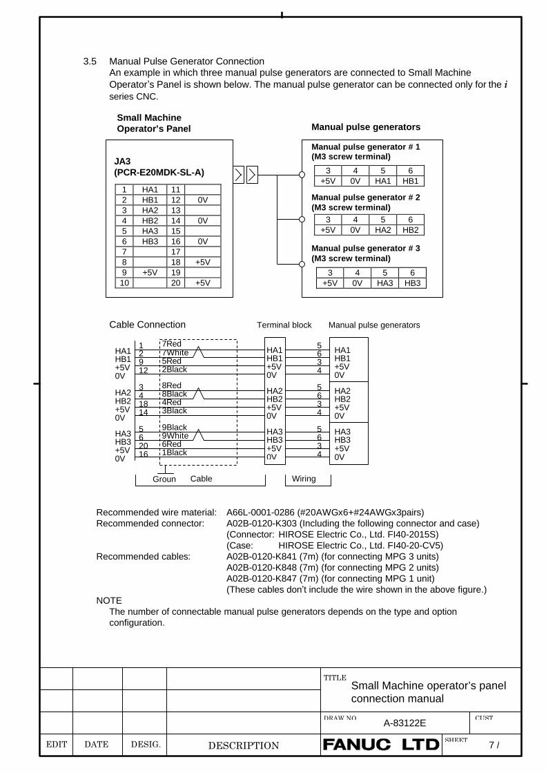
3.5 Manual Pulse Generator ConnectionAn example in which three manual pulse generators are connected to Small MachineOperator’s Panel is shown below. The manual pulse generator can be connected only for the iseries CNC.
Cable Connection Terminal block Manual pulse generators
Recommended wire material: A66L-0001-0286 (#20AWGx6+#24AWGx3pairs)Recommended connector: A02B-0120-K303 (Including the following connector and case)
(Connector: HIROSE Electric Co., Ltd. FI40-2015S)(Case: HIROSE Electric Co., Ltd. FI40-20-CV5)
Recommended cables: A02B-0120-K841 (7m) (for connecting MPG 3 units)A02B-0120-K848 (7m) (for connecting MPG 2 units)A02B-0120-K847 (7m) (for connecting MPG 1 unit)(These cables don’t include the wire shown in the above figure.)
NOTEThe number of connectable manual pulse generators depends on the type and optionconfiguration.
1 HA1 112 HB1 12 0V3 HA2 134 HB2 14 0V5 HA3 156 HB3 16 0V7 178 18 +5V9 +5V 1910 20 +5V
3 4 5 6+5V 0V HA1 HB1
3 4 5 6+5V 0V HA2 HB2
3 4 5 6+5V 0V HA3 HB3
Small MachineOperator’s Panel
JA3(PCR-E20MDK-SL-A)
Manual pulse generator # 1(M3 screw terminal)
Manual pulse generator # 2(M3 screw terminal)
Manual pulse generator # 3(M3 screw terminal)
Manual pulse generators
5634
5634
5634
HA1HB1+5V0V
HA2HB2+5V0V
HA3HB3+5V0V
12912
341814
562016
HA1HB1+5V0V
HA2HB2+5V0V
HA3HB3+5V0V
7Red7White5Red2Black
8Red8Black4Red3Black
9Black9White6Red1Black
HA1HB1+5V0V
HA2HB2+5V0V
HA3HB3+5V0V
Cable WiringGround
EDIT DATE DESIG.
Small Machine operator’s panelconnection manual
TITLE
DESCRIPTION
DRAW.NO. A-83122E
SHEET
CUST
8 /
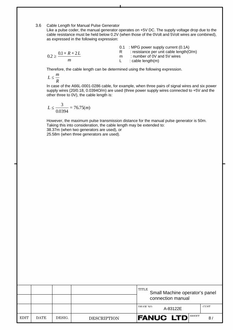
3.6 Cable Length for Manual Pulse GeneratorLike a pulse coder, the manual generator operates on +5V DC. The supply voltage drop due to thecable resistance must be held below 0.2V (when those of the 0Volt and 5Volt wires are combined),as expressed in the following expression:
0 201 2
..
≥× ×R L
m
Therefore, the cable length can be determined using the following expression.
LmR
≤
In case of the A66L-0001-0286 cable, for example, when three pairs of signal wires and six powersupply wires (20/0.18, 0.0394O/m) are used (three power supply wires connected to +5V and theother three to 0V), the cable length is:
L m≤ =3
0 039476 75
.. ( )
However, the maximum pulse transmission distance for the manual pulse generator is 50m.Taking this into consideration, the cable length may be extended to:38.37m (when two generators are used), or25.58m (when three generators are used).
0.1 : MPG power supply current (0.1A)R : resistance per unit cable length(O/m)m : number of 0V and 5V wiresL : cable length(m)
EDIT DATE DESIG.
Small Machine operator’s panelconnection manual
TITLE
DESCRIPTION
DRAW.NO. A-83122E
SHEET
CUST
9 /
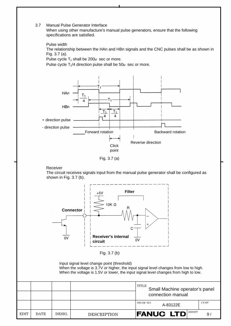
3.7 Manual Pulse Generator InterfaceWhen using other manufacture’s manual pulse generators, ensure that the followingspecifications are satisfied.
Pulse widthThe relationship between the HAn and HBn signals and the CNC pulses shall be as shown inFig. 3.7 (a).Pulse cycle T1 shall be 200μsec or more.Pulse cycle T1/4 direction pulse shall be 50μsec or more.
Fig. 3.7 (a)
ReceiverThe circuit receives signals input from the manual pulse generator shall be configured asshown in Fig. 3.7 (b).
Fig. 3.7 (b)
Clickpoint
Reverse direction
Forward rotation Backward rotation
+ direction pulse
- direction pulse
Filter
Connector
Receiver’s internalcircuit
Input signal level change point (threshold)When the voltage is 3.7V or higher, the input signal level changes from low to high.When the voltage is 1.5V or lower, the input signal level changes from high to low.
EDIT DATE DESIG.
Small Machine operator’s panelconnection manual
TITLE
DESCRIPTION
DRAW.NO. A-83122E
SHEET
CUST
10 /
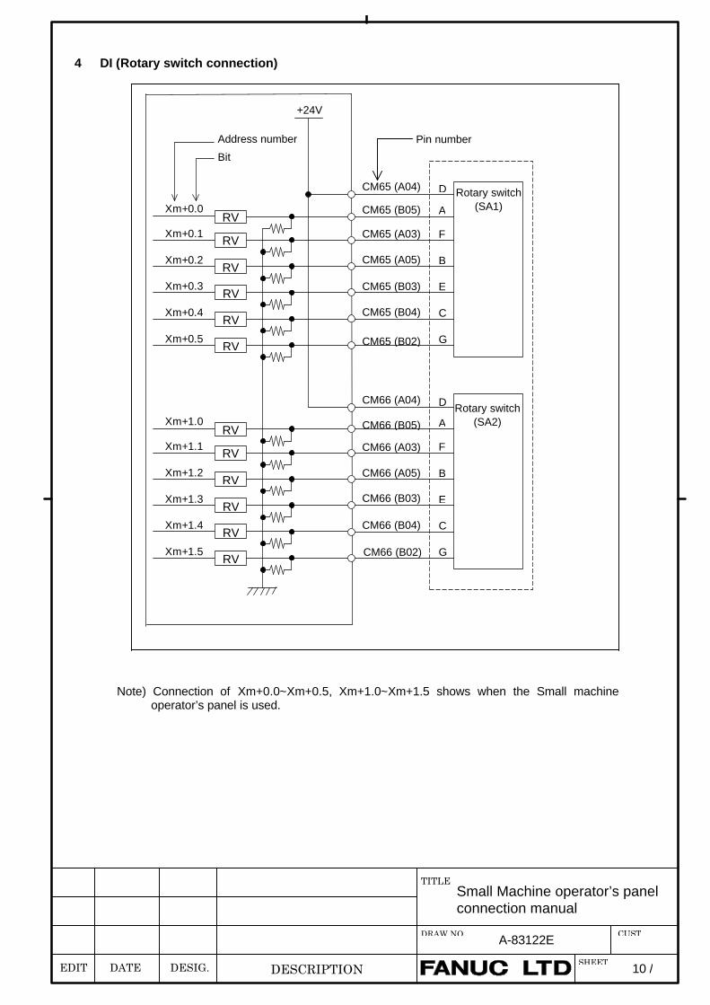
4 DI (Rotary switch connection)
Note) Connection of Xm+0.0~Xm+0.5, Xm+1.0~Xm+1.5 shows when the Small machineoperator’s panel is used.
+24V
Pin numberAddress number
Bit
CM65 (A04) D Rotary switch(SA1)
RVXm+0.5 G
Xm+0.0RV
ACM65 (B05)
RVXm+0.1 FCM65 (A03)
RVXm+0.2 BCM65 (A05)
RVXm+0.3 ECM65 (B03)
RVXm+0.4 CCM65 (B04)
RVXm+1.5 G
Xm+1.0RV
ACM66 (B05)
RVXm+1.1 FCM66 (A03)
RVXm+1.2 BCM66 (A05)
RVXm+1.3 ECM66 (B03)
RVXm+1.4 CCM66 (B04)
CM66 (A04) D
CM65 (B02)
CM66 (B02)
Rotary switch(SA2)
EDIT DATE DESIG.
Small Machine operator’s panelconnection manual
TITLE
DESCRIPTION
DRAW.NO. A-83122E
SHEET
CUST
11 /
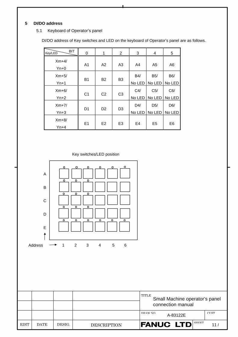
5 DI/DO address
5.1 Keyboard of Operator’s panel
DI/DO address of Key switches and LED on the keyboard of Operator’s panel are as follows.
0 1 2 3 4 5
Xm+4/
Yn+0A1 A2 A3 A4 A5 A6
Xm+5/
Yn+1B1 B2 B3
B4/
No LED
B5/
No LED
B6/
No LED
Xm+6/
Yn+2C1 C2 C3
C4/
No LED
C5/
No LED
C6/
No LED
Xm+7/
Yn+3D1 D2 D3
D4/
No LED
D5/
No LED
D6/
No LED
Xm+8/
Yn+4E1 E2 E3 E4 E5 E6
A
B
C
D
E
Key switches/LED position
Address 1 2 3 4 5 6
BITKey/LED
EDIT DATE DESIG.
Small Machine operator’s panelconnection manual
TITLE
DESCRIPTION
DRAW.NO. A-83122E
SHEET
CUST
12 /
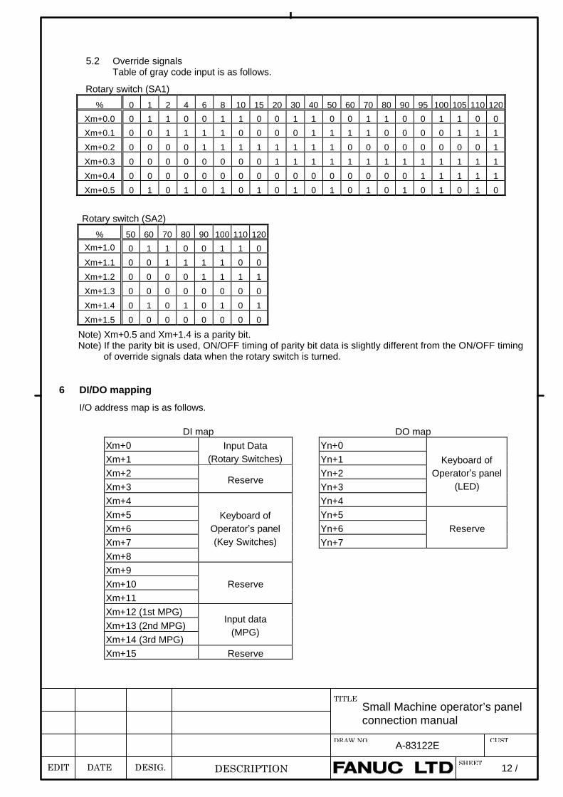
5.2 Override signalsTable of gray code input is as follows.
Rotary switch (SA1)
% 0 1 2 4 6 8 10 15 20 30 40 50 60 70 80 90 95 100 105 110 120
Xm+0.0 0 1 1 0 0 1 1 0 0 1 1 0 0 1 1 0 0 1 1 0 0
Xm+0.1 0 0 1 1 1 1 0 0 0 0 1 1 1 1 0 0 0 0 1 1 1
Xm+0.2 0 0 0 0 1 1 1 1 1 1 1 1 0 0 0 0 0 0 0 0 1
Xm+0.3 0 0 0 0 0 0 0 0 1 1 1 1 1 1 1 1 1 1 1 1 1
Xm+0.4 0 0 0 0 0 0 0 0 0 0 0 0 0 0 0 0 1 1 1 1 1
Xm+0.5 0 1 0 1 0 1 0 1 0 1 0 1 0 1 0 1 0 1 0 1 0
Rotary switch (SA2)
% 50 60 70 80 90 100 110 120Xm+1.0 0 1 1 0 0 1 1 0
Xm+1.1 0 0 1 1 1 1 0 0
Xm+1.2 0 0 0 0 1 1 1 1
Xm+1.3 0 0 0 0 0 0 0 0
Xm+1.4 0 1 0 1 0 1 0 1
Xm+1.5 0 0 0 0 0 0 0 0
Note) Xm+0.5 and Xm+1.4 is a parity bit. Note) If the parity bit is used, ON/OFF timing of parity bit data is slightly different from the ON/OFF timing
of override signals data when the rotary switch is turned.
6 DI/DO mapping
I/O address map is as follows.
DI map DO mapXm+0 Yn+0Xm+1
Input Data(Rotary Switches) Yn+1
Xm+2 Yn+2Xm+3
ReserveYn+3
Xm+4 Yn+4
Keyboard ofOperator’s panel
(LED)
Xm+5 Yn+5Xm+6 Yn+6Xm+7 Yn+7
Reserve
Xm+8
Keyboard ofOperator’s panel(Key Switches)
Xm+9Xm+10Xm+11
Reserve
Xm+12 (1st MPG)Xm+13 (2nd MPG)Xm+14 (3rd MPG)
Input data(MPG)
Xm+15 Reserve
EDIT DATE DESIG.
Small Machine operator’s panelconnection manual
TITLE
DESCRIPTION
DRAW.NO. A-83122E
SHEET
CUST
13 /
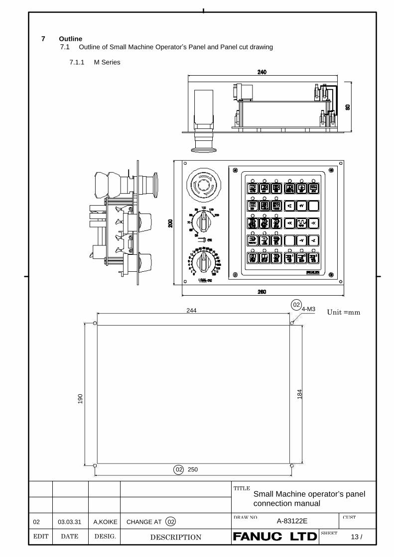
7 Outline7.1 Outline of Small Machine Operator’s Panel and Panel cut drawing
7.1.1 M Series
Unit =mm
02 03.03.31 A,KOIKE CHANGE AT 02
244
250
190 18
4
4-M3
02
02
EDIT DATE DESIG.
Small Machine operator’s panelconnection manual
TITLE
DESCRIPTION
DRAW.NO. A-83122E
SHEET
CUST
14 /
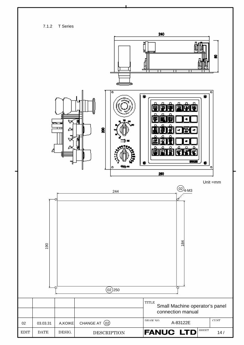
7.1.2 T Series
Unit =mm
02 03.03.31 A,KOIKE CHANGE AT 02
244
250
190 18
4
4-M3
02
02
EDIT DATE DESIG.
Small Machine operator’s panelconnection manual
TITLE
DESCRIPTION
DRAW.NO. A-83122E
SHEET
CUST
15 /
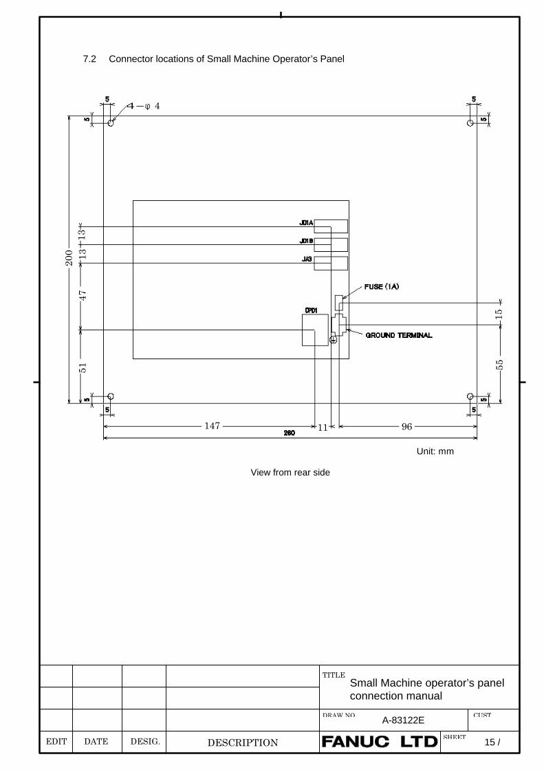
7.2 Connector locations of Small Machine Operator’s Panel
Unit: mm
View from rear side
4-φ4
1313
4751
200
1555
147 11 96
EDIT DATE DESIG.
Small Machine operator’s panelconnection manual
TITLE
DESCRIPTION
DRAW.NO. A-83122E
SHEET
CUST
16 /
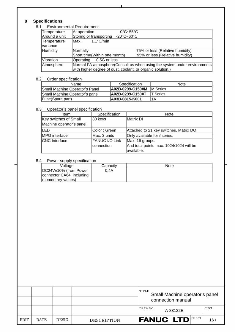
8 Specifications8.1 Environmental Requirement
TemperatureAround a unit
At operation 0°C~55°CStoring or transporting -20°C~60°C
Temperaturevariance
Max. 1.1°C/min
Humidity Normally 75% or less (Relative humidity)Short time(Within one month) 95% or less (Relative humidity)
Vibration Operating 0.5G or lessAtmosphere Normal FA atmosphere(Consult us when using the system under environments
with higher degree of dust, coolant, or organic solution.)
8.2 Order specificationName Specification Note
Small Machine Operator’s Panel A02B-0299-C150#M M SeriesSmall Machine Operator’s panel A02B-0299-C150#T T SeriesFuse(Spare part) A03B-0815-K001 1A
8.3 Operator’s panel specificationItem Specification Note
Key switches of SmallMachine operator’s panel
30 keys Matrix DI
LED Color : Green Attached to 21 key switches, Matrix DOMPG interface Max. 3 units Only available for i series.CNC Interface FANUC I/O Link
connectionMax. 16 groups.And total points max. 1024/1024 will beavailable.
8.4 Power supply specificationVoltage Capacity Note
DC24V±10% (from Powerconnector CA64, includingmomentary values)
0.4A
EDIT DATE DESIG.
Small Machine operator’s panelconnection manual
TITLE
DESCRIPTION
DRAW.NO. A-83122E
SHEET
CUST
17 /
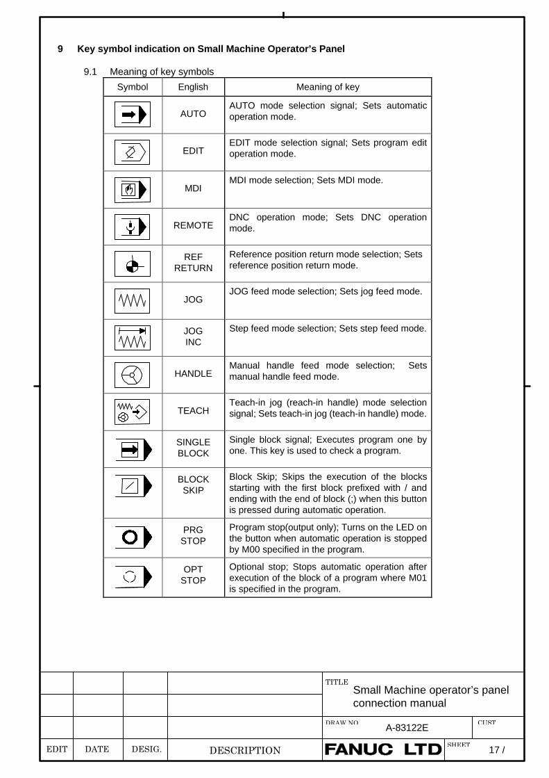
9 Key symbol indication on Small Machine Operator’s Panel
9.1 Meaning of key symbols
Symbol English Meaning of key
AUTOAUTO mode selection signal; Sets automaticoperation mode.
EDITEDIT mode selection signal; Sets program editoperation mode.
MDIMDI mode selection; Sets MDI mode.
REMOTEDNC operation mode; Sets DNC operationmode.
REFRETURN
Reference position return mode selection; Setsreference position return mode.
JOGJOG feed mode selection; Sets jog feed mode.
JOGINC
Step feed mode selection; Sets step feed mode.
HANDLEManual handle feed mode selection; Setsmanual handle feed mode.
TEACHTeach-in jog (reach-in handle) mode selectionsignal; Sets teach-in jog (teach-in handle) mode.
SINGLEBLOCK
Single block signal; Executes program one byone. This key is used to check a program.
BLOCKSKIP
Block Skip; Skips the execution of the blocksstarting with the first block prefixed with / andending with the end of block (;) when this buttonis pressed during automatic operation.
PRGSTOP
Program stop(output only); Turns on the LED onthe button when automatic operation is stoppedby M00 specified in the program.
OPTSTOP
Optional stop; Stops automatic operation afterexecution of the block of a program where M01is specified in the program.
EDIT DATE DESIG.
Small Machine operator’s panelconnection manual
TITLE
DESCRIPTION
DRAW.NO. A-83122E
SHEET
CUST
18 /
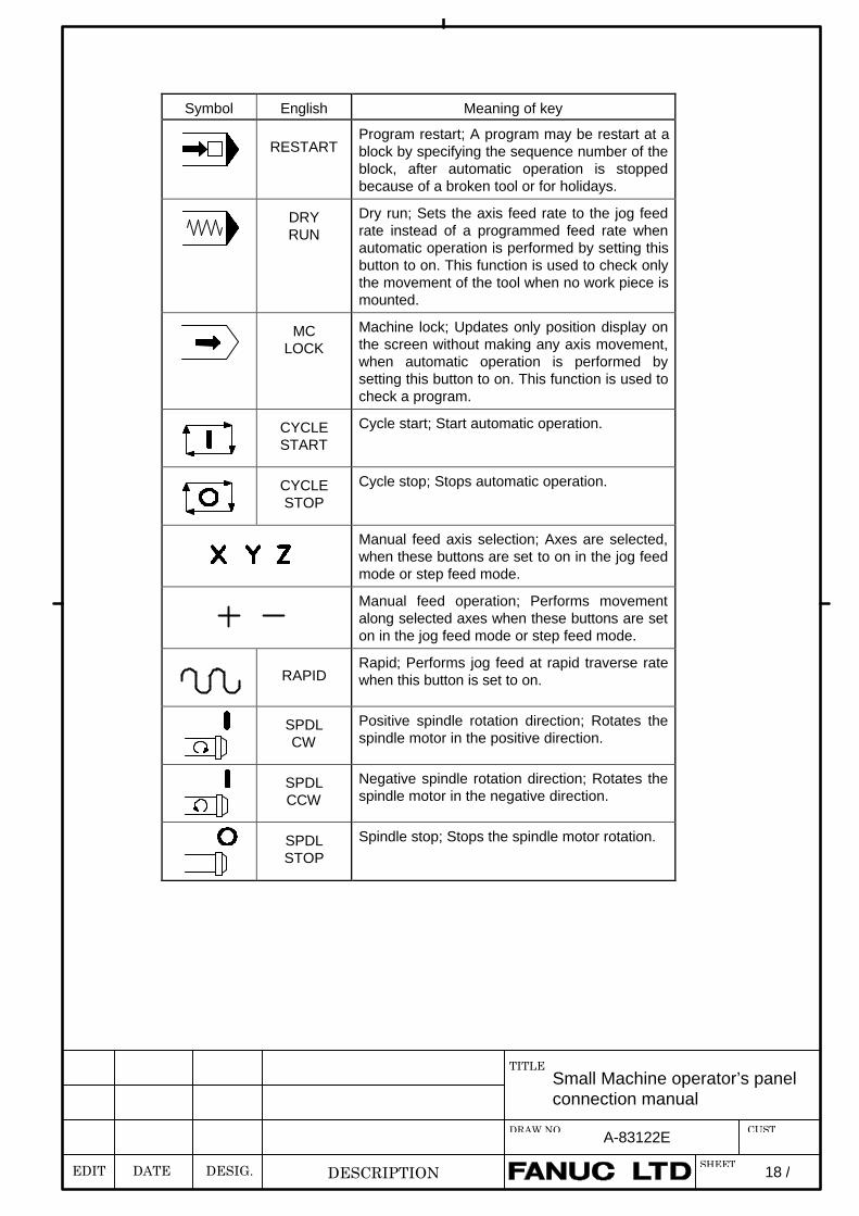
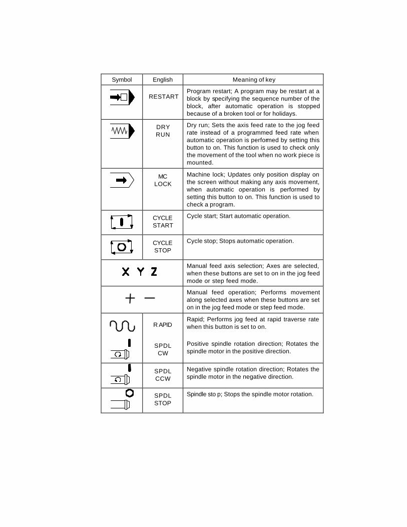
Symbol English Meaning of key
RESTARTProgram restart; A program may be restart at ablock by specifying the sequence number of theblock, after automatic operation is stoppedbecause of a broken tool or for holidays.
DRYRUN
Dry run; Sets the axis feed rate to the jog feedrate instead of a programmed feed rate whenautomatic operation is performed by setting thisbutton to on. This function is used to check onlythe movement of the tool when no work piece ismounted.
MCLOCK
Machine lock; Updates only position display onthe screen without making any axis movement,when automatic operation is performed bysetting this button to on. This function is used tocheck a program.
CYCLESTART
Cycle start; Start automatic operation.
CYCLESTOP
Cycle stop; Stops automatic operation.
Manual feed axis selection; Axes are selected,when these buttons are set to on in the jog feedmode or step feed mode.
Manual feed operation; Performs movementalong selected axes when these buttons are seton in the jog feed mode or step feed mode.
RAPIDRapid; Performs jog feed at rapid traverse ratewhen this button is set to on.
SPDLCW
Positive spindle rotation direction; Rotates thespindle motor in the positive direction.
SPDLCCW
Negative spindle rotation direction; Rotates thespindle motor in the negative direction.
SPDLSTOP
Spindle stop; Stops the spindle motor rotation.
EDIT DATE DESIG.
Small Machine operator’s panelconnection manual
TITLE
DESCRIPTION
DRAW.NO. A-83122E
SHEET
CUST
19 /
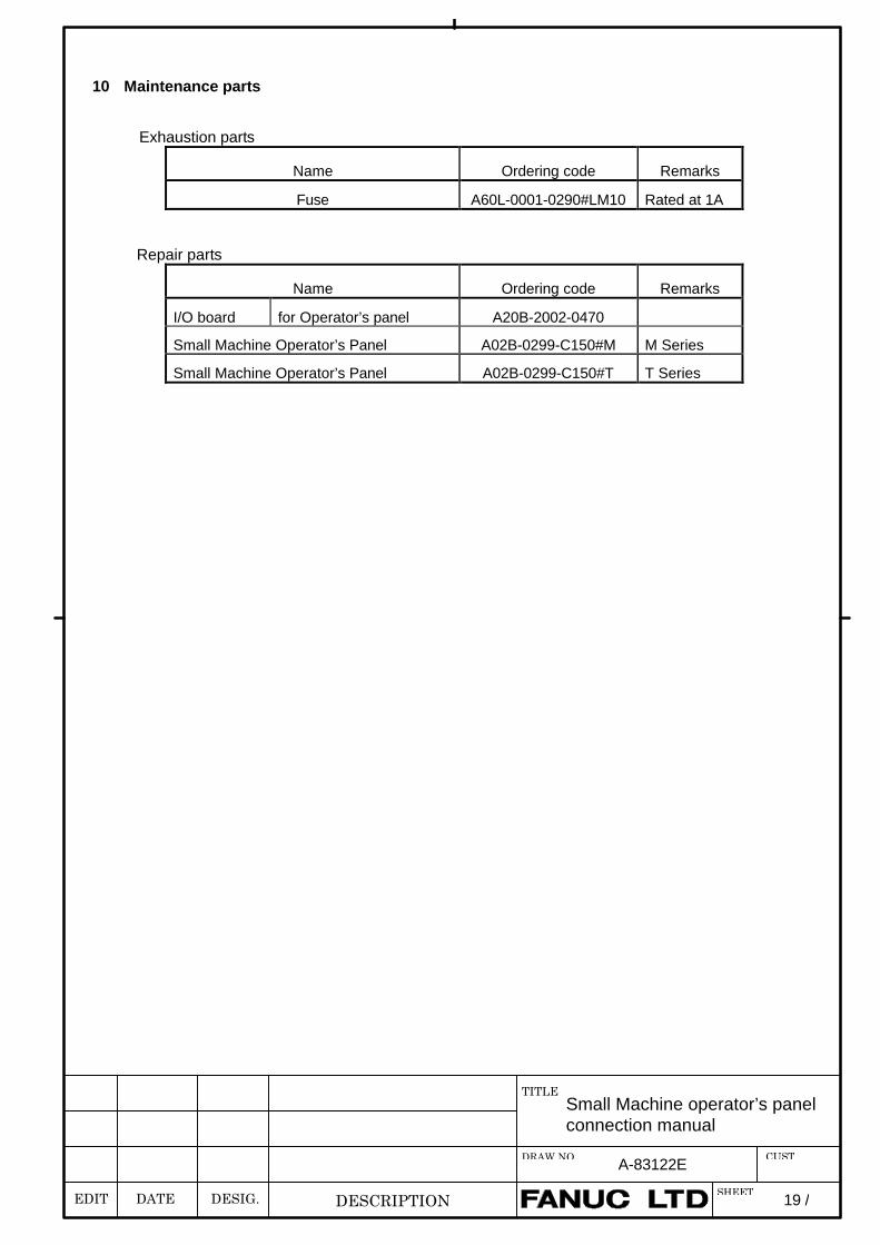
10 Maintenance parts
Exhaustion parts
Name Ordering code Remarks
Fuse A60L-0001-0290#LM10 Rated at 1A
Repair parts
Name Ordering code Remarks
I/O board for Operator’s panel A20B-2002-0470
Small Machine Operator’s Panel A02B-0299-C150#M M Series
Small Machine Operator’s Panel A02B-0299-C150#T T Series
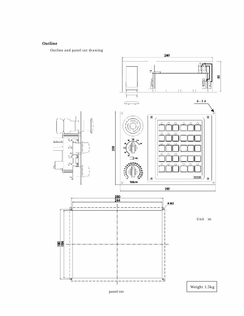
Outline
Outline and panel cut drawing
Unit :m
Weight 1.5kg panel cut
4 - φ 4
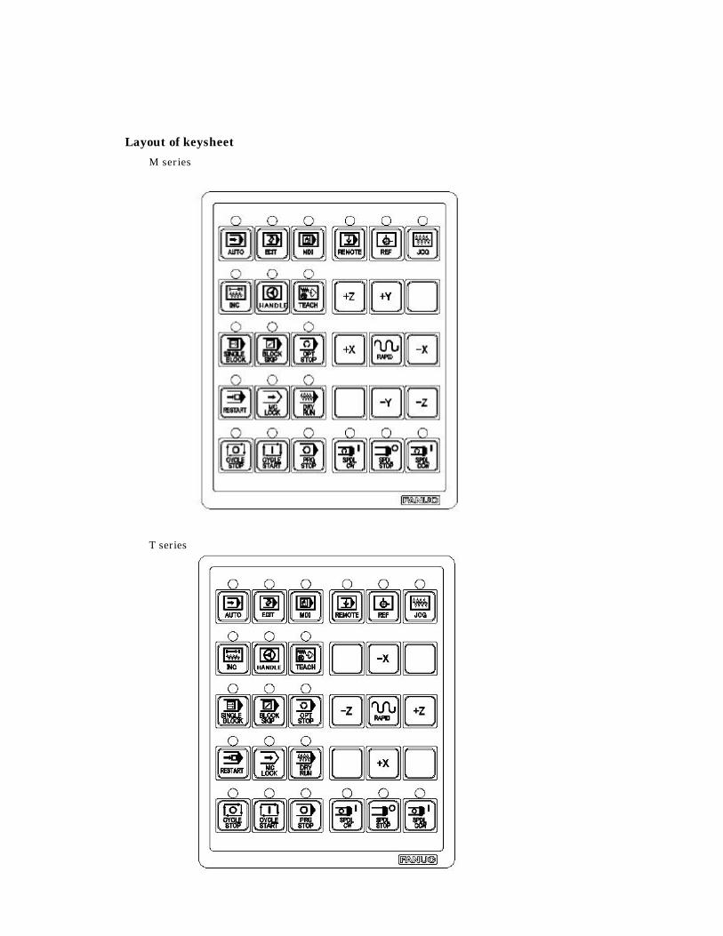
Layout of keysheet
M series
T series
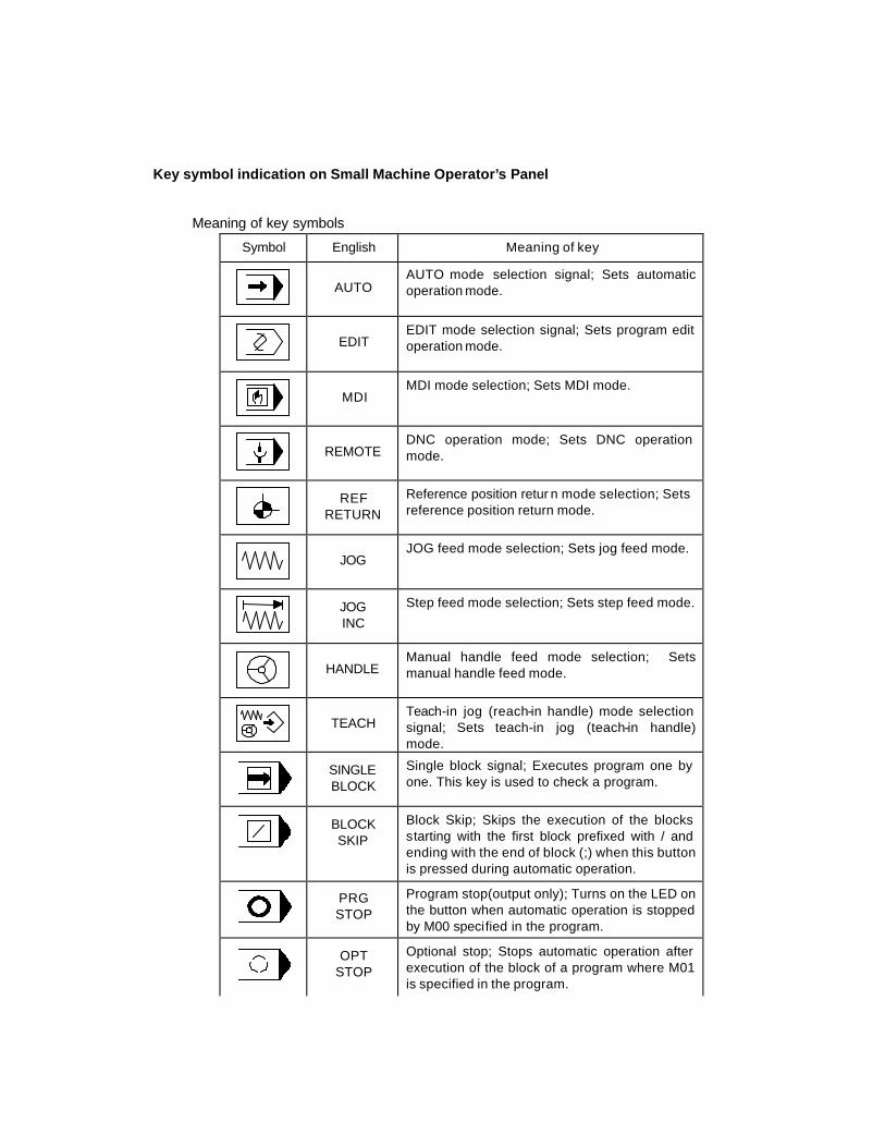
Key symbol indication on Small Machine Operator’s Panel
Meaning of key symbols
Symbol English Meaning of key
AUTO
AUTO mode selection signal; Sets automatic operation mode.
EDIT
EDIT mode selection signal; Sets program edit operation mode.
MDI
MDI mode selection; Sets MDI mode.
REMOTE
DNC operation mode; Sets DNC operation mode.
REF
RETURN
Reference position retur n mode selection; Sets reference position return mode.
JOG
JOG feed mode selection; Sets jog feed mode.
JOG INC
Step feed mode selection; Sets step feed mode.
HANDLE
Manual handle feed mode selection; Sets manual handle feed mode.
TEACH
Teach-in jog (reach-in handle) mode selection signal; Sets teach-in jog (teach-in handle) mode.
SINGLE BLOCK
Single block signal; Executes program one by one. This key is used to check a program.
BLOCK SKIP
Block Skip; Skips the execution of the blocks starting with the first block prefixed with / and ending with the end of block (;) when this button is pressed during automatic operation.
PRG STOP
Program stop(output only); Turns on the LED on the button when automatic operation is stopped by M00 specified in the program.
OPT
STOP
Optional stop; Stops automatic operation after execution of the block of a program where M01 is specified in the program.
Symbol English Meaning of key
RESTART Program restart; A program may be restart at a block by specifying the sequence number of the block, after automatic operation is stopped because of a broken tool or for holidays.
DRY RUN
Dry run; Sets the axis feed rate to the jog feed rate instead of a programmed feed rate when automatic operation is performed by setting this button to on. This function is used to check only the movement of the tool when no work piece is mounted.
MC
LOCK
Machine lock; Updates only position display on the screen without making any axis movement, when automatic operation is performed by setting this button to on. This function is used to check a program.
CYCLE START
Cycle start; Start automatic operation.
CYCLE STOP
Cycle stop; Stops automatic operation.
Manual feed axis selection; Axes are selected, when these buttons are set to on in the jog feed mode or step feed mode.
Manual feed operation; Performs movement along selected axes when these buttons are set on in the jog feed mode or step feed mode.
R APID
Rapid; Performs jog feed at rapid traverse rate when this button is set to on.
SPDL CW
Positive spindle rotation direction; Rotates the spindle motor in the positive direction.
SPDL CCW
Negative spindle rotation direction; Rotates the spindle motor in the negative direction.
SPDL STOP
Spindle sto p; Stops the spindle motor rotation.