Embed Size (px)
Citation preview

SRAD: A SEMANTIC RAPID METHOD FOR
SOFTWARE DEVELOPMENT
Morteza Noroozi, Shima Saedi, Mohsen Taherian
[email protected], [email protected], [email protected]
Abstract- Using Semantic Web (SW) technologies in Software Engineering (SE) is one way of
overcoming current SE problems which are related to the software production and
maintenance. In this article, we have proposed a new semantic method for rapid software
development, namely SRAD. From SRAD point of view, static and dynamic model of software
are described in domain ontology and application ontology, respectively. The domain ontology
can be a strong substitute for data model and the application ontology contains formal
description and implementation of software functionalities. We have also proposed a new
method for implementing the functionalities in the application ontology by using the SW
technologies. To execute the software functionalities, any Java compatible rule engine like Jess
can be used, but for efficiency reasons, we have developed a Running Engine (RE) that supports
all types of SWRL atoms. By using SRAD method, opposed to the current development
methods that try to generate code from models, we can produce a formal runnable model of
software which encompasses both business logic and program control logic. The SRAD
runnable models can facilitate the software maintenance and gain a high level of abstraction in
the software production.
Keywords- Software development, Semantic Web, ontology driven development, ontology
based development, runnable models.
1 Introduction The Semantic Web (SW) is the next generation of the current web which is a vision of
information that can be readily interpreted by machines [1], so machines need to understand
the meaning of information on the web with the aid of some additional formal descriptions.
Basically, adding some formal descriptions to existing information on web pages are generally
based on using some special formal models which are called ontologies. According to
Grubber [2], “An ontology is a formal, explicit specification of a shared conceptualization”. In
simple terms, an ontology represents existing concepts, objects and relations in a domain as
sets of classes, instances of classes and properties. The W3C standards and languages for the
SW include the Resource Description Framework (RDF) [3], RDF-Schema [4], the Web Ontology
Language (OWL) [5], and the Semantic Web Rule Language (SWRL) [6]. RDF is a general purpose
language for describing and representing information, and particularly metadata about web
resources. RDF-Schema extends RDF vocabulary for defining classes, properties, and hierarchies
thereof, but it has no construct for defining properties restrictions, set operations and totally
complex classes. OWL is a complete ontology language that fully covers all shortages of its
predecessors. OWL 2 [7] is the newest language which is currently defined by a set of W3C
recommendations. OWL 2 extends OWL by providing some new constructs to amplify OWL
expressiveness power and some others as syntactic sugar to make some common patterns
easier to write. SWRL extends the OWL axioms, so that it’s possible to define rules in the web
ontology for deducing new facts from existing ones.
Software development is a complex process, which involves software engineers in gathering,
production and management of large amount of information, including application or domain
specific jargon which the software engineers often have to learn for each project they get
assigned to [8]. Software processes often have iterative nature, so during each iteration of a
process activity, the software engineers should have a satisfactory understanding of previous
iterations of the activity. Large software projects can be more complicated because they have a
lot of requirements and design documents and specifications, UML models, and codes. The
software understanding is a key point for software maintenance, too. The maintenance team
should first gain a deep and clear understanding of software project through its documents,
models and codes. Rapid Application Development (RAD) [10] methods which concentrate on
rapid software production and delivery, try to reduce the complexities of software
development process and eventually decrease the software production time and costs. But
sometimes RAD methods could inversely cause the costs to increase. It’s because there is
almost an inverse relationship between the software production costs and the software
maintenance costs.
Using the SW technologies in Software Engineering (SE) is one way of overcoming current SE
problems which recently has gained many proponents. In this article we have proposed the
Semantic Rapid Application Development (SRAD) method. The SRAD is a new software
development method which simultaneously inherits some advantages from RAD methods and
ontology driven development methods .In the SRAD method, static and dynamic model of
software are described in Domain Ontology (DO) and Application Ontology (AO), respectively.
The DO contains a formal description of all existing concepts and objects in the domain as well
as their relationships. The AO contains a formal description and implementation of software
functionalities. We can organize these functionalities in the AO hierarchically, and then
implement each of them by using a list of SWRL rules. To execute such functionalities we can
use a Java compatible rule engine like Jess [12], but for efficiency reasons, we have developed a
Running Engine (RE) that supports all type of SWRL atoms1.
1 RE is available at: https://sites.google.com/site/sradproject/

The rest of this paper is organized as follows: Section 2 surveys and categorizes some important
approaches which try to bring together the SW technologies and SE. Section 3 explains our
purposed method for implementing functions in ontologies. Section 4 compares the SRAD
viewpoint with the object-oriented and the structured viewpoints. Section 5 presents the SRAD
model and discusses about its phases and activities. Section 6 evaluates the SRAD and discusses
about its advantages and finally Section 7 covers suggestions and conclusions.
2 Related Works The idea of using SW technologies in SE has gotten serious consideration ever since 2005 and
researchers have currently proposed a variety of approaches to this idea. Some reports claim
that empowering the software development with the SW technologies has noticeable
advantages, like reusability, extensibility of data models, improvements in data quality, and
discovery and automated execution of workflows [13][14][15]. The Semantic Web Best Practice
and Deployment Working Group (SWBPD) in W3C has started a Software Engineering Task
Force (SETF) to investigate potential benefits of bringing SE and the SW technologies
together [16][17].
We have categorized all related approaches into two groups: 1. Ontology Enabled Software
Development (OESD) 2. Otology Driven Software Development (ODSD). OESD approaches use
SW components, especially ontologies, as auxiliary facilities in aid of traditional and well-known
SE processes. In fact, OESD approaches try to help software engineers to successfully fulfill
various Software process activities (e.g. requirement engineering, analysis, architecture design,
implementation, test, quality assurance and maintenance) more efficient. Table 1 summarizes a
variety of approaches that suggest using the SW technologies in SE knowledge engineering,
Software process and different activities within software process.
Domain Objectives
SE knowledge engineering To define SE discipline terms and concepts explicitly in SE ontology with the aim of resolving some problems like miscommunication between developers, multi-site software development, and also to clarify the boundaries of SE with other disciplines [18][19][20][21][22][23].
Software process To define software activities, process phases and different process models formally in process ontology with the aim of settling any misunderstanding about software processes concepts and selecting an appropriate paradigm [24][25][26][27].
Requirements engineering To capture software requirements in ontologies and apply reasoners to check consistency and completeness. Also these ontologies can be used to bridge the gap between developers and business experts [28][29][13].
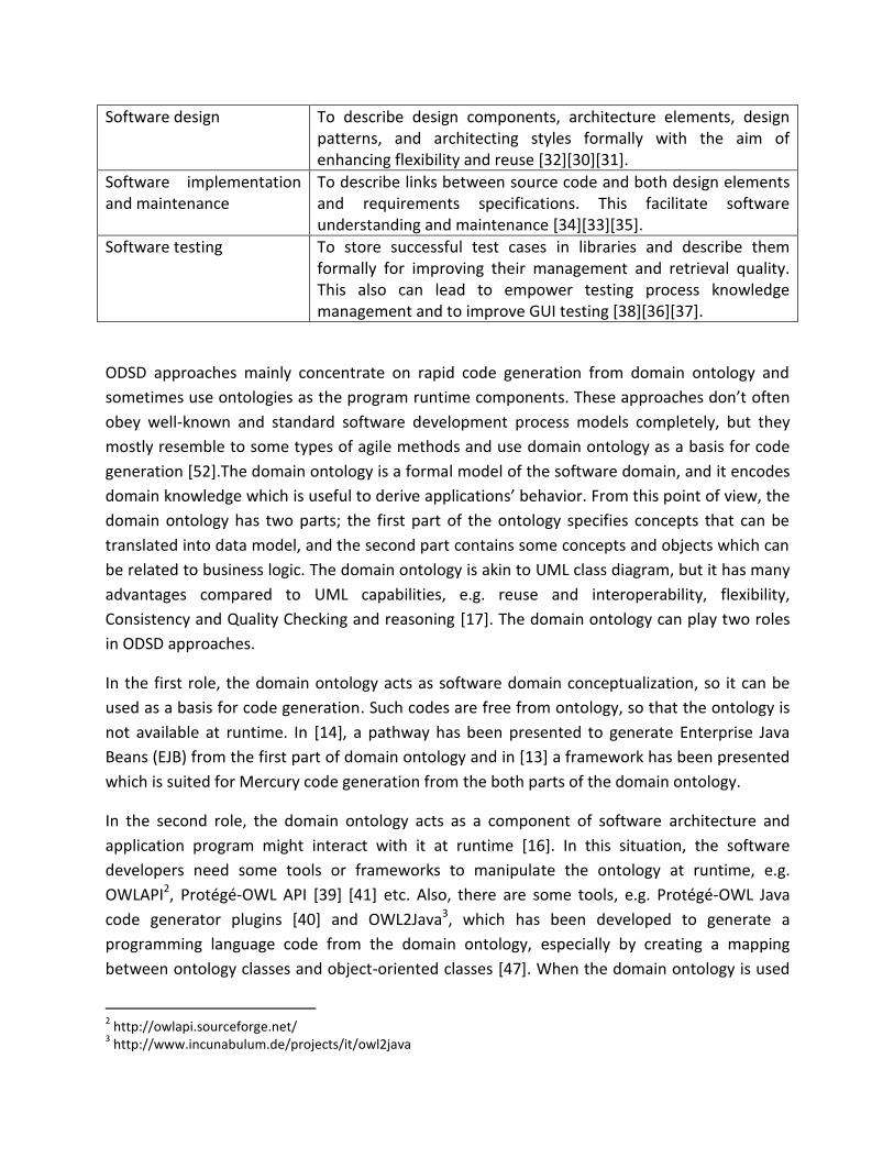
Software design To describe design components, architecture elements, design patterns, and architecting styles formally with the aim of enhancing flexibility and reuse [32][30][31].
Software implementation and maintenance
To describe links between source code and both design elements and requirements specifications. This facilitate software understanding and maintenance [34][33][35].
Software testing To store successful test cases in libraries and describe them formally for improving their management and retrieval quality. This also can lead to empower testing process knowledge management and to improve GUI testing [38][36][37].
ODSD approaches mainly concentrate on rapid code generation from domain ontology and
sometimes use ontologies as the program runtime components. These approaches don’t often
obey well-known and standard software development process models completely, but they
mostly resemble to some types of agile methods and use domain ontology as a basis for code
generation [52].The domain ontology is a formal model of the software domain, and it encodes
domain knowledge which is useful to derive applications’ behavior. From this point of view, the
domain ontology has two parts; the first part of the ontology specifies concepts that can be
translated into data model, and the second part contains some concepts and objects which can
be related to business logic. The domain ontology is akin to UML class diagram, but it has many
advantages compared to UML capabilities, e.g. reuse and interoperability, flexibility,
Consistency and Quality Checking and reasoning [17]. The domain ontology can play two roles
in ODSD approaches.
In the first role, the domain ontology acts as software domain conceptualization, so it can be
used as a basis for code generation. Such codes are free from ontology, so that the ontology is
not available at runtime. In [14], a pathway has been presented to generate Enterprise Java
Beans (EJB) from the first part of domain ontology and in [13] a framework has been presented
which is suited for Mercury code generation from the both parts of the domain ontology.
In the second role, the domain ontology acts as a component of software architecture and
application program might interact with it at runtime [16]. In this situation, the software
developers need some tools or frameworks to manipulate the ontology at runtime, e.g.
OWLAPI2, Protégé-OWL API [39] [41] etc. Also, there are some tools, e.g. Protégé-OWL Java
code generator plugins [40] and OWL2Java3, which has been developed to generate a
programming language code from the domain ontology, especially by creating a mapping
between ontology classes and object-oriented classes [47]. When the domain ontology is used
2 http://owlapi.sourceforge.net/
3 http://www.incunabulum.de/projects/it/owl2java
in the second role, all system data is captured in the ABox of the domain ontology as set of
instances, so the domain ontology can be very large. The TBox of the domain ontology contains
data model, and to some extent it can contain business logic.
Storing a big ontology, like the domain ontology in the second role, in a text file can cause
several serious efficiency and security problems. The relational databases can be used as a basis
for persistent storage of the ontologies. This facilitates rapid operations such as search and
retrieval over ontology elements and also utilizes the powerful capabilities of relational
Databases Management Systems (DBMS), such as transaction management, security, integrity
control etc. By putting a large ontology in a database we can profit from security and efficiency
of DBMS as well as semantic power of ontologies. There are several tools and frameworks to
store an ontology in a database [45][42][43][44].
Knublauch believes that using OWL and its tools for software development instead of similar
tools from UML world, has many advantages [46]. From his point of view, OWL and SWRL can
be used at runtime to do reasoning, or even to drive control logic of a software program, and
they also can be executable just like programming code. This means that software moves up to
higher level of abstraction. Undoubtedly, the ontologies, plus some SWRL rules will be
executable if the application operations and functionalities can be defined and implemented in
them. In other words, if the application software operations and functionalities can be defined
in the ontology, then the software program might be executed from the ontology.
The domain ontology is a static model of the software domain. This means the domain ontology
contains concepts and objects of the software domain and can partly describe business logic
with the aid of OWL axioms and SWRL rules, but it doesn’t say anything about the software
operations and the control logic of the software program. The domain ontology is surely
independent of application then obviously the domain ontology cannot be executable. In our
work, we define the software functionalities in AO just like what follows. First, we declare the
functionalities by OWL constructs, and then we implement each of them by using a set of SWRL
rules. The AO is executable and we can run it by a Java compatible rule engine like Jess, but to
achieve more efficiency, we have developed the RE, which is a running engine.
3 Implementation Approach The ontology classes and the object-oriented classes have some similarities and
differences [17][47]. Several tools are available to convert them to each other. One of the main
differences between these two types of class is that the object-oriented classes can include
some operations, but the ontology class cannot. In this section we present a method for
defining operations in ontologies as functions. Our proposed method for defining a function in
an ontology has two steps, including function declaration and function implementation. In the

function declaration step we should describe inputs, outputs and accessibility level of the
function and in the function implementation step, an executable description of the function
behavior should be defined.
3.1 Function declaration
To declare a function in ontology, first we need to add some auxiliary classes, instances and
properties to the ontology, including classes Function, Datatype and Users; properties IN,
OUT, hasUsers, isInternal; instances int, string, float etc. Each function in the ontology
should be direct or indirect instance of the class Function. Inputs and outputs of a function can
be described by assigning a SWRL rule to the function through properties IN and OUT,
respectively. The domain of these properties is Function and the range of them is class
swrl:Imp. Each rule in an ontology is instance of class swrl:Imp. The class Datatype includes
all primitive datatypes that are needed to describe inputs and outputs of functions. For
example, if IN relates a function to the rule int(?x)^string(?y)->, so the function has two
parameters, First is an integer with formal variable x and second is a string with formal variable
y. With this notation we can specify datatypes of parameters as well as their order in the
parameters list.
The accessibility of functions can be described in two levels. In the first level, the class Users
and the property hasUsers define users that are allowed to execute a special function. In the
second level, the property isInternal determines the function invocation mode. If this
property relates a function to true, then the function is internal and it is available only for
indirect invocation by end users through the other functions, or else the function is external
and it can be invoked by users directly. External functions can be invoked through Graphical
User Interface (GUI) to take inputs from users and show results to them.
3.2 Function implementation method
To implement a function in the ontology, a method is needed to describe computations,
transformations and operations of the function. By using OWL we can only describe inputs,
outputs, and also some constraints and restrictions on the functions; but operations, control
logic and other details which should be located inside the body of the function cannot be
described using pure OWL. One solution to this problem is using SWRL rules for implementing
functions in ontologies. In our method, we implement a function as a RDFList of SWRL rules.
A SWRL rule consists of an antecedent (body) and a consequent (head), each of which consists
of some SWRL atoms. Non-empty bodies and heads are treated as conjunction of their atoms
then they hold iff all of their constituent atoms hold. In fact, a rule represents a conditional fact,
so that iff the body of rule holds then the head must hold. SWRL atoms can have different
forms, e.g. class, property and builtin atoms. All types of SWRL atoms except builtin atoms are
processed or evaluated by a rule engine only based on OWL axioms. A builtin atom

encompasses a SWRL built-in and some arguments. The SWRL built-in is a predicate that takes
one or more arguments and evaluates to true if the arguments satisfy the predicate. Each built-
in must be implemented with a rule engine compatible language in a place where it’s known for
the rule engine. To evaluate builtin atoms, the rule engine must load and execute the external
implementation of their built-ins. SWRL provides a very powerful extension mechanism that
allows user-defined methods to be used in rules by means of SWRL built-ins. A number of core
built-ins are defined in the SWRL specification [6]. This core set includes basic mathematical
operators and built-ins for string and date manipulations.
Our method for implementing functions in ontologies is based on a new and efficient way of
using SWRL built-ins to provide three construct in the ontologies: sequence, condition and
repetition. Any function with any degree of technical complexity can be implemented by means
of these three constructs [48]. SWRL supports these constructs in some degree, for example, a
rule defines a condition naturally. SWRL atoms in the body or in the head of a rule are in a
sequence. The repetition is supported in SWRL rules partly. SWRL atoms with unbounded
arguments act like loops. For example consider the rule c(?x)-> mnb:du(?x). In this rule, x is
an unbounded argument then c(?x) holds if class c has one or more instances and for each of
them, rule engine will execute mnb:du(?x). Indeed, this rule means that for each instance of c
like x, execute mnb:ru(?x). Property atoms with unbounded arguments act like loops, too. In
addition, we have created some SWRL built-ins to define other loops. For example, the built-in
loop:while can be used to define while loops. Also we have created if:if, if:then and
if:else built-ins to define if-then-else like conditions.

Figure 1. O1 ontology has some classes, properties and instances that are needed to implement a function in O1
SWRL rules that constitute body of a function are not in a sequence. To solve this problem, for
each function one RDFList can be used to contain all of constituent rules. In addition to the
elements which were added to the ontology in Section 3.1, to implement a function in the
otology some other elements are needed to be added to the ontology. First of these elements
is the property hasBList. the domain of this property is Function and its range is BList.
BList is a subclass of rdf:List and to restrict this class to include only SWRL rules, a
restriction like can be used.
All auxiliary elements, which have been identified in this section and section 3.1, are very
essential to implement a function in the ontology. These elements can be added to template
ontology for next use. We call the template, Basis Ontology (BO). The structure of the BO is
illustrated with figure 1. All functions that are desired to be implemented in ontology should be
direct or indirect instances of Function. The properties IN and OUT are used to define inputs
and outputs of each function and, the property hasBList relates a function to its body by
means of a RDFList.
All built-ins that are needed to implement functions in the ontologies can be divided in three
groups: 1. Core built-ins which provide math, string and logical operations. 2. Control built-ins
that are needed to control the execution flow of functions. 3. Primary built-ins that are needed
to manipulate ontology elements. The Core built-ins are described as a part of SWRL
specification and the implementation of these built-ins have been released with protégé-OWL.
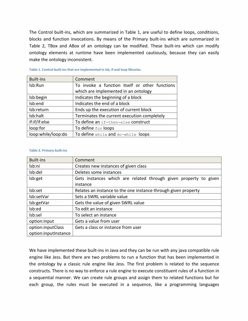
The Control built-ins, which are summarized in Table 1, are useful to define loops, conditions,
blocks and function invocations. By means of the Primary built-ins which are summarized in
Table 2, TBox and ABox of an ontology can be modified. These built-ins which can modify
ontology elements at runtime have been implemented cautiously, because they can easily
make the ontology inconsistent.
Table 1. Control built-ins that are implemented in lsb, if and loop libraries.
Built-ins Comment
lsb:Run To invoke a function itself or other functions which are implemented in an ontology
lsb:begin Indicates the beginning of a block
lsb:end Indicates the end of a block
lsb:return Ends up the execution of current block
lsb:halt Terminates the current execution completely
if:if/if:else To define an if-then-else construct
loop:for To define for loops
loop:while/loop:do To define while and do-while loops
Table 2. Primary built-ins
Built-ins Comment
lsb:ni Creates new instances of given class
lsb:del Deletes some instances
lsb:get Gets instances which are related through given property to given instance
lsb:set Relates an instance to the one instance through given property
lsb:setVar Sets a SWRL variable value
lsb:getVar Gets the value of given SWRL value
lsb:ed To edit an instance
lsb:sel To select an instance
option:input Gets a value from user
option:inputClass option:inputInstance
Gets a class or instance from user
We have implemented these built-ins in Java and they can be run with any java compatible rule
engine like Jess. But there are two problems to run a function that has been implemented in
the ontology by a classic rule engine like Jess. The first problem is related to the sequence
constructs. There is no way to enforce a rule engine to execute constituent rules of a function in
a sequential manner. We can create rule groups and assign them to related functions but for
each group, the rules must be executed in a sequence, like a programming languages

statements. The second problem is related to SWRL variables. The SWRL variables are treated
as universally quantified, and their scope is limited to the given rule. Therefore, a variable
which is defined in one rule is inaccessible from other rules. We have solved these problems in
the RE. The RE can execute all rules of a function in the specified order of its RDFList. Also, by
means of some special built-ins, SWRL variables can be shared between different rules and
global variables can be defined.
We have developed the RE as a set of java APIs. It can execute all types of SWRL atoms, and
also Control Built-ins which have been summarized in Table 1 are meaningful to the RE. The RE
interface provides a means for the software system to get connected to the RE. We also have
developed a simple plugin for protégé-OWL which facilitates implementing of functions in
ontology. By using this plugin we can first create a SRAD project to generate a BO as a start
point for implementing desired functions, and then any function can be implemented and
tested using protégé-OWL SWRL rules editor. When the RE is invoked to run a function, it first
processes inputs and outputs datatypes and variables, then creates required data structures,
next it fetches and executes the rules which are located in the RDFList of the function. Indeed,
the RE acts as an interpreter that translates control built-ins and invokes primary built-ins.
For example, suppose that we want to implement a recursive function like fac that calculates
the factorial of an integer value. For this purpose, we should create following rules:
Input rule: int(?x)
Output rule: long(?y)
Body Rules:
Rule A: swrlb:lessThan(?x,2) lsb:setVar(?y, 1) ∧ lsb:return(1)
Rule B: swrlb:greaterThan(?x,1) ∧ swrlb:subtract(?k,?x,1) ∧ lsb:Run(?o,fac,?k)
∧ swrlb:multiply(?y,?o,?x)
Input and output rules indicate datatypes and formal variables. The RE first interprets these two
rules and creates required data structures and puts the inputs and outputs in them. Then the
RE fetches and executes Rule A. If input value, which is bound to the x is less than 2, then
lsb:setVar built-in binds 1 to y as output value and then returns. If x value is greater than 1
then the function fac calls itself by lsb:Run with x-1 as its input.
4 SRAD Viewpoint From the Object-Oriented viewpoint, a software program primarily consists of some objects
that interact with each other and provide requested services to the end users. In the Structured
methodologies, the software program consists of some modules, so that data items flow
between different modules and each module performs some computations and transformation
on input items then generates output ones and eventually it passes them to other modules or
external entities.
From SRAD point of view, a software program consists of formal description and
implementation of requested functionalities in the AO. The AO encompasses both business
logic and dynamic model of the software. All of system data is stored in the DO. Indeed, the
Abox of DO is the data model of software and its Tbox, like a database, is a place where the
system data is stored as sets of instances. Although, DO acts as a data repository hear, storing
the DO in a database is very important for security and efficiency reasons. Each functionality in
the AO may have some inputs which are received from other functionalities or end users and
generates outputs and finally returns them to the invocator.
To describe and implement any software system functionalities in AO, it’s a good idea to use BO
as a start point. Therefore, each functionality in the AO should be represented as a subclass of
Function, the inputs and outputs can be described using SWRL rules and the body of
functionality can be implemented using some SWRL built-ins. To describe and implement the
software functionalities in AO, the proposed method in Section 3.2 can be used. Inputs-outputs
of functionalities can be primitive or compound. Primitives can be defined using subclasses of
Datatype and to define compound items, DO classes can be used as their datatypes. In fact,
each subclass of Datatype represents a primitive data type and any class which is defined in the
DO can be used as compound data type. For example, if we define the inputs of a function with
the rule int(?x)^c(?y)-> then the function has two inputs; first an integer and second an
instance of class c. It’s very important that all elements of the DO be available in the AO, so the
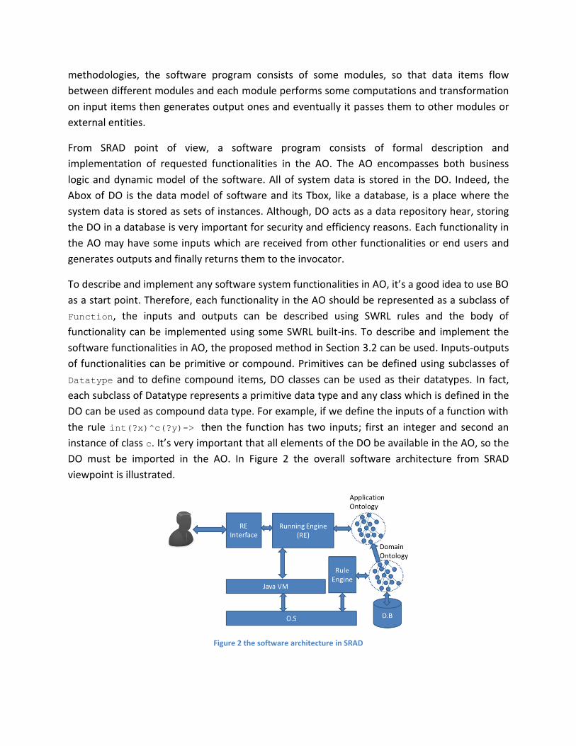
DO must be imported in the AO. In Figure 2 the overall software architecture from SRAD
viewpoint is illustrated.
Figure 2 the software architecture in SRAD

In Figure 2, the arrow that connects the Domain Ontology to the Application Ontology
means the DO is imported in the AO. In a real system, although Abox of DO usually is small, its
Tbox can be enormous and it’s not rational to keep this large amount of instances in a flat text
file. This is good idea to store DO in a database using one of available approaches. The arrow
between the D.B and the Domain ontology means that the DO is stored in the database. The
Rule engine can be applied to the Domain Ontology for deducing new facts from existing
ones based on SWRL rules and OWL axioms. Therefore, in the illustrated architecture, the
software program can profit from both DBMS and rule engine advantages. The Application
ontology should be available for the RE. It’s because just as the end user requests a
functionality through the RE interface, the RE must load the functionality and other related
ones from the Application ontology then perform the operations which are described in the
body of requested functionality, finally send back suitable response to the end user through RE
interface.
5 SRAD Model The SRAD paradigm for software development has four general phases, including Cognition,
Arrangement, Construction and Tryout. The first phase is Cognition and two main activities
which should be performed in this phase are DO preparing and requirements elicitation. The
output products of the Cognition activities are the DO and the requirements specifications,
which are utilized by brief design activity in the next phase which is Arrangement phase. In the
Arrangement phase, the software developers should identify all functionalities of the software
then describe them and their inputs-outputs in the AO hierarchically. In fact, the hierarchical
model of functionalities in the AO shows the architecture of the software. Some of
functionalities get their inputs from end users and may send outputs back to them. Software
developers should find such functionalities and design a reasonable interface for them. The
output products of the Arrangement phase are empty AO and interface model which are used
in the Construction phase. In the Construction phase, the software developers should define
how the functionalities do their tasks and implement them in the AO by utilizing the method
which has been explained in section 3.2. The user interface of functionality should be
implemented by using sets of pages, forms and other required components. The last phase in
SRAD paradigm is Tryout. In this phase, all functionalities should be tested by using different
techniques and tools.
The SRAD paradigm is illustrated with Figure 3. In this figure, different phases are separated by
dotted lines, each oval represents an activity in a phase, each rectangle represents a production
that is produced in a phase and a directed line, based on its direction, represents that a
production is produced by an activity or an activity uses a production to perform its tasks.
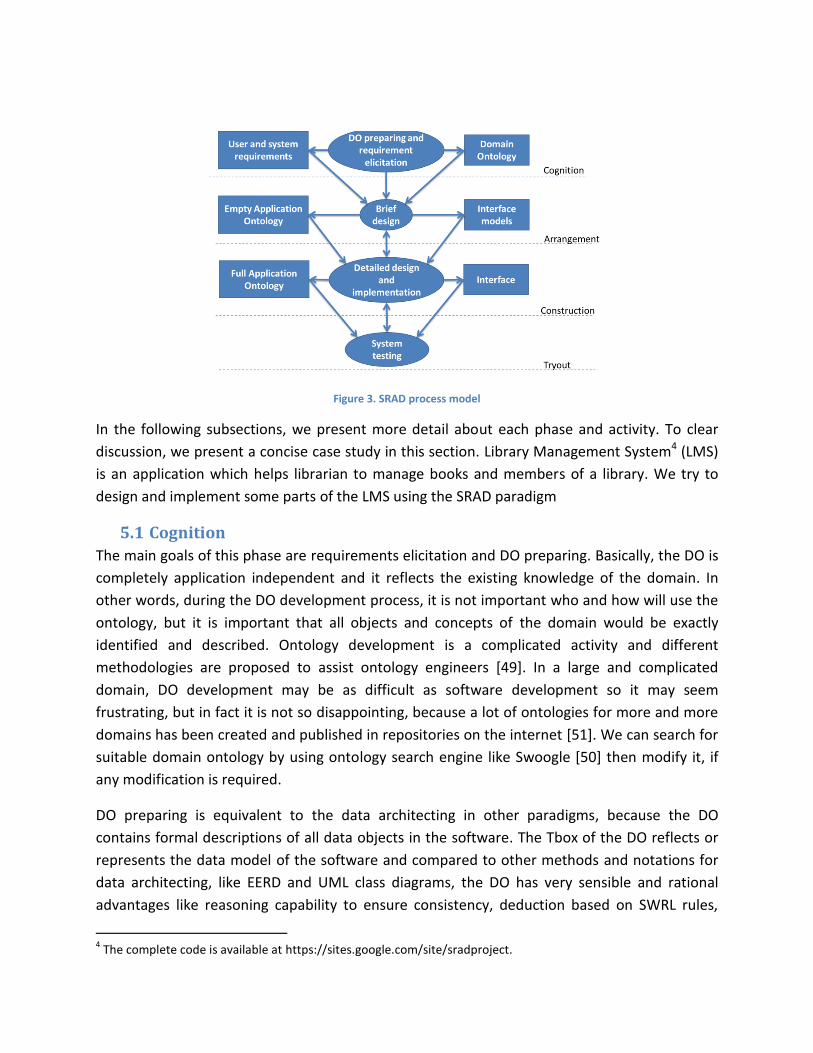
Figure 3. SRAD process model
In the following subsections, we present more detail about each phase and activity. To clear
discussion, we present a concise case study in this section. Library Management System4 (LMS)
is an application which helps librarian to manage books and members of a library. We try to
design and implement some parts of the LMS using the SRAD paradigm
5.1 Cognition
The main goals of this phase are requirements elicitation and DO preparing. Basically, the DO is
completely application independent and it reflects the existing knowledge of the domain. In
other words, during the DO development process, it is not important who and how will use the
ontology, but it is important that all objects and concepts of the domain would be exactly
identified and described. Ontology development is a complicated activity and different
methodologies are proposed to assist ontology engineers [49]. In a large and complicated
domain, DO development may be as difficult as software development so it may seem
frustrating, but in fact it is not so disappointing, because a lot of ontologies for more and more
domains has been created and published in repositories on the internet [51]. We can search for
suitable domain ontology by using ontology search engine like Swoogle [50] then modify it, if
any modification is required.
DO preparing is equivalent to the data architecting in other paradigms, because the DO
contains formal descriptions of all data objects in the software. The Tbox of the DO reflects or
represents the data model of the software and compared to other methods and notations for
data architecting, like EERD and UML class diagrams, the DO has very sensible and rational
advantages like reasoning capability to ensure consistency, deduction based on SWRL rules,
4 The complete code is available at https://sites.google.com/site/sradproject.

reusability of domain, interoperability etc. In the SRAD paradigm, the DO plays two roles. In the
first role, the Tbox of DO is equivalents to the data model of the software system and
represents the data architecture of the software system. In the second role, the Abox of the DO
is a place where all data objects are stored.
Requirement elicitation is another activity in Cognition phase which should be accomplished by
using well known requirement engineering methods and techniques. Some of non-functional
requirements may be described in the DO and other ones should be noticed in the AO. For
example, suppose this non-functional requirement in the LMS: “a member can borrow up to
three books at the same time”. This requirement can be described in the DO using an OWL
cardinality restriction and also can be considered in the AO when related functionality is being
implemented. Functional requirements can lead developers to identify most of important
functionalities. Some of the functionalities represent an operational description of the DO
properties. For example, in the DO of the LMS a property like hasBorrowed, relates an
instance of class Member to up to three instances of class Book. In fact, this property also refers
to a functionality that software system should provide and enable librarians to borrow books to
members.
5.2 Arrangement
To design a software system briefly in Arrangement phase, both the AO and the user interface
model should be created. In SRAD paradigm, software architecture which should be described
in the AO represents all software functionalities in a hierarchical organization. All of
functionalities which have been identified in the phase Cognition should be arranged in the AO
by creating an ontology class for each of them. The BO has some initial classes and properties,
so it provides a good foundation to create the AO. For example, the class Function is
superclass of all functionalities classes also properties IN and OUT are used to describe the
input-output items of each of functionalities.
In first level, the whole software can be considered as one functionality to itself, because it
receives some inputs from external objects and after performing needed processing, it
generates the outputs as results. By following a top-down approach, in level 1, the whole
software system is considered as a single functionality and a direct subclass of Function is
created for that. If the software developers are going to develop two or more software systems
in target domain, a direct subclass of Function should be created for each of them. Now with
the aid of the organizational chart of business, gathered requirements, and the DO properties,
the software developers should identify level 2 functionalities. In general, a functionality in level
x provides its services and performs its operations by invoking some other functionalities from
level x+1. In other words, each functionality may have some sub functionalities which should be
created as direct subclasses of super functionality class. When a functionality could perform its

operations by invoking some SWRL built-ins, it’s not needed to divide it to some sub
functionalities. A functionality in a level of hierarchy can have more than one super
functionalities from higher levels. This improves reusability of the software architecture
elements.
After identifying the functionalities and arranging them in the AO, software developers should
describe input-output items of them by using properties IN for the inputs and property OUT for
the outputs. A functionality may sometimes need to get its inputs from the end users or
represent outputs directly to them. Such functionalities need user interfaces to interact with
the end users, then after arranging functionalities in the AO, the developers should design
appropriate user interfaces for them. As it was explained in Section 3.2, some built-ins may
have user interfaces, so that they facilitates the designing of related functionalities user
interface and free developers from involving in the user interface details.
Figure 4. A brief structure of LMS application ontology
For example, again consider LMS which its AO is illustrated with Figure 4 partly. In first level we
have created class LMS in the AO as subclass of Function. The LMS represents the whole
software system as a functionality. In level 2, we have create classes BorrowBook,
DeliverBook, MemberManage, BookManage and Login as subclasses of LMS. Hear we have
expanded the BorrowBook with some sub functionalities like SelectBook, SelectMember,
UpdateBookInf, UpdateMemberInf and CheckConditions. It’s because that, when a member
wants to borrow a book from a librarian, first the librarian should select the member and then
select the books that the member wants to, after these, CheckConditions should be invoked

to verify if the member is allowed to borrow the books, and finally if the member is allowed the
books and the member information should be updated in the DO.
5.3 Construction
As it is illustrated with Figure 3, the input products of the Construction phase are empty AO and
user interface model. The empty AO contains all of the software functionalities as a class
hierarchy, and input-output items of the functionalities are described using SWRL rules. The
empty AO doesn’t have any implementation so all of functionalities which are identified in the
previous phase should be implemented in the Construction phase using a down-top approach.
The implementation activity begins with the functionalities in the lower levels of class hierarchy
which don’t have any sub functionalities. The functionalities can be implemented by using
SWRL built-ins just as proposed method in Section 3.2. In fact, all processing and computations
that are needed in the functionalities are done by invoking proper built-ins. It’s very important
that the implementation of required built-ins be available to the developers.
After the implementation of all sub functionalities of a functionality, it’s time to implement the
super functionality. The functionalities in the higher levels of class hierarchy are mainly
implemented by invoking their sub functionalities through the built-in Run which has been
described in Table 2. We believe illustrated built-ins in Table 1 and Table 2 satisfy primitive
demands of developers, but undoubtedly in some cases developers need to create new built-
ins. Although creation of new built-ins can be difficult and time consuming, the demand for new
built-ins will be reduced with time in the future projects.
When the functionalities are being implemented by developer, they can find some of them
which reside in higher levels of class hierarchy, don’t need to be implemented. The main
responsibility of such functionalities is providing interfaces to enable the end users to select
and invoke one of their sub functionality. To design user interface in detail and implement it,
the developers should only think about functionalities that don’t need to be implemented and
provide proper interfaces for them. Some other functionalities which need to be implemented,
also need to interact with end users directly. This interaction should be done through the user
interfaces of built-ins. In fact, much complexity of user interface design and implementation
should be solved in the built-ins level. Then the user interface design activity in Construction
phase only includes designing and implementing of a small number of user interface
components which enable the end users to select and invoke required functionalities.
5.4 Tryout
In this phase, developers should conduct some tests to ensure that all functionalities are valid
and all user requirements are met by them. Testing process begins in the small and progress
towards testing in the large, so the functionalities that reside in the lower levels of the class
hierarchy should be tested before their super functionalities. We have developed a test bed as

a protégé plugin which enables software testers to invoke the functionalities with different
inputs to check them up for errors, requirement conformance and performance. The Tryout
phase can be concurrent with the Construction phase so that after implementation of each
functionality it can be tested instantly. Software testers should design some test cases which
have high probability of finding errors. After testing of the root of class hierarchy, the software
is likely to have no errors or problems.
6 Evaluation Although using the SW technologies in SE is not a new subject and currently there are many
approaches to that, we believe that SRAD is the first step to combine SE and the SW
completely, because in SRAD the software model and code are both in the ontologies and the
AO and the DO are everything. Compared to traditional software development paradigms that
the developers using them should create models to understand software functionalities and
finally generate codes from them and put the models away, In SRAD we create models not only
for design and maintenance purposes, but to execute software from them. In other words, the
SRAD model leads the developers to create runnable models so that they don’t need to
generate code from them; they only use some tools to execute software from models directly.
Software systems which are developed with SRAD don’t need a direct interaction with a DBMS.
In fact instead of database tables and tuples, the software systems data is stored as a set of
ontology instances and developers need suitable APIs to interact with the ontology elements.
By using ontology instead of data base, we can profit from both reasoners and rule engine
capabilities like consistency checking and fact finding. The developers can describe and define
some facts, statements and relationships by ontology language axioms which are impossible to
be described by data bases modeling languages and tools. But data bases have some powerful
attributes like efficiency, safety, security, recoverability etc, which shouldn’t be neglected. By
putting ontologies in databases we profit from both DBMS efficiency and ontology
expressiveness power.
Rapid Application Development (RAD) models have recently had many proponents. By using
these models, the developers concentrate on reduction of software production time and costs
and they often miss complete documentations, so the developed software with RAD models
would be very hard to maintain. It’s because a clear understanding of a software system plays a
prominent role in software maintenance activity, and the understanding of a software system
with missing documentations can be dramatically hard for maintenance team. Basili has said
“Most software systems are complex, and modification requires a deep understanding of the
functional and non-functional requirements, the mapping of functions to system components,
and the interaction of components.” [9]. SRAD is a rapid model, so the software maintenance is

expected to be hard, but indeed it can be very easy and straightforward. It’s because using
ontologies as model and code forms the basis of SRAD, and unlike almost all of other
paradigms, in SRAD the developers don’t put away these semantic models, even after software
implementation. Consequently, the maintainers can understand the software easily with the
aid of the AO and the DO. We believe that compared to other software paradigms, software
maintenance in the SARD can be very facile and straightforward.
Reusability is another advantage of SRAD. In the Cognition phase, The DO can be reusable and
the developers can find appropriate domain ontology from online repositories and Also in the
Arrangement and the Construction phases, SWRL built-ins are reusable. In addition to the DO
and the built-ins, the functionalities which are described and implemented in the AO can be
reusable. It’s because the AO of a software system can be populated on the web and its
elements can be referred through their Internationalized Resource Identifiers (IRIs) in the
Arrangement or Construction phases of other software systems. In face, the distributed nature
of web is inherited by the AO then in addition to reusability of functionalities through IRIs, we
can distribute the AO among multiple sites and divide processing load between multiple
machines.
7 Suggestions and Conclusion The SW technologies can improve the SE paradigms to reduce the time and the cost of software
production and maintenance. The SW languages provide facilities to describe the spread of
information on the web formally by creating some special semantic models, which are called
ontologies. We have used these semantic models to describe the domain and the
functionalities of application software. The software documentations are more than likely to be
incomplete in other RAD paradigms and then although they decrease production expenses,
maintenance costs might increase. It’s because the understanding of software is very pivotal to
maintenance process. Consequently, RAD paradigms may increase the overall expenses of
software production, especially when domain of software is change frequently. In SRAD, model
is software and software is model, then we execute the software from model directly. These
models are very advantageous to software maintenance.
We have developed some primitive tools including the RE, the RE Interface and the SRAD
protégé plugin which enable desktop application software developing with SRAD. Undoubtedly,
they might be insufficient and might be difficult to use, also these tools don’t support web
application. It’s a good idea to implement the RE as a complete application server. For this
purpose, we intend to combine the RE with Apache Tomcat5 and create built-ins with web
based user interface. Also, we can develop some tools to translate ordinal object oriented
5 http://tomcat.apache.org/

software systems to SRAD like ones. Such translation is useful to maintenance of software
system with mutable domain.
8 References
[1]. Berners-Lee, T., Hendler, J., and Lassila, O., "The Semantic Web". Scientific American Magazine, May 17 2001, pp. 29-37.
[2]. Gruber, T.R., “A translation approach to portable ontologies. Knowledge Acquisition, Vol. 5, No. 2, pp.199–220, Available: http://ksl-web.stanford.edu/KSL_Abstracts/KSL-92-71.html.
[3]. Manola, F., Miller, E., “RDF Primer”, W3C Recommendation, February 10 2004, Available: http://www.w3.org/TR/rdf-primer/.
[4]. Brickley, D., Guha, R.V., “RDF Voabulary Description Language 1 0: RDF Schema”, W3C Recommendation,
February 10 2004, Available : http://www.w3.org/TR/rdf-schema/.
[5]. K.Smith, M., Welty, C., L. McGuinness, D., “OWL Web Ontology Language Guide”, W3C Recommendation, February 2004, Available: http://www.w3.org/TR/owl-guide/.
[6]. Horrocks, I., et al., “SWRL: A Semantic Web Rule Language Combining OWL and RuleML”, W3C Member Submission, May 21 2004, Available: http://www.w3.org/Submission/SWRL/.
[7]. Hitzler, P., et al., “OWL 2 Web Ontology Language Primer”, W3C Recommendation, October 27 2009, Available: http://www.w3.org/TR/owl-primer/.
[8]. Kogut, P., “Augmented Software Cognition”, In Proc. of Second International Workshop on Semantic Web
Enabled Software Engineering (SWESE), 2006.
[9]. Basili, V.; and Mills, H., “Understanding and Documenting Programs”, IEEE Transactions on Software Engineering SE, vol 8(3), 1982, pp. 270-283.
[10]. Vasudevan, S., Wilemon, D., “Rapid application development: major issues and lessons learned”, Innovation in Technology Management - The Key to Global Leadership. PICMET '97: Portland International Conference on Management and Technology, 1997.
[11]. Gerber A.J., Van der Merwe A.J. and Alberts R., “Practical Implications of Rapid Development Methodologies”, In Proc. of the Computer Science and Information technology Education Conference, CSITEd-2007, Mauritius, 16-18 November 2007, ISBN: 978 99903 87 47 6.
[12]. Friedman, E., Jess: Rule Engine for Java Platform, Available: http://herzberg.ca.sandia.gov/jess/
[13]. Bossche. M.V., et al., “Ontology Driven Software Engineering for Real Life Applications”, In Proc. of Second International Workshop Semantic Web Enabled Software Engineering (SWESE), 2006.
[14]. Athanasiadis, N., et al., “Ontologies, JavaBeans and Relational Databases for enabling semantic programming”, In Proc. of 31st Annual International Computer Software and Applications Conference(COMPSAC), 2007, pp. 341-346.
[15]. Zhao, Y., et al., “Ontology Classification for Semantic-Web-Based Software Engineering”, IEEE Transaction on Services Computing, Vol. 2, 2009, pp. 303-317.
[16]. Tetlow, P., et al., “Ontology Driven Architectures and Potential Uses of the Semantic Web in Software Engineering”, W3C, Semantic Web Best Practices and Deployment Working Group, 2006
[17]. Knublauch, H., “A Semantic Web Primer for Object-Oriented Software Developers”, W3C, Semantic Web Best Practices and Deployment Working Group, 2006.
[18]. Abran, A., et al., “SWEBOK - Guide to the Software Engineering Body of Knowledge 2004 version”. IEEE Computer Society, 2004, Available: http://www.swebok.org.

[19]. Wongthongtham, P., et al., “Software Engineering Sub-Ontology for Specific Software Development”, In Proc. of the 29th Annual IEEE/NASA Software Engineering Workshop (SEW), 2005, pp. 27-33.
[20]. Wongthongtham, P., et al., “Towards 'Ontology'-based Software Engineering for Multi-site Software Development”, In Proc. of 3rd IEEE International Conference on Industrial Informatics (INDIN), 2005, pp. 362-365.
[21]. Wongthongtham, P., et al., “Information Engineering of a Software Engineering Ontology”, In Proc. of 3rd IEEE International Conference on Industrial Informatics (INDIN), 2005, pp. 366-371.
[22]. Wongthongtham, P., et al., “Ontology-based Software Engineering- Software Engineering 2.0”, In Proc. of 19th Australian Conference on Software Engineering, 2009, pp. 13-23.
[23]. Wongthongtham, P., et al., “A Software Engineering Ontology as Software Engineering Knowledge Representation”, In Proc. of Third International Conference on Convergence and Hybrid Information Technology, 2008, pp. 668-675.
[24]. Hawker, J.S., Ma, H., and Smith, R.K., “A Web-Based Process and Process Models to Find and Deliver Information to Improve the Quality of Flight Software”, In Proc. of 22nd Digital Avionics Systems Conference
(DASC’03),vol. 1, pp. 12-16, Oct. 2003.
[25]. Liao, L., Qu, Y., and Leung, H.K.N., “A Software Process Ontology and Its Application,”In Proc. of First International Workshop Semantic Web Enabled Software Engineering, Nov. 2005.
[26]. Thaddeus, S., Raja, S.V.K., “Ontology-Driven Model forKnowledge-Based Software Engineering”, In Proc. of 18th International ConferenceSoftware Engineering and Knowledge Engineering (SEKE), July, 2006, pp. 337-342.
[27]. Yang, D., Xue, M., “Software process paradigm and its constraint mechanisms”, IEEE 2nd International Conference on Software Engineering and Service Science (ICSESS), 2011 , pp. 842-845.
[28]. Siegemund, K., Thomas, E.J, Zhao, Y., Pan, J., and Assmann, U., “Towards Ontology-driven Requirements Engineering”, In Proc of 7
th International Workshop on Semantic Web Enabled Software Engineering (SWESE),
October 2011.
[29]. Riechert, T., Lauenroth, K., Lehmann, J., Auer, S., ”Towards Semantic based Requirements Engineering”, In: Proc. of the 7th International Conference on Knowledge Management (I-KNOW), 5–7 September, Graz, Austria, 2007.
[30]. Henninger, S., Ashokkumar, P., “An Ontology-Based Metamodel for Software Patterns”, In Proc. of 18th International Conference on Software Engineering and Knowledge Engineering (SEKE), San Francisco, July 5-7, 2006.
[31]. Duddukuril, R., Prabhakar, T.V., “Helping Architects In Retrieving Architecture Documents: A Semantic Based Approach”,In Proc. of the Second Workshop on Sharing and Reusing architectural Knowledge Architecture, Rationale, and Design Intent, 2007.
[32]. Wenzel, K., “Ontology-Driven Application Architectures with KOMMA”, In Proc of 7th
International Workshop on Semantic Web Enabled Software Engineering (SWESE), October 2011.
[33]. Zhou, H., Chen, F., Yang, H., “Developing Application Specific Ontology for Program Comprehension by Combining Domain Ontology with Code Ontology”, In Proc. of the 8
th International Conference on Quality
Software, 2009, pp. 225-234.
[34]. Yoshikawa, T., Hayashi, S., Saeki, M., “Recovering Traceability Links between a Simple Natural Language
Sentence and Source Code Using Domain Ontologies”, In Proc. of International Conference on Software
Maintenance (ICSM), Edmonton, Canada, 2009, pp. 551-556.
[35]. Hyland-Wood, D., et al., “Towards a software maintenance methodology using Semantic Web techniques and paradigmatic documentation modeling”, Journal of IET Software, Vol. 2, No. 4, 2008, pp. 337–347.

[36]. Cai, L., Tong, W., Liu, Z. and Zhang, J., “Test Case Reuse Based on Ontology”, In Proc of 15th IEEE Pacific Rim International Symposium on Dependable Computing, 2009, pp. 103-108.
[37]. Li, H., Chen, F., et al., “An Ontology-based Approach for GUI Testing”, In Proc. of 33rd Annual IEEE International Computer Software and Applications Conference, 2009, pp 632-633.
[38]. Xue-Mei, L., Guochang, G., Yong-Po, L. and Ji, W., “Research and Implementation of Knowledge Management Methods in Software Testing Process”, In Proc. of World Congress on Computer Science and Information Engineering, 2009, pp. 739-743.
[39]. Horridge, M., Knublauch, H., Rector, A., Stevens, R., and Wroe, C., “A practical guide to building owl ontologies using the Protege-OWL plugin and CO-ODE tools. Online tutorial”, The University Of Manchester and Stanford University, August 27 2004.
[40]. Sharma, D. K., Johnson, T. M., Solbrig, H. R., and Chute, C. G., “Transformation of protégé ontologies into the eclipse modeling framework: A practical use case based on the foundational model of anatomy”, In 8
th
International Protégé Conference, Madrid, Spain, July 2005.
[41]. Knublauch, H., “Protege-OWL API Programmer's Guide”, June 30, 2010, Available: http://protegewiki.stanford.edu/wiki/ProtegeOWL_API_Programmers_Guide.
[42]. Suihua, W., Xiaodan, Z., “A high-efficiency ontology storage and query method based on relational database”, In Proc. of International Conference on Electrical and Control Engineering (ICECE), 2011, pp. 4253-4256
[43]. Khalid, A., Shah, S.A.H. and Qadir, M.A., “OntRel: An Ontology Indexer to store OWL-DL Ontologies and its
Instances”, In Proc. of International Conference of Soft Computing and Pattern Recognition, 2009, pp 478-483.
[44]. Astrova, I., Korda, N., Kalja, A., “Storing OWL ontologies in SQL relational databases”, Iternational Journal of Electrical, Computer, and Systems Engineering, Vol. 1, No. 4, 2007, pp 242-247.
[45]. Zhou, J., Ma, L., Liu, Q., Zhang, L., Yu, Y., and Pan, Y., “Minerva: An OWL ontology storage and inference system”, In Proc. of Asia Semantic Web Conference, 2006, pp.429—443.
[46]. Knublauch, H., “Ramblings on Agile Methodologies and Ontology-Driven Software Development”, Position Paper for the First Workshop on Semantic Web Enabled Software Engineering(SWESE), 2005.
[47]. Kalyanpur, A., “Automatic Mapping of OWL Ontologies into Java”, In Proc. of .In 16th International Conference on Software Engineering and Knowledge Engineering (SEKE04), Banff, Canada, 2004.
[48]. Pressman, R.S., “Software engineering: a practitioner’s approach”, McGraw-Hill series in computer science, 5
th Edition, Chap. 16, 2001.
[49]. John, S., “Leveraging Traditional Software Engineering Tools to Ontology Engineering under a New Methodology”, In Proc. of 5
th International Conference on Future Information Technology (FutureTech), 2010
[50]. Swoogle: Semantic Web Search,. University of Maryland Baltimore, County (UMBC), 2006. Available: http://swoogle.umbc.edu.
[51]. Siricharoen W.V., “Merging Ontologies for Object Oriented Software Engineering”, In Proc. of Fourth International Conference on Networked Computing and Advanced Information Management, 2008, pp. 525-530.
[52]. Morien, R., Wongthongtham, P., “Supporting Agility in Software Development Projects –Defining a Project Ontology”, In Proc. of Second IEEE International Conference on Digital Ecosystems and Technologies (IEEE DEST), 2008, pp. 229-234.


![SPECKLE NOISE REDUCTION IN BREAST ULTRASOUND ......SRAD [4], Wiener filter [5], and Wavelet thresholding [6]. In our work, we recommend a novel algorithm (Srad Median Unsharp) SMU](https://img.pdfslide.net/doc/110x75/60e3b7eab54f1871f51a6090/speckle-noise-reduction-in-breast-ultrasound-srad-4-wiener-filter-5.jpg)