Embed Size (px)
Citation preview
Applied Energy 88 (2011) 4411–4423
Contents lists available at ScienceDirect
Applied Energy
journal homepage: www.elsevier .com/locate /apenergy
A comparative investigation of various greenhouse heating options usingexergy analysis method
Arif Hepbasli ⇑Department of Mechanical Engineering, College of Engineering, King Saud University, P.O. Box 800, Riyadh 11421, Saudi Arabia
a r t i c l e i n f o a b s t r a c t
Article history:Received 13 March 2011Received in revised form 4 May 2011Accepted 15 May 2011Available online 12 June 2011
Keywords:EnergyExergyGreenhousesLowExRenewable energySustainability
0306-2619/$ - see front matter � 2011 Elsevier Ltd. Adoi:10.1016/j.apenergy.2011.05.022
⇑ Tel.: +966 14676677; fax: +966 14672636.E-mail addresses: [email protected], arifhepb
This study deals with modeling and analyzing the performance of greenhouses from the power plantthrough the heating system to the greenhouse envelope using exergy analysis method, the so-calledlow exergy or LowEx approach, which has been and still being successfully used in sustainable buildingsdesign, for the first time to the best of the author’s knowledge. For the heating applications, three optionsare studied with (i) a solar assisted vertical ground-source heat pump greenhouse heating system, (ii) awood biomass boiler, and (iii) a natural gas boiler, which are driven by renewable and non-renewableenergy sources. In this regard, two various greenhouses, the so-called small greenhouse and large green-house, considered have heat load rates of 4.15 kW and 7.5 MW with net floor areas of 11.5 m2 and 7.5 ha,respectively. The overall exergy efficiency values for Cases 1–3 (solar assisted vertical ground-source heatpump, natural gas boiler and wood biomass boiler) of the small greenhouse system decrease from 3.33%to 0.83%, 11.5% to 2.90% and 3.15% to 0.79% at varying reference state temperatures of 0 to 15 �C whilethose for Cases 1 and 2 (wood biomass and natural gas boilers) of the large greenhouse system decreasefrom 2.74% to 0.11% and 4.75% to 0.18% at varying reference state temperatures of �10% to 15 �C. Theenergetic renewability ratio values for Cases 1 and 3 of the small greenhouse as well as Case 1 of the largegreenhouse are obtained to be 0.28, 0.69 and 0.39, while the corresponding exergetic renewability ratiovalues are found to be 0.02, 0.64 and 0.29, respectively.
� 2011 Elsevier Ltd. All rights reserved.
1. Introduction
Various policies have been formulated in many countriesaround the world to aim at decreasing carbon dioxide emissions,while many countries have also established policies towardsincreasing the share in renewable energy utilization. Both are partsof a global response to the climate change [1]. Especially in analyz-ing 100% renewable energy systems, which will be technically pos-sible in the future, and may even be economically beneficialcompared to the business-as-usual energy system, energy savings,efficient conversion technologies and the replacement of fossilfuels with renewable energy are essential elements to consider [2].
As a consequence of the latest reports on climate change andthe need for a reduction in CO2 emissions, huge efforts must bemade in the future to conserve high quality, or primary energy, re-sources [3,4]. A new dimension will be added to this problem ifcountries with fast growing economies continue to increase theirconsumption of fossil energy sources in the same manner as theydo now. Even though there is still considerable energy saving po-tential in building stock, the results of the finished IEA ECBCS An-
ll rights reserved.
nex 37, Low Exergy Systems for Heating and Cooling of Buildings,show that there is an equal or greater potential in exergy manage-ment [4,5].
The amount of energy used in agricultural production, process-ing and distribution is significantly high. Sufficient supply of theright amount of energy along with its effective and efficient utiliza-tion is necessary for an improved agricultural production. It hasalso been reported that crop yields and food supplies are directlylinked to energy [6].
Various types of heating systems have been used in green-houses for meeting the heating and cooling requirements. Steamor hot water radiation systems, which utilize steam or hot watersupplied through pipe networks running through the greenhouse,and hot air unit heaters, are among some applications. The heatingrequirements of the greenhouse may be generally met by thesesystems, but the temperature distribution patterns within thegreenhouse associated with such systems are readily influencedby the outdoor weather conditions. In addition, such systems areusually not able to control and maintain the required humidity lev-els within the greenhouse, which also affect the growth of crops.Thus, there is a great potential in employing a heat-pump systemfor greenhouse air-conditioning based on its ability to performthe multi-function of heating, cooling and dehumidification [7].
Nomenclature
A area (m2)c specific heat (kJ/kgK)COP coefficient of performance (–)_E energy rate (W)_Ex exergy rate (W)f approximation factor (–), factor (–)F factor (–)l length (m)N percentage of equipment resistanceP power (W)p specific power, pressure (W/m2, N/m2)_Q heat transfer rate (kW)R pressure drop of the pipe (Pa/m), thermal resistance
(m2 K/W), ratio (–)SI sustainability index (–)T temperature (K)_v volumetric flow rate (m3/s)V volume (m3)
Greek lettersg energy efficiency (–)w exergy efficiency (–)D difference
Subscriptsair indoor airaux auxiliary energy requirementc construction typecirc circulationdis distribution systemEn energeticEx exergeticel electricityenv environmentGe generationgp generator positiongh greenhouseHS heating system
h heatheat heateri indoor, counting variablein input, inletins insulationl lightingmax maximumN neto outdoor, occupantsp primary energy, constant pressureq qualityR renewable energyr renewabilityref referenceret returnS solars sourcetd temperature droptot totalusf usefulV ventilationw wind0 reference (dead) state
Superscriptsover dot rate
AbbreviationsCOP coefficient of performanceECBCS energy conservation in buildings and community sys-
tems programmeIEA international energy agencyLGH large greenhouseLowEx low exergySAVHP solar assisted vertical ground-source heat pumpSGH small greenhouse
4412 A. Hepbasli / Applied Energy 88 (2011) 4411–4423
A geothermal heat pump or ground-source heat pump (GSHP) isa central heating and/or cooling system that pumps heat to or fromthe ground to provide heating, air conditioning and, in most cases,hot water. Studies have shown that approximately 70% of the en-ergy used in a GSHP system is renewable energy from the ground[8]. In this regard, GSHP systems have become increasingly popularfor both residential and commercial heating and cooling applica-tions. These systems have been recognized to provide viable, envi-ronmentally friendly alternatives to conventional unitary systems.They can make significant contributions to reductions in electricalenergy utilization, and offer more effective demand-side manage-ment [9].
There are basically six different ground-source heating systems,which are applied to greenhouses: (a) finned pipe, (b) standardunit heaters, (c) low-temperature unit heaters, (d) fan-coil units,(e) soil heating, and (f) bare tube [10]. The performance of thelow temperature unit heaters falls between that of standard unitheaters and fan-coil units. Among the above-mentioned heatingsystems, the soil heating (ground heating by coils embedded tothe ground), which involves using the floor of the greenhouse asa large radiator, requires lower heating fluid temperatures, andespecially helpful to protect the plant root zone temperature,rather than simply heating the air. In addition, because the air is
not needed to heat too much, energy is saved, and lower heatingfluid temperature increases the COP values [10,11].
Exergy may be defined in various ways as follows [12,13]: (i)The quality of energy , (ii) The capacity of energy to cause change,(iii) The maximum work that can be obtained from a given form ofenergy using the environmental parameters as the reference state,and (iv) A measure of the departure of the state of the system fromthe state of the environment. In this regard, it should be noticedthat exergy is always evaluated with respect to a reference envi-ronment (i.e., dead state), while the selection of dead state condi-tions is arbitrary, but depends on some criteria. Exergy analysishas been viewed as a very useful tool, which can be successfullyutilized in the design, simulation and performance assessment ofenergy related systems. Exergy analysis is relevant in identifyingand quantifying both the consumption of useful energy (exergy)used to drive a process as well as the irreversibilities (exergydestructions) and the losses of exergy. The latter are the true inef-ficiencies and, therefore, an exergy analysis can highlight the areasof improvement of a system. Exergy measures the material’s truepotential to cause a change [13].
Trends in energy demand for heating and cooling could be veryimportant for the development of the energy system. Of course, thekey issue is how to make buildings energetically sustainable?
A. Hepbasli / Applied Energy 88 (2011) 4411–4423 4413
Exergy as a thermodynamic analysis tool can help achieve thisobjective. The LowEx approach is one of these approaches, whichmay be used in sustainable buildings design [14]. The main objec-tive of this approach is to constitute a sustainable built environ-ment, while future buildings should be planned to usesustainable energy sources for HVAC applications [15].
In the last few years, also due to the increasing interest inlow temperature heating and high temperature cooling systems,a research co-operation in a working group of the InternationalEnergy Agency (IEA) has been formed within the Energy Conser-vation in Buildings and Community Systems Programme(ECBCSP): ‘‘Low Exergy Systems for Heating and Cooling ofBuildings’’ [16]. The number of studies on exergetic analysis ofLowEx heating and cooling systems in buildings is relativelylow [4,17–24], while there are not any studies on evaluatingthe performance of greenhouses from the power plant throughthe heater to the greenhouse envelope using LowEx approachin the open literature to the best of the author’s knowledge. Thiswas the prima motivation in doing the present contribution. Inthis regard, the LowEx approach is applied to a small greenhouseexplained in the author’s common studies [11,25,26] based onthe experimental values and a large greenhouse [27] with netfloor areas of 11.5 m2 and 7.5 ha, respectively. Three heating op-tions, namely (i) a vertical ground-source heat pump system[26], (ii) a wood biomass boiler [27,28], and (iii) a natural gasboiler, are considered for performance analysis and assessmentpurposes through energy and exergy efficiencies. The energeticand exergetic renewability ratios are also utilized here alongwith sustainability index.
2. System descriptions
In this study, two various greenhouses are mainly consideredas case studies. The first one (the so-called small greenhouse:SGH) has three heating options with a heat load of 4.15 kW fora greenhouse of 11.5 m2 [11,25,26], namely (i) a solar assistedvertical ground-source heat pump (SAVHP) greenhouse heatingsystem, (ii) a wood biomass boiler, and (iii) a natural gas boiler.The second one (the so-called large greenhouse: LGH) has an ac-tual heat power of 7.5 MW specified for a 7.5-ha greenhouse [27],which has two types of heating options with wood biomass andnatural gas boilers. Table 1 lists some technical specifications ofthe systems studied [26–28], while Fig. 1 illustrates a schematicof the SAVHP greenhouse heating system [11], which is an air/refrigerant vapor compression solar assisted heat pump com-posed mainly of a rated power of electric motor driving 1.4 kWcompressor, 6.66 kW condenser, 8.2 kW evaporator, expansiondevice equipped with a series of capillary tubes with 1.5 m longand inside diameter is 1.5 mm. Beside this, the system mainlyconsists of three separate circuits: (i) the ground coupling circuitwith solar collector (brine circuit or water–antifreeze solution cir-cuit), (ii) the refrigerant circuit (or a reversible vapor compressioncycle) and (iii) the fan coil circuit for greenhouse heating (watercircuit).
Greenhouses use water-tube boilers (natural gas-fired or bio-mass-fired), which are connected to a close-loop water systemfor providing heat in the greenhouses. Hot water is circulated forheating purposes and returned to the boiler as cold or low-temper-ature water. Natural gas boilers are more commonly used in thegreenhouse industry due to the relatively low capital cost and theirrelatively small physical size. Moreover, burning natural gas cangenerate CO2 for injection into a greenhouse. In contrast, biomassboilers are larger in size and have high capital costs [27].
Fig. 2 shows the energy flows in forms of primary and electricityfor a greenhouse from primary energy transformation through the
heat production system and a distribution system to a heating sys-tem, and from there, via the indoor air, across the greenhouseenvelope to the surrounding air [16,29].
For the heating applications, three options are studied with (i) aSAVHP, (ii) a wood biomass boiler (iii) a natural gas boiler. In Case1, a SAVHP is used for heat production. Its COP is 3.1 with a max-imum supply temperature of 56 �C based on the experimental val-ues [26] although in today’s technology higher COP values may beobtained. For Case 2, a wood biomass boiler utilizing wood pelletsis used for heat production. Its efficiency is assumed to be 0.88with a maximum supply temperature of 70 �C. In Case 3, a naturalgas boiler is used for heat production with an efficiency of 0.925.Additionally, for all cases of heating systems, the fan-coils (or radi-ators) have the flow and return temperatures specified as 56 �C and46 �C with a heat loss/efficiency of 0.95, respectively. The distribu-tion systems of all cases are considered to have a good insulationwith a heat loss of about 9% and a temperature drop of 5 �C. Thedomestic heat water energy demand is not considered in thisstudy.
3. Analysis
In this study, the methodology and relations used are based on apre-design analysis tool, which has been produced during theongoing work for the IEA-ECBCS Annex 37 to increase the under-standing of exergy flows in buildings and to be able to find possi-bilities for further improvements in energy utilization in buildings[16,30,31]. The methodology has been developed for buildings,while the LowEx network [31], in which the author is a member,has conducted various studies towards applying this methodologyto different low exergy heating and cooling systems. In this regard,the present study utilizes this methodology for two variousgreenhouses.
In the first section, the general project data and boundary con-ditions are checked out. V and AN are the internal volume of thegreenhouse and the net floor area, respectively. To is the outdoortemperature and Ti is the indoor temperature in the design condi-tions. The outdoor temperature is taken as the reference tempera-ture Tref for analysis purposes.
The heat demand rates of the greenhouse envelope ( _Qh) includeall heat flows, heat losses via the envelope, and internal gainsoccurring inside the greenhouse and have to be summed up to cre-ate the following energy balance, which refers to the first law ofthermodynamics:
_Qh ¼ Sum of heat losses rate� Sum of heat gains rate ð1Þ
A heat loss calculation is the first step in determining heatingsystem capacity before selecting the system and its various compo-nents. The heating system should be properly sized to needs ofgreenhouse under extreme weather conditions. The rate of heatloss from the greenhouse may be shortly calculated using the fol-lowing equation [26,32] or other approaches proposed in theliterature.
_Qgh ¼ ½ðA1=R1Þ þ ðA2=R2Þ þ � � ��ðTi � ToÞfwfcfs ð2Þ
where fc is the construction type factor, fs is the system factor and fw
is the wind factor, respectively, while (Ti � To) is the temperaturedifference between greenhouse inside and outdoor temperatures.For the SAVHP greenhouse heating system with a total glass rein-forced plastic (GRP) surface area of 48.51 m2, the thermal resistance(R) of GRPs is 0.16 m2K/W, while the factors of fc , fs and fw are 1.08,1.00 and 1.13, respectively [26].
The heat demand rate is usually expressed in a specific numberin order to be able to compare different greenhouses with eachother:
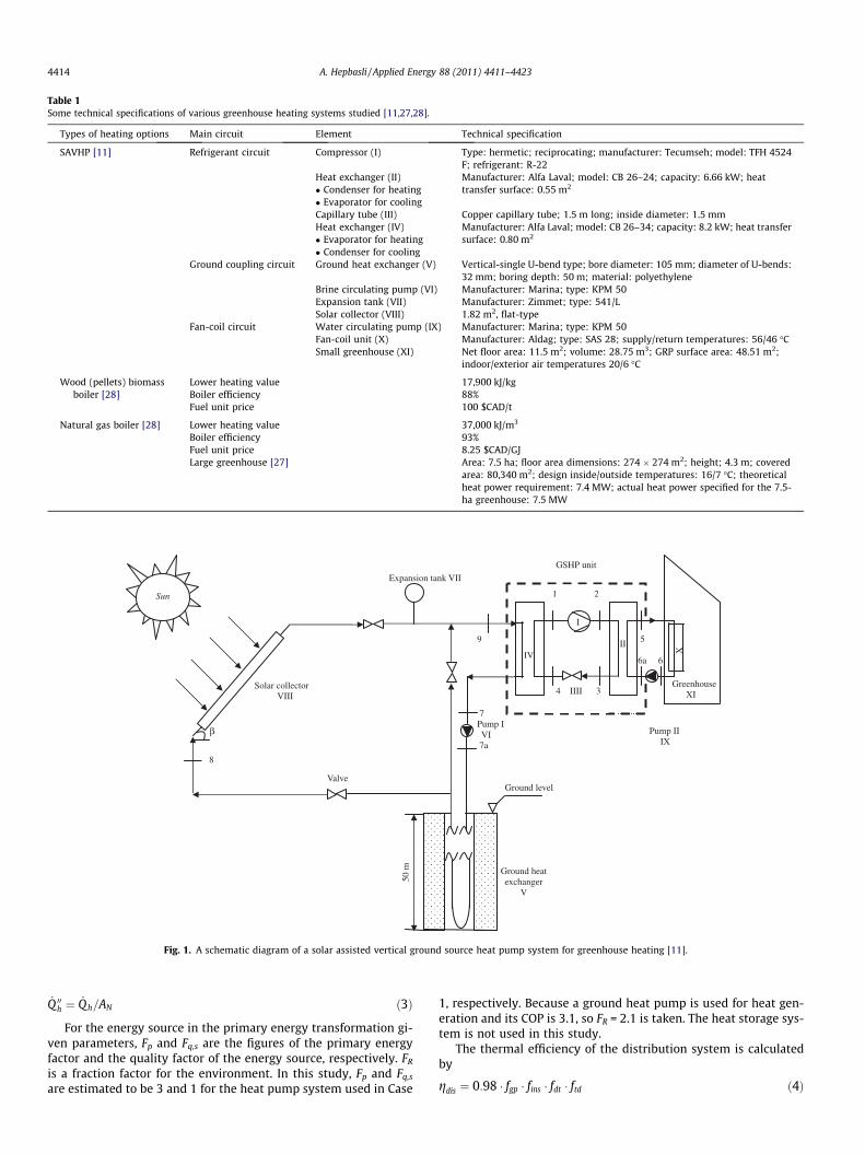
Table 1Some technical specifications of various greenhouse heating systems studied [11,27,28].
Types of heating options Main circuit Element Technical specification
SAVHP [11] Refrigerant circuit Compressor (I) Type: hermetic; reciprocating; manufacturer: Tecumseh; model: TFH 4524F; refrigerant: R-22
Heat exchanger (II) Manufacturer: Alfa Laval; model: CB 26–24; capacity: 6.66 kW; heattransfer surface: 0.55 m2� Condenser for heating
� Evaporator for coolingCapillary tube (III) Copper capillary tube; 1.5 m long; inside diameter: 1.5 mmHeat exchanger (IV) Manufacturer: Alfa Laval; model: CB 26–34; capacity: 8.2 kW; heat transfer
surface: 0.80 m2� Evaporator for heating� Condenser for cooling
Ground coupling circuit Ground heat exchanger (V) Vertical-single U-bend type; bore diameter: 105 mm; diameter of U-bends:32 mm; boring depth: 50 m; material: polyethylene
Brine circulating pump (VI) Manufacturer: Marina; type: KPM 50Expansion tank (VII) Manufacturer: Zimmet; type: 541/LSolar collector (VIII) 1.82 m2, flat-type
Fan-coil circuit Water circulating pump (IX) Manufacturer: Marina; type: KPM 50Fan-coil unit (X) Manufacturer: Aldag; type: SAS 28; supply/return temperatures: 56/46 �CSmall greenhouse (XI) Net floor area: 11.5 m2; volume: 28.75 m3; GRP surface area: 48.51 m2;
indoor/exterior air temperatures 20/6 �C
Wood (pellets) biomassboiler [28]
Lower heating value 17,900 kJ/kgBoiler efficiency 88%Fuel unit price 100 $CAD/t
Natural gas boiler [28] Lower heating value 37,000 kJ/m3
Boiler efficiency 93%Fuel unit price 8.25 $CAD/GJLarge greenhouse [27] Area: 7.5 ha; floor area dimensions: 274 � 274 m2; height; 4.3 m; covered
area: 80,340 m2; design inside/outside temperatures: 16/7 �C; theoreticalheat power requirement: 7.4 MW; actual heat power specified for the 7.5-ha greenhouse: 7.5 MW
Ground heat exchanger
V
Expansion tank VII
Greenhouse XI
X
GSHP unit
Valve
7 Pump I VI 7a
Solar collector VIII
β
50 m
Sun
IV
I
4 IIII 3
Pump II IX
II
Ground level
1 2
5
6a 6
8
9
Fig. 1. A schematic diagram of a solar assisted vertical ground source heat pump system for greenhouse heating [11].
4414 A. Hepbasli / Applied Energy 88 (2011) 4411–4423
_Q 00h ¼ _Q h=AN ð3Þ
For the energy source in the primary energy transformation gi-ven parameters, Fp and Fq,s are the figures of the primary energyfactor and the quality factor of the energy source, respectively. FR
is a fraction factor for the environment. In this study, Fp and Fq,s
are estimated to be 3 and 1 for the heat pump system used in Case
1, respectively. Because a ground heat pump is used for heat gen-eration and its COP is 3.1, so FR = 2.1 is taken. The heat storage sys-tem is not used in this study.
The thermal efficiency of the distribution system is calculatedby
gdis ¼ 0:98 � fgp � fins � fdt � ftd ð4Þ
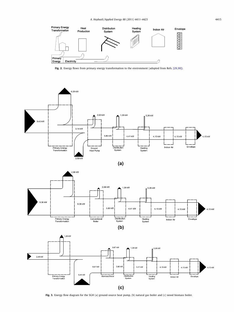
Fig. 2. Energy flows from primary energy transformation to the environment (adopted from Refs. [29,30]).
Fig. 3. Energy flow diagram for the SGH (a) ground-source heat pump, (b) natural gas boiler and (c) wood biomass boiler.
A. Hepbasli / Applied Energy 88 (2011) 4411–4423 4415
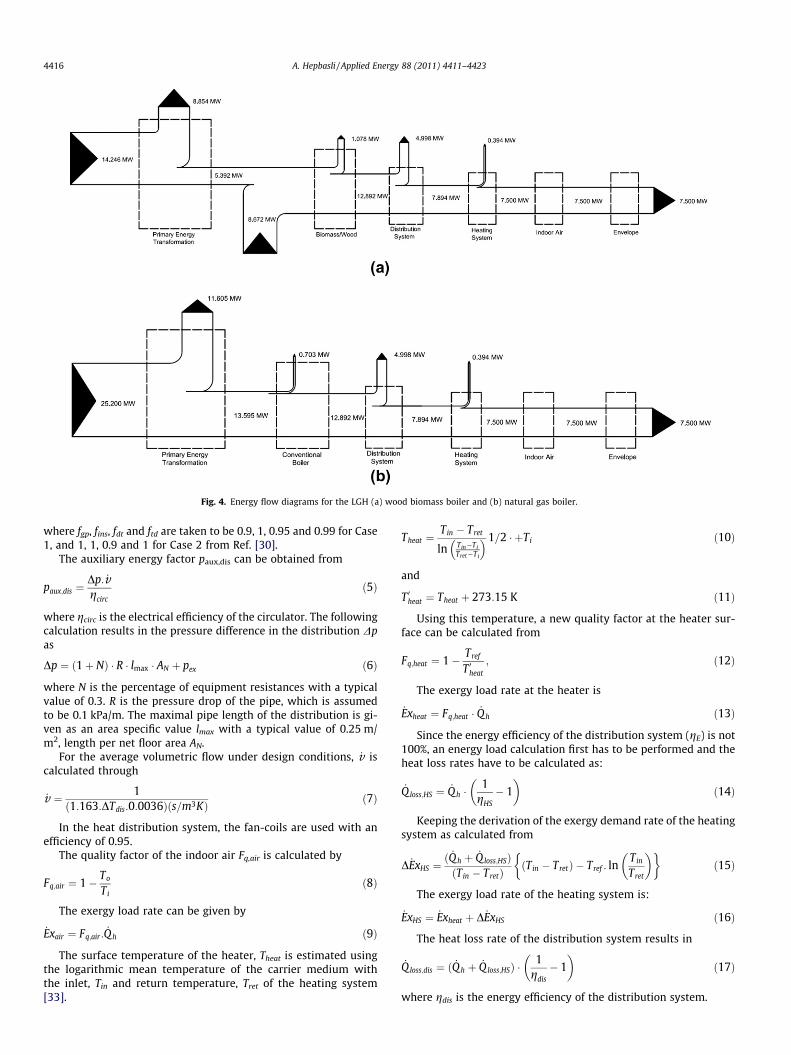
Fig. 4. Energy flow diagrams for the LGH (a) wood biomass boiler and (b) natural gas boiler.
4416 A. Hepbasli / Applied Energy 88 (2011) 4411–4423
where fgp, fins, fdt and ftd are taken to be 0.9, 1, 0.95 and 0.99 for Case1, and 1, 1, 0.9 and 1 for Case 2 from Ref. [30].
The auxiliary energy factor paux,dis can be obtained from
paux;dis ¼Dp: _vgcirc
ð5Þ
where gcirc is the electrical efficiency of the circulator. The followingcalculation results in the pressure difference in the distribution Dpas
Dp ¼ ð1þ NÞ � R � lmax � AN þ pex ð6Þ
where N is the percentage of equipment resistances with a typicalvalue of 0.3. R is the pressure drop of the pipe, which is assumedto be 0.1 kPa/m. The maximal pipe length of the distribution is gi-ven as an area specific value lmax with a typical value of 0.25 m/m2, length per net floor area AN.
For the average volumetric flow under design conditions, _v iscalculated through
_v ¼ 1ð1:163:DTdis:0:0036Þðs=m3KÞ ð7Þ
In the heat distribution system, the fan-coils are used with anefficiency of 0.95.
The quality factor of the indoor air Fq,air is calculated by
Fq;air ¼ 1� To
Tið8Þ
The exergy load rate can be given by
_Exair ¼ Fq;air : _Q h ð9Þ
The surface temperature of the heater, Theat is estimated usingthe logarithmic mean temperature of the carrier medium withthe inlet, Tin and return temperature, Tret of the heating system[33].
Theat ¼Tin � Tret
ln Tin�TiTret�Ti
� �1=2 � þTi ð10Þ
and
T 0heat ¼ Theat þ 273:15 K ð11Þ
Using this temperature, a new quality factor at the heater sur-face can be calculated from
Fq;heat ¼ 1� Tref
T 0heat
; ð12Þ
The exergy load rate at the heater is
_Exheat ¼ Fq;heat � _Q h ð13Þ
Since the energy efficiency of the distribution system (gE) is not100%, an energy load calculation first has to be performed and theheat loss rates have to be calculated as:
_Qloss;HS ¼ _Qh �1
gHS� 1
� �ð14Þ
Keeping the derivation of the exergy demand rate of the heatingsystem as calculated from
D _ExHS ¼ð _Q h þ _Q loss;HSÞðTin � TretÞ
ðTin � TretÞ � Tref : lnTin
Tret
� �� �ð15Þ
The exergy load rate of the heating system is:
_ExHS ¼ _Exheat þ D _ExHS ð16Þ
The heat loss rate of the distribution system results in
_Qloss;dis ¼ ð _Q h þ _Q loss;HSÞ �1
gdis� 1
� �ð17Þ
where gdis is the energy efficiency of the distribution system.
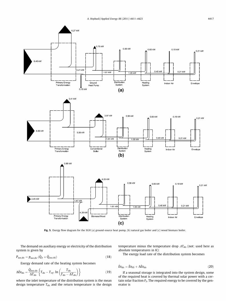
Fig. 5. Exergy flow diagram for the SGH (a) ground-source heat pump, (b) natural gas boiler and (c) wood biomass boiler.
A. Hepbasli / Applied Energy 88 (2011) 4411–4423 4417
The demand on auxiliary energy or electricity of the distributionsystem is given by
Paux;dis ¼ paux;dis:ð _Q h þ _Q loss:HSÞ ð18Þ
Exergy demand rate of the heating system becomes
D _Exdis ¼_Qloss;dis
DTdisTdis � Tref : ln
Tdis
Tdis � DTdis
� �� �ð19Þ
where the inlet temperature of the distribution system is the meandesign temperature Tdis and the return temperature is the design
temperature minus the temperature drop DTdis (not: used here asabsolute temperatures in K):
The exergy load rate of the distribution system becomes
_Exdis ¼ _ExHS þ D _Exdis ð20Þ
If a seasonal storage is integrated into the system design, someof the required heat is covered by thermal solar power with a cer-tain solar fraction FS. The required energy to be covered by the gen-erator is

Fig. 6. Exergy flow diagrams for the LGH (a) Wood biomass boiler and (b) Natural gas boiler.
4418 A. Hepbasli / Applied Energy 88 (2011) 4411–4423
_Q Ge ¼ ð _Qh þ _Qloss;HS þ _Q loss;disÞ � ð1� FSÞ �1
gGeð21Þ
The demand rate on auxiliary energy of the generation systemto drive pumps and fans is:
Paux;Ge ¼ paux;Ge:ð _Q h þ _Q loss;HS þ _Q loss;disÞ ð22Þ
The exergy load rate of the generation is calculated through
_ExGe ¼ _Q Ge:Fq;dis ð23Þ
As a second step, the exergy load rate of other greenhouse ser-vice appliances, such as lighting, ventilation, are taken into consid-eration and, in this case, named ‘‘plant’’.
_Explant ¼ ðPl þ PV Þ:Fq;el ð24Þ
The overall energy and exergy load rates of the greenhouse areexpressed in the required primary energy and exergy input rates.For the fossil or non-renewable part of the primary energy, the re-sult becomes
_Ep;tot ¼ _Q Ge � FP þ ðPl þ PV þ Paux;Ge þ Paux;dis þ Paux;HSÞ � Fp;el ð25Þ
If the generation utilizes a renewable energy source or extractsheat from the environment, as heat pumps do, the additionalrenewable energy load rate is:
_ER ¼ _Q Ge � FR þ _Eenv ð26Þ
The total exergy load rate of the greenhouse becomes
_Extot ¼ _Q Ge � Fp � Fq;s þ ðPl þ PV þ Paux;Ge þ Paux;dis þ Paux;HSÞ
� Fp;el þ _ER � Fq;R ð27Þ
This is a key parameter and can be used for a ranking in a spe-cific value, for comparing greenhouses and their efficiency andquality of exergy utilization, and for evaluating the success of theexergy optimization.
_Ex00tot ¼_Extot
AN; ð28Þ
In addition to the energy and exergy efficiencies given above,three more parameters for comparison purposes, namely sustain-ability index, energetic renewability ratio and exergetic renewabil-ity ratio, are studied as follows:
3.1. Exergy efficiency and sustainability index
Sustainable development requires not only that the sustainablesupply of clean and affordable energy resources be used, but alsothe resources should be used efficiently. Exergy methods are veryuseful tools for improving efficiency, which maximize the benefitsand usage of resources and also minimize the undesired effects(such as environmental damage). Exergy analysis can be used toimprove the efficiency and sustainability [34].
The relation between exergy efficiency (w) and the sustainabil-ity index (SI) as given in [35] can be modified to this application:
w ¼ 1� 1SI
ð29Þ

0.0
1.0
2.0
3.0
4.0
5.0
6.0
7.0
Primary Energy Transformation
Heat Production Distribution System
Heating System Indoor Air Envelope
Ener
gy L
oss
Rat
es (k
W)
Components
Case 1
Case 2
Case 3
0.0
1.0
2.0
3.0
4.0
5.0
6.0
7.0
Primary Energy Transformation
Heat Production Distribution System
Heating System Indoor Air Envelope
Exer
gy L
oss
Rat
es (k
W)
Components
Case 1
Case 2
Case 3
(a)
(b)Fig. 7. Variation of energy (a) and exergy (b) loss rates through components for the SGH (Case 1: ground-source heat pump, Case 2: natural gas boiler and Case 3: woodbiomass boiler).
0.0
2.0
4.0
6.0
8.0
10.0
12.0
Primary Energy Transformation
Heat Production Distribution System
Heating System Indoor Air Envelope
Ener
gy L
oss
Rat
es (M
W)
Components
Case 1Case 2
0.0
2.0
4.0
6.0
8.0
10.0
12.0
Primary Energy Transformation
Heat Production Distribution System
Heating System Indoor Air Envelope
Exer
gy L
oss
Rat
es (M
W)
Components
Case 1
Case 2
(a)
(b)Fig. 8. Variation of energy (a) and exergy (b) loss rates through components for the LGH (Case 1: wood biomass boiler and Case 2: natural gas boiler).
A. Hepbasli / Applied Energy 88 (2011) 4411–4423 4419
(a)
(b)
(Case 1: Ground-source heat pump, Case 2: Natural gas boiler and Case 3: Wood biomass boiler)
0.00.51.01.52.02.53.03.54.04.55.0
-10 -5 0 5 10 15
Exer
gy E
ffici
ency
(%)
Reference Temperature (ºC)
Case 1
Case 2
(Case 1: Wood biomass boiler and Case 2: Natural gas boiler)
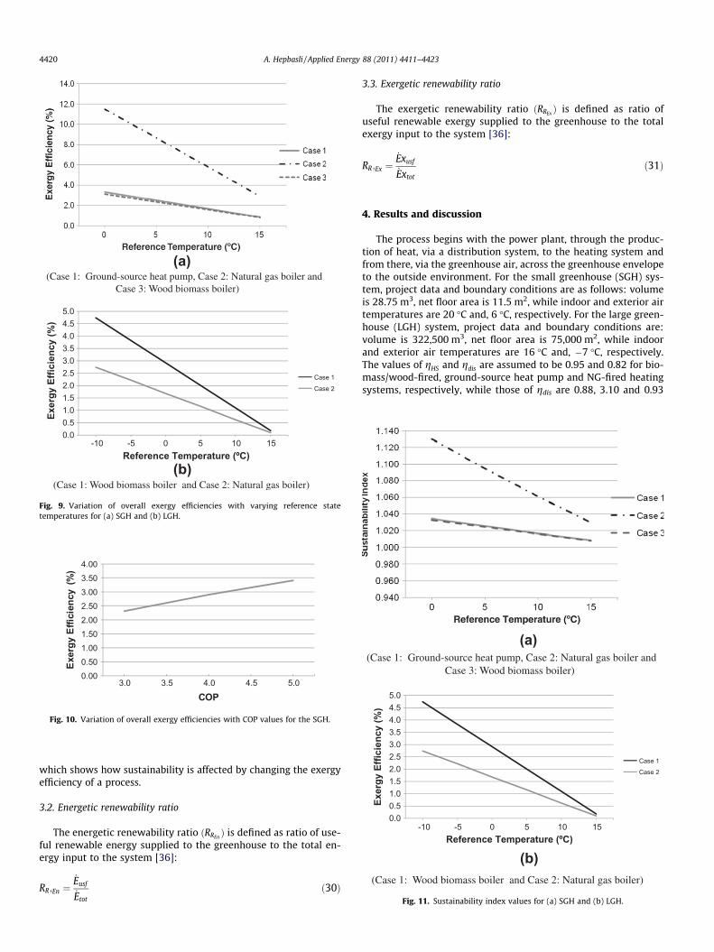
Fig. 9. Variation of overall exergy efficiencies with varying reference statetemperatures for (a) SGH and (b) LGH.
0.000.501.001.502.002.503.003.504.00
3.0 3.5 4.0 4.5 5.0
Exer
gy E
ffici
ency
(%
)
COP
Fig. 10. Variation of overall exergy efficiencies with COP values for the SGH.
(a) (Case 1: Ground-source heat pump, Case 2: Natural gas boiler and Case 3: Wood biomass boiler)
0.00.51.01.52.02.53.03.54.04.55.0
-10 -5 0 5 10 15
Exer
gy E
ffici
ency
(%)
Reference Temperature (ºC)
Case 1
Case 2
(b) (Case 1: Wood biomass boiler and Case 2: Natural gas boiler)
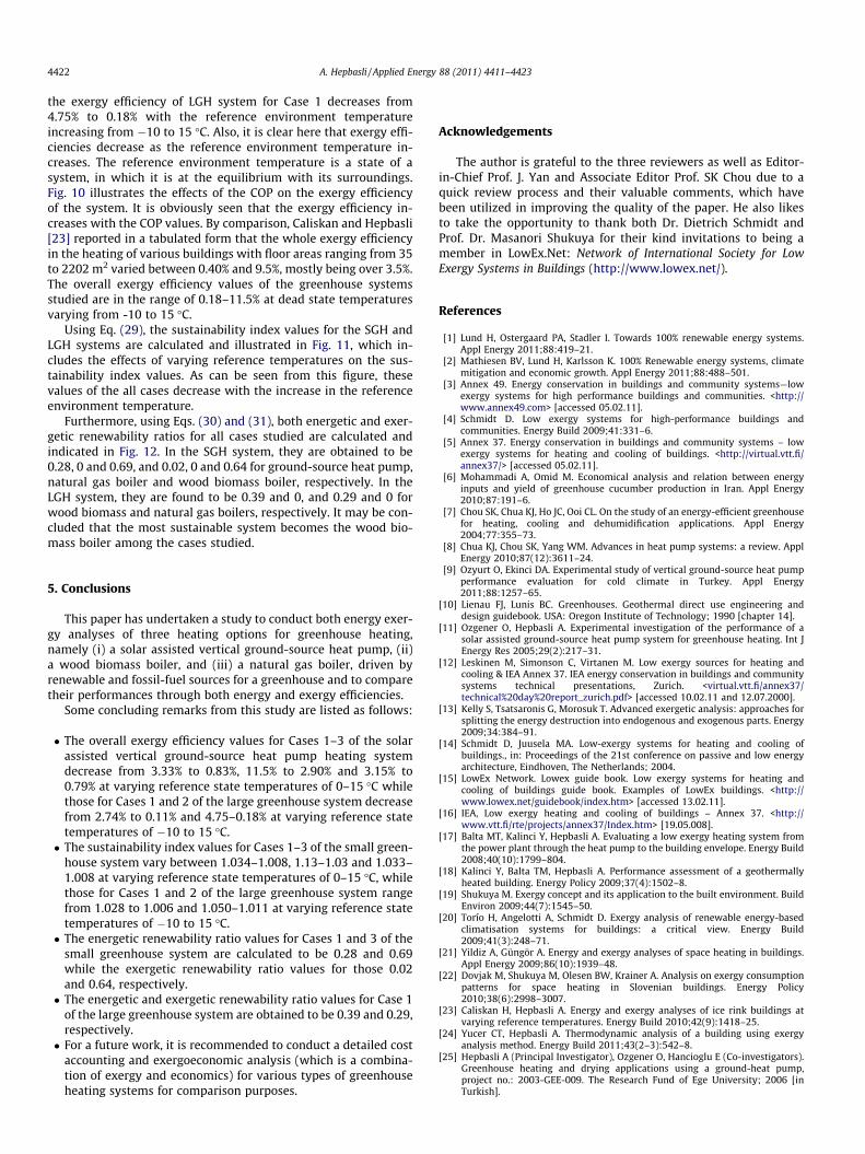
Fig. 11. Sustainability index values for (a) SGH and (b) LGH.
4420 A. Hepbasli / Applied Energy 88 (2011) 4411–4423
which shows how sustainability is affected by changing the exergyefficiency of a process.
3.2. Energetic renewability ratio
The energetic renewability ratio ðRREn Þ is defined as ratio of use-ful renewable energy supplied to the greenhouse to the total en-ergy input to the system [36]:
RR;En ¼_Eusf
_Etot
ð30Þ
3.3. Exergetic renewability ratio
The exergetic renewability ratio ðRREx Þ is defined as ratio ofuseful renewable exergy supplied to the greenhouse to the totalexergy input to the system [36]:
RR;Ex ¼_Exusf
_Extot
ð31Þ
4. Results and discussion
The process begins with the power plant, through the produc-tion of heat, via a distribution system, to the heating system andfrom there, via the greenhouse air, across the greenhouse envelopeto the outside environment. For the small greenhouse (SGH) sys-tem, project data and boundary conditions are as follows: volumeis 28.75 m3, net floor area is 11.5 m2, while indoor and exterior airtemperatures are 20 �C and, 6 �C, respectively. For the large green-house (LGH) system, project data and boundary conditions are:volume is 322,500 m3, net floor area is 75,000 m2, while indoorand exterior air temperatures are 16 �C and, �7 �C, respectively.The values of gHS and gdis are assumed to be 0.95 and 0.82 for bio-mass/wood-fired, ground-source heat pump and NG-fired heatingsystems, respectively, while those of gdis are 0.88, 3.10 and 0.93

A. Hepbasli / Applied Energy 88 (2011) 4411–4423 4421
and those of Fq,el are 1.0, 0.9 and 1.0 for the same systems consid-ered, respectively. The value of Fs is taken to be zero.
In this study, both the actual data and the data taken from theliterature are utilized to analyze and evaluate the performance oftwo types of greenhouses considered. The heat losses are basedon the measured values from the author’s common studies andthe literature reported by other investigators. In this regard, deter-mination of the heat losses, which is the first step in this analysis,may be done in more detail using the relevant relations given inthe literature. According to the data utilized, the heat demand ratesare 4.15 kW and 7.5 MW for the SGH and LGH, while their specificheat demand rates calculated from Eq. (3) are 360.87 W/m2 and100 W/m2, respectively.
Figs. 3 and 4 show energy flow diagrams for the SGH and LGH,respectively. For the considered cases, the SGH system requiresprimary energy rates of 13.02 kW, 9.36 kW and 7.93 kW in orderto supply a total of 4.15 kW to the SGH. On the other hand, the pri-mary energy rates for the LGH system of Cases 1 and 2 are calcu-lated as 22.918 MW and 25.200 MW in order to supply a total of7.500 MW to the LGH. For both of the SGH and LGH, the highestamounts of heat loss rates occur in the primary energy transforma-tion except Case 3 of the SGH. In the heat production section of theSGH system for Cases 1 and 3 and the LGH system for Case 1, anincrease in the energy flow is due to the ground heat pump andbiomass/wood, which produce 6.73 kW and 6.67 kW for the SGHsystem and 14.064 MW for the LGH system, respectively. Theexplanation for this increase is the amount of renewable environ-mental heat included in this section. The total exergy demand rate
0.0
0.2
0.4
0.6
0.8
1.0
Case 1 Case 2
Ren
ewab
ility
Rat
io
(a) (Case 1: Ground-source heat pump, Cas Case 3: Wood biomass
0.0
0.2
0.4
0.6
0.8
1.0
Case 1
Ren
ewab
ility
Rat
io
(b) (Case 1: Wood biomass boiler and Ca
Fig. 12. Renewability ratio valu
is determined based on the methodology as followed in the energydemand calculation, but using exergy analysis approach. Similarly,the same operating conditions for each component of the SGH andLGH systems in themselves are considered.
The largest exergy demand rates are calculated for the primaryenergy transformation of Case 2 for the SGH as 8.99 kW and Case 2for the LGH as 24.604 MW. Also, as can be seen in Figs. 5 and 6, thesmallest exergy demand rate is 6.88 kW for the SGH system forCase 2 and 21.187 MW for the LGH system for Case 1.
The variations of energy and exergy loss rates through compo-nents for the both systems are shown in Figs. 7 and 8. LargestThe largest energy and exergy loss rates take place in the primaryenergy transformation and heat production, as expected. On theother hand, it is clear from Figs. 5 and 6 that exergy is consumedcontinually in each component for all cases. While the flow of en-ergy leaves the building envelope, there is still a remarkableamount of energy left, but this is not true for exergy. At the refer-ence environment conditions, exergy has no potential of doingwork; so all exergy has been consumed. The exergy flow on theright side of the diagram is required to be zero. It is also investi-gated how the exergy efficiencies for the studied cases for theSGH and LGH systems considered here vary with the referencetemperature. Apparently, Fig. 9 indicates the influence of changingthe reference temperature on exergy efficiencies. In this figure, thehighest exergy efficiency values are obtained for Cases 2 and 1 forthe SGH and LGH systems, respectively. So, the exergy efficiency ofthe SGH system for Case 2 decreases from 11.55% to 2.90% with thereference environment temperature increasing from 0 to 15 �C and
Case 3
Energetic
Exergetic
e 2: Natural gas boiler and boiler)
Case 2
Energetic
Exergetic
se 2: Natural gas boiler)
es for (a) SGH and (b) LGH.
4422 A. Hepbasli / Applied Energy 88 (2011) 4411–4423
the exergy efficiency of LGH system for Case 1 decreases from4.75% to 0.18% with the reference environment temperatureincreasing from �10 to 15 �C. Also, it is clear here that exergy effi-ciencies decrease as the reference environment temperature in-creases. The reference environment temperature is a state of asystem, in which it is at the equilibrium with its surroundings.Fig. 10 illustrates the effects of the COP on the exergy efficiencyof the system. It is obviously seen that the exergy efficiency in-creases with the COP values. By comparison, Caliskan and Hepbasli[23] reported in a tabulated form that the whole exergy efficiencyin the heating of various buildings with floor areas ranging from 35to 2202 m2 varied between 0.40% and 9.5%, mostly being over 3.5%.The overall exergy efficiency values of the greenhouse systemsstudied are in the range of 0.18–11.5% at dead state temperaturesvarying from -10 to 15 �C.
Using Eq. (29), the sustainability index values for the SGH andLGH systems are calculated and illustrated in Fig. 11, which in-cludes the effects of varying reference temperatures on the sus-tainability index values. As can be seen from this figure, thesevalues of the all cases decrease with the increase in the referenceenvironment temperature.
Furthermore, using Eqs. (30) and (31), both energetic and exer-getic renewability ratios for all cases studied are calculated andindicated in Fig. 12. In the SGH system, they are obtained to be0.28, 0 and 0.69, and 0.02, 0 and 0.64 for ground-source heat pump,natural gas boiler and wood biomass boiler, respectively. In theLGH system, they are found to be 0.39 and 0, and 0.29 and 0 forwood biomass and natural gas boilers, respectively. It may be con-cluded that the most sustainable system becomes the wood bio-mass boiler among the cases studied.
5. Conclusions
This paper has undertaken a study to conduct both energy exer-gy analyses of three heating options for greenhouse heating,namely (i) a solar assisted vertical ground-source heat pump, (ii)a wood biomass boiler, and (iii) a natural gas boiler, driven byrenewable and fossil-fuel sources for a greenhouse and to comparetheir performances through both energy and exergy efficiencies.
Some concluding remarks from this study are listed as follows:
� The overall exergy efficiency values for Cases 1–3 of the solarassisted vertical ground-source heat pump heating systemdecrease from 3.33% to 0.83%, 11.5% to 2.90% and 3.15% to0.79% at varying reference state temperatures of 0–15 �C whilethose for Cases 1 and 2 of the large greenhouse system decreasefrom 2.74% to 0.11% and 4.75–0.18% at varying reference statetemperatures of �10 to 15 �C.� The sustainability index values for Cases 1–3 of the small green-
house system vary between 1.034–1.008, 1.13–1.03 and 1.033–1.008 at varying reference state temperatures of 0–15 �C, whilethose for Cases 1 and 2 of the large greenhouse system rangefrom 1.028 to 1.006 and 1.050–1.011 at varying reference statetemperatures of �10 to 15 �C.� The energetic renewability ratio values for Cases 1 and 3 of the
small greenhouse system are calculated to be 0.28 and 0.69while the exergetic renewability ratio values for those 0.02and 0.64, respectively.� The energetic and exergetic renewability ratio values for Case 1
of the large greenhouse system are obtained to be 0.39 and 0.29,respectively.� For a future work, it is recommended to conduct a detailed cost
accounting and exergoeconomic analysis (which is a combina-tion of exergy and economics) for various types of greenhouseheating systems for comparison purposes.
Acknowledgements
The author is grateful to the three reviewers as well as Editor-in-Chief Prof. J. Yan and Associate Editor Prof. SK Chou due to aquick review process and their valuable comments, which havebeen utilized in improving the quality of the paper. He also likesto take the opportunity to thank both Dr. Dietrich Schmidt andProf. Dr. Masanori Shukuya for their kind invitations to being amember in LowEx.Net: Network of International Society for LowExergy Systems in Buildings (http://www.lowex.net/).
References
[1] Lund H, Ostergaard PA, Stadler I. Towards 100% renewable energy systems.Appl Energy 2011;88:419–21.
[2] Mathiesen BV, Lund H, Karlsson K. 100% Renewable energy systems, climatemitigation and economic growth. Appl Energy 2011;88:488–501.
[3] Annex 49. Energy conservation in buildings and community systems—lowexergy systems for high performance buildings and communities. <http://www.annex49.com> [accessed 05.02.11].
[4] Schmidt D. Low exergy systems for high-performance buildings andcommunities. Energy Build 2009;41:331–6.
[5] Annex 37. Energy conservation in buildings and community systems – lowexergy systems for heating and cooling of buildings. <http://virtual.vtt.fi/annex37/> [accessed 05.02.11].
[6] Mohammadi A, Omid M. Economical analysis and relation between energyinputs and yield of greenhouse cucumber production in Iran. Appl Energy2010;87:191–6.
[7] Chou SK, Chua KJ, Ho JC, Ooi CL. On the study of an energy-efficient greenhousefor heating, cooling and dehumidification applications. Appl Energy2004;77:355–73.
[8] Chua KJ, Chou SK, Yang WM. Advances in heat pump systems: a review. ApplEnergy 2010;87(12):3611–24.
[9] Ozyurt O, Ekinci DA. Experimental study of vertical ground-source heat pumpperformance evaluation for cold climate in Turkey. Appl Energy2011;88:1257–65.
[10] Lienau FJ, Lunis BC. Greenhouses. Geothermal direct use engineering anddesign guidebook. USA: Oregon Institute of Technology; 1990 [chapter 14].
[11] Ozgener O, Hepbasli A. Experimental investigation of the performance of asolar assisted ground-source heat pump system for greenhouse heating. Int JEnergy Res 2005;29(2):217–31.
[12] Leskinen M, Simonson C, Virtanen M. Low exergy sources for heating andcooling & IEA Annex 37. IEA energy conservation in buildings and communitysystems technical presentations, Zurich. <virtual.vtt.fi/annex37/technical%20day%20report_zurich.pdf> [accessed 10.02.11 and 12.07.2000].
[13] Kelly S, Tsatsaronis G, Morosuk T. Advanced exergetic analysis: approaches forsplitting the energy destruction into endogenous and exogenous parts. Energy2009;34:384–91.
[14] Schmidt D, Juusela MA. Low-exergy systems for heating and cooling ofbuildings., in: Proceedings of the 21st conference on passive and low energyarchitecture, Eindhoven, The Netherlands; 2004.
[15] LowEx Network. Lowex guide book. Low exergy systems for heating andcooling of buildings guide book. Examples of LowEx buildings. <http://www.lowex.net/guidebook/index.htm> [accessed 13.02.11].
[16] IEA, Low exergy heating and cooling of buildings – Annex 37. <http://www.vtt.fi/rte/projects/annex37/Index.htm> [19.05.008].
[17] Balta MT, Kalinci Y, Hepbasli A. Evaluating a low exergy heating system fromthe power plant through the heat pump to the building envelope. Energy Build2008;40(10):1799–804.
[18] Kalinci Y, Balta TM, Hepbasli A. Performance assessment of a geothermallyheated building. Energy Policy 2009;37(4):1502–8.
[19] Shukuya M. Exergy concept and its application to the built environment. BuildEnviron 2009;44(7):1545–50.
[20] Torío H, Angelotti A, Schmidt D. Exergy analysis of renewable energy-basedclimatisation systems for buildings: a critical view. Energy Build2009;41(3):248–71.
[21] Yildiz A, Güngör A. Energy and exergy analyses of space heating in buildings.Appl Energy 2009;86(10):1939–48.
[22] Dovjak M, Shukuya M, Olesen BW, Krainer A. Analysis on exergy consumptionpatterns for space heating in Slovenian buildings. Energy Policy2010;38(6):2998–3007.
[23] Caliskan H, Hepbasli A. Energy and exergy analyses of ice rink buildings atvarying reference temperatures. Energy Build 2010;42(9):1418–25.
[24] Yucer CT, Hepbasli A. Thermodynamic analysis of a building using exergyanalysis method. Energy Build 2011;43(2–3):542–8.
[25] Hepbasli A (Principal Investigator), Ozgener O, Hancioglu E (Co-investigators).Greenhouse heating and drying applications using a ground-heat pump,project no.: 2003-GEE-009. The Research Fund of Ege University; 2006 [inTurkish].

A. Hepbasli / Applied Energy 88 (2011) 4411–4423 4423
[26] Ozgener O, Hepbasli A. Performance analysis of a solar assisted ground-sourceheat pump system for greenhouse heating: an experimental study. BuildEnviron 2005;40(8):1040–50.
[27] Chau J, Sowlati T, Sokhansanj S, Preto F, Melin S, Xi B. Techno-economicanalysis of wood biomass boilers for the greenhouse industry. Appl Energy2009;86:364–71.
[28] Chau J, Sowlati T, Sokhansanj S, Preto F, Melin S, Bi X. Economic sensitivity ofwood biomass utilization for greenhouse heating application. Appl Energy2009;86:616–21.
[29] Balta MT, Dincer I, Hepbasli A. Performance and sustainability assessment ofenergy options for building HVAC applications. Energy Build 2010;42(8):1320–8.
[30] Schmidt D. Design of low exergy buildings-method and a pre-design tool. Int JLow Energy Sustain Build 2003;3:1–47.
[31] LowEx. LowEx.Net. Network of international society for low exergy systems inbuildings. <http://www.lowex.org> [accessed 18.02.11].
[32] The Canada Plan Service. Greenhouse heating requirements. Plan M-6701.<http://www.cps.gov.on.ca/english/plans/E6000/6701/M-6701L.pdf>[accessed 25.02.11].
[33] Moran MJ, Shapiro HN. Fundamentals of engineering thermodynamics. 3rd ed.New York: John Wiley and Sons; 1998.
[34] Cornelissen RL. Thermodynamics and sustainable development. Ph.D. Thesis,University of Twente; 1997.
[35] Rosen MA, Dincer I, Kanoglu M. Role of exergy in increasing efficiency andsustainability and reducing environmental impact. Energy Policy2008;36:128–37.
[36] Coskun C, Oktay Z, Dincer I. New energy and exergy parameters for geothermaldistrict heating systems. Appl Therm Eng 2009;29:2235–42.