Embed Size (px)
Citation preview
International Research Journal of Engineering and Technology (IRJET) e-ISSN: 2395 -0056
Volume: 03 Issue: 08 | August -2016 www.irjet.net p-ISSN: 2395-0072
© 2016, IRJET | Impact Factor value: 4.45 | ISO 9001:2008 Certified Journal | Page 1138
A Comparative Study on Lateral Force Resisting System For
Seismic Loads
Dr.H.M. Somasekharaiah1, Mr. Madhu Sudhana Y B2, Mr. Md Muddasar Basha S3
1 Professor, Department of structural Engineering, RYM Engineering College Ballari, Karnataka, India. 2 Assistant Professor, Department of Civil Engineering, EPCET, Bengaluru, Karnataka, India.
3P.G Student, Department of structural Engineering, RYM Engineering College Ballari, Karnataka, India.
---------------------------------------------------------------------***---------------------------------------------------------------------
Abstract - From olden days we know that earthquake is disaster causing event, to overcome land crisis in cities it is essential to make earthquake resistant multi storied buildings. Any structure, to be durable and reliable, should be designed to withstand gravity loads, earthquake loads and wind loads, and able to resist all kind of temperatures, also to assimilate vibrations and absorb noises. This brought more challenges for the engineers to cater both gravity loads as well as lateral loads. Construction of multi storied buildings is more complex without using any lateral force resisting system. Provision of lateral force resisting system makes the structure earthquake resistant. The main aim of this study is to analyze the behavior of commonly used lateral force resisting systems. Here lateral force resisting systems like Shear wall, steel bracing System, masonry infill, outrigger are applied to a 20 storey symmetrical RC building, analyzed as per IS 1893 (Part 1):2002 and performances are compared. On comparing the results obtained, shear wall shows the good resistance for earthquake load compared to the other systems which is consider for the analysis.
Key Words: Bare frame, masonry strut, outrigger, bracing system, shear wall, response spectrum, ETABS 2015 etc.…
1.INTRODUCTION Buildings are subjected to two types of loads (i) vertical loads (ii) lateral load. The structural system of the building has to cater resistance for both the types of loads. It has been established that the design of multi-storey building is governed by lateral loads and it should be prime concern of the designer to provide adequately safety of the structure against lateral loads. The advances in civil engineering have already found the key to deal with this problem. Various types of resisting systems have been introduced which can resists these forces. Lateral force resisting system absorbs the lateral forces acting during the earthquake and increases the stiffness of the structure. To make the structure earthquake resistant, the provision of lateral force resisting system is essential. During the earthquake, substantial horizontal forces are acting on the structures and cause severe damages to the structural elements leads to failure of structure. To avoid the damages from horizontal forces like seismic forces and wind forces, the provision of lateral force
resisting system in the structure is must. Lateral forces can develop high stresses, produce sway movement or cause vibration, which will lead structures fail. Therefore, it is very important for the structure to have sufficient strength against vertical loads together with adequate stiffness to resist lateral loads. Hence the study on various types of lateral force resisting system is very important to know which type of system gives better performance under seismic activity. In this study, the emphasis is given on analysis of the structures having lateral force resisting systems like shear wall, steel bracing, outrigger and masonry infill.
1.1Reinforced Cement Concrete (RCC) Moment Resisting Frame
In building frame system, horizontal members (beams) with vertical members (columns) and joints of frame are resisting the earthquake forces, primarily by flexure. This system is generally preferred by architects because they are relatively unobtrusive compared to the shear wall or braced frames, but there may be poor economic risk unless special damage control measures are taken. They derive the lateral resistance from the rigidity of the connections.
1.2 Reinforced Cement Concrete Shear wall
Its consists of RCC wall instead of Masonary wall to resisting the lateral displacement and the thickness varies from 140mm to 500mm depending upon the height and the number of stores i.e. walls are placed throughout the height of the building but some walls are discontinues at the basement level to allow parking’s for the commercial buildings. Providing shear wall for the building there is no need to design specially for the beam and the columns since it is of RCC the wall itself acts as beam and column simultaneous wall. Design loads for each structural members of cantilever wall are based on the maximum available ductility. The opportunity of achieving minimum length of the wall which is to be provided by the designer. Ductility is the main factor for achieving the wall loading and later is expressed in the new ductility format. If the wall aspects ratio allows full ductility for ordinary wall, but for squatter walls for a lower value, consistent with the wall aspect ratio is adopted. Structural performance is calculated by bending, Shear and deflection.
International Research Journal of Engineering and Technology (IRJET) e-ISSN: 2395 -0056
Volume: 03 Issue: 08 | August -2016 www.irjet.net p-ISSN: 2395-0072
© 2016, IRJET | Impact Factor value: 4.45 | ISO 9001:2008 Certified Journal | Page 1139
1.3 Bracing System (BS) Braced frames are known to be efficient structural
systems for buildings under high lateral loads such as seismic or wind loadings. The bracing members are arranged in many forms, which carry solely tension, or alternatively tension and compression. Such system reduces bending moment and shear forces in the columns. Bracings hold the structure stable by transferring the loads sideways down to the ground and are used to resist lateral loads, thereby preventing sway of the structure. Bracing system is one of the retrofitting techniques and it provides an excellent approach for strengthening and stiffening of existing buildings for lateral forces. The main advantage of this system is that it increases the stiffness of the building with a minimum added weight and decreases the bending moment and shear forces in columns.
1.4 Outrigger The outrigger are the horizontal structure which are used
to resists the displacement in the tall building and to control the drift at particular storey. In general this outrigger are placed at the outside of the structure. This are design to mend overturning stiffness and strength the connection of the building to the distant column. This are used in the tall building and narrow buildings to provide resistance to the lateral forces. This are connected to the exterior column and the core to reduce the overturning and minimize the efficient of the lateral displacement at the top floors. To reduce the lateral deflection and base movement in the mulyi-storeyed structure which are subjected to lateral loads between exterior columns and outrigger battle of the central core. Damage than the long column during earth quake. The constructions of multi-storey flat slab building in level ground is better than in the construction on the sloping in ground, during earthquake the construction of building in sloping ground causes more damage to the structure and it is unsafe for the structure, the materials like burnt brick, stone.
2. OBJECTIVES OF WORK Following are the main objectives of the present
study:-
Study on linear static analysis of various lateral force resisting systems and comparing the results with conventional structure(displacement, storey drift and stiffness)
To study the lateral forces for critical zone-V and medium type II soil as per IS 1893-2002
To analyse a 20 storey frame structure with 4 different structural framing system for seismic and gravity loads, as per code 1893-2002 part I (Criteria for earthquakes resistance structure).
To analyse the earthquake response of outrigger buildings placed at different floor of the building by seismic analysis.
To analyse the structure with RC frame building with shear wall and locate effect for seismic Analysis. To analyse the structure with RC frame building with steel bracing and also for the masonary struct for effect of seismic Analysis.
Comparison of RC bare frame response of high rise building with different types of lateral force resisting systems.
B. Equivalent Diagonal Strut
Infill wall without openings The geometric and material properties of the equivalent
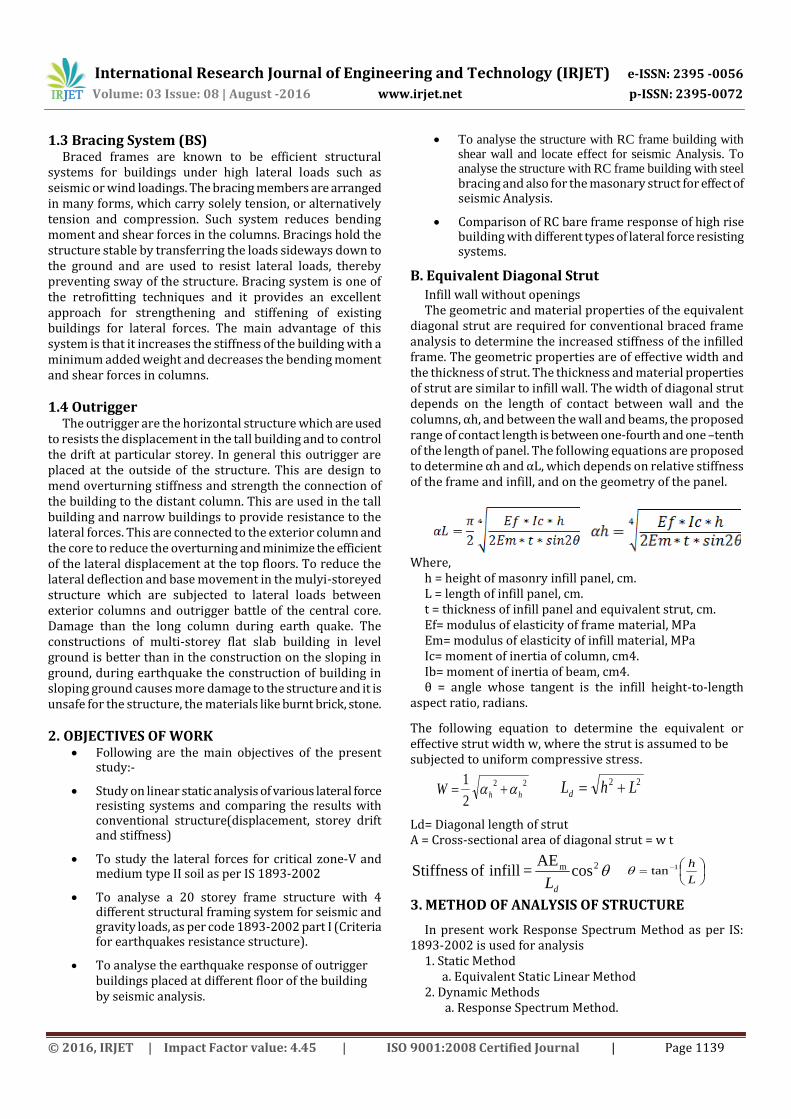
diagonal strut are required for conventional braced frame analysis to determine the increased stiffness of the infilled frame. The geometric properties are of effective width and the thickness of strut. The thickness and material properties of strut are similar to infill wall. The width of diagonal strut depends on the length of contact between wall and the columns, αh, and between the wall and beams, the proposed range of contact length is between one-fourth and one –tenth of the length of panel. The following equations are proposed to determine αh and αL, which depends on relative stiffness of the frame and infill, and on the geometry of the panel.
Where,
h = height of masonry infill panel, cm. L = length of infill panel, cm. t = thickness of infill panel and equivalent strut, cm. Ef= modulus of elasticity of frame material, MPa Em= modulus of elasticity of infill material, MPa Ic= moment of inertia of column, cm4. Ib= moment of inertia of beam, cm4. θ = angle whose tangent is the infill height-to-length
aspect ratio, radians.
The following equation to determine the equivalent or effective strut width w, where the strut is assumed to be subjected to uniform compressive stress.
22
2
1hhW
22 LhLd
Ld= Diagonal length of strut A = Cross-sectional area of diagonal strut = w t
2m cosAE
= infill of StiffnessdL
L
h1tan
3. METHOD OF ANALYSIS OF STRUCTURE
In present work Response Spectrum Method as per IS: 1893-2002 is used for analysis
1. Static Method a. Equivalent Static Linear Method 2. Dynamic Methods a. Response Spectrum Method.
International Research Journal of Engineering and Technology (IRJET) e-ISSN: 2395 -0056
Volume: 03 Issue: 08 | August -2016 www.irjet.net p-ISSN: 2395-0072
© 2016, IRJET | Impact Factor value: 4.45 | ISO 9001:2008 Certified Journal | Page 1140
3.1 Response Spectrum Method
The seismic analysis for all models buildings are carried out by response spectrum method by using IS: 1893(part-I) –2002. The other parameters used in seismic analysis are,
Severe seismic zone (V), zone factor 0.36, importance factor 1.5, 5 % damping and response reduction factor 5.0, the building frame system is special RC moment-resisting frame (SMRF) frame for all configurations and height of buildings.
As per codal provision, , if Vb/VB ratio is more than 1, dynamic results were normalized by multiplying with a base shear ratio, λ =Vb/VB , where Vb is the base shear evaluation based on time period given by empirical equation and, VB is the base shear from dynamic analysis.
4. DESCRIPTION OF MODELS A symmetrical model of 5 bays of each 6m along both
horizontal axis is considered for analysis of structure of 20 storey height. The building model is situated in seismic zone V and assuming on medium soil type. The important features of this building are shown below.
Table -1: General Data of the Building
Sl. No.
Description Data
1 Number of Stories 20
2 The building Frame system SMRF
3 Floor Height 3.15 mts
4 Type of soil Medium
6 Support Condition Fixed
Material Properties
7 Grade of Concrete M25 & M40
8 Grade of Steel Fe 500
9 Young’s modules of Concrete 5000√fck
10 Density of Concrete 25 kN/m3
11 Poisson's ratio 0.2
Structural Members
12 Column Size 300mmx900mm
13 Beam Size 300mmx600mm
14 Thickness of Slab 150mm
15 Thickness of shear wall 300mm
16 Bracing ISMB 100
17 Outrigger Size 300mmx1000mm
18 Masonary Struct Thickness 875mm
Assumed dead load intensity
16 Live load on floors 2 kN/m2
17 Floor finish 1.5kN/m2
Earthquake parameters
18 Importance factors, I 1,1.5
19 Time period, t 0.075h0.75 & (0.09h/√d)
20 Zone, V 0.36
21 Response reduction factor 5
22 Damping of the Structure 5%
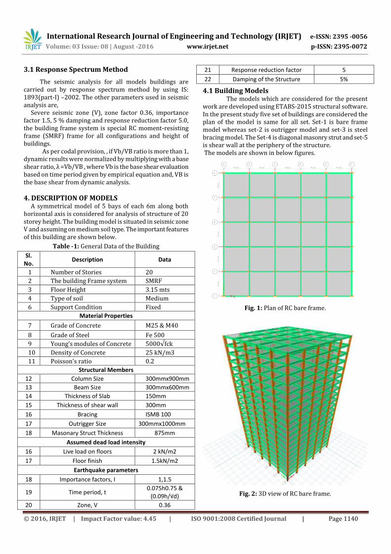
4.1 Building Models The models which are considered for the present work are developed using ETABS-2015 structural software. In the present study five set of buildings are considered the plan of the model is same for all set. Set-1 is bare frame model whereas set-2 is outrigger model and set-3 is steel bracing model. The Set-4 is diagonal masonry strut and set-5 is shear wall at the periphery of the structure. The models are shown in below figures.
Fig. 1: Plan of RC bare frame.
Fig. 2: 3D view of RC bare frame.
International Research Journal of Engineering and Technology (IRJET) e-ISSN: 2395 -0056
Volume: 03 Issue: 08 | August -2016 www.irjet.net p-ISSN: 2395-0072
© 2016, IRJET | Impact Factor value: 4.45 | ISO 9001:2008 Certified Journal | Page 1141
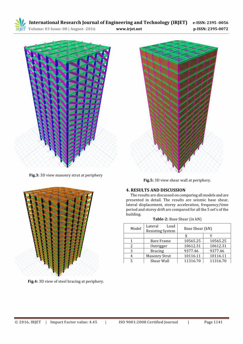
Fig.3: 3D view masonry strut at periphery
Fig.4: 3D view of steel bracing at periphery.
Fig.5: 3D view shear wall at periphery.
4. RESULTS AND DISCUSSION The results are discussed on comparing all models and are
presented in detail. The results are seismic base shear, lateral displacement, storey acceleration, frequency/time period and storey drift are compared for all the 5 set’s of the building.
Table-2: Base Shear (in kN)
Model Lateral Load Resisting System
Base Shear (kN)
X Y 1 Bare Frame 10565.25 10565.25 2 Outrigger 10612.31 10612.31 3 Bracing 9377.46 9377.46 4 Masonry Strut 10116.11 10116.11 5 Shear Wall 11316.70 11316.70
International Research Journal of Engineering and Technology (IRJET) e-ISSN: 2395 -0056
Volume: 03 Issue: 08 | August -2016 www.irjet.net p-ISSN: 2395-0072
© 2016, IRJET | Impact Factor value: 4.45 | ISO 9001:2008 Certified Journal | Page 1142
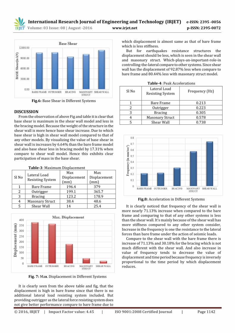
Fig.6: Base Shear in Different Systems
DISCUSSION From the observation of above Fig and table it is clear that
base shear is maximum in the shear wall model and less in the bracing model. Because the weight of the structure in the shear wall is more hence base shear increase. Due to which base shear is high in shear wall model compared to that of any other models. By visualizing the value of base shear in shear wall is increases by 6.64% than the bare frame model and also base shear less in bracing model by 17.31% when compare to shear wall model. Hence this exhibits clear participation of mass in the base shear.
Table-3: Maximum Displacement
Sl No Lateral Load Resisting System
Max Displacement (mm)
Max Displacement (mm)
1 Bare Frame 196.4 379 2 Outrigger 199.1 365.7 3 Bracing 123.2 178.9 4 Masonary Struct 38.4 48.6 5 Shear Wall 14 25.4
Fig. 7: Max. Displacement in Different Systems
It is clearly seen from the above table and fig, that the displacement is high in bare frame since that there is no additional lateral load resisting system included. But providing outrigger as the lateral force resisting system does not give better performance compare to bare frame due to
which displacement is almost same as that of bare frame which is less stiffness.
But for earthquakes resistance structures the displacement should be less, which is seen in the shear wall and masonary struct. Which-plays-an-important-role-in controlling-the-lateral compare to other systems. Since shear wall has the displacement of 92.87% less when compare to bare frame and 80.44% less with masonary struct model.
Table-4: Peak Accelerations
Sl No Lateral Load
Resisting System Frequency (Hz)
1 Bare Frame 0.213 2 Outrigger 0.223 3 Bracing 0.305 4 Masonary Struct 0.578 5 Shear Wall 0.738
Fig.8: Acceleration in Different Systems
It is clearly noticed that frequency of the shear wall is more nearly 71.13% increase when compared to the bare frame and comparing to that of any other systems is less than the shear wall. It’s mainly because of the shear wall has more stiffness compared to any other system consider, Increase in the frequency is one the resistance to the lateral forces than bare frame under the action of seismic loads.
Compare to the shear wall with the bare frame there is increase of 71.13% and 30.18% for the bracing which is not much different with the shear wall. And also increase in value of frequency tends to decrease the value of displacement and time period because frequency is inversely proportional to the time period by which displacement reduces.
International Research Journal of Engineering and Technology (IRJET) e-ISSN: 2395 -0056
Volume: 03 Issue: 08 | August -2016 www.irjet.net p-ISSN: 2395-0072
© 2016, IRJET | Impact Factor value: 4.45 | ISO 9001:2008 Certified Journal | Page 1143
Table-5: Maximum Drift
Storey
Bare Frame
Outrigger
Bracing
Masonary Struct
Shear wall
20 1 1.07 0.7 0.416 0.147
19 1.407 1.529 0.956 0.469 0.155
18 1.877 2.043 1.239 0.512 0.163
17 2.3 2.501 1.483 0.553 0.169
16 2.644 2.87 1.684 0.588 0.175
15 2.919 3.161 1.851 0.617 0.18
14 3.15 3.401 1.996 0.64 0.185
13 3.367 3.622 2.125 0.657 0.188
12 3.586 3.839 2.241 0.67 0.191
11 3.803 4.048 2.346 0.678 0.193
10 4.007 4.23 2.444 0.683 0.194
9 4.185 4.354 2.536 0.685 0.194
8 4.339 4.364 2.623 0.684 0.193
7 4.482 4.1 2.704 0.681 0.191
6 4.626 3.107 2.781 0.676 0.189
5 4.763 3.238 2.856 0.668 0.186
4 4.839 4.38 2.916 0.66 0.178
3 4.713 4.376 2.906 0.641 0.179
2 4.052 3.023 2.686 0.836 0.461
1 2.029 1.243 1.605 1.375 1.099
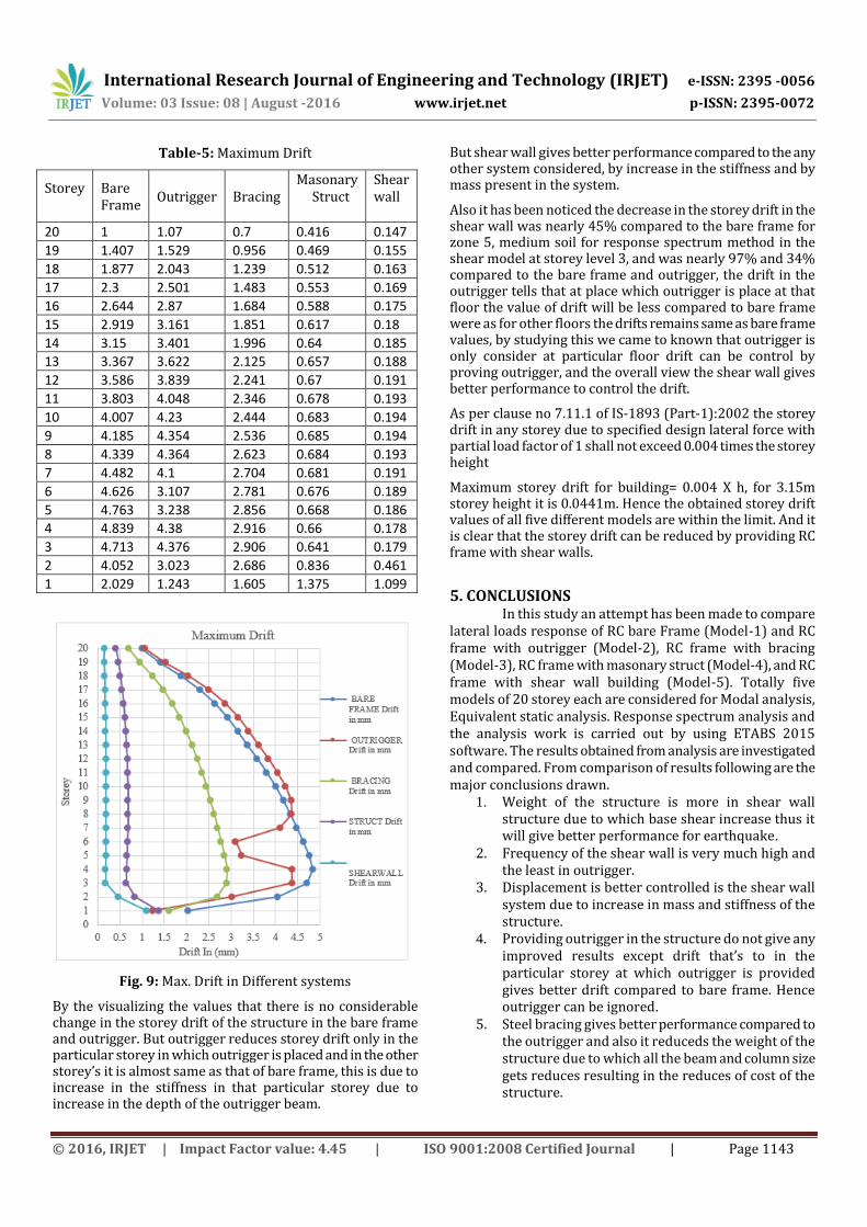
Fig. 9: Max. Drift in Different systems
By the visualizing the values that there is no considerable change in the storey drift of the structure in the bare frame and outrigger. But outrigger reduces storey drift only in the particular storey in which outrigger is placed and in the other storey’s it is almost same as that of bare frame, this is due to increase in the stiffness in that particular storey due to increase in the depth of the outrigger beam.
But shear wall gives better performance compared to the any other system considered, by increase in the stiffness and by mass present in the system.
Also it has been noticed the decrease in the storey drift in the shear wall was nearly 45% compared to the bare frame for zone 5, medium soil for response spectrum method in the shear model at storey level 3, and was nearly 97% and 34% compared to the bare frame and outrigger, the drift in the outrigger tells that at place which outrigger is place at that floor the value of drift will be less compared to bare frame were as for other floors the drifts remains same as bare frame values, by studying this we came to known that outrigger is only consider at particular floor drift can be control by proving outrigger, and the overall view the shear wall gives better performance to control the drift.
As per clause no 7.11.1 of IS-1893 (Part-1):2002 the storey drift in any storey due to specified design lateral force with partial load factor of 1 shall not exceed 0.004 times the storey height
Maximum storey drift for building= 0.004 X h, for 3.15m storey height it is 0.0441m. Hence the obtained storey drift values of all five different models are within the limit. And it is clear that the storey drift can be reduced by providing RC frame with shear walls.
5. CONCLUSIONS In this study an attempt has been made to compare
lateral loads response of RC bare Frame (Model-1) and RC frame with outrigger (Model-2), RC frame with bracing (Model-3), RC frame with masonary struct (Model-4), and RC frame with shear wall building (Model-5). Totally five models of 20 storey each are considered for Modal analysis, Equivalent static analysis. Response spectrum analysis and the analysis work is carried out by using ETABS 2015 software. The results obtained from analysis are investigated and compared. From comparison of results following are the major conclusions drawn.
1. Weight of the structure is more in shear wall structure due to which base shear increase thus it will give better performance for earthquake.
2. Frequency of the shear wall is very much high and the least in outrigger.
3. Displacement is better controlled is the shear wall system due to increase in mass and stiffness of the structure.
4. Providing outrigger in the structure do not give any improved results except drift that’s to in the particular storey at which outrigger is provided gives better drift compared to bare frame. Hence outrigger can be ignored.
5. Steel bracing gives better performance compared to the outrigger and also it reduceds the weight of the structure due to which all the beam and column size gets reduces resulting in the reduces of cost of the structure.
International Research Journal of Engineering and Technology (IRJET) e-ISSN: 2395 -0056
Volume: 03 Issue: 08 | August -2016 www.irjet.net p-ISSN: 2395-0072
© 2016, IRJET | Impact Factor value: 4.45 | ISO 9001:2008 Certified Journal | Page 1144
6. Hence providing steel bracing are better useful in lower zone where the possibility of occurrence of earthquakes is less and also in the zone where the magnitude of earthquakes cause very less effect.
7. Masonary wall and shear wall gives very good earthquakes resistance for the building due to very high stiffness. But comparing masonary struct and shear wall will produce better results
8. This is because of higher ductility in the section due reinforcement present in the shear wall, By observing all it can be concluded that providing outrigger is not useful in earthquake resisting design.
9. Steel bracing can be used in the zones where earthquake magnitude is very less
10. Shear wall provided the best earthquakes resistance design compared to the other systems which is consider for the analysis.
ACKNOWLEDGEMENT
I am thankful to my guide, Dr.H.M.Somasekharaiah, Professor, Department Civil Engineering for his constant encouragement and able guidance. Also I thank my parents, friends and others for their continuous support in making this work complete.
REFERENCES [1] A text book on Earthquake Resistant Design of Building
Structures, by author Vinod Hosur, published by WILEY (India)
[2] Earthquake resistant design of structures - Pankaj Agarwal, Manish Shrikande - PHI India]
[3] IS 1893 (part 1):2002, Criteria for earthquake resistant design of structures.
[4] IS 456:2000, Code of practice for plain and reinforced concrete.
[5] Kapil P. Wankhade(2015), This is research /review Paper on Study on Seismic Behaviour of Lateral Force Resisting System, Volume 2, Issue 5, e-ISSN: 2348 - 4470 , print-ISSN:2348-6406,752-761, International Journal of Advance Engineering and Research Development (IJAERD)
[6] Rasool.Owais(2016),Comparative Analysis between Different Commonly used Lateral Load Resisting Systems in Reinforced Concrete Buildings, Volume XVI Issue I Version I, published by Global Journal of Researches in Engineering
[7] Piyush Gupta (2016), Analysis of Various RCC Lateral Force Resisting Systems and their Comparison using ETABS, Vol. 6 Issue 4, International Journal of Latest Trends in Engineering and Technology (IJLTET).
[8] Vikas Govalkar (2014), Analysis of Bare Frame and Infilled Frame with Different Position of Shear Wall, Volume-3 Issue-3, International Journal of Recent Technology and Engineering (IJRTE).
[9] Abhijeet Baikerikar (2014), Study of Lateral Load Resisting Systems of Variable Heights in All Soil Types of High Seismic Zone, Volume: 03 Issue: 10, International Journal of Research in Engineering and Technology (IJRET).
BIOGRAPHIES
Dr.H.M.Somasekharaiah holds his PhD degree from JNTU, Ananthapura, India. He is a Professor in Department of Civil Engineering at RYMEC Ballari, Karnataka, India. He is having 30 years of academic teaching, consultancy and research experience. He is also carrying out third party quality auditing for government projects. His research interests are Composite fibers, supplementary cementitious materials, and rheological characterisation and durability studies of high performance concrete. He has published many international and national journals. He is supervising around eight PhD project.
Mr. Madhu Sudhana Y B, Assistant Professor, Department of Civil Engineering, East Point College of Engineering And Technology, Bangalore-560049, Karnataka. Email:[email protected]
Md Muddasar Basha S, M.Tech Structural Engineering student, Department of Civil Engineering, RYM Engineering College, Ballari-583101, Karnataka. Email:[email protected]