Embed Size (px)
Citation preview
International Journal of Technical Innovation in Modern
Engineering & Science (IJTIMES) Impact Factor: 3.45 (SJIF-2015), e-ISSN: 2455-2585
Volume 4, Issue 5, May-2018
IJTIMES-2018@All rights reserved 405
Outrigger and Belt Trusses as Lateral Load Resisting System for High-Rise
Buildings
Dr. Y.M.MANJUNATH1, GIRISH KG
2
1Professor, Department of Civil Engineering, NIE, MYSURU, [email protected]
2PG Scholar, Department of Civil Engineering, NIE, MYSURU, [email protected]
Abstract: Accommodating the rising population in developing countries has given rise to increased height of
buildings. Since the cost of the land is increasing everywhere, there is an affinity among builders, architects,
engineers, clients to go for vertical growth instead of horizontal growth. To facilitate the rapid galloping growth of
basic infrastructure modern cities are demanding tall structures. Since the structures are growing vertically, the issue
of lateral stability and sway has to be dealt with utmost care. Wind and Earthquake forces contribute a great impact
on building deflection. Outrigger and Belt Truss are the lateral load resisting systems adopted in high rise buildings to
reduce deflection. The use of Outrigger and Belt Truss system Plays a major role in resisting lateral loads like wind,
seismic forces in tall buildings and has been efficiently used to provide stiffness to the structure.
Keywords— half and quarter outrigger and belt trusses, storey displacement, storey drift, wind analysis, Response
spectrum method, openings
I. INTRODUCTION
The OTBT system is utilized to check the extravagant drift due to parallel forces causing detrimental effects on tall
buildings. For tall buildings situated at windy and earthquake prone areas, outrigger and belt truss system can be chosen as
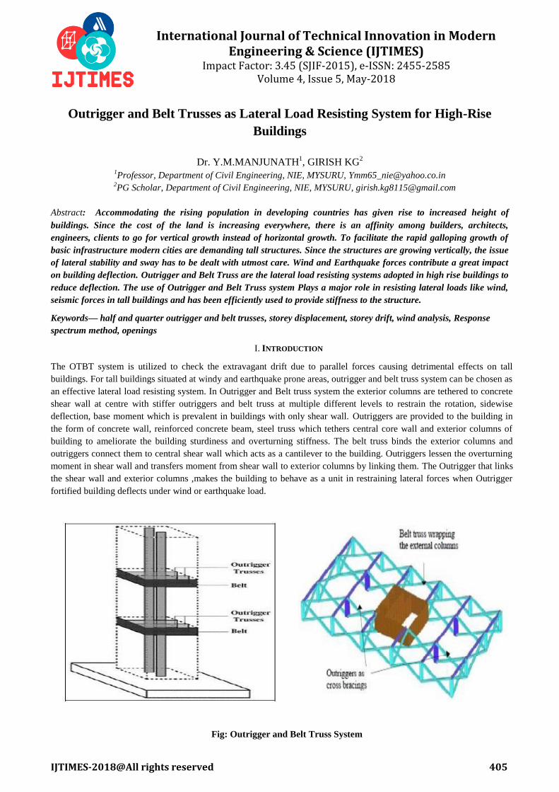
an effective lateral load resisting system. In Outrigger and Belt truss system the exterior columns are tethered to concrete
shear wall at centre with stiffer outriggers and belt truss at multiple different levels to restrain the rotation, sidewise
deflection, base moment which is prevalent in buildings with only shear wall. Outriggers are provided to the building in
the form of concrete wall, reinforced concrete beam, steel truss which tethers central core wall and exterior columns of
building to ameliorate the building sturdiness and overturning stiffness. The belt truss binds the exterior columns and
outriggers connect them to central shear wall which acts as a cantilever to the building. Outriggers lessen the overturning
moment in shear wall and transfers moment from shear wall to exterior columns by linking them. The Outrigger that links
the shear wall and exterior columns ,makes the building to behave as a unit in restraining lateral forces when Outrigger
fortified building deflects under wind or earthquake load.
Fig: Outrigger and Belt Truss System
International Journal of Technical Innovation in Modern Engineering & Science (IJTIMES) Volume 4, Issue 5, May-2018, e-ISSN: 2455-2585,Impact Factor: 3.45 (SJIF-2015)
IJTIMES-2018@All rights reserved 406
Outrigger and Belt truss system results in efficacious use of structural elements organizing the axial strength and
stiffness of peripheral columns. The outrigger which restrains the columns combats the shear wall rotation and restricts the
moment and defection in the shear wall to be smaller. The tension and compression is induced in windward and leeward
columns respectively by making it to bend as vertical cantilever thereby increasing effective depth of the structure. The
central shear wall provides resistance to building against shear.
The Outrigger and Belt truss system improves the bending stiffness of the building. Belt trusses bind the exterior
columns of the building and vehemently checks the lateral deflection of building. Belt trusses are provided with outriggers
to gather surplus axial stiffness of the Columns, thereby increasing their stiffness against torsion. One of the major
problems affecting the efficient functioning of high rise building is the shortening of column. The belt trusses minimize
the differential elongation and column shortening and are very beneficial in checking the settlement of columns. The
performance of Outrigger and Belt truss system can be affected by numerous parameters like type of high rise building,
depth of Outrigger and Belt truss system, position of Outrigger and Belt truss system, building geometry. The Outrigger
and Belt truss system vehemently checks inter storey drift and displacement at the uppermost storey of the building. Tall
buildings are fragile to lateral loads and utmost care should be taken to tackle them. Top lateral drift is a key thing in the
design of tall buildings.
. OBJECTIVES AND SCOPE OF PRESENT STUDY
The main objective of the present analytical study is to investigate the effectiveness of outrigger and belt truss system as
lateral load resisting systems and to find out their effective location in Building consisting of central shear wall with
openings. Using structural software outrigger and belt truss system with openings were modelled and basic parameters
like storey displacement and storey drift were observed. The Half and Quarter outrigger and Belt truss system were also
modelled and analyzed against wind and seismic loads to check their performance and effective position in the building.
The openings were provisioned in Outrigger and belt trusses in percentage of wall area to know the maximum percentage
of openings that can be provided for access, air keeping building deflection within the maximum allowable deflection
limit mentioned in the code.
II. STRUCTURAL DETAILS AND MATERIAL PROPERTIES
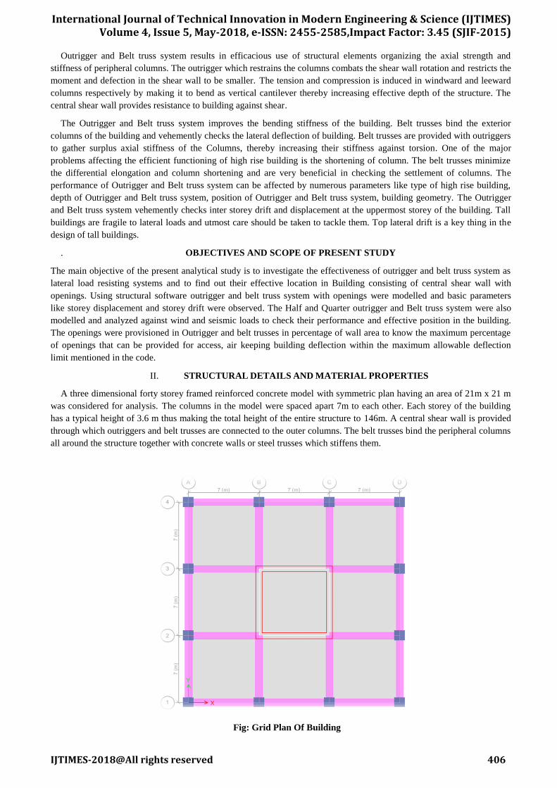
A three dimensional forty storey framed reinforced concrete model with symmetric plan having an area of 21m x 21 m
was considered for analysis. The columns in the model were spaced apart 7m to each other. Each storey of the building
has a typical height of 3.6 m thus making the total height of the entire structure to 146m. A central shear wall is provided
through which outriggers and belt trusses are connected to the outer columns. The belt trusses bind the peripheral columns
all around the structure together with concrete walls or steel trusses which stiffens them.
Fig: Grid Plan Of Building
International Journal of Technical Innovation in Modern Engineering & Science (IJTIMES) Volume 4, Issue 5, May-2018, e-ISSN: 2455-2585,Impact Factor: 3.45 (SJIF-2015)
IJTIMES-2018@All rights reserved 407
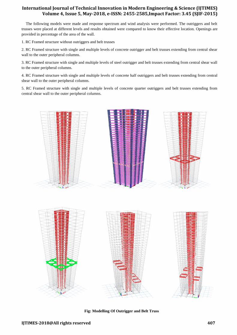
The following models were made and response spectrum and wind analysis were performed. The outriggers and belt
trusses were placed at different levels and results obtained were compared to know their effective location. Openings are
provided in percentage of the area of the wall.
1. RC Framed structure without outriggers and belt trusses
2. RC Framed structure with single and multiple levels of concrete outrigger and belt trusses extending from central shear
wall to the outer peripheral columns.
3. RC Framed structure with single and multiple levels of steel outrigger and belt trusses extending from central shear wall
to the outer peripheral columns.
4. RC Framed structure with single and multiple levels of concrete half outriggers and belt trusses extending from central
shear wall to the outer peripheral columns.
5. RC Framed structure with single and multiple levels of concrete quarter outriggers and belt trusses extending from
central shear wall to the outer peripheral columns.
Fig: Modelling Of Outrigger and Belt Truss
International Journal of Technical Innovation in Modern Engineering & Science (IJTIMES) Volume 4, Issue 5, May-2018, e-ISSN: 2455-2585,Impact Factor: 3.45 (SJIF-2015)
IJTIMES-2018@All rights reserved 408
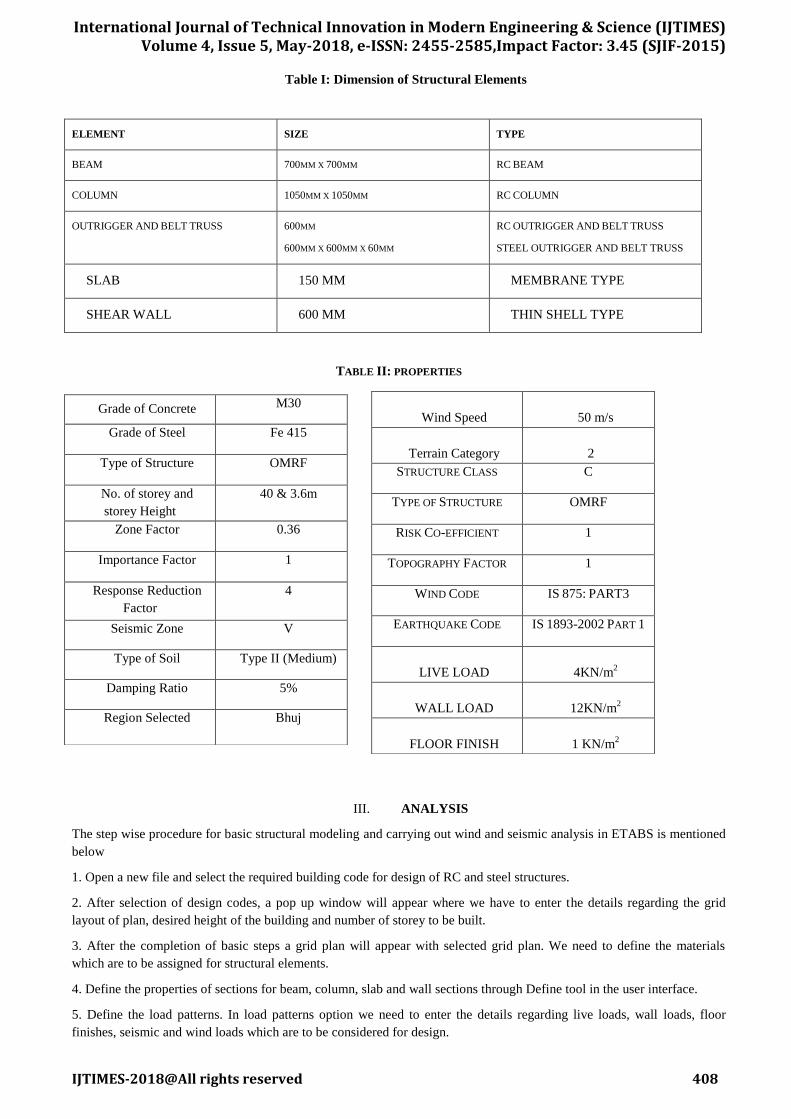
Table I: Dimension of Structural Elements
ELEMENT SIZE TYPE
BEAM 700MM X 700MM RC BEAM
COLUMN 1050MM X 1050MM RC COLUMN
OUTRIGGER AND BELT TRUSS 600MM
600MM X 600MM X 60MM
RC OUTRIGGER AND BELT TRUSS
STEEL OUTRIGGER AND BELT TRUSS
SLAB 150 MM MEMBRANE TYPE
SHEAR WALL 600 MM THIN SHELL TYPE
TABLE II: PROPERTIES
III. ANALYSIS
The step wise procedure for basic structural modeling and carrying out wind and seismic analysis in ETABS is mentioned
below
1. Open a new file and select the required building code for design of RC and steel structures.
2. After selection of design codes, a pop up window will appear where we have to enter the details regarding the grid
layout of plan, desired height of the building and number of storey to be built.
3. After the completion of basic steps a grid plan will appear with selected grid plan. We need to define the materials
which are to be assigned for structural elements.
4. Define the properties of sections for beam, column, slab and wall sections through Define tool in the user interface.
5. Define the load patterns. In load patterns option we need to enter the details regarding live loads, wall loads, floor
finishes, seismic and wind loads which are to be considered for design.
Grade of Concrete M30
Grade of Steel Fe 415
Type of Structure OMRF
No. of storey and
storey Height
40 & 3.6m
Zone Factor 0.36
Importance Factor 1
Response Reduction
Factor
4
Seismic Zone V
Type of Soil Type II (Medium)
Damping Ratio 5%
Region Selected Bhuj
Wind Speed
50 m/s
Terrain Category
2
STRUCTURE CLASS C
TYPE OF STRUCTURE OMRF
RISK CO-EFFICIENT 1
TOPOGRAPHY FACTOR 1
WIND CODE IS 875: PART3
EARTHQUAKE CODE IS 1893-2002 PART 1
LIVE LOAD
4KN/m2
WALL LOAD
12KN/m2
FLOOR FINISH
1 KN/m2
International Journal of Technical Innovation in Modern Engineering & Science (IJTIMES) Volume 4, Issue 5, May-2018, e-ISSN: 2455-2585,Impact Factor: 3.45 (SJIF-2015)
IJTIMES-2018@All rights reserved 409
6. Define load combinations. In the earlier versions of ETABS we had to enter the load combinations manually but with
the recent updates, it will automatically consider the load combinations according to the building design code we have
selected. We only need to select the default code for design of RC and steel structure.
7. Check the load cases and combinations after assigning load patterns.
8. Draw columns. Beams, slabs and other structural elements in the grid plan.
9. Selects all the grid points at the base and provide fixed support. Define floor diaphragm and assign it to the building.
10. With the completion of basic modeling check it for any errors by Check model tool provided in the user interface. At
the end analyze the building by run analysis.
11. For the seismic analysis of model, response spectrum must be defined as a function and have to be added to the load
cases list. By selecting default load combination, ETABS will automatically consider seismic load combinations.
12. For wind load analysis, the basic parameters mentioned in the above table have to be defined and assigned to the
model. By selecting default load combinations, ETABS will automatically consider wind load combinations.
IV. RESULTS AND DISCUSSION
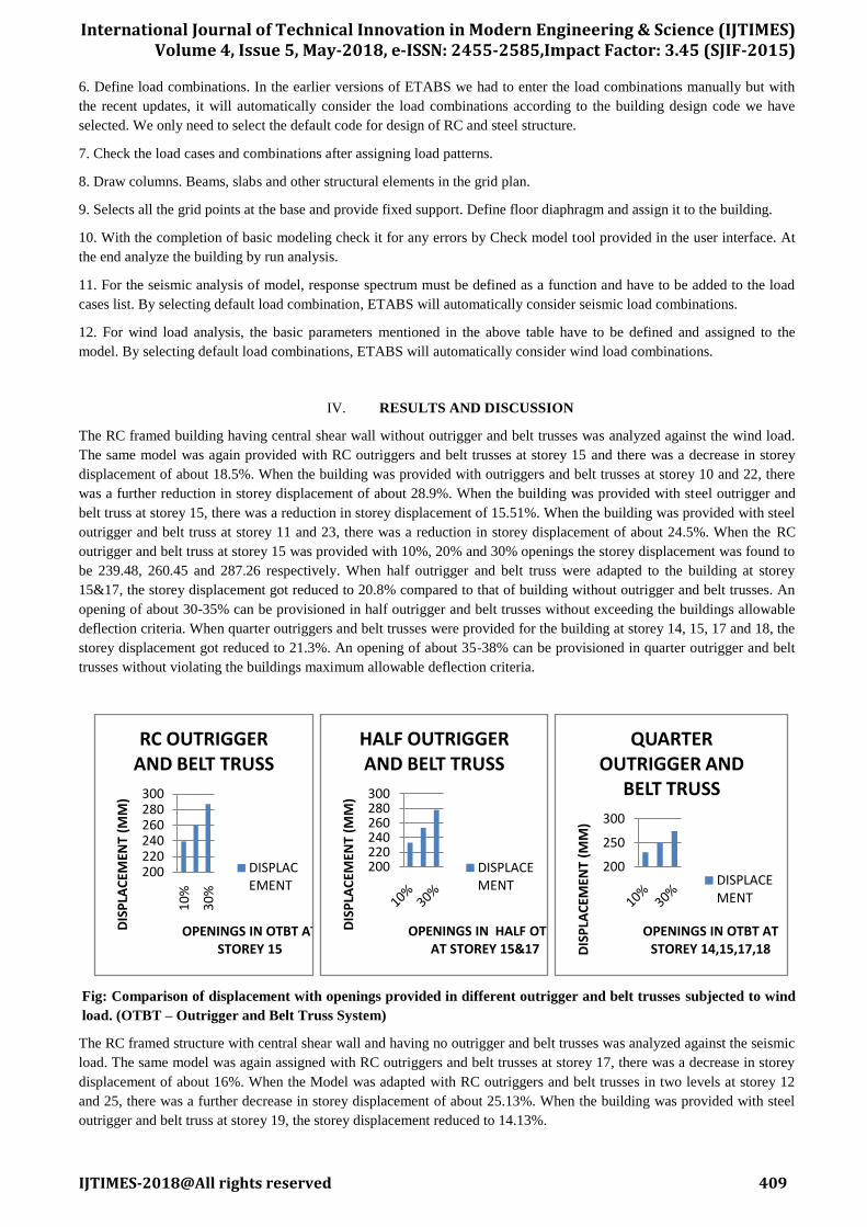
The RC framed building having central shear wall without outrigger and belt trusses was analyzed against the wind load.
The same model was again provided with RC outriggers and belt trusses at storey 15 and there was a decrease in storey
displacement of about 18.5%. When the building was provided with outriggers and belt trusses at storey 10 and 22, there
was a further reduction in storey displacement of about 28.9%. When the building was provided with steel outrigger and
belt truss at storey 15, there was a reduction in storey displacement of 15.51%. When the building was provided with steel
outrigger and belt truss at storey 11 and 23, there was a reduction in storey displacement of about 24.5%. When the RC
outrigger and belt truss at storey 15 was provided with 10%, 20% and 30% openings the storey displacement was found to
be 239.48, 260.45 and 287.26 respectively. When half outrigger and belt truss were adapted to the building at storey
15&17, the storey displacement got reduced to 20.8% compared to that of building without outrigger and belt trusses. An
opening of about 30-35% can be provisioned in half outrigger and belt trusses without exceeding the buildings allowable
deflection criteria. When quarter outriggers and belt trusses were provided for the building at storey 14, 15, 17 and 18, the
storey displacement got reduced to 21.3%. An opening of about 35-38% can be provisioned in quarter outrigger and belt
trusses without violating the buildings maximum allowable deflection criteria.
Fig: Comparison of displacement with openings provided in different outrigger and belt trusses subjected to wind
load. (OTBT – Outrigger and Belt Truss System)
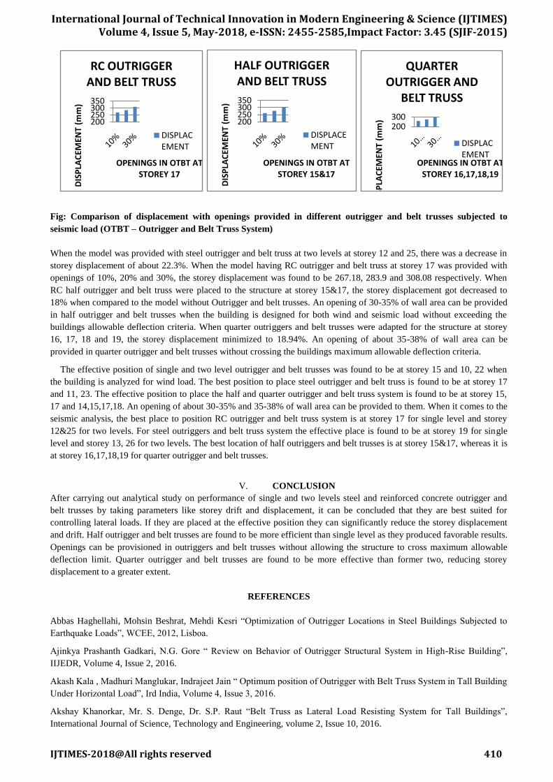
The RC framed structure with central shear wall and having no outrigger and belt trusses was analyzed against the seismic
load. The same model was again assigned with RC outriggers and belt trusses at storey 17, there was a decrease in storey
displacement of about 16%. When the Model was adapted with RC outriggers and belt trusses in two levels at storey 12
and 25, there was a further decrease in storey displacement of about 25.13%. When the building was provided with steel
outrigger and belt truss at storey 19, the storey displacement reduced to 14.13%.
200220240260280300
10%
30%
DIS
PLA
CEM
ENT
(MM
)
OPENINGS IN OTBT AT STOREY 15
RC OUTRIGGER AND BELT TRUSS
DISPLACEMENT
200220240260280300
DIS
PLA
CEM
ENT
(MM
)
OPENINGS IN HALF OTBT AT STOREY 15&17
HALF OUTRIGGER AND BELT TRUSS
DISPLACEMENT
200
250
300
DIS
PLA
CEM
ENT
(MM
)
OPENINGS IN OTBT AT STOREY 14,15,17,18
QUARTER OUTRIGGER AND
BELT TRUSS
DISPLACEMENT
International Journal of Technical Innovation in Modern Engineering & Science (IJTIMES) Volume 4, Issue 5, May-2018, e-ISSN: 2455-2585,Impact Factor: 3.45 (SJIF-2015)
IJTIMES-2018@All rights reserved 410
Fig: Comparison of displacement with openings provided in different outrigger and belt trusses subjected to
seismic load (OTBT – Outrigger and Belt Truss System)
When the model was provided with steel outrigger and belt truss at two levels at storey 12 and 25, there was a decrease in
storey displacement of about 22.3%. When the model having RC outrigger and belt truss at storey 17 was provided with
openings of 10%, 20% and 30%, the storey displacement was found to be 267.18, 283.9 and 308.08 respectively. When
RC half outrigger and belt truss were placed to the structure at storey 15&17, the storey displacement got decreased to
18% when compared to the model without Outrigger and belt trusses. An opening of 30-35% of wall area can be provided
in half outrigger and belt trusses when the building is designed for both wind and seismic load without exceeding the
buildings allowable deflection criteria. When quarter outriggers and belt trusses were adapted for the structure at storey
16, 17, 18 and 19, the storey displacement minimized to 18.94%. An opening of about 35-38% of wall area can be
provided in quarter outrigger and belt trusses without crossing the buildings maximum allowable deflection criteria.
The effective position of single and two level outrigger and belt trusses was found to be at storey 15 and 10, 22 when
the building is analyzed for wind load. The best position to place steel outrigger and belt truss is found to be at storey 17
and 11, 23. The effective position to place the half and quarter outrigger and belt truss system is found to be at storey 15,
17 and 14,15,17,18. An opening of about 30-35% and 35-38% of wall area can be provided to them. When it comes to the
seismic analysis, the best place to position RC outrigger and belt truss system is at storey 17 for single level and storey
12&25 for two levels. For steel outriggers and belt truss system the effective place is found to be at storey 19 for single
level and storey 13, 26 for two levels. The best location of half outriggers and belt trusses is at storey 15&17, whereas it is
at storey 16,17,18,19 for quarter outrigger and belt trusses.
V. CONCLUSION
After carrying out analytical study on performance of single and two levels steel and reinforced concrete outrigger and
belt trusses by taking parameters like storey drift and displacement, it can be concluded that they are best suited for
controlling lateral loads. If they are placed at the effective position they can significantly reduce the storey displacement
and drift. Half outrigger and belt trusses are found to be more efficient than single level as they produced favorable results.
Openings can be provisioned in outriggers and belt trusses without allowing the structure to cross maximum allowable
deflection limit. Quarter outrigger and belt trusses are found to be more effective than former two, reducing storey
displacement to a greater extent.
REFERENCES
Abbas Haghellahi, Mohsin Beshrat, Mehdi Kesri “Optimization of Outrigger Locations in Steel Buildings Subjected to
Earthquake Loads”, WCEE, 2012, Lisboa.
Ajinkya Prashanth Gadkari, N.G. Gore “ Review on Behavior of Outrigger Structural System in High-Rise Building”,
IIJEDR, Volume 4, Issue 2, 2016.
Akash Kala , Madhuri Manglukar, Indrajeet Jain “ Optimum position of Outrigger with Belt Truss System in Tall Building
Under Horizontal Load”, Ird India, Volume 4, Issue 3, 2016.
Akshay Khanorkar, Mr. S. Denge, Dr. S.P. Raut “Belt Truss as Lateral Load Resisting System for Tall Buildings”,
International Journal of Science, Technology and Engineering, volume 2, Issue 10, 2016.
200250300350
DIS
PLA
CEM
ENT
(mm
)
OPENINGS IN OTBT AT STOREY 17
RC OUTRIGGER AND BELT TRUSS
DISPLACEMENT
200250300350
DIS
PLA
CEM
ENT
(mm
)
OPENINGS IN OTBT AT STOREY 15&17
HALF OUTRIGGER AND BELT TRUSS
DISPLACEMENT
200300
DIS
PLA
CEM
ENT
(mm
)
OPENINGS IN OTBT AT STOREY 16,17,18,19
QUARTER OUTRIGGER AND
BELT TRUSS
DISPLACEMENT

International Journal of Technical Innovation in Modern Engineering & Science (IJTIMES) Volume 4, Issue 5, May-2018, e-ISSN: 2455-2585,Impact Factor: 3.45 (SJIF-2015)
IJTIMES-2018@All rights reserved 411
A S Jagadheeshwari , Freeda Christy “ Optimum Position of Multi-Outrigger Belt Truss in Tall Buildings Subjected to
Earthquake and Wind load”, International Journal Of Earth Sciences and Engineering, Volume 09, No.3, 2016.
Dr. K.S.Sathyanarayan, A Vijay, S balachandar “Feasibility Studies on the Use of Outrigger System for RC Core
Frames”, IJAITI, Volume 1,No.3, 2012.
Gerasimedis, Efthymeou, Baniotopulous “Optimum Outrigger Locations of High-rise Steel Buildings For Wind Loading”
EACWE, 2009, Florence, Italy
Goman W.M. Ho “The Evolution of Outrigger Systems In Tall Buildings” , International Journal of high rise buildings,
Volume 5, No.1, 2016.
Hanan H Eltobgy “Optimum Belt Truss Locations to Enhance the Structural Performance of High Rise Steel Buildings”,
WULFENIA Journal, Volume 20, No.6, 2013, Austria.
IS 456-2000, “Plain and reinforced concrete-Code of Practice”, Bureau of Indian Standards IS, New Delhi.
IS 1893 (Part1): 2002, Indian Standard: “Criteria for Earthquake Resistant Design Of Structures”, New Delhi, India.
IS 875 (Part 1 to 5): 1987, “Code of Practice for Design Loads (other than earthquake) for buildings and structures: dead
loads, imposed loads, wind loads, special loads and load combinations”, Bureau of Indian Standards, New Delhi.
IS 800-2007, Indian Standard: “Code of Practice for general construction in steel”, New Delhi.
Mohd Abdus Sattar, Sanjeev Rao, Madan Mohan, Dr. Sreenatha Reddy “Deflection Control in High Rise Building Using
Belt Truss and Outrigger Systems”, International Journal of Applied Science, Engineering and Management, Volume 3,
No.6, 2014.
P.M. Raj Kiran Nandhuri, B.Suresh, MD. Ihtesham Hussain “Optimum Position of Outrigger System for High-Rise
Reinforced Concrete Buildings Under Wind and Earthquake Loadings”, American Journal of Engineering Research,
Volume 2, Issue-08, pp-76-89, 2013.
Po sung kien “The use of Outrigger and belt truss system for high rise concrete buildings”, vol 3 No.1, Maret-2001.
R. Kamgar, R. Raggozar “ Determination of Optimum Location for Flexible Outrigger Systems in Non-Uniform Tall
Buildings Using Energy Method, International Journal of Optimization in Civil Engineering, 2015
R Shankhar nair “Belt Trusses and Basements as Virtual Outriggers for Tall buildings” Engineering journal, fourth
quarter, 1998.
S Fawzea, T Fathima “Deflection Control In Composite Building by Using Outriggers Systems”, World Academy of
Science, Engineering and Technology, International Journal of Civil, Environmental, Structural, Construction and
Architectural Engineering, Vol 4, No.12, 2010.
Shahana E, Arathi S “Analysis Of Multistoried Buildings to Study the Influence of Depth of Belt Truss System”,
International Journal Of Science and Research, Volume 6, Issue 5, 2017.
Z Bayeti, M Mehdikhani, A Rahaie “Optimized Use of Multi-outrigger System to Stiffen Tall Building”, World
conference on earthquake engineering, 2008, Beijing, china.