Embed Size (px)
Citation preview

IEPC-01-20 A Comparison of Nude and Collimated Faraday Probes for Use with Hall Thrusters Richard R. Hofer, Mitchell L. R. Walker, Alec D. Gallimore Plasmadynamics and Electric Propulsion Laboratory University of Michigan Ann Arbor, MI USA

A Comparison of Nude and Collimated Faraday Probes for Use with Hall Thrusters *†
Richard R. Hofer Mitchell L.R. Walker Alec D. Gallimore
[email protected] [email protected] [email protected]
Plasmadynamics and Electric Propulsion Laboratory Department of Aerospace Engineering
University of Michigan College of Engineering
Ann Arbor, MI 48109 USA
IEPC-01-020
* Presented as Paper IEPC-01-020 at the 27th International Electric Propulsion Conference, Pasadena, CA, 15-19 October 2001. † Copyright © 2001 by Richard Hofer. Published by the Electric Rocket Propulsion Society with permission.
The effectiveness of collimated Faraday probes in obtaining the ion current density profile in Hall thrusters is investigated. A collimated probe design is attractive because it offers the possibility of obtaining the true ion current density profile regardless of the facility pumping speed. The collimator is intended to act primarily as a filter for low energy ions introduced in the plume by charge exchange collisions. Experiments were conducted using a traditional nude Faraday probe and a collimated probe. The probes are evaluated using a 5 kW Hall thruster in a facility capable of maintaining background pressures of 10-6 Torr for flow rates of 5-10 mg/s. Detailed examination of the results has shown that the probe is interacting strongly with the plasma inside the collimator. Further study is required to bring the collimated Faraday probe to a maturity level sufficient for use in evaluating Hall thruster plumes.
Introduction
As the availability of in-space power increases, the trend in Hall Effect Thruster (HET) development is growing proportionally towards high power engines. In just the last ten years, the HET community has seen the completion of flight qualification to western standards of the SPT-100 (1.35 kW)1-2, on-going activities for qualifying the SPT-140 (4.5 kW)3-4, and a 1000 hour test of the T-220 (10 kW).5 The latest trends at government laboratories sponsoring HET research are looking now towards power levels of 30-100 kW. The NASA Glenn Research Center (GRC) will be testing 50 kW engines early next year,6 and the Air Force Research Laboratory (AFRL) has recently begun testing clusters at low power with the eventual goal of testing high power clusters. At power levels of 30-100 kW, the mass flow rates will range from 60-200 mg/s for a 500 V thruster (compare to 4.5 mg/s in the 1.35 kW SPT-100). This will place a tremendous burden on the pumping
capacities of even the largest national vacuum facilities, forcing them to operate at elevated tank pressures. These facilities include those currently in operation: AFRL’s Chamber 3 (150,000 l/s on xenon), the Large Vacuum Test Facility (LVTF) at the University of Michigan (240,000 l/s), GRC’s Tank 6 (400,000 l/s), and GRC’s Tank 5 (2,000,000 l/s). While there are no universally accepted guidelines on facility pressure for HET testing, Randolph, et al.7 suggest that in order to characterize a HET in terms of performance, electromagnetic interference (EMI), far-field (≤1.2 m) plume properties, and life (and hence spacecraft contamination), the vacuum chamber pressure should be no more than 5x10⁻⁵, 5x10⁻⁵, 1x10⁻⁵, and 5x10⁻⁶ Torr, respectively. Since the pressures at low Earth orbit and at geosynchronous orbit are approximately 5x10⁻⁶ and 5x10⁻¹⁰ Torr, respectively, a perfect simulation of pressure is not always necessary. Randolph based his analysis on free-molecular flow, arguing that below a certain chamber pressure, thruster operating characteristics
2
are not affected by the random flux of vacuum chamber particles. Conversely, if a thruster is tested above the specified pressure, the influence of background gas being ingested into the engine through free-molecular flow must be taken into account when analyzing test data. In Table 1 estimates of the tank pressures for several facilities show that operation in the 10-5 Torr range will be common for 50-100 kW thrusters, even approaching 10-4 Torr. Only GRC’s Tank 5 meets Randolph’s criteria at 200 mg/s. Given the cost of adding pumping speed to a facility – between $1-4 l/s – and the fact that most facilities are filled to capacity with cryosurfaces already, it is unlikely that significant pumping speed improvements will take place in the near future. This raises considerable questions about the reliability of the performance and plume measurements that will be taken for high power HETs. As a result, there is a growing need in the United States to develop the necessary methodologies and diagnostics to test these thrusters at elevated pressure levels so that the results are applicable to on-orbit performance. To those ends, the University of Michigan’s Plasmadynamics and Electric Propulsion Laboratory (PEPL) has embarked on a program seeking to more fundamentally understand facility effects introduced by elevated backpressures. These include a recent characterization of the performance of the P5 HET at different pumping speeds.8 This paper reports on an effort to evaluate the use of a nude versus a collimated Faraday Probe in the collection of ion current density in HET plumes. Table 1 – Tank pressure estimates at several national
facilities for flow rates of 100 and 200 mg/s.
AFRL UofM GRC-T6 GRC-T5100 mg/s 9.5E-05 6.0E-05 3.5E-05 7.0E-06200 mg/s 1.9E-04 1.2E-04 7.0E-05 1.4E-05
Pressure (Torr)
Faraday Probes
Plume impingement with critical hardware is the most challenging issue facing Hall thruster integration onto current spacecraft. To provide adequate predictions of the plume impact on spacecraft, several numerical sputtering model codes have been developed. Inputs to such models are typically the ion energy and ion current density distribution functions, which are
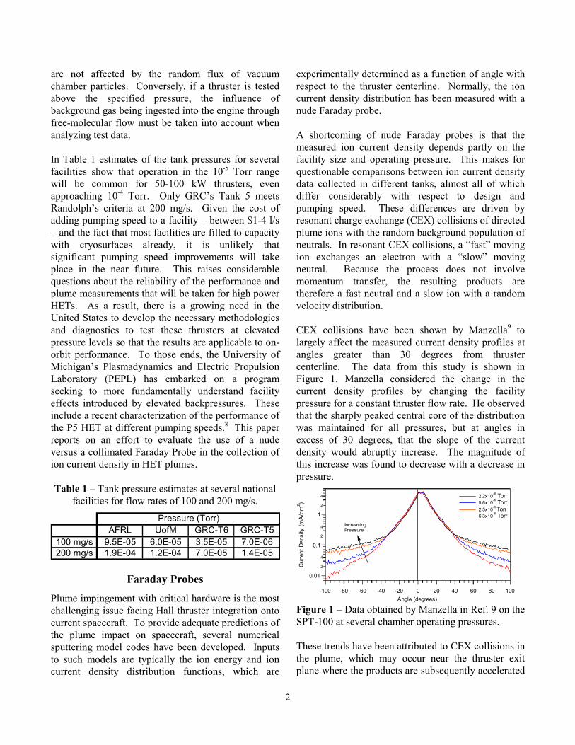
experimentally determined as a function of angle with respect to the thruster centerline. Normally, the ion current density distribution has been measured with a nude Faraday probe. A shortcoming of nude Faraday probes is that the measured ion current density depends partly on the facility size and operating pressure. This makes for questionable comparisons between ion current density data collected in different tanks, almost all of which differ considerably with respect to design and pumping speed. These differences are driven by resonant charge exchange (CEX) collisions of directed plume ions with the random background population of neutrals. In resonant CEX collisions, a “fast” moving ion exchanges an electron with a “slow” moving neutral. Because the process does not involve momentum transfer, the resulting products are therefore a fast neutral and a slow ion with a random velocity distribution. CEX collisions have been shown by Manzella9 to largely affect the measured current density profiles at angles greater than 30 degrees from thruster centerline. The data from this study is shown in Figure 1. Manzella considered the change in the current density profiles by changing the facility pressure for a constant thruster flow rate. He observed that the sharply peaked central core of the distribution was maintained for all pressures, but at angles in excess of 30 degrees, that the slope of the current density would abruptly increase. The magnitude of this increase was found to decrease with a decrease in pressure.
0.01
2
4
0.1
2
4
1
2
4
Cur
rent
Den
sity
(mA
/cm
2 )
-100 -80 -60 -40 -20 0 20 40 60 80 100Angle (degrees)
2.2x10⁻⁶ Torr 5.6x10⁻⁶ Torr 2.5x10⁻⁵ Torr 6.3x10⁻⁵ Torr
Increasing Pressure
Figure 1 – Data obtained by Manzella in Ref. 9 on the SPT-100 at several chamber operating pressures. These trends have been attributed to CEX collisions in the plume, which may occur near the thruster exit plane where the products are subsequently accelerated

3
or at other locations of the plume where the electric field is negligible. Exit plane CEX products are most likely present in the space environment, as these collisions are in regions where the neutral density from the anode is still relatively high. Plume CEX products, however, are believed to be caused primarily by the facility background gases and should therefore be excluded from a current density measurement, which a nude Faraday probe is incapable of doing. The effects of plume CEX products are the most evident in the perimeter, where they lead to an increase in the measured current density. This seems contradictory, as the ion from a CEX collision moves at a much reduced velocity than the original fast ion. So it would seem that an electrode collecting ion current should register a lower current. Haas has recently provided an explanation for this effect.10 Since the collector electrode of a Faraday probe is typically biased 20 V below ground to repel electrons, it may act as a point source potential sink to low-energy CEX ions in the perimeter of the plume where the plasma density is smallest and hence the sheath thickness is greatest. Thus, more CEX ions are collected in the perimeter due to the growing sheath and an artificially large current results. A collimated probe design could possibly mitigate this effect with nude probes, i.e. provide for a method to obtain the true ion current density profile regardless of the facility background pressure. The collimated probe is constructed by adding a long tube to the existing nude Faraday probe design. The collimator is intended to act primarily as a filter for random low energy ions introduced in the plume by charge exchange (CEX) collisions. Exit plane CEX products with a directed velocity are still collected with a collimator. In theory, the collimated current density profile could then be considered the distribution that would exist on-orbit where the population of plume CEX ions is expected to be small. De Grys, et al. recently reported on the theory and design of a collimated Faraday probe.11 Their claim is that the collimator attempts to collect random ions in the plume created by CEX collisions with energies less than 20 eV. This energy threshold was chosen because it is below a typical material energy threshold for sputtering. Ions of these energies are of little interest to plume modeling efforts. In their paper, one of the conclusions from their study was that the
collimator is able to obtain the true ion current density profile regardless of the pumping speed of the facility (i.e. in those facilities at pressures above the Randolph criteria). The purpose of this study is to evaluate this approach for use with HETs in a vacuum facility capable of sustaining pressures below the Randolph criteria for plume characterization. Results obtained with a collimator at these pressures should give the clearest indication of the diagnostics ability to measure the true ion current density. In the following, a review of collimated probe theory is given, then a comparison of the probe design and vacuum facilities used in this study and those in Ref. 11 are presented. Experimental results and discussion of current density measurements obtained at PEPL then follow. Finally, some conclusions on the capabilities of the collimated Faraday probes are offered.
Collimated Faraday Probe Theory
The collimator is a tube with a length to diameter (L/D) ratio greater than unity housing a nude Faraday probe. Figure 2 is a schematic of the collimator geometry. Figure 3 is the idealized geometry of the collimator with respect to the thruster. The thruster is modeled as two point sources (PS1 and PS2), to account for the annular discharge chamber. Figures 4a-b are radial and axial plane views, respectively, which label the relevant geometric quantities. These include Dcup, Lcup, Lcol, and R, which are defined according to Figure 4a. Versions of these figures and the derivation that follows appear in Ref. 11 as well. Some modifications and additions have been made to correct for omissions in that derivation as well as for clarity.

4
Figure 2 – Cross-sectional view of the collimated Faraday probe showing the basic geometry. Venting is through the entrance aperture or space in the rear not occupied by the nude probe and the narrow crossbar shown.
Figure 3 – Idealized geometry of the collimated Faraday probe. The thruster annular discharge chamber is modeled as two point sources (PS1 and PS2).
θ
Figure 4a-b – Radial and axial plane views, respectively, of the collimator geometry. The L/D ratio significantly reduces the view factor for random CEX ions to intersect the collector face. This prohibits only those ions with velocity vectors directed within a small solid angle from entering the collimator aperture and reaching the collector where they are recorded as current. Thus, the collimator acts as a filter for low-energy, random CEX ions. Of

5
course, the collimator also must partially block the ion beam emanating from the thruster. A scale factor is needed to account for the effect of blocking the high-energy ions that are not intended to be filtered. The scale factor is defined as the ratio of beam current that would be collected by an uncollimated probe divided by the current collected by a collimator. Referring to Figure 4b, the scale factor for one point source is then defined as,
=
=
ADBE
F
ADBE
ADCE
AA
AAS φ (1)
Where A denotes an area, and the subscripts either define a noncircular area defined by the labeled points (e.g. ADBE) or a circle defined by the center point (e.g. φF). The task remains to derive expressions for these areas as a function of angle. Because there are two point sources, the scale factors will be referred to as S1 or S2 as defined by the orientation of PS1 and PS2 in Figure 4a. S1 and S2 are not equal for a given angular location, instead, the functions are mirror images of each other about the centerline. Before deriving expressions for the scale factors, consider the current density of a collimated probe. The current density contribution from each point source is related to the beam current density collected by a collimated probe as, ( ) ( ) ( )θθθ 21 JJJcoll += (2) Where Jcoll is the current density of the collimated probe and J1 and J2 refer to the current density contributed by each point source. To get the true beam current density (Jcoll,scaled), the scale factor must be applied to J1 and J2. ( ) ( ) ( ) ( ) ( )θθθθθ 2211, JSJSJ scaledcoll += (3) How much J1 and J2 contribute to Jcoll,scaled is not known, so to use a collimated probe it will be necessary to equate S1 and S2 by another function called Savg,
( ) ( ) ( ) ( ) ( )
( ) ( ) ( )( )θθθθθθθθ
21
2211,
JJSJSJSJ
avg
scaledcoll
+≈+=
(4)
It will be shown later that the maximum difference between S1 and S2 in this study is 2.1%, so the error of equating Savg for S1 and S2 is acceptable. Accordingly, Savg must be the average of S1 and S2,
( ) ( ) ( ) ( ) ( )2
2121
θθθθθ SSSSSavg+≈≈≈ (5)
It is now possible to begin deriving expressions for the scale factors. The derivation will consider PS1 and PS2 simultaneously, making note of the differences as the derivation proceeds. Recalling Eq. 1 above, the derivation begins by obtaining the area of circle F, AφF, which is given by, ( )2AFA F πφ = (6) Where AF refers to the length of the line segment connecting points A and F. A similar convention will be employed for other line segments. To obtain AF, expressions for BI, BC, and AI are needed because, ( ) ( )AIBCBIACAF −+== 22 (7) BI is simply the aperture diameter, which is equal to the collector diameter or twice the radius, cupcup RDBI 2== (8) Using similar right triangles, BC and AI can be calculated from the geometry in Figure 4a.
( )cupRRRLcup
LcolBC −
±
= θθ
cossin
(9)
( )cupRRRLcup
LcolAI +
±
= θθ
cossin
(10)
Where the positive sign in Eqs. 9-10 refers to PS1 and the negative sign to PS2. The expressions for BC and AI are valid for all angles ±90° from centerline, which is the range of angles for which the scale factor has physical meaning. The scale factor is considered valid so long as there is an unobstructed line of sight from the thruster to the collector. The point at which the point sources are obstructed occurs at angles slightly less than 90° in this study. BC actually becomes negative around 81° in this study, reflecting the fact

6
that the scale factor is equal to unity at greater angles. This is because the collector is no longer overlapping the collimator face. Negative values for BC are still valid, this just reflects that point C is to the right of point B (opposite shown in Figure 4b). AI always maintains positive values over the range of angles considered. Substitution of Equations 8-10 yields an expression for AφF,
2
2
sin1
±
−=θ
πφ RLcupLcolRA cupF (11)
Where the positive sign refers to PS1 and the negative to PS2. Obtaining the area AADBE is more involved than AφF. ( )DFGDGEDFEFADBE AAAAA ∆∠∠ +−−= 2φ (12) The areas A∠DFE and A∠DGE are the areas of the circle sectors inside the acute angle defined by the indicated points. The area of triangle ∆DFG is given by, (12) ( )( )FGDHA DFG 5.0=∆ (13) The length FG is given by, ( )AIRAFAGAFFG cup −−=−= (14) The x-y coordinates of point D are critical for finding the length of DH and for determining the length of FH, which will be needed later in the derivation. To determine the coordinates of point D consider the equations defining circle’s F and G, with an origin for both circles at point G. The equation for the circle centered about point G is, 222
cupRyx =+ (15) The equation for the circle centered about point F is, ( ) 222 AFyFGx =++ (16) Solving Eq. 15 for x yields a solution valid for either PS1 (negative root) or PS2 (positive root), 22 yRx cup −±= (17)
Expanding Eq. 16, substituting in for Eq. 17, and then solving for y gives the solution for DH,
( ) 2222
2
2
−−±−±==
FGFGRAF
RDHy cupcup (18)
The first ± on the right hand side of Eq. 18 should be taken as positive, which is applicable to either PS1 or PS2. The second ± should be taken as negative for PS1 and positive for PS2. When BC becomes zero at approximately 81°, so does DH. At angles larger than 81°, Eq. 18 becomes imaginary because it is no longer valid (the circles are not intersecting), thus DH should be set to zero when BC is less than or equal to zero. If the scale factor were valid for all angles, DH would become non-zero once again at about 99 degrees (the angle where AI becomes zero), but this case is not considered. Having solved for y = DH, the x-coordinate (GH) can now be found by substitution of Eq. 18 into Eq. 17,
( )
++−±==
FGRFGAF
xGH cup
2
222
(19)
Where the negative root applies to PS1 and the positive root to PS2. Returning to Eq. 12, it still remains to find the area of the circle sectors DFE and DGE. These areas are given by twice the areas of sectors DFB and DGB∀, DFBAFA DFE ∠=∠
2 (20) DGBRA cupDGE ∠=∠
2 (21) The angles DFB and DGB are given by,
=
=∠ −−
AFDH
DFDHDFC 11 sinsin (22)
∀ Recall that the sector area of a circle is given by,
θ2sec 21 RA tor = .
7
=
=∠ −−
cupRDH
DGDHDGB 11 sinsin (23)
A problem now arises with the arcsine function in Eq. 22 for angles near centerline. Near centerline, the value of FH = GH - FG is negative, that is, point H is between F and G. For these angles, the angles defined in Eqs. 22-23 are obtuse and the arcsine function does not return the correct value. This is why GH was derived above. To correct this situation, the function β is defined and used in place of Eq. 22,
>
≤
−
=−
−
FGGHAFDH
FGGHAFDH
,sin
,sin
1
1πβ (24)
With the equations above, the scale factor can now be written down,
( ) ( )( )FGDHRcupDHRAF
RLcupLcolR
RLcupLcolR
S
cupcup
cup
−
+−
±
−
±
−=
−1222
2
22
sinsin
1
sin1
βθ
π
θπ (25)
Where both positive signs are taken for PS1 and the negative signs for PS2. Note that several other equations are needed to actually compute the scale factors. Figure 5a plots S1, S2, and Savg, using the dimensions for the PEPL setup for a thruster exit plane to collimator entrance aperture distance of 100 cm. Dimension for the probe and thruster are given later in Table 3. Savg attains a maximum value of 1.34 on centerline, and is set to unity at 81º. Note how S1 and S2 are mirror images about the centerline. The dependence of the scale factor with distance is shown in Figure 5b, which also includes the scale factor appropriate for Ref. 11. The scale factor reported in Ref. 11 (not shown) does not agree with the one reported here. In Ref. 11, the scale factor attains a maximum value of nearly 2 on centerline and linearly decays with angle. This appears to be the result of an error in computing the scale factor (the derivation here is nearly identical), and has implications regarding the conclusions of Ref. 11.
The scale factor reported here using the dimensions given in Ref. 11, attains a maximum value of 1.74 on centerline and does not decay as a linear function with angle. The dependence of the scale factor on the ratio of Lcup/R is also shown in Figure 5b. At the equivalent axial locations (exit plane to collimator entrance), the differences between Ref. 11 and this study are a result of using different sized thrusters. The BPT-4000 has a mean diameter of 130 mm, while the thruster in this study, the P5-2, has a mean diameter of 147 mm. The scale factor at 50 cm is also given for reference. Figure 5c plots the difference between the two scale factors, expressed as a percentage of S2. The maximum percentage difference at 100 cm for this study is 2.1%, and at 50 cm it is 12%. Ref. 11 reports the maximum difference as 3% for their setup, while the calculations presented here indicate that this difference is 7.4%. The differences between Ref. 11 and PEPL for the same location are again driven by the thruster size. It does not seem appropriate to use the PEPL probe and thruster at distances approaching 50 cm due to the growing differences between the scale factors and the induced error that would result. At distances approaching 50 cm a more suitable thruster size, without redesigning the probe, would be a device with a mean radius on the order of 50 mm.
Experimental Apparatus
Vacuum Facility All experiments were conducted in the University of Michigan’s Large Vacuum Test Facility (LVTF). The P5-2 was mounted at thruster station 1, as indicated in Figure 6. The LVTF is a stainless steel vacuum chamber that has a diameter of 6 m and a length of 9 m. Two 2,000 CFM blowers and four 400 CFM mechanical pumps evacuate the LVTF to moderate vacuum (30 - 100 mTorr). To reach high vacuum the LVTF is equipped with seven CVI TM-1200 re-entrant cryopumps, each of which is surrounded by a LN2 baffle. The combined pumping speed of the facility is 500,000 l/s on air, and 240,000 l/s on xenon with a base pressure of 2.5x10⁻⁷ Torr. The cryopump system can be operated with any number of pumps in use. For the experiments reported here, the LVTF was

8
operated with seven cryopumps. At the average anode flow rates investigated, 5.30 and 9.95 mg/s, and a 0.76 mg/s cathode flow the operating pressures of the LVTF was approximately 3.4x10⁻⁶ and 5.7x10⁻⁶ Torr on xenon, respectively.
1.35
1.30
1.25
1.20
1.15
1.10
1.05
1.00
Sca
le F
acto
r
-90 -80 -70 -60 -50 -40 -30 -20 -10 0 10 20 30 40 50 60 70 80 90Angle (Degrees)
S1 S2 Savg
2.01.91.81.71.61.51.41.31.21.11.0
Sca
le F
acto
r
-90 -80 -70 -60 -50 -40 -30 -20 -10 0 10 20 30 40 50 60 70 80 90Angle (Degrees)
50 cm 52 cm 52 cm (Ref. 11) 100 cm (PEPL)
121086420
-2-4-6-8
-10
% D
iffer
ence
from
S2
-90 -80 -70 -60 -50 -40 -30 -20 -10 0 10 20 30 40 50 60 70 80 90Angle (Degrees)
50 cm 52 cm 52 cm (Ref. 11) 100 cm (PEPL)
Figures 5a-c – a) The scale factor used for the PEPL probe, b) comparison of the scale factor for several thruster exit plane to entrance aperture distances, and c) the percentage difference in the scale factors for several thruster exit plane to entrance aperture distances. Chamber pressure was monitored using two hot-cathode ionization gauges as indicated in Figure 6. The first gauge was a Varian model 571 gauge with a HPS model 919 Hot Cathode Controller. The second is a Varian model UHV-24 nude gauge with a Varian UHV senTorr Vacuum Gauge Controller. Pressure measurements from both gauges were corrected for
xenon using the known base pressure on air and a correction factor of 2.87 for xenon according to the following equation,12
bbi
c PPP
P +−
=87.2
(26)
Where Pc is the corrected pressure on xenon, Pb is the base pressure, and Pi is the indicated pressure when xenon is flowing into the vacuum chamber.
Figure 6 – Schematic of the LVTF. For comparison, the test results presented in Ref. 11 were taken in a 2.1 m dia. X 7.2 m long stainless steel vacuum chamber, equipped with 4 cryopumps with a combined xenon pumping speed of 60,000 l/sec. Multiple ionization gauges, calibrated on xenon, where used to measure the chamber pressure. The lowest operating pressure reported was 2.3x10⁻⁵ Torr. The base pressure was not reported. Hall Thruster All experiments were performed on the P5-2 Hall thruster. A more detailed discussion of this thruster can be found in Ref. 13. This thruster is designed to operate in both single- and two-stage modes. For these experiments, the electrode used for two-stage operation was replaced with the same ceramic as the chamber walls. This enables the engine to be operated as a single-stage device. The P5-2 has a mean diameter of 147 mm, a channel width of 25 mm, and has nominal power rating of 5 kW. The thruster was allowed to operate for two hours after initial exposure to vacuum to allow for outgassing of the chamber walls. Upon subsequent thruster shutdowns and
9
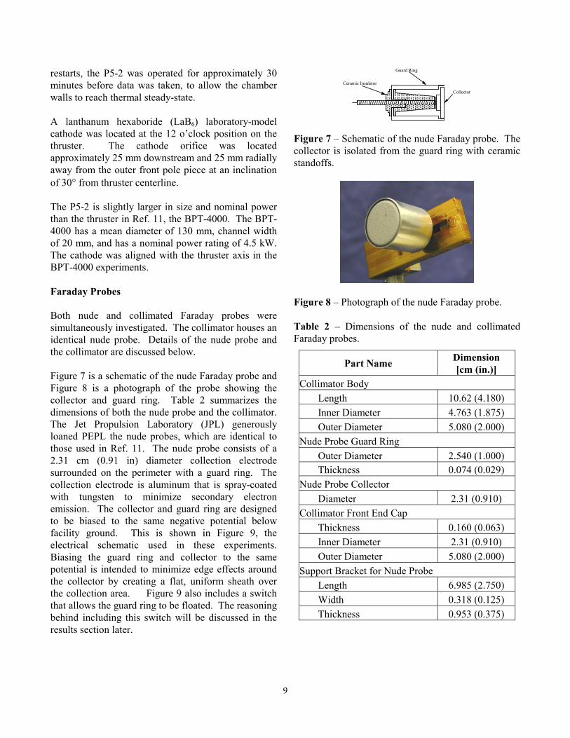
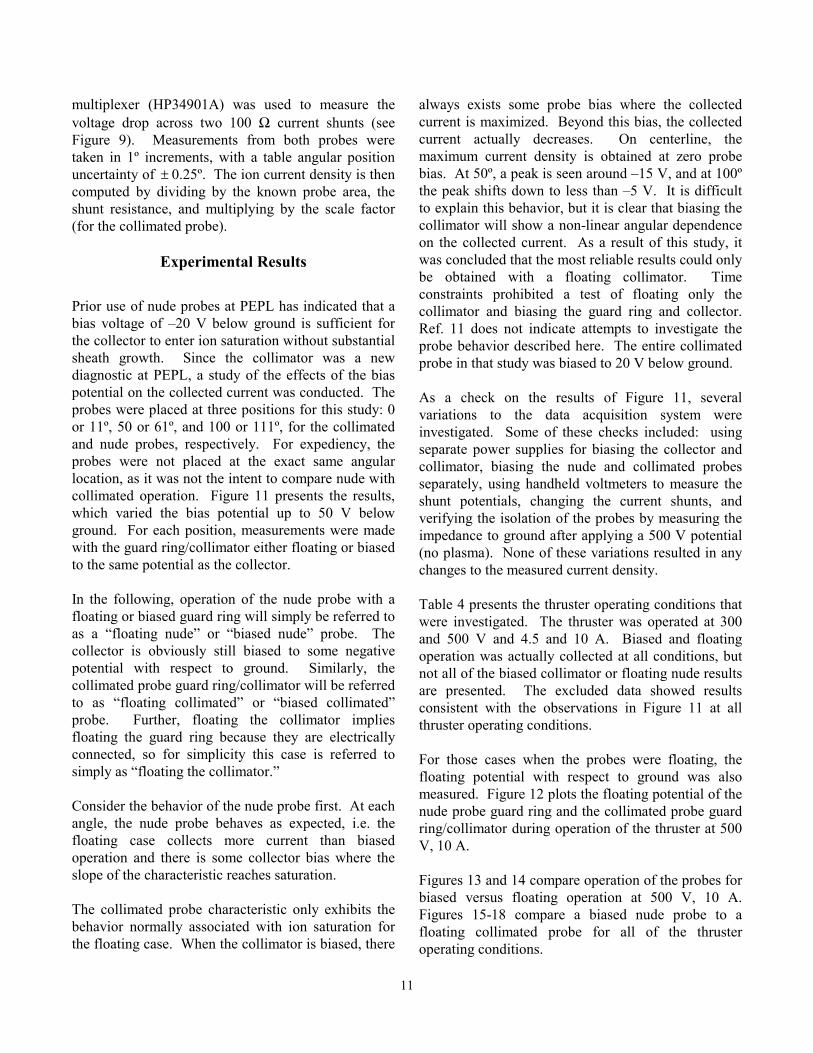
restarts, the P5-2 was operated for approximately 30 minutes before data was taken, to allow the chamber walls to reach thermal steady-state. A lanthanum hexaboride (LaB6) laboratory-model cathode was located at the 12 o’clock position on the thruster. The cathode orifice was located approximately 25 mm downstream and 25 mm radially away from the outer front pole piece at an inclination of 30° from thruster centerline. The P5-2 is slightly larger in size and nominal power than the thruster in Ref. 11, the BPT-4000. The BPT-4000 has a mean diameter of 130 mm, channel width of 20 mm, and has a nominal power rating of 4.5 kW. The cathode was aligned with the thruster axis in the BPT-4000 experiments. Faraday Probes Both nude and collimated Faraday probes were simultaneously investigated. The collimator houses an identical nude probe. Details of the nude probe and the collimator are discussed below. Figure 7 is a schematic of the nude Faraday probe and Figure 8 is a photograph of the probe showing the collector and guard ring. Table 2 summarizes the dimensions of both the nude probe and the collimator. The Jet Propulsion Laboratory (JPL) generously loaned PEPL the nude probes, which are identical to those used in Ref. 11. The nude probe consists of a 2.31 cm (0.91 in) diameter collection electrode surrounded on the perimeter with a guard ring. The collection electrode is aluminum that is spray-coated with tungsten to minimize secondary electron emission. The collector and guard ring are designed to be biased to the same negative potential below facility ground. This is shown in Figure 9, the electrical schematic used in these experiments. Biasing the guard ring and collector to the same potential is intended to minimize edge effects around the collector by creating a flat, uniform sheath over the collection area. Figure 9 also includes a switch that allows the guard ring to be floated. The reasoning behind including this switch will be discussed in the results section later.
Guard Ring Ceramic Insulator
Collector
Figure 7 – Schematic of the nude Faraday probe. The collector is isolated from the guard ring with ceramic standoffs.
Figure 8 – Photograph of the nude Faraday probe. Table 2 – Dimensions of the nude and collimated Faraday probes.
Part Name Dimension [cm (in.)]
Collimator Body Length 10.62 (4.180) Inner Diameter 4.763 (1.875) Outer Diameter 5.080 (2.000) Nude Probe Guard Ring Outer Diameter 2.540 (1.000) Thickness 0.074 (0.029) Nude Probe Collector Diameter 2.31 (0.910) Collimator Front End Cap Thickness 0.160 (0.063) Inner Diameter 2.31 (0.910) Outer Diameter 5.080 (2.000) Support Bracket for Nude Probe Length 6.985 (2.750) Width 0.318 (0.125) Thickness 0.953 (0.375)

10
Figure 9 – Electric schematic of the nude and collimated Faraday probes. The switch allows the guard ring/collimator to float. Figure 10 is photograph of the collimator. The collimator design is identical to the one used in Ref. 11 except for the absence of several vent holes on the main body and a different mounting scheme for the internal nude probe. The mounting scheme would not introduce any significant differences in the measurements. The vent holes were omitted here because they were not deemed necessary due to the high pumping speed of the LVTF. In addition, the vent holes could possibly introduce error by providing additional paths into the collimator interior. The vent to aperture area ratio for the Ref. 11 collimator was 5:1. In comparison, the vent to aperture area ratio for the PEPL collimator is 3.5:1. More discussion on pressure effects will be discussed below. The use of a collimator submersed in a streaming plasma implies certain assumptions about the effects of the collimator on the local plasma. First, it is assumed that the collimator aperture is the axial location where the plume is sampled. The plasma then drifts unimpeded, i.e. free of further CEX collisions or potential gradients, into the collector. If this is not the case then the reliability of the collimator to produce meaningful results is suspect. This assumption also implies that in order to make a comparison with a nude probe, the entrance aperture
of the collimator and the collection surface of the nude probe should be placed in the same axial location.
Figure 10 – Photograph of the collimated Faraday probe. Another assumption is related to the above. In Ref. 11 the collimator body is biased to the same potential as the guard ring and collector of the internal nude probe. Thus, the probe is assumed to be free of potential gradients (excluding thin sheaths) that could affect the plasma. As will be discussed below, biasing the collimator to the collector potential produces unexpected results. Table 3 presents those values necessary to compute the scale factor applicable to this study. The dimensions are based off the thruster size, the probe position, and probe dimensions. Table 3 – Probe and thruster dimensions for computing the scale factor.
Variable Dimension [cm (in.)] R 7.37 (2.90)
Lcup 108.0 (42.51) Lcol 8.00 (3.14) Dcup 2.31 (0.910)
The nude and collimated Faraday probes were positioned 11.50 ± 0.25º apart on an overhead, rotating arm that is attached to a rotary table. The probes were aligned to the center of the P5-2 exit plane and placed 100.0 ± 0.1 cm downstream of the thruster. This allowed the probes to be swept +/-100º from the thruster centerline through the plume. A LabView VI controlled the motion of the rotary table connected to the probe arm. An 11-bit Agilent Data Logger head unit (HP34970A) with a 20-channel
11
multiplexer (HP34901A) was used to measure the voltage drop across two 100 Ω current shunts (see Figure 9). Measurements from both probes were taken in 1º increments, with a table angular position uncertainty of ± 0.25º. The ion current density is then computed by dividing by the known probe area, the shunt resistance, and multiplying by the scale factor (for the collimated probe).
Experimental Results
Prior use of nude probes at PEPL has indicated that a bias voltage of –20 V below ground is sufficient for the collector to enter ion saturation without substantial sheath growth. Since the collimator was a new diagnostic at PEPL, a study of the effects of the bias potential on the collected current was conducted. The probes were placed at three positions for this study: 0 or 11º, 50 or 61º, and 100 or 111º, for the collimated and nude probes, respectively. For expediency, the probes were not placed at the exact same angular location, as it was not the intent to compare nude with collimated operation. Figure 11 presents the results, which varied the bias potential up to 50 V below ground. For each position, measurements were made with the guard ring/collimator either floating or biased to the same potential as the collector. In the following, operation of the nude probe with a floating or biased guard ring will simply be referred to as a “floating nude” or “biased nude” probe. The collector is obviously still biased to some negative potential with respect to ground. Similarly, the collimated probe guard ring/collimator will be referred to as “floating collimated” or “biased collimated” probe. Further, floating the collimator implies floating the guard ring because they are electrically connected, so for simplicity this case is referred to simply as “floating the collimator.” Consider the behavior of the nude probe first. At each angle, the nude probe behaves as expected, i.e. the floating case collects more current than biased operation and there is some collector bias where the slope of the characteristic reaches saturation. The collimated probe characteristic only exhibits the behavior normally associated with ion saturation for the floating case. When the collimator is biased, there
always exists some probe bias where the collected current is maximized. Beyond this bias, the collected current actually decreases. On centerline, the maximum current density is obtained at zero probe bias. At 50º, a peak is seen around –15 V, and at 100º the peak shifts down to less than –5 V. It is difficult to explain this behavior, but it is clear that biasing the collimator will show a non-linear angular dependence on the collected current. As a result of this study, it was concluded that the most reliable results could only be obtained with a floating collimator. Time constraints prohibited a test of floating only the collimator and biasing the guard ring and collector. Ref. 11 does not indicate attempts to investigate the probe behavior described here. The entire collimated probe in that study was biased to 20 V below ground. As a check on the results of Figure 11, several variations to the data acquisition system were investigated. Some of these checks included: using separate power supplies for biasing the collector and collimator, biasing the nude and collimated probes separately, using handheld voltmeters to measure the shunt potentials, changing the current shunts, and verifying the isolation of the probes by measuring the impedance to ground after applying a 500 V potential (no plasma). None of these variations resulted in any changes to the measured current density. Table 4 presents the thruster operating conditions that were investigated. The thruster was operated at 300 and 500 V and 4.5 and 10 A. Biased and floating operation was actually collected at all conditions, but not all of the biased collimator or floating nude results are presented. The excluded data showed results consistent with the observations in Figure 11 at all thruster operating conditions. For those cases when the probes were floating, the floating potential with respect to ground was also measured. Figure 12 plots the floating potential of the nude probe guard ring and the collimated probe guard ring/collimator during operation of the thruster at 500 V, 10 A. Figures 13 and 14 compare operation of the probes for biased versus floating operation at 500 V, 10 A. Figures 15-18 compare a biased nude probe to a floating collimated probe for all of the thruster operating conditions.

12
18
19
20
21
22
23
24
25
26
27
28
29
30
-32 -30 -28 -26 -24 -22 -20 -18 -16 -14 -12 -10 -8 -6 -4 -2 0
Vbias (Volts)
V pro
be s
hunt
(mV)
Nude,Floating,-11 Deg
Nude,Biased,-11 Deg
Collimated,Floating,0 Deg
Collimated,Biased,0 Deg
0
0.1
0.2
0.3
0.4
0.5
0.6
0.7
0.8
0.9
1
1.1
1.2
-55 -50 -45 -40 -35 -30 -25 -20 -15 -10 -5 0
Vbias (Volts)
V pro
be s
hunt
(mV)
Nude, Floating, -61 DegNude, Biased, -61 DegCollimated, Floating, -50 DegCollimated, Biased, -50 Deg
0
0.025
0.05
0.075
0.1
0.125
0.15
0.175
0.2
0.225
0.25
-55 -50 -45 -40 -35 -30 -25 -20 -15 -10 -5 0
Vbias (Volts)
V pro
be s
hunt
(mV)
Nude, Floating, -111 DegNude, Biased, -111 DegCollimated, Floating, -100 DegCollimated, Biased, -100 Deg
Figure 11 – Effect of varying the probe bias at several angular positions. Cases when the guard ring/collimator are biased and floating are shown. (300 V, 4.5 A thruster operation)
Table 4 – P5-2 operating conditions.
Vd (V) Id (A)
Anode Flow
(mg/s)
Cathode Flow
(mg/s) Iim (A) Iom (A) Vc-g (V)Pressure (Torr-Xe)
Bias (V)
Biased or Floating Guard Ring?
300 4.44 5.25 0.76 1.74 1.24 -25.7 3.4E-06 -20 Floating300 4.46 5.25 0.76 1.74 1.24 -25.8 3.4E-06 -20 Biased500 4.56 5.33 0.76 2.50 2.00 -21.7 3.4E-06 -20 Floating500 4.56 5.33 0.76 2.50 2.00 -21.3 3.4E-06 -20 Biased
300 9.87 10.01 0.76 3.49 2.51 -23.8 5.7E-06 -20 Floating300 9.87 10.01 0.76 3.49 2.51 -23.2 5.7E-06 -20 Biased500 10.13 9.91 0.76 4.51 3.80 -22.4 5.7E-06 -20 Floating 500 10.04 9.91 0.76 4.51 3.80 -22.8 5.7E-06 -20 Biased
-3
-2
-1
0
1
2
3
Floa
ting
Pote
ntia
l (V)
-90 -80 -70 -60 -50 -40 -30 -20 -10 0 10 20 30 40 50 60 70 80 90Angular Position (Degrees)
500V, 10A Nude Collimated
Figure 12 – Floating potential of the nude probe guard ring and collimated probe guard ring/collimator. (500 V, 10 A thruster operation)
0.01
2
4
68
0.1
2
4
68
1
2
Cur
rent
Den
sity
( mA/
cm2 )
-90-80-70-60-50-40-30-20-10 0 10 20 30 40 50 60 70 80 90Angular Position ( Degrees )
Nude: 500V, 10A Bias Floating
Figure 13 – Ion current density versus position for a nude probe under biased or floating operation of the guard ring. (500 V, 10 A thruster operation)
13
0.001
0.01
0.1
1
Cur
rent
Den
sity
( mA/
cm2 )
-90-80-70-60-50-40-30-20-10 0 10 20 30 40 50 60 70 80 90Angular Position ( Degrees )
Collimated 500V, 10A
Bias Floating
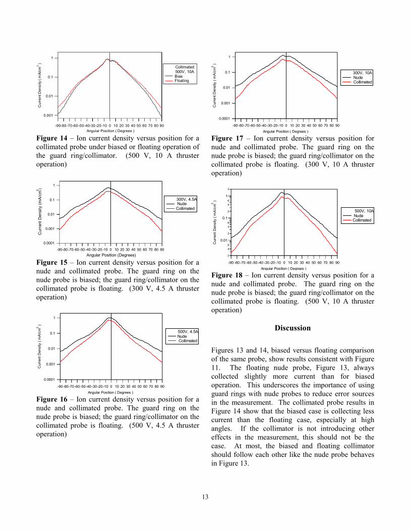
Figure 14 – Ion current density versus position for a collimated probe under biased or floating operation of the guard ring/collimator. (500 V, 10 A thruster operation)
0.0001
0.001
0.01
0.1
1
Cur
rent
Den
sity
(mA/
cm2 )
-90-80-70-60-50 -40-30-20-10 0 10 20 30 40 50 60 70 80 90 Angular Position (Degrees)
300V, 4.5A NudeCollimated
Figure 15 – Ion current density versus position for a nude and collimated probe. The guard ring on the nude probe is biased; the guard ring/collimator on the collimated probe is floating. (300 V, 4.5 A thruster operation)
0.0001
0.001
0.01
0.1
1
Cur
rent
Den
sity
( m
A/cm
2 )
-90-80-70-60-50-40-30-20-10 0 10 20 30 40 50 60 70 80 90Angular Position ( Degrees )
500V, 4.5ANude Collimated
Figure 16 – Ion current density versus position for a nude and collimated probe. The guard ring on the nude probe is biased; the guard ring/collimator on the collimated probe is floating. (500 V, 4.5 A thruster operation)
0.0001
0.001
0.01
0.1
1
Cur
rent
Den
sity
( m
A/cm
2 )
-90-80-70-60-50-40-30-20-10 0 10 20 30 40 50 60 70 80 90Angular Position ( Degrees )
300V, 10A Nude Collimated
Figure 17 – Ion current density versus position for nude and collimated probe. The guard ring on the nude probe is biased; the guard ring/collimator on the collimated probe is floating. (300 V, 10 A thruster operation)
2
46
0.01
2
46
0.1
2
46
1
2
Cur
rent
Den
sity
( m
A/cm
2 )
-90 -80 -70 -60 -50 -40 -30-20 -10 0 10 20 30 40 50 60 70 80 90Angular Position ( Degrees )
500V, 10A NudeCollimated
Figure 18 – Ion current density versus position for a nude and collimated probe. The guard ring on the nude probe is biased; the guard ring/collimator on the collimated probe is floating. (500 V, 10 A thruster operation)
Discussion
Figures 13 and 14, biased versus floating comparison of the same probe, show results consistent with Figure 11. The floating nude probe, Figure 13, always collected slightly more current than for biased operation. This underscores the importance of using guard rings with nude probes to reduce error sources in the measurement. The collimated probe results in Figure 14 show that the biased case is collecting less current than the floating case, especially at high angles. If the collimator is not introducing other effects in the measurement, this should not be the case. At most, the biased and floating collimator should follow each other like the nude probe behaves in Figure 13.

14
Referring back to Figure 1, Manzella observed that the central core of the ion current density profile was largely unaffected roughly within ±30º from centerline. Changing the facility pressure like Manzella did is analogous to the intended purpose of the collimated Faraday probe, but instead of filtering CEX products, Manzella created them. While the trends of Figure 1 may not be reproduced exactly with a collimated probe versus a nude probe, it does not seem unreasonable to expect that the two approaches (i.e. changing the pressure or using a collimator) should roughly mimic each other. Unfortunately, this is not the case in Figures 15-18, which do not exhibit the unaffected central core shown in Figure 1. The figures consistently reveal that the floating collimator collects less current at all angles than the biased nude probe. If the biased collimator had been used, the differences would be greater. Table 5 shows the ratio of the collimated current density to the nude current density. There is a 33-48% drop between the measured current densities of the two probes (even after applying the scale factor). Some of the differences should be attributed to the collimator acting as a low energy filter for CEX ions, but it is not immediately evident how to quantify how much of the difference between the probes is a result of that filtering and not to some other process internal to the collimator. The differences could be attributed to pressure effects, potential gradients in the probe, or the scale factor itself. Some first order estimates of these possibilities will be discussed below. Table 5 – Ratio of the ion current density for the floating collimated and biased nude probes on thruster centerline.
Condition jcoll/jnude 300V, 4.5A 0.58 300V, 10A 0.52 500V, 4.5A 0.67 500V, 10A 0.62
An estimate of the beam attenuation through CEX collisions is possible by considering the ion continuity equation in one dimension. After integration over some path length, z, the ratio of the initial to the final ion current density can be estimated with,7
( )znjj
cebz σ−= exp (27)
Where jz is the ion current density at z, j is the initial ion current density, nb is the background gas density, and σce is the CEX cross-section. Equation 27 is used to calculate the beam attenuation ratio over a 100 cm path length, assuming a neutral temperature of 300 K, and a charge-exchange cross-section of 55 Å2.14 The cross-section from Ref. 14 is only strictly valid for 300 eV ions, but it will be used here for 500 eV ions as an order of magnitude value of the true cross-section. In the calculations, recombination with electrons and higher order CEX collisions are neglected, as the mean free path’s for these types of collisions is greater than a 100 cm. Table 6 shows that the beam attenuation is 6-10% at the operating pressures in these experiments, which is not enough to account for the observed differences between the nude and collimated probes. Other processes internal to the probe must be at work to account for the observed attenuation. Table 6 – Beam current density attenuation as a result of CEX collisions over a 100 cm path length at different background pressures.
Pressure (Torr) Attenuation 3.4 x 10⁻⁶ 0.94 5.7 x 10⁻⁶ 0.90
Another possibility is that beam attenuation is caused not by the ion transit from the thruster to the probe, but by CEX collisions inside the collimator. The ions only travel 8 cm within the collimator, so the pressure would have to be extremely high to account for this situation. Table 7 shows the internal collimator pressure required to account for the beam attenuation in Table 5 after adding back the attenuation for CEX collisions over the first 100 cm shown in Table 6. The calculations indicate pressures of 2-3 x 10⁻⁴ Torr would be required to account for the observed differences in the probes. Such a high pressure is not likely considering the pumping speed of the LVTF and the 3.5:1 venting ratio of the collimator. A justification for why this is so unlikely is given in the following calculation.

15
Table 7 – Internal collimator pressure required to account for the observed beam attenuation.
Condition Pressure (Torr) 300V, 4.5A 3 x 10⁻⁴ 300V, 10A 3 x 10⁻⁴ 500V, 4.5A 2 x 10⁻⁴ 500V, 10A 2 x 10⁻⁴
Consider mass conservation for a control volume surrounding the collimator. The particle flux entering the collimator is dominated by ions because of their large directed velocities. To illustrate why this is true, typical values for Hall thruster plasmas and the background pressure were used to calculate the ratio of ion flux to neutral flux. The results showed that the ratio of ion to neutral flux was between 200-450 over the pressures and ion energies of interest. Further, assume that all ions entering the collimator are neutralized upon collision with the walls or the collector. Under these assumptions, steady-state mass conservation requires that,
( )outinnout
XeiniiXe AAvnmAvnm +=4
(28)
Where Ain and Aout refer to the entrance aperture area and the space in the rear of the collimator not occupied by the nude probe, respectively. The rest of the symbols have their usual meaning. The ion velocity is obtained by assuming electrostatic acceleration at the discharge voltage of interest. Ion density is found from the current collected by the nude probe interior to the collimator. Neutrals are assumed to be thermalized at 300 K and the exit areas are known. Under these assumptions, the internal number density of neutrals can be calculated from Equation 28 above and then expressed in terms of a neutral pressure. Table 8 presents the results of these calculations, which show that under these simplifying assumptions the internal pressure of the probe ranges from 4-8 x 10⁻⁶ Torr. These pressures are on the order of the background pressure in the facility during the experiments and are at least a factor of 25 lower than the pressures required if the attenuation was due to CEX collisions interior to the probe. The previous calculations effectively rule out attenuation by high neutral pressures interior to the
collimator. Two remaining possibilities are the scale factor and potential gradients interior to the probe. Error with the scale factor has already been shown to be on the order of 2% for these experiments. However, the scale factor is computed under the assumption that the Hall thruster is adequately modeled as a set of point sources. The three-dimensional nature of the thruster may be influencing the measured current somehow, but will not be considered here. There is also the possibility that the sheath around the collimator aperture is reducing the entrance area. This is unlikely because the sheath thickness likely to be encountered in the plume at 1 m results in a negligible decrease of the effective aperture area. For example, if the density is on the order of 1017 m-3 and the electron temperature is 2 eV, the Debye length is 0.03 mm. If the sheath is conservatively estimated as five times the Debye length, this reduces the aperture area only by 2%. Table 8 – Pressure inside the collimator from mass conservation.
Condition Collimator Internal Pressure (Torr)
300 V, 4.5 A 4 x 10⁻⁶ 300V, 10A 6 x 10⁻⁶ 500 V, 4.5 A 7 x 10⁻⁶ 500V, 10A 8 x 10⁻⁶
The remaining possibility involves adverse potential gradients interior to the probe. The electric fields would be either radial electric fields that steer ions away from the collector, or axial fields that decelerate the ions so that the collected current decreases. Axial fields are extremely unlikely due to the geometry of the collimator and radial electric fields would have to persist on the order of 2-4 x 10³ V/m to steer an ion from centerline to the edge of the collector. This field strength equates to a potential drop of approximately 50-80 V, which is also very unlikely to exist inside the collimator. Further consideration of possible sheath effects around the collector and the sidewalls is beyond the scope of this paper.
Conclusions and Future Work
The trends observed in this investigation have led to substantially more questions than they have answered. Order of magnitude estimates have shown that the

16
pressure inside the collimator is unlikely to account for the differences between the nude and collimated probes. Electric fields persisting throughout the collimator interior have also been ruled out. The possibility of sheath effects still affecting the measurement has not been evaluated. Clearly, further study is required to bring the collimated Faraday probe to a maturity level sufficient for use in evaluating Hall thruster plumes. One combination that was not tested here is floating the collimator while biasing the guard ring and collector. This combination may mitigate the effects of the collimator on the plasma while still ensuring a flat sheath over the collector. Other investigations may interrogate the probe interior itself by measuring the internal pressure and plasma properties with ionization gauges and electrostatic probes. Numerical modeling of the probe is also being considered, as are alternative designs to the probe geometry and materials.
Acknowledgements
We would like to dedicate this paper to the victims and their families of the terrorist attacks on the United States of America on September 11, 2001. Completing this manuscript during the week of the attacks was difficult, as it suddenly did not seem to be as important as it once did. Our hearts and prayers go out to all those who have been forever changed by this senseless tragedy. Additionally, we would like to thank: Dr. Colleen Marrese at JPL for loaning PEPL the nude Faraday probes, undergraduates S. Brittain, O. Gandara, J. Kennedy, and B. Lerg for designing the probe arm and collimator, T. Larrow for fabricating the hardware used in this study, and the departmental technical staff and other graduate students at PEPL for help in maintaining the facilities. This research was supported by the Air Force Office of Scientific Research grants F49620-00-1-0201 and F49620-01-1-0061 (Dr. Mitat Birkan is the contract monitor for both). The authors are greatly appreciative of this support.
References
1. Sankovic, J. M., Hamley, J. A., Haag, T. W.,
“Performance Evaluation of the Russian SPT-100 Thruster at NASA LeRC,” IEPC-93-094, 23rd International Electric Propulsion Conference, Seattle, WA, Sept 13-16, 1993.
2. Garner, C. E., Brophy, J. R., Polk, J. E., Pless, L. C., “A
5,730-Hr Cyclic Endurance Test of the SPT-100,” AIAA-95-2667, 31st Joint Propulsion Conference, San Diego, CA, July 10-12, 1995.
3. Hargus, W. Jr., Fife, J. M., Mason, L., Jankovsky, R.,
Haag, T., Pinero, L., Snyder, J. S., “Preliminary Performance Results for the High Performance Hall System SPT-140,” AIAA-2000-3250, 36th Joint Propulsion Conference, Huntsville, Alabama, July 17-19, 2000.
4. Fife, J. M., Hargus, W. Jr, Jaworske, D. A., Sarmient,
C., Mason, L., Jankovsky, R., Snyder, J. S., Malone, S., Haas, J., Gallimore, A., “Spacecraft Interaction Test Results of the High Performance Hall System SPT-140,” AIAA-2000-3521, 36th Joint Propulsion Conference, Huntsville, AL, July 17-19, 2000.
5. Mason, L.S., Jankovsky, R.S., Manzella, D.H., “1000
Hours of Testing on a 10 Kilowatt Hall Effect Thruster,” AIAA-2001-3773, 37th Joint Propulsion Conference, Salt Lake City, UT, July 8-11, 2001.
6. Jankovsky, R. S., Jacobson, D. T., Mason, L. S.,
Rawlin, V. K., Mantenieks, M. A., Manzella, D. H., Hofer, R. R., Peterson, P. Y., “NASA’s Hall Thruster Program,” AIAA-2001-3888, 37th Joint Propulsion Conference, Salt Lake City, UT, July 8-11, 2001.
7. Randolph, T., Kim, V., Kaufman, H., Kozubsky, K.,
Zhurin, V., Day, M. “Facility Effects on Stationary Plasma Thruster Testing,” IEPC-93-93, 23rd International Electric Propulsion Conference, Seattle, WA, Sept 13-16, 1993.
8. Hofer, R. R., Peterson, P. Y., Gallimore, A. D.,
“Characterizing Vacuum Facility Backpressure Effects on the Performance of a Hall Thruster,” IEPC-01-045, 27th International Electric Propulsion Conference, Pasadena, CA, Oct 14-19, 2001.
9. Manzella, D. H., Sankovic, J. M., “Hall Thruster Ion
Beam Characterization,” AIAA-95-2927, 31st Joint Propulsion Conference, San Diego, CA, July 10-12, 1995.

17
10. Haas, J. M., “Low-Perturbation Interrogation of the
Internal and Near-field Plasma Structure of a Hall Thruster using a High-Speed Probe Positioning System,” Ph.D. thesis, Dept. of Aerospace Engineering, University of Michigan, pp. 176-186, Feb., 2001.
11. de Grys, K. H., Tilley, D. L., Aadland, R. S., “BPT Hall
Thruster Plume Characteristics,” AIAA-99-2283, 35th Joint Propulsion Conference, Los Angeles, CA, June 20-24, 1999.
12. Dushman, S., Scientific Foundations of Vacuum
Technique, Vol. 4, Wiley, New York, 1958. 13. Hofer, R. R., Peterson, P. Y., Gallimore, A. D., “A High
Specific Impulse Two-Stage Hall Thruster with Plasma Lens Focusing,” IEPC-01-036, 27th International Electric Propulsion Conference, Pasadena, CA, Oct 14-19, 2001.
14. Pullins, S., Dressler, R. A., Chiu, Y. –H., Levandier,
D.J., “Ion Dynamics in Hall Effect and Ion Thrusters: Xe+ + Xe Symmetric Charge Transfer,” AIAA-2000-16470, 38th Aerospace Sciences Meeting & Exhibit, Reno, NV, Jan 10-13, 2000.