Embed Size (px)
Citation preview
A
NISTIR 6736
core product model for representingdesign information
Steven J. Fenves
NISTIR 6736
A CORE PRODUCT MODEL FOR REPRESENTING DESIGN INFORMATION Steven J. Fenves1
February 2001
A core product model for representingdesign information
Steven J. FenvesGuest Researcher, MSID
MEL
October 2002
U.S. DEPARTMENT OF COMMERCEDonald L. Evans, Secretary
TECHNOLOGY ADMINISTRATIONPhillip J. Bond, Under Secretary of Commerce for Technology
NATIONAL INSTITUTE OF STANDARDS AND TECHNOLOGYArden L. Bement, Jr., Director
Contents Abstract ……………………………………………………………………………… 5 1. Motivation ……………………………………………………………………….. 6 2. Organizational Setting …………………………………………………………... 6
2.1 The Knowledge-based System Interoperability Project ………………...6 2.2 Related Projects …………………………………………………………7
3. Related Research …………………………………………………………………7 3.1 Product Modeling ……………………………………………………….7 3.2 Design Information Flow Modeling …………………………………… 9
4. Objectives ……………………………………………………………………… 10 5. Pragmatic Study ………………………………………………………………... 10 6. The Core Representation ……………………………………………………….. 11
6.1 Representation of Attributes and Class Types ………………………… 11 6.2 Semantics ……………………………………………………………… 12 6.3 Class Hierarchy ………………………………………………………... 16 6.4 Associations and Aggregations ………………………………………... 17 6.5 Relationships …………………………………………………………... 18
7. Present and Potential Applications ……………………………………………… 19 7.1 Design Repository ……………………………………………………... 19 7.2 Open Assembly Design Environment 7.3 Design for Tolerancing ………………………………………………… 21 7.4 Design-Process Planning Integration …………………………………... 21
8. Areas for Future Research ………………………………………………………. 22 8.1 Extensions to Support of Interoperable Tools …………………………. 24 8.2 Exploration of Applicability to Full Lifecycle of Artifact …………….. 24
9. Summary ………………………………………………………………………... 25 Acknowledgements …………………………………………………………………. 25 References …………………………………………………………………………... 26 Appendix A: Comparison of Four Product Models ………………………………… 33 Appendix B: The Core Model ………………………………………………………. 36
- 2 -
LIST OF FIGURES 1. Classes ……………………………………………………………………………. 13 2. Class Hierarchy …………………………………………………………………… 16 3. Associations and Aggregations …………………………………………………… 17 4. Relationships ……………………………………………………………………… 18 5. Complete Class Diagram …………………………………………………………. 19 6. Partial Artifact Class Hierarchy …………………………………………………… 23 B1. Class Diagram Implemented ……………………………………………………… 34
- 3 -
LIST OF TABLES 1. Mapping of Information Flow Model States to Core Model Object Classes ……. 20 2. Possible Extensions to Core Model ……………………………………………… 20 3. Partial Taxonomy of Artifacts …………………………………………………… 22
- 4 -
A CORE PRODUCT MODEL FOR REPRESENTING DESIGN INFORMATION Steven J. Fenves Abstract The report presents a core model for representing design information, motivated by the perceived needs of next-generation product development systems and drawing content-level requirements from a related study of design information flows. The core model was synthesized from a comparison of several independently-developed design artifact representations. The primary objective of the report is to provide a base-level product model that is: not tied to any vendor software; open; non-proprietary; simple; generic; expandable; independent of any one product development process; and capable of capturing the engineering context that is most commonly shared in product development activities. The core model focuses on artifact representation including function, form, behavior and material, physical and functional decompositions, and relationships among these concepts. The model is heavily influenced by the Entity-Relationship data model; accordingly, it consists of two sets of classes, called object and relationship, equivalent to the UML class and association class, respectively. It is expected that the core model may eventually serve as a precursor for STEP in the lifecycle of a product, capturing all information relevant to the ongoing design process until the product design is firmed up, approved and committed to purchasing or manufacturing. Aspects of extensions of the model in these directions are discussed. Keywords: product modeling, information modeling, data modeling, artifact, form, function, behavior, Entity-Relationship data model, next-generation product development tools
- 5 -
1. MOTIVATION Product development is increasingly performed by geographically and temporally distributed teams with a high level of outsourcing of many phases of the product development process. As the complexity of products increases further and product development becomes even more distributed, new tools will be needed to address a broader spectrum of product development activities than do traditional Computer Aided Design and Engineering (CAD/CAE) systems. Next-generation tools will require representations that allow all information used or generated in the various product development activities to be transmitted to other activities by way of direct electronic interchange. Furthermore, product development across companies, and even within a single company, will almost invariably take place within a heterogeneous software environment. As a result, there is a greater need for the support of the formal representation, capture, and exchange of the entire range of information generated and used in the product development process, not just of the representation of the product resulting from the completion of the design process. The ability to effectively and formally capture additional types of information will become a critical issue. This report provides a core representation for product development information which can form the basis of future systems that respond to the demands sketched above. This report seeks to address potential interoperability problems proactively, rather than reactively, by providing this representation core as a foundation for improved interoperability among software tools in the future (Shooter et al., 2000b). This work focuses on an artifact representation that encompasses a broad range of engineering design concepts beyond the artifact’s geometry, including function, form, behavior and material, as well as physical and functional decompositions, mappings between function and form, and various kinds of relationships among these concepts. The development of a generic infrastructure for the next generation of product development tools is an effort that neither industry nor the computer aided design, manufacturing and engineering (CAD/CAM/CAE) tool vendor community is likely to undertake alone. The National Institute of Standards and Technology (NIST), which has U.S. industry as its primary customer and works to address problems that have significance to industry, is well situated to invest in an effort to anticipate and address interoperability needs in next-generation product development tools. This report is one component of that effort. 2. ORGANIZATIONAL SETTING
2.1. The Knowledge-based System Interoperability Project The work reported herein is a component of the Knowledge-based System Interoperability Project within the Product Engineering Program (PEP) of the Manufacturing Systems Integration Division (MSID) within the Manufacturing Engineering Laboratory (MEL) of NIST. The goal of this project is to identify the knowledge representation needs for next-generation product development systems, and to
- 6 -
develop a generic core representation for product development knowledge on which future systems can be built. This project seeks formal representations that are not tied to any one specific product development process or single vendor software solution, are open, non-proprietary, simple and generic, and are capable of capturing knowledge commonly used in product development activities. The project deals with both high-level modeling of the flow of information through the product development process and information modeling of product development knowledge. The foundation of information modeling of product development knowledge is that of modeling the product representation itself, the subject of this report.
2.2. Related Projects The Design for Tolerancing of Electro-mechanical Assemblies (DFT) project within PEP is developing concepts, methods and technologies to advance tolerancing decisions to the earliest possible stages of design and defining a multi-level approach called Design For Tolerancing that enables tolerancing to be addressed through the entire design life (Roy et al., 1999: Sudarsan et al., 2000). As part of DFT, the project is developing an integrated, comprehensive, and neutral object architecture for function-assembly-behavior modeling. The NIST Design Repository project, also within PEP, has as its goal the development of an information modeling framework to support the creation of design repositories, the next generation of design databases, and implementation of a prototype design repository tool suite (Szykman et al., 2000). The information modeling framework is based on a versatile, but abstract, product model. The Design/Process Planning Integration (DPPI) project within the Predictive Process Engineering Program has the goal of demonstrating interoperability and enhanced performance between design and process planning by providing process information to the designer, thus allowing him/her to make more informed design decisions, particularly at the early conceptual stages of design (Feng et al, 1999; Feng et al., 2000a: Feng et al., 2000b). The project is developing a product model to which process information is linked. An earlier project, the Object-Oriented Distributed Design Environment Project, developed a software prototype for the Knowledge-based System Interoperability Project, using its own product model. 3. RELATED RESEARCH
3.1. Product Modeling Traditional CAD systems are largely limited to the representation of geometric data. New classes of tools that support function- and knowledge-based design, product data management and concurrent engineering have been focusing primarily on database-related issues and do not place a primary emphasis on information models for artifact
- 7 -
representation, with representation of the design artifact itself still generally limited to geometry, thus limits the utility of these tools in engineering (see, e.g., Bliznakov et al., 1996; Hardwick and Loffredo, 1995; Kim et al., 1996; Shah et al., 1996; Wood and Agogino, 1996). The product model presented here follows the tradition of work in the area of artifact representation. The division of artifact information into the categories of form, function, and behavior has its roots in earlier work in intelligent design systems. Examples of such work from artificial intelligence include qualitative simulation (de Kleer and Brown, 1983), behavioral and functional representation (Iwasaki and Chandrasekaran, 1992), functional representation (Chandrasekaran et al., 1993) and successive representations from projects such as KRITIK (Goel, Bhatta et al., 1996) and INTERACTIVE KRITIK (Goel, Gomez et al., 1996), the YMIR project (Alberts and Dikker, 1992), and others. Work in engineering design includes CONGEN (Gorti et al., 1998), the MOSES project (Henson et al., 1994), the GNOSIS Intelligent Manufacturing System project (Ranta et al., 1996), the Function-Behavior-State Modeler (Umeda et al., 1996), and the function-behavior-structure framework (Qian and Gero, 1996). The work presented here is most directly descended from the representation developed as part of the NIST Design Repository project (Szykman et al., 1999; Szykman et al., 2000). That work is based in part on the CONGEN architecture (Gorti et al., 1998), which made use of the SHARED object model (Wong and Sriram, 1993) as a basis. The model presented here shares both conceptual and representational aspects with that developed by the MOKA (Methodology and tools Oriented to Knowledge based engineering Applications) Consortium, an ESPRIT-funded collaborative project of the European Union (Stokes, 2001). The reader may rightly question the need for another product model, given NIST’s and MEL’s leadership in the development of STEP (Standard for the Exchange of Product model data) and their continued commitment to its maintenance and enhancement (ISO,1994; PDES, 1999; Kemmerer, 1999). STEP is a mature and widely used standard for the exchange of product data after that product has been designed. In practice, STEP tends to be invoked only late in the product development process, after all design decisions have been made and when the product is ready to be purchased, manufactured or assembled. Thus, STEP is used for the exchange of information that is the outcome of design activities, rather than for the information produced and used through the development of the design. STEP provides no support for design evolution, for the early phases of design when descriptive information is sparse, and for the ready attachment of various forms of knowledge rather than pure data. The work presented here may be seen as intended to serve as the precursor for STEP in the lifecycle of a product, capturing all the information relevant to the ongoing design process until the product design is firmed up, approved and committed to purchasing or manufacturing. A production version of the core product model presented here could be readily fitted with a translator that would extract the information representing the finished design and convert it to the STEP format for transmission to subsequent manufacturing activities.
- 8 -
3.2. Design Information Flow Modeling
The Open Assembly Design Environment (OpenADE), another component of the Knowledge-based System Interoperability Project within PEP, is addressing design information interchange and agent interoperability issues within the context of a collaborative design framework (Lyons et al., 1999; Angster et al., 1998, Shooter et al., 2000a). OpenADE seeks to formalize the semantics, types and levels of design information. One step in this direction is the modeling of the flow of design information. The model for the flow of design information differs from a design process model because it models information flows among design activities irrespective of the particular sequence in which the activities are executed. The model classifies design information into various types and organizes these types into information states and levels of abstraction. The information flow model assumes that design activities operate in two modes. The iterative mode accounts for the various feedback loops that occur as designers seek to satisfy design goals. The layered mode corresponds to the levels of abstraction designers use as they represent the current state of the design at different levels of completeness and fidelity. The design information flow model identifies the following states of information. The Customer Needs state describes what customers need or desire in a product. The Specifications state describes customers’ needs in terms of evaluation criteria. The Engineering Requirements state formalizes the requirements that the artifact must satisfy. The Family of Solutions state includes one or more partial or prototypical descriptions of the artifact proposed as the design solution. The Proposed Artifact state provides an extensional description of the artifact at a given level of abstraction. The Observed Behavior state includes the artifact’s behavior as derived, i. e., simulated, from its description. The Evaluated Behavior state describes the extent to which the proposed artifact’s observed behavior matches its intended behavior. Finally, the Evaluated Requirements state includes an evaluation of the proposed artifact’s degree of satisfaction of the engineering requirements. As stated above, these states are iterated on within one level of abstraction, as well as expanded progressively as the design is carried out to increasing detail, i. e., increasingly lower levels of abstraction. Possible extensions of the core model to more fully support the information flow model are discussed in Section 7.2. 4. OBJECTIVES The primary objective of the work presented in this report is to provide a base-level foundation core product model to underlie the information flow model over all levels of abstractions and one that retains the principles of the OpenADE project, namely, a representation that is:
• not tied to a single vendor software solution, • open and non-proprietary, • simple and generic,
- 9 -
• expandable, • not dependent on any one product development process, and • capable of capturing that portion of the engineering context that is most
commonly shared in product development activities. This work is, in itself, not a development of a new standard. Rather, it is an attempt to identify needs and provide a generic information representation core that can serve as a foundation for development of new systems, which at some future point may be the subject of standards development efforts. The work reported here can provide a starting point for future standards. Simplicity is therefore a key requirement for the representation. Simplicity also makes a proposed representation more appealing to users. The product information representation also needs to be domain-independent and not be tied to any one product development process. It is expected that the core model presented in this report, with suitable modifications based on experience in usage, can serve as the information transfer mechanism for next-generation product development tools, either in the basic form presented here or as the base-level representation of the multilevel design information flow model presented in (Shooter et al., 2000a). 5. PRAGMATIC STUDY The initial direction of the work presented was an attempt to provide a common basis among the four in-house research and development projects described in Section 2:
• the NIST Design Repository project; • the Design-Process Planning Integration project; • the Design for Tolerancing of Electro-Mechanical Assemblies project; and • the Object-Oriented Distributed Design Environment project.
In the early stages of these projects, the need for a shared product model was not immediately apparent. However, as the projects progressed and presented their results in group meetings, the commonality of concepts became apparent end a comparison was called for. The comparison of the initial four product models is shown in Appendix A. This comparison excludes terms that are specific to the domain of one project only, such as process- and tolerance-related terms. As can be seen in the appendix, there was not much commonality among the four product models. Of the 133 distinct terms used as object or attribute names, 99 terms (74%) appeared in one model only and only 3 (2%) appeared in all four models. The core product model described here benefited greatly from the pragmatic comparison study. Although the core model that resulted most closely resembles the model originating from the NIST Design Repository project, terms from the other three projects were also incorporated, showing the synergy provided by broader exposure and discussion. The examination of multiple independently-developed models, abstracting out
- 10 -
the commonalties, and distilling their basic information content, led to a more generic and extensible representation than any one of them had previously provided. Ideas on how the core model could be adopted by the projects described and extended as needed to suit the concerns of the individual projects are presented in Section 7. Such an adoption has already been made by the NIST Design Repository project, where the second-generation information model is patterned directly after the core model presented here. 6. THE CORE REPRESENTATION The core representation is heavily influenced by the Entity-Relationship data model (Chen, 1976). Accordingly, the model consists of two sets of classes, called object and relationship. The two sets of classes are equivalent to the Unified Modeling Language (UML) terms of class and association class, respectively (Booch et al., 1999). The full listing of all classes in the core representation is shown in Appendix B. In the text that follows, names of classes are capitalized (e. g., Information) and names of attributes are not (e. g., information). The general characteristics of the classes are discussed first. Then, the semantics of each class of objects and relationships is presented. Finally, the hierarchies and relationships among the classes are presented. 6.1. Representation of Attributes and Class Types In order to make the representation as robust as possible without having to predefine all possible attributes that might be relevant in any given domain, the core representation is limited to attributes required to capture generic types of product information and to create relationships among the classes. The representation intentionally excludes attributes that are domain-specific (e. g., attributes of mechanical or electronic devices) or object-specific (e. g., attributes specific to function, form or behavior). For the representation of this information, two generic information modeling concepts have been adopted from the NIST Design Repository project. First, each object and relationship has an information attribute. The class Information is a container consisting of:
• a brief textual description slot; • a textual documentation string (e. g., a file path or URL referencing more
substantial documentation); • a methods slot for the methods operating on the object; and • a properties slot that contains a set of attribute-value pairs stored as strings
representing all domain- or object-specific attributes. This lack of specialization results in a small number of broadly applicable classes.
- 11 -
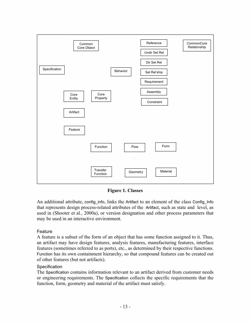
Second, all object and relationship classes, except for the abstract classes and the Information class, have an attribute called type, the value of which is a string that acts as a symbolic classifier. Each object and relationship class may have a distinct hierarchical taxonomy of terms associated with that class. The value of the type attribute would then correspond to one of the terms within the taxonomy for the given class. For example, “convert” is one of numerous types of transfer functions and the term can serve as the type attribute of an instance of the class. Thus, all object and relationship classes in the representation may have their own individual generic engineering classification hierarchies that are independent of any other hierarchy. In the NIST Design Repository project, the typing information and the associated taxonomies provide a standardized vocabulary which facilitates indexing and retrieval of product knowledge for design reuse (Szykman et al., 1999). In an eventual implementation of the core model for production use, the type attributes and their underlying taxonomies may provide an automated means for creating domain-specific specializations of the generic core classes, as discussed in Section 8.1. 6.2. Semantics This section presents brief descriptions of the semantics or meaning of all the classes in the core model shown in Figure 1 ( the seemingly odd placement of the objects in the figure will be clarified in the succeeding figures). Common Core Object This is an abstract class (class with no instances) that is the highest level of generalization of object classes, i.e., all object classes are specialized from it according to the class hierarchy discussed in Section 6.3. Core Entity This is an abstract class from which the classes Artifact and Feature are specialized. Core Property This is another abstract class, from which the classes Function, Flow, Form, Geometry and Material are specialized. Constraints, requirements and assembly relationships, as presented in Section 6.4, may be applied to instances of this class. Artifact The key object class is the Artifact. The Artifact represents a distinct entity in a design, whether that entity is a component, product, subassembly or assembly. All the latter entities can be represented and interrelated through the subartifact/subartifact_of containment hierarchy discussed in Section 6.4. The Artifact’s attributes, other than the common ones described above, refer to the Specification responsible for the Artifact and the Form, Function and Behavior objects comprising the Artifact, i. e., in UML terminology, forming an aggregation with the Artifact.
- 12 -
MaterialGeometryTransfer Function
Form Flow Function
Feature
Artifact
Constraint
Assembly
Requirement
Set Rel’ship
Dir Set Rel
Undir Set Rel
Reference
Core Property
Core Entity
BehaviorSpecification
CommonCore Relationship
Common Core Object
Figure 1. Classes An additional attribute, config_info, links the Artifact to an element of the class Config_Info that represents design process-related attributes of the Artifact, such as state and level, as used in (Shooter et al., 2000a), or version designation and other process parameters that may be used in an interactive environment. Feature A feature is a subset of the form of an object that has some function assigned to it. Thus, an artifact may have design features, analysis features, manufacturing features, interface features (sometimes referred to as ports), etc., as determined by their respective functions. Function has its own containment hierarchy, so that compound features can be created out of other features (but not artifacts). Specification The Specification contains information relevant to an artifact derived from customer needs or engineering requirements. The Specification collects the specific requirements that the function, form, geometry and material of the artifact must satisfy.
- 13 -
Function The artifact’s function represents what the artifact is supposed to do. The artifact satisfies the engineering requirements largely through its function. The term function is often used synonymously with the term intended behavior. Transfer Function Transfer function is a specialized form of function involving the transfer of an input flow into an output flow. Examples of transfer functions are “transmit” a flow of fluid or current, a message, etc., or “convert” from one energy flow to another or from a message to an action. Flow Flow is the medium (fluid, energy, message stream, etc.) that serves as the output of one or more transfer function(s) and the input of one or more other function(s). Each flow is also identified by its source and destination artifacts. Behavior The artifact’s behavior represents how the artifact implements its function. Behavior is governed by engineering principles which are incorporated into a behavior or causal model that explains how the intended function is achieved. Application of the behavior model to the artifact describes or simulates the artifact’s observed behavior based on its form. Form The form of the artifact can be viewed as the proposed design solution for the design problem specified by the function. In the core product model described, the artifact’s physical characteristics are represented in terms of its geometry and material properties. This subdivision was introduced into the core model because some of the intended applications, such as the Design-Process Planning Integration and the Design for Tolerancing projects tend to treat these two aspects quite differently (e. g., the task of material selection for a given function and geometry in process planning). Geometry Geometry is the spatial description of the artifact. Material Material is the description of the internal composition of the artifact. Common Core Relationship This is the abstract class from which all relationship classes are specialized according to the class hierarchy presented in Section 6.3.
- 14 -
Requirement A requirement is a specific element of the specification of an artifact that applies to some aspect of the function, form, geometry or material of the artifact. Conceptually, requirements should only affect the function, i. e., the intended behavior; in practice, some requirements tend to affect the design solution directly, i. e., the form, geometry or material of the artifact. As will be shown in Section 6.5, requirements cannot apply to behavior, which is strictly determined by the behavior model. Constraint A constraint is a specific shared property of a set of entities that must hold in all cases. At the level of the core model, only the entity instances that constitute the constrained set are identified. If it is intended to represent a mathematical equality or inequality constraint, the properties slot of the constraint can store the names of the attributes that enter in the constraint as well as the relational operator linking them. Reference A reference provides a direct means of linking or navigating between two entities. Considering the vast complexity of relationships among entities that can be represented in the model, it was thought prudent to introduce this class. Assembly The assembly relationship between artifacts, i.e., parts, and their assembly features is modeled simply as a set membership relationship among attributes called components. In future applications of the core model these components could be differentiated by roles, for example: source artifact(s); their respective mating feature(s); and the resulting artifact. Set-Relationship This is another abstract class from which the two relationship classes described below are specialized. Undirected Set-Relationship This class sets up a simple set membership relationship among its constituent entities. Directed Set-Relationship This is a set membership relationship consisting of two subsets, one of which is called the special member, in which the two subsets have different roles. For example, a directed set relationship “control” may designate a special member of the set which has the role of “controlling,” while the other members of the set have the role of being “controlled by” that special member. 6.3. Class Hierarchy The class hierarchy is shown in Figure 2.
- 15 -
Common Core Object
CommonCore Relationship
Specification Behavior
Core Entity
Core Property
Reference
Undir Set Rel
Dir Set Rel
Set Rel’ship
Requirement
Assembly
Constraint
Artifact
Feature
Function Flow Form
Transfer Function Geometry Material
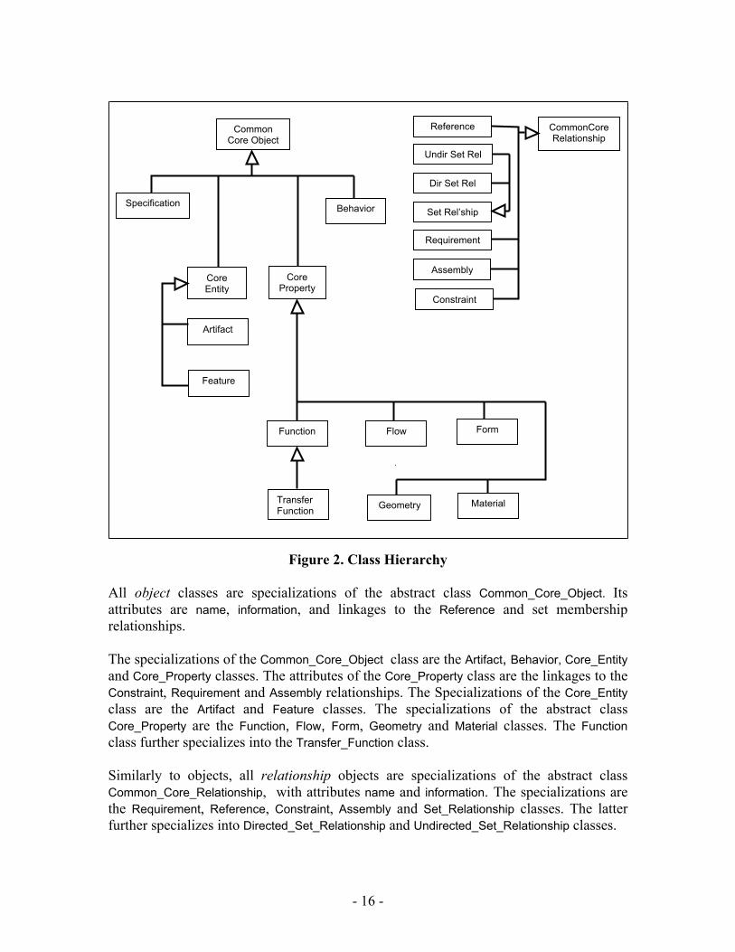
Figure 2. Class Hierarchy All object classes are specializations of the abstract class Common_Core_Object. Its attributes are name, information, and linkages to the Reference and set membership relationships. The specializations of the Common_Core_Object class are the Artifact, Behavior, Core_Entity and Core_Property classes. The attributes of the Core_Property class are the linkages to the Constraint, Requirement and Assembly relationships. The Specializations of the Core_Entity class are the Artifact and Feature classes. The specializations of the abstract class Core_Property are the Function, Flow, Form, Geometry and Material classes. The Function class further specializes into the Transfer_Function class. Similarly to objects, all relationship objects are specializations of the abstract class Common_Core_Relationship, with attributes name and information. The specializations are the Requirement, Reference, Constraint, Assembly and Set_Relationship classes. The latter further specializes into Directed_Set_Relationship and Undirected_Set_Relationship classes.
- 16 -
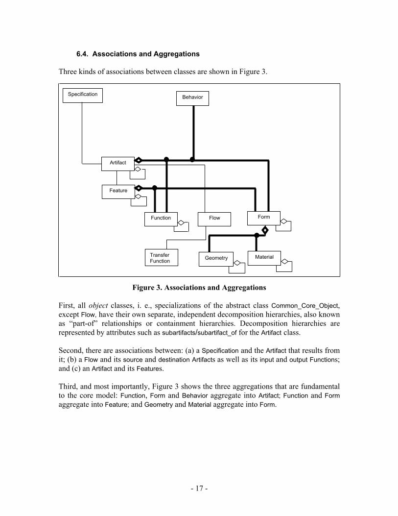
6.4. Associations and Aggregations Three kinds of associations between classes are shown in Figure 3.
Specification
Artifact
Feature
Function Flow Form
Transfer Function Geometry Material
Behavior
Figure 3. Associations and Aggregations First, all object classes, i. e., specializations of the abstract class Common_Core_Object, except Flow, have their own separate, independent decomposition hierarchies, also known as “part-of” relationships or containment hierarchies. Decomposition hierarchies are represented by attributes such as subartifacts/subartifact_of for the Artifact class. Second, there are associations between: (a) a Specification and the Artifact that results from it; (b) a Flow and its source and destination Artifacts as well as its input and output Functions; and (c) an Artifact and its Features. Third, and most importantly, Figure 3 shows the three aggregations that are fundamental to the core model: Function, Form and Behavior aggregate into Artifact; Function and Form aggregate into Feature; and Geometry and Material aggregate into Form.
- 17 -
6.5. Relationships
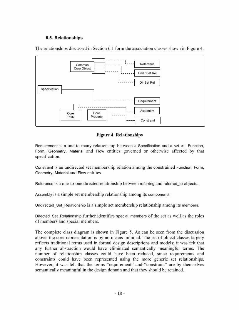
The relationships discussed in Section 6.1 form the association classes shown in Figure 4.
Common Core Object
Core Entity
Core Property
Reference
Undir Set Rel
Dir Set Rel
Requirement
Assembly
Constraint
Specification
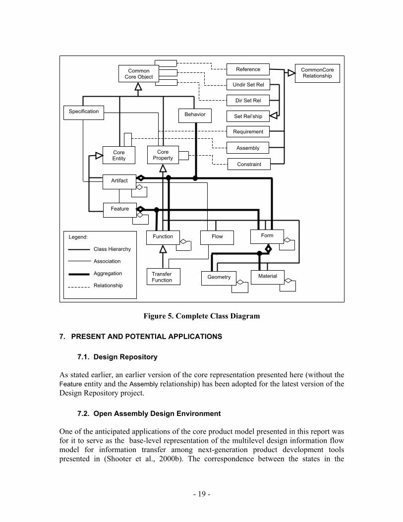
Figure 4. Relationships Requirement is a one-to-many relationship between a Specification and a set of Function, Form, Geometry, Material and Flow entities governed or otherwise affected by that specification. Constraint is an undirected set membership relation among the constrained Function, Form, Geometry, Material and Flow entities. Reference is a one-to-one directed relationship between referring and referred_to objects. Assembly is a simple set membership relationship among its components. Undirected_Set_Relationship is a simple set membership relationship among its members. Directed_Set_Relationship further identifies special_members of the set as well as the roles of members and special members. The complete class diagram is shown in Figure 5. As can be seen from the discussion above, the core representation is by no means minimal. The set of object classes largely reflects traditional terms used in formal design descriptions and models; it was felt that any further abstraction would have eliminated semantically meaningful terms. The number of relationship classes could have been reduced, since requirements and constraints could have been represented using the more generic set relationships. However, it was felt that the terms “requirement” and “constraint” are by themselves semantically meaningful in the design domain and that they should be retained.
- 18 -
Common Core Object
CommonCore Relationship
Specification Behavior
Core Entity
Core Property
Reference
Undir Set Rel
Dir Set Rel
Set Rel’ship
Requirement
Assembly
Constraint
Artifact
Feature
Function Flow Form
Transfer Function Geometry Material
Legend: Class Hierarchy Association Aggregation Relationship
Figure 5. Complete Class Diagram 7. PRESENT AND POTENTIAL APPLICATIONS 7.1. Design Repository As stated earlier, an earlier version of the core representation presented here (without the Feature entity and the Assembly relationship) has been adopted for the latest version of the Design Repository project. 7.2. Open Assembly Design Environment One of the anticipated applications of the core product model presented in this report was for it to serve as the base-level representation of the multilevel design information flow model for information transfer among next-generation product development tools presented in (Shooter et al., 2000b). The correspondence between the states in the
- 19 -
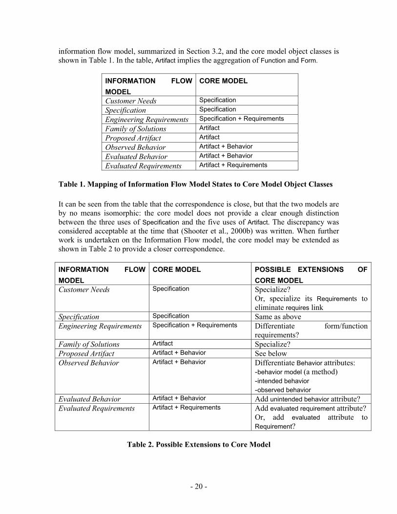
information flow model, summarized in Section 3.2, and the core model object classes is shown in Table 1. In the table, Artifact implies the aggregation of Function and Form.
INFORMATION FLOW MODEL
CORE MODEL
Customer Needs Specification Specification Specification Engineering Requirements Specification + Requirements Family of Solutions Artifact Proposed Artifact Artifact Observed Behavior Artifact + Behavior Evaluated Behavior Artifact + Behavior Evaluated Requirements Artifact + Requirements
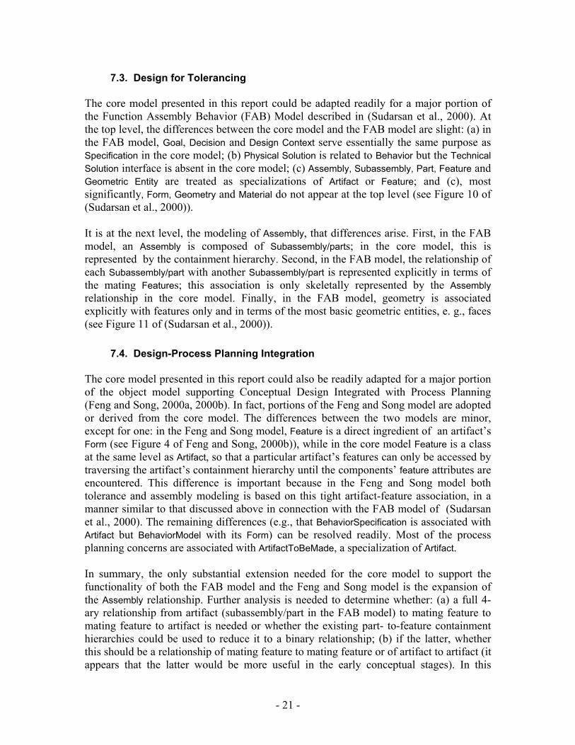
Table 1. Mapping of Information Flow Model States to Core Model Object Classes It can be seen from the table that the correspondence is close, but that the two models are by no means isomorphic: the core model does not provide a clear enough distinction between the three uses of Specification and the five uses of Artifact. The discrepancy was considered acceptable at the time that (Shooter et al., 2000b) was written. When further work is undertaken on the Information Flow model, the core model may be extended as shown in Table 2 to provide a closer correspondence. INFORMATION FLOW MODEL
CORE MODEL POSSIBLE EXTENSIONS OF CORE MODEL
Customer Needs Specification Specialize? Or, specialize its Requirements to eliminate requires link
Specification Specification Same as above Engineering Requirements Specification + Requirements Differentiate form/function
requirements? Family of Solutions Artifact Specialize? Proposed Artifact Artifact + Behavior See below Observed Behavior Artifact + Behavior Differentiate Behavior attributes:
-behavior model (a method) -intended behavior -observed behavior
Evaluated Behavior Artifact + Behavior Add unintended behavior attribute? Evaluated Requirements Artifact + Requirements Add evaluated requirement attribute?
Or, add evaluated attribute to Requirement?
Table 2. Possible Extensions to Core Model
- 20 -
7.3. Design for Tolerancing The core model presented in this report could be adapted readily for a major portion of the Function Assembly Behavior (FAB) Model described in (Sudarsan et al., 2000). At the top level, the differences between the core model and the FAB model are slight: (a) in the FAB model, Goal, Decision and Design Context serve essentially the same purpose as Specification in the core model; (b) Physical Solution is related to Behavior but the Technical Solution interface is absent in the core model; (c) Assembly, Subassembly, Part, Feature and Geometric Entity are treated as specializations of Artifact or Feature; and (c), most significantly, Form, Geometry and Material do not appear at the top level (see Figure 10 of (Sudarsan et al., 2000)). It is at the next level, the modeling of Assembly, that differences arise. First, in the FAB model, an Assembly is composed of Subassembly/parts; in the core model, this is represented by the containment hierarchy. Second, in the FAB model, the relationship of each Subassembly/part with another Subassembly/part is represented explicitly in terms of the mating Features; this association is only skeletally represented by the Assembly relationship in the core model. Finally, in the FAB model, geometry is associated explicitly with features only and in terms of the most basic geometric entities, e. g., faces (see Figure 11 of (Sudarsan et al., 2000)). 7.4. Design-Process Planning Integration The core model presented in this report could also be readily adapted for a major portion of the object model supporting Conceptual Design Integrated with Process Planning (Feng and Song, 2000a, 2000b). In fact, portions of the Feng and Song model are adopted or derived from the core model. The differences between the two models are minor, except for one: in the Feng and Song model, Feature is a direct ingredient of an artifact’s Form (see Figure 4 of Feng and Song, 2000b)), while in the core model Feature is a class at the same level as Artifact, so that a particular artifact’s features can only be accessed by traversing the artifact’s containment hierarchy until the components’ feature attributes are encountered. This difference is important because in the Feng and Song model both tolerance and assembly modeling is based on this tight artifact-feature association, in a manner similar to that discussed above in connection with the FAB model of (Sudarsan et al., 2000). The remaining differences (e.g., that BehaviorSpecification is associated with Artifact but BehaviorModel with its Form) can be resolved readily. Most of the process planning concerns are associated with ArtifactToBeMade, a specialization of Artifact. In summary, the only substantial extension needed for the core model to support the functionality of both the FAB model and the Feng and Song model is the expansion of the Assembly relationship. Further analysis is needed to determine whether: (a) a full 4-ary relationship from artifact (subassembly/part in the FAB model) to mating feature to mating feature to artifact is needed or whether the existing part- to-feature containment hierarchies could be used to reduce it to a binary relationship; (b) if the latter, whether this should be a relationship of mating feature to mating feature or of artifact to artifact (it appears that the latter would be more useful in the early conceptual stages). In this
- 21 -
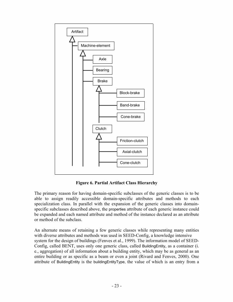
connection, it should also be ascertained whether the Assembly, Subassembly, Part hierarchy should be implemented by specialization of the Artifact class in addition to the artifact containment hierarchy provided by the core model. 8. AREAS FOR FUTURE RESEARCH 8.1. Extensions to Support of Interoperable Tools As described in Section 6.1, the core model presented here adopts two techniques from the Design Repository project so as to make the model compact and generic: (a) the use of the type attribute for classification of entities; and (b) the use of the property attribute of the Information entity associated with each class to store an object's attributes as a string of attribute-value pairs. These techniques stemmed from the objectives of the Design Repository project, i. e., the storage and retrieval of archival information rather than the support of interactive product development. The benefit of these techniques is the generic nature of the class hierarchy that allows the representation of a broad number of concepts without specialization into a large number of subclasses. The lack of specialization is a benefit at the representation level in terms of simplicity, but may be expected to be unsuitable as a mode of information transfer between tools where rapid and seamless interoperation is needed. There are a number of ways by which these limitations may be removed. The type taxonomies developed by the Design Repository project may be used to generate, automatically or semi-automatically, domain-specific specializations of the generic classes in the core model. As an illustration, Table 3 shows a small subset of the taxonomy of Artifacts that arose in the modeling of the current set of example repositories, without any specific attempt at a comprehensive artifact taxonomy. Figure 6 shows the class hierarchy structure generated in a one-to-one correspondence with the classifiers in the taxonomy tree. Similar class hierarchy structures may be generated as needed for the other generic object classes, e. g., Function, Form and Behavior.
Artifact Machine-element …
Axle … Bearing … Brake
Block-brake Band-brake Cone-brake …
Clutch Friction-clutch Axial-clutch Cone-clutch …
Table 3. Partial Taxonomy of Artifacts
- 22 -
Axle
Bearing
Brake
Machine-element
Block-brake
Band-brake
Cone-brake
Clutch
Friction-clutch
Axial-clutch
Cone-clutch
Artifact
Figure 6. Partial Artifact Class Hierarchy The primary reason for having domain-specific subclasses of the generic classes is to be able to assign readily accessible domain-specific attributes and methods to each specialization class. In parallel with the expansion of the generic classes into domain-specific subclasses described above, the properties attribute of each generic instance could be expanded and each named attribute and method of the instance declared as an attribute or method of the subclass. An alternate means of retaining a few generic classes while representing many entities with diverse attributes and methods was used in SEED-Config, a knowledge intensive system for the design of buildings (Fenves et al., 1999). The information model of SEED-Config, called BENT, uses only one generic class, called BuildingEntity, as a container (i. e., aggregation) of all information about a building entity, which may be as general as an entire building or as specific as a beam or even a joint (Rivard and Fenves, 2000). One attribute of BuildingEntity is the buildingEntityType, the value of which is an entry from a
- 23 -
hierarchical taxonomy of building entity types known to the system, in a manner analogous to the type attributes in the Design Repository. Some slots of the BuildingEntity are common to all building entity types, e. g., the entity’s spatial representation (geometry), its classifiers (all symbol valued attributes are treated as classifiers) and its derivation (the sequence of productions that produced the current state of the artifact’s description). More specific attributes are grouped into three sets: Function Units, analogous to Requirements and Function in the core model, describing the design requirements; Design Units, analogous to Form, describing the proposed solution; and Evaluation Units, analogous to Behavior, describing the evaluation results. Each unit consists of one or more source-coherent attributes, typically the attributes resulting from the application of one production, e.g., “loads” in a Functional Unit or “steel properties” in a Design Unit. The BuildingEntityType acts as an internal classifier that determines what types of Units can be assigned to a building entity of a given type. Extending the core model in a manner similar to that used in the BENT model would present no conceptual difficulties. The only distinction from the first specialization method discussed above is that instead of actually generating specialization subclasses with their explicit domain-specific attributes, the type taxonomies would be used to designate the sets of attributes to be aggregated to the generic classes. 8.2. Exploration of Applicability to Full Lifecycle of Artifact All of the studies that contributed to the development of the core product model have dealt with the early, conceptual phases of design. It is in these phases that the design of the emerging artifact is most directly influenced by the requirements and that the function and form of the artifact are dealt with equal emphasis. The core model directly facilitates reasoning with these concepts by means of the associations, aggregations and named relationships provided. One of the anonymous reviewers of (Shooter et al., 2000a) questioned whether the design information flow model, summarized in Section 3.2, is applicable to the later, detailed design development phases. Since the core product model is envisaged as the base level support of the design information flow model, as discussed in Section 7.2, the same question is appropriate for the core model as well. The core model is sufficiently generic that it should be applicable to the full lifecycle of the artifact beyond design to manufacturing, distribution and recycling. Admittedly, detailed design development introduces a great deal of detail in the artifact description, not all of it necessarily tied to user requirements, function or even behavior. This information can be readily captured in the core model through unlimited recursion in the containment hierarchies of the Artifact and its Form. Nevertheless, the applicability of the core model for such use has neither been demonstrated nor tested, and must therefore be treated as an open research question. Alternately, as indicated in Section 3.1, the core model may be used only in the conceptual design phases, with the resulting design description translated to more robust, tested information exchange representations, e. g., STEP.
- 24 -
The final significant area of future work is to gather feedback and buy-in from both researchers and end-users of tools interoperating by means of a representation based on the core model. 9. SUMMARY This report presents a core representation for design information that is intended to serve as a representational foundation for next-generation product development systems. The development of this core representation was motivated by a vision of next-generation product development systems, drew specific content-level requirements from a closely related effort in design information flow modeling, and was synthesized after an analysis of several independently-developed design artifact representations. This research is one attempt to provide a foundation for next-generation tools by means of a simple and generic representation infrastructure. Clearly, automated reasoning will be easier using formally-represented product information than using informal or unstructured information. The structure of product information that is captured, such as physical decomposition, functional decomposition, and mappings between the two, will further support reasoning about designs. The development of extensive taxonomies of engineering terminology (an ongoing activity in the NIST Design Repository project) for use with the type classification attribute will greatly facilitate the indexing and retrieval of product information from engineering databases. ACKNOWLEDGEMENTS The author thanks Ram Sriram for suggesting the topic; his co-authors on (Shooter et al., 2000a) and (Shooter et al., 2000b), Simon Szykman, Walid Keirouz and Steven B. Shooter, for providing the global context for the core model and many iterations of discussions; R. Sudarsan for many helpful discussions on modeling; Simon Szykman, R. Sudarsan, Shaw Feng and Jaideep Ganguly, for contributing the individual product models that merged into the common core model; Jocelyn Senfaute for assistance in refining and maintaining the information model; and, foremost, Fujun Wang for assistance in developing the UML model and its Java implementation. DISCLAIMER No approval or endorsement of any commercial product, service or company by the National Institute of Standards and Technology is intended or implied.
- 25 -
REFERENCES
Alberts L.K. and F. Dikker (1992), “Integrating Standards and Synthesis Knowledge Using the YMIR Ontology,” Artificial Intelligence in Design ‘94, J.S. Gero and F. Sudweeks (Eds.), Kluwer Academic Publishers, Boston, pp. 517-534. Angster, S., K. Lyons, P. Hart, and S. Jayaram (1998). “Interoperability of Assembly Analysis Applications Through the Use of the Open Assembly Design Environment,” Proceedings of DETC98, 1998 ASME Design Engineering Technical Conference.
Bliznakov, P. I., J. J. Shah, and S. D. Urban (1996), “Integration Infrastructure to Support Concurrence and Collaboration in Engineering Design,” Proceedings of the 1996 ASME Design Engineering Technical Conferences and Computers in Engineering Conference, Paper No. 96-DETC/EIM-1420.
Booch, G., J. Rumbaugh, and I. Jacobson (1999), The Unified Modeling Language User Guide, Addison-Wesley, Reading, Massachusetts.
Chandrasekaran, B., A. Goel, and Y. Iwasaki (1993), “Functional Representation as Design Rationale,” IEEE Computer, pp. 48-56.
Chen, P. P.(1976), “The Entity-Relationship Model: Toward a Unified View of Data”, ACM Transactions on Database Systems, Vol. 1, No. I, pp. 9-36.
de Kleer, J. and J. S. Brown (1983), “Assumptions and Ambiguities in Mechanistic Mental Models,” Mental Models, D. Gentner and A. L. Stevens (Eds.), Lawrence Erlbaum Associates, New Jersey, pp. 155-190.
Feng, S. C., W. W. Nederbragt, S. Kaing, and R. D. Sriram (1999) “Incorporating Process Planning into Conceptual Design,” Proceedings of the 1999 ASME Design Engineering Technical Conferences (4th Design for Manufacturing Conference), Paper No. DETC99/DFM-8922.
Feng, S. C. and E. Y. Song (2000a), “Information Modeling of Conceptual Process Planning Integrated with Conceptual Design,” Proceedings of the 2000 ASME Design Engineering Technical Conferences (5th Design for Manufacturing Conference), Paper No. DETC2000/DFM-14009.
Feng, S. C. and E. Y. Song (2000b), “Information Modeling of Conceptual Design Integrated with Conceptual Process Planning,” Proceedings of the 2000 ASME International Mechanical Congress and Exposition.
Fenves, S. J., H. Rivard and N. Gomez (1999), “SEED-Config: A Tool for Conceptual Structural Design in a Collaborative Building Design Environment”, special issue on "Collaborative and Concurrent Engineering in the Construction Industry," Artificial Intelligence in Engineering, to appear.
- 26 -
Goel, A., S. Bhatta, and E. Stroulia (1996), “KRITIK: An Early Case-Based Design System,” Issues and Applications of Case-Based Reasoning to Design, M. Maher and P. Pu (Eds.), Lawrence Erlbaum Associates, New Jersey.
Goel, A., A. Gomez, N. Grue, J. W. Murdock, M. Recker, and T. Govindaraj (1996), “Explanatory Interface in Interactive Design Environments,” Artificial Intelligence in Design ‘96, J. S. Gero (Ed.), Kluwer Academic Publishers, Boston.
Gorti S. R., G. J. Gupta, G. J. Kim, R. D. Sriram, and A. Wong (1998), “An Object-Oriented Representation for Product and Design Process,” Computer-Aided Design, Vol. 30, No. 7, pp. 489-501.
Hardwick, M. and D. Loffredo (1995), “Using EXPRESS to Implement Concurrent Engineering Databases,” Proceedings of the 1995 ASME Computers in Engineering Conference and Engineering Database Symposium, pp. 1069-1083.
Henson, B., N. Juster and A. de Pennington (1994), “Towards an Integrated Representation of Function, Behavior and Form,” Computer Aided Conceptual Design, Proceedings of the 1994 Lancaster International Workshop on Engineering Design, Sharpe J. and V. Oh (eds.), Lancaster University EDC, pp. 95-111.
ISO 10303-1:1994 (1994a), Industrial Automation Systems and Integration – Product Data Representation and Exchange – Part 1: Overview and Fundamental Principles.
Iwasaki Y. and B. Chandrasekaran (1992), “Design Verification through Function and Behavior-Oriented Representations: Bringing the Gap between Function and Behavior,” Artificial Intelligence in Design ‘92, J.S. Gero (Ed.), Kluwer Academic Publishers, Boston, pp. 597-616.
Kemmerer, S. J. (1999), “STEP: The Grand Experience,” NIST Special Publication 939.
Kim, T. S., S.-H. Han, and Y. J. Shin (1996), “Product Data Management Using AP203 of STEP Standard,” Proceedings of the 1996 ASME Design Engineering Technical Conferences and Computers in Engineering Conference, Paper No. 96-DETC/DAC-1069.
Lyons, K., S. Shooter, W. Keirouz and P. Hart (1999), “The Open Assembly Design Environment: An Architecture for Design Agent Interoperability,” Proceedings of the 1999 ASME Design Technical Conference, Paper No. DETC99/DFM-8945.
PDES (1999), “STEP Success Stories,” PDES, Inc. presentation, available online at <http://pdesinc.aticorp.org/success_stories.ppt>.
Qian L. and J. S. Gero (1996), “Function-Behavior-Structure Paths and Their Role in Analogy-Based Design,” Artificial Intelligence for Engineering Design, Analysis and Manufacturing, Vol. 10, No. 4, pp. 289-312.
- 27 -
Ranta, M., M. Mäntylä, Y. Umeda and T. Tomiyama (1996), “Integration of Functional and Feature-Based Product Modelling – the IMS/GNOSIS Experience,” Computer-Aided Design, Vol. 28, No. 5, pp. 371-381.
Rivard, H., and S. J. Fenves (2000), “A Representation of Conceptual Building Designs”, Journal of Computing in Civil Engineering, American Society of Civil Engineers, Vol. 14, No. 3, pp. 151-159.
Roy, U., R. Sudarsan, R. D. Sriram, K. W. Lyons, and M.R. Duffey (1999), “Information Architecture for Design Tolerancing: From Conceptual to the Detail Design,” Proceedings of the 1999 ASME Design Engineering Technical Conferences (25th Design Automation Conference), Paper No. DETC99/DAC-8704.
Shah, J. J., D. K. Jeon, S. D. Urban, P. Bliznakov, and M. Rogers (1996), “Database Infrastructure for Supporting Engineering Design Histories,” Computer-Aided Design, Vol. 28, No. 5, pp. 347-360.
Shooter, S. B., W. Keirouz, S. Szykman, and S. Fenves (2000a), “A Model for the Flow of Design Information,” submitted to Engineering with Computers.
Shooter, S. B., W. Keirouz, S. Szykman, and S. Fenves (2000b), “A Foundation for Interoperability in Next-generation Product Development Systems,” submitted to Computer-Aided Design.
Stokes, M. (Editor) (2001), Managing Engineering Knowledge: MOKA Methodology for Knowledge Based Engineering Applications, MOKA Consortium, London.
Sudarsan, R., U. Roy, Y. Narahari, R. D. Sriram, K. W. Lyons and N. Pramanik (2000), “Information Models for Design Tolerancing: From Conceptual to Detailed Design,” NISTIR 6524.
Szykman, S., J. W. Racz and R. D. Sriram (1999), “The Representation of Function in Computer-based Design,” Proceedings of the 1999 ASME Design Engineering Technical Conferences (11th International Conference on Design Theory and Methodology), Paper No. DETC99/DTM-8742.
Szykman, S., J. W. Racz, C. Bochenek and R. D. Sriram (2000), “A Web-based System for Design Artifact Modeling,” Design Studies, Vol. 21, No. 2.
Umeda, Y., M. Ishii, M. Yoshioka, Y. Shimomura and T. Tomiyama (1996), “Supporting Conceptual Design Based on the Function-Behavior-State Modeler,” Artificial Intelligence for Engineering Design, Analysis and Manufacturing, Vol. 10, pp. 275-288.
Wong A. and R. D. Sriram (1993), “SHARED: An Information Model for Cooperative Product Development,” Research in Engineering Design, Vol. 5, No. 1, pp. 21-39.
- 28 -
Wood III, W. H. and A. M. Agogino (1996), “Case-Based Conceptual Design Information Server for Concurrent Engineering,” Computer-Aided Design, Vol. 28, No. 5, pp. 361-370.
- 29 -
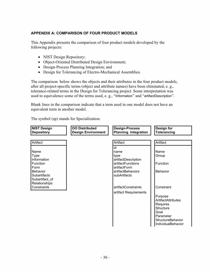
APPENDIX A: COMPARISON OF FOUR PRODUCT MODELS This Appendix presents the comparison of four product models developed by the following projects:
• NIST Design Repository; • Object-Oriented Distributed Design Environment; • Design-Process Planning Integration; and • Design for Tolerancing of Electro-Mechanical Assemblies.
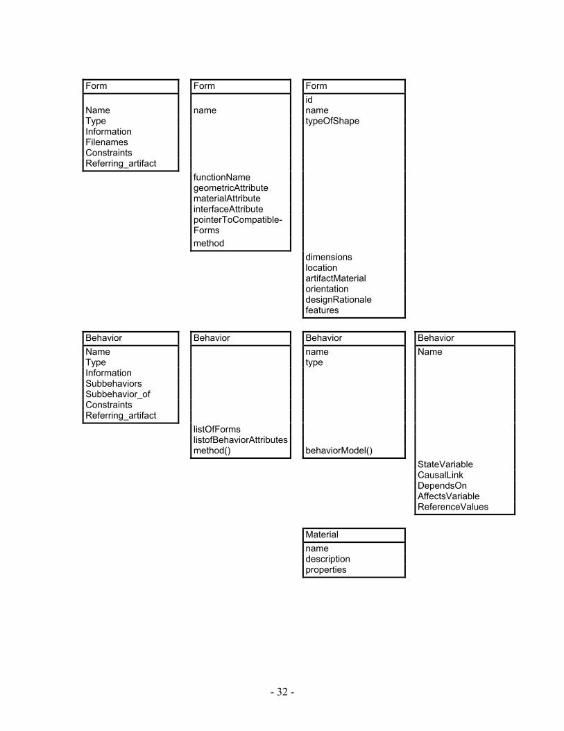
The comparison below shows the objects and their attributes in the four product models, after all project-specific terms (object and attribute names) have been eliminated, e. g., tolerance-related terms in the Design for Tolerancing project. Some interpretation was used to equivalence some of the terms used, e. g., “Information” and “artifactDescription”. Blank lines in the comparison indicate that a term used in one model does not have an equivalent term in another model. The symbol (sp) stands for Specialization. NIST Design OO Distributed Design-Process Design for Depository Design Environment Planning Integration Tolerancing Artifact Artifact Artifact id Name name Name Type type Group Information artifactDescription Function artifactFunctions Function Form artifactForm Behavior artifactBehaviors Behavior Subartifacts subArtifacts Subartifact_of Relationships Constraints artifactConstraints Constraint artifact Requirements Purpose ArtifactAttributes Requires Structure Goal Parameter StructureBehavior IndividualBehavior
- 30 -
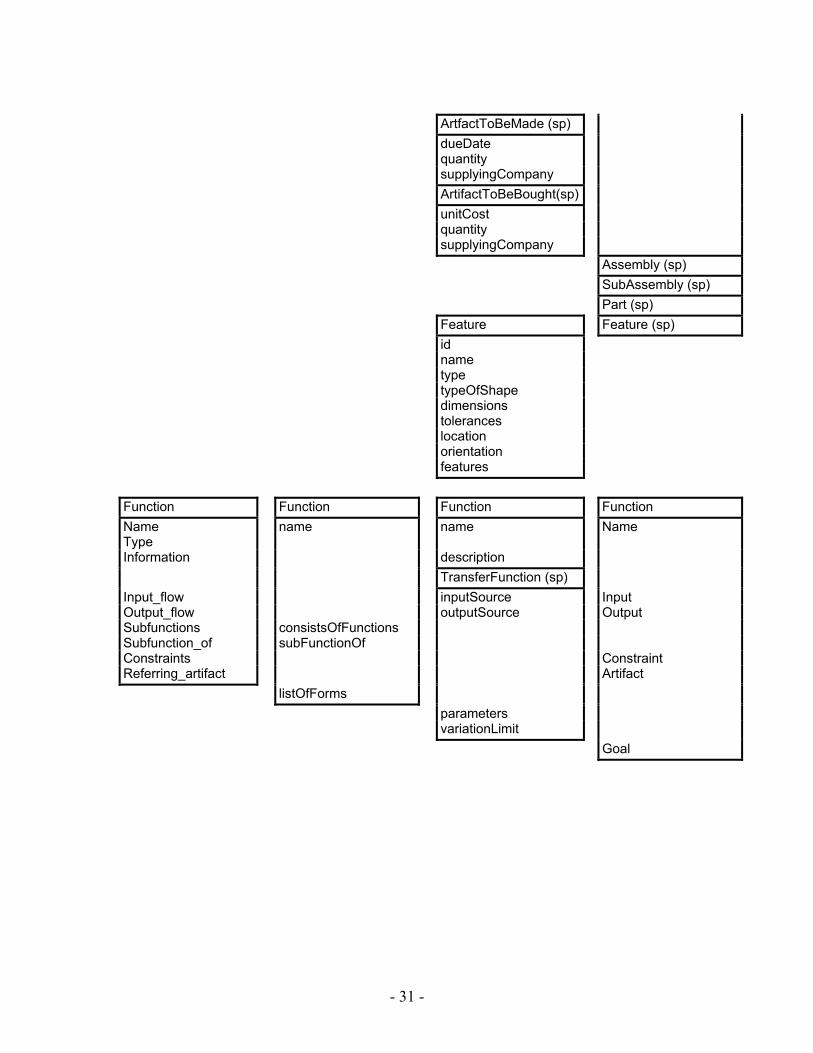
ArtfactToBeMade (sp) dueDate quantity supplyingCompany ArtifactToBeBought(sp) unitCost quantity supplyingCompany Assembly (sp) SubAssembly (sp) Part (sp) Feature Feature (sp) id name type typeOfShape dimensions tolerances location orientation features Function Function Function Function Name name name Name Type Information description TransferFunction (sp) Input_flow inputSource Input Output_flow outputSource Output Subfunctions consistsOfFunctions Subfunction_of subFunctionOf Constraints Constraint Referring_artifact Artifact listOfForms parameters variationLimit Goal
- 31 -
Form Form Form id Name name name Type typeOfShape Information Filenames Constraints Referring_artifact functionName geometricAttribute materialAttribute interfaceAttribute pointerToCompatible-
Forms
method dimensions location artifactMaterial orientation designRationale features Behavior Behavior Behavior Behavior Name name Name Type type Information Subbehaviors Subbehavior_of Constraints Referring_artifact listOfForms listofBehaviorAttributes method() behaviorModel() StateVariable CausalLink DependsOn AffectsVariable ReferenceValues Material name description properties
- 32 -
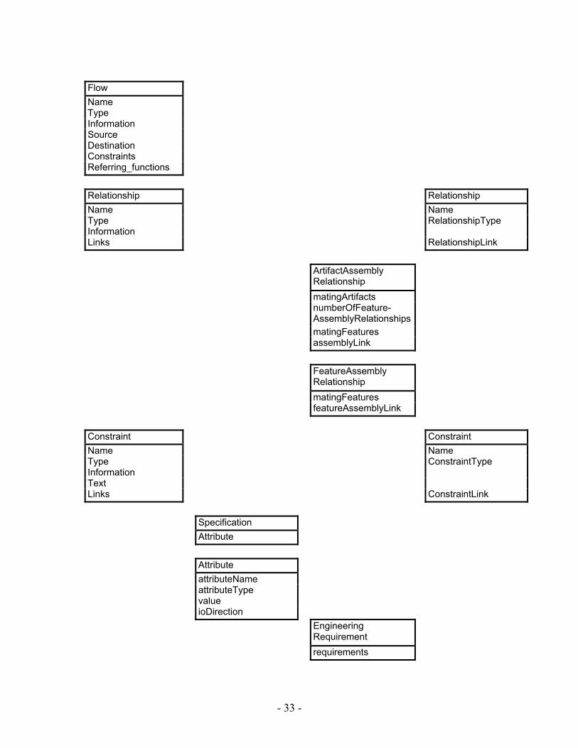
Flow Name Type Information Source Destination Constraints Referring_functions Relationship Relationship Name Name Type RelationshipType Information Links RelationshipLink ArtifactAssembly
Relationship
matingArtifacts numberOfFeature-
AssemblyRelationships
matingFeatures assemblyLink FeatureAssembly
Relationship
matingFeatures featureAssemblyLink Constraint Constraint Name Name Type ConstraintType Information Text Links ConstraintLink Specification Attribute Attribute attributeName attributeType value ioDirection Engineering
Requirement
requirements
- 33 -
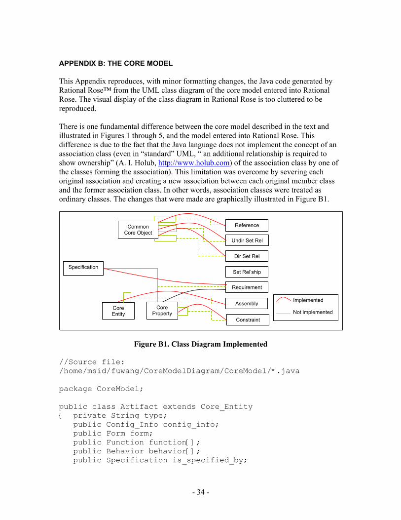
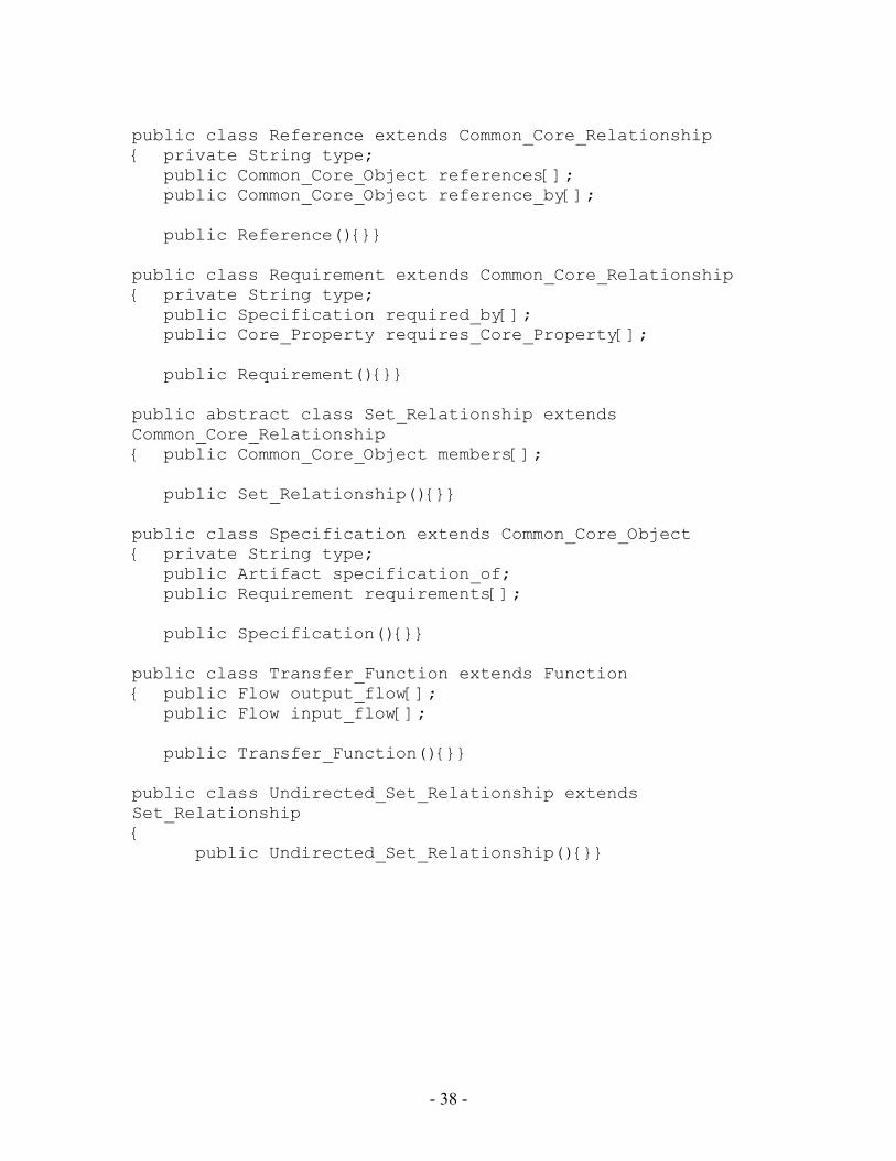
APPENDIX B: THE CORE MODEL This Appendix reproduces, with minor formatting changes, the Java code generated by Rational Rose™ from the UML class diagram of the core model entered into Rational Rose. The visual display of the class diagram in Rational Rose is too cluttered to be reproduced. There is one fundamental difference between the core model described in the text and illustrated in Figures 1 through 5, and the model entered into Rational Rose. This difference is due to the fact that the Java language does not implement the concept of an association class (even in “standard” UML, “ an additional relationship is required to show ownership” (A. I. Holub, http://www.holub.com) of the association class by one of the classes forming the association). This limitation was overcome by severing each original association and creating a new association between each original member class and the former association class. In other words, association classes were treated as ordinary classes. The changes that were made are graphically illustrated in Figure B1.
Implemented Not implemented
Common Core Object
Core Entity
Core Property
Reference
Undir Set Rel
Dir Set Rel
Set Rel’ship
Requirement
Assembly
Constraint
Specification
Figure B1. Class Diagram Implemented //Source file: /home/msid/fuwang/CoreModelDiagram/CoreModel/*.java package CoreModel; public class Artifact extends Core_Entity { private String type; public Config_Info config_info; public Form form; public Function function[]; public Behavior behavior[]; public Specification is_specified_by;
- 34 -
public Flow is_source_of[]; public Flow is_destination_of[]; public CoreModel.Artifact subartifact_of[]; public CoreModel.Artifact subartifacts[]; public Feature features[]; public Artifact(){}} public class Assembly extends Common_Core_Relationship { private String type; public Core_Entity components[]; public Assembly(){}} public class Behavior extends Common_Core_Object { private String type; public Artifact behavior_of_artifact; public CoreModel.Behavior subbehaviors[]; public CoreModel.Behavior subbehavior_of; public Behavior(){}}} public abstract class Common_Core_Object { private String name; public Information information; public Reference referenced_by[]; public Reference references[]; public Set_Relationship member_of[]; public Directed_Set_Relationship special_member_of[]; public Common_Core_Object(){}} public abstract class Common_Core_Relationship { private String name; public Information information; public Common_Core_Relationship(){}} public class Config_Info { private String name; private String type; public Information information; public Artifact config_info_of_artifact; public Config_Info(){}}
- 35 -
public class Constraint extends Common_Core_Relationship { private String type; public Core_Property constrains[]; public Constraint(){}} public abstract class Core_Entity extends Common_Core_Object { public Assembly component_of[]; public Core_Entity(){}} public abstract class Core_Property extends Common_Core_Object { public Constraint constrained_by[]; public Requirement required_by_requirement[]; public Core_Property(){}} public class Directed_Set_Relationship extends Set_Relationship { private String type; private String special_member_role; private String member_role; public Common_Core_Object special_members[]; public Directed_Set_Relationship(){}} public class Feature extends Core_Entity { private String type; public Artifact feature_of_artifact; public Function function_of_feature[]; public Form form_of_feature; public CoreModel.Feature subfeature_of; public CoreModel.Feature subfeatures[]; public Feature(){}} public class Flow extends Core_Property { private String type; public Artifact is_source_of[]; public Artifact is_destination_of[]; public Transfer_Function input_flow[]; public Transfer_Function output_flow[]; public Flow(){}}
- 36 -
public class Form extends Core_Property { private String type; public Material material; public Geometry geometry; public Artifact form_of_artifact; public Feature form_of_feature; public CoreModel.Form subforms[]; public CoreModel.Form subform_of; public Form(){}} public class Function extends Core_Property { private String type; public Artifact function_of_artifact; public Feature function_of_feature; public CoreModel.Function subfunctions[]; public CoreModel.Function subfunction_of; public Function(){}} public class Geometry extends Core_Property { private String type; public Form geometry_of_form; public CoreModel.Geometry subgeometries[]; public CoreModel.Geometry subgeometry_of; public Geometry(){}} public class Information { private String name; private String description; private String documentation; private String methods; private String properties; public Information(){}} public class Material extends Core_Property { private String type; public Form material_of_form; public CoreModel.Material submaterials[]; public CoreModel.Material submaterial_of; public Material(){}}
- 37 -
- 38 -
public class Reference extends Common_Core_Relationship { private String type; public Common_Core_Object references[]; public Common_Core_Object reference_by[]; public Reference(){}} public class Requirement extends Common_Core_Relationship { private String type; public Specification required_by[]; public Core_Property requires_Core_Property[]; public Requirement(){}} public abstract class Set_Relationship extends Common_Core_Relationship { public Common_Core_Object members[]; public Set_Relationship(){}} public class Specification extends Common_Core_Object { private String type; public Artifact specification_of; public Requirement requirements[]; public Specification(){}} public class Transfer_Function extends Function { public Flow output_flow[]; public Flow input_flow[]; public Transfer_Function(){}} public class Undirected_Set_Relationship extends Set_Relationship { public Undirected_Set_Relationship(){}}