Embed Size (px)
Citation preview

FORECAST ENGINEERING – FROM PAST DESIGN TO FUTURE DECISION 2016
1
A distributed-collaborative modal identification procedure for wireless structural health monitoring systems
Amro Nasr1, Fataneh Dehshahri2, Cristian Vasile Miculaş3, Kata Ficker4, Sahar Azari1,
Hamidullah Afghan1, Kosmas Dragos1, and Kay Smarsly1
1Bauhaus University Weimar, Germany 2Sharif University of Technology, Iran
3Technical University of Cluj-Napoca, Romania 4Budapest University of Technology and Economics, Hungary
Abstract
Structural health monitoring (SHM) has been increasingly employed to ensure public safety and integrity of the built environment. Wireless sensor networks, owing to their lower cost and ease of installation as compared to traditional cable-based systems, have been adopted to ensure the integrity of the structures. Due to the limited power resources of wireless sensor nodes, embedded algorithms are devised to exploit the inherent processing capabilities of the sensor nodes through on-board data processing, in an attempt to reduce the power-consuming wireless data transmission. In this paper, a wireless SHM system capable of distributed-collaborative modal identification is presented, using embedded algorithms. Modal identification in the proposed SHM system is based on the on-board selection of modal “candidate” peaks from the frequency spectra of acceleration response data from a monitored structure. The candidate peaks are sent to a central server, where the final peaks are selected and sent to the sensor nodes in order to retrieve the corresponding Fourier values for modal extraction. The wireless SHM system is validated through laboratory tests on a steel frame structure, showcasing the ability of the SHM system to yield accurate mode shapes regardless of the structural state. The SHM system has been designed and implemented within a summer school project at Bauhaus University Weimar. Keywords: Structural health monitoring, wireless sensor networks, embedded algorithms, experimental modal analysis, frequency domain decomposition. Introduction
Structural health monitoring (SHM) has been increasingly employed to ensure public safety and integrity of the built environment, such as buildings, bridges, pipelines, roads, and tunnels, which are exposed to operational and environmental loads over decades of service. Wireless sensor networks, owing to their lower cost and ease of installation as compared to traditional cable-based systems, are adopted to ensure the integrity of the structures. SHM is used in several engineering fields for conducting condition-based maintenance instead of conventional scheduled maintenance (Semperlotti, 2009). The rapid advancements in computer science and sensor technologies have paved the way for applying wireless sensor networks for SHM, offering easier and lower-cost installations, as opposed to traditional cable-based systems.
Due to the aforementioned benefits of wireless sensor networks, wireless sensor nodes have been increasingly adopted in SHM applications. However, the limited power autonomy and the restricted resources of wireless sensor nodes still pose non-negligible operational constraints. It has been reported that the most power-consuming operation of sensor nodes is due to wireless data transmission (Lei et al., 2010). As a result, embedded computing is
FORECAST ENGINEERING – FROM PAST DESIGN TO FUTURE DECISION 2016
2
employed in wireless SHM systems in an attempt to execute monitoring tasks on-board the sensor nodes and reduce data transmission.
Several approaches towards embedded models and embedded algorithms for wireless sensor nodes have been proposed. Zimmerman et al. (2008) have presented embedded algorithms for output-only system identification. The use of a linear quadratic regulation algorithm for structural control has been proposed by Wang et al. (2006) and Kane et al. (2014). Dragos and Smarsly (2015, 2016) have presented embedding numerical models into wireless sensor nodes for structural health monitoring and decentralized infrastructure health monitoring.
In this paper, a wireless SHM system with modal identification capabilities is presented. First, the mathematical background on modal identification is provided. Second, the architecture of the wireless SHM system is presented and the embedded algorithms are illustrated. Finally, laboratory tests for validation of the proposed SHM system are presented and an outlook on future research is given. Frequency domain decomposition
The extraction of mode shapes in this study is based on frequency domain decomposition (FDD) (Brincker et al., 2000). In FDD, first, the response time histories of all sets of collected acceleration response data (from all measured locations of the monitored structure) are transformed from the time domain into the frequency domain using the fast Fourier transform (FFT) (Cooley and Tukey, 1965). From the Fourier spectrum the highest peaks corresponding to resonant vibration, which are therefore indicative of modes of vibration, are then picked by a peak-picking algorithm. Then, the spectral density matrix, indicative of the power carried by each acceleration response data set, at the frequencies corresponding to the selected peaks is calculated using Eq. 1.
r
i
r
jjiij FF
1 1
G (1)
In Eq. 1, G is the spectral density matrix and F is the complex Fourier value, while r is the number of acceleration response data sets. The overbar and the star denote complex conjugate. The relationship between the input spectral density matrix and the output spectral density matrix is shown in Eq. 2.
Hxy ii HGHG (2)
In Eq. 2, Gy is the output spectral density matrix, Gx is the input spectral density matrix, H is the frequency response function between the input and the output, ω is the eigenfrequency of the selected peak, while the superscript H denotes complex conjugate and transpose (Hermitian). Assuming white noise excitation, the input spectral density matrix is constant. Therefore, according to Brincker et al., the singular value decomposition (SVD) of the output spectral density matrix yields a diagonal matrix holding the eigenvalues, and a left-singular matrix whose left-most vector, at an eigenfrequency corresponding to a resonant peak, is equivalent to the eigenvector of the structure, as shown in Eq. 3.
T
y USUG jrj uuU 1 pjp φu 1 (3)
where U is the left-singular matrix, S is the diagonal matrix holding the eigenvalues, u is the singular vector, p is the index of the selected peak, and φ is the mode shape vector.
FORECAST ENGINEERING – FROM PAST DESIGN TO FUTURE DECISION 2016
3
A wireless SHM system for distributed-collaborative modal identification
A wireless SHM system to perform distributed-collaborative modal identification is presented. First, the overall SHM system is described. Then the implementation of the modal identification tasks in terms of embedded algorithms is illustrated. Description of the wireless SHM system
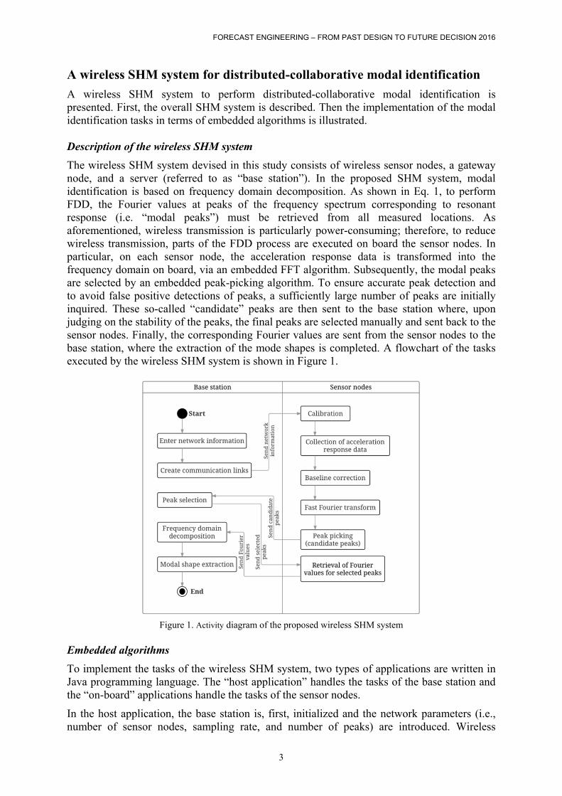
The wireless SHM system devised in this study consists of wireless sensor nodes, a gateway node, and a server (referred to as “base station”). In the proposed SHM system, modal identification is based on frequency domain decomposition. As shown in Eq. 1, to perform FDD, the Fourier values at peaks of the frequency spectrum corresponding to resonant response (i.e. “modal peaks”) must be retrieved from all measured locations. As aforementioned, wireless transmission is particularly power-consuming; therefore, to reduce wireless transmission, parts of the FDD process are executed on board the sensor nodes. In particular, on each sensor node, the acceleration response data is transformed into the frequency domain on board, via an embedded FFT algorithm. Subsequently, the modal peaks are selected by an embedded peak-picking algorithm. To ensure accurate peak detection and to avoid false positive detections of peaks, a sufficiently large number of peaks are initially inquired. These so-called “candidate” peaks are then sent to the base station where, upon judging on the stability of the peaks, the final peaks are selected manually and sent back to the sensor nodes. Finally, the corresponding Fourier values are sent from the sensor nodes to the base station, where the extraction of the mode shapes is completed. A flowchart of the tasks executed by the wireless SHM system is shown in Figure 1.
Figure 1. Activity diagram of the proposed wireless SHM system
Embedded algorithms
To implement the tasks of the wireless SHM system, two types of applications are written in Java programming language. The “host application” handles the tasks of the base station and the “on-board” applications handle the tasks of the sensor nodes.
In the host application, the base station is, first, initialized and the network parameters (i.e., number of sensor nodes, sampling rate, and number of peaks) are introduced. Wireless
FORECAST ENGINEERING – FROM PAST DESIGN TO FUTURE DECISION 2016
4
communication links are established based on the IEEE address of the sensor nodes, and the network parameters are transmitted over the air to the sensor nodes. Upon receiving the candidate modal peaks from the sensor nodes, the host application displays the respective indices of the peaks corresponding to the data series of the frequency spectra. Then, the final peaks are entered interactively into the host application and wirelessly communicated to the sensor nodes. Finally, upon receiving the complex Fourier values of the final peaks from the sensor nodes, the host application performs frequency domain decomposition to extract the mode shapes, employing Java classes from the JAMA library for matrix operations and singular value decomposition (JAMA, 2010).
In the on-board application, the wireless sensors nodes are, first, initialized and calibrated and wait to be triggered to start collecting acceleration response data. The sensor nodes are triggered once the acceleration exceeds a pre-defined threshold. Upon completion of acceleration response data sampling, baseline correction is performed to remove potential offsets. The wireless sensor nodes transform the collected acceleration response data into the frequency domain via an embedded FFT algorithm. Then, peak-picking is performed based on detecting the frequency with the maximum Fourier amplitude. After each peak detection, a part of the frequency spectrum of pre-defined range centered around the detected peak is removed and peak-picking is repeated until the specified number of peaks is detected. Finally, once the sensor nodes have received the final peaks from the base station, the real and imaginary parts of the corresponding Fourier values are packaged and sent to the base station. Validation tests
Laboratory tests for validation of the proposed wireless SHM system are devised using a frame structure. The tests are performed to showcase the ability of the SHM system to yield accurate mode shapes with minimal data traffic. Hardware used
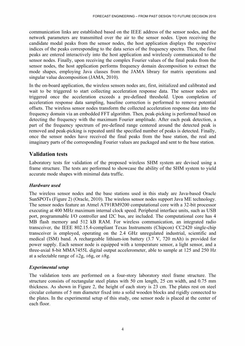
The wireless sensor nodes and the base stations used in this study are Java-based Oracle SunSPOTs (Figure 2) (Oracle, 2010). The wireless sensor nodes support Java ME technology. The sensor nodes feature an Atmel AT91RM9200 computational core with a 32-bit processor executing at 400 MHz maximum internal clock speed. Peripheral interface units, such as USB port, programmable I/O controller and I2C bus, are included. The computational core has 4 MB flash memory and 512 kB RAM. For wireless communication, an integrated radio transceiver, the IEEE 802.15.4-compliant Texas Instruments (Chipcon) CC2420 single-chip transceiver is employed, operating on the 2.4 GHz unregulated industrial, scientific and medical (ISM) band. A rechargeable lithium-ion battery (3.7 V, 720 mAh) is provided for power supply. Each sensor node is equipped with a temperature sensor, a light sensor, and a three-axial 8-bit MMA7455L digital output accelerometer, able to sample at 125 and 250 Hz at a selectable range of ±2g, ±6g, or ±8g. Experimental setup
The validation tests are performed on a four-story laboratory steel frame structure. The structure consists of rectangular steel plates with 50 cm length, 25 cm width, and 0.75 mm thickness. As shown in Figure 2, the height of each story is 23 cm. The plates rest on steel circular columns of 5 mm diameter fixed into a solid wooden blocks and rigidly connected to the plates. In the experimental setup of this study, one sensor node is placed at the center of each floor.
FORECAST ENGINEERING – FROM PAST DESIGN TO FUTURE DECISION 2016
5
Figure 2. Schematic of the laboratory test structure and experimental setup
Description of the validation tests
Upon initialization and calibration of the sensor nodes, the structure is deflected at the fourth floor. The pre-defined acceleration threshold of τ = 0.5 g is exceeded, and acceleration response data is collected by each sensor node. Then, the collected acceleration response data is transformed into the frequency domain via the on-board FFT, and the peak-picking algorithm yields the candidate modal peaks. A total of 10 candidate peaks is chosen in this study. Next, the peaks are sent to the base station and the final peaks are selected and sent back to the sensor nodes. Finally, the sensor nodes send the complex Fourier values corresponding to the selected peaks to the base station, and the mode shapes are extracted through FDD.
To excite as many modes as possible, three groups of tests are performed, with varying excitation direction. More specifically, the structure is excited in the X direction, in the Y direction and in a random direction, while for verification purpose each test is repeated three times. In the first group of tests the structure is deflected in the X direction, in the second group of tests the structure is excited in the Y direction, and in the third group of tests the structure is excited in a random direction. To validate the applicability of the proposed SHM system regardless of the structural state, damage is introduced by loosening the plate-to-column connections of one side of the structure, and the same sets of tests are repeated. The selected peaks and their corresponding frequencies of all tests are shown in Table 1, Table 2, and Table 3.
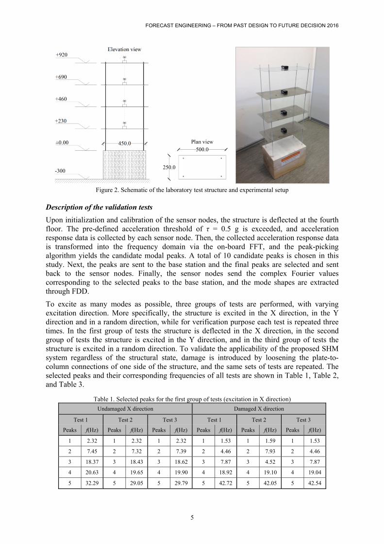
Table 1. Selected peaks for the first group of tests (excitation in X direction)
Undamaged X direction Damaged X direction
Test 1 Test 2 Test 3 Test 1 Test 2 Test 3
Peaks f(Hz) Peaks f(Hz) Peaks f(Hz) Peaks f(Hz) Peaks f(Hz) Peaks f(Hz)
1 2.32 1 2.32 1 2.32 1 1.53 1 1.59 1 1.53
2 7.45 2 7.32 2 7.39 2 4.46 2 7.93 2 4.46
3 18.37 3 18.43 3 18.62 3 7.87 3 4.52 3 7.87
4 20.63 4 19.65 4 19.90 4 18.92 4 19.10 4 19.04
5 32.29 5 29.05 5 29.79 5 42.72 5 42.05 5 42.54
FORECAST ENGINEERING – FROM PAST DESIGN TO FUTURE DECISION 2016
6
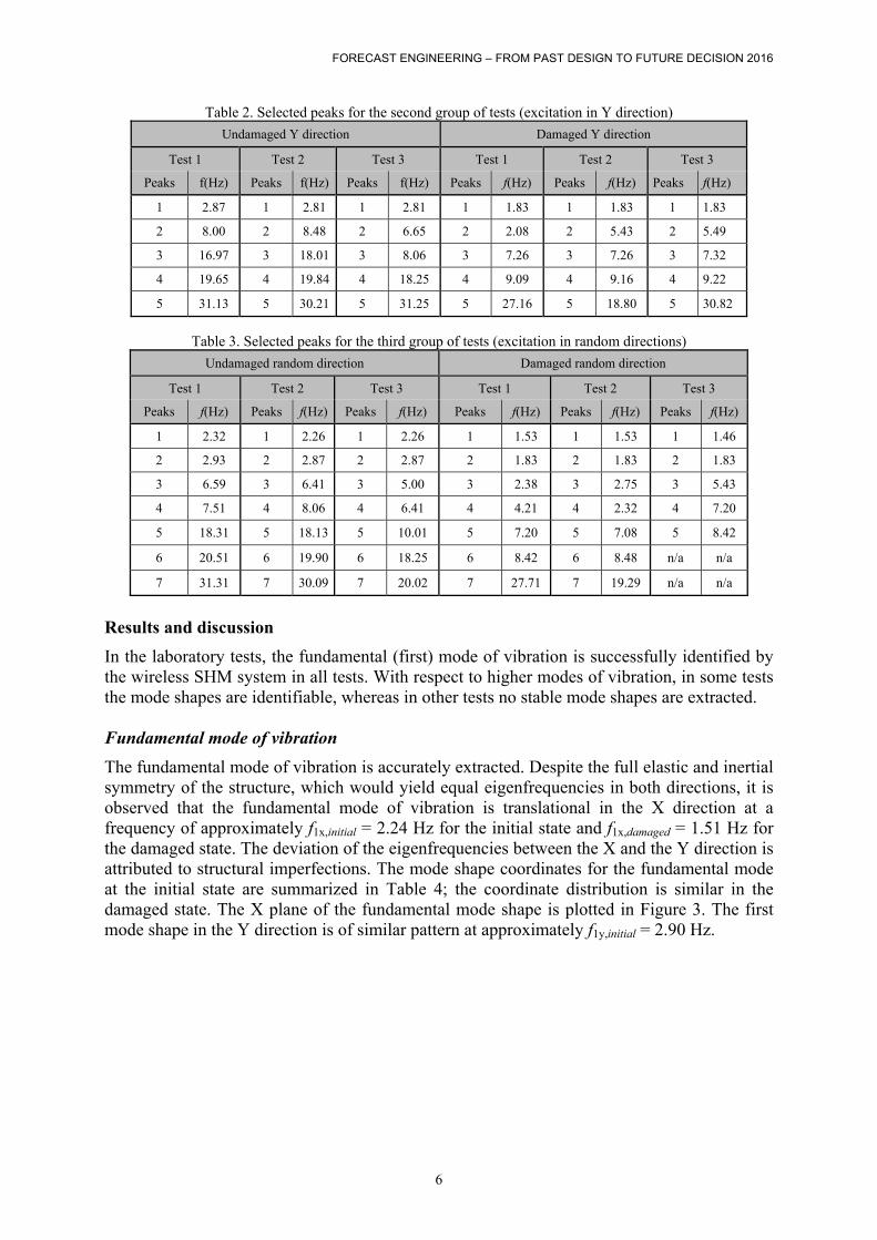
Table 2. Selected peaks for the second group of tests (excitation in Y direction)
Undamaged Y direction Damaged Y direction
Test 1 Test 2 Test 3 Test 1 Test 2 Test 3
Peaks f(Hz) Peaks f(Hz) Peaks f(Hz) Peaks f(Hz) Peaks f(Hz) Peaks f(Hz)
1 2.87 1 2.81 1 2.81 1 1.83 1 1.83 1 1.83
2 8.00 2 8.48 2 6.65 2 2.08 2 5.43 2 5.49
3 16.97 3 18.01 3 8.06 3 7.26 3 7.26 3 7.32
4 19.65 4 19.84 4 18.25 4 9.09 4 9.16 4 9.22
5 31.13 5 30.21 5 31.25 5 27.16 5 18.80 5 30.82
Table 3. Selected peaks for the third group of tests (excitation in random directions)
Undamaged random direction Damaged random direction
Test 1 Test 2 Test 3 Test 1 Test 2 Test 3
Peaks f(Hz) Peaks f(Hz) Peaks f(Hz) Peaks f(Hz) Peaks f(Hz) Peaks f(Hz)
1 2.32 1 2.26 1 2.26 1 1.53 1 1.53 1 1.46
2 2.93 2 2.87 2 2.87 2 1.83 2 1.83 2 1.83
3 6.59 3 6.41 3 5.00 3 2.38 3 2.75 3 5.43
4 7.51 4 8.06 4 6.41 4 4.21 4 2.32 4 7.20
5 18.31 5 18.13 5 10.01 5 7.20 5 7.08 5 8.42
6 20.51 6 19.90 6 18.25 6 8.42 6 8.48 n/a n/a
7 31.31 7 30.09 7 20.02 7 27.71 7 19.29 n/a n/a
Results and discussion
In the laboratory tests, the fundamental (first) mode of vibration is successfully identified by the wireless SHM system in all tests. With respect to higher modes of vibration, in some tests the mode shapes are identifiable, whereas in other tests no stable mode shapes are extracted. Fundamental mode of vibration
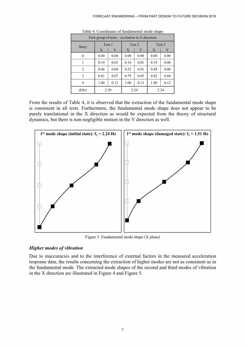
The fundamental mode of vibration is accurately extracted. Despite the full elastic and inertial symmetry of the structure, which would yield equal eigenfrequencies in both directions, it is observed that the fundamental mode of vibration is translational in the X direction at a frequency of approximately f1x,initial = 2.24 Hz for the initial state and f1x,damaged = 1.51 Hz for the damaged state. The deviation of the eigenfrequencies between the X and the Y direction is attributed to structural imperfections. The mode shape coordinates for the fundamental mode at the initial state are summarized in Table 4; the coordinate distribution is similar in the damaged state. The X plane of the fundamental mode shape is plotted in Figure 3. The first mode shape in the Y direction is of similar pattern at approximately f1y,initial = 2.90 Hz.
FORECAST ENGINEERING – FROM PAST DESIGN TO FUTURE DECISION 2016
7
Table 4. Coordinates of fundamental mode shape
First group of tests – excitation in X direction
Story Test 1 Test 2 Test 3
X Y X Y X Y
0 0.00 0.00 0.00 0.00 0.00 0.00
1 0.19 0.03 0.10 0.01 0.19 0.00
2 0.46 0.04 0.52 0.01 0.49 0.00
3 0.81 0.07 0.79 0.05 0.82 0.04
4 1.00 0.12 1.00 0.13 1.00 0.12
f(Hz) 2.30 2.24 2.24
From the results of Table 4, it is observed that the extraction of the fundamental mode shape is consistent in all tests. Furthermore, the fundamental mode shape does not appear to be purely translational in the X direction as would be expected from the theory of structural dynamics, but there is non-negligible motion in the Y direction as well.
Figure 3. Fundamental mode shape (X plane)
Higher modes of vibration
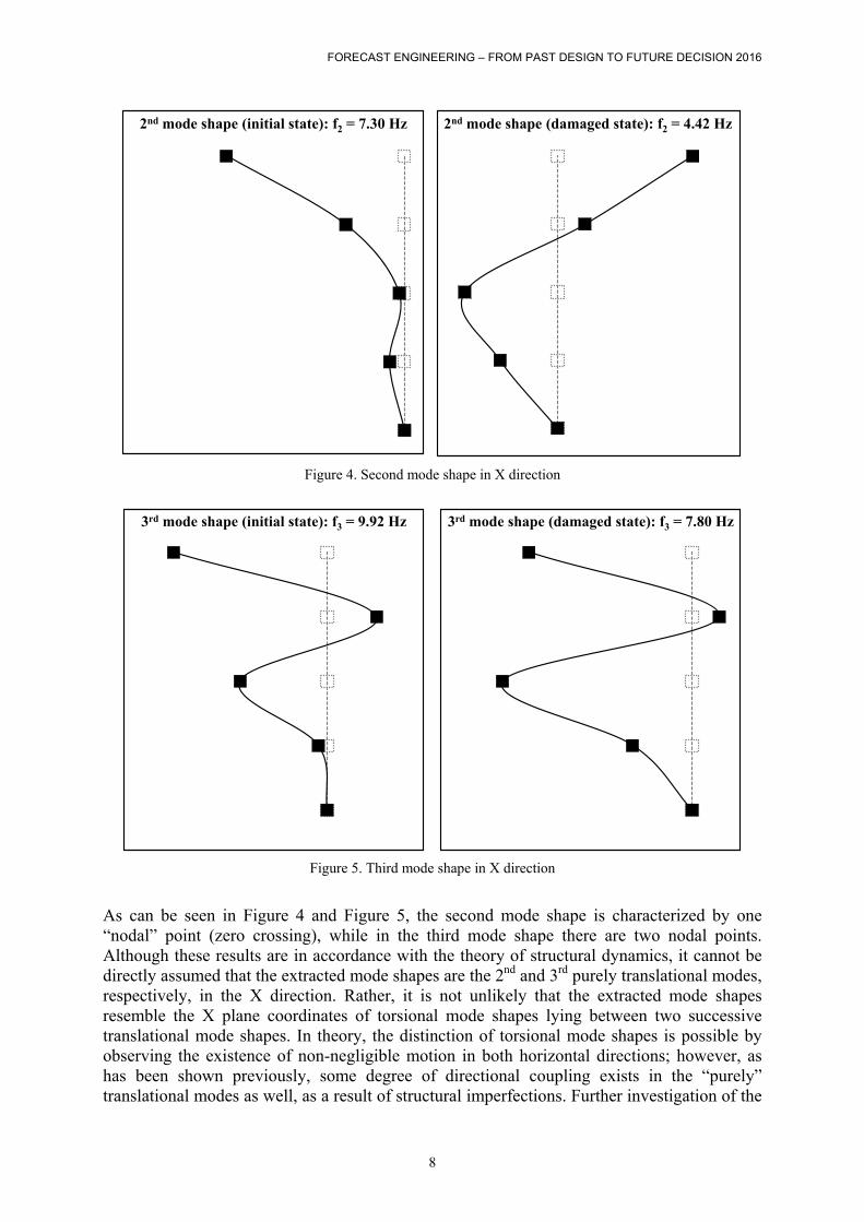
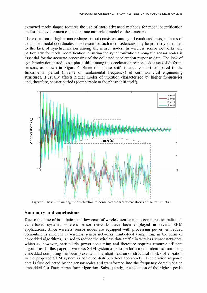
Due to inaccuracies and to the interference of external factors in the measured acceleration response data, the results concerning the extraction of higher modes are not as consistent as in the fundamental mode. The extracted mode shapes of the second and third modes of vibration in the X direction are illustrated in Figure 4 and Figure 5.
1st mode shape (initial state): f1 = 2.24 Hz 1st mode shape (damaged state): f1 = 1.51 Hz
FORECAST ENGINEERING – FROM PAST DESIGN TO FUTURE DECISION 2016
8
Figure 4. Second mode shape in X direction
Figure 5. Third mode shape in X direction
As can be seen in Figure 4 and Figure 5, the second mode shape is characterized by one “nodal” point (zero crossing), while in the third mode shape there are two nodal points. Although these results are in accordance with the theory of structural dynamics, it cannot be directly assumed that the extracted mode shapes are the 2nd and 3rd purely translational modes, respectively, in the X direction. Rather, it is not unlikely that the extracted mode shapes resemble the X plane coordinates of torsional mode shapes lying between two successive translational mode shapes. In theory, the distinction of torsional mode shapes is possible by observing the existence of non-negligible motion in both horizontal directions; however, as has been shown previously, some degree of directional coupling exists in the “purely” translational modes as well, as a result of structural imperfections. Further investigation of the
2nd mode shape (initial state): f2 = 7.30 Hz 2nd mode shape (damaged state): f2 = 4.42 Hz
3rd mode shape (initial state): f3 = 9.92 Hz 3rd mode shape (damaged state): f3 = 7.80 Hz
FORECAST ENGINEERING – FROM PAST DESIGN TO FUTURE DECISION 2016
9
extracted mode shapes requires the use of more advanced methods for modal identification and/or the development of an elaborate numerical model of the structure.
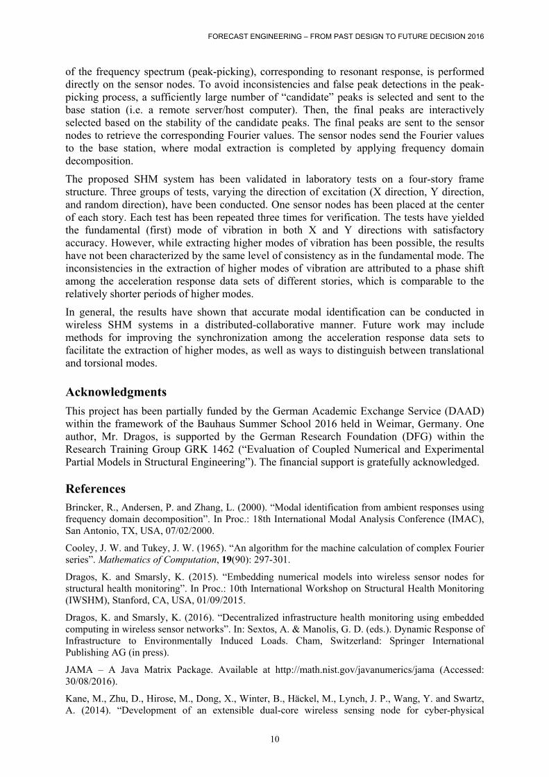
The extraction of higher mode shapes is not consistent among all conducted tests, in terms of calculated modal coordinates. The reason for such inconsistencies may be primarily attributed to the lack of synchronization among the sensor nodes. In wireless sensor networks and particularly for modal identification, ensuring the synchronization among the sensor nodes is essential for the accurate processing of the collected acceleration response data. The lack of synchronization introduces a phase shift among the acceleration response data sets of different sensors, as shown in Figure 6. Since this phase shift is usually short compared to the fundamental period (inverse of fundamental frequency) of common civil engineering structures, it usually affects higher modes of vibration characterized by higher frequencies and, therefore, shorter periods (comparable to the phase shift itself).
Figure 6. Phase shift among the acceleration response data from different stories of the test structure
Summary and conclusions
Due to the ease of installation and low costs of wireless sensor nodes compared to traditional cable-based systems, wireless sensor networks have been employed in several SHM applications. Since wireless sensor nodes are equipped with processing power, embedded computing is inherent to wireless sensor networks. Embedded computing, in the form of embedded algorithms, is used to reduce the wireless data traffic in wireless sensor networks, which is, however, particularly power-consuming and therefore requires resource-efficient algorithms. In this paper, a wireless SHM system able to perform modal identification using embedded computing has been presented. The identification of structural modes of vibration in the proposed SHM system is achieved distributed-collaboratively. Acceleration response data is first collected by the sensor nodes and transformed into the frequency domain via an embedded fast Fourier transform algorithm. Subsequently, the selection of the highest peaks
Figure 6. Phase shift among the acceleration response data from different stories of the test structure
FORECAST ENGINEERING – FROM PAST DESIGN TO FUTURE DECISION 2016
10
of the frequency spectrum (peak-picking), corresponding to resonant response, is performed directly on the sensor nodes. To avoid inconsistencies and false peak detections in the peak-picking process, a sufficiently large number of “candidate” peaks is selected and sent to the base station (i.e. a remote server/host computer). Then, the final peaks are interactively selected based on the stability of the candidate peaks. The final peaks are sent to the sensor nodes to retrieve the corresponding Fourier values. The sensor nodes send the Fourier values to the base station, where modal extraction is completed by applying frequency domain decomposition.
The proposed SHM system has been validated in laboratory tests on a four-story frame structure. Three groups of tests, varying the direction of excitation (X direction, Y direction, and random direction), have been conducted. One sensor nodes has been placed at the center of each story. Each test has been repeated three times for verification. The tests have yielded the fundamental (first) mode of vibration in both X and Y directions with satisfactory accuracy. However, while extracting higher modes of vibration has been possible, the results have not been characterized by the same level of consistency as in the fundamental mode. The inconsistencies in the extraction of higher modes of vibration are attributed to a phase shift among the acceleration response data sets of different stories, which is comparable to the relatively shorter periods of higher modes.
In general, the results have shown that accurate modal identification can be conducted in wireless SHM systems in a distributed-collaborative manner. Future work may include methods for improving the synchronization among the acceleration response data sets to facilitate the extraction of higher modes, as well as ways to distinguish between translational and torsional modes. Acknowledgments
This project has been partially funded by the German Academic Exchange Service (DAAD) within the framework of the Bauhaus Summer School 2016 held in Weimar, Germany. One author, Mr. Dragos, is supported by the German Research Foundation (DFG) within the Research Training Group GRK 1462 (“Evaluation of Coupled Numerical and Experimental Partial Models in Structural Engineering”). The financial support is gratefully acknowledged. References Brincker, R., Andersen, P. and Zhang, L. (2000). “Modal identification from ambient responses using frequency domain decomposition”. In Proc.: 18th International Modal Analysis Conference (IMAC), San Antonio, TX, USA, 07/02/2000.
Cooley, J. W. and Tukey, J. W. (1965). “An algorithm for the machine calculation of complex Fourier series”. Mathematics of Computation, 19(90): 297-301.
Dragos, K. and Smarsly, K. (2015). “Embedding numerical models into wireless sensor nodes for structural health monitoring”. In Proc.: 10th International Workshop on Structural Health Monitoring (IWSHM), Stanford, CA, USA, 01/09/2015.
Dragos, K. and Smarsly, K. (2016). “Decentralized infrastructure health monitoring using embedded computing in wireless sensor networks”. In: Sextos, A. & Manolis, G. D. (eds.). Dynamic Response of Infrastructure to Environmentally Induced Loads. Cham, Switzerland: Springer International Publishing AG (in press).
JAMA – A Java Matrix Package. Available at http://math.nist.gov/javanumerics/jama (Accessed: 30/08/2016).
Kane, M., Zhu, D., Hirose, M., Dong, X., Winter, B., Häckel, M., Lynch, J. P., Wang, Y. and Swartz, A. (2014). “Development of an extensible dual-core wireless sensing node for cyber-physical

FORECAST ENGINEERING – FROM PAST DESIGN TO FUTURE DECISION 2016
11
systems”. In Proc.: SPIE, Sensors and Smart Structures Technologies for Civil, Mechanical, and Aerospace Systems, San Diego, CA, USA, 09/03/2014.
Lei, Y., Shen, W. A., Song, Y. and Wang, Y. (2010). “Intelligent wireless sensors with application to the identification of structural modal parameters and steel cable forces: from the lab to the field”. Advances in Civil Engineering 2010: 1-10.
Oracle Corp. (2010). Sun SPOT eDEMO Technical Datasheet, 8th edition. Sun Labs, Santa Clara, CA, USA.
Semperlotti, F. (2009). “Structural Damage Detection Via Nonlinear System Identification and Structural Intensity Methods”. Ph. D. Dissertation, The Pennsylvania State University, USA.
Wang, Y., Schwartz, A., Lynch, J. P., Law, K. H., Lu, K. C. and Loh, C. H. (2006). “Wireless feedback structural control with embedded computing”. In Proc.: SPIE 11th International Symposium on Nondestructive Evaluation for Health Monitoring and Diagnostics, San Diego, CA, USA, 26/02/2006.
Zimmerman, A., Shiraishi, M., Schwartz, A. and Lynch, J. P. (2008). “Automated modal parameter estimation by parallel processing within wireless monitoring systems”. ASCE Journal of Infrastructure Systems, 14(1): 102-113.