Embed Size (px)
Citation preview
1
A Distributed Three-hop Routing Protocol toIncrease the Capacity of Hybrid Wireless
NetworksHaiying Shen*, Senior Member, IEEE , Ze Li and Chenxi Qiu
Abstract—Hybrid wireless networks combining the advantages of both mobile ad-hoc networks and infrastructure wireless networkshave been receiving increased attention due to their ultra-high performance. An efficient data routing protocol is important in suchnetworks for high network capacity and scalability. However, most routing protocols for these networks simply combine the ad-hoctransmission mode with the cellular transmission mode, which inherits the drawbacks of ad-hoc transmission. This paper presents aDistributed Three-hop Routing protocol (DTR) for hybrid wireless networks. To take full advantage of the widespread base stations,DTR divides a message data stream into segments and transmits the segments in a distributed manner. It makes full spatial reuse ofa system via its high speed ad-hoc interface and alleviates mobile gateway congestion via its cellular interface. Furthermore, sendingsegments to a number of base stations simultaneously increases throughput and makes full use of widespread base stations. Inaddition, DTR significantly reduces overhead due to short path lengths and the elimination of route discovery and maintenance. DTRalso has a congestion control algorithm to avoid overloading base stations. Theoretical analysis and simulation results show thesuperiority of DTR in comparison with other routing protocols in terms of throughput capacity, scalability and mobility resilience. Theresults also show the effectiveness of the congestion control algorithm in balancing the load between base stations.
Index Terms—Hybrid wireless networks, Routing algorithm, Load balancing, Congestion control
F
1 INTRODUCTIONOver the past few years, wireless networks includinginfrastructure wireless networks and mobile ad-hoc net-works (MANETs) have attracted significant research in-terest. The growing desire to increase wireless networkcapacity for high performance applications has stimulat-ed the development of hybrid wireless networks [1–6].A hybrid wireless network consists of both an infras-tructure wireless network and a mobile ad-hoc network.Wireless devices such as smart-phones, tablets and lap-tops, have both an infrastructure interface and an ad-hoc interface. As the number of such devices has beenincreasing sharply in recent years, a hybrid transmissionstructure will be widely used in the near future. Such astructure synergistically combines the inherent advan-tages and overcome the disadvantages of the infrastruc-ture wireless networks and mobile ad-hoc networks.
In a mobile ad-hoc network, with the absence of acentral control infrastructure, data is routed to its des-tination through the intermediate nodes in a multi-hopmanner. The multi-hop routing needs on-demand routediscovery or route maintenance [7–10]. Since the mes-sages are transmitted in wireless channels and throughdynamic routing paths, mobile ad-hoc networks are notas reliable as infrastructure wireless networks. Further-more, because of the multi-hop transmission feature,mobile ad-hoc networks are only suitable for local areadata transmission.
The infrastructure wireless network (e.g. cellular net-work) is the major means of wireless communication inour daily lives. It excels at inter-cell communication (i.e.,communication between nodes in different cells) andInternet access. It makes possible the support of uni-versal network connectivity and ubiquitous computing
• * Corresponding Author. Email: [email protected]; Phone: (864) 6565931; Fax: (864) 656 5910.
• The authors are with the Department of Electrical and Computer Engi-neering, Clemson University, Clemson, SC, 29634.E-mail: {shenh, zel, chenxiq}@clemson.edu
by integrating all kinds of wireless devices into the net-work. In an infrastructure network, nodes communicatewith each other through base stations (BSes). Becauseof the long distance one-hop transmission between BSesand mobile nodes, the infrastructure wireless networkscan provide higher message transmission reliability andchannel access efficiency, but suffer from higher powerconsumption on mobile nodes and the single point offailure problem [11].
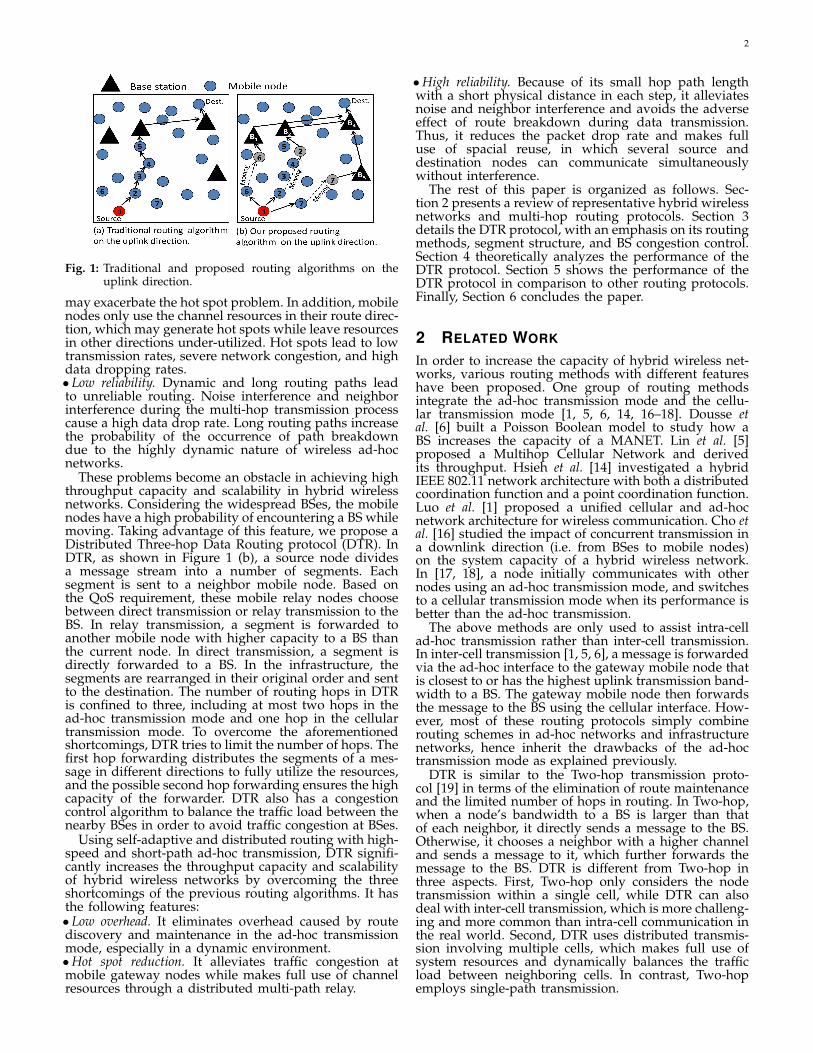
A hybrid wireless network synergistically combinesan infrastructure wireless network and a mobile ad-hoc network to leverage their advantages and overcometheir shortcomings, and finally increases the throughputcapacity of a wide-area wireless network. A routingprotocol is a critical component that affects the through-put capacity of a wireless network in data transmis-sion. Most current routing protocols in hybrid wirelessnetworks [1, 5, 6, 12–18] simply combine the cellulartransmission mode (i.e. BS transmission mode) in infras-tructure wireless networks and the ad-hoc transmissionmode in mobile ad-hoc networks [8, 9, 7]. That is, asshown in Figure 1 (a), the protocols use the multi-hoprouting to forward a message to the mobile gatewaynodes that are closest to the BSes or have the highestbandwidth to the BSes. The bandwidth of a channelis the maximum throughput (i.e., transmission rate inbits/s) that can be achieved. The mobile gateway nodesthen forward the messages to the BSes, functioning asbridges to connect the ad-hoc network and the infras-tructure network.
However, direct combination of the two transmissionmodes inherits the following problems that are rootedin the ad-hoc transmission mode.•High overhead. Route discovery and maintenance incurhigh overhead. The wireless random access mediumaccess control (MAC) required in mobile ad-hoc net-works, which utilizes control handshaking and a back-off mechanism, further increases overhead.•Hot spots. The mobile gateway nodes can easily becomehot spots. The RTS-CTS random access, in which mosttraffic goes through the same gateway, and the floodingemployed in mobile ad-hoc routing to discover routes
2
Fig. 1: Traditional and proposed routing algorithms on theuplink direction.
may exacerbate the hot spot problem. In addition, mobilenodes only use the channel resources in their route direc-tion, which may generate hot spots while leave resourcesin other directions under-utilized. Hot spots lead to lowtransmission rates, severe network congestion, and highdata dropping rates.• Low reliability. Dynamic and long routing paths leadto unreliable routing. Noise interference and neighborinterference during the multi-hop transmission processcause a high data drop rate. Long routing paths increasethe probability of the occurrence of path breakdowndue to the highly dynamic nature of wireless ad-hocnetworks.
These problems become an obstacle in achieving highthroughput capacity and scalability in hybrid wirelessnetworks. Considering the widespread BSes, the mobilenodes have a high probability of encountering a BS whilemoving. Taking advantage of this feature, we propose aDistributed Three-hop Data Routing protocol (DTR). InDTR, as shown in Figure 1 (b), a source node dividesa message stream into a number of segments. Eachsegment is sent to a neighbor mobile node. Based onthe QoS requirement, these mobile relay nodes choosebetween direct transmission or relay transmission to theBS. In relay transmission, a segment is forwarded toanother mobile node with higher capacity to a BS thanthe current node. In direct transmission, a segment isdirectly forwarded to a BS. In the infrastructure, thesegments are rearranged in their original order and sentto the destination. The number of routing hops in DTRis confined to three, including at most two hops in thead-hoc transmission mode and one hop in the cellulartransmission mode. To overcome the aforementionedshortcomings, DTR tries to limit the number of hops. Thefirst hop forwarding distributes the segments of a mes-sage in different directions to fully utilize the resources,and the possible second hop forwarding ensures the highcapacity of the forwarder. DTR also has a congestioncontrol algorithm to balance the traffic load between thenearby BSes in order to avoid traffic congestion at BSes.
Using self-adaptive and distributed routing with high-speed and short-path ad-hoc transmission, DTR signifi-cantly increases the throughput capacity and scalabilityof hybrid wireless networks by overcoming the threeshortcomings of the previous routing algorithms. It hasthe following features:• Low overhead. It eliminates overhead caused by routediscovery and maintenance in the ad-hoc transmissionmode, especially in a dynamic environment.•Hot spot reduction. It alleviates traffic congestion atmobile gateway nodes while makes full use of channelresources through a distributed multi-path relay.
•High reliability. Because of its small hop path lengthwith a short physical distance in each step, it alleviatesnoise and neighbor interference and avoids the adverseeffect of route breakdown during data transmission.Thus, it reduces the packet drop rate and makes fulluse of spacial reuse, in which several source anddestination nodes can communicate simultaneouslywithout interference.
The rest of this paper is organized as follows. Sec-tion 2 presents a review of representative hybrid wirelessnetworks and multi-hop routing protocols. Section 3details the DTR protocol, with an emphasis on its routingmethods, segment structure, and BS congestion control.Section 4 theoretically analyzes the performance of theDTR protocol. Section 5 shows the performance of theDTR protocol in comparison to other routing protocols.Finally, Section 6 concludes the paper.
2 RELATED WORK
In order to increase the capacity of hybrid wireless net-works, various routing methods with different featureshave been proposed. One group of routing methodsintegrate the ad-hoc transmission mode and the cellu-lar transmission mode [1, 5, 6, 14, 16–18]. Dousse etal. [6] built a Poisson Boolean model to study how aBS increases the capacity of a MANET. Lin et al. [5]proposed a Multihop Cellular Network and derivedits throughput. Hsieh et al. [14] investigated a hybridIEEE 802.11 network architecture with both a distributedcoordination function and a point coordination function.Luo et al. [1] proposed a unified cellular and ad-hocnetwork architecture for wireless communication. Cho etal. [16] studied the impact of concurrent transmission ina downlink direction (i.e. from BSes to mobile nodes)on the system capacity of a hybrid wireless network.In [17, 18], a node initially communicates with othernodes using an ad-hoc transmission mode, and switchesto a cellular transmission mode when its performance isbetter than the ad-hoc transmission.
The above methods are only used to assist intra-cellad-hoc transmission rather than inter-cell transmission.In inter-cell transmission [1, 5, 6], a message is forwardedvia the ad-hoc interface to the gateway mobile node thatis closest to or has the highest uplink transmission band-width to a BS. The gateway mobile node then forwardsthe message to the BS using the cellular interface. How-ever, most of these routing protocols simply combinerouting schemes in ad-hoc networks and infrastructurenetworks, hence inherit the drawbacks of the ad-hoctransmission mode as explained previously.
DTR is similar to the Two-hop transmission proto-col [19] in terms of the elimination of route maintenanceand the limited number of hops in routing. In Two-hop,when a node’s bandwidth to a BS is larger than thatof each neighbor, it directly sends a message to the BS.Otherwise, it chooses a neighbor with a higher channeland sends a message to it, which further forwards themessage to the BS. DTR is different from Two-hop inthree aspects. First, Two-hop only considers the nodetransmission within a single cell, while DTR can alsodeal with inter-cell transmission, which is more challeng-ing and more common than intra-cell communication inthe real world. Second, DTR uses distributed transmis-sion involving multiple cells, which makes full use ofsystem resources and dynamically balances the trafficload between neighboring cells. In contrast, Two-hopemploys single-path transmission.
3
Fig. 2: Data transmission in the DTR protocol.
There are other methods proposed to improve routingperformance in hybrid wireless networks. Wu et al. [3]proposed using ad-hoc relay stations to dynamicallyrelay traffic from one cell to another in order to avoidtraffic congestion in BSes. Li et al. [20] surveyed a num-ber of multi-hop cellular network (MCN) architecturesin literature, and compared and discussed methods toreduce the cost of deployment for MCNs. The workin [21] investigates how to allocate the bandwidth tousers to improve the performance of hybrid wirelessnetworks. Thulasiraman et al. [22] further consideredthe wireless interference in optimizing the resource al-location in hybrid wireless networks. The work in [23]proposes a coalitional game theory based cooperativepacket delivery scheme in hybrid wireless networks.
There are also some works [24–26] that study radiofrequency allocation for direction transmission and relaytransmission in hybrid wireless networks. These worksare orthogonal to our study in this paper and can be in-corporated into DTR to further enhance its performance.
The throughput capacity of the hybrid wireless net-work under different settings has also been an activeresearch topic in the hybrid wireless network. The worksin [17, 27] have studied the throughput of hybrid net-work with n nodes and m stations. Liu et al. [28] theoret-ically studied the capacity of hybrid wireless networksunder an one-dimensional network topology and a two-dimensional strip topology. Wang et al. [29] studiedthe multicast throughput of hybrid wireless networksand designed an optimal multicast strategy based ondeduced throughput.
3 DISTRIBUTED THREE-HOP ROUTING PRO-TOCOL3.1 Assumption and OverviewSince BSes are connected with a wired backbone, we as-sume that there are no bandwidth and power constraintson transmissions between BSes. We use intermediate n-odes to denote relay nodes that function as gatewaysconnecting an infrastructure wireless network and amobile ad-hoc network. We assume every mobile node isdual-mode; that is, it has ad-hoc network interface suchas a WLAN radio interface and infrastructure networkinterface such as a 3G cellular interface.
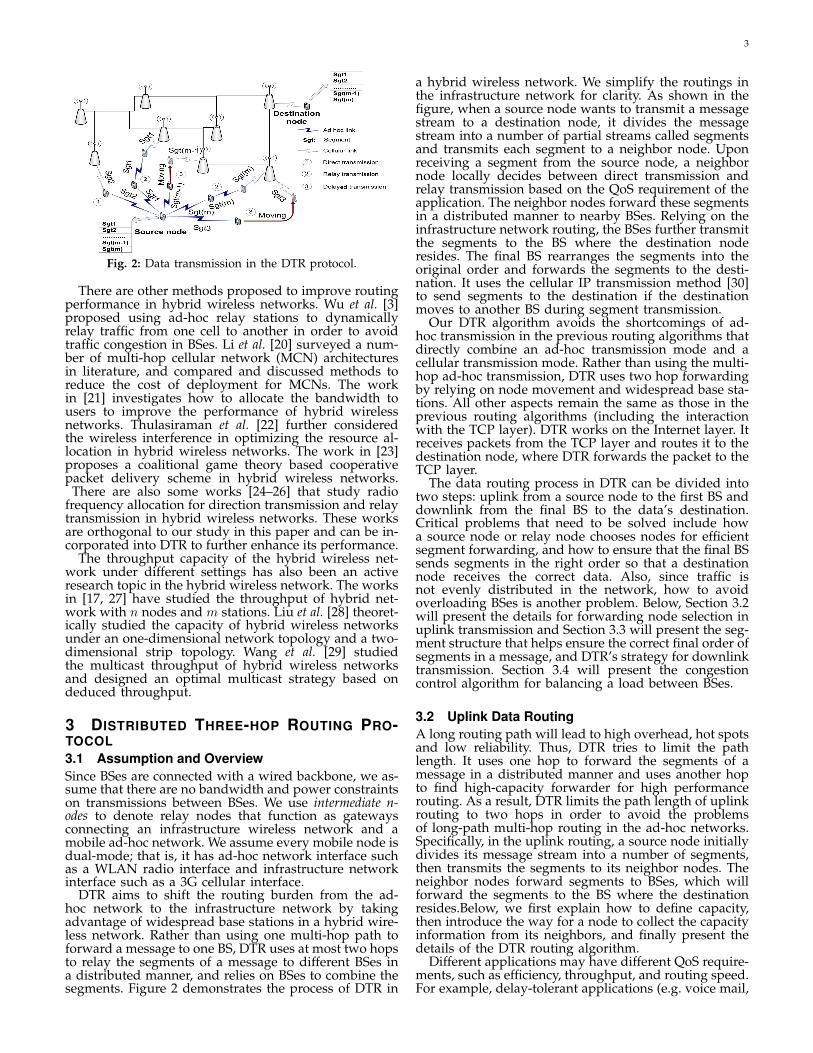
DTR aims to shift the routing burden from the ad-hoc network to the infrastructure network by takingadvantage of widespread base stations in a hybrid wire-less network. Rather than using one multi-hop path toforward a message to one BS, DTR uses at most two hopsto relay the segments of a message to different BSes ina distributed manner, and relies on BSes to combine thesegments. Figure 2 demonstrates the process of DTR in
a hybrid wireless network. We simplify the routings inthe infrastructure network for clarity. As shown in thefigure, when a source node wants to transmit a messagestream to a destination node, it divides the messagestream into a number of partial streams called segmentsand transmits each segment to a neighbor node. Uponreceiving a segment from the source node, a neighbornode locally decides between direct transmission andrelay transmission based on the QoS requirement of theapplication. The neighbor nodes forward these segmentsin a distributed manner to nearby BSes. Relying on theinfrastructure network routing, the BSes further transmitthe segments to the BS where the destination noderesides. The final BS rearranges the segments into theoriginal order and forwards the segments to the desti-nation. It uses the cellular IP transmission method [30]to send segments to the destination if the destinationmoves to another BS during segment transmission.
Our DTR algorithm avoids the shortcomings of ad-hoc transmission in the previous routing algorithms thatdirectly combine an ad-hoc transmission mode and acellular transmission mode. Rather than using the multi-hop ad-hoc transmission, DTR uses two hop forwardingby relying on node movement and widespread base sta-tions. All other aspects remain the same as those in theprevious routing algorithms (including the interactionwith the TCP layer). DTR works on the Internet layer. Itreceives packets from the TCP layer and routes it to thedestination node, where DTR forwards the packet to theTCP layer.
The data routing process in DTR can be divided intotwo steps: uplink from a source node to the first BS anddownlink from the final BS to the data’s destination.Critical problems that need to be solved include howa source node or relay node chooses nodes for efficientsegment forwarding, and how to ensure that the final BSsends segments in the right order so that a destinationnode receives the correct data. Also, since traffic isnot evenly distributed in the network, how to avoidoverloading BSes is another problem. Below, Section 3.2will present the details for forwarding node selection inuplink transmission and Section 3.3 will present the seg-ment structure that helps ensure the correct final order ofsegments in a message, and DTR’s strategy for downlinktransmission. Section 3.4 will present the congestioncontrol algorithm for balancing a load between BSes.
3.2 Uplink Data RoutingA long routing path will lead to high overhead, hot spotsand low reliability. Thus, DTR tries to limit the pathlength. It uses one hop to forward the segments of amessage in a distributed manner and uses another hopto find high-capacity forwarder for high performancerouting. As a result, DTR limits the path length of uplinkrouting to two hops in order to avoid the problemsof long-path multi-hop routing in the ad-hoc networks.Specifically, in the uplink routing, a source node initiallydivides its message stream into a number of segments,then transmits the segments to its neighbor nodes. Theneighbor nodes forward segments to BSes, which willforward the segments to the BS where the destinationresides.Below, we first explain how to define capacity,then introduce the way for a node to collect the capacityinformation from its neighbors, and finally present thedetails of the DTR routing algorithm.
Different applications may have different QoS require-ments, such as efficiency, throughput, and routing speed.For example, delay-tolerant applications (e.g. voice mail,
4
e-mail and text messaging) do not necessarily need fastreal-time transmission and may make throughput thehighest consideration to ensure successful data trans-mission. Some applications may take high mobility astheir priority to avoid hot spots and blank spots. Hotspots are areas where BS channels are congested, whileblank spots are areas without signals or with very weaksignals. High-mobility nodes can quickly move out of ahot spot or blank spot and enter a cell with high band-width to a BS, thus providing efficient data transmission.Throughput can be measured by bandwidth, mobilitycan be measured by the speed of node movement, androuting speed can be measured by the speed of dataforwarding. Bandwidth can be estimated using the non-intrusive technique proposed in [31]. In this work, wetake throughput and routing speed as examples forthe QoS requirement. We use a bandwidth/queue metricto reflect node capacity in throughput and fast dataforwarding. The metric is the ratio of a node’s channelbandwidth to its message queue size. A larger band-width/queue value means higher throughput and messageforwarding speed, and vice versa.
When choosing neighbors for data forwarding, a nodeneeds the capacity information (i.e., queue size andbandwidth) of its neighbors. Also, a selected neighborshould have enough storage space for a segment. Tokeep track of the capacity and storage space of its neigh-bors, each node periodically exchanges its current capac-ity and storage information with its neighbors. In the ad-hoc network component, every node needs to periodical-ly send “hello” messages to identify its neighbors. Tak-ing advantage of this policy, nodes piggyback the capac-ity and storage information onto the “hello” messages inorder to reduce the overhead caused by the informationexchanges. If a node’s capacity and storage space arechanged after its last “hello” message sending when itreceives a segment, it sends its current capacity and stor-age information to the segment forwarder. Then, the seg-ment forwarder will choose the highest capacity nodesin its neighbors based on the most updated information.
When a source node sends out message segments,it chooses the neighbors that have enough space forstoring a segment, and then chooses neighbors that havethe highest capacity. In order to find higher capacityforwarders in a larger neighborhood around the source,each segment receiver further forwards its received seg-ment to its neighbor with the highest capacity. Thatis, after a neighbor node mi receives a segment fromthe source, it uses either direct transmission or relaytransmission. If the capacity of each of its neighbors isno greater than itself, relay node mi uses direct trans-mission. Otherwise, it uses relay transmission. In directtransmission, the relay node sends the segment to a BSif it is in a BS’s region. Otherwise, it stores the segmentwhile moving until it enters a BS’s region. In relaytransmission, relay node mi chooses its highest-capacityneighbor as the second relay node based on the QoSrequirement. The second relay node will use direct trans-mission to forward the segment directly to a BS. As a re-sult, the number of transmission hops in the ad-hoc net-work component is confined to no more than two. Thesmall number of hops help to increase the capacity of thenetwork and reduce channel contention in ad-hoc trans-mission. Algorithm 1 shows the pseudo-code for neigh-bor node selection and message forwarding in DTR.
The purpose of the second hop selection is to finda higher capacity node as the message forwarder inorder to improve the performance of the QoS require-
510
A
10
7
44
9
7
BSource
Base station Mobile node
(a) Source node has higher‐capacity neighbors.
(b) Source node has no higher‐capacity neighbors.
3
25
6
4
1
75
3
89
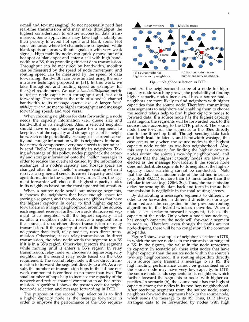
Fig. 3: Neighbor selection in DTR.
ment. As the neighborhood scope of a node for high-capacity node searching grows, the probability of findinghigher capacity nodes increases. Thus, a source node’sneighbors are more likely to find neighbors with highercapacities than the source node. Therefore, transmittingdata segments to neighbors and enabling them to choosethe second relays help to find higher capacity nodes toforward data. If a source node has the highest capacityin its region, the segments will be forwarded back to thesource node according to the DTR protocol. The sourcenode then forwards the segments to the BSes directlydue to the three-hop limit. Though sending data backand forth leads to latency and bandwidth wastage, thiscase occurs only when the source nodes is the highestcapacity node within its two-hop neighborhood. Also,this step is necessary for finding the highest capacitynodes within the source’s two-hop neighborhood, andensures that the highest capacity nodes are always s-elected as the message forwarders. If the source nodedoes not distribute segments to its neighbors, the higher-capacity node searching cannot be conducted. Notethat the data transmission rate of the ad-hoc interface(e.g. IEEE 802.11) is more than 10 times faster than thecellular interface (e.g. GSM, 3G). Thus, the transmissiondelay for sending the data back and forth in the ad-hoctransmission is negligible in the total routing latency.
By distributing a message’s segments to different n-odes to be forwarded in different directions, our algo-rithm reduces the congestion in the previous routingalgorithms in the hybrid wireless networks. When anode selects a relay to forward a segment, it checks thecapacity of the node. Only when a node, say node mi,has enough capacity, the node will forward a segmentto node mi. Therefore, even though the paths are notnode-disjoint, there will be no congestion in the commonsub-paths.
Figure 3 shows examples of neighbor selection in DTR,in which the source node is in the transmission range ofa BS. In the figures, the value in the node representsits capacity. In scenario (a), there exist nodes that havehigher capacity than the source node within the source’stwo-hop neighborhood. If a routing algorithm directlylet a source node transmit a message to its BS, thehigh routing performance cannot be guaranteed sincethe source node may have very low capacity. In DTR,the source node sends segments to its neighbors, whichfurther forward the segments to nodes with higher ca-pacities. In scenario (b), the source node has the highestcapacity among the nodes in its two-hop neighborhood.After receiving segments from the source node, someneighbors forward the segments back to the source node,which sends the message to its BS. Thus, DTR alwaysarranges data to be forwarded by nodes with high
5
capacity to their BSes. DTR achieves higher throughputand faster data forwarding speed by taking into accountnode capacity in data forwarding.
Algorithm 1 Pseudo-code for neighbor node selectionand message forwarding.1: ChooseRelay( ) {2: //choose neighbors with sufficient caches and bandwidth/queue (b/q) rates3: Query storage size and QoS requirement info. from neighbors4: for each neighbor n do5: if n.cache.size>segment.length && n.b/q>this.b/q then6: Add n to R = {r1, . . . rm, ...} in a descending order of b/q7: end if8: end for9: Return R
10: }11: Transmission( ) {12: if it is a source node then13: //routing conducted by a source node14: //choose relay nodes based on QoS requirement15: R=ChooseRelay( );16: Send segments to {r1, . . . rm} in R17: else18: //routing conducted by a neighbor node19: if this.b/q ≤ b/q of all neighbors then20: //direct transmission21: if within the range of a BS then22: Transmit the segment directly to the BS23: end if24: else25: //relay transmission26: nodei=getHighestCapability(ChooseRelay( ))27: Send a segment to nodei28: end if29: end if30: }
Algorithm 2 Pseudo-code for a BS to reorder and for-ward segments to destination nodes.1: //a cache pool is built for each data stream2: //there are n cache pools currently3: if receives a segment (S,D,m,s,q) then4: if there is no cache pool with msg sequence num equals m then5: Create a cache pool n+ 1 for the stream m6: else7: //the last delivered segment of stream m has sequence num i− 18: if s == i then9: Send out segment (S,D,m,s,q) to D
10: i++;11: else12: Add segment (S,D,m,s) into cache pool m13: end if14: end if15: end if
3.3 Downlink Data Routing and Data ReconstructionAs mentioned above, the message stream of a source n-ode is divided into several segments. After a BS receivesa segment, it needs to forward the segment to the BS,where the destination node resides (i.e., the destinationBS). We use the mobile IP protocol [32] to enable BSes toknow the destination BS. In this protocol, each mobilenode is associated with a home BS, which is the BS in thenode’s home network, regardless of its current locationin the network. The home network of a node contains itsregistration information identified by its home address,which is a static IP address assigned by an ISP. Ina hybrid wireless network, each BS periodically emitsbeacon signals to locate the mobile nodes in its range.When a mobile node mi moves away from its home BS,the BS where mi currently resides detects mi and sends
its IP address to the home BS of mi. When a BS wantsto contact mi, it contacts the home BS of mi to find thedestination BS where mi currently resides at.
However, the destination BS recorded in the home BSmay not be the most up-to-date destination BS sincedestination mobile nodes switch between the coverageregions of different BSes during data transmission tothem. For instance, data is transmitted to BS Bi that hasthe data’s destination, but the destination has movedto the range of BS Bj before the data arrives at BSBi. To deal with this problem, we adopt the CellularIP protocol [30] for tracking node locations. With thisprotocol, a BS has a home agent and a foreign agent.The foreign agent keeps track of mobile nodes movinginto the ranges of other BSes. The home agent interceptsin-coming segments, reconstructs the original data, andre-routes it to the foreign agent, which then forwards thedata to the destination mobile node.
After the destination BS receives the segments of amessage, it rearranges the segments into the originalmessage and then sends it to the destination mobilenode. A vital issue is guaranteeing that the segments arecombined in the correct order. For this purpose, DTRspecifies the segment structure format. Each segmentcontains eight fields, including: (1) source node IP ad-dress (denoted by S); (2) destination node IP address(denoted by D); (3) message sequence number (denotedby m); (4) segment sequence number (denoted by s);(5) QoS indication number (denoted by q); (6) data; (7)length of the data; and (8) checksum. Fields (1)-(5) arein the segment head.
The role of the source IP address field is to informthe destination node where the message comes from.The destination IP address field indicates the destinationnode, and is used to locate the final BS. After sendingout a message stream to a destination, a source nodemay send out another message stream to the samedestination node. The message sequence number differenti-ates the different message streams initiated by the samesource node. The segment sequence number is used to findthe correct transmission sequence of the segments fortransmission to a destination node. The data is the actualinformation that a source node wants to transmit to adestination node. The length field specifies the lengthof the DTR segment including the header in bytes. Thechecksum is used by the receiver node to check whetherthe received data has errors. The QoS indication number isused to indicate the QoS requirement of the application.
Thus, each segment’s head includes the informationrepresented by (S,D,m, s, q)(m, s = 1, 2, 3, ...). When asegment with head (S,D,m, s, q) arrives at a BS, the BScontacts D’s home BS to find the destination BS whereD stays via the mobile IP protocol. It then transmits thesegment to the destination BS through the infrastructurenetwork component. After arriving at the BS, the seg-ment waits in the cache for its turn to be transmitted toits destination node based on its message and segmentsequence numbers. At this time, if another segmentcomes with a head labelled (S,D, (m + 1), s, q), whichmeans that it is from the same source node but belongsto another data stream, the BS will put it to anotherstream. If the segment is labeled as (S,D,m, (s+1), q), itmeans that this segment belongs to the same data streamof the same source node as segment (S,D,m, s, q). Thecombination of the source node’s sequence number andsegment sequence number helps to locate the streamand the position of a segment in the steam. In order tointegrate the segments into their correct order to retrievethe original data, the segments in the BS are transmitted
6
to the destination node in the order of the segments’sequence in the original message. If a segment has notarrived at the final BS, its subsequent segments will waitin the final BS until its arrival. Algorithm 2 shows thepseudo-code for a BS to reorder and forward segments totheir destinations. Note that in the cache, we can set thetimer based on the packet rate and storage limit. In otherwords, the timer should be set as large as possible tofully utilize the storage on BSes to ensure that a messagehas a high probability to be recovered.
3.4 Congestion Control in Base StationsCompared to the previous routing algorithms in hybridwireless networks, DTR can distribute traffic load amongmobile nodes more evenly. Though the distributed rout-ing in DTR can distribute traffic load among nearby B-Ses, if the traffic load is not distributed evenly in the net-work, some BSes may become overloaded while other B-Ses remain lightly loaded. We propose a congestion con-trol algorithm to avoid overloading BSes in uplink trans-mission (e.g., B1, B2 and B3 in Figure 1 (b)) and down-link transmission (e.g., B4 in Figure 1 (b)), respectively.
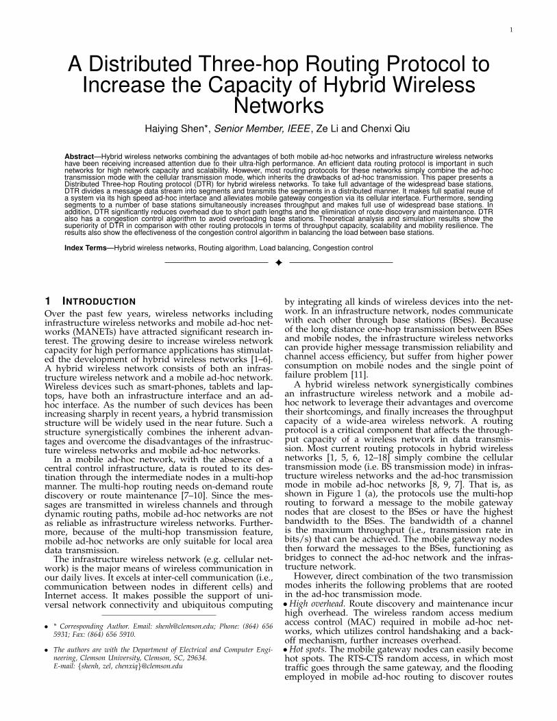
In the hybrid wireless network, BSes send beacon mes-sages to identify nearby mobile nodes. Taking advantageof this beacon strategy, once the workload of a BS, sayBi, exceeds a pre-defined threshold, Bi adds an extrabit in its beacon message to broadcast to all the nodesin its transmission range. Then, nodes near Bi knowthat Bi is overloaded and will not forward segments toBi. When a node near Bi, say mi, needs to forward asegment to a BS, it will send the segment to Bi based onthe DTR algorithm. In our congestion control algorithm,because Bi is overloaded, rather than targeting Bi, miwill forward the segment to a lightly loaded neighboringBS of Bi. To this end, node mi first queries a multi-hoppath to a lightly loaded neighboring BS of Bi. Node mibroadcasts a query message into the system. We set theTTL for the path query forwarding step to a constant(e.g., 3). The query message is forwarded along othernodes until a node (say mj) near a lightly loaded BS(say Bj) is reached. Due to broadcasting, a node mayreceive multiple copies of the same queries. Each nodeonly remembers mi and the node that forwards the firstquery (i.e., its preceding node), and ignores all other thesame queries. In this way, a multi-hop path between thesource node and the lightly loaded base station can beformed. Node mj responds to the path query by addinga reply bit and the address of mi into its beacon messageto its preceding node in the path. This beacon receiveralso adds a reply bit and the address of mi into itsbeacon message to its preceding node in the path. Thisprocess repeats until mi receives the beacon. Thus, eachnode knows its preceding node and succeeding nodein the path from mi and mj based on the address ofmi. Then, mi’s message can be forwarded along theobserved path along the nodes. The observed path canalways be used by mi for any subsequent messages toBj as long as it is not broken. The neighboring BSesof an overloaded BS may also be overloaded. As themobile nodes near an overloaded BS know that the BSis overloaded, when they receive a query message tofind a path to an underloaded BS, they do not forwardthe message towards their overloaded BSes.
Node mi may receive responses from a few nodesnear BSes. It can choose b (b ≥ 1) neighboring BSes ofthe destination to forward the segment. The redundanttransmissions enhance the data transmission reliabilitywhile also increase the routing overhead. Thus, the value
of b should be carefully determined based on the avail-able resources for routing and the reliability demand. Ifb is set to a large value, the routing reliability is high atthe cost of high overhead. If b is set to a small value, therouting reliability is low while the overhead is reduced.After the neighboring BSes receive the segments, theyfurther forward the segments to the destination BS,which forwards the segments to the destination node.In this way, the heavy traffic from mobile nodes to a BScan be distributed among neighboring BSes quickly.
Next, we discuss how to handle the case when thedestination BS is congested. If a BS has not receivedconfirmation from the destination BS during a certaintime period after it sends out a segment, it assumesthat the destination BS is overloaded. Then, it sendsthe segment to b (b ≥ 1) lightly loaded neighboringBSes of the destination BS from its routing table. If anattempted neighboring BS does not respond during acertain time period, it is also considered as overloaded.Then, the BS keeps trying other neighboring BSes untilfinding lightly loaded BSes. Redundant neighboringBSes are selected in order to increase routing reliability.The constant b should be set to an appropriate valueconsidering factors such as the network size and theamount of traffic in order to achieve an optimal trade-offbetween overhead and reliability.
After receiving the message, each lightly loaded neigh-boring BS of the destination BS finds a multi-hop pathto the destination mobile node. It broadcasts a pathquery message, which includes the IDs of the destinationBS and the destination node, to the mobile nodes inits region. The path querying process is similar to theprevious path querying for a lightly loaded BS. Thenodes further forward the path query to their neighborsuntil the query reaches the destination node. Here, wedo not piggyback the query to beacon messages becausethis querying is for a specific mobile node rather thanany mobile node near a lightly loaded BS. Including themobile node’s ID into beacon messages generates veryhigh overhead.
B1
B2
B3
B4
Mobile nodeSource node
Destination node
B5 B6
s
D
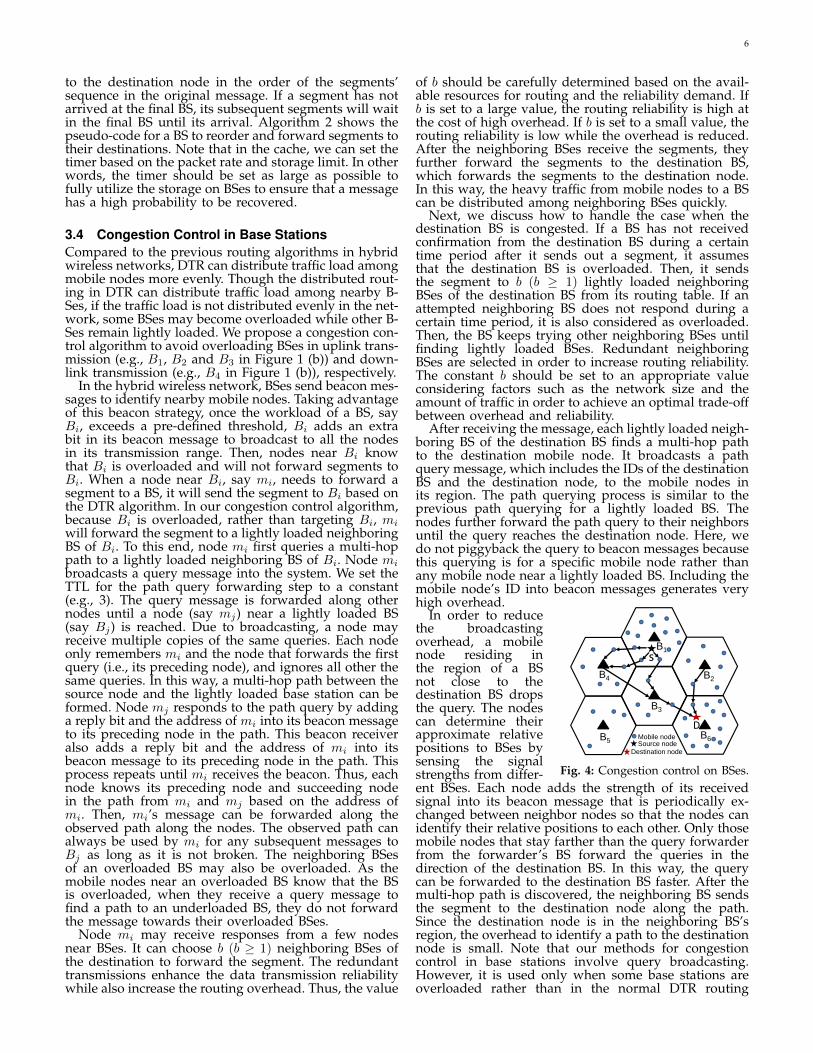
Fig. 4: Congestion control on BSes.
In order to reducethe broadcastingoverhead, a mobilenode residing inthe region of a BSnot close to thedestination BS dropsthe query. The nodescan determine theirapproximate relativepositions to BSes bysensing the signalstrengths from differ-ent BSes. Each node adds the strength of its receivedsignal into its beacon message that is periodically ex-changed between neighbor nodes so that the nodes canidentify their relative positions to each other. Only thosemobile nodes that stay farther than the query forwarderfrom the forwarder’s BS forward the queries in thedirection of the destination BS. In this way, the querycan be forwarded to the destination BS faster. After themulti-hop path is discovered, the neighboring BS sendsthe segment to the destination node along the path.Since the destination node is in the neighboring BS’sregion, the overhead to identify a path to the destinationnode is small. Note that our methods for congestioncontrol in base stations involve query broadcasting.However, it is used only when some base stations areoverloaded rather than in the normal DTR routing
7
algorithm in order to avoid load congestion in BSes.Figure 4 shows an example of the congestion control
on BSes when b = 2. As shown in figure, BS B1 iscongested. Then, the relay nodes of the source node’smessage broadcast locally by beacon piggybacking tofind multi-hop paths which lead to B3 and B4. Therelay nodes then send segments along the paths. In thisway, the traffic originally targeting overloaded B1 canbe spread out to the neighboring BSes B3 and B4. B3and B4 further forward the segments to the destinationBS B6 if B6 is not congested. If B6 is also congested,B3 and B4 send the segments to the neighboring BSesof B6. Specifically, B4 sends the segment to B3. B3 doesnot forward the segment to another BS since it alreadyis close to B6. B3 then finds a multi-hop path to the des-tination node and uses ad-hoc transmission to forwardthe segments to the destination node. Similarly, when B2wants to send a segment to the destination node, it alsouses a multi-hop path for the segment transmission.
4 PERFORMANCE ANALYSIS OF THE DTRPROTOCOL
σ Node density M Number of BSesl Segment’s length sh Area size of a cell
n(S) Number of nodes in area S R Transmission rangeWi Bandwidth of a node vi mi Mobile node i
P (σ,M)Throughput n(σ,M) Number of nodes
TABLE 1: Parameter table.
In this section, we analyze the effectiveness of theDTR protocol at enhancing the capacity and scalabilityof hybrid wireless networks. In our analysis, we use thesame scenario in [17] for hybrid wireless networks, anduse the same scenario in [33] for the ad-hoc networkcomponent. We present the scenarios and some conceptsbelow. We consider a large number of mobile nodesuniformly and randomly deployed over a 2-D field.The moving directions of the nodes are independentand identically distributed (i.i.d.). The distribution ofmobile nodes can be modeled as a homogeneous Poissonprocess with node density σ [34]. That is, given an areaof size S in the field, the number of nodes in the area,denoted by n(S), follows the Poisson distribution withthe parameter σS,
Pr (n(S) = k) =(σS)ke−σS
k!, k = 0, 1, 2, ... (1)
Besides mobile nodes, there are M BSes regularly de-ployed in the field. The BSes divide the area into ahexagon tessellation, in which each hexagon has sidelength h. The BSes are assumed to be connected togetherby a wired network. We assume that the link bandwidthsin the wired network are large enough so that thereare no bandwidth constraints between BSes. In single-path transmission, a message is sequentially transmittedin one routing path. In multi-path transmission, a messageis divided into a number of segments that are forwardedalong multiple paths in a distributed manner. We assumeeach segment has the same length l. Table 1 lists thenotations used in our analysis.
We assume that the transmission range of all mobilenodes and all BSes is R (R > h). In this paper, we useprotocol model [17, 33] to describe the interference amongnodes; that is, a transmission from a node (here “node”can be either mobile node or BS) vi to another node vj issuccessful if the following two conditions are satisfied:1) vj is within the transmission range of vi, i.e.,
|vi − vj | ≤ R (2)
where |vi−vj | represents the Euclidean distance betweenvi and vj in the plane.2) For any other node vk that is simultaneously trans-mitting over the same channel,
|vk − vj | ≥ (1 + ∆)|vi − vj |. (3)Formula (3) guarantees a guard zone around the receiv-ing node to prevent a neighboring node from transmit-ting on the same channel at the same time. The radiusof the guard zone is (1 + ∆) times the distance betweenthe sender and the receiver. The parameter ∆ defines thesize of the guard zone and we require that ∆ > 0.
We first adopt a concept called aggregate throughputcapacity introduced in [17, 33] to measure the throughputof the network.
Definition (Aggregate Throughput Capacity of HybridNetworks) The aggregate throughput capacity of a hy-brid wireless network is of order Θ(f(σ,M)) if there aredeterministic constants α > 0, and α′ < +∞ such that
limM→∞
Pr (P (σ,M) = αf(σ,M) is feasible) = 1 (4)
lim infM→∞
Pr(P (σ,M) = α′f(σ,M) is feasible
)< 1. (5)
Since the working frequency of infrastructure net-works is around 700MHz while that of ad-hoc networksis 2.4 GHz, the communications in infrastructure mode(between mobile nodes and BSes through cellular inter-face) would not generate interference to ad-hoc mode.We divide the channel for infrastructure mode transmis-sions into uplink and downlink parts, according to thetransmission direction relative to the BSes. Accordingly,in the DTR protocol, the traffic of each S-D pair iscomposed of at most two intra-cell traffics, one uplinktraffic and one download traffic. Since uplink traffic anddownlink traffic use different sub-channels, there is alsono interference between these two types of traffics. Foreach node vi, we denote the bandwidth assigned to intra-cell, uplink, and downlink sub-channels by W int
i , W upi
and W downi , respectively. We let W up
i = W downi because
there are the same amount of uplink traffic and down-link traffic. The transmission rates should sum to Wi,i.e., W int
i +W upi +W down
i = Wi. Though no interferenceexists between intra-cell, uplink, and downlink traffics,interference exists between the same type of traffic in acell and between different cells. Fortunately, there is anefficient spatial transmission schedule that can preventsuch interferences [17]. First, to avoid the interferencein a cell, any two nodes within the cell are not allowedto transmit with the same traffic mode at the same time.Second, to avoid the interference between different cells,the cells are spatially divided into a number of groupsand transmissions in the cells of the same group do notinterfere with each other. If the groups are scheduledto transmit in a round robin fashion, each cell will beable to transmit once every fixed amount of time withoutinterfering with each other.
Below, we show how many groups we need to dividethe cells to prevent interference. We adopt the notionof interfering neighbors introduced in [17], and give thenumber of cells that can be affected by a transmission inone cell. Two cells are defined to be interfering neighborsif there is a point in one cell which is within a distance(2+∆)R of a point in the other cell. Accordingly, if twocells are not interfering neighbors, transmissions in onecell do not interfere with transmissions in the other cell.[17] has proved that (1) each cell has no more than c1interfering neighbors (Lemma 1 in [17]), where c1 is aconstant
c1 =4
3
(3l + 2R+ ∆R
3l
)2
, (6)
8
and (2) all cells should be divided into c1 + 1 groupsand the whole channel should be divided into c1 + 1subchannels, where each subchannel is allocated to thecells in one group. Thus, the number of group we needto divide the cells to prevent interference is c1 + 1.
Before calculating the aggregate throughput capacityof DTR, we first introduce Lemma 4.1.
Lemma 4.1: The number of cells that have mobile n-odes is Θ(M).
Proof: Denote the number of cells having mobilenodes by M1. To prove M1 = Θ(M), we need to provethat there exists deterministic constants α > 0 andα′ < +∞ such that
limM→∞
Pr (M1 = αM) = 1, (7)
lim infM→∞
Pr(M1 = α′M
)< 1. (8)
For Formula (8), let α′ = 2. Because the number of cellshaving mobile nodes is upper bounded by M , then
lim infM→∞
Pr (M1 = 2M is feasible) = 0. (9)Now, we prove that Formula (7) can also be satisfied
for some constant α. Because the number of nodes in acell follows a Poisson distribution and the size of eachcell (hexagon) is sh = 3
√3h2, then we can derive the
probability that no mobile node is in a cell equals
Pr (n(Sh) = 0) =σ0e−sh
0!= e−sh . (10)
Consider an arbitrary cell k, let X1, X2, ..., Xk,..., XMbe i.i.d. random variables, where Xk represents whethercell k has mobile nodes. Then, Xk is defined as follows:
Xk =
{1 cell k has mobile nodes0 cell k does not have mobile nodes (11)
and E(Xk) = e−sh . For simplicity, let c2 = 1 − e−sh .Then, M1 =
∑Mk=1Xk. By the Strong Law of Large Number
(SLLN) [34],Pr
(lim
M→∞
∑Mk=1Xk
M= c2
)= 1, (12)
which implies that limM→∞ Pr (M1 = c2M) = 1, whichindicates that when α = c2, Formula (7) can also besatisfied.
Lemma 4.2: Let n(σ,M) denote the number of mobilenodes in the whole network. Then,
limM→∞
Pr (n(σ,M) = shM) = 1. (13)
Proof: Let Z1, Z2, ..., ZM be i.i.d. random variablesrepresenting the number of nodes in cell 1, 2,..., M ,respectively. Then, n(σ,M) =
∑Mk=1 Zk. Because each
Zk follows a Poisson distribution with parameter sh,E(Zk) = sh, ∀1 ≤ k ≤M . According to SLLN,
Pr
(lim
M→∞
∑Mk=1 Zk
M= sh
)= 1, (14)
which implies that limM→∞ Pr(∑M
k=1 Zk = shM)
= 1,and hence limM→∞ Pr (n(σ,M) = shM) = 1.
Theorem 4.1: For a hybrid network of M BSes and σmobile node density, where each node has the intra-cell,uplink and downlink sub-channel bandwidth satisfying
W downi = W up
i = W up = W/4, W inti = W int = W/2 (15)
the aggregate throughput capacity of DTR isP (σ,M) = Θ(MW ). (16)
Proof: To prove P (σ,M) = Θ(MW ), we need toprove that there exists deterministic constants α > 0 andα′ <∞ such that
limM→∞
Pr{P (σ,M) = αMW is feasible} = 1 (17)lim infM→∞
Pr{P (σ,M) = α′MW is feasible} < 1. (18)Recall that any two nodes within a cell cannot transmitsimultaneously in the same traffic mode, the throughput
P is upper bounded by MW/4, which can be achievedonly if each cell has one node to send the message.Hence, Formula (18) can be satisfied by setting α′ to 1/2.
Then, we will show how Formula (17) can be satisfied.Since the same message has to go through an uplink anda downlink and it is counted only once in the through-put capacity, calculating the throughput of the wholenetwork is equivalent to calculating the throughput ofuplink traffic Pup or the throughput of downlink trafficPdown. Notice calculating intra-cell traffic throughput isnot accurate because a message may transmit twice withintra-cell mode. In this proof, we calculate Pup.
First, we consider the throughput of the uplink trafficof an arbitrary cell k, denoted by P kup. Since the scheduleallocates 1/(c1 + 1) time slots to this cell, then
P kup =
W up
c1 + 1. (19)
Then, we consider the throughput of the whole network.Let Pup =
∑Mi=1 P
iupXi represent the throughput of
uplink traffic, then we have
limM→∞
Pr
(Pup =
c2MW
3(c1 + 1)
)= lim
M→∞Pr
(M∑i=1
P iupXi =
c2MW up
c1 + 1
)
= limM→∞
Pr
(M∑i=1
Xi = c2M
)= 1 (By Lemma 4.1)
Accordingly, Formula (17) can be satisfied when α is setto c2
3(c1+1) .Corollary 4.1: With the restriction in Theorem 4.1, DTR
can achieve Θ(W ) throughput per S-D pair.Proof: Denote the throughput of per S-D pair by P ,
which equalsP =
P (σ,M)
n. (20)
Obviously, P is upper bounded by W4 because each node
has at most W4 for uplink traffic (or downlink traffic),
which equals its S-D pair throughput. By Lemma 4.2and Theorem 4.1, we can derive that
limM→∞
Pr
(P =
c2W
3(c1 + 1)sh
)= lim
M→∞Pr
(P (σ,M)
n(σ,M)=
c2W
3(c1 + 1)sh
)≥ lim
M→∞Pr
(P (σ,M) =
c2WM
3(c1 + 1)
)Pr (n(σ,M) = shM)
= limM→∞
Pr
(P (σ,M) =
c2WM
3(c1 + 1)
)= 1
which implies that limM→∞ Pr(P = c2W
3(c1+1)sh
)= 1.
Corollary 4.1 shows that DTR produces a constantthroughput for each pair of nodes regardless of thenumber of nodes in each cell due to its spacial reuseof the system. Theorem 4.1 and Corollary 4.1 show thatthe aggregate throughput capacity and the throughputper S-D pair of DTR are Θ(MW ) and Θ(W ), respec-tively. The work in [17] proves that DHybrid achievesΘ(MW ) infrastructure aggregate throughput, and thework in [33] proves that the pure ad-hoc transmissionachieves Θ( W√
n·logn ) throughput per S-D pair. The resultsdemonstrate that the throughput rates of DTR and DHy-brid are higher than that of the pure ad-hoc transmission.This is because the pure ad-hoc transmission is not effi-cient in a large scale network [35]. A large network sizereduces the path utilization efficiency and increases nodeinterference. Facilitated by the infrastructure network,
9
B B
D
h
R
(b) DTR
R: Transmission range of a base station and a mobile node
mi miR
D
hB
R
(a) DHybrid
D: Distance between B and miB: Base station mi: mobile node
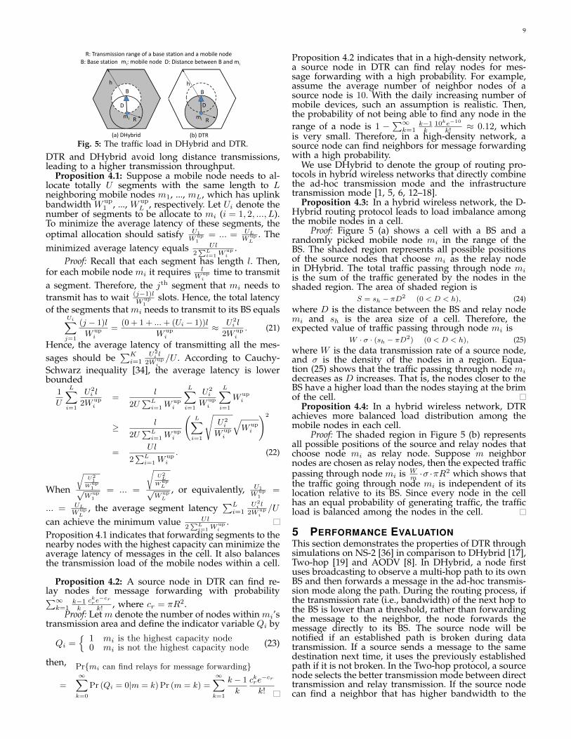
Fig. 5: The traffic load in DHybrid and DTR.
DTR and DHybrid avoid long distance transmissions,leading to a higher transmission throughput.
Proposition 4.1: Suppose a mobile node needs to al-locate totally U segments with the same length to Lneighboring mobile nodes m1, ..., mL, which has uplinkbandwidth W up
1 , ..., W upL , respectively. Let Ui denote the
number of segments to be allocate to mi (i = 1, 2, ..., L).To minimize the average latency of these segments, theoptimal allocation should satisfy U1
Wup1
= ... = UL
WupL
. Theminimized average latency equals Ul
2∑L
i=1Wupi
.Proof: Recall that each segment has length l. Then,
for each mobile node mi it requires lWup
itime to transmit
a segment. Therefore, the jth segment that mi needs totransmit has to wait (j−1)l
Wup1
slots. Hence, the total latencyof the segments that mi needs to transmit to its BS equals
Ui∑j=1
(j − 1)l
W upi
=(0 + 1 + ...+ (Ui − 1))l
W upi
≈ U2i l
2W upi
. (21)
Hence, the average latency of transmitting all the mes-sages should be
∑Ki=1
U2i l
2Wupi/U . According to Cauchy-
Schwarz inequality [34], the average latency is lowerbounded
1
U
L∑i=1
U2i l
2W upi
=l
2U∑L
i=1Wupi
L∑i=1
U2i
W upi
L∑i=1
W upi
≥ l
2U∑L
i=1Wupi
(L∑
i=1
√U2
i
W upi
√W up
i
)2
=Ul
2∑L
i=1Wupi
. (22)
When
√U21
Wup1√
Wup1
= ... =
√U2L
WupL√
WupL
, or equivalently, U1
Wup1
=
... = UL
WupL
, the average segment latency∑Li=1
U2i l
2Wupi/U
can achieve the minimum value Ul2∑L
i=1Wupi
.Proposition 4.1 indicates that forwarding segments to thenearby nodes with the highest capacity can minimize theaverage latency of messages in the cell. It also balancesthe transmission load of the mobile nodes within a cell.
Proposition 4.2: A source node in DTR can find re-lay nodes for message forwarding with probability∑∞k=1
k−1k
ckre−cr
k! , where cr = πR2.Proof: Let m denote the number of nodes within mi’s
transmission area and define the indicator variable Qi by
Qi ={
1 mi is the highest capacity node0 mi is not the highest capacity node (23)
then, Pr{mi can find relays for message forwarding}
=
∞∑k=0
Pr (Qi = 0|m = k) Pr (m = k) =
∞∑k=1
k − 1
k
ckre−cr
k!
Proposition 4.2 indicates that in a high-density network,a source node in DTR can find relay nodes for mes-sage forwarding with a high probability. For example,assume the average number of neighbor nodes of asource node is 10. With the daily increasing number ofmobile devices, such an assumption is realistic. Then,the probability of not being able to find any node in therange of a node is 1 −
∑∞k=1
k−1k
10ke−10
k! ≈ 0.12, whichis very small. Therefore, in a high-density network, asource node can find neighbors for message forwardingwith a high probability.
We use DHybrid to denote the group of routing pro-tocols in hybrid wireless networks that directly combinethe ad-hoc transmission mode and the infrastructuretransmission mode [1, 5, 6, 12–18].
Proposition 4.3: In a hybrid wireless network, the D-Hybrid routing protocol leads to load imbalance amongthe mobile nodes in a cell.
Proof: Figure 5 (a) shows a cell with a BS and arandomly picked mobile node mi in the range of theBS. The shaded region represents all possible positionsof the source nodes that choose mi as the relay nodein DHybrid. The total traffic passing through node miis the sum of the traffic generated by the nodes in theshaded region. The area of shaded region is
S = sh − πD2 (0 < D < h), (24)where D is the distance between the BS and relay nodemi and sh is the area size of a cell. Therefore, theexpected value of traffic passing through node mi is
W · σ · (sh − πD2) (0 < D < h), (25)where W is the data transmission rate of a source node,and σ is the density of the nodes in a region. Equa-tion (25) shows that the traffic passing through node midecreases as D increases. That is, the nodes closer to theBS have a higher load than the nodes staying at the brimof the cell.
Proposition 4.4: In a hybrid wireless network, DTRachieves more balanced load distribution among themobile nodes in each cell.
Proof: The shaded region in Figure 5 (b) representsall possible positions of the source and relay nodes thatchoose node mi as relay node. Suppose m neighbornodes are chosen as relay nodes, then the expected trafficpassing through node mi is W
m ·σ ·πR2 which shows that
the traffic going through node mi is independent of itslocation relative to its BS. Since every node in the cellhas an equal probability of generating traffic, the trafficload is balanced among the nodes in the cell.
5 PERFORMANCE EVALUATIONThis section demonstrates the properties of DTR throughsimulations on NS-2 [36] in comparison to DHybrid [17],Two-hop [19] and AODV [8]. In DHybrid, a node firstuses broadcasting to observe a multi-hop path to its ownBS and then forwards a message in the ad-hoc transmis-sion mode along the path. During the routing process, ifthe transmission rate (i.e., bandwidth) of the next hop tothe BS is lower than a threshold, rather than forwardingthe message to the neighbor, the node forwards themessage directly to its BS. The source node will benotified if an established path is broken during datatransmission. If a source sends a message to the samedestination next time, it uses the previously establishedpath if it is not broken. In the Two-hop protocol, a sourcenode selects the better transmission mode between directtransmission and relay transmission. If the source nodecan find a neighbor that has higher bandwidth to the
10
0
100
200
300
400
500
20 40 60 80 100
Th
rou
gp
ut
per
S-D
pair
(k
bp
s)
Network size
DTRTwo-hopDHybridAODV
Fig. 6: Throughput vs. networksize (simulation).
200
250
300
350
400
450
500
550
600
3 4 5 6
Th
ro
ug
hp
ut
pe
r S
-D
pa
ir (
kb
ps
)
Number of base stations
DTRTwo-hopDHybridAODV
Fig. 7: Throughput vs. numberof BSes.
0
1
2
3
4
5
6
7
8
9
20 40 60 80 100
Dela
y p
er
S-D
pair
(s)
Network size
DTRTwo-hopDHybridAODV
Fig. 8: Delay vs. network size.
1
2
3
4
5
6
3 4 5 6
De
lay p
er
S-D
pa
ir (
s)
Number of base stations
DTRTwo-hopDHybridAODV
Fig. 9: Delay vs. number of B-Ses.
BS than itself, it transmits the message to the neighbor.Otherwise, it directly transmits the message to the BS.
Unless otherwise specified, the simulated networkconsists of 50 mobile nodes and 4 BSes. In the ad-hoccomponent of the hybrid wireless network, mobile nodesare randomly deployed around the BSes in a field of1000×1000 square meters. We used the Distributed Coor-dination Function (DCF) of the IEEE 802.11 as the MAClayer protocol. The transmission range of the cellularinterface was set to 250 meters, and the raw physical linkbandwidth was set to 2Mbits/s. The transmission powerof the ad-hoc interface was set to the minimum valuerequired to keep the network connected for most times,even when nodes are in motion in the network. Then,the influence of the transmission range on differentmethods’ performance is controlled. Specifically, we setthe transmission range through the ad-hoc interface to1.5 times of the average distance between neighboringnodes, which can be obtained by measuring the simu-lated network. We used the two-ray propagation modelfor the physical layer model. Constant bit rate (CBR)was selected as the traffic mode in the experiment with arate of 640kbps. In the experiment, we randomly chose 4source nodes to continuously send messages to random-ly chosen destination nodes. The number of channels foreach BS was set to 10. We set the number of redundantrouting paths b in Section 3.4 to 1. We assumed that therewas no capacity degradation during transmission be-tween BSes. This assumption is realistic considering theadvanced technologies and hardware presently used inwired infrastructure networks. There was no message re-transmission for failed transmissions in the experiments.
We employed the random way-point mobility mod-el [37] to generate the moving direction, speed, andpause duration of each node. In this model, each nodemoves to a random position with a speed randomly cho-sen from (1− 20)m/s. The pause time of each node wasset to 0. We set the number of segments of a message tothe connection degree of the source node. The simulationwarmup time was set to 100s and the simulation timewas set to 1000s. We conducted the experiments 5 timesand used the average value as the final experimentalresult. To make the methods comparable, we did notuse the congestion control algorithm in DTR unlessotherwise indicated.
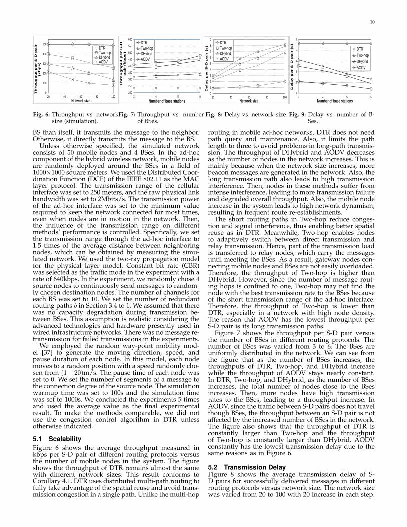
5.1 ScalabilityFigure 6 shows the average throughput measured inkbps per S-D pair of different routing protocols versusthe number of mobile nodes in the system. The figureshows the throughput of DTR remains almost the samewith different network sizes. This result conforms toCorollary 4.1. DTR uses distributed multi-path routing tofully take advantage of the spatial reuse and avoid trans-mission congestion in a single path. Unlike the multi-hop
routing in mobile ad-hoc networks, DTR does not needpath query and maintenance. Also, it limits the pathlength to three to avoid problems in long-path transmis-sion. The throughput of DHybrid and AODV decreasesas the number of nodes in the network increases. This ismainly because when the network size increases, morebeacon messages are generated in the network. Also, thelong transmission path also leads to high transmissioninterference. Then, nodes in these methods suffer fromintense interference, leading to more transmission failureand degraded overall throughput. Also, the mobile nodeincrease in the system leads to high network dynamism,resulting in frequent route re-establishments.
The short routing paths in Two-hop reduce conges-tion and signal interference, thus enabling better spatialreuse as in DTR. Meanwhile, Two-hop enables nodesto adaptively switch between direct transmission andrelay transmission. Hence, part of the transmission loadis transferred to relay nodes, which carry the messagesuntil meeting the BSes. As a result, gateway nodes con-necting mobile nodes and BSes are not easily overloaded.Therefore, the throughput of Two-hop is higher thanDHybrid. However, since the number of message rout-ing hops is confined to one, Two-hop may not find thenode with the best transmission rate to the BSes becauseof the short transmission range of the ad-hoc interface.Therefore, the throughput of Two-hop is lower thanDTR, especially in a network with high node density.The reason that AODV has the lowest throughput perS-D pair is its long transmission paths.
Figure 7 shows the throughput per S-D pair versusthe number of BSes in different routing protocols. Thenumber of BSes was varied from 3 to 6. The BSes areuniformly distributed in the network. We can see fromthe figure that as the number of BSes increases, thethroughputs of DTR, Two-hop, and DHybrid increasewhile the throughput of AODV stays nearly constant.In DTR, Two-hop, and DHybrid, as the number of BSesincreases, the total number of nodes close to the BSesincreases. Then, more nodes have high transmissionrates to the BSes, leading to a throughput increase. InAODV, since the traffic between S-D pairs does not travelthough BSes, the throughput between an S-D pair is notaffected by the increased number of BSes in the network.The figure also shows that the throughput of DTR isconstantly larger than Two-hop and the throughputof Two-hop is constantly larger than DHybrid. AODVconstantly has the lowest transmission delay due to thesame reasons as in Figure 6.
5.2 Transmission DelayFigure 8 shows the average transmission delay of S-D pairs for successfully delivered messages in differentrouting protocols versus network size. The network sizewas varied from 20 to 100 with 20 increase in each step.
11
0
20
40
60
80
100
120
20 40 60 80 100
Co
mm
un
icat
ion
o
verh
ead
(kp
bs)
Network size
DTRDHybridTwo-hopAODV
Fig. 10: Overhead vs. network size
050
100150200250300350400450500
0 5 10 15 20
Tota
l th
rou
gh
pu
t (k
bp
s)
Node moving speed (m/s)
DTRDHybridTwo-hopAODV
Fig. 11: Throughput vs. mobility.
0
500
1000
1500
2000
2500
3000
2 3 4 5 6
Tota
l th
oru
gh
pu
t o
f b
ase
stat
ion
s (k
bp
s)
Number of source nodes
DTRTwo-hopDHybrid
Fig. 12: Throughput of BSes vs. numberof source nodes.
Transmission delay is the amount of time it takes fora message to be transmitted from its source node toits destination node. From the figure, we see that DTRgenerates the smallest delay. In DTR, each source nodefirst divides its messages into smaller segments and thenforwards them to the nearby nodes with the highest ca-pacity, which leads to more balanced transmission loaddistribution among nodes than the previous methods.According to Proposition 4.1, average latency can beminimized when the transmission loads of all the nodesare balanced. Hence, DTR has smaller latency than theprevious methods. The delay of DHybrid is 5-6 timeslarger than DTR. DHybrid uses a single transmissionpath, while DTR uses multiple paths. Recall that we setthe number of segments of a message to the connectiondegree of the source node in DTR. Thus, the ratio ofdelay time of DHybrid to that of DTR equals the averageconnection degree. As the number of nodes in the systemincreases, the connection degree of each node increases,and the increase rate of the ratio grows. This is caused bytwo reasons. First, a higher node density leads to longerpath lengths in DHybrid, resulting in a longer delaybecause of a higher likelihood of link breaks. Second,a higher node density enables a node to quickly findrelay nodes to forward messages in DTR, as indicatedin Proposition 4.2.
DTR also produces a shorter transmission delaythan Two-hop for two reasons. First, the multi-pathparallel routing of DTR saves much transmission timeas shown in Proposition 4.1. Second, the distributedrouting of DTR enables some messages to be forwardedto the destination BS’s neighboring cells with hightransmission rates rather than waiting in the currenthot cell for a transmission channel. We can also observethat Two-hop produces lower delay than DHybrid. Thisis because the delay of DHybird includes the time forestablishing a path and for data transmission. Also,the multi-hop transmission component of DHybridresults in a higher delay due to the queuing delay ineach hop. Because of the long distance transmissionswithout support from an infrastructure network, AODVgenerates the longest delay.
Figure 9 plots the average communication delay perS-D pair for successfully delivered messages versus thenumber of BSes in different routing protocols. The figureshows that the increasing number of BSes in the systemleads to a communication delay decrease between nodesin DTR, Two-hop, and DHybrid, but does not affect thecommunication delay in AODV. In DTR, Two-hop, andDHybrid, as the number of BSes increases, more nodescan stay close to the BSes, leading to fewer communica-tion hops and better transmission links between nodesand BSes. Thus, the transmission delay between thenodes is reduced. Since the communication between S-Dpairs in AODV does not rely on BSes, AODV maintains
constant communication delay. The figure also showsthat the communication delay between S-D pairs followsDTR<Two-hop<DHybrid<AODV for the same reasonas in Figure 8.
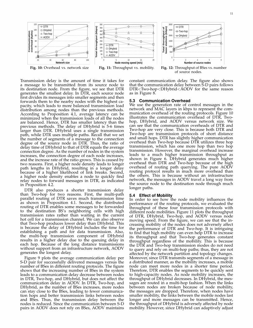
5.3 Communication OverheadWe use the generation rate of control messages in thenetwork and MAC layers in kbps to represent the com-munication overhead of the routing protocols. Figure 10illustrates the communication overhead of DTR, Two-hop, DHybrid, and AODV versus network size. Wecan see that the communication overheads of DTR andTwo-hop are very close. This is because both DTR andTwo-hop are transmission protocols of short distanceand small hops. DTR has slightly higher communicationoverhead than Two-hop because DTR utilizes three hoptransmission, which has one more hop than two hoptransmission. However, the marginal overhead increaseleads to a much higher transmission throughput asshown in Figure 6. DHybrid generates much higheroverhead than DTR and Two-hop because of the highoverhead of routing path querying. The pure AODVrouting protocol results in much more overhead thanthe others. This is because without an infrastructurenetwork, the messages in AODV travel a long way fromthe source node to the destination node through muchlonger paths.
5.4 Effect of MobilityIn order to see how the node mobility influences theperformance of the routing protocols, we evaluated thethroughput of these four transmission protocols withdifferent node mobilities. Figure 11 plots the throughputof DTR, DHybrid, Two-hop, and AODV versus nodemoving speed. From the figure, we can see that the in-creasing mobility of the nodes does not adversely affectthe performance of DTR and Two-hop. It is intriguingto find that high mobility can even help DTR to increaseits throughput and that Two-hop generates constantthroughput regardless of the mobility. This is becausethe DTR and Two-hop transmission modes do not needto query and rely on multi-hop paths; thus, they are notaffected by the network partition and topology changes.Moreover, since DTR transmits segments of a message ina distributed manner, as the mobility increases, a mobilenode can meet more nodes in a shorter time period.Therefore, DTR enables the segments to be quickly sentto high-capacity nodes. As node mobility increases, thethroughput of DHybrid decreases. In DHybrid, the mes-sages are routed in a multi-hop fashion. When the linksbetween nodes are broken because of node mobility,the messages are dropped. Therefore, when nodes havesmaller mobility, the links between the mobile nodes lastlonger and more messages can be transmitted. Hence,the throughput of DHybrid is adversely affected by nodemobility. However, since DHybrid can adaptively adjust
12
350
400
450
500
550
600
20 40 60 80 100
Th
rou
gh
pu
t p
er S
-D
pai
r (k
bp
s)
Network size
1 hop 2 hops3 hops 4 hops
Fig. 13: Throughput vs. number ofhops.
0
100
200
300
400
500
600
700
800
0.2 0.4 0.6 0.8 1 1.2
Ave
rag
e lo
ad p
er
no
de
(kb
ps)
The distance from a mobile node to its base station
DTRDHybridTwo-hop
Fig. 14: Load distribution in a cell.
0
100
200
300
400
500
600
700
1 2 3 4
Th
rou
gh
pu
t o
f a
bas
e st
atio
n (
kbp
s)
Rank of base stations
DTRTwo-hopDHybrid
Fig. 15: Load distribution among BSes.
the routing between the ad-hoc transmission and cellulartransmission, the throughput of DHybrid is much higherthan AODV’s. With no infrastructure network, AODVproduces much lower throughput than the others. Itsthroughput also drops as node mobility increases for thesame reasons as DHybrid.
5.5 Effect of WorkloadWe measured the total throughput of BSes on themessages received by BSes. Figure 12 shows the totalthroughput of the BSes versus the number of sourcenodes. We can see that DTR and Two-hop have muchhigher throughput increase rates than DHybrid. Thisis because in DTR and Two-hop, the number of trans-mission hops from a source node to a BS is small.Meanwhile, each node can adaptively switch betweenrelay transmission and direct transmission based onthe transmission rate of its neighbors. Hence, part of asource node’s transmission load is transferred to a fewrelay nodes, which carry the messages until meeting theBSes. Therefore, the gateway mobile nodes are less likelyto be congested. However, nodes in DHybrid cannotadaptively adjust the next forwarding hop because it ispredetermined in the routing path. Messages are alwaysforwarded to the mobile gateway nodes that are closerto the BSes or that have higher transmission rates. There-fore, these mobile gateway nodes can easily become con-gested as the workload of the system increases, leadingto many message drops. Therefore, when the numberof the source nodes is larger than 4, the throughputof DHybrid remains nearly constant. This is also thereason that the throughput of DHybrid is constantlylower than those of DTR and Two-hop. Additionally,the figure shows that the overall throughput of Two-hopis lower than that of DTR. This is because most of thetraffic in Two-hop is confined to a single cell. When a BSin a cell is congested, the traffic cannot be transferredto other cells. In contrast, DTR’s three-hop distributedforwarding mechanism enables it to distribute the trafficamong the BSes in a balance. Therefore, the BSes inDTR will not become congested easily. In addition, asthe forwarding mechanism gives nodes more flexibilityin choosing relay nodes with higher transmission ratesfor message forwarding to the BSes, the overall BSthroughput in DTR is larger than in Two-hop.
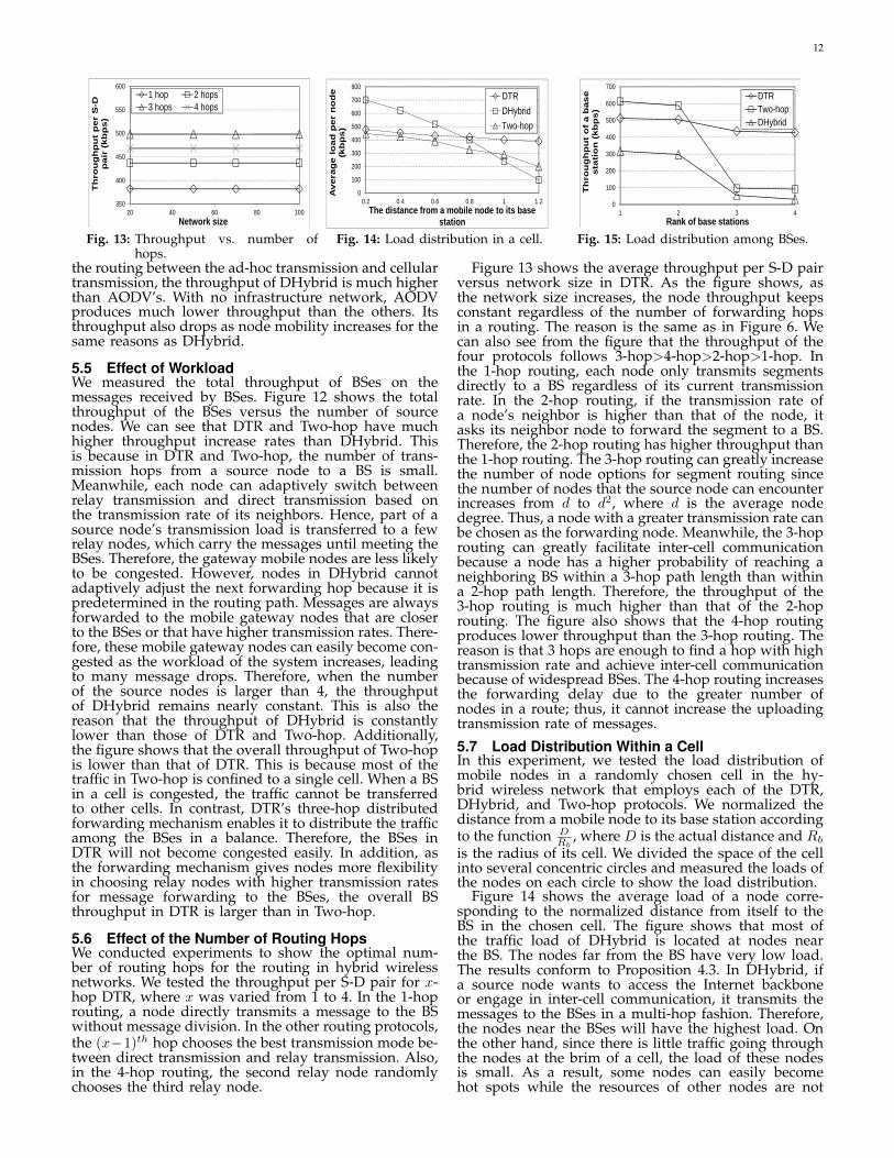
5.6 Effect of the Number of Routing HopsWe conducted experiments to show the optimal num-ber of routing hops for the routing in hybrid wirelessnetworks. We tested the throughput per S-D pair for x-hop DTR, where x was varied from 1 to 4. In the 1-hoprouting, a node directly transmits a message to the BSwithout message division. In the other routing protocols,the (x−1)th hop chooses the best transmission mode be-tween direct transmission and relay transmission. Also,in the 4-hop routing, the second relay node randomlychooses the third relay node.
Figure 13 shows the average throughput per S-D pairversus network size in DTR. As the figure shows, asthe network size increases, the node throughput keepsconstant regardless of the number of forwarding hopsin a routing. The reason is the same as in Figure 6. Wecan also see from the figure that the throughput of thefour protocols follows 3-hop>4-hop>2-hop>1-hop. Inthe 1-hop routing, each node only transmits segmentsdirectly to a BS regardless of its current transmissionrate. In the 2-hop routing, if the transmission rate ofa node’s neighbor is higher than that of the node, itasks its neighbor node to forward the segment to a BS.Therefore, the 2-hop routing has higher throughput thanthe 1-hop routing. The 3-hop routing can greatly increasethe number of node options for segment routing sincethe number of nodes that the source node can encounterincreases from d to d2, where d is the average nodedegree. Thus, a node with a greater transmission rate canbe chosen as the forwarding node. Meanwhile, the 3-hoprouting can greatly facilitate inter-cell communicationbecause a node has a higher probability of reaching aneighboring BS within a 3-hop path length than withina 2-hop path length. Therefore, the throughput of the3-hop routing is much higher than that of the 2-hoprouting. The figure also shows that the 4-hop routingproduces lower throughput than the 3-hop routing. Thereason is that 3 hops are enough to find a hop with hightransmission rate and achieve inter-cell communicationbecause of widespread BSes. The 4-hop routing increasesthe forwarding delay due to the greater number ofnodes in a route; thus, it cannot increase the uploadingtransmission rate of messages.
5.7 Load Distribution Within a CellIn this experiment, we tested the load distribution ofmobile nodes in a randomly chosen cell in the hy-brid wireless network that employs each of the DTR,DHybrid, and Two-hop protocols. We normalized thedistance from a mobile node to its base station accordingto the function D
Rb, where D is the actual distance and Rb
is the radius of its cell. We divided the space of the cellinto several concentric circles and measured the loads ofthe nodes on each circle to show the load distribution.
Figure 14 shows the average load of a node corre-sponding to the normalized distance from itself to theBS in the chosen cell. The figure shows that most ofthe traffic load of DHybrid is located at nodes nearthe BS. The nodes far from the BS have very low load.The results conform to Proposition 4.3. In DHybrid, ifa source node wants to access the Internet backboneor engage in inter-cell communication, it transmits themessages to the BSes in a multi-hop fashion. Therefore,the nodes near the BSes will have the highest load. Onthe other hand, since there is little traffic going throughthe nodes at the brim of a cell, the load of these nodesis small. As a result, some nodes can easily becomehot spots while the resources of other nodes are not
13
0
100
200
300
400
500
600
0 200 400 600 800 1000
Th
rou
gh
pu
t o
f a
bas
e st
atio
n (
kbp
s)
Simulation time (s)
Rank 1Rank 2Rank 3Rank 4
(a) DTR
0
100
200
300
400
500
600
700
800
0 200 400 600 800 1000
Th
rou
gh
pu
t o
f a
bas
e st
atio
n (
kpb
s)
Simulation time (s)
Rank 1Rank 2Rank 3Rank 4
(b) Two-hop
0
50
100
150
200
250
300
350
400
450
0 200 400 600 800 1000
Th
rou
gh
pu
t o
f a
bas
e st
atio
n (
kbp
s)
Simulation time (s)
Rank 1Rank 2Rank 3Rank 4
(c) DHybrid
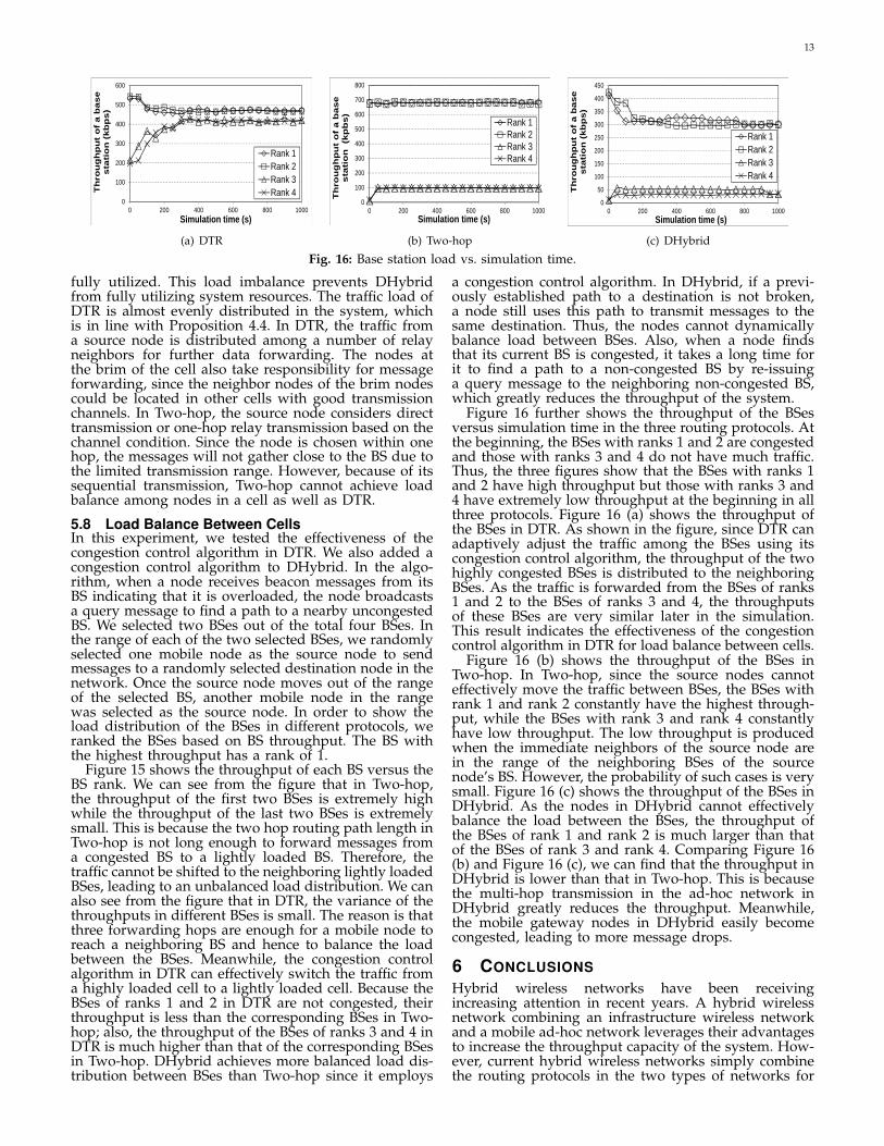
Fig. 16: Base station load vs. simulation time.
fully utilized. This load imbalance prevents DHybridfrom fully utilizing system resources. The traffic load ofDTR is almost evenly distributed in the system, whichis in line with Proposition 4.4. In DTR, the traffic froma source node is distributed among a number of relayneighbors for further data forwarding. The nodes atthe brim of the cell also take responsibility for messageforwarding, since the neighbor nodes of the brim nodescould be located in other cells with good transmissionchannels. In Two-hop, the source node considers directtransmission or one-hop relay transmission based on thechannel condition. Since the node is chosen within onehop, the messages will not gather close to the BS due tothe limited transmission range. However, because of itssequential transmission, Two-hop cannot achieve loadbalance among nodes in a cell as well as DTR.
5.8 Load Balance Between CellsIn this experiment, we tested the effectiveness of thecongestion control algorithm in DTR. We also added acongestion control algorithm to DHybrid. In the algo-rithm, when a node receives beacon messages from itsBS indicating that it is overloaded, the node broadcastsa query message to find a path to a nearby uncongestedBS. We selected two BSes out of the total four BSes. Inthe range of each of the two selected BSes, we randomlyselected one mobile node as the source node to sendmessages to a randomly selected destination node in thenetwork. Once the source node moves out of the rangeof the selected BS, another mobile node in the rangewas selected as the source node. In order to show theload distribution of the BSes in different protocols, weranked the BSes based on BS throughput. The BS withthe highest throughput has a rank of 1.
Figure 15 shows the throughput of each BS versus theBS rank. We can see from the figure that in Two-hop,the throughput of the first two BSes is extremely highwhile the throughput of the last two BSes is extremelysmall. This is because the two hop routing path length inTwo-hop is not long enough to forward messages froma congested BS to a lightly loaded BS. Therefore, thetraffic cannot be shifted to the neighboring lightly loadedBSes, leading to an unbalanced load distribution. We canalso see from the figure that in DTR, the variance of thethroughputs in different BSes is small. The reason is thatthree forwarding hops are enough for a mobile node toreach a neighboring BS and hence to balance the loadbetween the BSes. Meanwhile, the congestion controlalgorithm in DTR can effectively switch the traffic froma highly loaded cell to a lightly loaded cell. Because theBSes of ranks 1 and 2 in DTR are not congested, theirthroughput is less than the corresponding BSes in Two-hop; also, the throughput of the BSes of ranks 3 and 4 inDTR is much higher than that of the corresponding BSesin Two-hop. DHybrid achieves more balanced load dis-tribution between BSes than Two-hop since it employs
a congestion control algorithm. In DHybrid, if a previ-ously established path to a destination is not broken,a node still uses this path to transmit messages to thesame destination. Thus, the nodes cannot dynamicallybalance load between BSes. Also, when a node findsthat its current BS is congested, it takes a long time forit to find a path to a non-congested BS by re-issuinga query message to the neighboring non-congested BS,which greatly reduces the throughput of the system.
Figure 16 further shows the throughput of the BSesversus simulation time in the three routing protocols. Atthe beginning, the BSes with ranks 1 and 2 are congestedand those with ranks 3 and 4 do not have much traffic.Thus, the three figures show that the BSes with ranks 1and 2 have high throughput but those with ranks 3 and4 have extremely low throughput at the beginning in allthree protocols. Figure 16 (a) shows the throughput ofthe BSes in DTR. As shown in the figure, since DTR canadaptively adjust the traffic among the BSes using itscongestion control algorithm, the throughput of the twohighly congested BSes is distributed to the neighboringBSes. As the traffic is forwarded from the BSes of ranks1 and 2 to the BSes of ranks 3 and 4, the throughputsof these BSes are very similar later in the simulation.This result indicates the effectiveness of the congestioncontrol algorithm in DTR for load balance between cells.
Figure 16 (b) shows the throughput of the BSes inTwo-hop. In Two-hop, since the source nodes cannoteffectively move the traffic between BSes, the BSes withrank 1 and rank 2 constantly have the highest through-put, while the BSes with rank 3 and rank 4 constantlyhave low throughput. The low throughput is producedwhen the immediate neighbors of the source node arein the range of the neighboring BSes of the sourcenode’s BS. However, the probability of such cases is verysmall. Figure 16 (c) shows the throughput of the BSes inDHybrid. As the nodes in DHybrid cannot effectivelybalance the load between the BSes, the throughput ofthe BSes of rank 1 and rank 2 is much larger than thatof the BSes of rank 3 and rank 4. Comparing Figure 16(b) and Figure 16 (c), we can find that the throughput inDHybrid is lower than that in Two-hop. This is becausethe multi-hop transmission in the ad-hoc network inDHybrid greatly reduces the throughput. Meanwhile,the mobile gateway nodes in DHybrid easily becomecongested, leading to more message drops.
6 CONCLUSIONSHybrid wireless networks have been receivingincreasing attention in recent years. A hybrid wirelessnetwork combining an infrastructure wireless networkand a mobile ad-hoc network leverages their advantagesto increase the throughput capacity of the system. How-ever, current hybrid wireless networks simply combinethe routing protocols in the two types of networks for
14
data transmission, which prevents them from achievinghigher system capacity. In this paper, we propose aDistributed Three-hop Routing (DTR) data routing pro-tocol that integrates the dual features of hybrid wirelessnetworks in the data transmission process. In DTR, asource node divides a message stream into segments andtransmits them to its mobile neighbors, which furtherforward the segments to their destination through aninfrastructure network. DTR limits the routing pathlength to three, and always arranges for high-capacitynodes to forward data. Unlike most existing routingprotocols, DTR produces significantly lower overheadby eliminating route discovery and maintenance. Inaddition, its distinguishing characteristics of shortpath length, short-distance transmission, and balancedload distribution provide high routing reliability andefficiency. DTR also has a congestion control algorithmto avoid load congestion in BSes in the case ofunbalanced traffic distributions in networks. Theoreticalanalysis and simulation results show that DTR candramatically improve the throughput capacity andscalability of hybrid wireless networks due to its highscalability, efficiency, and reliability and low overhead.
ACKNOWLEDGEMENTSThis research was supported in part by U.S. NSF grantsIIS-1354123, CNS-1254006, CNS-1249603, CNS-1049947,CNS-0917056 and CNS-1025652, Microsoft Research Fac-ulty Fellowship 8300751, and the United States Depart-ment of Defense 238866. We would like to thank Mr.Kang Chen for his help in addressing review comments.
REFERENCES[1] H Luo, R. Ramjee, P. Sinha, L. Li, and S. Lu. Ucan: A unified cell
and ad-hoc network architecture. In Proc. of MOBICOM, 2003.[2] P. K. McKinley, H. Xu, A. H. Esfahanian, and L. M. Ni. Unicast-
based multicast communication in wormhole-routed direct net-works. TPDS, 1992.
[3] H. Wu, C. Qiao, S. De, and O. Tonguz. Integrated cell and ad hocrelaying systems: iCAR. J-SAC, 2001.
[4] Y. H. Tam, H. S. Hassanein, S. G. Akl, and R. Benkoczi. Optimalmulti-hop cellular architecture for wireless communications. InProc. of LCN, 2006.
[5] Y. D. Lin and Y. C. Hsu. Multi-hop cellular: A new architecturefor wireless communications. In Proc. of INFOCOM, 2000.
[6] P. T. Oliver, Dousse, and M. Hasler. Connectivity in ad hoc andhybrid networks. In Proc. of INFOCOM, 2002.
[7] E. P. Charles and P. Bhagwat. Highly dynamic destinationsequenced distance vector routing (DSDV) for mobile computers.In Proc. of SIGCOMM, 1994.
[8] C. Perkins, E. Belding-Royer, and S. Das. RFC 3561: Ad hocon demand distance vector (AODV) routing. Technical report,Internet Engineering Task Force, 2003.
[9] D. B. Johnson and D. A. Maltz. Dynamic source routing in adhoc wireless networks. IEEE Mobile Computing, 1996.
[10] V. D. Park and M. Scott Corson. A highly adaptive distributedrouting algorithm for mobile wireless networks. In Proc. ofINFOCOM, 1997.
[11] R. S. Chang, W. Y. Chen, and Y. F. Wen. Hybrid wireless networkprotocols. IEEE Transaction on Vehicular Technology, 2003.
[12] G. N. Aggelou and R. Tafazolli. On the relaying capacity of next-generation gsm cellular networks. IEEE Personal CommunicationsMagazine, 2001.
[13] T. Rouse, I. Band, and S. McLaughlin. Capacity and powerinvestigation of opportunity driven multiple access (ODMA)networks in TDD-CDMA based systems. In Proc. of ICC, 2002.
[14] H. Y. Hsieh and R. Sivakumar. On Using the Ad-hoc NetworkModel in Wireless Packet Data Networks. In Proc. of MOBIHOC,2002.
[15] L. M. Feeney, B. Cetin, D. Hollos, M. Kubisch, S. Mengesha, andH. Karl. Multi-rate relaying for performance improvement in ieee802.11 wlans. In Proc. of WWIC, 2007.
[16] J. Cho and Z. J. Haas. On the throughput enhancement of thedownstream channel in cellular radio networks through multihoprelaying. IEEE JSAC, 2004.
[17] B. Liu, Z. Liu, and D. Towsley. On the capacity of hybrid wirelessnetworks. In Proc. of INFOCOM, 2003.
[18] H. Y. Hsieh and R. Sivakumar. A hybrid network model forwireless packet data networks. In Proc. of GLOBECOM, 2002.
[19] Y. Wei and D. Gitlin. Two-hop-relay architecture for next-generation WWAN/WLAN integration. IEEE Wireless Commu-nication, 2004.
[20] X. J. Li, B. C. Seet, and P. H. J. Chong. Multihop cellular networks:Technology and economics. Computer Networks, 2008.
[21] B. Bengfort, W. Zhang, and X. Du. Efficient resource allocation inhybrid wireless networks. In Proc. of WCNC, 2011.
[22] P. Thulasiraman and X. Shen. Interference aware resource alloca-tion for hybrid hierarchical wireless networks. Computer Networks,54(13):2271–2280, 2010.
[23] K. Akkarajitsakul, E. Hossain, and D. Niyato. Cooperative packetdelivery in hybrid wireless mobile networks: A coalitional gameapproach. IEEE Trans. Mob. Comput., 12(5):840–854, 2013.
[24] T. Liu, M. Rong, P. Li, D. Yu, Y. Xue, and E. Schulz. Radio resourceallocation in two-hop cellular relaying network. In Proc. of VTC,2006.
[25] T. Liu, M. Rong, H. Shi, D. Yu, Y. Xue, and E. Schulz. Reusepartitioning in fixed two-hop cellular relaying network. In Proc.of WCNC, 2006.
[26] L. Guan, J. Zhang, J. Li, G. Liu, and P. Zhang. Spectral efficientfrequency allocation scheme in multihop cellular network. InProc. of VTC, 2007.
[27] D. M. Shila, Y. Cheng, and T. Anjali. Throughput and delayanalysis of hybrid wireless networks with multi-hop uplinks. InProc. of INFOCOM, 2011.
[28] B. Liu, P. Thiran, and D. Towsley. Capacity of a wireless ad hocnetwork with infrastructure. In Proc. of Mobihoc, 2007.
[29] C. Wang, X. Li, C. Jiang, S. Tang, and Y. Liu. Multicast throughputfor hybrid wireless networks under gaussian channel model.TMC, 10(6):839–852, 2011.
[30] A. G. Valko. Cellular ip: A new approach to internet host mobility.ACM Computer Comminication, 1999.
[31] C. Sarr, C. Chaudet, G. Chelius, and I. G. Lassous. A Node-Based Available Bandwidth Evaluation In IEEE 802.11 Ad HocNetworks. IJPEDS, 00(00):1–21, 2005.
[32] X. P. Costa, M. T. Moreno, and H. Hartenstein. A simulation studyon the performance of hierarchical mobile ipv6. In Proc. of ITC,2003.
[33] P. Gupta and P. R. Kumar. The capacity of wireless networks.IEEE TIT, 2000.
[34] L. B. Koralov and Y. G. Sinai. Theory of probability and randomprocesses. Berlin New York Springer, 2007.
[35] H. Y. Hsieh and R. Sivakumar. Performance comparison ofcellular and multi-hop wireless networks: A quantitative study.In Proc. of SIGMETRIC, 2001.
[36] The network simulator - ns-2. http://www.isi.edu/nsnam/ns/.[37] M. Grossglauser and D. Tse. Mobility increases the capacity of
ad hoc wireless networks. In Proc. of TON, 2002.
Haiying Shen received the BS degree in Com-puter Science and Engineering from Tongji U-niversity, China in 2000, and the MS and Ph.D.degrees in Computer Engineering from WayneState University in 2004 and 2006, respectively.She is currently an Associate Professor in theDepartment of Electrical and Computer Engi-neering at Clemson University. Her researchinterests include distributed computer systemsand computer networks, with an emphasis oncontent delivery networks, mobile computing,wireless sensor networks, and cloud. She isa Microsoft Faculty Fellow of 2010, a senior
member of the IEEE and a member of the ACM.
15
[7] Y. Yao, X. Tang, and E. Lim, “In-network processing of nearestneighbor queries for wireless sensor networks,” in Proc. of DAS-FAA06, 2006.
[8] R. Szewczyk, J. Polastre, A. Mainwaring, and D. Culler, “Lessonsfrom a Sensor Network Expedition,” in Proc. of EWSN, 2004.
[9] C. Intanagonwiwat, R. Govindan, and D. Estrin, “Directed Diffu-sion: A Scalable and Robust Communication Paradigm for SensorNetworks,” in Proc. of Mobicom, 2000.
[10] W. Zhang, G. Cao, and T. L. Porta, “Data Dissemination withRing-Based Index for Wireless Sensor Networks,” in Proc. of ICNP,2003, pp. 305–314.
[11] S. Madden, M. J. Franklin, and J. M. H. W. Hong, “TAG: a TinyAGgregation Service for Ad-Hoc Sensor Networks,” in Proc. ofOSDI, 2002.
[12] F. Ye and G. Zhong, “GRAdient Broadcast: A Robust Data Deliv-ery Protocol for Large Scale Sensor Networks,” WINET, 2005.
[13] H. Luo, F. Ye, J. Cheng, S. Lu, and L. Zhang, “Ttdd: Two-tier datadissemination in large-scale sensor networks,” Wireless Networks,vol. 11, pp. 161–175, 2002.
[14] S. Ratnasamy, B. Karp, S. Shenker, D. Estrin, R. Grovindan,L. Yin, and F. Yu, “Data-centric storage in sensornet with ght: Ageographic hash table,” in Proc. of MONET, 2003.
[15] S. Ratnasamy, B. Karp, S. Shenker, D. Estrin, and L. Yin, “Data-centric storage in sensornets with GHT, a geographic hash table,”MONET, vol. 8, pp. 427–442, 2003.
[16] X. Li, Y. J. Kim, and W. Hong, “Multi-dimensional range queriesin sensor networks,” in Proc. of SenSys, 2003.
[17] D. Ganesan, “DIMENSIONS: Why do we need a new datahandling architecture for sensor networks,” in Proc. of the ACMHotNets, 2002, pp. 143–148.
[18] D. Ganesan, A. Cerpa, Y. Yu, D. Estrin, W. Ye, and J. Zhao,“Networking issues in wireless sensor networks,” JPDC, 2004.
[19] B. Greenstein, D. Estrin, R. Govindan, S. Ratnasamy, andS. Shenker, “Difs: A distributed index for features in sensor net-works,” in Proc. of SNPA, 2003.
[20] J. Li, J. Jannotti, D. S. J. De, C. David, R. Karger, and R. Morris, “Ascalable location service for geographic ad hoc routing,” in Proc. ofMobiCom, 2000.
[21] J. Newsome and D. Song, “GEM: Graph EMbedding for routingand data-centric storage in sensor networks without geographicinformation,” in Proc. of SenSys, 2003.
[22] A. Caruso, S. Chessa, S. De, and R. Urpi, “GPS free coordinateassignment and routing in wireless sensor networks,” in Proc. ofIEEE INFOCOM, 2005, pp. 150–160.
[23] P. Desnoyers, D. Ganesan, and P. Shenoy, “Tsar: A two tiersensor storage architecture using interval skip graphs,” in Proc.of SenSys05. ACM Press, 2005, pp. 39–50.
[24] C. T. Ee and S. Ratnasamy, “Practical data-centric storage,” in Proc.of NSDI, 2006.
[25] M. Aly, K. Pruhs, and P. K. Chrysanthis, “KDDCS: A load-balanced in-network data-centric storage scheme in sensor net-work,” in Proc. of CIKM, 2006, pp. 317–326.
[26] F. Bian, X. Li, R. Govindan, and S. Schenker, “Using hierarchicallocation names for scalable routing and rendezvous in wirelesssensor networks,” in Proc. of SenSys, 2004, pp. 305–306.
[27] J. Xu, X. Tang, and W. chien Lee, “A new storage scheme forapproximate location queries in object tracking sensor networks,”IEEE TPDS, vol. 19, pp. 262–275, 2008.
[28] M. Li and Y. Liu, “Rendered path: range-free localization inanisotropic sensor networks with holes,” in Proc. of MobiCom, 2007.
[29] H. Shen, T. Li, and T. Schweiger, “An Efficient Similarity SearchingScheme Based on Locality Sensitive Hashing,” in Proc. of ICDT,2008.
[30] D. Karger, E. Lehman, T. Leighton, M. Levine, D. Lewin, andR. Panigrahy, “Consistent Hashing and Random Trees: DistributedCaching Protocols for Relieving Hot Spots on the World WideWeb,” in Proc. of STOC, 1997, pp. 654–663.
[31] W. Nejdl, W. Siberski, M. Wolpers, and C. Schmnitz, “Routingand clustering in schema-based super peer networks,” in Proc. ofIPTPS, 2003.
[32] P. A. Bernstein, F. Giunchiglia, A. Kementsietsidis, J. Mylopoulos,L. Serafini, and I. Zaihrayeu, “Data management for peer-to-peercomputing: A vision,” in Proc. of WebDB, 2002.
[33] A. Y. Halevy, Z. G. Ives, P. Mork, and I. Tatarinov, “Piazza: Datamanagement infrastructure for semantic web applications,” in Proc.of WWW, 2003.
[34] “In how many ways can m balls be distributed into n boxes?”http://www.fen.bilkent.edu.tr/ otekman/disc/usef.pdf.
[35] G. Wang, G. Cao, T. L. Porta, and W. Zhang, “Sensor relocationin mobile sensor networks,” in Proc. of IEEE INFOCOM, 2005.
[36] L. Hu and D. Evans, “Localization for mobile sensor networks,”in Proc. of MobiCom, 2004.
[37] F. Liu, X. Cheng, D. Hua, and D. Chen, “Location discovery forsensor networks with short range beacons,” IJAHUC, 2009.
[38] R. Fonseca, S. Ratnasamy, J. Zhao, and C. T. Ee, “Beacon vectorrouting: scalable point-to-point routing in wireless sensornets,” inProc. of NSDI, 2005.
[39] N. Bulusu, J. Heidemann, and D. Estrin, “Gps-Less Low-CostOutdoor Localization For Very Small Devices,” IEEE Personal Com-munications Magazine, vol. 7, no. 5, pp. 28–34, 2000.
[40] “The one simulator. http://www.netlab.tkk.fi/.”[41] H. Shen, T. Li, L. Zhao, and Z. Li, “SDS: Distributed Spatial-
Temporal Similarity Data Storage in Wireless Sensor Networks,”in Proc. of ICCCN, 2009.
Haiying Shen received the BS degree in Com-puter Science and Engineering from Tongji Uni-versity, China in 2000, and the MS and Ph.D.degrees in Computer Engineering from WayneState University in 2004 and 2006, respectively.She is currently an Assistant Professor in theDepartment of Electrical and Computer Engi-neering, and the Director of the Pervasive Com-munications Laboratory of Clemson University.Her research interests include distributed com-puter systems and computer networks, with an
emphasis on peer-to-peer and content delivery networks, mobile com-puting, wireless sensor networks, and grid computing. Her researchwork has been published in top journals and conferences in theseareas. She was the Program Co-Chair for a number of internationalconferences and member of the Program Committees of many leadingconferences. She is a member of the IEEE and ACM. She is MicrosoftResearch Faculty Fellow of 2010.
Lianyu Zhao received the BS and MS degreesin Computer Science from Jilin University, China.He is currently a Ph.D. student in the Depart-ment of Electrical and Computer Engineeringof Clemson University. His research interestsinclude wireless sensor network, routing proto-cols, applications and security issues in P2Pnetworks.
Ze Li received the BS degree in Electronics andInformation Engineering from Huazhong Univer-sity of Science and Technology, China, in 2007.He is currently a Ph.D. student in the Depart-ment of Electrical and Computer Engineeringof Clemson University. His research interestsinclude distributed networks, with an emphasison peer-to-peer and content delivery networks,wireless multi-hop cellular networks, game the-ory and data mining. He is a student member ofIEEE.
Ze Li received the BS degree in Electronicsand Information Engineering from Huazhong U-niversity of Science and Technology, China, in2007 and the Ph.D. degree in the Department ofElectrical and Computer Engineering of Clem-son University, in 2012. His research interestsinclude distributed networks, with an emphasison content delivery networks, wireless multi-hopcellular networks, game theory and data mining.
Chenxi Qiu received the BS degree in Telecom-munication Engineering from Xidian University,China, in 2009. He currently is a Ph.D. studentin the Department of Electrical and ComputerEngineering at Clemson University, SC, UnitedStates. His research interests include sensornetworks and wireless networks.