Embed Size (px)
Citation preview
Ap
Ta
b
c
a
ARRAA
KFSLNTLF
1
ksaphfpmesapttna
tT
h0
Precision Engineering 40 (2015) 249–260
Contents lists available at ScienceDirect
Precision Engineering
jo ur nal ho me p age: www.elsev ier .com/ locate /prec is ion
flexure-based electromagnetic nanopositioning actuator withredictable and re-configurable open-loop positioning resolution
at Joo Teoa,∗, Guilin Yangb, I-Ming Chenc
Mechatronics Group, Singapore Institute of Manufacturing Technology, Singapore 638075, SingaporeNingbo Institute of Materials Technology and Engineering, Chinese Academy of Sciences, Zhejiang Province 315201, ChinaSchool of Mechanical and Aerospace Engineering, Nanyang Technological University, Singapore 639798, Singapore
r t i c l e i n f o
rticle history:eceived 30 April 2013eceived in revised form 3 December 2014ccepted 24 December 2014vailable online 7 January 2015
eywords:
a b s t r a c t
This paper presents a novel cylindrical-shaped Flexure-based Electromagnetic Linear Actuator (FELA)that exhibits predictable and re-configurable open-loop positioning resolution. By combining contactlessLorentz-force actuation and frictionless flexure-based supporting bearings, it produces high repeatablemotion and sub-micron positioning resolution. In this paper, the design concept of this cylindrical-shapedFELA will be introduced. It focuses on the modeling of the flexure-based supporting bearings, the thermalmodeling of the electromagnetic module, and the unique characteristics of FELA, i.e., predictable and re-configurable open-loop positioning resolution. A prototype was developed to evaluate the performance
lexure jointsemi-analytic modelorentz-force actuationanopositioning actuatorhermal modelingumped capacitance model
and demonstrate these unique characteristics of this new class of nanopositioning actuator.© 2015 Elsevier Inc. All rights reserved.
lexure modeling
. Introduction
An actuator with nano-positioning capabilities has been theey technology in nano-/micro-scale manufacturing processesuch as nano-imprint lithography, fibre optics alignment, MEMSssembly, nano-scale machining, etc. Among various types of nano-ositioning actuators, the solid-state piezoelectric (PZT) actuatorsave been the most popular choice due to their large actuating
orce and high stiffness. However, PZT actuators have limited dis-lacements that make them unsuitable to drive high-precisionanipulators targeted for large traveling range [1]. Although some
xisting high-precision positioning actuators are able to eliminateuch limitations, the displacement amplification techniques thatre used within these actuators inherit other drawbacks. For exam-le, PZT-driven actuators that use high-pitch screw actuating-shafto achieve millimeters of displacement have poor repeatability due
o backlash and Coulomb friction [2]. Others that use the mag-etostrictive clamping technique [3], the inchworm clamping [4],nd the impact-force method [5] to drive an internal shaft for∗ Corresponding author at: Mechatronics Group, Singapore Institute of Manufac-uring Technology, 71 Nanyang Drive, Singapore 638075, Singapore.el.: +65 67938285.
E-mail address: [email protected] (T.J. Teo).
ttp://dx.doi.org/10.1016/j.precisioneng.2014.12.006141-6359/© 2015 Elsevier Inc. All rights reserved.
displacement amplification purposes have low payload capacities.In addition, the slow response speed makes these actuators ineffi-cient for high speed applications.
Electromagnetic driving scheme has the potential of deliver-ing millimeters of traveling range with nanometers of positioningresolution. Actuators of such frictionless drive, i.e., voice-coil lin-ear actuators and solenoid actuators, have also been employed inhigh-precision manipulation [6,7]. However, the voice-coil actuatorproduces relatively small output forces (or poor force sensitivity).Although the moving magnet actuator offers good dynamic behav-ior and good heat dissipation, the magnetic force attraction dueto the external iron casing causes the output force to be incon-stant throughout the entire displacement stroke [8]. A solenoidactuator offers good force sensitivity but is unable to achieve a con-stant output force throughout its allowable traveling range due tothe nonlinearity between force and displacement [9]. Furthermore,magnetization on the ferromagnetic stator introduces nonlinearmagnetic hysteresis that leads to inaccuracy in nanometric posi-tioning tracking [10]. The drawbacks of existing nano-positioningactuators motivated the development of a Flexure-based Electro-magnetic Linear Actuator (FELA) [11]. FELA is formed through a
marriage between an electromagnetic (EM) driving scheme andthe flexure joints to achieve a few millimeters of displacement,large continuous thrust force, and a direct-force control capability.From past literatures [12,11], FELA was able to deliver a positioning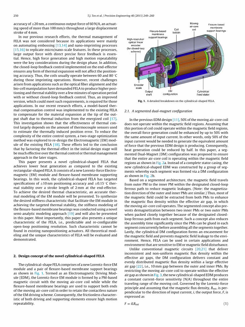
2 ngineering 40 (2015) 249–260
ais
Fo[ltwteidabtwvamtpTttcmutba
armbsmTmtatsicofed
2
maumflooir
50 T.J. Teo et al. / Precision E
ccuracy of ±20 nm, a continuous output force of 60 N/A, an actuat-ng speed of more than 100 mm/s throughout a large displacementtroke of 4 mm.
In our previous research efforts, the thermal management ofELA was not considered because its applications were mainlyn automating embossing [13,14] and nano-imprinting processes15,16] to replicate micro/nano-scale features. In these processes,arge output force with direct precise force feedback is essen-ial. Hence, high force generation and high motion repeatabilityere the key considerations during the design phase. In addition,
he closed-loop feedback control implemented on the end-effectornsures any form of thermal expansion will not affect the position-ng accuracy. Thus, the coils usually operate between 60 and 80 ◦Curing those imprinting operations. However, recent challengesrisen from applications such as the optical fiber alignment and theio-cell manipulation have demanded FELA to produce higher posi-ioning and thermal stability over a few minutes of operation periodith or without closed-loop feedback control. Thus, an improved
ersion, which could meet such requirements, is required for thosepplications. In our recent research efforts, a model-based ther-al compensation control was implemented to the existing FELA
o compensate for the material expansion at the tip of the out-ut shaft due to thermal induction from the energized coil [17].his investigation shows that the effectiveness of thermal con-rol largely depends on the amount of thermocouple sensors usedo estimate the thermally induced position error. To reduce theomplexity of the entire control system, a two-stage optimizationethod was explored to re-design the Electromagnetic (EM) mod-
le of the existing FELA [18]. These efforts led to the conclusionhat by factoring the thermal effect in the initial design stage wille much effective over the thermal control or thermal managementpproach in the later stages.
This paper presents a novel cylindrical-shaped FELA thatchieves lower heat generation as compared to the existingectangular-shaped FELA. It consists of a new Lorentz-force Electro-agnetic (EM) module and flexure-based membrane supporting
earings. In this work, the cylindrical-shaped FELA has targetedpecifications of ±10 nm positioning accuracy and ±0.15 ◦C ther-al stability over a stroke length of 2 mm at the end-effector.
o achieve the desired thermal characteristic, an accurate ther-al modeling of the EM module will be presented. To synthesize
he desired stiffness characteristic that facilitate the EM module inchieving the targeted thermal stability, the stiffness modeling ofhe flexure-based membrane bearings was conducted using a novelemi-analytic modeling approach [19] and will also be presentedn this paper. Most importantly, this paper also presents a uniqueharacteristic of the FELA, i.e., predictable and re-configurablepen-loop positioning resolution. Such characteristic cannot beound in existing nanopositioning actuators. All theoretical mod-ling and the unique characteristics of FELA will be evaluated andemonstrated.
. Design concept of the novel cylindrical-shaped FELA
The cylindrical-shape FELA comprises of a new Lorentz-force EModule and a pair of flexure-based membrane support bearings
s shown in Fig. 1. Termed as an Electromagnetic Driving Mod-le (EDM), the Lorentz-force EM module is formed by a PM-basedagnetic circuit with the moving air-core coil while while the
exure-based membrane bearings are used to support both ends
f the moving air-core coil in order to retain the contactless naturef the EM driving scheme. Consequently, the frictionless character-stic of both driving and supporting elements ensure high motionepeatability.Fig. 1. A detailed breakdown on the cylindrical-shaped FELA.
2.1. A segmented dual-magnet configuration
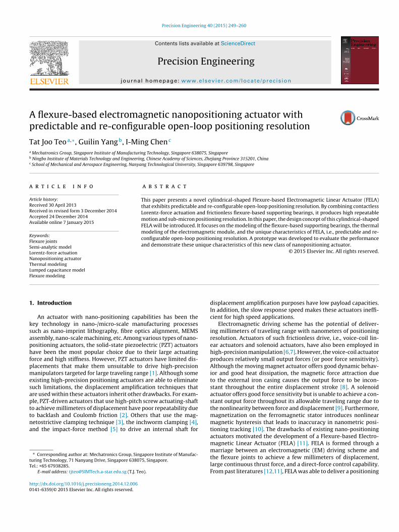
In the previous EDM design [11], 50% of the moving air-core coildoes not operate within the magnetic field regions. Assuming thatthis portion of coil could operate within the magnetic field regions,the overall force generation could be enhanced by up to 50% withthe same amount of input current. In other words, only 50% of theinput current would be needed to generate the equivalent amountof force that the previous EDM design is producing. Consequently,heat generation could be reduced by half. In this paper, a seg-mented Dual-Magnet (DM) configuration was proposed to ensurethat the entire air-core coil is operating within the magnetic fieldregions as shown in Fig. 2a. Instead of a complete stator casing, thenew cylindrical-shaped EDM was constructed by a group of seg-ments whereby each segment was formed via a DM configurationas shown in Fig. 2b.
Based on a segmented architecture, the magnetic field travelsfrom outer PM to the inner PM within the designated closed-loopferrous path to reduce magnetic leakages. (Note: the magnetiza-tion direction of the outer and inner PMs are similar.) Thus, most ofthe magnetic field could be extracted from both PMs to enhancethe magnetic flux density within the effective air gap, in whichthe moving air-core coil operates. The segmented concept also pre-vents demagnetization between two inner PMs or two outer PMswhen packed closely together because of the designated closed-loop ferrous path from each segment. Such a concept also reducesthe assembly time significantly since the PMs can be glued in eachsegment concurrently before assembling all the segments together.Lastly, the cylindrical DM configuration forms an encasement forthe magnetic field and prevents magnetic field leakage to the envi-ronment. Hence, FELA can be used in certain applications andenvironment that are sensitive to EM or magnetic field disturbance.
Unlike conventional magnetic circuits [20,21] that deliverinconsistent and non-uniform magnetic flux density within theeffective air gaps, the DM configuration delivers constant andevenly distributed magnetic flux density within a large effectiveair gap [22], i.e., 10 mm gap between the outer and inner PMs. Byrestricting the moving air-core coil to operate within the effectiveair gap as shown in Fig. 3, the new cylindrical-shaped EDM producesa constant current–force sensitivity (N/A) throughout the entiretraveling range of the moving coil. Governed by the Lorentz-forceprinciple and assuming that the magnetic flux density, Bext, is per-
pendicular to the direction of input current, i, the output force, F, isexpressed asF ≡ iLBext (1)
T.J. Teo et al. / Precision Engineering 40 (2015) 249–260 251
of seg
wtacso[E
2
ssfabsflfssratasebrob
K
w
Fc
Fig. 2. (a) A cylindrical-shaped EDM constructed by a group
here L represents the total coil length operating within the effec-ive air gap. Aided by the segmented DM configuration, Eq. (1)lso suggest that the new cylindrical-shaped EDM provides a linearurrent–force relationship due to the constant magnetic flux den-ity within the effective air gap. The modeling and optimizationf the DM configuration have been presented in recent literatures18,22]. This paper mainly focuses on the thermal modeling of theDM.
.2. Flexure-based membrane support bearings
To retain the contactless nature of the Lorentz-force EM drivingcheme, flexure joints are used to develop frictionless bearings toupport the moving air-core coil as illustrated in Fig. 3. Unlike otherrictionless bearings such as the air bearings, the magnetic bearings,nd the hydrostatic/hydrodynamic bearings, these flexure-basedearings do not require any air/electrical/fluid source, expensiveensors, nor complex control systems to function. As a result,exure-based bearings are simple, inexpensive and maintenance-
ree. In addition, a well-designed flexure-based bearing ensures lowtiffness in the actuating direction while providing relatively highertiffness in all non-actuating directions within the allowable travelange. Unlike the previous FELA design, which used clamping blocksnd stainless steel shims to form such flexure-based bearings [11],he new cylindrical-shaped FELA adopts a flexure-based membranerchitecture that is formed by a single monolithic-cut stainlessteel sheet. Consequently, the absence of the clamping blocks alsoliminates these secondary moving masses. As the flexure-basedearings only operate within the elastic region of the material, theelationship between the force generated from the EDM and theutput displacement, ı, of the air-core coil translator is assumed toe linear and expressed as
= F
ı(2)
here K represents the stiffness of the flexure-based bearings.
ig. 3. Working principle of FELA: flexure-based bearings supporting a moving air-ore coil that operates within the effective air gap of a DM configuration.
mented DM configuration (US patent appl. #2013/990,219).
2.3. Re-configurable open-loop positioning resolution
Due to the linear current–force relationship of the EDM andthe linear force–displacement relationship of the flexure-basedbearings, the open-loop positioning resolution of FELA becomespredictable and re-configurable. (Note: an open-loop positioningresolution is defined as the achievable resolution based on thesmallest controllable input current.) By combining the Ohm’s Law,i.e., V = IR, with Eqs. (1) and (2), the open-loop positioning resolutionof FELA is given as
ı = V(Rcoil + Rext)−1LBext
K(3)
where Rcoil represents the resistance of the air-core coil and Rext
represents the resistance of the external resistor. Eq. (3) suggeststwo different approaches to enhance the open-loop positioning res-olution of FELA. First, by increasing the stiffness of flexure-basedbearings to enhance the positioning resolution for the same amountof driving force. Second, by adding external resistors between thevoltage supply and the system to reduce the amount of currentvia the voltage mode. Flexibility to reconfigure the open-loop posi-tioning resolution is an unique characteristic of FELA and will bedemonstrated in later part of this paper.
3. Thermal modeling of the cylindrical-shaped EDM
Thermal modeling and analysis plays a crucial role in syn-thesizing the cylindrical-shaped EDM to achieve a desired powerconsumption and temperature characteristic for continuous forcegeneration. In this work, the lumped capacitance modelingapproach was used to obtain the mathematical representation ofthe thermal performance of the EDM.
3.1. Power management
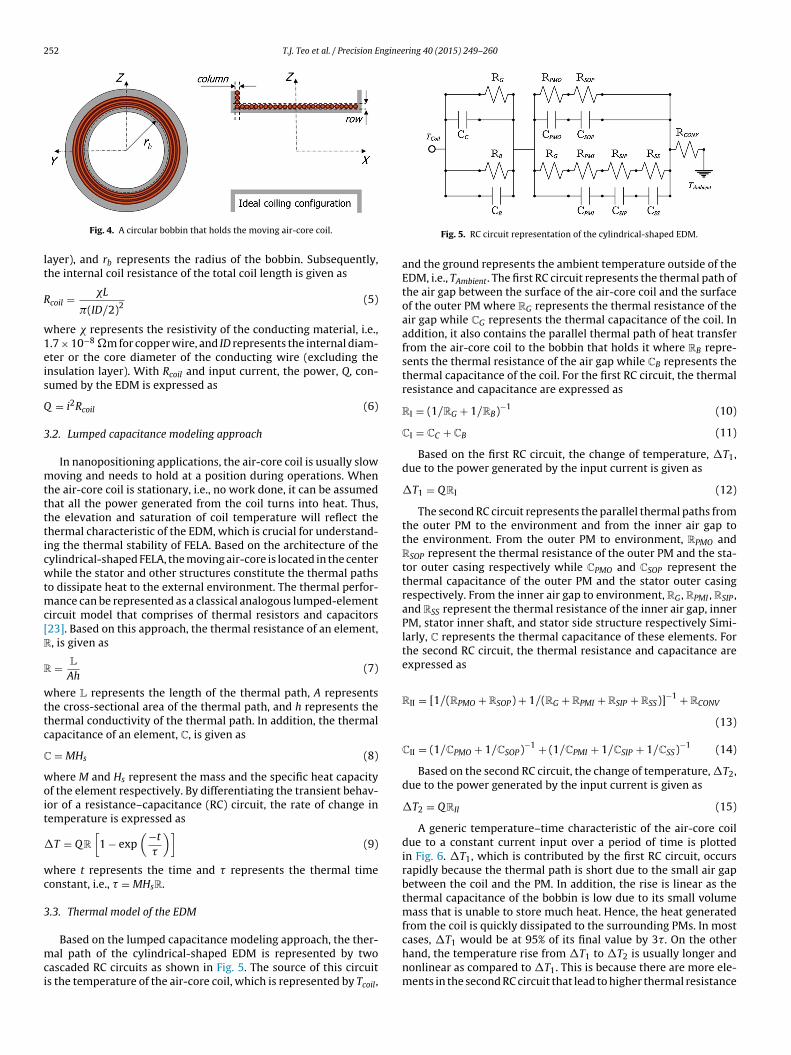
From Eq. (1), the output force is a function of input current, mag-netic flux density and the total coil length operating within the airgap. Based on the architecture of the cylindrical-shaped EDM, thecoils are wound on a circular bobbin to form the moving air-corecoil as shown in Fig. 4. Assuming that the coiling is ideal, the totalnumber of rows will represent the total number of layers whileeach column will represent the number of turns per layer. Basedon this configuration, the total coil length is represented as
L = 2�Ntpl[rbNl + OD(Nl + 1)(Nl/2)] (4)
where Nl represents the number of layers of coil within a bob-bin, Ntpl represents the number of turns per layer, OD representsthe overall diameter of the conducting coil wire (with insulation
252 T.J. Teo et al. / Precision Engineering 40 (2015) 249–260
lt
R
w1eis
Q
3
mtttticwtmc[R
R
wttc
C
woit
�
wc
3
mci
Fig. 4. A circular bobbin that holds the moving air-core coil.
ayer), and rb represents the radius of the bobbin. Subsequently,he internal coil resistance of the total coil length is given as
coil = �L
�(ID/2)2(5)
here � represents the resistivity of the conducting material, i.e.,.7 × 10−8 �m for copper wire, and ID represents the internal diam-ter or the core diameter of the conducting wire (excluding thensulation layer). With Rcoil and input current, the power, Q, con-umed by the EDM is expressed as
= i2Rcoil (6)
.2. Lumped capacitance modeling approach
In nanopositioning applications, the air-core coil is usually slowoving and needs to hold at a position during operations. When
he air-core coil is stationary, i.e., no work done, it can be assumedhat all the power generated from the coil turns into heat. Thus,he elevation and saturation of coil temperature will reflect thehermal characteristic of the EDM, which is crucial for understand-ng the thermal stability of FELA. Based on the architecture of theylindrical-shaped FELA, the moving air-core is located in the centerhile the stator and other structures constitute the thermal paths
o dissipate heat to the external environment. The thermal perfor-ance can be represented as a classical analogous lumped-element
ircuit model that comprises of thermal resistors and capacitors23]. Based on this approach, the thermal resistance of an element,, is given as
= L
Ah(7)
here L represents the length of the thermal path, A representshe cross-sectional area of the thermal path, and h represents thehermal conductivity of the thermal path. In addition, the thermalapacitance of an element, C, is given as
= MHs (8)
here M and Hs represent the mass and the specific heat capacityf the element respectively. By differentiating the transient behav-or of a resistance–capacitance (RC) circuit, the rate of change inemperature is expressed as
T = Q R
[1 − exp
(−t
�
)](9)
here t represents the time and � represents the thermal timeonstant, i.e., � = MHsR.
.3. Thermal model of the EDM
Based on the lumped capacitance modeling approach, the ther-al path of the cylindrical-shaped EDM is represented by two
ascaded RC circuits as shown in Fig. 5. The source of this circuits the temperature of the air-core coil, which is represented by Tcoil,
Fig. 5. RC circuit representation of the cylindrical-shaped EDM.
and the ground represents the ambient temperature outside of theEDM, i.e., TAmbient. The first RC circuit represents the thermal path ofthe air gap between the surface of the air-core coil and the surfaceof the outer PM where RG represents the thermal resistance of theair gap while CG represents the thermal capacitance of the coil. Inaddition, it also contains the parallel thermal path of heat transferfrom the air-core coil to the bobbin that holds it where RB repre-sents the thermal resistance of the air gap while CB represents thethermal capacitance of the coil. For the first RC circuit, the thermalresistance and capacitance are expressed as
RI = (1/RG + 1/RB)−1 (10)
CI = CC + CB (11)
Based on the first RC circuit, the change of temperature, �T1,due to the power generated by the input current is given as
�T1 = QRI (12)
The second RC circuit represents the parallel thermal paths fromthe outer PM to the environment and from the inner air gap tothe environment. From the outer PM to environment, RPMO andRSOP represent the thermal resistance of the outer PM and the sta-tor outer casing respectively while CPMO and CSOP represent thethermal capacitance of the outer PM and the stator outer casingrespectively. From the inner air gap to environment, RG , RPMI , RSIP ,and RSS represent the thermal resistance of the inner air gap, innerPM, stator inner shaft, and stator side structure respectively Simi-larly, C represents the thermal capacitance of these elements. Forthe second RC circuit, the thermal resistance and capacitance areexpressed as
RII = [1/(RPMO + RSOP) + 1/(RG + RPMI + RSIP + RSS)]−1 + RCONV
(13)
CII = (1/CPMO + 1/CSOP)−1 + (1/CPMI + 1/CSIP + 1/CSS)−1 (14)
Based on the second RC circuit, the change of temperature, �T2,due to the power generated by the input current is given as
�T2 = QRII (15)
A generic temperature–time characteristic of the air-core coildue to a constant current input over a period of time is plottedin Fig. 6. �T1, which is contributed by the first RC circuit, occursrapidly because the thermal path is short due to the small air gapbetween the coil and the PM. In addition, the rise is linear as thethermal capacitance of the bobbin is low due to its small volumemass that is unable to store much heat. Hence, the heat generatedfrom the coil is quickly dissipated to the surrounding PMs. In most
cases, �T1 would be at 95% of its final value by 3�. On the otherhand, the temperature rise from �T1 to �T2 is usually longer andnonlinear as compared to �T1. This is because there are more ele-ments in the second RC circuit that lead to higher thermal resistance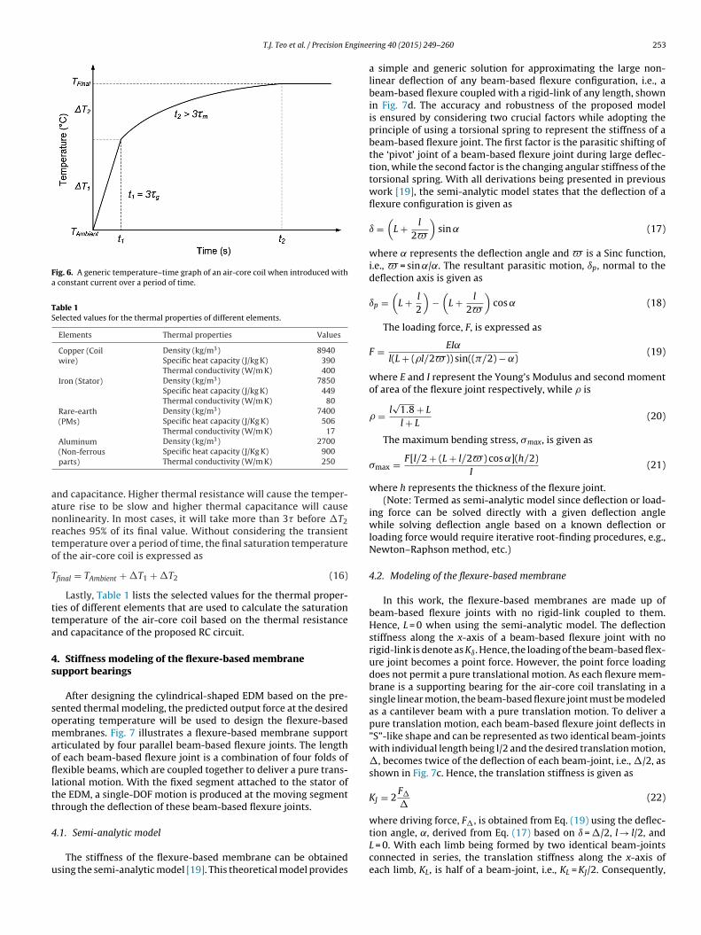
T.J. Teo et al. / Precision Enginee
Fig. 6. A generic temperature–time graph of an air-core coil when introduced witha constant current over a period of time.
Table 1Selected values for the thermal properties of different elements.
Elements Thermal properties Values
Copper (Coilwire)
Density (kg/m3) 8940Specific heat capacity (J/kg K) 390Thermal conductivity (W/m K) 400
Iron (Stator) Density (kg/m3) 7850Specific heat capacity (J/kg K) 449Thermal conductivity (W/m K) 80
Rare-earth(PMs)
Density (kg/m3) 7400Specific heat capacity (J/Kg K) 506Thermal conductivity (W/m K) 17
Aluminum Density (kg/m3) 2700
aanrto
T
tta
4s
somaoflltt
4
u
(Non-ferrousparts)
Specific heat capacity (J/Kg K) 900Thermal conductivity (W/m K) 250
nd capacitance. Higher thermal resistance will cause the temper-ture rise to be slow and higher thermal capacitance will causeonlinearity. In most cases, it will take more than 3� before �T2eaches 95% of its final value. Without considering the transientemperature over a period of time, the final saturation temperaturef the air-core coil is expressed as
final = TAmbient + �T1 + �T2 (16)
Lastly, Table 1 lists the selected values for the thermal proper-ies of different elements that are used to calculate the saturationemperature of the air-core coil based on the thermal resistancend capacitance of the proposed RC circuit.
. Stiffness modeling of the flexure-based membraneupport bearings
After designing the cylindrical-shaped EDM based on the pre-ented thermal modeling, the predicted output force at the desiredperating temperature will be used to design the flexure-basedembranes. Fig. 7 illustrates a flexure-based membrane support
rticulated by four parallel beam-based flexure joints. The lengthf each beam-based flexure joint is a combination of four folds ofexible beams, which are coupled together to deliver a pure trans-
ational motion. With the fixed segment attached to the stator ofhe EDM, a single-DOF motion is produced at the moving segmenthrough the deflection of these beam-based flexure joints.
.1. Semi-analytic model
The stiffness of the flexure-based membrane can be obtainedsing the semi-analytic model [19]. This theoretical model provides
ring 40 (2015) 249–260 253
a simple and generic solution for approximating the large non-linear deflection of any beam-based flexure configuration, i.e., abeam-based flexure coupled with a rigid-link of any length, shownin Fig. 7d. The accuracy and robustness of the proposed modelis ensured by considering two crucial factors while adopting theprinciple of using a torsional spring to represent the stiffness of abeam-based flexure joint. The first factor is the parasitic shifting ofthe ‘pivot’ joint of a beam-based flexure joint during large deflec-tion, while the second factor is the changing angular stiffness of thetorsional spring. With all derivations being presented in previouswork [19], the semi-analytic model states that the deflection of aflexure configuration is given as
ı =(
L + l
2�
)sin ̨ (17)
where ̨ represents the deflection angle and � is a Sinc function,i.e., � = sin ˛/˛. The resultant parasitic motion, ıp, normal to thedeflection axis is given as
ıp =(
L + l
2
)−
(L + l
2�
)cos ˛ (18)
The loading force, F, is expressed as
F = EI˛
l(L + (�l/2�)) sin((�/2) − ˛)(19)
where E and I represent the Young’s Modulus and second momentof area of the flexure joint respectively, while � is
� = l√
1.8 + L
l + L(20)
The maximum bending stress, max, is given as
max = F[l/2 + (L + l/2�) cos ˛](h/2)I
(21)
where h represents the thickness of the flexure joint.(Note: Termed as semi-analytic model since deflection or load-
ing force can be solved directly with a given deflection anglewhile solving deflection angle based on a known deflection orloading force would require iterative root-finding procedures, e.g.,Newton–Raphson method, etc.)
4.2. Modeling of the flexure-based membrane
In this work, the flexure-based membranes are made up ofbeam-based flexure joints with no rigid-link coupled to them.Hence, L = 0 when using the semi-analytic model. The deflectionstiffness along the x-axis of a beam-based flexure joint with norigid-link is denote as Kı. Hence, the loading of the beam-based flex-ure joint becomes a point force. However, the point force loadingdoes not permit a pure translational motion. As each flexure mem-brane is a supporting bearing for the air-core coil translating in asingle linear motion, the beam-based flexure joint must be modeledas a cantilever beam with a pure translation motion. To deliver apure translation motion, each beam-based flexure joint deflects in”S”-like shape and can be represented as two identical beam-jointswith individual length being l/2 and the desired translation motion,�, becomes twice of the deflection of each beam-joint, i.e., �/2, asshown in Fig. 7c. Hence, the translation stiffness is given as
KJ = 2F�
�(22)
where driving force, F�, is obtained from Eq. (19) using the deflec-
tion angle, ˛, derived from Eq. (17) based on ı = �/2, l → l/2, andL = 0. With each limb being formed by two identical beam-jointsconnected in series, the translation stiffness along the x-axis ofeach limb, KL, is half of a beam-joint, i.e., KL = KJ/2. Consequently,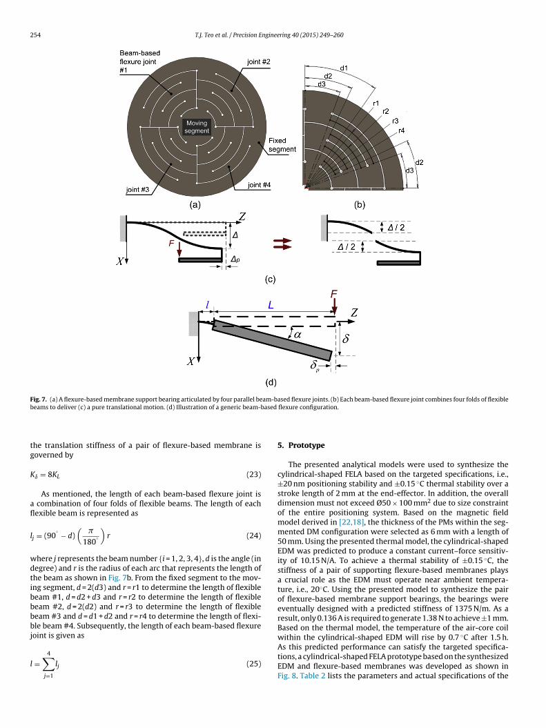
254 T.J. Teo et al. / Precision Engineering 40 (2015) 249–260
Fig. 7. (a) A flexure-based membrane support bearing articulated by four parallel beam-based flexure joints. (b) Each beam-based flexure joint combines four folds of flexibleb ased
tg
K
afl
l
wdtibbbbj
l
eams to deliver (c) a pure translational motion. (d) Illustration of a generic beam-b
he translation stiffness of a pair of flexure-based membrane isoverned by
ı = 8KL (23)
As mentioned, the length of each beam-based flexure joint is combination of four folds of flexible beams. The length of eachexible beam is represented as
j = (90◦ − d)
(�
180◦
)r (24)
here j represents the beam number {i = 1, 2, 3, 4}, d is the angle (inegree) and r is the radius of each arc that represents the length ofhe beam as shown in Fig. 7b. From the fixed segment to the mov-ng segment, d = 2(d3) and r = r1 to determine the length of flexibleeam #1, d = d2 + d3 and r = r2 to determine the length of flexibleeam #2, d = 2(d2) and r = r3 to determine the length of flexibleeam #3 and d = d1 + d2 and r = r4 to determine the length of flexi-le beam #4. Subsequently, the length of each beam-based flexure
oint is given as
=4∑
j=1
lj (25)
flexure configuration.
5. Prototype
The presented analytical models were used to synthesize thecylindrical-shaped FELA based on the targeted specifications, i.e.,±20 nm positioning stability and ±0.15 ◦C thermal stability over astroke length of 2 mm at the end-effector. In addition, the overalldimension must not exceed Ø50 × 100 mm2 due to size constraintof the entire positioning system. Based on the magnetic fieldmodel derived in [22,18], the thickness of the PMs within the seg-mented DM configuration were selected as 6 mm with a length of50 mm. Using the presented thermal model, the cylindrical-shapedEDM was predicted to produce a constant current–force sensitiv-ity of 10.15 N/A. To achieve a thermal stability of ±0.15 ◦C, thestiffness of a pair of supporting flexure-based membranes playsa crucial role as the EDM must operate near ambient tempera-ture, i.e., 20◦C. Using the presented model to synthesize the pairof flexure-based membrane support bearings, the bearings wereeventually designed with a predicted stiffness of 1375 N/m. As aresult, only 0.136 A is required to generate 1.38 N to achieve ±1 mm.Based on the thermal model, the temperature of the air-core coilwithin the cylindrical-shaped EDM will rise by 0.7 ◦C after 1.5 h.
As this predicted performance can satisfy the targeted specifica-tions, a cylindrical-shaped FELA prototype based on the synthesizedEDM and flexure-based membranes was developed as shown inFig. 8. Table 2 lists the parameters and actual specifications of the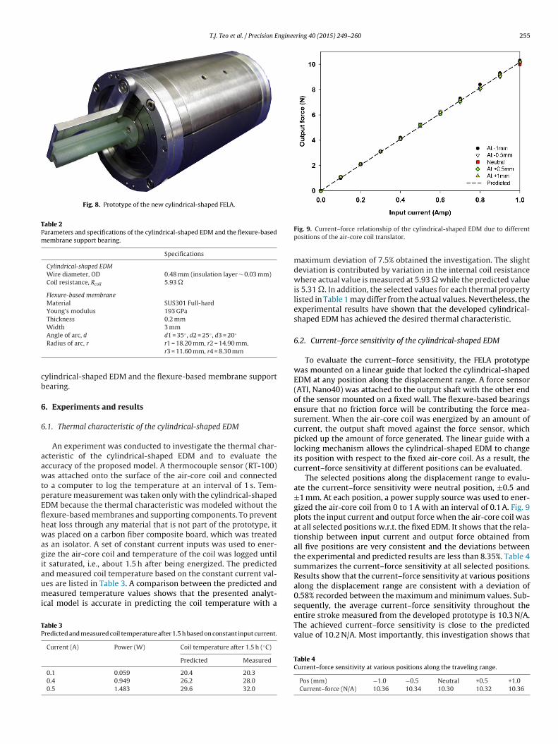
T.J. Teo et al. / Precision Engineering 40 (2015) 249–260 255
Fig. 8. Prototype of the new cylindrical-shaped FELA.
Table 2Parameters and specifications of the cylindrical-shaped EDM and the flexure-basedmembrane support bearing.
Specifications
Cylindrical-shaped EDMWire diameter, OD 0.48 mm (insulation layer ∼ 0.03 mm)Coil resistance, Rcoil 5.93 �
Flexure-based membraneMaterial SUS301 Full-hardYoung’s modulus 193 GPaThickness 0.2 mmWidth 3 mm
◦ ◦ ◦
cb
6
6
aawtpEflhwagiaumi
TP
Angle of arc, d d1 = 35 , d2 = 25 , d3 = 20Radius of arc, r r1 = 18.20 mm, r2 = 14.90 mm,
r3 = 11.60 mm, r4 = 8.30 mm
ylindrical-shaped EDM and the flexure-based membrane supportearing.
. Experiments and results
.1. Thermal characteristic of the cylindrical-shaped EDM
An experiment was conducted to investigate the thermal char-cteristic of the cylindrical-shaped EDM and to evaluate theccuracy of the proposed model. A thermocouple sensor (RT-100)as attached onto the surface of the air-core coil and connected
o a computer to log the temperature at an interval of 1 s. Tem-erature measurement was taken only with the cylindrical-shapedDM because the thermal characteristic was modeled without theexure-based membranes and supporting components. To preventeat loss through any material that is not part of the prototype, itas placed on a carbon fiber composite board, which was treated
s an isolator. A set of constant current inputs was used to ener-ize the air-core coil and temperature of the coil was logged untilt saturated, i.e., about 1.5 h after being energized. The predicted
nd measured coil temperature based on the constant current val-es are listed in Table 3. A comparison between the predicted andeasured temperature values shows that the presented analyt-cal model is accurate in predicting the coil temperature with a
able 3redicted and measured coil temperature after 1.5 h based on constant input current.
Current (A) Power (W) Coil temperature after 1.5 h (◦C)
Predicted Measured
0.1 0.059 20.4 20.30.4 0.949 26.2 28.00.5 1.483 29.6 32.0
Fig. 9. Current–force relationship of the cylindrical-shaped EDM due to differentpositions of the air-core coil translator.
maximum deviation of 7.5% obtained the investigation. The slightdeviation is contributed by variation in the internal coil resistancewhere actual value is measured at 5.93 � while the predicted valueis 5.31 �. In addition, the selected values for each thermal propertylisted in Table 1 may differ from the actual values. Nevertheless, theexperimental results have shown that the developed cylindrical-shaped EDM has achieved the desired thermal characteristic.
6.2. Current–force sensitivity of the cylindrical-shaped EDM
To evaluate the current–force sensitivity, the FELA prototypewas mounted on a linear guide that locked the cylindrical-shapedEDM at any position along the displacement range. A force sensor(ATI, Nano40) was attached to the output shaft with the other endof the sensor mounted on a fixed wall. The flexure-based bearingsensure that no friction force will be contributing the force mea-surement. When the air-core coil was energized by an amount ofcurrent, the output shaft moved against the force sensor, whichpicked up the amount of force generated. The linear guide with alocking mechanism allows the cylindrical-shaped EDM to changeits position with respect to the fixed air-core coil. As a result, thecurrent–force sensitivity at different positions can be evaluated.
The selected positions along the displacement range to evalu-ate the current–force sensitivity were neutral position, ±0.5 and±1 mm. At each position, a power supply source was used to ener-gized the air-core coil from 0 to 1 A with an interval of 0.1 A. Fig. 9plots the input current and output force when the air-core coil wasat all selected positions w.r.t. the fixed EDM. It shows that the rela-tionship between input current and output force obtained fromall five positions are very consistent and the deviations betweenthe experimental and predicted results are less than 8.35%. Table 4summarizes the current–force sensitivity at all selected positions.Results show that the current–force sensitivity at various positionsalong the displacement range are consistent with a deviation of0.58% recorded between the maximum and minimum values. Sub-sequently, the average current–force sensitivity throughout the
entire stroke measured from the developed prototype is 10.3 N/A.The achieved current–force sensitivity is close to the predictedvalue of 10.2 N/A. Most importantly, this investigation shows thatTable 4Current–force sensitivity at various positions along the traveling range.
Pos (mm) −1.0 −0.5 Neutral +0.5 +1.0Current–force (N/A) 10.36 10.34 10.30 10.32 10.36
256 T.J. Teo et al. / Precision Engineering 40 (2015) 249–260
Ffl
ts
6
ean2porbogtpflttvptoflttw
6
tfl
6
bt
I
wr
current–force sensitivity, i.e., 10.3 N/A, the step displacements ofFELA were predicted and listed in Table 5 based on different bear-ing thickness and input current values. The experimental results
Table 5Reconfiguring the open-loop step displacement of FELA using flexure-based bear-ings with different thickness.
Current (�A) Predicted Measured (avg) Error (%)
0.3 mm thickness: Step displacement (nm)22 45.43 42.69 6.4244 89.46 86.00 4.0266 133.83 130.69 2.4188 177.16 174.37 1.60
110 221.18 212.43 4.12
0.4 mm thickness: Step displacement (nm)22 19.15 20.56 6.8444 37.59 37.66 0.1766 56.17 54.36 3.3288 74.74 74.98 0.31
110 93.17 94.89 1.82
0.5 mm thickness: Step displacement (nm)22 9.88 10.00 1.17
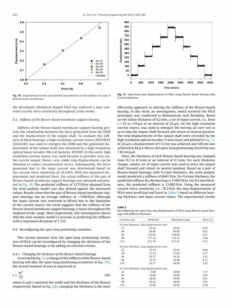
ig. 10. Experimental results and theoretical prediction on the stiffness of a pair ofexure-based membranes.
he developed cylindrical-shaped FELA has achieved a near con-tant current–force sensitivity throughout 2 mm stroke.
.3. Stiffness of the flexure-based membrane support bearing
Stiffness of the flexure-based membrane support bearing gov-rns the relationship between the force generated from the EDMnd the displacement of the output shaft. To evaluate the stiff-ess of these bearings, a high resolution current source (KEITHLEY24/2243) was used to energize the EDM and the generated dis-lacement of the output shaft was measured by a high resolutionptical linear encoder (MicroE Systems, M3500). In this work, highesolution current source was used because it provides very sta-le current output. Hence, very stable step displacements can bebtained to reduce measurement errors. Subsequently, the forceenerated due to the input current was determined based onhe current–force sensitivity of 10.3 N/A. With the measured dis-lacement and predicted force, the actual stiffness of the pair ofexure-based membrane support bearings was obtained and plot-ed in Fig. 10. The predicted stiffness of 1375 N/m obtained fromhe semi-analytic model was also plotted against the measuredalues. Results show that the pair of flexure-based membrane sup-ort bearings has an average stiffness of ≈1398 N/m. Althoughhe input current was restricted to 80 mA due to the limitationf the current source, the trend suggests that the stiffness of theexure-based membrane support bearings is linear throughout theargeted stroke range. Most importantly, this investigation showshat the semi-analytic model is accurate in predicting the stiffnessith a maximum deviation of 7.15%.
.4. Reconfiguring the open-loop positioning resolution
This section presents how the open-loop positioning resolu-ion of FELA can be reconfigured by changing the thickness of theexure-based bearings or by adding an external resistor.
.4.1. Changing the thickness of the flexure-based bearingsGoverned by Eq. (3), a change in the stiffness of the flexure-based
earing will alter the open-loop positioning resolution. In Eq. (19),he second moment of area is expressed as
3
= bt
12(26)
here b and t represent the width and the thickness of the flexureespectively. Based on Eq. (26), changing the thickness is the most
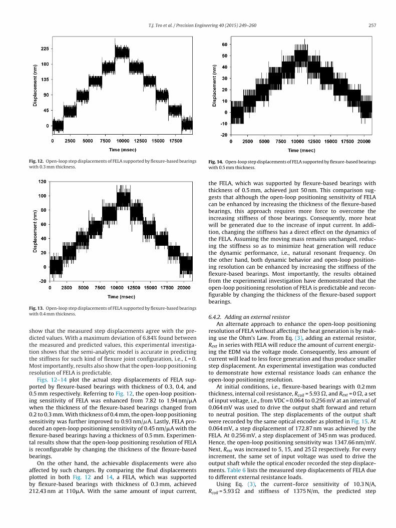
Fig. 11. Open-loop step displacements of FELA using flexure-based bearing with0.2 mm thickness.
effectively approach in altering the stiffness of the flexure-basedbearing. In this work, an investigation, which involved the FELAprototype, was conducted to demonstrate such flexibility. Basedon the initial thickness of 0.2 mm, a set of input current, i.e., fromi = 22 to 110 �A at an interval of 22 �A, via the high resolutioncurrent source, was used to energize the moving air-core coil soas to step the output shaft forward and return to neutral position.The step displacements of the output shaft were recorded by thehigh resolution optical encoder (5 nm/count) and plotted in Fig. 11.At 22 �A, a displacement of 172 nm was achieved and 345 nm wasachieved at 44 �A. Hence, the open-loop positioning sensitivity was7.82 nm/�A.
Next, the thickness of each flexure-based bearing was changedfrom 0.2 to 0.5 mm at an interval of 0.1 mm. For each thicknesschange, similar set of input current was used to drive the outputshaft forward and return to neutral position. Based on a pair offlexure-based bearings with 0.3 mm thickness, the semi-analyticmodel predicted a stiffness of 4641 N/m. For 0.4 mm thickness, thepredicted stiffness for the bearings is 11003 N/m. For 0.5 mm thick-ness, the predicted stiffness is 21485 N/m. Using the measured
44 19.48 20.00 2.6266 28.92 30.00 3.6188 38.42 40.00 3.95
110 47.86 50.00 4.28
T.J. Teo et al. / Precision Engineering 40 (2015) 249–260 257
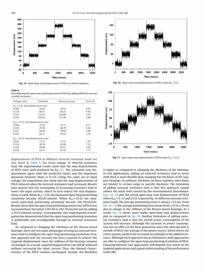
Fig. 12. Open-loop step displacements of FELA supported by flexure-based bearingswith 0.3 mm thickness.
Fw
sdtttMr
p0iw0sdfltib
apb2
ments. Table 6 lists the measured step displacements of FELA due
ig. 13. Open-loop step displacements of FELA supported by flexure-based bearingsith 0.4 mm thickness.
how that the measured step displacements agree with the pre-icted values. With a maximum deviation of 6.84% found betweenhe measured and predicted values, this experimental investiga-ion shows that the semi-analytic model is accurate in predictinghe stiffness for such kind of flexure joint configuration, i.e., L = 0.
ost importantly, results also show that the open-loop positioningesolution of FELA is predictable.
Figs. 12–14 plot the actual step displacements of FELA sup-orted by flexure-based bearings with thickness of 0.3, 0.4, and.5 mm respectively. Referring to Fig. 12, the open-loop position-
ng sensitivity of FELA was enhanced from 7.82 to 1.94 nm/�Ahen the thickness of the flexure-based bearings changed from
.2 to 0.3 mm. With thickness of 0.4 mm, the open-loop positioningensitivity was further improved to 0.93 nm/A. Lastly, FELA pro-uced an open-loop positioning sensitivity of 0.45 nm/�A with theexure-based bearings having a thickness of 0.5 mm. Experimen-al results show that the open-loop positioning resolution of FELAs reconfigurable by changing the thickness of the flexure-basedearings.
On the other hand, the achievable displacements were alsoffected by such changes. By comparing the final displacements
lotted in both Fig. 12 and 14, a FELA, which was supportedy flexure-based bearings with thickness of 0.3 mm, achieved12.43 nm at 110�A. With the same amount of input current,Fig. 14. Open-loop step displacements of FELA supported by flexure-based bearingswith 0.5 mm thickness.
the FELA, which was supported by flexure-based bearings withthickness of 0.5 mm, achieved just 50 nm. This comparison sug-gests that although the open-loop positioning sensitivity of FELAcan be enhanced by increasing the thickness of the flexure-basedbearings, this approach requires more force to overcome theincreasing stiffness of those bearings. Consequently, more heatwill be generated due to the increase of input current. In addi-tion, changing the stiffness has a direct effect on the dynamics ofthe FELA. Assuming the moving mass remains unchanged, reduc-ing the stiffness so as to minimize heat generation will reducethe dynamic performance, i.e., natural resonant frequency. Onthe other hand, both dynamic behavior and open-loop position-ing resolution can be enhanced by increasing the stiffness of theflexure-based bearings. Most importantly, the results obtainedfrom the experimental investigation have demonstrated that theopen-loop positioning resolution of FELA is predictable and recon-figurable by changing the thickness of the flexure-based supportbearings.
6.4.2. Adding an external resistorAn alternate approach to enhance the open-loop positioning
resolution of FELA without affecting the heat generation is by mak-ing use the Ohm’s Law. From Eq. (3), adding an external resistor,Rext in series with FELA will reduce the amount of current energiz-ing the EDM via the voltage mode. Consequently, less amount ofcurrent will lead to less force generation and thus produce smallerstep displacement. An experimental investigation was conductedto demonstrate how external resistance loads can enhance theopen-loop positioning resolution.
At initial conditions, i.e., flexure-based bearings with 0.2 mmthickness, internal coil resistance, Rcoil = 5.93 �, and Rext = 0 �, a setof input voltage, i.e., from VDC = 0.064 to 0.256 mV at an interval of0.064 mV was used to drive the output shaft forward and returnto neutral position. The step displacements of the output shaftwere recorded by the same optical encoder as plotted in Fig. 15. At0.064 mV, a step displacement of 172.87 nm was achieved by theFELA. At 0.256 mV, a step displacement of 345 nm was produced.Hence, the open-loop positioning sensitivity was 1347.66 nm/mV.Next, Rext was increased to 5, 15, and 25 � respectively. For everyincrement, the same set of input voltage was used to drive theoutput shaft while the optical encoder recorded the step displace-
to different external resistance loads.Using Eq. (3), the current–force sensitivity of 10.3 N/A,
Rcoil = 5.93 � and stiffness of 1375 N/m, the predicted step
258 T.J. Teo et al. / Precision Engineering 40 (2015) 249–260
Fig. 15. Open-loop step displacements of FELA at initial conditions.
Table 6Reconfiguring the open-loop step displacement of FELA by adding different externalvariable resistance.
Voltage (mV) Predicted Measured (avg) Error (%)
Rext = 5 �: Step displacement (nm)0.064 43.43 43.02 0.950.128 88.37 89.23 0.980.192 125.81 128.84 2.410.256 168.50 171.99 2.08
Rext = 15 �: Step displacement (nm)0.064 23.22 25.11 8.170.128 45.68 46.78 2.420.191 68.90 70.94 2.960.256 92.11 95.52 3.70
Rext = 25 �: Step displacement (nm)0.064 15.73 15.52 1.29
dalopdvFhlmssRiagil
btttuwt
Fig. 16. Open-loop step displacements of FELA when Rext = 5 �.
0.128 30.70 28.46 7.320.192 46.80 44.77 4.360.256 62.53 61.43 1.77
isplacements of FELA at different external resistance loads arelso listed in Table 6. For every change of external resistanceoad, the experimental results show that the step displacementsf FELA were well predicted by Eq. (3). The measured step dis-lacements agree with the predicted values and the maximumeviation between them is 8.17%. Using the same set of inputoltage, the experiment also show that the step displacements ofELA reduced when the external resistance load increased. Resultsave proven that the assumption of increasing resistance load to
ower the input current, which in turn reduce the step displace-ent, is valid. When Rext = 5 �, the measured open-loop positioning
ensitivity became 362.81 nm/mV. When Rext = 25 �, the mea-ured open-loop positioning sensitivity became 245.78 nm/mV.esults show that the open-loop positioning sensitivity of FELA was
ncreased from the initial 1347.66 to 245.78 nm/mV just by adding 25 � external resistor. Consequently, this experimental investi-ation has demonstrated that the open-loop positioning resolutions predictable and reconfigurable through an external resistanceoad.
As compared to changing the thickness of the flexure-basedearings, there are two main advantages of using an external resis-ance load to configure the open-loop positioning resolution. First,his approach will not increase the force required to achieve the
argeted displacement since the stiffness of the bearings remainsnchanged. As a result, targeted displacement can still be achievedithout increasing the input current. Thus, the thermal charac-eristics of the FELA remains unchanged. Second, the flexibility
Fig. 17. Open-loop step displacements of FELA when Rext = 15 �.
is higher as compared to changing the thickness of the bearings.In real applications, adding an external resistance load in serieswith FELA is more flexible than changing the thickness of the sup-port bearings. In addition, thickness of these stainless steel shimsare limited to certain range or specific thickness. The limitationof adding external resistance load is that this approach cannotreduce the noise level caused by the environmental disturbance.Figs. 16–18 plot the actual open-loop step displacements of FELAwhen Rext = 5, 15 and 25 � respectively. At different external resis-tance loads, the average positioning noise is always ±15 nm. FromFig. 12–14, the average positioning noise drops from ±15 to ±10 nmdue to change in the stiffness of the flexure-based bearings. As aresult, Fig. 14 shows more stable open-loop step displacementsplot as compared to Fig. 18. Another limitation of adding exter-nal resistance load is that the overall power consumption of thesystem will increase. Although this increase in power consump-tion has no effect in the heat generation since the external load isoutside of FELA, the wattage of the power source, which drives theentire system, needs to be increased accordingly to the added resis-tance. Although each approach has its limitations, both approachesare able to configure the open-loop positioning resolution of FELA.Choosing between two approaches will depend very much on the
targeted applications and a good understanding of the performancetrade-offs.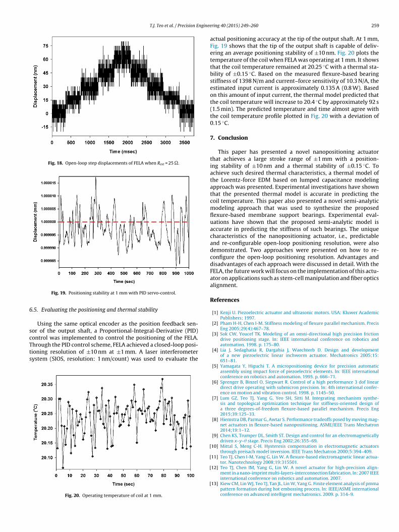
T.J. Teo et al. / Precision Enginee
Fig. 18. Open-loop step displacements of FELA when Rext = 25 �.
6
scTts
Fig. 19. Positioning stability at 1 mm with PID servo-control.
.5. Evaluating the positioning and thermal stability
Using the same optical encoder as the position feedback sen-or of the output shaft, a Proportional-Integral-Derivative (PID)ontrol was implemented to control the positioning of the FELA.
hrough the PID control scheme, FELA achieved a closed-loop posi-ioning resolution of ±10 nm at ±1 mm. A laser interferometerystem (SIOS, resolution: 1 nm/count) was used to evaluate theFig. 20. Operating temperature of coil at 1 mm.
[
[
[
[
ring 40 (2015) 249–260 259
actual positioning accuracy at the tip of the output shaft. At 1 mm,Fig. 19 shows that the tip of the output shaft is capable of deliv-ering an average positioning stability of ±10 nm. Fig. 20 plots thetemperature of the coil when FELA was operating at 1 mm. It showsthat the coil temperature remained at 20.25 ◦C with a thermal sta-bility of ±0.15 ◦C. Based on the measured flexure-based bearingstiffness of 1398 N/m and current–force sensitivity of 10.3 N/A, theestimated input current is approximately 0.135 A (0.8 W). Basedon this amount of input current, the thermal model predicted thatthe coil temperature will increase to 20.4 ◦C by approximately 92 s(1.5 min). The predicted temperature and time almost agree withthe coil temperature profile plotted in Fig. 20 with a deviation of0.15 ◦C.
7. Conclusion
This paper has presented a novel nanopositioning actuatorthat achieves a large stroke range of ±1 mm with a position-ing stability of ±10 nm and a thermal stability of ±0.15 ◦C. Toachieve such desired thermal characteristics, a thermal model ofthe Lorentz-force EDM based on lumped capacitance modelingapproach was presented. Experimental investigations have shownthat the presented thermal model is accurate in predicting thecoil temperature. This paper also presented a novel semi-analyticmodeling approach that was used to synthesize the proposedflexure-based membrane support bearings. Experimental eval-uations have shown that the proposed semi-analytic model isaccurate in predicting the stiffness of such bearings. The uniquecharacteristics of the nanopositioning actuator, i.e., predictableand re-configurable open-loop positioning resolution, were alsodemonstrated. Two approaches were presented on how to re-configure the open-loop positioning resolution. Advantages anddisadvantages of each approach were discussed in detail. With theFELA, the future work will focus on the implementation of this actu-ator on applications such as stem-cell manipulation and fiber opticsalignment.
References
[1] Kenji U. Piezoelectric actuator and ultrasonic motors. USA: Kluwer AcademicPublishers; 1997.
[2] Pham H-H, Chen I-M. Stiffness modeling of flexure parallel mechanism. PrecisEng 2005;29(4):467–78.
[3] Sok CW, Youcef TK. Modeling of an omni-directional high precision frictiondrive positioning stage. In: IEEE international conference on robotics andautomation. 1998. p. 175–80.
[4] Lia J, Sedaghatia R, Dargahia J, Waechterb D. Design and developmentof a new piezoelectric linear inchworm actuator. Mechatronics 2005;15:651–81.
[5] Yamagata Y, Higuchi T. A micropositioning device for precision automaticassembly using impact force of piezoelectric elements. In: IEEE internationalconference on robotics and automation. 1995. p. 666–71.
[6] Sprenger B, Binzel O, Siegwart R. Control of a high performance 3 dof lineardirect drive operating with submicron precision. In: 4th international confer-ence on motion and vibration control. 1998. p. 1145–50.
[7] Lum GZ, Teo TJ, Yang G, Yeo SH, Sitti M. Integrating mechanism synthe-sis and topological optimization technique for stiffness-oriented design ofa three degrees-of-freedom flexure-based parallel mechanism. Precis Eng2015;39:125–33.
[8] Hiemstra DB, Parmar G, Awtar S. Performance tradeoffs posed by moving mag-net actuators in flexure-based nanopositioning. ASME/IEEE Trans Mechatron2014;19:1–12.
[9] Chen KS, Trumper DL, Smith ST. Design and control for an electromagneticallydriven x–y–� stage. Precis Eng 2002;26:355–69.
10] Mittal S, Meng C-H. Hysteresis compensation in electromagnetic actuatorsthrough preisach model inversion. IEEE Trans Mechatron 2000;5:394–409.
11] Teo TJ, Chen I-M, Yang G, Lin W. A flexure-based electromagnetic linear actua-tor. Nanotechnology 2008;19:315501.
12] Teo TJ, Chen IM, Yang G, Lin W. A novel actuator for high-precision align-
ment in a nano-imprint multi-layers-interconnection fabrication. In: 2007 IEEEinternational conference on robotics and automation. 2007.13] Kiew CM, Lin WJ, Teo TJ, Tan JL, Lin W, Yang G. Finite element analysis of pmmapattern formation during hot embossing process. In: IEEE/ASME internationalconference on advanced intelligent mechatronics. 2009. p. 314–9.
2 nginee
[
[
[
[
[
[
[
[
60 T.J. Teo et al. / Precision E
14] Teo TJ, Kiew CM, Chen I-M, Yang G, Lin W. Model-based control of ahigh precision imprinting actuator for micro-channel fabrications. In: 2010IEEE international conference on robotics and automation. 2010. p. 3159–64.
15] Teo TJ, Yang G, Chen I-M. A large deflection and high payload flexure-basedparallel manipulator for UV nanoimprint lithography: Part I. Modeling andanalyses. Precis Eng 2014;38(4):861–71.
16] Teo TJ, Chen I-M, Yang G. A large deflection and high payload flexure-based parallel manipulator for uv nanoimprint lithography: Part II.
Stiffness modeling and performance evaluation. Precis Eng 2014;38(4):872–84.17] Hey J, Kiew CM, Yang G, Martinez-Botas R. Model-based compensation of ther-mal disturbance in a precision linear electromagnetic actuator. IEEE TransMechatron 2014;19:1477–88.
[
[
ring 40 (2015) 249–260
18] Hey J, Teo TJ, Bui VP, Yang G, Martinez-Botas R. Electromagnetic actuator designanalysis using a two stage optimization method with coarse-fine model outputspace mapping. IEEE Trans Ind Electron 2014;61:5453–64.
19] Teo TJ, Chen I-M, Yang G, Lin W. A generic approximation model for ana-lyzing large nonlinear deflection of beam-based flexure joints. Precis Eng2010;34(3):607–18.
20] BEI Kimco Magnetics linear voice coil actuators, online: BEI Kimco Magneticswebsite (February 2014).
21] H2W Technologies voice coil linear actuators, online: H2W Technologies web-
site (February 2014).22] Teo TJ, Chen I-M, Yang G, Lin W. Magnetic field modeling of a dual-magnetconfiguration. J Appl Phys 2007;102(7):074924.
23] Button BJ. Heat dissipation and power compression in loudspeakers. J AudioEng Soc 1992;40:32–41.


![IEEE/ASME TRANSACTIONS ON MECHATRONICS, VOL. 19, NO. 3 ... stage nanopositioning for high... · relies on nanopositioning is scanning probe microscopy ... [15], signal transformation](https://img.pdfslide.net/doc/110x75/5b6e5dbe7f8b9a180d8e8a82/ieeeasme-transactions-on-mechatronics-vol-19-no-3-stage-nanopositioning.jpg)