Embed Size (px)
Citation preview
A Friction Differential and Cable Transmission Design for a 3-DOFHaptic Device with Spherical Kinematics
Reuben Brewer, Adam Leeper, and J. Kenneth Salisbury
Abstract— We present a new mechanical design for a 3-DOFhaptic device with spherical kinematics (pitch, yaw, and pris-matic radial). All motors are grounded in the base to decreaseinertia and increase compactness near the user’s hand. Analuminum-aluminum friction differential allows for actuationof pitch and yaw with mechanical robustness while allowinga cable transmission to route through its center. This novelcabling system provides simple, compact, and high-performanceactuation of the radial DOF independent of motions in pitchand yaw. We show that the device’s capabilities are suitable forgeneral haptic rendering, as well as specialized applications ofspherical kinematics such as laparoscopic surgery simulation.
I. INTRODUCTION
As the application of haptics becomes more common andwidespread, a need arises for haptic device designs whichexhibit a slim form factor, are suitable over a range of scales,are mechanically robust, and are capable of general hapticrendering as opposed to specialized applications. Sphericalkinematics can be used to achieve such slim, scalable designsby concentrating the motors and transmission in the base ofthe device and leaving a slender, single-link connection to theuser’s hand. Ideally, the base of the spherical haptic devicecan be stowed outside of the user’s view, and the single linkthat connects to the user’s hand can be easily stowed, unlikea non-spherical device that connects to the user’s hand viaseveral links. While there are many different haptic deviceswith spherical kinematics, much remains to be desired interms of the simplicity, compactness, and robustness of theirmechanical design. Further, the usage of spherical kinematicshas generally been limited to haptic devices aimed at specificapplications, such as gaming and laparoscopic simulation,rather than general haptic rendering.
In this paper, we present a new mechanical design for aspherical haptic device with pitch, yaw, and radial degree-of-freedom (DOF). Our design has a compact base andslim form factor that can be scaled to large devices andsmall devices. We achieve low inertia and high compact-ness/scalability through use of grounded motors and thenovel combination of a friction differential with a new wayof routing a cable transmission through the differential toa prismatic DOF. The simplicity of our design makes thedevice easy to manufacture, assemble, and maintain, provid-ing reliable operation. The workspace and force-rendering
R. Brewer and A. Leeper are with the Department of Mechani-cal Engineering, Stanford University, Stanford, CA, USA rdbrewer,[email protected]
J.K. Salisbury is with the Departments of ComputerScience and Surgery, Stanford University, Stanford, CA, [email protected]
Fig. 1: Our 3-DOF spherical haptic device.
capabilities of our device make it suitable for general haptic-rendering, and the novel mechanical design improves onexisting designs for specific applications of spherical kine-matics, such as laparoscopic surgery simulation.
In the following sections, we begin with a discussion of re-lated work. We then describe the mechanical design, includ-ing considerations for the friction differential, the prismaticradial DOF, and the wrist gimbal. We anaylze characteristicsand capabilities of the device, including workspace, reso-lution, foward kinematics, jacobian, gravity compensation,maximum force, friction, dynamic range, and effective mass.We conclude with a discussion of future work.
II. RELATED WORK
The term “spherical kinematics” actually covers severaldistinct kinematic combinations of pitch, yaw, roll, and aprismatic, radial DOF. The simplest of such devices, such as[1] and the Impulse Engine 2000 (Immersion Corporation,San Jose, CA), are essentially 2-DOF, force-feedback joy-sticks that apply torques about pitch and yaw while keepingthe user’s hand on the surface of a fixed sphere. The SHaDehaptic device [2] has 3 DOF that apply torques in roll,pitch, and yaw centered about the user’s hand. Neither ofthese kinematic configurations allows for translation andforce-rendering in arbitrary 3D space, making these devicesunsuitable for the type of general haptic rendering possiblewith devices like the Phantom [3] or Delta [4]. The additionof a prismatic, radial DOF is critical to this general usability.
Two spherical devices that incorporate a radial DOF have
2011 IEEE/RSJ International Conference onIntelligent Robots and SystemsSeptember 25-30, 2011. San Francisco, CA, USA
978-1-61284-455-8/11/$26.00 ©2011 IEEE 2570
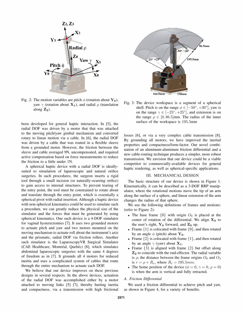
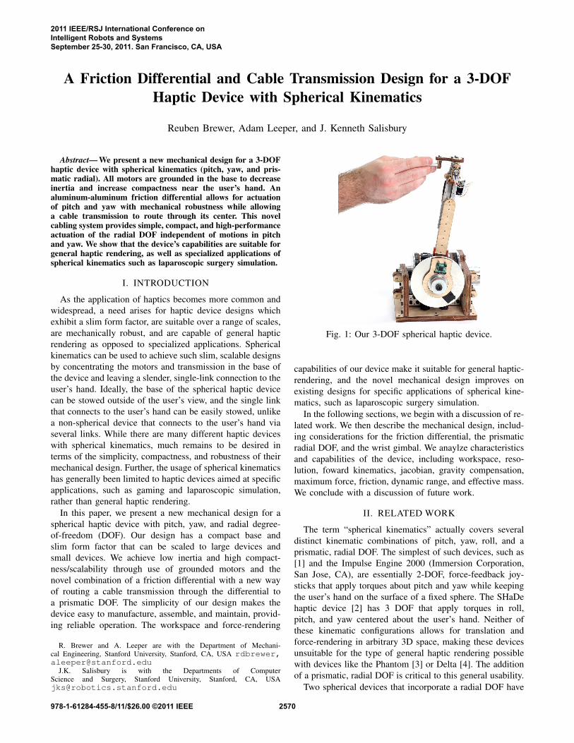
Fig. 2: The motion variables are pitch φ (rotation about Y0),yaw γ (rotation about X1), and radial ρ (translationalong Z2).
been developed for general haptic interaction. In [5], theradial DOF was driven by a motor that that was attachedto the moving pitch/yaw gimbal mechanism and convertedrotary to linear motion via a cable. In [6], the radial DOFwas driven by a cable that was routed in a flexible sleevefrom a grounded motor. However, the friction between thesleeve and cable averaged 9N, uncompensated, and requiredactive compensation based on force measurements to reducethe friction to a little under 1N.
A spherical haptic device with a radial DOF is ideally-suited to simulation of laparoscopic and natural orificesurgeries. In such procedures, the surgeon inserts a rigidtool through a small incision (or naturally-ocurring orifice)to gain access to internal structures. To prevent tearing ofthe entry point, the tool must be constrained to rotate aboutand translate through the entry point, which is essentially aspherical pivot with radial insertion. Although a haptic devicewith non-spherical kinematics could be used to simulate sucha procedure, we can greatly reduce the physical size of thesimulator and the forces that must be generated by usingspherical kinematics. One such device is a 4-DOF simulatorfor vaginal hysterectomies [7]. It uses two grounded motorsto actuate pitch and yaw and two motors mounted on themoving mechanism to actuate roll about the instrument’s axisand the prismatic, radial DOF via friction rollers. Anothersuch simulator is the LaparoscopyVR Surgical Simulator(CAE Healthcare, Montreal, Quebec) [8], which simulatesabdominal laparoscopic surgeries with the same 4 degreesof freedom as in [7]. It grounds all 4 motors for reducedinertia and uses a complicated system of cables that routethrough the entire mechanism to actuate each DOF.
We believe that our device improves on these previousdesigns in several respects. In the above devices, actuationof the radial DOF was accomplished either by a motorattached to moving links [5] [7], thereby hurting inertiaand compactness, via a transmission with high frictional
Fig. 3: The device workspace is a segment of a sphericalshell. Pitch is on the range φ ∈ [−50◦,+30◦], yaw ison the range γ ∈ [−25◦,+25◦], and extension is onthe range ρ ∈ [0, 86.5]mm. The radius of the innersurface of the workspace is 195.5mm
losses [6], or via a very complex cable transmission [8].By grounding all motors, we have improved the inertialproperties and compactness/form-factor. Our novel combi-nation of an aluminum-aluminum friction differential and anew cable-routing technique produces a simpler, more robusttransmission. We envision that our device could be a viablecompetitor to commercially-available devices for generalhaptic rendering, as well as spherical-specific applications.
III. MECHANICAL DESIGNThe basic structure of our device is shown in Figure 1.
Kinematically, it can be described as a 3-DOF RRP manip-ulator, where the rotational motions move the tip of an armalong the surface of a sphere, and linear extension of the armchanges the radius of that sphere.
We use the following definitions of frames and motions:(refer to Figure 2):
• The base frame {0} with origin O0 is placed at thecenter of rotation of the differential. We align X0 tothe user’s right, Y0 forward, and Z0 up.
• Frame {1} is colocated with frame {0}, and then rotatedby an angle φ (pitch) about Y0.
• Frame {2} is colocated with frame {1}, and then rotatedby an angle γ (yaw) about X1.
• Frame {3} is aligned with frame {2} but offset alongZ2 to coincide with the end-effector. The radial variableis ρ; the distance between the frame origins O0 and O3
is r = ρ+Re, where Re = 195.5mm.• The home position of the device (φ = 0, γ = 0, ρ = 0)
is when the arm is vertical and fully retracted.
A. Friction Differential
We used a friction differential to achieve pitch and yaw,as shown in Figure 4, for a variety of benefits.
2571
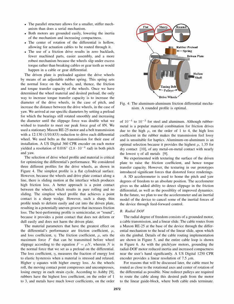
• The parallel structure allows for a smaller, stiffer mech-anism than does a serial mechanism.
• Both motors are grounded easily, lowering the inertiaof the mechanism and increasing compactness.
• The center of rotation of the differential is hollow,allowing for actuation cables to be routed through it.
• The use of a friction drive results in zero backlash,fewer machined parts, easier assembly, and a morerobust mechanism because the wheels slip under excesstorque rather than breaking cables or gear teeth as wouldhappen in a cable or gear differential.
The driven plate is preloaded against the drive wheelsby means of an adjustable rubber spring. This spring setsthe normal force on the wheels, and, thence, the frictionand torque transfer capacity of the wheels. Once we havedetermined the wheel material and desired preload, the onlyway to increase torque transfer capacity is to increase thediameter of the drive wheels, in the case of pitch, andincrease the distance between the drive wheels, in the case ofyaw. We arrived at our specific diameters by setting a preloadfor which the bearings still rotated smoothly and increasingthe diameter until the slippage force was double what wewished to transfer to meet our peak force goal of 8N. Weused a stationary Maxon RE-25 motor and a belt transmissionwith a 12:130 (1/10.833) reduction to drive each differentialwheel. We used belts as the transmission for their ease ofinstallation. A US Digital 360 CPR encoder on each motoryielded a resolution of 0.016◦ (2.8 · 10−4 rad) in both pitchand yaw.
The selection of drive wheel profile and material is criticalfor optimizing the differential’s performance. We consideredthree different profiles for the drive wheels, as shown inFigure 4. The simplest profile is a flat cylindrical surface.However, because the wheels and drive plate contact along aline, there is sliding motion at the interface which produceshigh friction loss. A better approach is a point contactbetween the wheels, which results in pure rolling and nosliding. The simplest wheel profile that achieves a pointcontact is a sharp wedge. However, such a sharp, thinprofile tends to deform easily and cut into the driven plate,resulting in a potentially uneven groove that increases frictionloss. The best-performing profile is semicircular, or “round”,because it provides a point contact that does not deform ordull easily and does not harm the driven plate.
The material parameters that have the greatest effect onthe differential’s performance are friction coefficient, µ,and loss coefficient, η. The friction coefficient, µ, sets themaximum force F that can be transmitted before wheelslippage according to the equation F = µN , wherein N isthe normal force that we set as a preload on the differential.The loss coefficient, η, measures the fraction of energy lostto elastic hysteresis when a material is stressed and relaxed.Higher η equates with higher energy loss. As the wheelsroll, the moving contact point compresses and uncompresses,losing energy in each strain cycle. According to Ashby [9],rubbers have the highest loss coefficient, on the order of 1to 3, and metals have much lower coefficients, on the order
Fig. 4: The aluminum-aluminum friction differential mecha-nism. A rounded profile is optimal.
of 10−4 to 10−3 for steel and aluminum. Although rubber-metal is a popular material combination for friction drivesdue to the high µ, on the order of 1 to 4, the high losscoefficient in the rubber makes the transmission feel lossyand is unsuitable for haptics. Aluminum-on-aluminum is anoptimal selection because it provides the highest µ, 1.35 fordry contact [10], of any metal-on-metal contact with nearlythe lowest η of all metals [9].
We experimented with texturing the surface of the drivenplate to raise the friction coefficient, and hence torquetransfer capacity. However, the texturing in our prototypesintroduced significant forces that distorted force renderings.
A 3D accelerometer is used to home the pitch and yawdegrees of freedom to an absolute position. The accelometergives us the added ability to detect slippage in the frictiondifferential, as well as the possiblity of improved dynamics.In the future, we plan to use the accelerometer and an inertialmodel of the device to cancel some of the inertial forces ofthe device through feed-forward control.
B. Radial DOF
The radial degree of freedom consists of a grounded motor,a cable transmission, and a linear slide. The cable routes froma Maxon RE-25 at the base of the device through the differ-ential mechanism to the head of the linear slide, upon whichsits the gimbal. Details of the cable routing implementationare shown in Figure 5, and the entire cable loop is shownin Figure 6. As with the pitch/yaw motors, grounding theradial-DOF motor reduced inertia and increased compactnessnear the user’s hand significantly. A US Digital 1250 CPRencoder provides a linear resolution of 7.5 µm.
For reasons that will be discussed later, the cable must berouted as close to the rotational axes and center of rotation ofthe differential as possible. Nine redirect pulleys are requiredto route the cable along this desired path from the motorto the linear guide-block, where both cable ends terminate.
2572
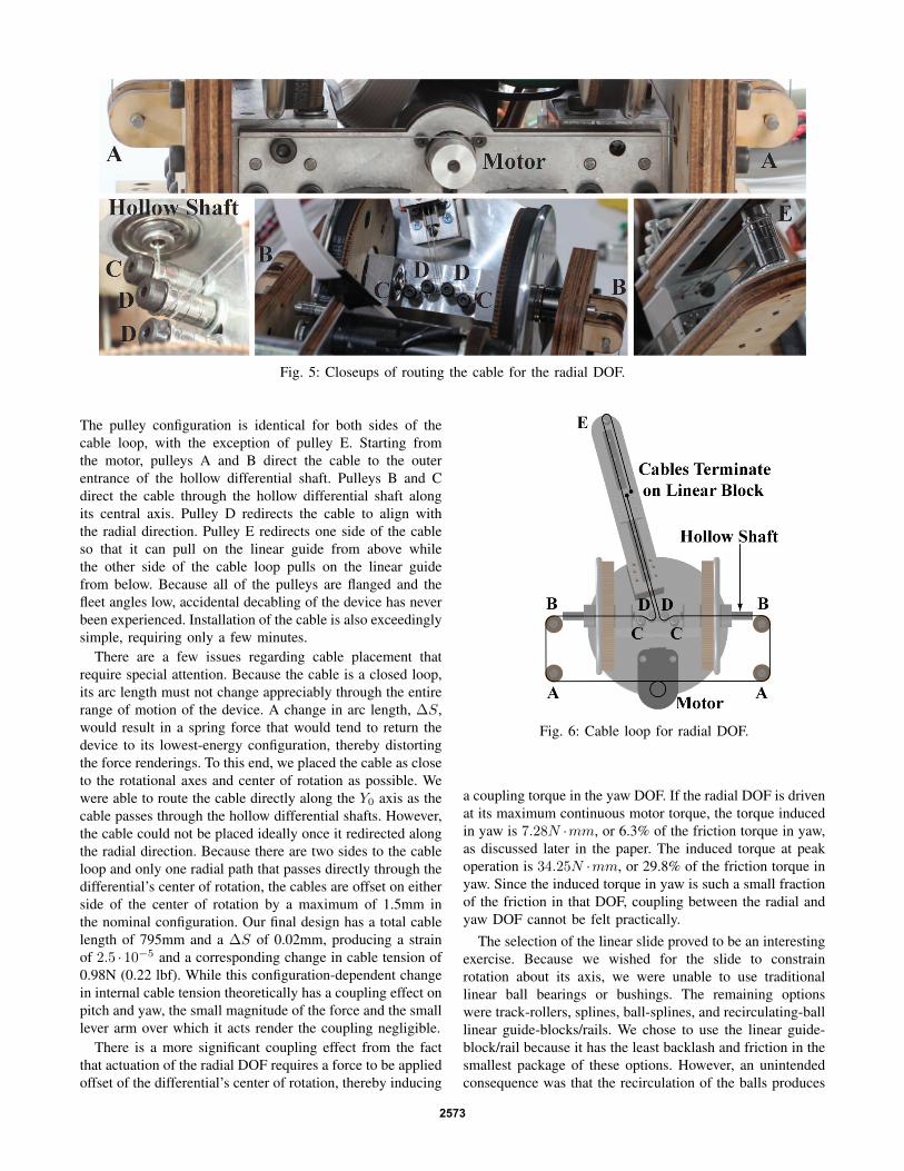
Fig. 5: Closeups of routing the cable for the radial DOF.
The pulley configuration is identical for both sides of thecable loop, with the exception of pulley E. Starting fromthe motor, pulleys A and B direct the cable to the outerentrance of the hollow differential shaft. Pulleys B and Cdirect the cable through the hollow differential shaft alongits central axis. Pulley D redirects the cable to align withthe radial direction. Pulley E redirects one side of the cableso that it can pull on the linear guide from above whilethe other side of the cable loop pulls on the linear guidefrom below. Because all of the pulleys are flanged and thefleet angles low, accidental decabling of the device has neverbeen experienced. Installation of the cable is also exceedinglysimple, requiring only a few minutes.
There are a few issues regarding cable placement thatrequire special attention. Because the cable is a closed loop,its arc length must not change appreciably through the entirerange of motion of the device. A change in arc length, ∆S,would result in a spring force that would tend to return thedevice to its lowest-energy configuration, thereby distortingthe force renderings. To this end, we placed the cable as closeto the rotational axes and center of rotation as possible. Wewere able to route the cable directly along the Y0 axis as thecable passes through the hollow differential shafts. However,the cable could not be placed ideally once it redirected alongthe radial direction. Because there are two sides to the cableloop and only one radial path that passes directly through thedifferential’s center of rotation, the cables are offset on eitherside of the center of rotation by a maximum of 1.5mm inthe nominal configuration. Our final design has a total cablelength of 795mm and a ∆S of 0.02mm, producing a strainof 2.5 ·10−5 and a corresponding change in cable tension of0.98N (0.22 lbf). While this configuration-dependent changein internal cable tension theoretically has a coupling effect onpitch and yaw, the small magnitude of the force and the smalllever arm over which it acts render the coupling negligible.
There is a more significant coupling effect from the factthat actuation of the radial DOF requires a force to be appliedoffset of the differential’s center of rotation, thereby inducing
Fig. 6: Cable loop for radial DOF.
a coupling torque in the yaw DOF. If the radial DOF is drivenat its maximum continuous motor torque, the torque inducedin yaw is 7.28N ·mm, or 6.3% of the friction torque in yaw,as discussed later in the paper. The induced torque at peakoperation is 34.25N ·mm, or 29.8% of the friction torque inyaw. Since the induced torque in yaw is such a small fractionof the friction in that DOF, coupling between the radial andyaw DOF cannot be felt practically.
The selection of the linear slide proved to be an interestingexercise. Because we wished for the slide to constrainrotation about its axis, we were unable to use traditionallinear ball bearings or bushings. The remaining optionswere track-rollers, splines, ball-splines, and recirculating-balllinear guide-blocks/rails. We chose to use the linear guide-block/rail because it has the least backlash and friction in thesmallest package of these options. However, an unintendedconsequence was that the recirculation of the balls produces
2573
a noise that increases the perception of friction in the slide.The friction properties of the device feel significantly moreisotropic when a user wears headphones than when able tohear the linear slide noise.
There are two potential drawbacks of our cable transmis-sion design for the radial DOF. One is the range-of-motionachievable in yaw. Because the two sides of the cable loopdraw nearer to each other in the same plane with increasedrotation in yaw, eventually the cables will collide. For ourfinal design, we would be able to rotate ±42◦ in yaw beforeexperiencing cable collision. For applications that requirea higher angular range-of-motion, we could eliminate thiscable collision altogether by separating the two sides of thecable loop into two different planes when they redirect tothe radial direction. This separation could be achieved byrunning the cable slightly off-axis of the hollow differentialshafts and offsetting the flanges on pulleys C and D thatredirect the cables along the radial direction.
Another potential issue is scalability. Our cable trans-mission design scales up very well but could have issuesfor very small designs (greater than a x2 size reduction).The robustness of reciprocating-ball linear guides is quitebad for the smallest of slides, requiring the use of analternative, such as a spline. Great care would be neededto minimize backlash and friction in the spline, but thisappears to be a viable option for much smaller versionsof our device. Another limiting factor could be the fatiguelife of the cable as the diameter of the redirect pulleysdecreases. Experimenting with different cable constructionsand materials could improve the fatigue life at small scales.
C. Wrist Gimbal
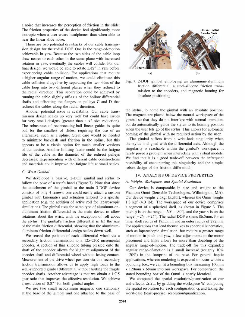
We developed a passive, 2-DOF gimbal and stylus tofollow the pose of a user’s hand (Figure 7). Note that sincethe attachment of the gimbal to the main 3-DOF deviceconsists of only 4 screws, one could easily attach a customgimbal with kinematics and actuation tailored to a specificapplication (e.g. the addition of active roll for laparoscopicsimulation). The gimbal uses the same type of aluminum-on-aluminum friction differential as the main device to allowrotations about the wrist, with the exception of roll aboutthe stylus. The gimbal’s friction differential is 1/5 the sizeof the main friction differential, showing that the aluminum-aluminum friction differential design scales down well.
We sensed the position of each differential wheel via asecondary friction transmission to a 125-CPR incrementalencoder. A section of thin silicone tubing pressed onto theshaft of the encoder allows for slight misalignment of theencoder shaft and differential wheel without losing contact.Measurement of the drive wheel position via this secondaryfriction transmission allows us to apply high loads to thewell-supported gimbal differential without hurting the fragileencoder shafts. Another advantage is that we obtain a 1:7.5gear ratio that improves the effective resolution. We achievea resolution of 0.07◦ for both gimbal angles.
We use two small neodymium magnets, one stationaryat the base of the gimbal and one attached to the base of
(a) (b)
Fig. 7: 2-DOF gimbal employing an aluminum-aluminumfriction differential, a steel-silicone friction trans-mission to the encoders, and magnetic homing forabsolute positioning
the stylus, to home the gimbal with an absolute position.The magnets are placed below the natural workspace of thegimbal so that they do not interfere with normal operation,but do automatically guide the stylus to its homing positionwhen the user lets go of the stylus. This allows for automatichoming of the gimbal with no required action by the user.
The gimbal suffers from a wrist-lock singularity whenthe stylus is aligned with the differential axis. Although thesingularity is reachable within the gimbal’s workspace, itrarely posed a problem when interacting with virtual models.We find that it is a good trade-off between the infrequentpossibility of encountering this singularity and the simple,robust design of the friction differential.
IV. ANALYSIS OF DEVICE PROPERTIES
A. Weight, Workspace, and Spatial Resolution
Our device is comparable in size and weight to thePhantom Omni (Sensable Technologies, Willmington, MA).Our device weighs 2.5kgf (5.5lbf), whereas the Omni weighs1.8 kgf (4.0 lbf). The workspace of our device comprisesa segment of a spherical shell, as shown in Figure 3. Thepitch φ is on the range [−50◦,+30◦], and the yaw γ is on therange [−25◦,+25◦]. The radial DOF ρ spans 86.5mm, for aninner shell radius of 195.5mm and an outer radius of 282mm.For applications that lend themselves to spherical kinematics,such as laparoscopic simulation, but require a greater rangeof motion in pitch and yaw, a few adjustments to the motorplacement and links allows for more than doubling of theangular range-of-motion. The trade-off for this expandedangular range-of-motion is a small increase (roughly 10%- 20%) in the footprint of the base. For general hapticapplications, wherein rendering is expected to occur within abounding box, we can fit a bounding box measuring 160mmx 120mm x 68mm into our workspace. For comparison, thestated bounding box of the Omni is nearly identical.
We computed the spatial resolution/quantization at ourend-effector ∆Xee by gridding the workspace W, computingthe spatial resolution for each configuration q, and taking theworst-case (least-precise) resolution/quantization.
2574
∆Xee = maxq∈W
{||J(q)δqmin ||}, δqmin =
2.8 · 10−4
2.8 · 10−4
7.5 · 10−3
(1)
where δqminis the vector of joint resolutions set by our
encoders’ precision. We obtained a worst-case resolutionof 0.112mm across the entire workspace. The resolution islinearly dependent upon ρ, but is almost constant across pitchand yaw (0.1098 ± 0.0016mm across all pitch, yaw for ρ= max extension). For comparison, the Sensable PhantomOmni is somewhat more precise than our device, with a best-case spatial resolution of 0.055mm, or 49% of our resolution.
B. Forward Kinematics
The transformation between motor angles/torques andpitch, yaw angles/torques on the differential plate is:
φ =(θmotor1 + θmotor0)
2N, γ =
(θmotor1 − θmotor0)
2N
d
D(2)
τφ = N(τmotor1 + τmotor0), τγ = N(τmotor1 − τmotor0)D
d(3)
τmotor0 =1
2N(τφ − τγ
d
D), τmotor1 =
1
2N(τφ + τγ
d
D) (4)
where dD is the ratio between drive wheels diameter d and
distance between the drive wheels D, and N is the gear ratiobetween the motors and differential drive wheels. In our case,dD = 1, and N is 10.83.
The forward kinematic transformation from the end effec-tor frame to the world frame is
0T 3 =
Cφ SφSγ SφCγ (ρ+Re)SφCγ0 Cγ −Sγ −(ρ+Re)Sγ−Sφ CφSγ CφCγ (ρ+Re)CφCγ
0 0 0 1
(5)
C. Jacobian and SingularitiesThe Jacobian for linear motions at the end-effector is
0Jv =
(ρ+Re)CφCγ −(ρ+Re)SφSγ SφCγ0 −(ρ+Re)Cγ −Sγ
−(ρ+Re)SφCγ −(ρ+Re)CφSγ CφCγ
(6)
A singularity exists when γ = ±π2 , but these configura-tions are outside of the device’s workspace.
D. Gravity Compensation
We use active, feed-forward gravity compensation so thatthe device floats in all configurations without being a burdenon the user’s hand. The 3D CAD model provides an accuratemass model of the device. The joint-space gravity torquevector 0τg is:
0τg =
τφτγFρ
= g
−m1X1Cφ −m2(X2Cφ + Z2CγSφ) −m3(ρ+ RC)CγSφCφSγ(−m2Z2 −m3(ρ+ RC))
m3CφCγ
(7)
where m1 = 0.13kg, m2 = 0.33kg, m3 = 0.08kg, X1 =11.23mm, X2 = 41.69mm, Z2 = 20.51mm, and RC =132.48mm.
E. Maximum Isotropic Force
A practical metric for evaluating the force capabilitiesof our device is the maximum isotropic force over theworkspace, or the largest force that can be exerted in alldirections and kinematic configurations before any motorssaturate. For a configuration, we find the minimum forcemagnitude fu that will saturate any of the motors acrossall directions U. The torque vector τ that will result in thelargest force FMax Iso before any of the motors saturate is:
τ = arg minU∈<{max(τi/τSAT i) | fuU = J τ}, FMax Iso = J τ (8)
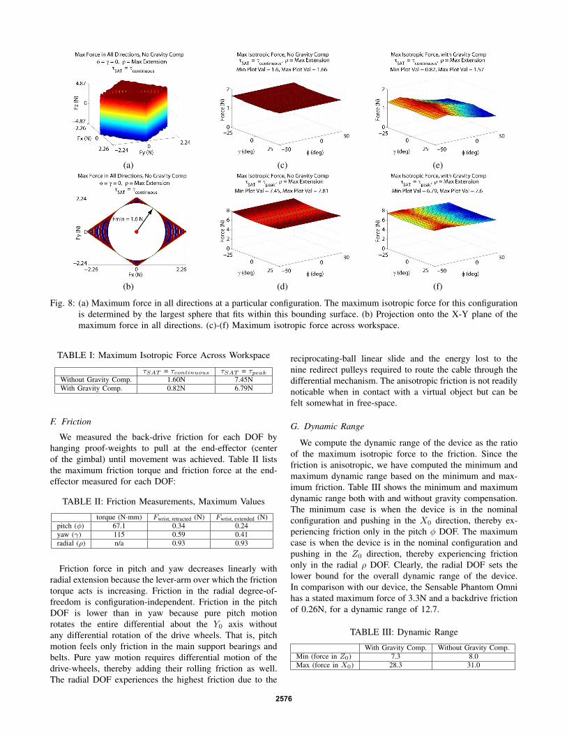
where τSAT i is the saturation torque for each motor, in-dexing on i. We solved for FMax Iso computationally bygridding the workspace with finite configurations, griddingforce directions at each configuration, and incrementallyincreasing the force magnitude fu until one of the motorssaturates for a given configuration and force direction U.Figures 8(a)-(b) show the maximum force in all directions foran example configuration. Despite the rough appearance dueto sampling, the surface has 6 sides corresponding to the theforward and reverse saturation of each motor. Figures 8(c)-(f) show the maximum isotropic force at each configurationacross the workspace. Without gravity compensation, themaximum force is roughly constant across all φ, γ anddecreases linearly with increasing ρ. The use of active gravitycompensation decreases the maximum isotropic force be-cause some of the rendering force is used to counter gravity.Gravity compensation also makes the maximum isotropicforce significantly more configuration-dependent, with thehighest available forces corresponding to low values of yawand negative values of pitch.
Table I lists the maximum isotropic force that the devicecan exert across its workspace (the minimum value shown inFigures 8(c)-(f)). The values are tabulated for combinationswith and without gravity compensation, as well as motorsaturation at τcontinuous (maximum continuous torque) andτpeak (intermittent, peak torque). Note that the stated max-imum continuous force for the Sensable Phantom Omni is0.88 N, a value which is only 7% higher than our maximumcontinuous isotropic force with gravity compensation (ourworst case). Since the Omni is typically used without gravitycompensation, by practical comparison, our device is able toproduce 82% higher maximum continuous force.
Peak forces can be achieved by overdriving the motorsintermittently, according to the manufacturer’s thermal spec-ifications. For example, the motors could be run at 100%τpeak (4.7 x τcontinuous) for durations of up to 0.48S witha 5.2% duty cycle or at 50% τpeak (2.6 x τcontinuous) fordurations of up to 2.09S with a duty cycle of 53.5%.
2575
(a) (c) (e)
(b) (d) (f)
Fig. 8: (a) Maximum force in all directions at a particular configuration. The maximum isotropic force for this configurationis determined by the largest sphere that fits within this bounding surface. (b) Projection onto the X-Y plane of themaximum force in all directions. (c)-(f) Maximum isotropic force across workspace.
TABLE I: Maximum Isotropic Force Across Workspace
τSAT = τcontinuous τSAT = τpeakWithout Gravity Comp. 1.60N 7.45NWith Gravity Comp. 0.82N 6.79N
F. Friction
We measured the back-drive friction for each DOF byhanging proof-weights to pull at the end-effector (centerof the gimbal) until movement was achieved. Table II liststhe maximum friction torque and friction force at the end-effector measured for each DOF:
TABLE II: Friction Measurements, Maximum Values
torque (N·mm) Fwrist, retracted (N) Fwrist, extended (N)pitch (φ) 67.1 0.34 0.24yaw (γ) 115 0.59 0.41radial (ρ) n/a 0.93 0.93
Friction force in pitch and yaw decreases linearly withradial extension because the lever-arm over which the frictiontorque acts is increasing. Friction in the radial degree-of-freedom is configuration-independent. Friction in the pitchDOF is lower than in yaw because pure pitch motionrotates the entire differential about the Y0 axis withoutany differential rotation of the drive wheels. That is, pitchmotion feels only friction in the main support bearings andbelts. Pure yaw motion requires differential motion of thedrive-wheels, thereby adding their rolling friction as well.The radial DOF experiences the highest friction due to the
reciprocating-ball linear slide and the energy lost to thenine redirect pulleys required to route the cable through thedifferential mechanism. The anisotropic friction is not readilynoticable when in contact with a virtual object but can befelt somewhat in free-space.
G. Dynamic Range
We compute the dynamic range of the device as the ratioof the maximum isotropic force to the friction. Since thefriction is anisotropic, we have computed the minimum andmaximum dynamic range based on the minimum and max-imum friction. Table III shows the minimum and maximumdynamic range both with and without gravity compensation.The minimum case is when the device is in the nominalconfiguration and pushing in the X0 direction, thereby ex-periencing friction only in the pitch φ DOF. The maximumcase is when the device is in the nominal configuration andpushing in the Z0 direction, thereby experiencing frictiononly in the radial ρ DOF. Clearly, the radial DOF sets thelower bound for the overall dynamic range of the device.In comparison with our device, the Sensable Phantom Omnihas a stated maximum force of 3.3N and a backdrive frictionof 0.26N, for a dynamic range of 12.7.
TABLE III: Dynamic Range
With Gravity Comp. Without Gravity Comp.Min (force in Z0) 7.3 8.0Max (force in X0) 28.3 31.0
2576
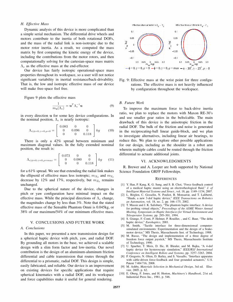
H. Effective MassDynamic analysis of this device is more complicated than
a simple serial mechanism. The differential drive wheels andmotors contribute to the inertia of both rotational DOFs,and the mass of the radial link is non-isotropic due to themotor rotor inertia. As a result, we computed the massmatrix by first computing the kinetic energy of the device,including the contributions from the motor rotors, and thencomputationally solving for the cartesian-space mass matrixΛe as the effective mass at the end-effector.
Our device has fairly isotropic operational-space massproperties throughout its workspace, so a user will not noticesignificant variability in inertial resistance/back-drivability.That is, the low and isotropic effective mass of our devicewill make free-space feel free.
Figure 9 plots the effective mass
1
mu(Λe)= uTΛ−1
e u (9)
in every direction u for some key device configurations. Inthe nominal position, Λe is nearly isotropic:
Λe|φ=0,γ=0,ρ=0 =
0.083 0 00 0.096 00 0 0.118
kg (10)
There is only a 42% spread between minimum andmaximum diagonal values. In the fully extended nominalposition, the result is:
Λe|φ=0,γ=0,ρ=max =
0.073 0 00 0.080 00 0 0.118
kg (11)
for a 61% spread. We see that extending the radial link makesthe ellipsoid of effective mass less isotropic; mX0
and mY0
decrease by 12% and 17%, respectively, but mZ0remains
unchanged.Due to the spherical nature of the device, changes in
pitch or yaw configuration have minimal impact on theeffective mass. While the principal directions of Λe change,the magnitudes change by less than 3%. Note that the statedeffective mass of the Sensable Phantom Omni is 0.045kg, or38% of our maximum/54% of our minimum effective mass.
V. CONCLUSIONS AND FUTURE WORKA. Conclusions
In this paper, we presented a new transmission design fora spherical haptic device with pitch, yaw, and radial DOF.By grounding all motors in the base, we achieved a scalabledesign with a slim form factor and low-inertia. Our novelcontribution is the design of an aluminum-aluminum frictiondifferential and cable transmission that routes through thedifferential to a prismatic, radial DOF. This design is simple,easily fabricated, and reliable. Our device is an improvementon existing devices for specific applications that requirespherical kinematics with a radial DOF, and its workspaceand force capabilities make it useful for general rendering.
Fig. 9: Effective mass at the wrist point for three configu-rations. The effective mass is not heavily influencedby configuration throughout the workspace.
B. Future Work
To improve the maximum force to back-drive inertiaratio, we plan to replace the motors with Maxon RE-30’sand use smaller gear ratios in the belts/cable. The maindrawback of this device is the anisotropic friction in theradial DOF. The bulk of the friction and noise is generatedin the reciprocating-ball linear guide-block, and we planto investigate alternatives, including linear air bearings, toreduce this. We plan to explore other possible applicationsfor our design, including as the shoulder in a robot armwherein multiple cables could be routed through the frictiondifferential to actuate additional joints.
VI. ACKNOWLEDGMENTS
R. Brewer and A. Leeper are both supported by NationalScience Foundation GRFP Fellowships.
REFERENCES
[1] Y. Han, P. Kang, K. G. Sung, and S. B. Choi, “Force feedback controlof a medical haptic master using an electrorheological fluid,” J. ofIntelligent Material Systems and Struct., vol. 18, pp. 1149–1154, 2007.
[2] L. Birglen, C. Gosselin, N. Pouliot, B. Monsarrat, and T. Laliberte,“Shade, a new 3-dof haptic device,” IEEE Transactions on Roboticsan Automation, vol. 18, no. 2, pp. 166–175, 2002.
[3] T. Massie and J. K. Salisbury, “The phantom haptic interface: A devicefor probing virtual objects,” Proceedings of the ASME Winter AnnualMeeting, Symposium on Haptic Interfaces for Virtual Environment andTeleoperator Systems, pp. 295–301, 1994.
[4] S. Grange, F. Conti, P. Helmer, P. Rouiller, , and C. Baur, “The deltahaptic device,” Eurohaptics, 2001.
[5] M. Smith, “Tactile interface for three-dimensionsal computer-simulated environments: Experimentation and the design of a brake-motor device,” MS Thesis, Massachusetts Inst. of Technology, 1988.
[6] M. Russo, “The design and implementation of a three degree offreedom force output joystick,” MS Thesis, Massachusetts Instituteof Technology, 1990.
[7] U. Spaelter, T. Moix, D. Ilic, H. Bleuler, and M. Bajka, “A 4-dofhaptic device for hysteroscopy simulation,” IEEE/RSJ InternationalConference on Intelligent Robots and Systems, pp. 3257–3263, 2004.
[8] P. Gregorio, N. Olien, D. Bailey, and S. Vassallo, “Interface apparatuswith cable-driven force-feedback and four grounded actuators,” U.S.Patent 7 404 716, 2008.
[9] M. Ashby, Materials Selection in Mechanical Design, 3rd ed. Else-vier, 2005, p. 62.
[10] E. Oberg, F. Jones, and H. Horton, Machinery’s Handbook, 21st ed.Industirial Press Inc., 1981, p. 546.
2577