Embed Size (px)
Citation preview

Network Protocols and Algorithms ISSN 1943-3581
2010, Vol. 2, No. 4
www.macrothink.org/npa 61
A Fuzzy Logic Approach for Reducing Handover Latency in Wireless Networks
Ali Safa Sadiq, Kamalrulnizam Abu Bakar, and Kayhan Zrar Ghafoor
Faculty of Computer Science & Information Systems
Universiti Teknologi Malaysia, 81310 UTM Skudai, Johor D. T, Malaysia
Tel: 006-012-7765891 E-mail: [email protected]
Received: December 9, 2010 Accepted: December 30, 2010 DOI: 10.5296/npa.v2i4.527
Abstract
Existing wireless networks aim to provide information communication services between mobile nodes. When a mobile node MN moves between different radio networks, a handover process is needed to change its point of attachment to the predicted radio network. Since traditional (based on one metric Received Signal Strength Indicator) predictions of handover decisions do not perform well, it is imperative that we develop an intelligent approach to facilitate the handover prediction process, thus yielding seamless handovers. In this article, a Fuzzy logic-based Hand-off Decision (FHD) approach is proposed for wireless networks. The parameters include a Received Signal Strength Indicator and the relative direction of a Mobile Node toward an access point, which are considered as inputs to the fuzzy logic system in order to facilitate the handover decision process and chose the best preferable access point around this MN. This fuzzy logic system impacted positively on handover decision making. Moreover, in terms of obtain the most accurate Access Point AP between certain number of APs in the range of MN’s roaming. Finally, in order to achieve a fair comparison with a standard handover procedure in Fast Mobile IPv6 and RSSI threshold approach as well, we have implemented a fuzzy logic-based hand-off decision approach in Omnet++. Our simulation results show that the proposed approach is able to reduce the handover latency. The results show that by using the proposed method, the performance improved significantly by decrease the wireless access media delay (link-layer) which basically occur during link switching.
Keywords: Fuzzy Logic, Wireless LAN, Handover Decision, Handover Signalling.

Network Protocols and Algorithms ISSN 1943-3581
2010, Vol. 2, No. 4
www.macrothink.org/npa 62
1. Introduction
The huge development in wireless technologies has increased aggregate mobility. The Mobile IP (MIP) provides mobile users with mobility while they alter their point of attachment during the handover process, which occurs between the current wireless access network and the new access network. This mobility is handled by a network layer (Layer 3) via Mobile IP extensions; hence, mobile connectivity can be live while a Mobile Node (MN) is roaming between different access networks.
However, still have many technical weaknesses for wireless networks, including high handover latency and packet loss. These kinds of limitations influence the wireless network’s functionality, and particularly influence the applications that are processed over these networks, like real-time applications, such as Voice over IP (VoIP) or video streaming.
Therefore, there are many protocols, which have been designed to achieve an uninterrupted linkage. Mobile IPv6 is one of the latest versions, which has been introduced by the Internet Engineering Task Force (IETF) to maintain mobility in wireless networks [1]. This protocol is responsible for processing the network layer (L3) handover between a MN and Access Routers (AR). Throughout this protocol, a MN provides internet connectivity while its Access Point (AP) changes from one AR to another. During this handover process, time is taken while a data-link switching process take place between the current AP and the new AP. This switching process is called the Layer 2 (L2) handover procedure, which is executed after the handover decision has been taken. The MN in this handover time won’t be able to send or receive any packets. Therefore, time is required to complete this process, which can trigger some drawbacks, such as an increase in handover latency and packet loss. In this context, a need to develop a method to achieve good mobility management has become imperative.
Generally, a mobility management system includes two essential elements: a handover-decision management phase and a handover execution phase. These two phases are supposed to be executed in a short time to allow the MN to be reached on any AP that might it wants to move during the roaming [2]. Therefore, the IEIF has developed another mobility protocol extension to manage the handover process, which is called Fast Mobile IPv6 [3]. FMIPv6 is one of the IPv6 extensions, which tackles mobility management in wireless networks. FMIPv6 has two modes of operation to perform during the handover: the proactive and reactive modes [4]. In the proactive mode, the fast handover would be able to perform several signals (triggers) during the L2 (link-layer) handover prior to L3 between the current and potential router while it is still connecting with the current AP. Under this proactive mode, two variations occur: hard proactive (HP) and soft proactive (SP) [4], [5]. A MN can execute the SP mode in case there is one or more AP, which has a better signal from the current point of attachment. Unfortunately, this protocol also has some weaknesses in the handover process [4]
Basically, a MN cannot know what the potential handover will be during its roaming period without having a good quality intelligence system. There are some parameters that

Network Protocols and Algorithms ISSN 1943-3581
2010, Vol. 2, No. 4
www.macrothink.org/npa 63
can provide a timely and correct handover decision while the MN is still connected to the current AP.
The horizontal handover process (within this paper’s scope) starts when the link quality parameters decrease, for example, the Received Signal Strength Indicator (RSSI), Signal-to-noise ratio (SNR), Data rate ratio, and so on. Based on the range of these variables, a MN will build its own handover decision, which identifies when an AP must be activated. For this handover decision to take place, a MN normally depends on one parameter, which is generated from the network environment. For example, in IEEE 802.11b networks, the link quality is measured by the value of the RSSI. The reliance on RSSI value only in handover decision will causes unstable link. That’s occurs when MN obtain a handover decision with one particular AP within good RSSI value but, in fact the MN doesn’t have a good relative direction toward that AP. From this point we can observe clearly that the reliance on the RSSI alone to make the handover decision is not worthy at all. Moreover, this unreliable handover decision will increase the number of handovers before MN achieves a stable link of attachment with qualified AP. Therefore, we need to achieve a robust handover decision making mechanism in order to obtain the most accurate handover decision.
In this paper, we propose a fuzzy logic-based hand-off decision (FHD) approach to achieve the correct handover decision in wireless networks. The RSSI and Relative Direction of the MN toward the AP are considered as input parameters in our fuzzy logic system. The output of this fuzzy system is the quality cost of each AP in the range. Using this technique, a MN can track the correct handover decision in advance before reaching the link-down time, which causes high handover latency which requires building new data-link connection. Thus, MN can obtain its own decision in advance which leads that to decrease the overall handover latency.
2. Related Work
There are many studies, which have examined handover latency in Wireless Local Area Networks (WLAN). In IEEE 802.11b which uses signaling process for traffic control between AP and MN. This process contains sequence phases, like probe requests and probe responses, authentication requests and authentication responses, and finally, reassociation requests and reassociation responses. These sequences are distributed as three Layer2 phases: potential phase, probe or scanning phase, and authentication phase.
In the potential phase, a MN senses if the current link quality is weakening when some frames fail to be transferred via the network. At the same time, a MN receives other signals, which belong to other, better quality APs in the range. While in the probe or scanning phase, a MN starts to collect the RSSI values for the APs that are available in the range and then makes decisions about the handover. The handover decision depends on the RSSI value, which determines the quality of the current link and the desirable link. Afterwards, the authentication phase is applied between the MN and the new AP; this happens when the authentication is enabled in the APs. Figure 1 shows these three link-

Network Protocols and Algorithms ISSN 1943-3581
2010, Vol. 2, No. 4
www.macrothink.org/npa 64
layer phases.
Figure 1. Link-layer IEEE 802.11/b Handover Procedure
In each active scan executed by the MN, the worst possible delay is 300-400 ms [6]. This delay period is taken every time the MN needs to obtain a list of APs in the range in order to make the handover decision. When the MN decides to make the handover on one unqualified AP, soon afterwards it will need to perform another handover process, which will cause a high handover latency. Thus, many researchers have tried to decrease this latency and identify a more effective way to reduce the overall latency so as not to degrade the quality of service (QoS), especially with real-time applications.
In [7], the authors proposed using the neighbourhood graph (NG) method to help define the APs in the range, which would then support the handover process by selecting an appropriate AP. Other authors [8] used calculating optimals, like MaxChannelTime, MinChannelTime and beacon interval.
Fixing the search operation to a number of APs on a given channel has also been proposed by another study [9] , which aimed to reduce scanning time then decrease the handover latency by using an intelligent channel scan in IEEE 802.11 WLANs. In [10] and [11] , respectively, the scanning phase was bypassed to reduce the Media Access Control MAC layer handover, and a location-based technique was used to minimize the handover latency.
In general, the handover process starts when the MN begins to lose a connection with the current associated AP. At the same time, it stops receiving the traffic of packets, which are forwarded by the Corresponded Node (CN) over several seconds. During this

Network Protocols and Algorithms ISSN 1943-3581
2010, Vol. 2, No. 4
www.macrothink.org/npa 65
disconnected period, the MN is processing the handover procedure. The handover procedure in IEEE 802.11 has two stages: discovery of the available APs by using passive or active scanning, re-association, and the re-authentication stage. These stages are handled by L2 then depend on this process MN will decides whether handle L3 (network-layer) process handover procedure or no. This happening when MN obtains a handover decision on AP belong to different subnet. The time which take for L2 handover process is known as the access media delay.
In [12], the authors mention that main delay in L2 is caused by the scanning phase, while the authentication has a constant delay. Therefore, the scanning decreases when the MN achieves the most appropriate AP during the handover process. This will depend on the handover decision after the scanning phase. The RSSI quality is discussed in [13], but the maintainability of predicting the future RSSI is not covered by this study. In [13], an analysis study was done to show the effectiveness of Layer 2 (link-layer) and Layer 3 (network-layer) parameters, in terms of performance of mobility management, which then aim to reduce handover latency. However, the idea of using L2 triggering to help the handover decision is not covered by this analysis.
In [14] the authors discussed a handover decision making mechanism which depends on RSSI. MN here doesn’t perform the handover while the current AP’s RSSI value is less then candidates (APs). The threshold of RSSI value must be identified in order to handle the comparison between the current AP and the others with this threshold. From this study we will be able to reduce the ping-pong effect but at the same time will affect negatively the handover latency [15].
Therefore, the reliance on RSSI alone in handover decision making is not reliable and will cause drawbacks such as ping-pong effectiveness [16]. This occurs when the handover execute many times between new AP and the current one which happing due to the fluctuation over the handover threshold.
Our aim is to use the L2 parameters, which are RSSI and relative direction of the MN towards the AP to support the MN to make the correct handover decision. The idea of using the relative direction between the MN and each AP is the novel idea which helps to obtain accurate handover decisions in collaboration with the RSSI. Throughout this collaboration MN won’t obtain the handover decision on AP with good RSSI value and at the same time it’s not on the same direction. These two parameters used in our FHD approach (in a similar way to the two inputs for the fuzzy-logic system) will be fuzzified then defuzzified; the output will be the quality cost for each AP in the range of the MN.
3. Proposed Algorithm
The proposed FDH in this paper used a fuzzy logic system to obtain the quality cost for each AP. A fuzzy logic system helps to decide which AP is chosen as the next new link of attachment for the MN during its roaming. Fuzzy inference systems have been successfully applied in fields such as automatic control, data classification, decision

Network Protocols and Algorithms ISSN 1943-3581
2010, Vol. 2, No. 4
www.macrothink.org/npa 66
analysis, expert systems, and computer vision. There are two crisp input values for the fuzzy logic system in our study (the RSSI’s and the MN’s relative direction towards each AP). Through these two values the fuzzy Inference system provides the quality cost for each AP in the range of MN. This will support the MN in handover decision making to choose the AP with good RSSI and more directed.
These crisp values will change to fuzzy values by selecting the membership function for each. In the two sections below, we will discuss the two values, which have been selected in our fuzzy logic system.
3.1 Tracking the RSSI
The Received Signal Strength Indicator (RSSI) is one of the most common L2 parameters used in handover decision making [15]. Through RSSI monitoring, which is handled by the MN, we can analyses from collected RSSI values, the quality and the distance for each AP in the range. For example, when the MN moves away from one AP, the RSSI for that AP gradually reduces, i.e., the quality of the AP decreases.
Therefore, we need to know the range of the RSSI in IEEE 802.11 WLANs (maximum to minimum value) to help identify the membership function for this input parameter in our fuzzy-logic system. The RSSI in this study has been tracked by using the real-test bed measurement. We used a scenario whereby one laptop (as a MN) moved in an area containing several APs in the range of movement. The MN moved at human speed (1 metre/second). Using this scenario, we could determine the signal strength for scanning APs. The second reason for using this real-test bed was to determine the optimal RSSI threshold value, after which the MN must start the handover procedure. While the MN was moved around, we used some real-time applications on the laptop, such as VoIP, Video streaming, and other internet applications. Throughout this experiment, we identified the RSSI value in which the running application attained the worst quality. From this value, we selected the threshold value, which was used as our handover threshold value. The real-test bed for the RSSI measurement was done by using “inSSIDer” software to track the RSSI for the available APs.
Figure 2 shows the RSSI value for APs in the range while the MN is moving across some APs. The blue curve represents an AP in the range of the movement. This curve shows the MN when it has started its movement; the received signal was -28 dbm for this particular AP. During the movement period (in minutes), after the MN moved 1 minute (m), the RSSI for this AP started to increase to -21 dbm. This means the distance between the MN and AP1 was very close. After 4 m, the RSSI curve started to go down, which means the MN started to move away from the AP. After minute 7.5, the RSSI curve declined sharply to below -70 dbm. The last RSSI value obtained after minute 7 was tested in terms of quality of signal strength, using some real-time applications, like video streaming, chatting, and other online applications. We observed that the RSSI value, when below -65 dbm did not support these kinds of applications. Therefore, the threshold for RSSI in this study was selected to be -60 dbm. This threshold is a suitable value to maintain a quality of service. These values were collected for RSSI in order to help define

Network Protocols and Algorithms ISSN 1943-3581
2010, Vol. 2, No. 4
www.macrothink.org/npa 67
RSSI membership functions in our fuzzy logic system.
Figure 2. RSSI Tracking while MNs are Roaming
3.2 Tracking Direction
Direction is the second metric, which was used in our proposed fuzzy logic system. Generally, when the MN starts roaming across different APs it might identify more than one AP with a good quality RSSI. However, one of these APs may not be situated in the same direction as the MN, so the MN may not move towards this particular AP. This demonstrates that the MN can obtain the wrong handover decision if the AP is not in the same trajectory. This can occur when MN uses the RSSI value only to obtain the handover decision.
During this process, the MN might start the handover procedure with one AP with a high RSSI even though it wasn’t in a relative direction. However, if the MN obtains an AP in the same direction, the handover decision will be more appropriate. Figure 3 shows the relationship between direction and handover decision.
Figure 3. MN Moving in a Linear Direction and Crossing Three APs
Network Protocols and Algorithms ISSN 1943-3581
2010, Vol. 2, No. 4
www.macrothink.org/npa 68
Figure 3 shows a scenario where there are three APs in the range. Two belong to the Home Agent and the third one belongs to the Foreign Agent. Each AP has a fixed position, which is generated by the X-axis and Y-axis. During the MN’s linear movement, the X-axis is always shifting, while the Y-axis is fixed to the value of 10.
Formula (1) was used to calculate the angle of direction for each AP from the MN’s current position during its movement. Suppose that the direction of the MN is (MdX1, MdY1), the position of AP is (PaX2, PaY2); Mdx and Mdy represent the direction of the MN, with the X-axis and Y-axis, Pax and Pay Position of each AP, also with the X-axis and Y-axis. Formula (1) describes how we can compute the angle.
a arccosMdX1. PaX2 MdY1. PaY2
√Mdx1 MdY1 . √PaX2 PaY2 1
If the MN wants to make a handover decision for any AP in the range, it must initiate the handover process. Formula (1) can be used to calculate the angle between the MN and the desirable AP. This calculation is based on the X-axis and Y-axis for the MN and the AP on the geographical map, using Global Positioning System (GPS) technology.
The MN is equipped with the GPS to obtain the updated X- and Y- axis with every movement. The AP’s location is defined in advance, which considered as a fixed position. Once all positions for the APs are collected through GPS’ map, the MN will save the coordinate of these APs inside its own Basic Service Set ID BSSID. Thus, when MN goes through the network, the updated GPS map will download automatically from the server with X-axis and Y-axis for all APs in the range and its own current position as well. Throughout this process, the MN knows its own position and knows the APs in the range, which enables to calculate the direction angle between MN’s current position and each AP.
Frequently, the MN calculates and checks the angle between itself and the desired AP. If this angle is less than 37.7 degree, it means the MN is in the same direction as that particular AP.
After we applied Formula (1) in the scenario (Figure 3), we collected the curves of variation in angles between the MN and each AP during the MN’s movement. In Figures 4, 5, and 6, we show graphs of variation in angle of direction between the MN and each of the three APs in our Figure 3 scenario. The X-axis in Figure 3 is from 0 to 50, which refers to the distance on the ground (50 m). Figure 4 demonstrates that during its first movement, the MN was extremely close to AP1, with a 10-degree angle. After 5 m, the degree of the angle has inclined sharply because the MN started moving away from AP1. At the same time, the MN moved into a related direction with AP2. Hence, we can observe that from the curves of direction angle for AP2 and AP3 in figures 5 and 6 respectively, they are increasing while MN is moving directly towards them.

Network Protocols and Algorithms ISSN 1943-3581
2010, Vol. 2, No. 4
www.macrothink.org/npa 69
Figure 4. The Variation in Angle of Direction between MN and AP1
Figure 5. The Variation in Angle of Direction between MN and AP2
0 5 10 15 20 25 30 35 40 450
10
20
30
40
50
60
70
X-axis
The
Ang
le D
egre
es
The angle of direction degrees between MN and AP1 during linear movement
0 5 10 15 20 25 30 35 40 450
5
10
15
20
25
30
35
40
45
X-axis
The
angl
e de
gree
s
The angle of direction degrees between MN and AP2 during linear movement

Network Protocols and Algorithms ISSN 1943-3581
2010, Vol. 2, No. 4
www.macrothink.org/npa 70
Figure 6. The Variation in Angle of Direction between MN and AP3
In addition, the RSSI measurements, which were obtained by the MN for the three APs during the movement period, show that at 7 seconds, the RSSI for AP3 is -75 but afterwards, it starts to increase. We can analyse from this that while the MN is still connecting with AP1 or AP2, the RSSI for its current link goes down. For AP3, after 7 seconds, it starts to increase.
Therefore, we can conclude that by using the RSSI threshold value in handover decisions, the MN will still keep connecting with the current AP until the threshold is reached. It is a well-known fact that this will affect the total handover latency, which will increase. On the other hand, when the MN uses the direction of each AP to support the RSSI parameter in handover decisions making, the MN can know in advance its improved alignment with AP3. This process will ensure the handover decision is more accurate. Figure 7 shows the RSSI for each AP and shows how it changes by time of the MN’s movement.
Figure 7. The Scanning for RSSI for AP1, Ap2, and Ap3
0 5 10 15 20 25 30 35 40 450
10
20
30
40
50
60
X-axis
The
angl
e de
gree
s
The angle of direction degree between MN and AP3 during linear movement

Network Protocols and Algorithms ISSN 1943-3581
2010, Vol. 2, No. 4
www.macrothink.org/npa 71
These two input values (RSSI and Direction) were used in our fuzzy logic system in order to get a robust decision-making process to support the handover procedure.
3.3 Fuzzy Logic System
Fuzzy logic is a process of decision making based on input membership functions and a group of fuzzy rules, like the human brain, which simulates the interpretation of uncertain sensory information. Here, fuzzy logic is applied in order to select the most appropriate AP from the list of APs that are available from the scanning phase, which is handled by the MN. Normally, the MN does not know which AP will be a good partner to perform a handover, and it can just depend on the quality of the current and available link. In addition, sometimes, the MN will perform unneeded handovers during its roaming. In other words, the handover obtained by incorrect decision-making will cause overhead signaling and increase the handover latency time. Therefore, fuzzy logic is the answer to this uncertain type of problem.
Therefore, in this study, the handover process has been done using a fuzzy logic system, which it helps to identify the correct AP to handle handover decisions. The specified RSSI for IEEE 802.11/b standard and the MN direction are the inputs for the fuzzy-logic system. The adaptive fuzzy system will aid the handover algorithm to obtain the best AP in the range, in terms of its signal strength, ensuring it is directed more towards the best AP; this is called AP-Quality-Cost (AP-Q-Cost).
4. Design of Fuzzy Inference based RSSI and Direction
The fuzzy inference system consists of fuzzification, knowledge rule base, and defuzzification. The first step of designing a fuzzy inference system is to determine membership functions for the input and output fuzzy variables, based on the defined range.
This is followed by designing rules for the fuzzy inference system. Furthermore, a group of rules is used to represent a knowledge base for articulating the control action in a linguistic form. The overall process involved in estimating the best qualified AP (in the range of a WiFi service) is elaborated in the following sections. Figure 8 shows the overall fuzzy-logic system in our article.

Network Protocols and Algorithms ISSN 1943-3581
2010, Vol. 2, No. 4
www.macrothink.org/npa 72
Figure 8. Computation of Fuzzy Quality-Cost for AP
4.1 Fuzzification of Inputs and Outputs
The two input metrics need to be fuzzified; they are the RSSI value, and the Direction of the MN toward the AP. The membership functions: “Weak”, “Average” and “Strong” were used to describe the RSSI status value for each AP. The initial selection of RSSI membership functions (meaning the range in WiFi networks) was selected using the software “inSSIDer” as mentioned earlier. After using this software and after the real scanning process took place, we observed that the range, within which the AP could work with WiFi IEEE 802.11/b standard with 2.4 Ghz, was from -10 dbm (the best signal strength) to the worst case, -256 dbm, which means the signal is zero. Thus, the membership functions were divided depending on this range considering the threshold value (-60 dbm). The threshold value was tested using real-time applications, and we observed that the minimum RSSI value should be provided to continue the connection with these kinds of applications. By considering the range and the threshold for the RSSI value in IEEE 802.11 standard, the membership functions can be designed. These designed membership functions for RSSI were used in our FHD as one of inputs to the fuzzy-logic system. Figure 9 shows the membership functions for RSSI input value.

Network Protocols and Algorithms ISSN 1943-3581
2010, Vol. 2, No. 4
www.macrothink.org/npa 73
Figure 9. Membership Functions for RSSI Input Value
The second input value for the fuzzy-logic system is the relative direction of the MN toward an AP. The range for this input value was selected by calculating the direction angle between the MN and the APs in a geographical area as described in the previous section (section 3.2). When we applied Formula (1), we found the range for the Direction value was between 1 to -1. Figure 10 shows the range and the membership functions’ distribution. Depending on this range, the membership functions for Direction input were distributed as (Less_Directed), (Medium_Directed), and (High_Directed). The reason for obtaining the relative direction of the MN toward the APs was to predict the next potential AP toward which the MN can move.
Figure 10. Membership Functions for Direction Input Value
While the MN is moving, the fuzzy system can calculate the fuzzy-cost for each RSSI and Direction input values. This process applies to each AP that the MN obtained through the scanning phase. Depending on this fuzzy-logic system, we constructed our FHD in this study. When the MN performs the FHD approach, will be able to collect the Cost-Quality

Network Protocols and Algorithms ISSN 1943-3581
2010, Vol. 2, No. 4
www.macrothink.org/npa 74
for each AP in the range. GPS technology was attached to the MN, which was used to gather its own and the APs’ positions in the geographical area. Figures 9, 10, and 11 show the membership function for the input and output variables.
Figure 11. Membership Functions for AP_Quality Cost Output Value
The triangular functions are used as the membership function because they have been used extensively in real-time applications due to their simple formulas and computational efficiency. This wise design of membership functions has a positive impact on the fuzzy decision-making performance.
4.2 Fuzzy Inference Engine
The fuzzy inference engine is a group of rules developed using expert knowledge. We have designed the knowledge-based rules that connect the inputs and the outputs based on a careful understanding of the philosophy behind the handover behaviors in wireless networks. The fuzzy inference system is designed based on nine rules, which are presented in Figure 12. In order to demonstrate the designed fuzzy inference system, one rule is used to show how the inference engine works and the outputs of each rule are combined to generate the fuzzy decision [16]. If we consider a rule: “If RSSI is Strong and Direction is High_Directed, then the AP_Q_Cost is Very high”; this is an example of how to calculate the output of the specified rule. In our fuzzy inference system, consider a case where RSSI is -21.5 dbm and the Direction of the MN to the AP is 0.973. The output is 3.57, which means that the fuzzy cost for that particular AP is very high.

Network Protocols and Algorithms ISSN 1943-3581
2010, Vol. 2, No. 4
www.macrothink.org/npa 75
Figure 12. Knowledge Structure Based on Fuzzy Rules
This fuzzy cost for the AP became very high because the high value of the RSSI and the MN was directed more towards this particular AP. In other words, the MN was moving in a relative track with this AP, so the angle between the MN and the AP’s position reduced. It means our fuzzy inference system uses a compromised decision based on our study’s metrics (RSSI and Direction) to select the best quality cost for APs in the scanning area. This output is achieved by using Mamdani’s fuzzy inference method [16]. Figure 13 depicts the correlation behavior between the input and output variables. In Figure 13, the trend shows that the value of the output FuzzyCost increased as the RSSI increased; at the same time, the angle of direction between the MN and the APs decreased. This is because the strongest RSSI and more directed AP leads to a higher probability of fuzzy path selection (light green area).
Figure 13. Correlation between Inputs (RSSI and Direction) and Output Fuzzy Variables
Network Protocols and Algorithms ISSN 1943-3581
2010, Vol. 2, No. 4
www.macrothink.org/npa 76
4.3 Defuzzification
Defuzzification refers to the way a crisp value is extracted from a fuzzy set as a representation value. In our fuzzy decision making, we take the centroid of area strategy for defuzzification. This defuzzifier method is based on Formula (2).
_ ∑ / ∑ (2)
Where Fuzzy_Cost is used to specify the degree of decision making, xi is the fuzzy , and variable and μ(xi) is its membership function. Based on this defuzzification
method, the output of the fuzzy cost function is changed to the crisp value.
After the defuzzification process is completed on the two crisp values, the RSSI and the angle of direction for the MN, the results will assist in a decision making. Throughout the fuzzy-logic system process, the list of APs will be arranged from the most qualified AP with high fuzzy quality to the one with the lowest quality. The defuzzification results will help the MN to select the accurate AP to handle the handover.
5. Protocol Operations
The handover procedure usually starts when the MN starts the scanning phase. The MN will start scanning for the available APs in the roaming range. The collected information from this phase is the RSSI for each particular AP (and some other information), while the RSSI describes the quality of the AP. The next step is during the scanning of the MN, where it will collect all information about the current APs’ positions, and its own position (X-axis and Y-axis).
The information, which is related to the MN and the APs’ positions, will be collected using the embedded GPS in the MN. Based on these position values, Formula (1) will run to calculate the angle between the MN and each AP in the range. This angle refers to how the MN is directed toward each particular AP. The RSSI and the angle values for each AP will be entered into the proposed FHD as crisp input values. The output of the FHD is the handover decision, which is done by selecting one high qualify AP which the MN can perform the handover procedure with it.
Thus, the MN with our FHD approach will be equipped with accurate handover decision making mechanism. Through that we can avoid the related issues to reliance on RSSI alone such as ping-pong effect and the wrong handover decisions as well. Hence, the related L2 handover time will be decreased then the overall handover latency as well which yields improvement in quality of service for real-time applications.

Network Protocols and Algorithms ISSN 1943-3581
2010, Vol. 2, No. 4
www.macrothink.org/npa 77
6. Performance Evaluation
In this section, by using a simulation-based study, we will highlight how the two crisp values are important in terms of handover decision making. This evaluation has been done based on testing the effectiveness of the FHD approach in a wireless LAN Media Access Delay, which reflects the handover latency occurring in L2 during the handover processing in the simulated scenario.
6.1 Simulation Setup
Here we present the simulation setup to evaluate and investigate the latency occurring in the link layer (Wireless Access Media Delay). The simulator OMNET++ 2008 was used along with the xMIPv6 [17], to establish the scenario and generate the mobility. The mobility scenario has one MN moving across three APs. One of them represents the Home Agent for this MN and the others belong to other Foreign Agents. Each one of them has a coverage area of 100 m.
The parameters related to the mobility model and wireless communications are shown in Table 1. We used the simulation area 500x500 m with speed of movement of 1 m/s (human travelling speed). Access Point Router 1 (APR1) acts as the Home Agent (HA) for the MN and the others are represented by the Foreign Agents (FAs). IEEE 802.11/b 2.4 GHz was used with Data Rate 11 Mbps referring to the standards in [18]. We increased the power transmit for each APR to (0.1 W) in order to qualify for the wireless network coverage area. This helped to increase the RSSI value for each APR. Thus, this wireless network scenario is provided with three APRs with good RSSI and overlapped area. The APRs selected in this scenario configured with MIPv6.
Table 1: Mobility and Wireless Communication Related Parameters
Parameter Settings
Simulation area 500 500
Speed for MN 1m/sec
Simulation time 100 sec
Power transmit (w) 0.1 dB
Packet reception power threshold -60 dbm
Buffer size (bits) 1024000
CPU resource parameters/ number of resources(for apr) 3
Processing speed multiplier (for apr) 5.0
Channels of transmission 1,6,11 Fixed
Direction of mobility Linear & non-linear movement
Network Protocols and Algorithms ISSN 1943-3581
2010, Vol. 2, No. 4
www.macrothink.org/npa 78
The three APs in the simulation scenario were seated to work on certain channels. We assigned AP1 on channel 1, AP2 on channel 6, and AP3 on channel 11. This was to avoid the interference that could occur between the APs, which affects the quality of the WLAN [18].
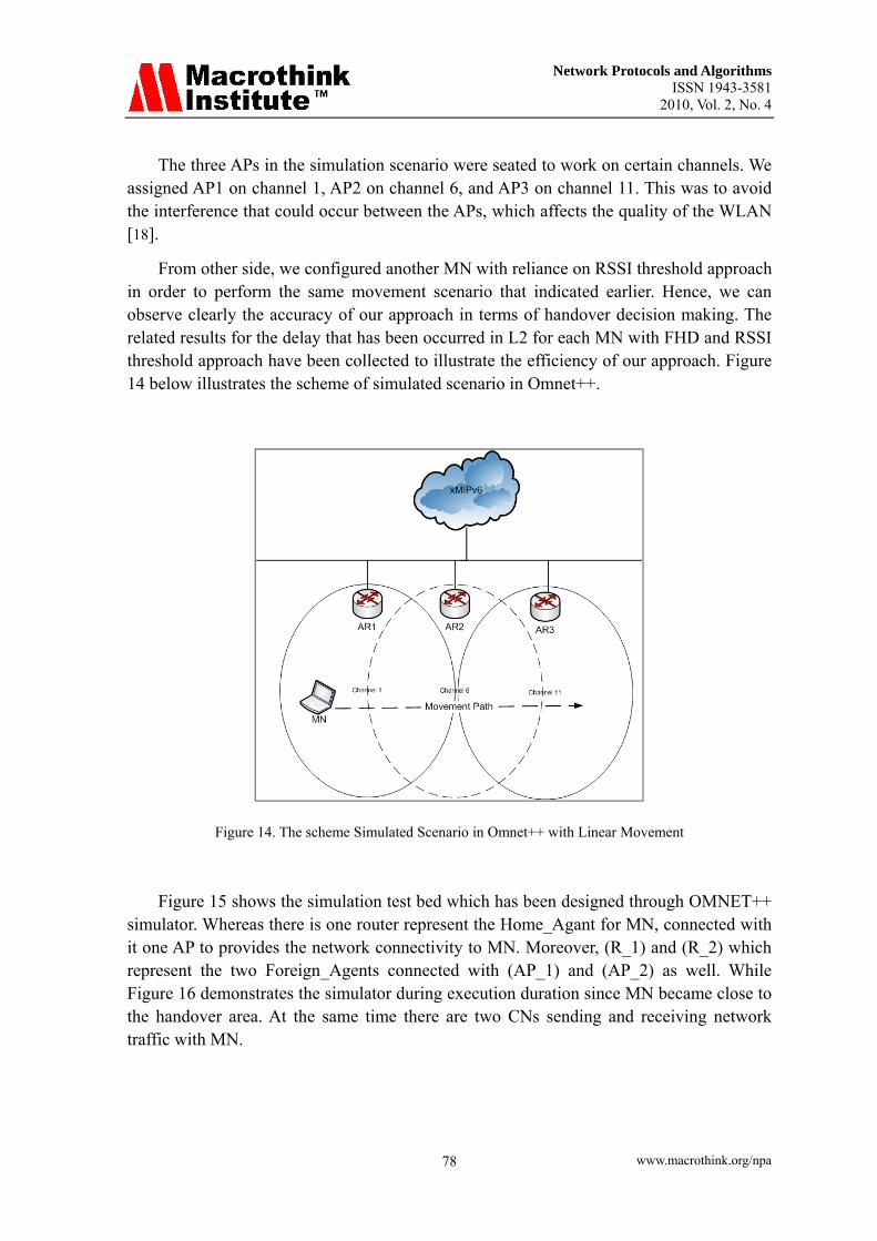
From other side, we configured another MN with reliance on RSSI threshold approach in order to perform the same movement scenario that indicated earlier. Hence, we can observe clearly the accuracy of our approach in terms of handover decision making. The related results for the delay that has been occurred in L2 for each MN with FHD and RSSI threshold approach have been collected to illustrate the efficiency of our approach. Figure 14 below illustrates the scheme of simulated scenario in Omnet++.
Figure 14. The scheme Simulated Scenario in Omnet++ with Linear Movement
Figure 15 shows the simulation test bed which has been designed through OMNET++ simulator. Whereas there is one router represent the Home_Agant for MN, connected with it one AP to provides the network connectivity to MN. Moreover, (R_1) and (R_2) which represent the two Foreign_Agents connected with (AP_1) and (AP_2) as well. While Figure 16 demonstrates the simulator during execution duration since MN became close to the handover area. At the same time there are two CNs sending and receiving network traffic with MN.

Network Protocols and Algorithms ISSN 1943-3581
2010, Vol. 2, No. 4
www.macrothink.org/npa 79
Figure 15. Simulation scenario in OMNET++
Figure. 16. The execution view for simulation’s scenario in OMNET++
6.2 Simulation Results
After we constructed and configured the simulation scenario, the required results were collected. In this section, we discuss the results for two scenarios. The first, which was represented a MN with undirected trajectory (non-linear movement), we will call scenario A. The second, with directed trajectory (linear movement), we will call scenario B. The results for both scenarios were collected and are shown in Figure 17 (the MN’s tracked movement in scenario A), and Figure 18 (movement for the MN in scenario B).

Network Protocols and Algorithms ISSN 1943-3581
2010, Vol. 2, No. 4
www.macrothink.org/npa 80
Figure 17. non-linear Movement for MN Scenario (A)
Figure 18. Linear Movement for MN Scenario (B)
Since our FHD approach was applied in the probe (scanning) phase (one of the L2 handover phases), the metric traced via running the simulation was the Wireless Access Media Delay in the MN, which refers to the MAC delay (Layer 2). Figure 19, exhibits the delay that occurred in Layer 2 of the MN during its movement from the HA trends to other APs belonging to the FAs. In this scenario (A), the MN moved in an undirected way to APR2, which means the MN handover decision depends on the angle of direction between itself and other APs and the value of scanning for RSSI. This was done using the FHD approach, which assists in decreasing the handover latency in L2 so that the overall latency decreases.
In Figure 19, scenario A shows that the MN started its movement from it’s HA to the

Network Protocols and Algorithms ISSN 1943-3581
2010, Vol. 2, No. 4
www.macrothink.org/npa 81
other two APs belonging to the FA. Initially, the handover latency in Layer 2 was zero at the beginning of movement; then it rose acutely after the third meter of movement away from the HA. The delay continued to increase until it reached 2.19 seconds. At that time, the MN started to move away from AP1 (HA) and enter the AP2 range, which belonged to FA1. From this scenario, we can observe the effectiveness of the FHD approach in terms of handover decision making. When the MN was working with AP1 after 2 m, the FHD calculated the Quality-Cost for AP3 belonging to FA2, which was higher than the AP2 belonging to FA1. Therefore, the handover decision was taken to perform the handover procedure with this AP3. We then monitored the curve after the first meter had risen sharply because the L2 handover started with AP3. Figure 19 also illustrates that the delay curve declines consistently after the fifth meter of movement, which means the MN was working with AP3 during all the remaining meters of simulation.
Figure 19. Wireless Media Access Delay (L2 Delay) in MN Moving in an Undirected way to APR2
On the other hand, scenario B applied a specified linear movement direction for the MN. The results illustrated in Figure 20 refer to the linear movement for the MN in scenario B. From Figure 20, we can extract that when the MN started its movement of the first half metre, the Layer 2 handover latency was zero. That is because, at that time, the MN was still connected with its HA and had a good coverage area (RSSI quality), which means there was no handover process needed. When the MN started to draw near to the second AP (in the handover area), the curve shows the delay for L2 developing (0.0010 seconds) and gradually starting to rise, until reaching the value of delay (0.0024 seconds). This delay occurred since the signaling for L2 had started with the next available AP in the range in the third meter of the MN’s movement. Then after three meters, the delay started to decrease to 0.0020 seconds, which was when the MN entered

Network Protocols and Algorithms ISSN 1943-3581
2010, Vol. 2, No. 4
www.macrothink.org/npa 82
AP2’s range of service. At this point, the MN started signaling to AP3, which was the next AP in the MN’s movement track. During the remaining distance of movement for the MN (up to 14 m), it was connected to AP3 and the L2 delay was between 0.0017–0.0018 seconds.
Figure 20. Wireless Media Access Delay (L2 Delay) in MN Directed Linear Movement
Throughout the previous scenario, we can detect that the MN conducted the handover with two APs, which belonged to FA1 and 2. This happened while all of them were in the same relative direction with the MN. At the same time, these APs had a good RSSI value. Therefore, the FHD considered all the APs in this scenario as having a very high Quality-Cost, so the MN was able to process the handover with them. The handover latency in L2 was seamless and had a low latency in this scenario, which is obvious from the results collected for the wireless access media delay, shown in Figure 20.
Figure 21 shows the APs’ connectivity with the MN during meters of movement for scenario A (non-linear movement) and B (linear movement), where the FHD approach has been applied. In scenario A, the simulated scenario’s trajectory distance was 20 m, whereas in scenario B, it was 14 m.
From the discussed results, we can calculate that when a FHD approach is used with a MN to support the handover decision-making process, it helps to reduce the handover latency in L2. In scenario A, FHD acts as an essential rule in terms of obtaining the right handover decision with AP3; it did not perform the handover with AP2 since the AP was not in a relative direction with the MN. Therefore, for FHD, the handover decision is more accurate.

Network Protocols and Algorithms ISSN 1943-3581
2010, Vol. 2, No. 4
www.macrothink.org/npa 83
Figure 21. The Active AP for MN in Meters of Movement
In order to investigate the handover (L2 handover latency) process of the default (and our) approach, we show, in Figure 22, the wireless access media delay, which occurred when we ran the simulation in scenario A (Figure 17 shows the default handover procedure). In Figure 22, the L2 handover latency trend rose acutely at 4 m. This is no surprise, since the default approach was used without predicting the handover decision. Next, the MN entered the AP2 and the latency reached 10 seconds. This was due to the L2 handover signal. When the MN started to move in another direction (away from AP2), it decided to undertake the second handover process with AP3. Then the latency decreased consistently until it reached 2.8 seconds at 18 m, which means the MN, started working with AP3 after the handover process was settled.
From our results and an analysis of Figure 22, it is fair to suggest that the handover decision based on a single parameter (RSSI) offers higher handover latency. This is evidenced by the fact that although the MN was not directed towards AP2, the handover still occurred.

Network Protocols and Algorithms ISSN 1943-3581
2010, Vol. 2, No. 4
www.macrothink.org/npa 84
Figure 22. Wireless Access Media Delay (L2 Delay) in MN, Scenario A with Proof of Default Handover
In the way to achieve more justification for our approach’s accuracy in terms of handover decision making, we have done another simulation scenario which we called Scenario C in Figure 23. In this scenario we have assigned two MNs, one working based on FHD in handover decision making and the second depends on RSSI threshold approach. These two MNs tested with three APs one belong to HA and the others to FAs. The delay which occurred in wireless media access L2 has been shown in Figure 24.
Figure 23. Scenario C with two MNs (Comparison FHD and RSSI threshold approaches)

Network Protocols and Algorithms ISSN 1943-3581
2010, Vol. 2, No. 4
www.macrothink.org/npa 85
From the top part of Figure 24, we can see that, when the MN which works with reliance on RSSI threshold approach started its movement at the first wireless access media delay was zero. After the second meter the delay has been increased to reach 2 sec. This indicates to, the MN started performs L2 signaling in order to settle the handover with AP_1 which shown in Figure 23. Despite the fact that, MN after the fourth meter has been changed its direction of movement to the opposite side of that AP. After that, the curve for wireless Media access delay started to increase until it reached 3.5 Sec. This is due to the L2 process which has been taken place with AP_2 which started provides MN with better RSSI value than the current AP. Whereas, the MN in the 8th meter changed the direction of movement once again as Figure 23 depicts. Throughout this the delay has been increased sharply to be 9 Sec which means that MN started L2 signaling with next AP in order to handle the handover with it. Finally, the delay curve declined consistently until it reached 2.5 sec, this when MN went back to its HA.
Figure 24. Comparison between RSSI threshold and FHD approaches in terms of media access delay in Scenario C.
While the second part of Figure 24 illustrates that, the MN which relies on FHD approach in handover decision making, at the delay’s curve has been increased after the first meter to reaches 0.00015 sec. This when MN started only the scanning phase which is related to L2 phases in order to calculate the quality cost for each AP in the range by using FHD approach technique. From that the FHD provided the prediction for MN whereas its trajectory wasn’t related with APs in the range. Therefore, we can extract that from curve
Network Protocols and Algorithms ISSN 1943-3581
2010, Vol. 2, No. 4
www.macrothink.org/npa 86
of delay in Figure 24 which related to MN with FHD approach has been decreased strongly after the second meter of movement until reached 0.00001 Sec in at 18 m.
From this point we can conclude that, the MN which relies on FHD achieved the right decision when didn’t undertake the handover with two APs (AP_1&AP_2) and kept connecting with its HA. Thus, the unworthy handovers which have been undertaken by the first MN which relies on RSSI threshold haven’t taken by MN relies on our FHD approach. Hence, the FHD approach is more helpfully in terms of provides the MN with accurate handover decisions which depends on RSSI and relative direction of the MN toward the APs.
7. Conclusion and Future Work
In this article, we proposed a unique fuzzy logic-based hand-off decision approach to predict the most qualified AP within its coverage. The Received Signal Strength Indicator of AP and relative direction of the MN toward the APs were considered as inputs to the fuzzy logic system. We showed that using our proposed approach and through simulation Omnet++, that latency in L2 decreased to achieve the adaptive handover decision. Moreover, a fair comparison was undertaken with a standard handover procedure in Fast Mobile IPv6 and RSSI threshold approach as well to justify the efficiency of our FHD approach. In future work, we will consider other important parameters, like interference, so that the FHD will reflect more accurate handover decision making. Moreover, the proposed FHD approach can be applied on different scenarios of mobility with various mobile densities to evaluate the efficiency of the proposed schema.
References
[1] R. Koodli, "Mobile IPv6 Fast Handovers," in IETF: IETF Request For Comments (RFC) 5268," 2008.
[2] T. Adiline Macriga, and P. Dr. Anandha Kumar, "Mobility Management for seamless Information flow in Heterogeneous Networks using Hybrid Handover," pp. 63-64, 2010.
[3] Xu. Changqing, Jin Teng, and Jia Weijia, "Enabling fast and smoother handoffs in AP-dense 802.11 wireless networks, on Electronic Engineering Departmen, Shanghai Jiao University, Shanghai, China," p. 1, 2010.
[4] S. Ryu, "Enhanced Fast Handover for Mobile IPv6 based on IEEE 802.11 Network, draft-mun-mipshop-efh-fast-mipv6-03.txt ," pp. 5–7, August 2009.
[5] S. Choi, G.H. Hwang, T. Kwon, A.R. Lim, and D.-H. Cho, "Fast handover scheme for real-time downlink services in IEEE 802.16e BWA system," in IEEE 61 stVehicular Technology Conference (VTC 2005), Vol. 3, 2005, pp. 2028-2032.
[6] Yu-Chee Tseng Ping-Jung Huang, "A Fast Handoff Mechanism for IEEE 802.11 and IAPP Networks," in Vehicular Technology Conference, VTC 206-Spring, IEEE 63rd vol. 2 , 2006, pp. 966-970.
[7] H. Kim, S. Park, C. Park, J KIm, and S. Ko, "Selective Channel Scanning for Fast
Network Protocols and Algorithms ISSN 1943-3581
2010, Vol. 2, No. 4
www.macrothink.org/npa 87
Handoff in Wireless LAN using Neighbour Graph ," in ITC-CSCC, July 2004. [8] Velayos, H. and G. Karlsson, "Techniques to Reduce IEEE 802.11b MAC Layer
Handoff Time ," in Laboratory for Communication Networks, KTH, Royal Institute of Technology, Stockholm, Sweden, TRITA-IMIT-LCN R 03:02, April 2003.
[9] Kyoungnam Kwon and Chaewoo Lee, "A Fast Handoff Algorithm using Intelligent Channel Scan for IEEE 802.11 WLANs," in IEEE 6 thInternational Conference, vol. 1, 2004, pp. 46-50.
[10] S. Shin, A. S. Rawat, H. Schulzrinne, "Reducing MAC Layer Handoff Latency in IEEE 802.11 Wireless LANs ," in ACM MobiWac, Oct. 2004.
[11] C.C. Tseng, K. H. Chi, M.D. Hsieh, and H.H. Chang, "Location-based fast handoff for 802.11 networks," in IEEE Communications letters, vol. 9, issue 4 , April 2005, pp. 304-306.
[12] R. Corvaja, A. Zanella, M. Dossi, A. Tontoli, and P. Zennaro, "Experimental performance of the handover procedure in a WiFi network ," in Proceedings of WPMC04, 2004.
[13] Ian F. Akyildiz, et. al, "Asurvey of Mobility Management in Next-Generration All-IP-Based Wireless Syastem ," in IEEE Wireless Communicqtions, August 2004.
[14] M. Hata, T. Nagatsu, "Mobile location using signal strength measurements in a cellular system," IEEE Transactions on Vehicular Technology 29 (2), pp. 245–252, 1980.
[15] Cem Ersoy, Erdal Cayirci, Gerard Parr Tolga Onel, "A multicriteria hando� decision scheme for the next generation tactical communications systems," Computer Networks 46, elsevier, p. 696, 10 July 2004.
[16] Chiew Foong Kwong, Teong Chee Chuah, and Sze Wei Lee, "Adaptive Network Fuzzy Inference System (ANFIS) Handoff Algorithm ," International Journal of Network and Mobile Technologies ISSN 1832-6758 Electronic Version , vol. 1, no. 2, NOVEMBER 2010.
[17] Jaroslav Holis and Pavel Pechac, "Elevation Dependent Shadowing Model for Mobile Communications via High Altitude Platforms in Built-Up Areas," IEEE TRANSACTIONS ON ANTENNAS AND PROPAGATION, VOL. 56, NO4, APRIL 2008.
[18] E.H. Mamdani, "Application of fuzzy logic to approximate reasoning using linguistic synthesis," IEEE Trans. on Computers, vol. C-26, pp. 1182-1191, Dec 1977.
[19] OMNET++ Descrete Event Simulation System. [Online] http://www.omnetpp.org/. [20] K.R.Rao, ZoranS.Bojkovic, Dragorad A.Milovanovic, Wireless Multimedia
Communications, Convergence, DSP,QoS, and Security.: Taylor & Francis Group, LLC, 2009.
Copyright Disclaimer
Copyright reserved by the author(s).
This article is an open-access article distributed under the terms and conditions of the Creative Commons Attribution license (http://creativecommons.org/licenses/by/3.0/).


![A Novel Approach to Reduce Handover Latency in Proxy ... · This makes force to improve ... PMIPv6 Route Optimization focuses the problem of overhead [11]. To solve this problem,](https://img.pdfslide.net/doc/110x75/5ea5d07c2513426621261b0f/a-novel-approach-to-reduce-handover-latency-in-proxy-this-makes-force-to-improve.jpg)