Embed Size (px)
Citation preview
1
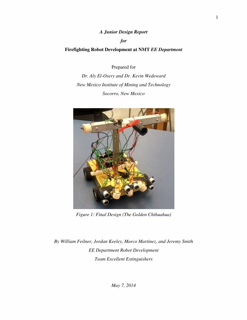
A Junior Design Report
for
Firefighting Robot Development at NMT EE Department
Prepared for
Dr. Aly El-Osery and Dr. Kevin Wedeward
New Mexico Institute of Mining and Technology
Socorro, New Mexico
Figure 1: Final Design (The Golden Chihuahua)
By William Feilner, Jordan Keeley, Marco Martinez, and Jeremy Smith
EE Department Robot Development
Team Excellent Extinguishers
May 7, 2014
2
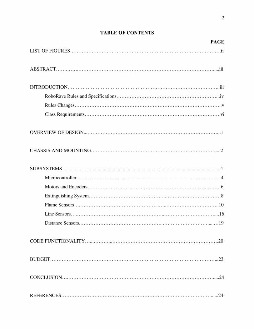
TABLE OF CONTENTS
PAGE
LIST OF FIGURES……………………………………………………………………………….ii
ABSTRACT…….…….……………………………………………………………………….....iii
INTRODUCTION………………………………………………………………………………..iii
RoboRave Rules and Specifications……………………………………………………...iv
Rules Changes……………………………………………………………………………..v
Class Requirements……………………………………………………………………….vi
OVERVIEW OF DESIGN...……………………………………………………………………...1
CHASSIS AND MOUNTING…………………………………………………………………....2
SUBSYSTEMS…………………………………………………………………………………...4
Microcontroller….…………………………………………………………………….…..4
Motors and Encoders………………………………………..………………………….…6
Extinguishing System………………………………………..……………………………8
Flame Sensors….………………………………………...…..…………………………..10
Line Sensors….……………………………………………..…………………………....16
Distance Sensors.…………………………………………..……………………….....…19
CODE FUNCTIONALITY…...………...……………………………………………………….20
BUDGET………………………………………………………………………………………...23
CONCLUSION….…………………………………………………………………………….....24
REFERENCES………………………………………………………………………………......24
3
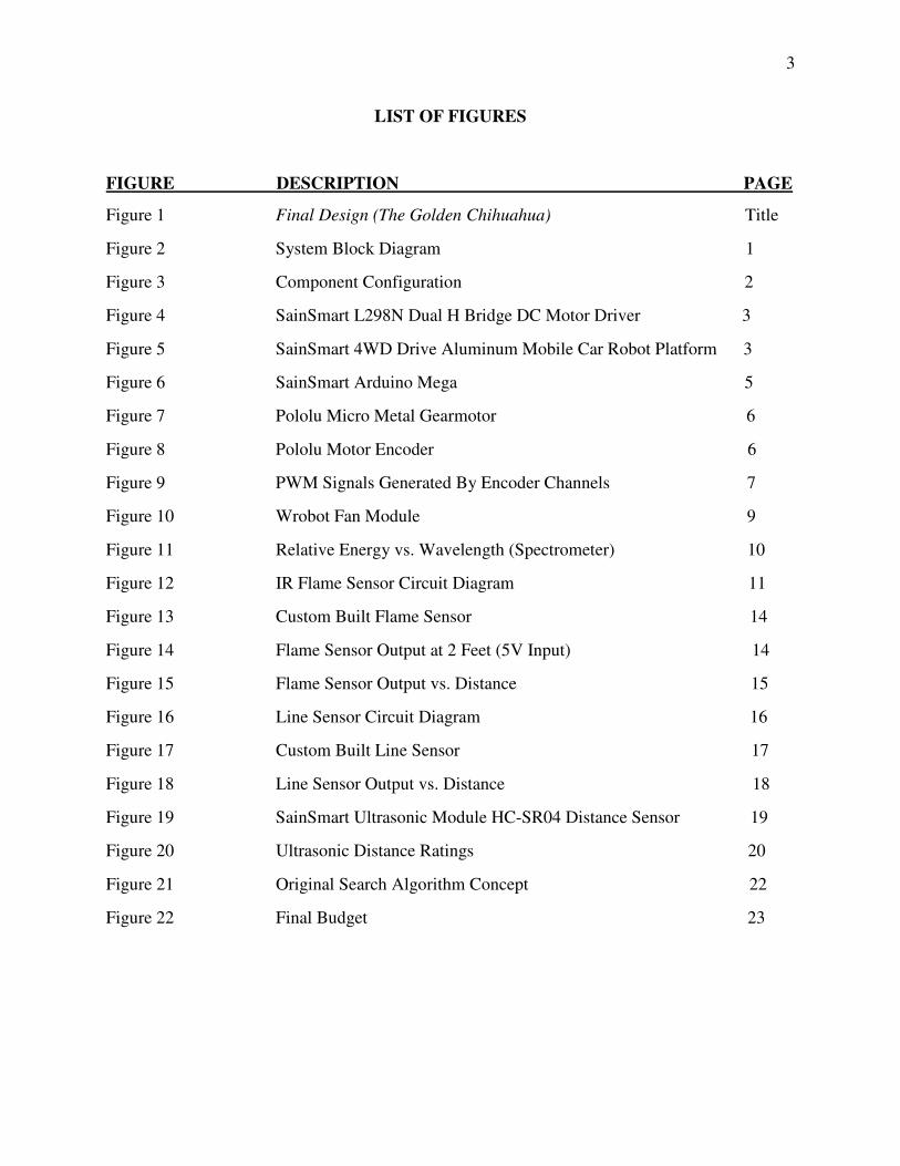
LIST OF FIGURES
FIGURE DESCRIPTION PAGE
Figure 1 Final Design (The Golden Chihuahua) Title
Figure 2 System Block Diagram 1
Figure 3 Component Configuration 2
Figure 4 SainSmart L298N Dual H Bridge DC Motor Driver 3
Figure 5 SainSmart 4WD Drive Aluminum Mobile Car Robot Platform 3
Figure 6 SainSmart Arduino Mega 5
Figure 7 Pololu Micro Metal Gearmotor 6
Figure 8 Pololu Motor Encoder 6
Figure 9 PWM Signals Generated By Encoder Channels 7
Figure 10 Wrobot Fan Module 9
Figure 11 Relative Energy vs. Wavelength (Spectrometer) 10
Figure 12 IR Flame Sensor Circuit Diagram 11
Figure 13 Custom Built Flame Sensor 14
Figure 14 Flame Sensor Output at 2 Feet (5V Input) 14
Figure 15 Flame Sensor Output vs. Distance 15
Figure 16 Line Sensor Circuit Diagram 16
Figure 17 Custom Built Line Sensor 17
Figure 18 Line Sensor Output vs. Distance 18
Figure 19 SainSmart Ultrasonic Module HC-SR04 Distance Sensor 19
Figure 20 Ultrasonic Distance Ratings 20
Figure 21 Original Search Algorithm Concept 22
Figure 22 Final Budget 23
4
ABSTRACT
A fully autonomous firefighting robot was constructed that included two custom sensors.
The robot was demonstrated to be capable of calculating its distance from an inanimate object
using ultrasonic distance sensors, distance from a lit candle using IR flame sensors, the relative
color of the ground it passed over using IR line sensors, and the distance it travelled using motor
encoders. In addition, the robot used a motor driver circuit, motors, and four wheels to maneuver
itself around a designated field and position itself within extinguishing range of the fire danger.
The extinguishing system was shown to be appropriately powerful to only extinguish the flame
when within the correct range. Finally, all subsystems were integrated into a fully functional
autonomous robot that was able to extinguish four flames in under three minutes.
INTRODUCTION
The EE 382 project chosen by the group was the RoboRave firefighting challenge. The
core task assigned was to create and program a fully autonomous robot that could avoid
obstacles, detect and extinguish candles within a 3 minute time frame. Custom components
applying concepts from either analog electronic or electricity and magnetism courses were also
required. The problem solving approach taken by the team to complete the task divided the robot
up into 5 subsystems: Flame sensing, distance sensing and line sensing, extinguishing and
movement. An Arduino based microcontroller (SainSmart Mega) was used to control all
subsystems. As the extinguishing system was a single fan, it was easily integrated. The custom
line component the group decided on was a photosensitive circuit whose voltage output could be
interpreted by the on board analog to digital converters in the microcontroller. 3 ultrasonic
5
distance sensors were utilized to detect distance relative to the robot. An H bridge motor
controller was controlled with the controller via PWM (pulse width modulated) signals to
monitor and manipulate motor rotations. To identify obstacles and find candles, a searching
algorithm was programmed so that the robot navigated evenly throughout the playing area.
Once the project was complete, the robot ran on a candle course in lab and later at the official
RoboRave competition in Albuquerque, NM.
The Fire Fighting challenge rules, as defined by RoboRave:
Autonomous robot programed on any platform.
Programming that will move the robot within 8 inches (20.3 cm) or less of a candle before
extinguishing the flame.
Extinguishing system that does not require direct contact with the candle.
Complete system cost that does not exceed $1500 total value (regardless of how the parts were
acquired).Teams must be able to produce an itemized materials list if cost is called into question
during the competition
Playing field specifications:
A white, 1.0 inch (2.54 cm) wide circle with an 8″ (20.3 cm) radius, as measured from the
candle’s base, will be marked on the track around each candle Robot starts at a predesignated
area on corner of track. The candle’s base diameter is 2.75 inches (7 cm).
Some part of the robot must be on or inside the circle while the candle is extinguished; if the
robot is NOT on or inside the circle, and the candle is extinguished, a 50% penalty of the
candle’s value will be deducted.
6
The robot will have 3 minutes to extinguish the candles.
Robot’s base area must be 144 square inches (929 square cm) or less; the robot’s height,
however, can be unlimited.
The mechanism for extinguishing any candle must be programmed to turn ON only after it stops
at a candle and then turns OFF while it seeks the next candle; the robot may operate inside,
along, or outside the perimeter border; the border is provided for those teams who design to use a
line following sensor.
Touching your robot during 3-minute heat ends the heat; however, multiple heats can be run by
the same team on one of 4 tracks, chosen by the team.
Any team that successfully extinguishes ALL four candles during a 3-minute TOURNAMENT
heat (not during morning trials) wins the Wilkinson Award ($200).
Rules Changes During Competition:
The rules given to teams on site stated that the fan mechanism may be on at all times, regardless
of the distance to the candle. Also, the circles around the candle, now a white paper with a black
line printed on it, were optional and teams could run trials with or without the circles. Candles
were also allowed to be tipped over after they were extinguished.
7
Class Requirements:
In addition to following the RoboRave rules, some parameters were set as part of EE 382:
The robot may not be a previously fabricated system, (such as Lego Mindstorms). Also, the use
of custom individual components was strongly encouraged to prevent the project from being
entirely code-based. A $325 dollar budget was given to the group, as well as access to the spare
parts from previous EE 382 projects. One of the main requirements outlined in the junior design
project was the design and implementation of a key component using concepts from Analog or
Electricity and Magnetism courses.
OVERVIEW OF DESIGN
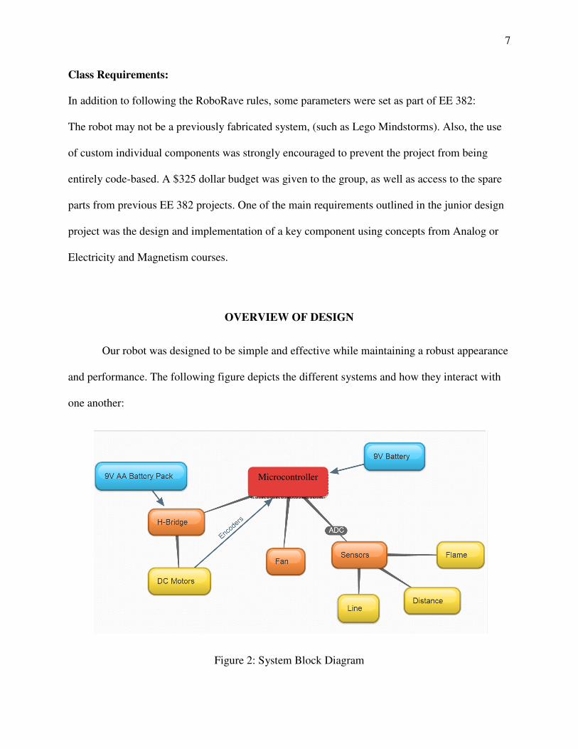
Our robot was designed to be simple and effective while maintaining a robust appearance
and performance. The following figure depicts the different systems and how they interact with
one another:
Figure 2: System Block Diagram
Microcontroller
8
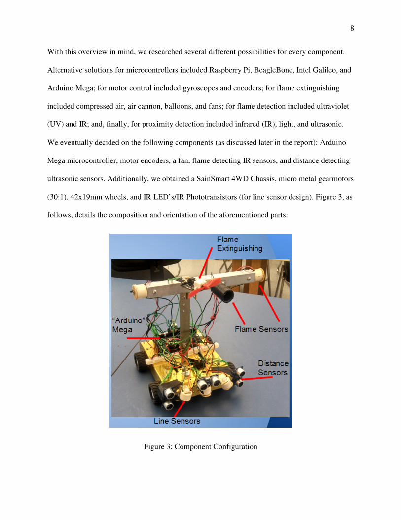
With this overview in mind, we researched several different possibilities for every component.
Alternative solutions for microcontrollers included Raspberry Pi, BeagleBone, Intel Galileo, and
Arduino Mega; for motor control included gyroscopes and encoders; for flame extinguishing
included compressed air, air cannon, balloons, and fans; for flame detection included ultraviolet
(UV) and IR; and, finally, for proximity detection included infrared (IR), light, and ultrasonic.
We eventually decided on the following components (as discussed later in the report): Arduino
Mega microcontroller, motor encoders, a fan, flame detecting IR sensors, and distance detecting
ultrasonic sensors. Additionally, we obtained a SainSmart 4WD Chassis, micro metal gearmotors
(30:1), 42x19mm wheels, and IR LED’s/IR Phototransistors (for line sensor design). Figure 3, as
follows, details the composition and orientation of the aforementioned parts:
Figure 3: Component Configuration
9
CHASSIS AND MOUNTING
As seen in Figure 3, the sensors (three of each: flame, distance, and line) and the fan are
located on the front end of the robot, and the microcontroller is located on the back. The 9V
battery supplying power to the microcontroller
is also mounted on the back. Inside the robot
are the motors, motor encoders (on the front
two motors), a motor controller/driver, and six
AA batteries in series (totaling 9V) to power
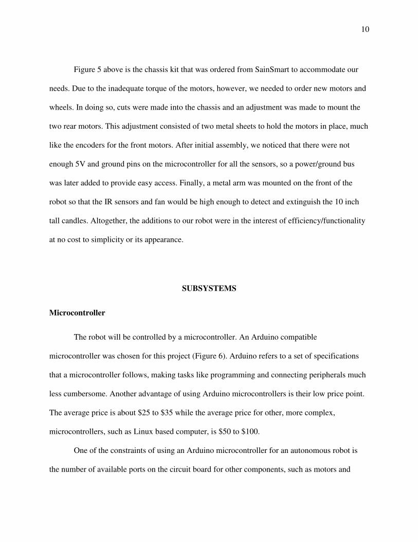
the motor controller. The motor controller, as
pictured in Figure 4 below, was controlled via
5V digital output from the microcontroller. Of
the four outputs, two were designated as a
positive (forward) charge to the motors and two were negatively (reverse) charged.
Figure 4: SainSmart L298N
Dual H Bridge DC Motor Driver
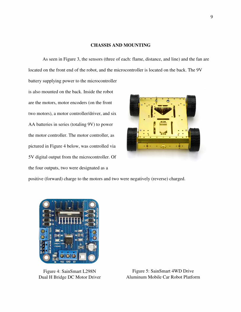
Figure 5: SainSmart 4WD Drive
Aluminum Mobile Car Robot Platform
10
Figure 5 above is the chassis kit that was ordered from SainSmart to accommodate our
needs. Due to the inadequate torque of the motors, however, we needed to order new motors and
wheels. In doing so, cuts were made into the chassis and an adjustment was made to mount the
two rear motors. This adjustment consisted of two metal sheets to hold the motors in place, much
like the encoders for the front motors. After initial assembly, we noticed that there were not
enough 5V and ground pins on the microcontroller for all the sensors, so a power/ground bus
was later added to provide easy access. Finally, a metal arm was mounted on the front of the
robot so that the IR sensors and fan would be high enough to detect and extinguish the 10 inch
tall candles. Altogether, the additions to our robot were in the interest of efficiency/functionality
at no cost to simplicity or its appearance.
SUBSYSTEMS
Microcontroller
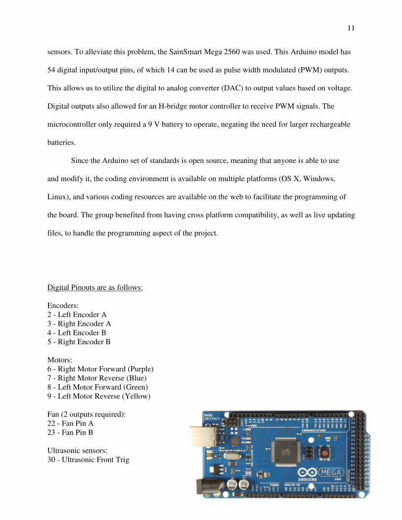
The robot will be controlled by a microcontroller. An Arduino compatible
microcontroller was chosen for this project (Figure 6). Arduino refers to a set of specifications
that a microcontroller follows, making tasks like programming and connecting peripherals much
less cumbersome. Another advantage of using Arduino microcontrollers is their low price point.
The average price is about $25 to $35 while the average price for other, more complex,
microcontrollers, such as Linux based computer, is $50 to $100.
One of the constraints of using an Arduino microcontroller for an autonomous robot is
the number of available ports on the circuit board for other components, such as motors and
11
sensors. To alleviate this problem, the SainSmart Mega 2560 was used. This Arduino model has
54 digital input/output pins, of which 14 can be used as pulse width modulated (PWM) outputs.
This allows us to utilize the digital to analog converter (DAC) to output values based on voltage.
Digital outputs also allowed for an H-bridge motor controller to receive PWM signals. The
microcontroller only required a 9 V battery to operate, negating the need for larger rechargeable
batteries.
Since the Arduino set of standards is open source, meaning that anyone is able to use
and modify it, the coding environment is available on multiple platforms (OS X, Windows,
Linux), and various coding resources are available on the web to facilitate the programming of
the board. The group benefited from having cross platform compatibility, as well as live updating
files, to handle the programming aspect of the project.
Digital Pinouts are as follows:
Encoders: 2 - Left Encoder A 3 - Right Encoder A 4 - Left Encoder B 5 - Right Encoder B Motors: 6 - Right Motor Forward (Purple) 7 - Right Motor Reverse (Blue) 8 - Left Motor Forward (Green) 9 - Left Motor Reverse (Yellow) Fan (2 outputs required): 22 - Fan Pin A 23 - Fan Pin B Ultrasonic sensors: 30 - Ultrasonic Front Trig
12
31 - Ultrasonic Front Echo 32 - Ultrasonic Right Trig 33 - Ultrasonic Right Echo 34 - Ultrasonic Left Trig 35 - Ultrasonic Left Echo 6 analog pins are reserved for custom sensors: Line sensors: A0 - Line Sensor Front A1 - Line Sensor Right A2 - Line Sensor Left Flame Sensors: A8 - Flame Sensor Front A9 - Flame Sensor Right A10 - Flame Sensor Left
Motors and Encoders
The new motors used in our robot were from Pololu, with a gear ratio of 30:1 (see Figure
6). These motors, capable of outputting over 700 rpm and 8 oz-in. of torque, proved to be a
perfect choice for speed and accuracy. One downside, however, was the frequent need to
replace/recharge batteries inside the chassis, but at $16 each, they were well worth the price.
Primarily, these motors were chosen for their durability and ability to carry a loaded robot, both
successfully tested.
Figure 6: SainSmart Arduino Mega
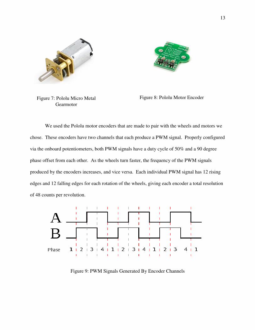
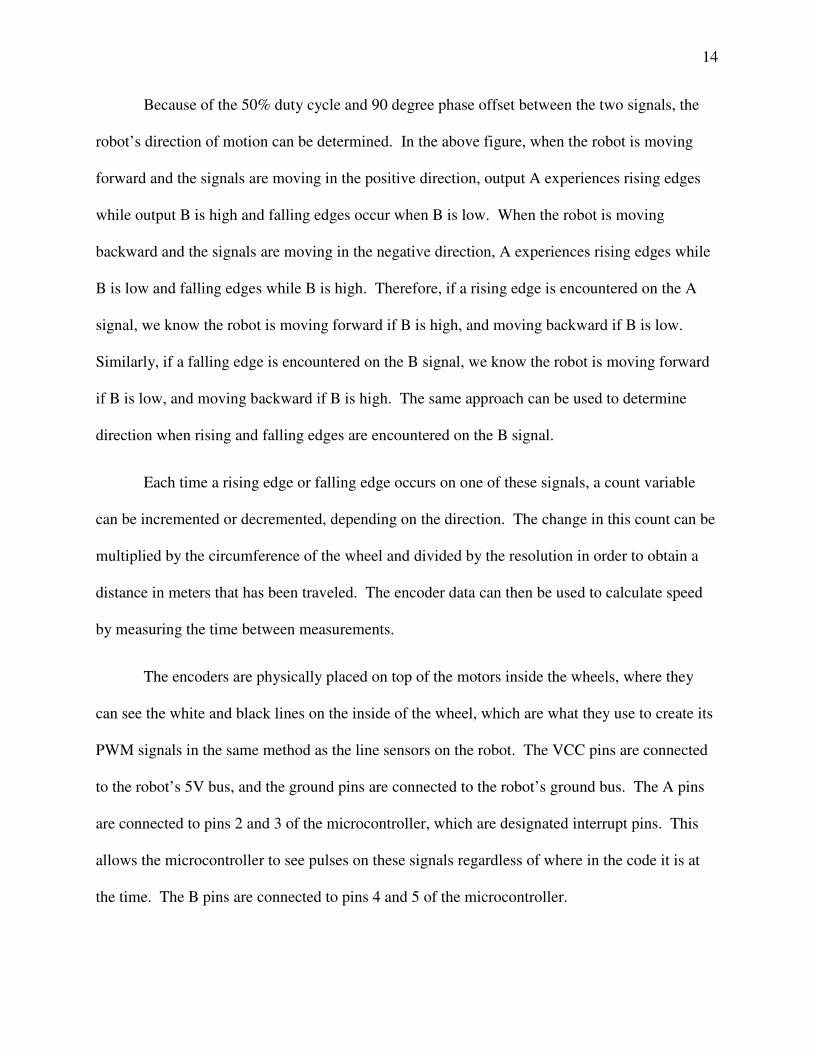
We used the Pololu motor encoders that are made to pair with the wheels and motors we
chose. These encoders have two channels that each produce
via the onboard potentiometers, both PWM signals have a duty cycle of 50% and a 90 degree
phase offset from each other. As the wheels turn faster, the frequency of the PWM signals
produced by the encoders increases, and vice versa. Each individual PWM signal has 12 rising
edges and 12 falling edges for each rotation of the wheels, giving each encoder a total resolution
of 48 counts per revolution.
Figure 9: PWM
Figure 7: Pololu Micro Metal
Gearmotor
We used the Pololu motor encoders that are made to pair with the wheels and motors we
two channels that each produce a PWM signal. Properly configured
via the onboard potentiometers, both PWM signals have a duty cycle of 50% and a 90 degree
phase offset from each other. As the wheels turn faster, the frequency of the PWM signals
by the encoders increases, and vice versa. Each individual PWM signal has 12 rising
edges and 12 falling edges for each rotation of the wheels, giving each encoder a total resolution
: PWM Signals Generated By Encoder Channels
Pololu Micro Metal Figure 8: Pololu Motor Encoder
13
We used the Pololu motor encoders that are made to pair with the wheels and motors we
PWM signal. Properly configured
via the onboard potentiometers, both PWM signals have a duty cycle of 50% and a 90 degree
phase offset from each other. As the wheels turn faster, the frequency of the PWM signals
by the encoders increases, and vice versa. Each individual PWM signal has 12 rising
edges and 12 falling edges for each rotation of the wheels, giving each encoder a total resolution
Pololu Motor Encoder
14
Because of the 50% duty cycle and 90 degree phase offset between the two signals, the
robot’s direction of motion can be determined. In the above figure, when the robot is moving
forward and the signals are moving in the positive direction, output A experiences rising edges
while output B is high and falling edges occur when B is low. When the robot is moving
backward and the signals are moving in the negative direction, A experiences rising edges while
B is low and falling edges while B is high. Therefore, if a rising edge is encountered on the A
signal, we know the robot is moving forward if B is high, and moving backward if B is low.
Similarly, if a falling edge is encountered on the B signal, we know the robot is moving forward
if B is low, and moving backward if B is high. The same approach can be used to determine
direction when rising and falling edges are encountered on the B signal.
Each time a rising edge or falling edge occurs on one of these signals, a count variable
can be incremented or decremented, depending on the direction. The change in this count can be
multiplied by the circumference of the wheel and divided by the resolution in order to obtain a
distance in meters that has been traveled. The encoder data can then be used to calculate speed
by measuring the time between measurements.
The encoders are physically placed on top of the motors inside the wheels, where they
can see the white and black lines on the inside of the wheel, which are what they use to create its
PWM signals in the same method as the line sensors on the robot. The VCC pins are connected
to the robot’s 5V bus, and the ground pins are connected to the robot’s ground bus. The A pins
are connected to pins 2 and 3 of the microcontroller, which are designated interrupt pins. This
allows the microcontroller to see pulses on these signals regardless of where in the code it is at
the time. The B pins are connected to pins 4 and 5 of the microcontroller.
15
We included these encoders on our robot because our original search algorithm required
distance data provided by them. We were planning to measure distances of the lines for
orientation. After the robot had traveled along the first two lines, it would know the distances of
all the lines, and would, therefore, know when it turns onto one of the two 12 foot lines. It would
then use distance data from the encoders again to travel 6 feet (halfway down the line) before
turning and crossing the field. However, when we changed from this search algorithm to the
current randomized one, we lost this use of the encoders. Therefore, although the encoders are
currently physically included on the robot, they are not integrated and used in the code. If we
had more time, we would likely use them to have the robot correct itself if it gets stuck on a wall.
Extinguishing System
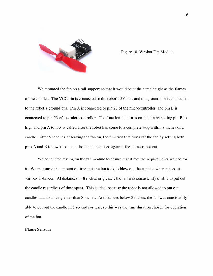
For our method of extinguishing candles, we chose the Wrobot Fan Module (see Figure
9). We chose this fan over other options due to its low cost, small size and weight, low power
usage, and ability to put out the candles within and only within a small distance. This fan has
four pins to control its operation: VCC, ground, A, and B. Pins A and B function as an H-bridge
to control the direction that the fan spins. The fan blows forward if pin B is high and pin A is
low, and blows backward if pin A is high and pin B is low. Setting both pins, A and B, low stops
the fan.
16
We mounted the fan on a tall support so that it would be at the same height as the flames
of the candles. The VCC pin is connected to the robot’s 5V bus, and the ground pin is connected
to the robot’s ground bus. Pin A is connected to pin 22 of the microcontroller, and pin B is
connected to pin 23 of the microcontroller. The function that turns on the fan by setting pin B to
high and pin A to low is called after the robot has come to a complete stop within 8 inches of a
candle. After 5 seconds of leaving the fan on, the function that turns off the fan by setting both
pins A and B to low is called. The fan is then used again if the flame is not out.
We conducted testing on the fan module to ensure that it met the requirements we had for
it. We measured the amount of time that the fan took to blow out the candles when placed at
various distances. At distances of 8 inches or greater, the fan was consistently unable to put out
the candle regardless of time spent. This is ideal because the robot is not allowed to put out
candles at a distance greater than 8 inches. At distances below 8 inches, the fan was consistently
able to put out the candle in 5 seconds or less, so this was the time duration chosen for operation
of the fan.
Flame Sensors
Figure 10: Wrobot Fan Module
17
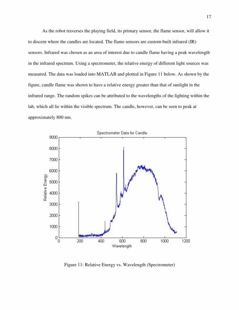
As the robot traverses the playing field, its primary sensor, the flame sensor, will allow it
to discern where the candles are located. The flame sensors are custom-built infrared (IR)
sensors. Infrared was chosen as an area of interest due to candle flame having a peak wavelength
in the infrared spectrum. Using a spectrometer, the relative energy of different light sources was
measured. The data was loaded into MATLAB and plotted in Figure 11 below. As shown by the
figure, candle flame was shown to have a relative energy greater than that of sunlight in the
infrared range. The random spikes can be attributed to the wavelengths of the lighting within the
lab, which all lie within the visible spectrum. The candle, however, can be seen to peak at
approximately 800 nm.
Figure 11: Relative Energy vs. Wavelength (Spectrometer)
As can be seen by Figure
electromagnetic spectrum, including ultraviolet, infrared, and the visible light spectrums.
However, candle flame has an energy presence only in the infrared and near
and is relatively higher than sunlight in the infrared range. Thus, infrared is a good choice when
attempting to measure candle flame while simultaneously rejecting sunlight. The circuit diagram
for our IR flame sensors is shown in Figure
Figure
The particular phototransistor is from Rohm Semiconductor and was chosen for its high
sensitivity, wavelength response, and visible light filter. As indicated by the datasheet, the
spectral response has a peak wavelength at 800 nm, corr
addition, the visible light filter, coupled with the specific spectral response will result in the
phototransistor rejecting all wavelengths in the visible light spectrum.
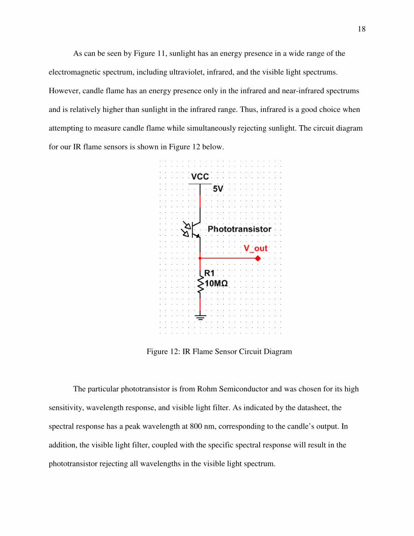
As can be seen by Figure 11, sunlight has an energy presence in a wide range of the
electromagnetic spectrum, including ultraviolet, infrared, and the visible light spectrums.
However, candle flame has an energy presence only in the infrared and near-infrared spectrums
gher than sunlight in the infrared range. Thus, infrared is a good choice when
attempting to measure candle flame while simultaneously rejecting sunlight. The circuit diagram
for our IR flame sensors is shown in Figure 12 below.
Figure 12: IR Flame Sensor Circuit Diagram
The particular phototransistor is from Rohm Semiconductor and was chosen for its high
sensitivity, wavelength response, and visible light filter. As indicated by the datasheet, the
spectral response has a peak wavelength at 800 nm, corresponding to the candle’s output. In
addition, the visible light filter, coupled with the specific spectral response will result in the
phototransistor rejecting all wavelengths in the visible light spectrum.
18
ght has an energy presence in a wide range of the
electromagnetic spectrum, including ultraviolet, infrared, and the visible light spectrums.
infrared spectrums
gher than sunlight in the infrared range. Thus, infrared is a good choice when
attempting to measure candle flame while simultaneously rejecting sunlight. The circuit diagram
The particular phototransistor is from Rohm Semiconductor and was chosen for its high
sensitivity, wavelength response, and visible light filter. As indicated by the datasheet, the
esponding to the candle’s output. In
addition, the visible light filter, coupled with the specific spectral response will result in the
19
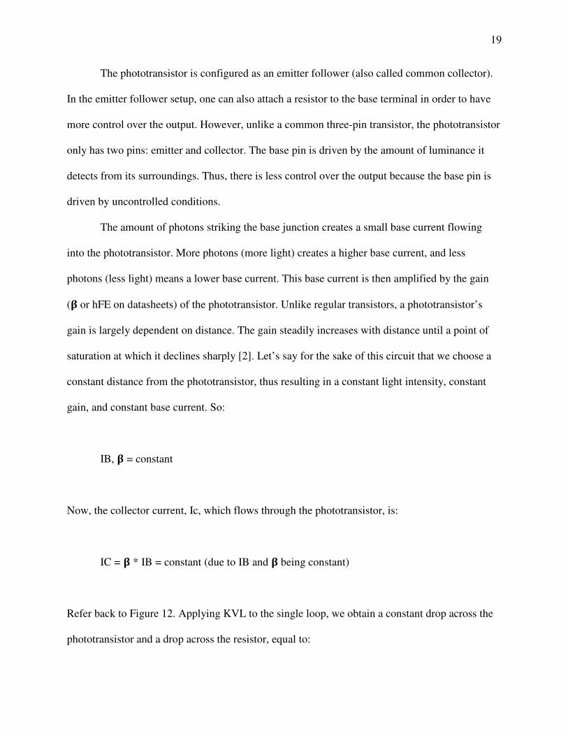
The phototransistor is configured as an emitter follower (also called common collector).
In the emitter follower setup, one can also attach a resistor to the base terminal in order to have
more control over the output. However, unlike a common three-pin transistor, the phototransistor
only has two pins: emitter and collector. The base pin is driven by the amount of luminance it
detects from its surroundings. Thus, there is less control over the output because the base pin is
driven by uncontrolled conditions.
The amount of photons striking the base junction creates a small base current flowing
into the phototransistor. More photons (more light) creates a higher base current, and less
photons (less light) means a lower base current. This base current is then amplified by the gain
(� or hFE on datasheets) of the phototransistor. Unlike regular transistors, a phototransistor’s
gain is largely dependent on distance. The gain steadily increases with distance until a point of
saturation at which it declines sharply [2]. Let’s say for the sake of this circuit that we choose a
constant distance from the phototransistor, thus resulting in a constant light intensity, constant
gain, and constant base current. So:
IB, � = constant
Now, the collector current, Ic, which flows through the phototransistor, is:
IC = � * IB = constant (due to IB and � being constant)
Refer back to Figure 12. Applying KVL to the single loop, we obtain a constant drop across the
phototransistor and a drop across the resistor, equal to:
20
VR = IC * R
where the only variable here is now the resistance because VR is constrained to be:
0 = 5 - Vphototransistor - VR
0 = 5 - Vphototransistor - Ic * R
As can be seen by this relationship, selecting a higher resistance means that the resulting output
will be higher (again for a constant distance from the component). Therefore, we can conclude
that the flame sensor is more sensitive with a higher resistance. By selecting a very large
resistance (10 M�), we ensure that the flame sensor achieves a high range of sensitivity,
meaning the robot can see a flame from further away.
The flame sensors were constructed using pre-printed round circuit boards purchased
from Radioshack. The two components were first soldered to the board, and wire wrapped to
make the appropriate electrical connections. For ease of use, three 20-gauge hookup wires were
also soldered to the PCB (red for power, green for output, and black for ground). By including
these three wires, physical interfacing between the custom component and the microcontroller
was made easier. The PCB was then adhered to a plastic housing to protect the internal circuitry.
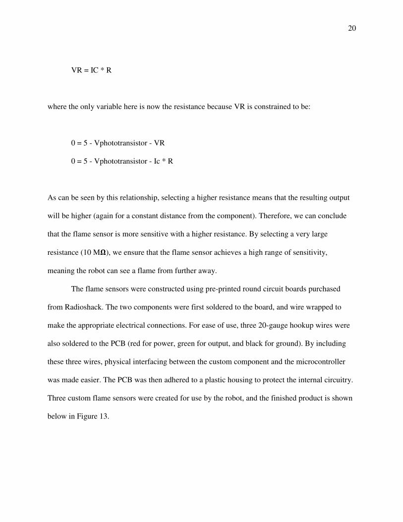
Three custom flame sensors were created for use by the robot, and the finished product is shown
below in Figure 13.
21
Figure 13: Custom Built Flame Sensor
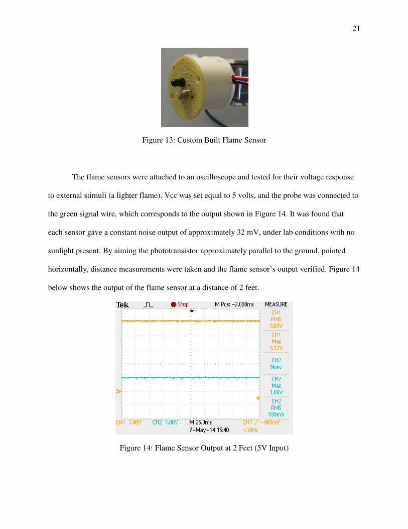
The flame sensors were attached to an oscilloscope and tested for their voltage response
to external stimuli (a lighter flame). Vcc was set equal to 5 volts, and the probe was connected to
the green signal wire, which corresponds to the output shown in Figure 14. It was found that
each sensor gave a constant noise output of approximately 32 mV, under lab conditions with no
sunlight present. By aiming the phototransistor approximately parallel to the ground, pointed
horizontally, distance measurements were taken and the flame sensor’s output verified. Figure 14
below shows the output of the flame sensor at a distance of 2 feet.
Figure 14: Flame Sensor Output at 2 Feet (5V Input)
22
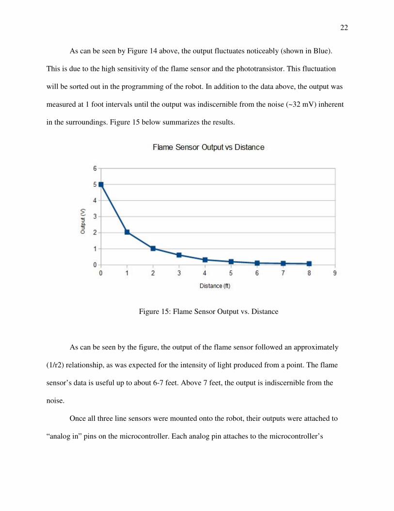
As can be seen by Figure 14 above, the output fluctuates noticeably (shown in Blue).
This is due to the high sensitivity of the flame sensor and the phototransistor. This fluctuation
will be sorted out in the programming of the robot. In addition to the data above, the output was
measured at 1 foot intervals until the output was indiscernible from the noise (~32 mV) inherent
in the surroundings. Figure 15 below summarizes the results.
Figure 15: Flame Sensor Output vs. Distance
As can be seen by the figure, the output of the flame sensor followed an approximately
(1/r2) relationship, as was expected for the intensity of light produced from a point. The flame
sensor’s data is useful up to about 6-7 feet. Above 7 feet, the output is indiscernible from the
noise.
Once all three line sensors were mounted onto the robot, their outputs were attached to
“analog in” pins on the microcontroller. Each analog pin attaches to the microcontroller’s
23
analog-to-digital converter (ADC). This particular ADC is a 10-bit ADC which results in an
output from digital 0 (0 volts from the sensor) up to a digital 1023 (5 volts from the sensor).
Line Sensors
According to the RoboRave rules, “a white PVC vinyl border measuring 3 inch (7.6 cm)
wide containing a 1 inch (2.54 cm) wide flat black line in the middle outlines the perimeter”. In
other words, an alternating white and black line will mark the boundaries of the playing field.
While operating inside the boundaries is not required, it is a good choice because the robot runs
the risk of never returning to the field. Thus, a line sensor was required for our robot to remain
within the boundaries and stay on task in finding and extinguishing candles. The line sensors
were custom-built IR emitter and receiver pairs, coupled together to measure the reflectance of
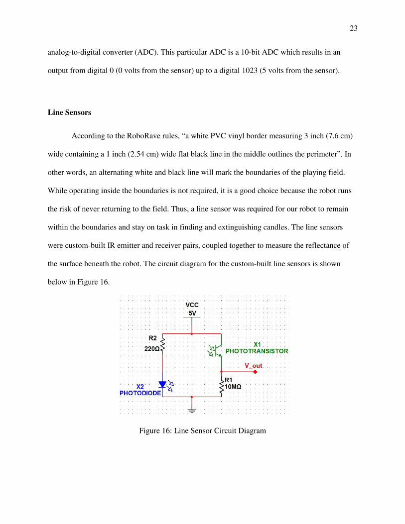
the surface beneath the robot. The circuit diagram for the custom-built line sensors is shown
below in Figure 16.
Figure 16: Line Sensor Circuit Diagram
24
The operation for this circuit is the same as the operation of the IR flame sensor, but with
one major difference. In the line sensor circuit, the IR emitter is internal to the circuit in the form
of an IR LED (unlike the flame sensor where the IR emitter is external to the circuit in the form
of the lit candle).
The line sensors were constructed using the same pre-printed circuit boards from
Radioshack. They were then wire-wrapped to make the appropriate electrical connections, and
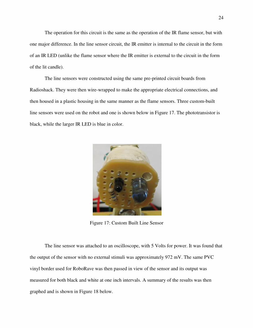
then housed in a plastic housing in the same manner as the flame sensors. Three custom-built
line sensors were used on the robot and one is shown below in Figure 17. The phototransistor is
black, while the larger IR LED is blue in color.
Figure 17: Custom Built Line Sensor
The line sensor was attached to an oscilloscope, with 5 Volts for power. It was found that
the output of the sensor with no external stimuli was approximately 972 mV. The same PVC
vinyl border used for RoboRave was then passed in view of the sensor and its output was
measured for both black and white at one inch intervals. A summary of the results was then
graphed and is shown in Figure 18 below.
25
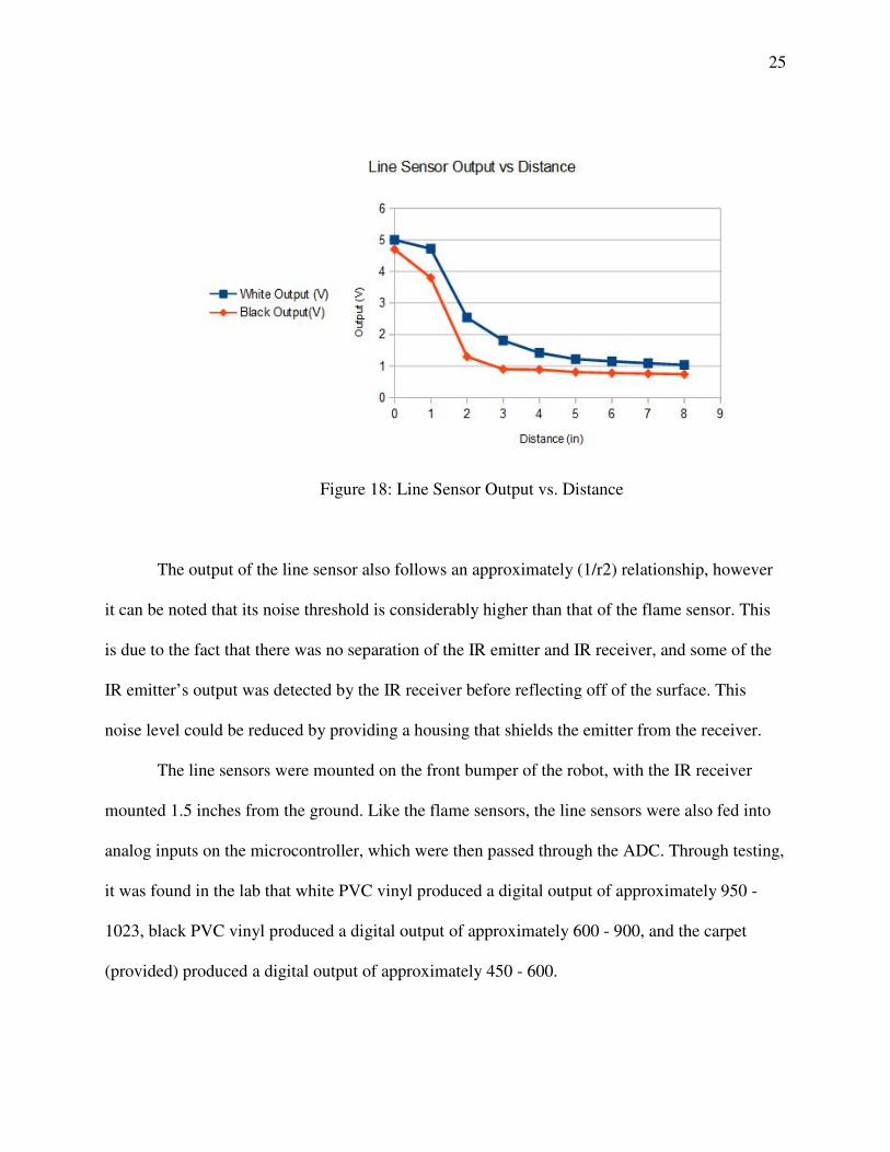
Figure 18: Line Sensor Output vs. Distance
The output of the line sensor also follows an approximately (1/r2) relationship, however
it can be noted that its noise threshold is considerably higher than that of the flame sensor. This
is due to the fact that there was no separation of the IR emitter and IR receiver, and some of the
IR emitter’s output was detected by the IR receiver before reflecting off of the surface. This
noise level could be reduced by providing a housing that shields the emitter from the receiver.
The line sensors were mounted on the front bumper of the robot, with the IR receiver
mounted 1.5 inches from the ground. Like the flame sensors, the line sensors were also fed into
analog inputs on the microcontroller, which were then passed through the ADC. Through testing,
it was found in the lab that white PVC vinyl produced a digital output of approximately 950 -
1023, black PVC vinyl produced a digital output of approximately 600 - 900, and the carpet
(provided) produced a digital output of approximately 450 - 600.
26
Distance Sensors
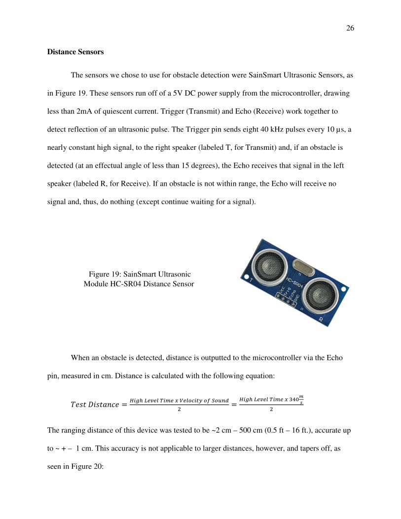
The sensors we chose to use for obstacle detection were SainSmart Ultrasonic Sensors, as
in Figure 19. These sensors run off of a 5V DC power supply from the microcontroller, drawing
less than 2mA of quiescent current. Trigger (Transmit) and Echo (Receive) work together to
detect reflection of an ultrasonic pulse. The Trigger pin sends eight 40 kHz pulses every 10 µs, a
nearly constant high signal, to the right speaker (labeled T, for Transmit) and, if an obstacle is
detected (at an effectual angle of less than 15 degrees), the Echo receives that signal in the left
speaker (labeled R, for Receive). If an obstacle is not within range, the Echo will receive no
signal and, thus, do nothing (except continue waiting for a signal).
When an obstacle is detected, distance is outputted to the microcontroller via the Echo
pin, measured in cm. Distance is calculated with the following equation:
���� ������ ���� ����� ���� � �������� �� �� !"
#
���� ����� ���� � $%&'
(
#
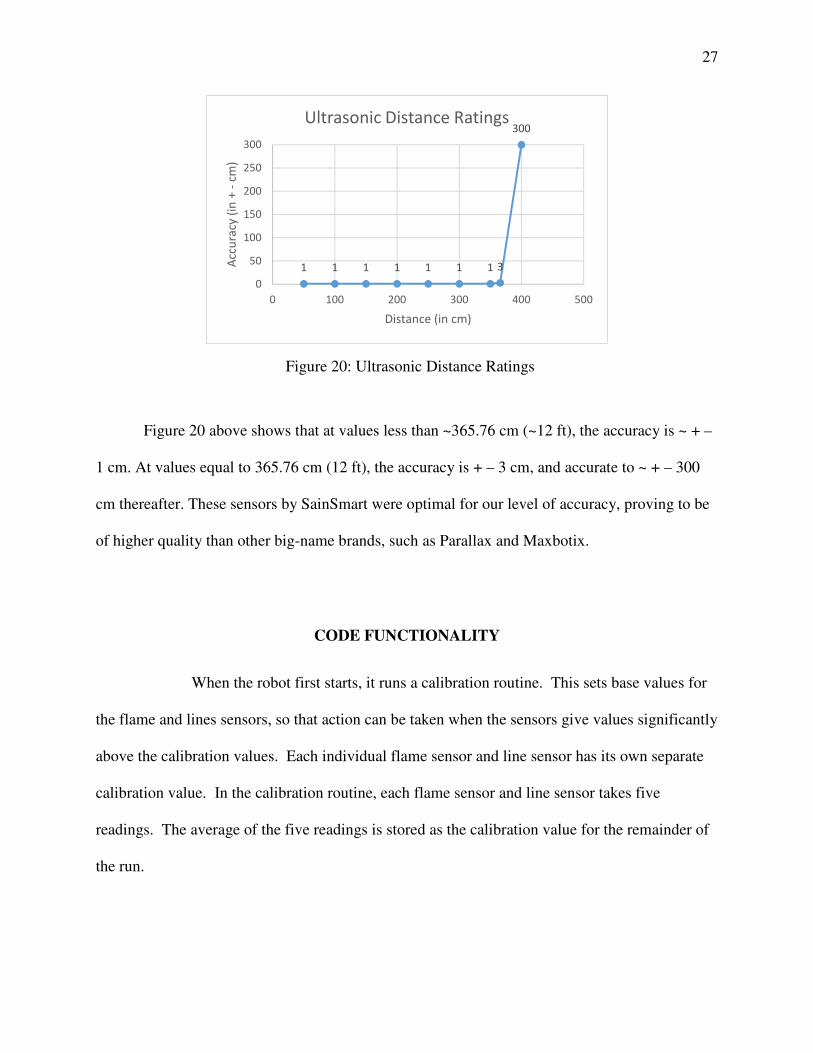
The ranging distance of this device was tested to be ~2 cm – 500 cm (0.5 ft – 16 ft.), accurate up
to ~ + – 1 cm. This accuracy is not applicable to larger distances, however, and tapers off, as
seen in Figure 20:
Figure 19: SainSmart Ultrasonic
Module HC-SR04 Distance Sensor
27
Figure 20 above shows that at values less than ~365.76 cm (~12 ft), the accuracy is ~ + –
1 cm. At values equal to 365.76 cm (12 ft), the accuracy is + – 3 cm, and accurate to ~ + – 300
cm thereafter. These sensors by SainSmart were optimal for our level of accuracy, proving to be
of higher quality than other big-name brands, such as Parallax and Maxbotix.
CODE FUNCTIONALITY
When the robot first starts, it runs a calibration routine. This sets base values for
the flame and lines sensors, so that action can be taken when the sensors give values significantly
above the calibration values. Each individual flame sensor and line sensor has its own separate
calibration value. In the calibration routine, each flame sensor and line sensor takes five
readings. The average of the five readings is stored as the calibration value for the remainder of
the run.
1 1 1 1 1 1 1 3
300
0
50
100
150
200
250
300
0 100 200 300 400 500
Acc
ura
cy (
in +
-cm
)
Distance (in cm)
Ultrasonic Distance Ratings
Figure 20: Ultrasonic Distance Ratings
28
After calibrating, the robot begins its search algorithm. Our current search algorithm has
our robot “ping pong” around the field, traveling in random directions until it finds a candle.
Despite the randomness, this algorithm has proven consistently able to find all four candles
within three minutes. The robot drives forward until told otherwise. When a flame sensor finds
a candle, it deviates from its search algorithm to extinguish it, as will be described later. When a
line sensor detects a black line, the robot moves backward a short distance before turning 135
degrees and driving forward. The backward motion is to prevent the robot from becoming stuck
on the line or going past it. If the proximity sensors detect a wall or extinguished candle within
25 cm, the robot turns 45 degrees in the direction with the most open space. In addition, the
robot backs up a short distance and resumes going forward if it has gone too long without
another action. This is done to prevent it from becoming stuck on walls that were out of view
from the proximity sensors, such as on the flame sensor support.
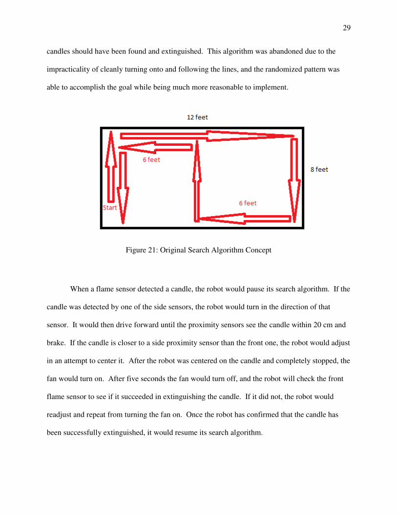
Our original attempt at a search algorithm used a more structured and methodical
approach. Under this algorithm, the robot would have first driven forward until reaching the first
candle, which was stated to always be placed within sight of the robot’s starting position.
Afterwards, the robot would turn away from the candle and drive until reaching the boundary
line. It would turn onto this line and follow it until reaching the corner. It would then follow this
line to the next corner, recording the distance traveled with the motor encoders. With this data, it
would know if the next line is an 8 foot line or a 12 foot line. If it is a 12 foot line, the robot
would drive 6 feet, turn right 90 degrees into the field, drive through the middle of the field, turn
left at the line on the other side, drive 6 feet to the corner, then follow the 8 foot line. If it is an 8
foot line instead, the robot would first follow this line and then execute the same pattern. After
completing this, all of the area of the field will have been seen by the flame sensors, so all four
candles should have been found and extinguished. This algorithm was abandoned due to the
impracticality of cleanly turning onto a
able to accomplish the goal while being much more reasonable to implement.
Figure 21
When a flame sensor detect
candle was detected by one of the side sensors, the robot
sensor. It would then drive forward until the proximity sensors see the candle within 20 cm and
brake. If the candle is closer to a side proximity sensor than the front one, the robot
in an attempt to center it. After the robot
fan would turn on. After five seconds the fan
flame sensor to see if it succeeded in extinguishing the candle. If it did not, the robot
readjust and repeat from turning th
been successfully extinguished, it
candles should have been found and extinguished. This algorithm was abandoned due to the
impracticality of cleanly turning onto and following the lines, and the randomized pattern was
able to accomplish the goal while being much more reasonable to implement.
21: Original Search Algorithm Concept
When a flame sensor detected a candle, the robot would pause its search algor
candle was detected by one of the side sensors, the robot would turn in the direction of that
then drive forward until the proximity sensors see the candle within 20 cm and
brake. If the candle is closer to a side proximity sensor than the front one, the robot
in an attempt to center it. After the robot was centered on the candle and completely stopped, the
turn on. After five seconds the fan would turn off, and the robot will check the front
flame sensor to see if it succeeded in extinguishing the candle. If it did not, the robot
readjust and repeat from turning the fan on. Once the robot has confirmed that the candle has
been successfully extinguished, it would resume its search algorithm.
29
candles should have been found and extinguished. This algorithm was abandoned due to the
nd following the lines, and the randomized pattern was
pause its search algorithm. If the
turn in the direction of that
then drive forward until the proximity sensors see the candle within 20 cm and
brake. If the candle is closer to a side proximity sensor than the front one, the robot would adjust
d completely stopped, the
turn off, and the robot will check the front
flame sensor to see if it succeeded in extinguishing the candle. If it did not, the robot would
that the candle has
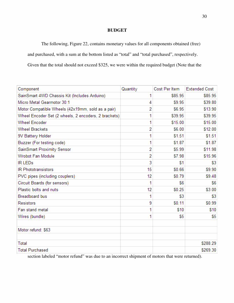
The following, Figure 22, contains monetary values for all components obtained (free)
and purchased, with a sum at the bottom listed
Given that the total should not exceed $325, we were within the required
section labeled “motor refund” was due to an incorrect shipment of motors that were returned).
BUDGET
, contains monetary values for all components obtained (free)
and purchased, with a sum at the bottom listed as “total” and “total purchased”, respectively.
Given that the total should not exceed $325, we were within the required budget (Note that the
ion labeled “motor refund” was due to an incorrect shipment of motors that were returned).
30
, contains monetary values for all components obtained (free)
, respectively.
budget (Note that the
ion labeled “motor refund” was due to an incorrect shipment of motors that were returned).
31
CONCLUSION
The project goals were completed in the time allotted and within the budget constraints.
The goals were to extinguish all four candles in under three minutes, and incorporate a custom-
built analog part. The robot’s best time for completing the challenge was 1:44, and it also utilized
not one, but two custom components: a flame sensor and a line sensor. Both components
provided useful data that kept the robot operating within the playing field and constantly in
search of lit candles.One drawback was the sudden rule change at RoboRave regarding playing
arenas and candle perimeters, but given the optimal performance by the robot in a lab
environment, this drawback was minimal.
REFERENCES
[1] Rohm Semiconductor Phototransistor 800nm 3mm datasheet. Copyright 2010. <http://www.digikey.com/product-search/en?lang=en&site=us&KeyWords=511-1358-ND&x=0&y=0> [2] EG&G Optoelectronics. Copyright 1997. <http://www.johnloomis.org/ece445/topics/egginc/pt_char.html>
Motor Driver, Robot Chassis, Microcontroller, and Ultrasonic Photos (Figures 4, 5, 6, and 19):
<http://www.sainsmart.com/robotics/sainsmart-uno-r3-4wd-gold-mobile-car-l298n-hc-sr04-kit-
for-arduino.html>
Motor Photo (Figure 7): <http://www.pololu.com/product/1093>
Encoder Photo (Figure 8): <http://www.pololu.com/product/1217>

32
PWM Signals Photo (Figure 9):
<http://upload.wikimedia.org/wikipedia/en/thumb/6/68/Quadrature_Diagram.svg/500px-
Quadrature_Diagram.svg.png>
Fan Photo (Figure 10):
<http://www.emartee.com/product/42252/Wrobot%20Fan%20Module%20For%20Fire%20Fight
ing%20Robot>