Embed Size (px)
Citation preview
8/12/2019 A Low-Speed, High-Torque, Direct-Drive Permanent Magnet Generator for Wind Turbine
http://slidepdf.com/reader/full/a-low-speed-high-torque-direct-drive-permanent-magnet-generator-for-wind 1/8
A Low-Speed, High-Torque, Direct-Drive Permanent Magnet Generator
For Wind Thrbines
w u V.S. Ramsden
CSIRO Telecommunications &Industrial Physics
PO Box 218, Lindfiled NSW 2070
Faculty of Engineering, UTSPO Box 123, Broadway
NSW 2007Australia Australia
T. Crawford, G. Hill
Westwind Turbines Pty Ltd29 Owen Road, Kelmscott
Western Australia 6 1 1Australia
Abstract-There is a market for small, efficient and cost-
effective wind generators for mini-grid and remote power
systems. Direct-drive permanent magnet generators havebecome very attractive for this application. This paper describes
the improvements achieved in an outer-rotor direct-drive
permanent magnet generator by using finite element analysisand optimisation techniques. The starting torque of thegenerator is studied. An optimisation routine for the design,including magnetic finite element analysis and lumped-
parameter thermal model, is presented. A prototype for 20 kW,211 rpm generator was built. The test results with a resistive
load confirm the satisfactory operation of the generator.Compared with the previous prototype, the new design haslower mass, lower starting torque and improved efficiency.
I. INTRODUCTION
Traditionally wind turbine generators have used gearboxes andpitch control to allow constant high-speed generation under varyingwind speed conditions. In recent years contemporary powerelectronics of high efficiency , high reliability and decreasing costoffers the option to change the power fi-equencyout of the generatorto match the system frequency, which leads to the idea of variablespeed direct-drive generators. A number of altemative concepts havebeen proposed for direct-drive electrical generators for use in grid-connected or stand-alone wind turbines [1,2]. Compared to a
conventional gearbox-coupled wind turbine generator, a directdrivegenerator has reduced overall size, lower installation andmaintenance cost, a flexible control method and quick response towind fluctuations and load variation.
A direct-drive generator must be light and efficient to minimisethe requirements for the tower structure and to maximise elecmcalpower extracted fkom the wind. For small wind turbines, directdrivepermanent magnet generators have become very attractive becauseof their high efficiency, high power density and robust rotorstructure. The attractiveness of direct-drive permanent magnetgenerators is further enhanced by improvements of permanentmagnet characteristics and decrease of material prices. Some direct-drive examplesare Enercon @ 12 ,30 kW), Proven (2.5 kw), LMW(2.5-10 kw ) and Venco-Westwind (2.5-10 kw ) [3].
A joint effort to develop a 20 kW low-speed, high-torque, direct-drive permanent magnet generator for wind turbines was initiated by
the University of Technology Sydney (UTS) and CommonwealthScientific and Industrial Research Organisation (CSIRO) in
conjunction with the Australian Cooperative Research Centre forRenewable Energy (ACRE) and Venco-Westwind. A non-optimised, 48-ple, 170 rpm prototype was constructed by Venco-
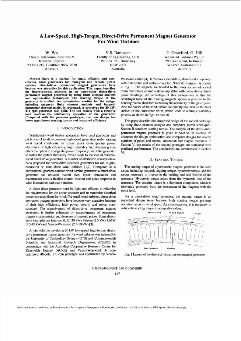
Westwind earlier [4]. It features a radial-flux, slotted-stator topologywth outer-rotor and surface-mounted Nd-Fe-B magnets, as shownin Fig. 1. The magnets are bonded to the inner surface of a steeldrumthat rotates around a stationary s tator with conventional three-phase windings. An advantage of this arrangement is that thecentrifugal force of the rotating magnets applies a pressure to thebond ing media, there fore increasing the reliability of the glued joint.Also the blades of the wind turb ine are directly mounted on the fi-Qnt
surface of the outer-rotor drumwhich leads to a simple assembly
process,as show n in Figs. 15 and 16.
This paper describes the improved design of the second prototypeby using finite element analysis and computer search techniques.Section II considers starting torque. The analys is of the direct-drivepermanent magnet generator is given in Section III. Section IVdiscusses the design optimisation and compares designs for severalnumbers of poles, and several lamination and magnet materials. In
Section V, test results of the second prototype are compared with
predicted perform ance. The conclus ions are summarised in SectionVI.
11. STARTINGORQUE
The starting torque of a permanent magnet generator is the totaltorque including the peak cogging torque, hysteresis torque, and thetorque necessary to overcome the bearing and seal friction of thegenerator. Hysteresis torque arises 6-om the hysteresis loss of thegenerator. The cogging torque is a dominent component, which‘isinherently generated from the interaction of the magnets with thestator teeth.
For a direct-drive wind generator, the starting torque is animportant design issue because high starting torque preventsoperation at cut-in wind speed. As a consequen ce, it is necessary toreduce the starting torque to accep table values.
Outer-rotord” N d - F e B magnets
Stator lanunalion Windings
Fig. 1 Layout of the direct-drivepermanent magnet generator
0-7803-6401-5/00/ 10.00 2000 IEEE
147
Authorized licensed use limited to: Reva Institute of Tehnology and Management. Downloaded on October 11, 2008 at 01:49 from IEEE Xplore. Restrictions apply.
8/12/2019 A Low-Speed, High-Torque, Direct-Drive Permanent Magnet Generator for Wind Turbine
http://slidepdf.com/reader/full/a-low-speed-high-torque-direct-drive-permanent-magnet-generator-for-wind 2/8
The cogging torque can be calculated directly for different rotorpositions, when the stator winding carries no current and theremanence of the magnet is known. Since the magnet remanence is
temperature dependent, the cogging torque varies with the operatingtemperature of the generator. The maximu m cogging torque occurs
when the rotor temperature is at room temperature.
The cogging torque is affected by ar gap length, slot wedgematerial, skew, magnet pole arc ratio, and slot opening width etc.For the first prototype, if the ar gap is increased from 1O mm to 1.4mm, the peak cogging torque is reduced from 62 .6 Nm to 26.0 Nm.
By using a mag netic slot wedge, the cogging torque can be reducedfurther from 26.0 Nm to 5.0Nm. Wh en the stator slot is skewed by
one tooth width as used in the first prototype, the peak coggingtorque decreases from 62.6 Nm to 11.8 Nm for an ar gap of 1.0
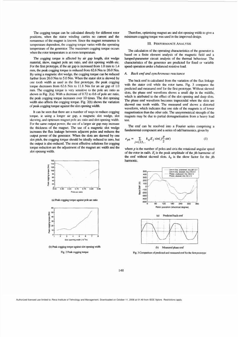
mm. The cogging torque is very sensitive to the pole arc ratio as
shown in Fig. 2(a). With a decrea se of 0.72 to 0.6 of pole arc ratio,
the peak cogging torque increases over 10 times. The slot openingwidth also affects the coggi ng torque. Fig. 2(b) shows the variationof peak cogging torque against the slot opening width.
It can be seen that there are a number of ways to reduce cogging
torque, ie using a longer air gap, a magnetic slot wedge, slotskewing, and optimum magnet pole arc ratio and slot opening width.For the same output power, the use of a larger ar gap may increase
the thickness of the magnet. The use of a magnetic slot wedgeincreases the flux leakage between adjacent poles and reduces theoutput power of the generator. When the slots are skewed by oneslot pitch, the cogging torque should be ideally reduced to zero, butthe output is also reduced. The most effective solutions for cogg ingtorque reduction are the adjustment of the magnet arc width and the
slot opening width.
= 100
8 40x
8 5 5 060 0 6 5 0 7 0 0 7 5 080 085
Pole arc rat io
Therefore, optimising magnet arc and slot opening width to give aminimu m cogging torque was used in the improved design.
111. PERFORMANCENALYSIS
The calculation of the operating characteristics of the generator isbased on a finite element analysis of the magnetic field and alumped-parameter circuit analysis of the thermal behaviour. Thecharacteristics of the generator are predicted for fixed or variable
speed operation under a balanced resistive load.
A. Back emf a nd synchrono us reactance
The back emf is calculated from the variation of the flux linkagewith the stator coil while the rotor turns. Fig. 3 compares the
predicted and measured emf for the first prototype. Without skewed
slots, the phase emf waveform shows a small dip in the middle,which is attributed to the effect of the slot opening and deep slots.
The phase emf waveform becomes trapezoidal when the slots areskewed one tooth width. The measured emf shows a distortedwaveform, which indicates that one side of the magnets is of lower
magnetisation than the o ther side. The unsymmetrical strength of themagnets may be due to partial demagnetisation from a heavy loadtest.
The emf can be resolved into a Fourier series comprising a
fundamental comp onent and a series of odd harmonics, given by
where p is the number of poles and w s the rotational angular speed
of the rotor in r d s . .$ is the peak amp litude of th eJth harmonic of
the emf without skewed slots. ks is the skew factor for the t hharmonic.
Line lo line. unskewed, ms 87 2 V
Line lo line.skewed. ms 79 5 VPhase, unskewed, m 66 2 V
Phase, skewed. nns 161 4 V300
(a)Peak ogmg toqueagainstpole~ I Cmtio
0 60 I20 180 240 300 360
Rotor posistion (electricaldegree)
(b)Peakcogging oque againstslotopening width
Fig. 2 Peak ogging torque
(a) Wctedbackemf
@) Measuredphaseemf
Fig. 3Comparison ofpledicted and measuredemffor the firstprototype
148
Authorized licensed use limited to: Reva Institute of Tehnology and Management. Downloaded on October 11, 2008 at 01:49 from IEEE Xplore. Restrictions apply.
8/12/2019 A Low-Speed, High-Torque, Direct-Drive Permanent Magnet Generator for Wind Turbine
http://slidepdf.com/reader/full/a-low-speed-high-torque-direct-drive-permanent-magnet-generator-for-wind 3/8
The synchronous reactance,X consists of the armaturereactanceand the leakage reactance. The armature reactance can be foundfrom incremental finite element analysis [ 5 ] while the leakagereactance can be calculated by an em pirical formula.
In terms of the phase emf, eph ynchronous reactance, X,, andphase resistance, R,, the generator can be represented by anequivalent circuit on a per-phase basis. Thus, for a star-connected 3-
phase symmetric resistive load, the load cu rrent, iph s derived from
where
and R, s the load resistance per phase.
Thus, therms value of the load current is
I =/-T-qG=1 5 7 1
(3)
(4)
B. Losses and load characteristics
The losses which affect the efficiency of the generator are thewinding copper loss, stator core loss, mechanical loss predominantlyfrom bearing and seal friction, and stray loss, due to eddy current
losses in the winding and magnets.
The copper loss, pa, s the principal loss in the generator under
most operating conditions. It can readily be calculated from thewinding resistance at the operating temperature, and is given by
Assuming a uniform sinusoidal flux density in the lamination, thecore loss,pR,can be expressed as
where p s the classical hysteresis loss, p c he classical eddy currentloss and pa he anomalous loss. These are given by
(7)
where k k and k, are the specific hysteresis, eddy current, and
anomalous losses, respectively, when the peak flux density Bpi. is 1T
and the frequencyfis 50Hz.W is the lamination mass. The corelosses in the stator ooth and yoke are calculated separately.
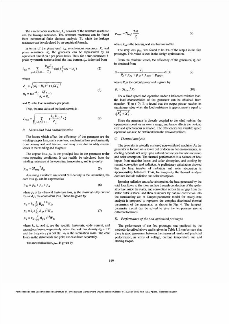
The mechanical loss,pmeos given by
-2
where Twis the bearing and seal friction in Nm.
The stray loss,pm was found to be 3% of the output in the first
prototype. This value is used in the design optimisation.
be obtained fromFrom the resultant losses, the efficiency of the generator, q can
X I 0 0O
Po + ~ c u P f e + P m e c + Pstray11=
where Po s the output power and isgiven by
(9)
For a fixed speed and operation under a balanced resistive load,
the load characteristics of the generator can be obtained fromequation (4) to (10). It is found that the output power reaches its
maximum value when the load resistance is approximately equal toJR, +X: .
Since the generator is directly coupled to the wind turbine, theoperational speed varies over a range, and hence affects the no-load
emf and synchronous reactance. The efficiencies for variable speedoperation can also be obtained &om the above equations.
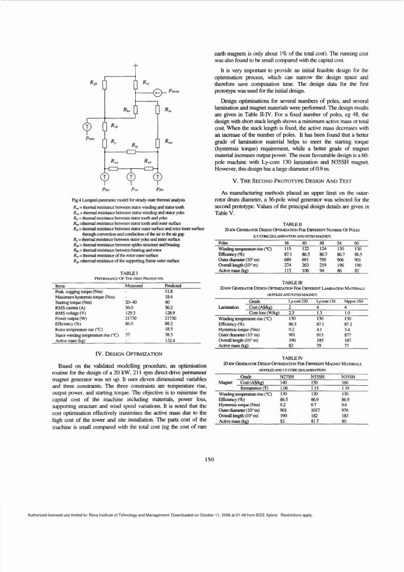
C Thermal analysis
The generator is a totally enclosed non-ventilated machine. As the
generator is located on a tower out of doors in hot environments, itscooling depends not only upon natural convection but also radiationand so lar absorption. The thermal performance is a balance of heat
inputs from machine losses and solar absorption, and cooling by
natural convection and radiation. A preliminary calculation showedthat the heat transfer of radiation and solar absorption is
approximately balanced. Thus or simplicity the thermal analysis
does no t include radiation and sola absorption.
Ignoring radiation and so lar absorption , the heat generated by thetotal loss flows to the rotor surface through conduction of the spiderstructure inside the stator, and convection ac ross the ar gap from the
stator outer surface, and then dissipates by natural convection intothe surrounding ar. A lumped-parameter model for steady-state
analysis is proposed to represent the complex distributed thermalparameters of the generator, as shown in Fig. 4. The lumped-parameter circuit can be solved to give the temperature rise atdifferent locations.
D. Performance of the non-optimised prototype
The performance of the first prototype was predicted by the
methods described above and is given in Table I It can be seen thatthere is good agreement between the measured results and predicted
performance, in terms of voltage, current, temperature rise andstarting torque.
149
Authorized licensed use limited to: Reva Institute of Tehnology and Management. Downloaded on October 11, 2008 at 01:49 from IEEE Xplore. Restrictions apply.
8/12/2019 A Low-Speed, High-Torque, Direct-Drive Permanent Magnet Generator for Wind Turbine
http://slidepdf.com/reader/full/a-low-speed-high-torque-direct-drive-permanent-magnet-generator-for-wind 4/8
earth magnets is only about 1% of the total cost). The running costwas also found to be small compared with the capital cost.
It is very important to provide an initial feasible design for the
optimisation process, which can nmow the design space andtherefore save computation time. The design data for the firstprototype was used for the initial design.
Design optimisations for several numbers of poles, and severallamination and magnet materials were p erformed. The design resultsare given in Table II-IV. For a fixed number of poles, eg 48, the
design with short stack length shows a minimum active mass or totalcost. When the stack length is fixed, the active mass decreases with
an increase of the number of poles. It has been found that a bettergrade of lamination material helps to meet the starting torque
(hysteresis torque) requirement, while a better grade of magnetmaterial increases output power. T he m ost favourable design is a 60-
pole machine with Ly-core 130 lamination and N35SH magnet.However, this design has a large diameter of 0.9 m.
V. THESECONDROTOTYPE ESIGNANDTEST
i
Pfev P c u Pfer
Rg.4hmped-pammeter model for steady-state hermal analysis
R =thermal resistance W e e n statorwindug and stator oothR = hermal resistance between statorwindmgand stator yokeR = hermal resistance between stator ooth and yokeRe =thermalresistancebetween stator ooth and outer surfaceRs= h d esist ncebetween statorouter surface ndrotor nner surface
Ry herm l resistancebetween tator yoke andinnersurface
Rb herm l resistance etween spidershucture ndbexing
Rb= therm l resistance between bearingand rotorR =thermalmistanceof the rotor outer surfaceRa =thermal resistanceof the supportingf r meouter surface
through convection and conduction of theair in the air gap
tem Measured predictedPeak cogging toque ( ) 11.8
~~ ~ ~
Maximumhysteresis oque (Nm)Startingtoque ( )
R MS cunent (A)RMS voltage(v)Power output (w)
Efficiency (%)
Rotor teqxrakue rise( C)
Stator windmg tempemture rise( C)Active mass kg)
18.420-40 40
56.0 56.2129.3 128.921730 2173086.0 88.2
18.5
57 58.5
132.4
IV. DESIGN PTIMIZATION
Based on the validated modelling procedure, an optimisationroutine for the design of a 20 kW, 211 'pm directdrive permanentmagnet generator was set up. It uses eleven dimensional variables
and three consb-aints. The three constraints are temperature rise,output power, and starting torque. The objective is to minimise the
capital cost of the machine including materials, power loss,supporting structure and wind speed variations. It is noted that the
cost optimisation effectively minimises the active mass due to the
high cost of the tower and site installation. The parts cost of the
machine is small compared with the total cost (eg the cost of rare
As manufacturing methods placed an upper limit on the outer-rotor drumdiameter, a 36-pole wind generator was selected for thesecond prototype. Values o f the principal design detads are given inTable V.
TABLE Il
20 KW GENERATORDE~IGNP I IM IZA~ON OR IFFE" NWEX OFPOLES
(LYCORE220LAMINATIONAND NDSH MAGNET)
Poles 3 6 4 0 4 8 5 4 6 0
W & ~ ~ r i s e ( C ) 115 122 124 130 130
EfficiGy (%) 87.1 86.5 86.7 86.7 86.5Outerdiameter(1OI m) 689 691 795 906 901Overall lengh lo3 ) 274 263 219 1% 190Activemass (kg) 115 106 94 86 82
TABLEm
~ ~ A N D N ~ S H M A G ~20Kw " E U l O R DESIGN OFTMlZ4TION FORDrmRwr ~ M N A T I O N A7ERMl.5
Glade Ly-core220 Ly-core I30 Nippon 35H
lamination Cost(A$/kg) 2 4 4
Core loss (W kg) 2.5 1.3 1 o
windingtemp ise ("C) 130 130 130
Efficieflcy (%) 86.5 87.1 87.2Hystensis oqu e (Nm) 9.2 4.1 3.4~u t e r d i a m e t e r ( i ~ m ) 901 913 877Overall length (IO' m) 190 185 187Active mass kg) 82 79 77
Grade N27SH N33SH N35SH
Re me nc e(T ) 1.06 1.15 1.19
W m z emperat urerise ("C) 130 130 130
Magnet Cmt(A$/kg) 140 150 160
Efficien.Cy(%) 86.5 86.9 86.9Hystemis toque (Nm) 9.2 9.7 9.6Outerdiameter(l0Im) 901 1017 976
Overall length (IO'm) 190 182 183Active mass kg) 82 81.7 80
150
Authorized licensed use limited to: Reva Institute of Tehnology and Management. Downloaded on October 11, 2008 at 01:49 from IEEE Xplore. Restrictions apply.
8/12/2019 A Low-Speed, High-Torque, Direct-Drive Permanent Magnet Generator for Wind Turbine
http://slidepdf.com/reader/full/a-low-speed-high-torque-direct-drive-permanent-magnet-generator-for-wind 5/8
Rotor position (mechanical degree)
Fig.5 Coggingtoque as a functionof rotor position
TABLE V
h l?CPAL D LSlGN DETlAISOFTHE SECONOPRoToT(pE
Number of poles
Number ofphases
outerdiameter
Overall axial len@
Laminatonmaterial
Magnetmaterial
Magnet thickness
Active mass
Resistance er phase at 20 C
Synchronousinductanceper phase
Synchronousreactance t 21 1 rpm
No-load phaseemf
Voltage at 20kW outputCurrentat 20k W utput
Efficiency at 20kW output
Maximumpower output at21 1 pm
36
3
610"
298 mm1.6"
Lycore 22N35SH Nd-k-B
3.5mm
0.1764 24.48mH
1.783 2209V
189 V35.1 A
91.6 %
28.1kW
112kg
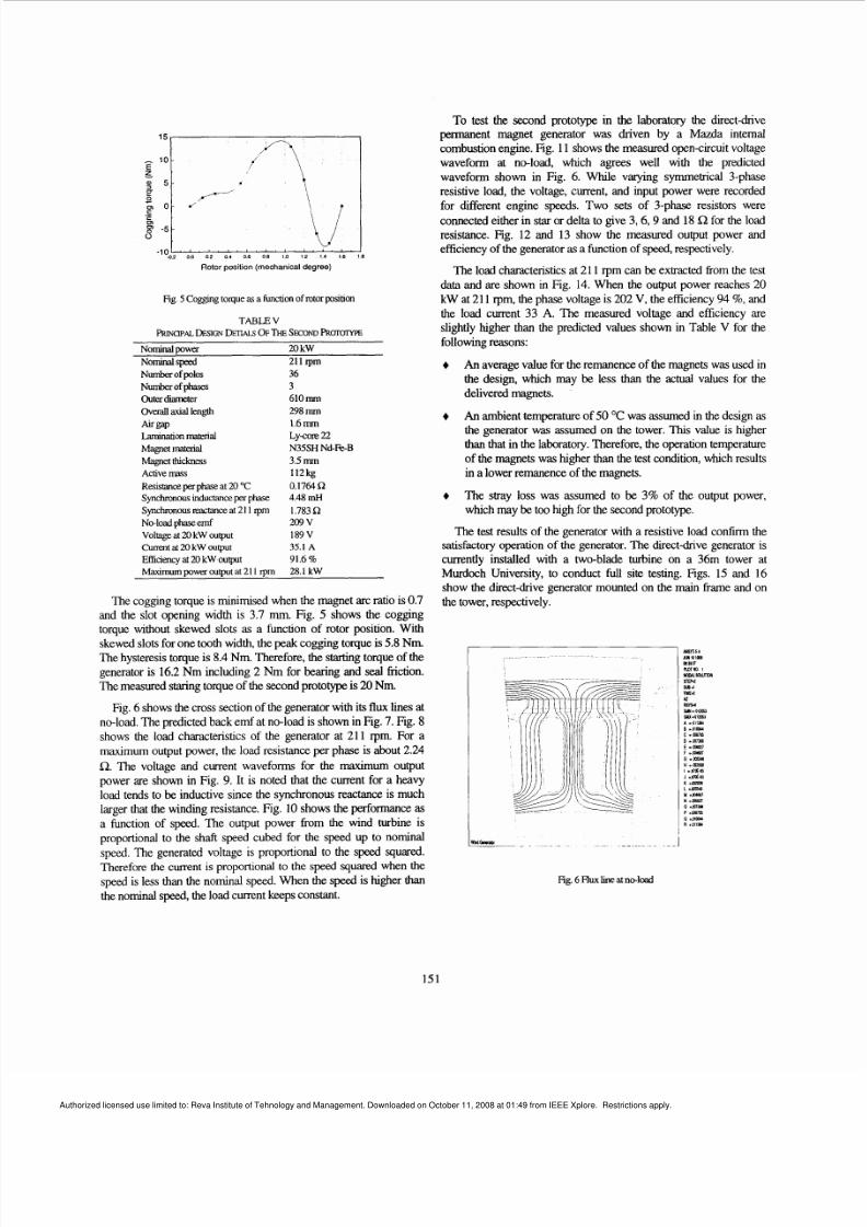
The cogging torque is minimised when the m agnet arc ratio is 0.7
and the slot opening width is 3.7 mm. Fig. 5 shows the coggingtorque without skewed slots as a function of rotor position. Withskewed slots for one tooth wid th, the peak cogging torque is 5.8 Nm.The hysteresis torque is 8.4 Nm. T herefore , the starting torque of thegenerator is 16.2 Nm including 2 Nm for bearing and seal iiiction.The measured staring o rque of the second prototype is20 Nm.
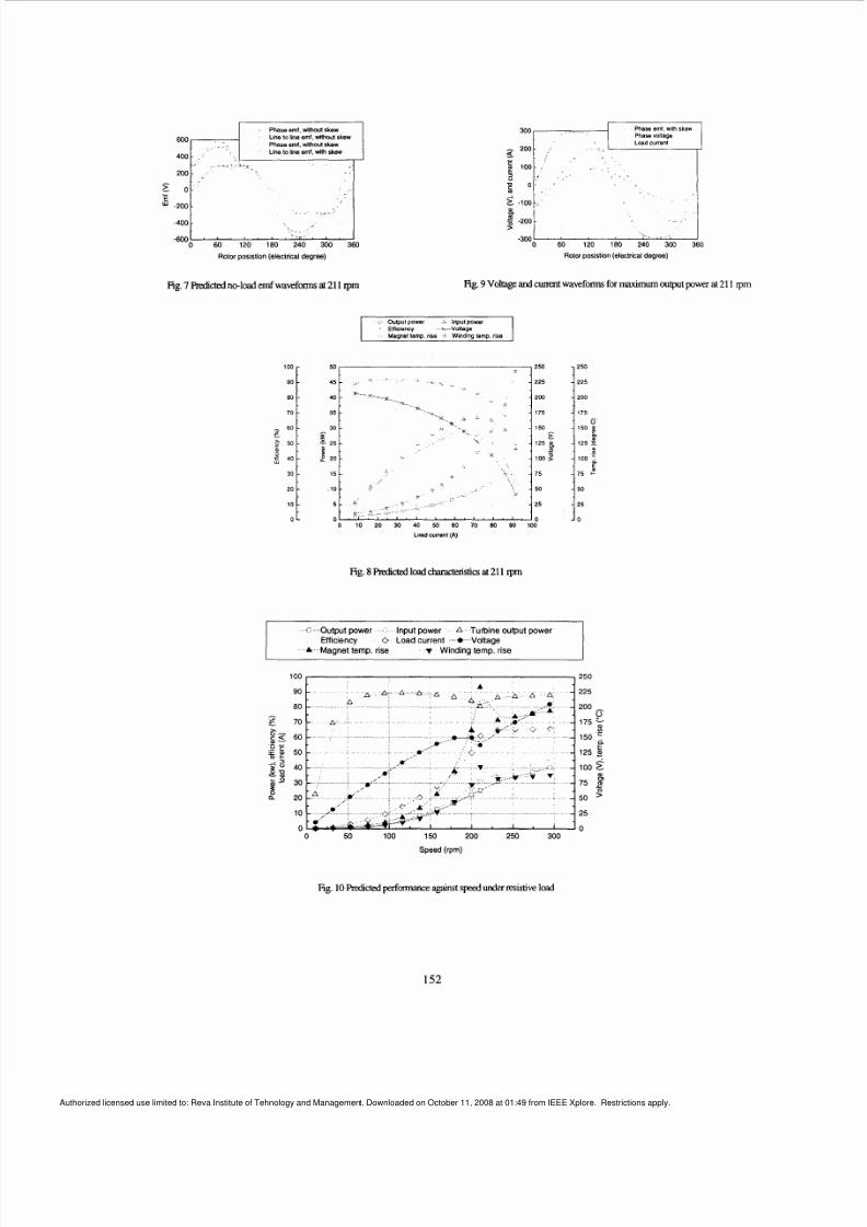
Fig. 6 shows the cross section of the gene rator with its flux lines atno-load. The predicted back emf at no-load is shown in Fig. 7.Fig. 8 shows the load characteristics of the generator at 211 rpm. For amaximum output pow er, the load resistance per phase is about 2.24
R. The voltage and current waveforms for the maximum outputpower are shown in Fig. 9. It is noted that the current for a heavyload tends to be inductive since the synchronous reactance is muchlarger that the winding resistance. Fig. 10 shows the performance as
a function of speed. The output power fiom the wind turbine isproportional to the shaft speed cubed for the speed up to nominalspeed. The generated voltage is proportional to the speed squared.Therefore the current is proportional to the speed squared when the
speed is less than the nominal speed. When the speed is higher than
the nominal speed, the load cur rent keeps constant.
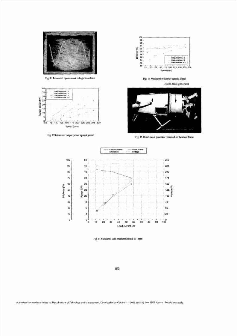
To test the second prototype in the laboratory the direct-drivepermanent magnet generator was driven by a Mazda intemalcombustion engine. Fig. 11 shows the measured open-circuit voltagewaveform at no-load, which agrees well with the predictedwaveform shown in Fig. 6. While varying symmetrical 3-phaseresistive load, the voltage, current, and input power were recorded
for different engine speeds. Two sets of 3-phase resistors wereconnected eithe r in star or delta to give 3 ,6 ,9 and 18 R or the loadresistance. Fig. 12 and 13 show the measured output power andefficiency of the generato ras a fun ction of speed, respectively.
The load characteristics at 21 1 rpm can be extracted kom the testdata and are shown in Fig. 14. When the output power reaches 20
kW at 21 1 rpm, the phase voltage is 202 V, the efficiency 94 %, andthe load current 33 A. The measured voltage and efficiency areslightly higher than the predicted values shown in Table V for thefollowing reasons:
An average value for the remanence of the magnets was used inthe design, which may be less than the actual values for thedelivered magnets.
An ambient temperature of 50 "C was assumed in the design as
the generator was assumed on the tower. This value is higherthan that in the laboratory. Therefo re, the operation temperatureof the magnets was higher than the test condition, which resultsin a lower remanence of the magnets.
The stray loss was assumed to be 3% of the output power,which may be too high for the second prototype.
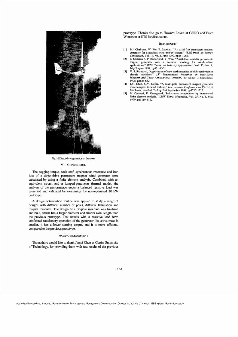
The test results of the generator with a resistive load conlirm thesatisfactory operation of the generator. The direct-drive generator is
currently installed with a two-blade turbine on a 36m tower atMurdoch University, to conduct full site testing. Figs. 15 and 16show the direct-drive generator mounted on the main kame and onthe to wer, respectively.
Fig.6Flux lineatno-load
151
Authorized licensed use limited to: Reva Institute of Tehnology and Management. Downloaded on October 11, 2008 at 01:49 from IEEE Xplore. Restrictions apply.
8/12/2019 A Low-Speed, High-Torque, Direct-Drive Permanent Magnet Generator for Wind Turbine
http://slidepdf.com/reader/full/a-low-speed-high-torque-direct-drive-permanent-magnet-generator-for-wind 6/8
Phase emf m thw t skew
Line lo line emf mthout skewPhase emf. m th w t skew
Line to line emf mth skew400
100
90
80
70
- 6 .
?3 5 0 -B .
4 0
30
20
to
0 -
200
400
6oo0 60 120 180 240 300 360
Rotor poststion ( e l e c l n ca l d e g re e )
-
-
--
-
-
-
Pham emf wlm Skew
Phasevoltage
Load current
100
-
-
-
--
-
1
-
-
-
-300; 60 1o reo 2hO 360 360
Rotor posistion (eleclreald e g re e )
250
225
200
175
50 p
125 BP
100:E
75
50
25
0
Fig. 7 Pmlictedno-load mf waveforms at 211 rpm Fig. 9Voltage and n t waveforms for maximumoutput poww at 211 tpm
-
-
-~-
-
, -
2w
175
153
125 $
->
1 0 0 2
Output power Input pawerEHlciemy +Voltage
Magnet temp me , Winding temp rise
50 250
' \ i 2255* *
x.. ... .x - . ...
35
1::I,;, , ~ ,, ; ,; , , , , , l5 l 25,-
n0 00 10 20 30 40 5 6 70 8 90 100
Load current (A)
Fig. 8predictedloadcharacteris icsat211 rpm
r Output power Input power A Turbine output power
Efficiency Loadcurrent + Voltage
Magnet temp. rise v Winding temp rise
225
200
175
150
125 E100 L
G
I
-75 550
25
00 50 100 150 200 250 300
Speed (rpm)
Fig. 10predict edpformance against speed under resistive load
152
Authorized licensed use limited to: Reva Institute of Tehnology and Management. Downloaded on October 11, 2008 at 01:49 from IEEE Xplore. Restrictions apply.
8/12/2019 A Low-Speed, High-Torque, Direct-Drive Permanent Magnet Generator for Wind Turbine
http://slidepdf.com/reader/full/a-low-speed-high-torque-direct-drive-permanent-magnet-generator-for-wind 7/8
Fig. 1I Measuredopen-circuitvoltage waveform
100
90
80
70
60E .6 5 0 -
P._
40
30
20
10
0
~ Load resistance9 L1
Lozd resistance 18n2
25
--
-
-
-
-
-
-
-
20
2 15
02 10
5
050 75 100 125 150 175 200 225 250 275 300
Speed (rpm)
Fig. 12Measuredoutput power againstspeed
Fig 13Measured efficiencyagainstspeed
Direct-drive generatoiI
Fig. 15 Direct-drivegeneratorm t e d n tbe main fmne
- -Output power * Inputpower
Effciency ---Voltage
00 10 20 30 40 50 60 70 80 90 100
Load current (A)
Fig. 14Measuxd load chamcteristicsat 211 rpm
153
Authorized licensed use limited to: Reva Institute of Tehnology and Management. Downloaded on October 11, 2008 at 01:49 from IEEE Xplore. Restrictions apply.
8/12/2019 A Low-Speed, High-Torque, Direct-Drive Permanent Magnet Generator for Wind Turbine
http://slidepdf.com/reader/full/a-low-speed-high-torque-direct-drive-permanent-magnet-generator-for-wind 8/8
prototype. Thanks also go to Howard Lovatt at CSIRO and PeterWatterson at UTS for discussions.
REFERENCES
[ I ] B.J. Chalmers, W. Wu, E. Spooner, “An axial-flux permanent-magnetgenerator for a gearless wind energy system,” IEEE trans. o Energy
Conversion Vol. 14, No. 2, June 1999,pp251-257.E. Muljada, C.P. Butterfield, Y. Wan, “Axial-flux modular permanent-magnet generator with a toroidal winding for wind-turbineapplications,” IEEE Trans. on Industry Applications Vol. 35, No. 4,
July/August 1999,pp831-836.V. S. Ramsden, “Application of rare-earth magnets in high-performanceelectric machines,” 15‘‘ International Workshop on Rare-EurthMagnets and Their Applications Dresden, 30 August-3 September,
J.Y. Chen, C.V. Nayar, “A multi-pole permanent magnet generatordirect coupled to wind turbine,” International Conference on Electrical
Machines Istanbul, Turkey, 2-4 September 1998,pp1717-1722.M. Gyimesi, D. Ostergaard, “Inductance computation by incrementalfinite element analysis,’’ IEEE Trans. Magnetics Vol. 35, No. 3, May
[2]
[3]
1998,~ ~ 6 2 3 - 6 4 2 .
[4]
[5]
1999,~ ~ 1 1 1 9 - 1 1 2 2 .
Fig. 16k t d i v e eneratoronthe ower
VI. CONCLUSION
The cogging torque, back emf, synchronous reactance and ironloss of a direct&ve permanent magnet wind generator werecalculated by using a finite element analysis. Combined with anequivalent circuit and a lumped-parameter thermal model, theanalysis of the performance under a balanced resistive load waspresented and validated by examining the non-optimised 20 kW
prototype.
A design optimisation routine was applied to study a range ofdesigns with different number of poles, different lamination andmagnet materials. The design of a 36-pole machine was finalised
and built, which has a larger diameter and shorter axial length thanthe previous prototype. Test results with a resistive load haveconfirmed satisfactory operation of the generator. Its active mass issmaller, it has a lower starting torque, and it is more efficient,compared to the previous prototype.
ACKNOWLEDGMENT
The authors would like to thankJianyi Chen at Curtin University
of Technology, for providing them with test results of the previous
154


![Torque Characteristic Analysis of a Transverse Flux Motor ... · PDF filethe permanent magnet vernier motor (PMVM) [3–5] and the transverse flux motor ... The permanent magnet flux](https://img.pdfslide.net/doc/110x75/5aafa58d7f8b9a6b308d8f9f/torque-characteristic-analysis-of-a-transverse-flux-motor-permanent-magnet-vernier.jpg)