Embed Size (px)
Citation preview
2674 IEEE TRANSACTIONS ON INDUSTRIAL ELECTRONICS, VOL. 55, NO. 7, JULY 2008
A Maximum Power Point Tracking SystemWith Parallel Connection for PV
Stand-Alone ApplicationsRoger Gules, Juliano De Pellegrin Pacheco, Hélio Leães Hey, Member, IEEE, and Johninson Imhoff
Abstract—This paper presents the analysis, design, and imple-mentation of a parallel connected maximum power point tracking(MPPT) system for stand-alone photovoltaic power generation.The parallel connection of the MPPT system reduces the negativeinfluence of power converter losses in the overall efficiency becauseonly a part of the generated power is processed by the MPPTsystem. Furthermore, all control algorithms used in the classicalseries-connected MPPT can be applied to the parallel system.A simple bidirectional dc–dc power converter is proposed forthe MPPT implementation and presents the functions of batterycharger and step-up converter. The operation characteristics ofthe proposed circuit are analyzed with the implementation of aprototype in a practical application.
Index Terms—DC–DC power conversion, photovoltaic (PV)power systems, solar energy.
I. INTRODUCTION
THE CONTINUOUS growth of the global energy demandassociated with society’s increasing awareness of envi-
ronmental impacts from the widespread utilization of fossilfuels has led to the exploration of renewable energy sources,such as photovoltaic (PV) technology. Although PV energy hasreceived considerable attention over the last few decades, thehigh installation cost of PV systems and the low conversion effi-ciency of PV modules are the major obstacles to using this alter-native energy source on a large scale. Therefore, several studiesare being developed in order to minimize these drawbacks[1]–[9]. In order to extract the maximum power of the PVarray, the classical implementation of the maximum powerpoint tracking (MPPT) in stand-alone systems is generallyaccomplished by the series connection of a dc–dc converter be-tween the PV array and the load or the energy storage element.Considering that in the series connection, the dc–dc converteralways processes all power generated, the total efficiency of thePV system greatly depends on the efficiency of this series dc–dcconverter. As an alternative to this configuration, this paperpresents an MPPT system based on the parallel connection ofa dc–dc converter. With this configuration, only a part of the
Manuscript received September 26, 2007; revised March 31,2008. This workwas supported by Fundação Araucária under Grant 10966.
R. Gules and J. D. P. Pacheco are with the Federal University of TechnologyCPGEI-UTFPR, 80230-901 Curitiba, Brazil (e-mail: [email protected]).
H. L. Hey is with the Power Electronics and Control Research Group, FederalUniversity of Santa Maria, Santa Maria 97105-900, Brazil.
J. Imhoff is with the Electrolux do Brazil S.A., Curitiba 81520-900, Brazil.Digital Object Identifier 10.1109/TIE.2008.924033
energy generated is processed by the dc–dc converter, makingit possible to obtain an increase in the total efficiency of the PVsystem as compared with the series configuration.
The operation principle, theoretical analysis, design method-ology, and experimental results of a laboratory prototype of theparallel MPPT system are presented in this paper.
II. MPPT IN STAND-ALONE PV SYSTEMS
A. Solar Cell Output Characteristic
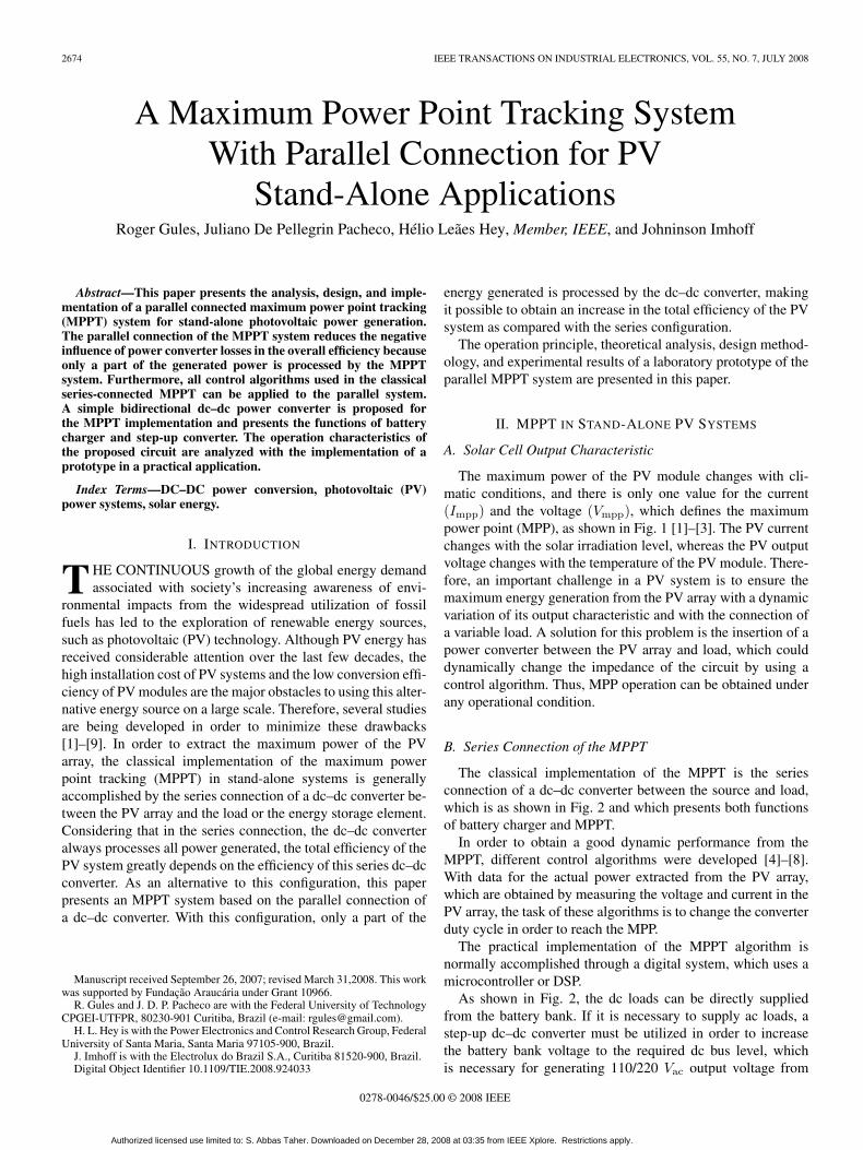
The maximum power of the PV module changes with cli-matic conditions, and there is only one value for the current(Impp) and the voltage (Vmpp), which defines the maximumpower point (MPP), as shown in Fig. 1 [1]–[3]. The PV currentchanges with the solar irradiation level, whereas the PV outputvoltage changes with the temperature of the PV module. There-fore, an important challenge in a PV system is to ensure themaximum energy generation from the PV array with a dynamicvariation of its output characteristic and with the connection ofa variable load. A solution for this problem is the insertion of apower converter between the PV array and load, which coulddynamically change the impedance of the circuit by using acontrol algorithm. Thus, MPP operation can be obtained underany operational condition.
B. Series Connection of the MPPT
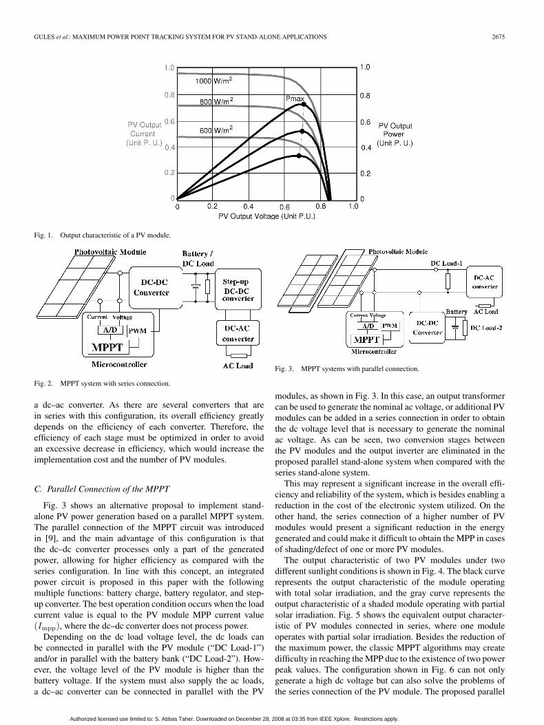
The classical implementation of the MPPT is the seriesconnection of a dc–dc converter between the source and load,which is as shown in Fig. 2 and which presents both functionsof battery charger and MPPT.
In order to obtain a good dynamic performance from theMPPT, different control algorithms were developed [4]–[8].With data for the actual power extracted from the PV array,which are obtained by measuring the voltage and current in thePV array, the task of these algorithms is to change the converterduty cycle in order to reach the MPP.
The practical implementation of the MPPT algorithm isnormally accomplished through a digital system, which uses amicrocontroller or DSP.
As shown in Fig. 2, the dc loads can be directly suppliedfrom the battery bank. If it is necessary to supply ac loads, astep-up dc–dc converter must be utilized in order to increasethe battery bank voltage to the required dc bus level, whichis necessary for generating 110/220 Vac output voltage from
0278-0046/$25.00 © 2008 IEEE
Authorized licensed use limited to: S. Abbas Taher. Downloaded on December 28, 2008 at 03:35 from IEEE Xplore. Restrictions apply.
GULES et al.: MAXIMUM POWER POINT TRACKING SYSTEM FOR PV STAND-ALONE APPLICATIONS 2675
Fig. 1. Output characteristic of a PV module.
Fig. 2. MPPT system with series connection.
a dc–ac converter. As there are several converters that arein series with this configuration, its overall efficiency greatlydepends on the efficiency of each converter. Therefore, theefficiency of each stage must be optimized in order to avoidan excessive decrease in efficiency, which would increase theimplementation cost and the number of PV modules.
C. Parallel Connection of the MPPT
Fig. 3 shows an alternative proposal to implement stand-alone PV power generation based on a parallel MPPT system.The parallel connection of the MPPT circuit was introducedin [9], and the main advantage of this configuration is thatthe dc–dc converter processes only a part of the generatedpower, allowing for higher efficiency as compared with theseries configuration. In line with this concept, an integratedpower circuit is proposed in this paper with the followingmultiple functions: battery charge, battery regulator, and step-up converter. The best operation condition occurs when the loadcurrent value is equal to the PV module MPP current value(Impp), where the dc–dc converter does not process power.
Depending on the dc load voltage level, the dc loads canbe connected in parallel with the PV module (“DC Load-1”)and/or in parallel with the battery bank (“DC Load-2”). How-ever, the voltage level of the PV module is higher than thebattery voltage. If the system must also supply the ac loads,a dc–ac converter can be connected in parallel with the PV
Fig. 3. MPPT systems with parallel connection.
modules, as shown in Fig. 3. In this case, an output transformercan be used to generate the nominal ac voltage, or additional PVmodules can be added in a series connection in order to obtainthe dc voltage level that is necessary to generate the nominalac voltage. As can be seen, two conversion stages betweenthe PV modules and the output inverter are eliminated in theproposed parallel stand-alone system when compared with theseries stand-alone system.
This may represent a significant increase in the overall effi-ciency and reliability of the system, which is besides enabling areduction in the cost of the electronic system utilized. On theother hand, the series connection of a higher number of PVmodules would present a significant reduction in the energygenerated and could make it difficult to obtain the MPP in casesof shading/defect of one or more PV modules.
The output characteristic of two PV modules under twodifferent sunlight conditions is shown in Fig. 4. The black curverepresents the output characteristic of the module operatingwith total solar irradiation, and the gray curve represents theoutput characteristic of a shaded module operating with partialsolar irradiation. Fig. 5 shows the equivalent output character-istic of PV modules connected in series, where one moduleoperates with partial solar irradiation. Besides the reduction ofthe maximum power, the classic MPPT algorithms may createdifficulty in reaching the MPP due to the existence of two powerpeak values. The configuration shown in Fig. 6 can not onlygenerate a high dc voltage but can also solve the problems ofthe series connection of the PV module. The proposed parallel
Authorized licensed use limited to: S. Abbas Taher. Downloaded on December 28, 2008 at 03:35 from IEEE Xplore. Restrictions apply.
2676 IEEE TRANSACTIONS ON INDUSTRIAL ELECTRONICS, VOL. 55, NO. 7, JULY 2008
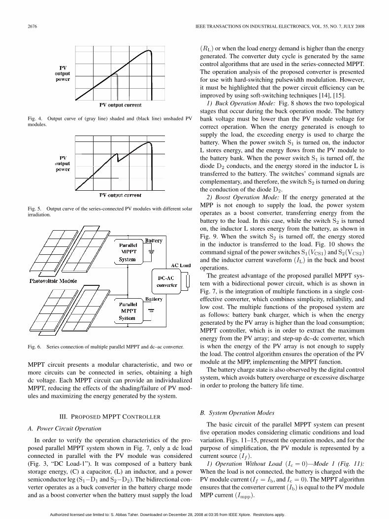
Fig. 4. Output curve of (gray line) shaded and (black line) unshaded PVmodules.
Fig. 5. Output curve of the series-connected PV modules with different solarirradiation.
Fig. 6. Series connection of multiple parallel MPPT and dc–ac converter.
MPPT circuit presents a modular characteristic, and two ormore circuits can be connected in series, obtaining a highdc voltage. Each MPPT circuit can provide an individualizedMPPT, reducing the effects of the shading/failure of PV mod-ules and maximizing the energy generated by the system.
III. PROPOSED MPPT CONTROLLER
A. Power Circuit Operation
In order to verify the operation characteristics of the pro-posed parallel MPPT system shown in Fig. 7, only a dc loadconnected in parallel with the PV module was considered(Fig. 3, “DC Load-1”). It was composed of a battery bankstorage energy, (C) a capacitor, (L) an inductor, and a powersemiconductor leg (S1−D1 and S2−D2). The bidirectional con-verter operates as a buck converter in the battery charge modeand as a boost converter when the battery must supply the load
(RL) or when the load energy demand is higher than the energygenerated. The converter duty cycle is generated by the samecontrol algorithms that are used in the series-connected MPPT.The operation analysis of the proposed converter is presentedfor use with hard-switching pulsewidth modulation. However,it must be highlighted that the power circuit efficiency can beimproved by using soft-switching techniques [14], [15].1) Buck Operation Mode: Fig. 8 shows the two topological
stages that occur during the buck operation mode. The batterybank voltage must be lower than the PV module voltage forcorrect operation. When the energy generated is enough tosupply the load, the exceeding energy is used to charge thebattery. When the power switch S1 is turned on, the inductorL stores energy, and the energy flows from the PV module tothe battery bank. When the power switch S1 is turned off, thediode D2 conducts, and the energy stored in the inductor L istransferred to the battery. The switches’ command signals arecomplementary, and therefore, the switch S2 is turned on duringthe conduction of the diode D2.
2) Boost Operation Mode: If the energy generated at theMPP is not enough to supply the load, the power systemoperates as a boost converter, transferring energy from thebattery to the load. In this case, while the switch S2 is turnedon, the inductor L stores energy from the battery, as shown inFig. 9. When the switch S2 is turned off, the energy storedin the inductor is transferred to the load. Fig. 10 shows thecommand signal of the power switches S1(VCS1) and S2(VCS2)and the inductor current waveform (IL) in the buck and boostoperations.
The greatest advantage of the proposed parallel MPPT sys-tem with a bidirectional power circuit, which is as shown inFig. 7, is the integration of multiple functions in a single cost-effective converter, which combines simplicity, reliability, andlow cost. The multiple functions of the proposed system areas follows: battery bank charger, which is when the energygenerated by the PV array is higher than the load consumption;MPPT controller, which is in order to extract the maximumenergy from the PV array; and step-up dc–dc converter, whichis when the energy of the PV array is not enough to supplythe load. The control algorithm ensures the operation of the PVmodule at the MPP, implementing the MPPT function.
The battery charge state is also observed by the digital controlsystem, which avoids battery overcharge or excessive dischargein order to prolong the battery life time.
B. System Operation Modes
The basic circuit of the parallel MPPT system can presentfive operation modes considering climatic conditions and loadvariation. Figs. 11–15, present the operation modes, and for thepurpose of simplification, the PV module is represented by acurrent source (If ).1) Operation Without Load (Ic = 0)—Mode 1 (Fig. 11):
When the load is not connected, the battery is charged with thePV module current (If = Ib, and Ic = 0). The MPPT algorithmensures that the converter current (Ib) is equal to the PV moduleMPP current (Impp).
Authorized licensed use limited to: S. Abbas Taher. Downloaded on December 28, 2008 at 03:35 from IEEE Xplore. Restrictions apply.
GULES et al.: MAXIMUM POWER POINT TRACKING SYSTEM FOR PV STAND-ALONE APPLICATIONS 2677
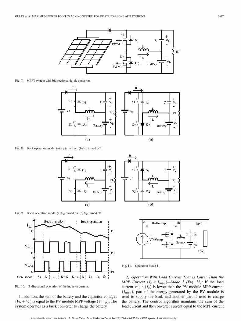
Fig. 7. MPPT system with bidirectional dc–dc converter.
Fig. 8. Buck operation mode. (a) S1 turned on. (b) S1 turned off.
Fig. 9. Boost operation mode. (a) S2 turned on. (b) S2 turned off.
Fig. 10. Bidirectional operation of the inductor current.
In addition, the sum of the battery and the capacitor voltages(Vb + Vc) is equal to the PV module MPP voltage (Vmpp). Thesystem operates as a buck converter to charge the battery.
Fig. 11. Operation mode 1.
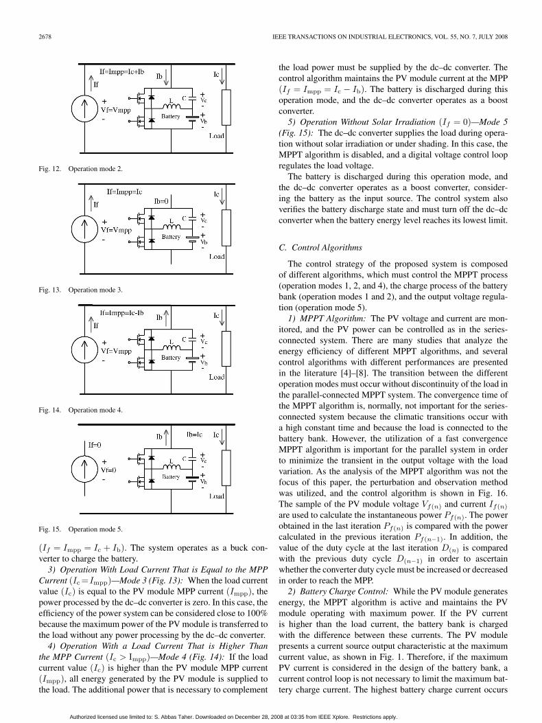
2) Operation With Load Current That is Lower Than theMPP Current (Ic < Impp)—Mode 2 (Fig. 12): If the loadcurrent value (Ic) is lower than the PV module MPP current(Impp), part of the energy generated by the PV module isused to supply the load, and another part is used to chargethe battery. The control algorithm maintains the sum of theload current and the converter current equal to the MPP current
Authorized licensed use limited to: S. Abbas Taher. Downloaded on December 28, 2008 at 03:35 from IEEE Xplore. Restrictions apply.
2678 IEEE TRANSACTIONS ON INDUSTRIAL ELECTRONICS, VOL. 55, NO. 7, JULY 2008
Fig. 12. Operation mode 2.
Fig. 13. Operation mode 3.
Fig. 14. Operation mode 4.
Fig. 15. Operation mode 5.
(If = Impp = Ic + Ib). The system operates as a buck con-verter to charge the battery.3) Operation With Load Current That is Equal to the MPP
Current (Ic =Impp)—Mode 3 (Fig. 13): When the load currentvalue (Ic) is equal to the PV module MPP current (Impp), thepower processed by the dc–dc converter is zero. In this case, theefficiency of the power system can be considered close to 100%because the maximum power of the PV module is transferred tothe load without any power processing by the dc–dc converter.4) Operation With a Load Current That is Higher Than
the MPP Current (Ic > Impp)—Mode 4 (Fig. 14): If the loadcurrent value (Ic) is higher than the PV module MPP current(Impp), all energy generated by the PV module is supplied tothe load. The additional power that is necessary to complement
the load power must be supplied by the dc–dc converter. Thecontrol algorithm maintains the PV module current at the MPP(If = Impp = Ic − Ib). The battery is discharged during thisoperation mode, and the dc–dc converter operates as a boostconverter.5) Operation Without Solar Irradiation (If = 0)—Mode 5
(Fig. 15): The dc–dc converter supplies the load during opera-tion without solar irradiation or under shading. In this case, theMPPT algorithm is disabled, and a digital voltage control loopregulates the load voltage.
The battery is discharged during this operation mode, andthe dc–dc converter operates as a boost converter, consider-ing the battery as the input source. The control system alsoverifies the battery discharge state and must turn off the dc–dcconverter when the battery energy level reaches its lowest limit.
C. Control Algorithms
The control strategy of the proposed system is composedof different algorithms, which must control the MPPT process(operation modes 1, 2, and 4), the charge process of the batterybank (operation modes 1 and 2), and the output voltage regula-tion (operation mode 5).1) MPPT Algorithm: The PV voltage and current are mon-
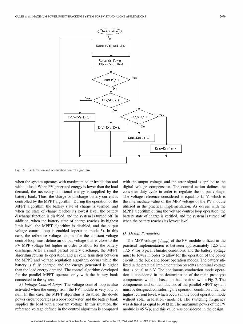
itored, and the PV power can be controlled as in the series-connected system. There are many studies that analyze theenergy efficiency of different MPPT algorithms, and severalcontrol algorithms with different performances are presentedin the literature [4]–[8]. The transition between the differentoperation modes must occur without discontinuity of the load inthe parallel-connected MPPT system. The convergence time ofthe MPPT algorithm is, normally, not important for the series-connected system because the climatic transitions occur witha high constant time and because the load is connected to thebattery bank. However, the utilization of a fast convergenceMPPT algorithm is important for the parallel system in orderto minimize the transient in the output voltage with the loadvariation. As the analysis of the MPPT algorithm was not thefocus of this paper, the perturbation and observation methodwas utilized, and the control algorithm is shown in Fig. 16.The sample of the PV module voltage Vf(n) and current If(n)
are used to calculate the instantaneous power Pf(n). The powerobtained in the last iteration Pf(n) is compared with the powercalculated in the previous iteration Pf(n−1). In addition, thevalue of the duty cycle at the last iteration D(n) is comparedwith the previous duty cycle D(n−1) in order to ascertainwhether the converter duty cycle must be increased or decreasedin order to reach the MPP.2) Battery Charge Control: While the PV module generates
energy, the MPPT algorithm is active and maintains the PVmodule operating with maximum power. If the PV currentis higher than the load current, the battery bank is chargedwith the difference between these currents. The PV modulepresents a current source output characteristic at the maximumcurrent value, as shown in Fig. 1. Therefore, if the maximumPV current is considered in the design of the battery bank, acurrent control loop is not necessary to limit the maximum bat-tery charge current. The highest battery charge current occurs
Authorized licensed use limited to: S. Abbas Taher. Downloaded on December 28, 2008 at 03:35 from IEEE Xplore. Restrictions apply.
GULES et al.: MAXIMUM POWER POINT TRACKING SYSTEM FOR PV STAND-ALONE APPLICATIONS 2679
Fig. 16. Perturbation and observation control algorithm.
when the system operates with maximum solar irradiation andwithout load. When PV-generated energy is lower than the loaddemand, the necessary additional energy is supplied by thebattery bank. Thus, the charge or discharge battery current iscontrolled by the MPPT algorithm. During the operation of theMPPT algorithm, the battery state of charge is verified, andwhen the state of charge reaches its lowest level, the batterydischarge function is disabled, and the system is turned off. Inaddition, when the battery state of charge reaches its highestlimit level, the MPPT algorithm is disabled, and the outputvoltage control loop is enabled (operation mode 5). In thiscase, the reference voltage adopted for the constant voltagecontrol loop must define an output voltage that is close to thePV MPP voltage but higher in order to allow for the batterydischarge. After a small partial battery discharge, the MPPTalgorithm returns to operation, and a cyclic transition betweenthe MPPT and voltage regulation algorithm occurs while thebattery is fully charged and the energy generated is higherthan the load energy demand. The control algorithm developedfor the parallel MPPT operates only with the battery bankconnected to the system.3) Voltage Control Loop: The voltage control loop is also
activated when the energy from the PV module is very low ornull. In this case, the MPPT algorithm is disabled, the dc–dcpower circuit operates as a boost converter, and the battery banksupplies the load with a constant voltage. In this situation, thereference voltage defined in the control algorithm is compared
with the output voltage, and the error signal is applied to thedigital voltage compensator. The control action defines theconverter duty cycle in order to regulate the output voltage.The voltage reference considered is equal to 15 V, which isthe intermediate value of the MPP voltage of the PV moduleutilized in the practical implementation. As occurs with theMPPT algorithm during the voltage control loop operation, thebattery state of charge is verified, and the system is turned offwhen the battery reaches its lowest level.
D. Design Parameters
The MPP voltage (Vmpp) of the PV module utilized in thepractical implementation is between approximately 12.5 and17.5 V for typical climatic conditions, and the battery voltagemust be lower in order to allow for the operation of the powercircuit in the buck and boost operation modes. The battery uti-lized in the practical implementation presents a nominal voltagethat is equal to 6 V. The continuous conduction mode opera-tion is considered in the determination of the main prototypecomponents, which is based on the circuit shown in Fig. 7. Thecomponents and semiconductors of the parallel MPPT systemmust be designed, considering the operation condition under thehighest current level, which occurs in the boost operation modewithout solar irradiation (mode 5). The switching frequencywas defined as equal to 30 kHz. The maximum power of the PVmodule is 45 Wp, and this value was considered in the design.
Authorized licensed use limited to: S. Abbas Taher. Downloaded on December 28, 2008 at 03:35 from IEEE Xplore. Restrictions apply.
2680 IEEE TRANSACTIONS ON INDUSTRIAL ELECTRONICS, VOL. 55, NO. 7, JULY 2008
1) Inductor: The average inductor current in the boost op-eration is defined by (1), considering an efficiency equal toη = 90%
IL =P
Vb · η =45
6 · 0.9= 8.333 A. (1)
A current ripple that is equal to 20% was considered in theinductance determination
∆I = 0.2 · IL = 0.2 · 8.333 = 1.667 A. (2)
The operation point defined is a duty cycle that is equal toD = 0.67, which is in order to obtain a load voltage that is equalto 18 V, with a battery voltage equal to 6 V. The inductance iscalculated by
L =Vin · Df · ∆I
=6 · 0.67
30 · 103 · 1.667= 80.4 µH. (3)
An inductance value that is equal to 90 µH was utilized inthe prototype.2) Capacitor: A capacitor voltage ripple that is equal to 5%
was adopted in the design of the filter capacitor
∆VC = Vo · 0.05 = 18 · 0.05 = 0.9 V. (4)
The capacitance is calculated by
C =Icap · Df · ∆VC
. (5)
The capacitor current is defined by
Icap = Ic +∆I
2
Icap =4518
+1.667
2= 3.333 A. (6)
Thus
C =3.333 · 0.66730 · 103 · 0.9
= 82.337 µF. (7)
Three capacitors with 33 µF/50 V were connected in parallelfor the output capacitor implementation while also consideringthe equivalent series resistance.3) Power Switches: The switch RMS current can be approx-
imately defined by
ISrms = IL ·√
D = 8.333 ·√
0.67 = 6.8 A. (8)
The power switch utilized in the prototype implementationwas the MOSFET IRFZ48N.
E. Efficiency Analysis of the Parallel MPPT
The efficiency of the parallel MPPT can be analyzed byconsidering the different operation modes.1) Efficiency for Operation Mode 2: Operation mode 2,
which is shown in Fig. 12, occurs when the load current (Ic)is lower than the PV module MPP current (Impp). Thus, partof the energy generated is used to charge the battery. Therefore,
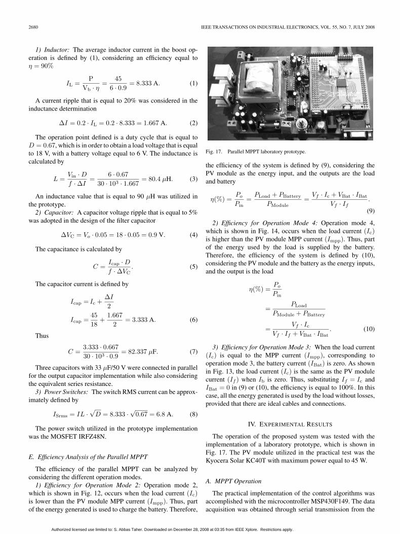
Fig. 17. Parallel MPPT laboratory prototype.
the efficiency of the system is defined by (9), considering thePV module as the energy input, and the outputs are the loadand battery
η(%) =Po
Pin=
PLoad + PBattery
PModule=
Vf · Ic + VBat · IBat
Vf · If.
(9)
2) Efficiency for Operation Mode 4: Operation mode 4,which is shown in Fig. 14, occurs when the load current (Ic)is higher than the PV module MPP current (Impp). Thus, partof the energy used by the load is supplied by the battery.Therefore, the efficiency of the system is defined by (10),considering the PV module and the battery as the energy inputs,and the output is the load
η(%) =Po
Pin
=PLoad
PModule + PBattery
=Vf · Ic
Vf · If + VBat · IBat. (10)
3) Efficiency for Operation Mode 3: When the load current(Ic) is equal to the MPP current (Impp), corresponding tooperation mode 3, the battery current (IBat) is zero. As shownin Fig. 13, the load current (Ic) is the same as the PV modulecurrent (If ) when Ib is zero. Thus, substituting If = Ic andIBat = 0 in (9) or (10), the efficiency is equal to 100%. In thiscase, all the energy generated is used by the load without losses,provided that there are ideal cables and connections.
IV. EXPERIMENTAL RESULTS
The operation of the proposed system was tested with theimplementation of a laboratory prototype, which is shown inFig. 17. The PV module utilized in the practical test was theKyocera Solar KC40T with maximum power equal to 45 W.
A. MPPT Operation
The practical implementation of the control algorithms wasaccomplished with the microcontroller MSP430F149. The dataacquisition was obtained through serial transmission from the
Authorized licensed use limited to: S. Abbas Taher. Downloaded on December 28, 2008 at 03:35 from IEEE Xplore. Restrictions apply.
GULES et al.: MAXIMUM POWER POINT TRACKING SYSTEM FOR PV STAND-ALONE APPLICATIONS 2681
Fig. 18. Output power and current of the PV module.
Fig. 19. Output current and voltage of the PV module.
Fig. 20. Data acquisition of the parallel MPPT operation.
microcontroller to a computer. The main control information,such as voltage, current, power, and converter duty cycle, isstored during MPPT operation.
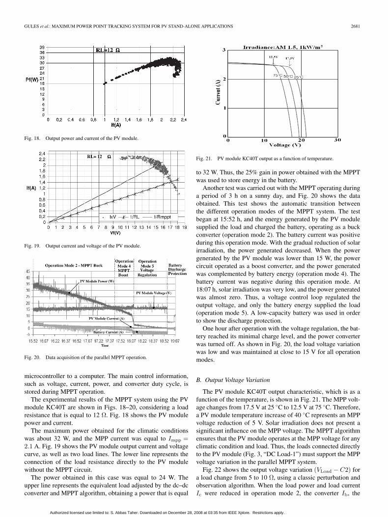
The experimental results of the MPPT system using the PVmodule KC40T are shown in Figs. 18–20, considering a loadresistance that is equal to 12 Ω. Fig. 18 shows the PV modulepower and current.
The maximum power obtained for the climatic conditionswas about 32 W, and the MPP current was equal to Impp =2.1 A. Fig. 19 shows the PV module output current and voltagecurve, as well as two load lines. The lower line represents theconnection of the load resistance directly to the PV modulewithout the MPPT circuit.
The power obtained in this case was equal to 24 W. Theupper line represents the equivalent load adjusted by the dc–dcconverter and MPPT algorithm, obtaining a power that is equal
Fig. 21. PV module KC40T output as a function of temperature.
to 32 W. Thus, the 25% gain in power obtained with the MPPTwas used to store energy in the battery.
Another test was carried out with the MPPT operating duringa period of 3 h on a sunny day, and Fig. 20 shows the dataobtained. This test shows the automatic transition betweenthe different operation modes of the MPPT system. The testbegan at 15:52 h, and the energy generated by the PV modulesupplied the load and charged the battery, operating as a buckconverter (operation mode 2). The battery current was positiveduring this operation mode. With the gradual reduction of solarirradiation, the power generated decreased. When the powergenerated by the PV module was lower than 15 W, the powercircuit operated as a boost converter, and the power generatedwas complemented by battery energy (operation mode 4). Thebattery current was negative during this operation mode. At18:07 h, solar irradiation was very low, and the power generatedwas almost zero. Thus, a voltage control loop regulated theoutput voltage, and only the battery energy supplied the load(operation mode 5). A low-capacity battery was used in orderto show the discharge protection.
One hour after operation with the voltage regulation, the bat-tery reached its minimal charge level, and the power converterwas turned off. As shown in Fig. 20, the load voltage variationwas low and was maintained at close to 15 V for all operationmodes.
B. Output Voltage Variation
The PV module KC40T output characteristic, which is as afunction of the temperature, is shown in Fig. 21. The MPP volt-age changes from 17.5 V at 25 C to 12.5 V at 75 C. Therefore,a PV module temperature increase of 40 C represents an MPPvoltage reduction of 5 V. Solar irradiation does not present asignificant influence on the MPP voltage. The MPPT algorithmensures that the PV module operates at the MPP voltage for anyclimatic condition and load. Thus, the loads connected directlyto the PV module (Fig. 3, “DC Load-1”) must support the MPPvoltage variation in the parallel MPPT system.
Fig. 22 shows the output voltage variation (VLoad − C2) fora load change from 5 to 10 Ω, using a classic perturbation andobservation algorithm. When the load power and load currentIc were reduced in operation mode 2, the converter Ib, the
Authorized licensed use limited to: S. Abbas Taher. Downloaded on December 28, 2008 at 03:35 from IEEE Xplore. Restrictions apply.
2682 IEEE TRANSACTIONS ON INDUSTRIAL ELECTRONICS, VOL. 55, NO. 7, JULY 2008
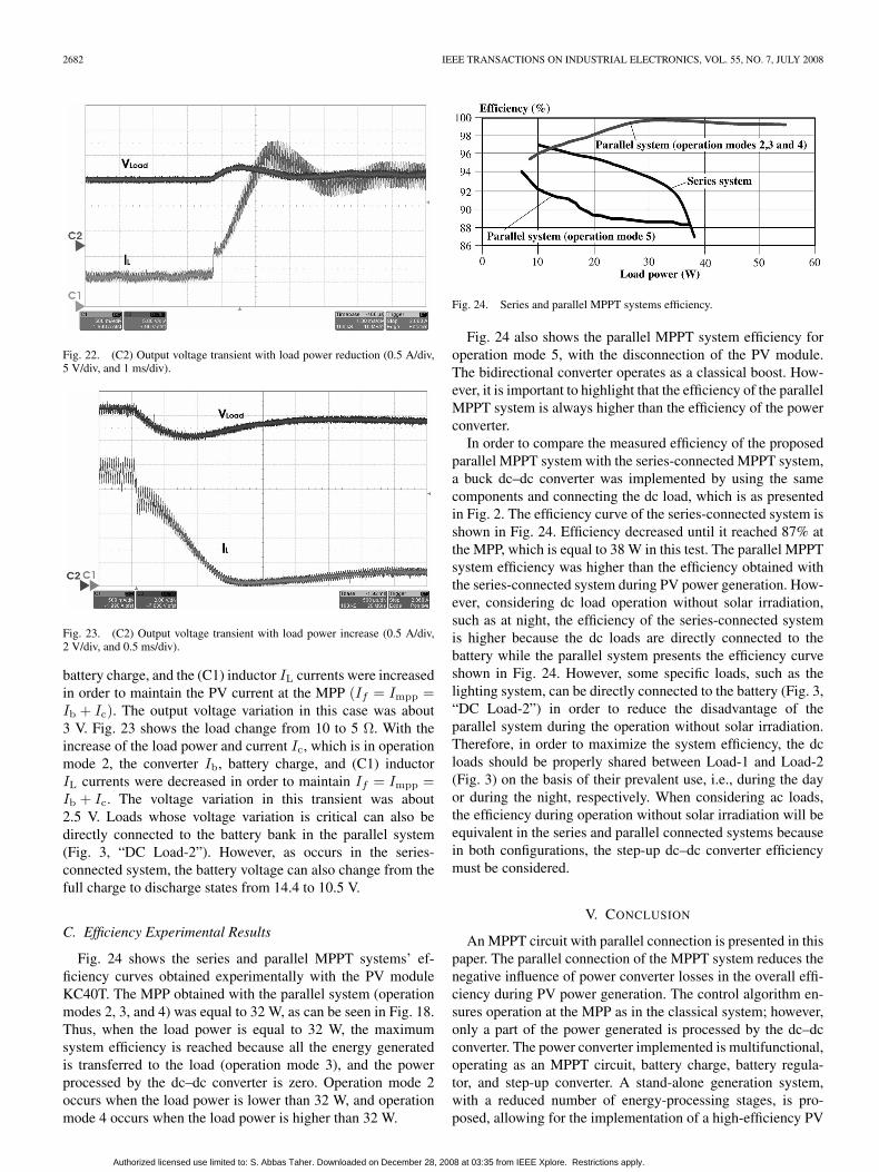
Fig. 22. (C2) Output voltage transient with load power reduction (0.5 A/div,5 V/div, and 1 ms/div).
Fig. 23. (C2) Output voltage transient with load power increase (0.5 A/div,2 V/div, and 0.5 ms/div).
battery charge, and the (C1) inductor IL currents were increasedin order to maintain the PV current at the MPP (If = Impp =Ib + Ic). The output voltage variation in this case was about3 V. Fig. 23 shows the load change from 10 to 5 Ω. With theincrease of the load power and current Ic, which is in operationmode 2, the converter Ib, battery charge, and (C1) inductorIL currents were decreased in order to maintain If = Impp =Ib + Ic. The voltage variation in this transient was about2.5 V. Loads whose voltage variation is critical can also bedirectly connected to the battery bank in the parallel system(Fig. 3, “DC Load-2”). However, as occurs in the series-connected system, the battery voltage can also change from thefull charge to discharge states from 14.4 to 10.5 V.
C. Efficiency Experimental Results
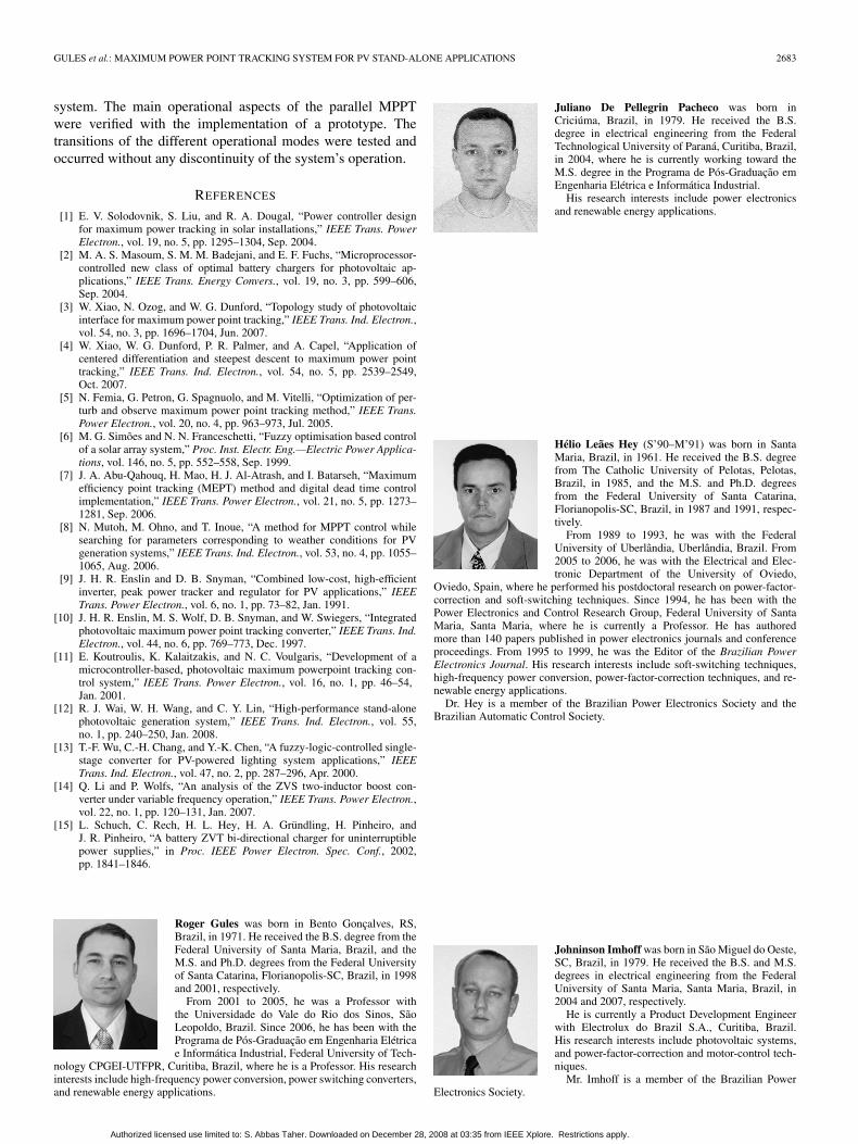
Fig. 24 shows the series and parallel MPPT systems’ ef-ficiency curves obtained experimentally with the PV moduleKC40T. The MPP obtained with the parallel system (operationmodes 2, 3, and 4) was equal to 32 W, as can be seen in Fig. 18.Thus, when the load power is equal to 32 W, the maximumsystem efficiency is reached because all the energy generatedis transferred to the load (operation mode 3), and the powerprocessed by the dc–dc converter is zero. Operation mode 2occurs when the load power is lower than 32 W, and operationmode 4 occurs when the load power is higher than 32 W.
Fig. 24. Series and parallel MPPT systems efficiency.
Fig. 24 also shows the parallel MPPT system efficiency foroperation mode 5, with the disconnection of the PV module.The bidirectional converter operates as a classical boost. How-ever, it is important to highlight that the efficiency of the parallelMPPT system is always higher than the efficiency of the powerconverter.
In order to compare the measured efficiency of the proposedparallel MPPT system with the series-connected MPPT system,a buck dc–dc converter was implemented by using the samecomponents and connecting the dc load, which is as presentedin Fig. 2. The efficiency curve of the series-connected system isshown in Fig. 24. Efficiency decreased until it reached 87% atthe MPP, which is equal to 38 W in this test. The parallel MPPTsystem efficiency was higher than the efficiency obtained withthe series-connected system during PV power generation. How-ever, considering dc load operation without solar irradiation,such as at night, the efficiency of the series-connected systemis higher because the dc loads are directly connected to thebattery while the parallel system presents the efficiency curveshown in Fig. 24. However, some specific loads, such as thelighting system, can be directly connected to the battery (Fig. 3,“DC Load-2”) in order to reduce the disadvantage of theparallel system during the operation without solar irradiation.Therefore, in order to maximize the system efficiency, the dcloads should be properly shared between Load-1 and Load-2(Fig. 3) on the basis of their prevalent use, i.e., during the dayor during the night, respectively. When considering ac loads,the efficiency during operation without solar irradiation will beequivalent in the series and parallel connected systems becausein both configurations, the step-up dc–dc converter efficiencymust be considered.
V. CONCLUSION
An MPPT circuit with parallel connection is presented in thispaper. The parallel connection of the MPPT system reduces thenegative influence of power converter losses in the overall effi-ciency during PV power generation. The control algorithm en-sures operation at the MPP as in the classical system; however,only a part of the power generated is processed by the dc–dcconverter. The power converter implemented is multifunctional,operating as an MPPT circuit, battery charge, battery regula-tor, and step-up converter. A stand-alone generation system,with a reduced number of energy-processing stages, is pro-posed, allowing for the implementation of a high-efficiency PV
Authorized licensed use limited to: S. Abbas Taher. Downloaded on December 28, 2008 at 03:35 from IEEE Xplore. Restrictions apply.
GULES et al.: MAXIMUM POWER POINT TRACKING SYSTEM FOR PV STAND-ALONE APPLICATIONS 2683
system. The main operational aspects of the parallel MPPTwere verified with the implementation of a prototype. Thetransitions of the different operational modes were tested andoccurred without any discontinuity of the system’s operation.
REFERENCES
[1] E. V. Solodovnik, S. Liu, and R. A. Dougal, “Power controller designfor maximum power tracking in solar installations,” IEEE Trans. PowerElectron., vol. 19, no. 5, pp. 1295–1304, Sep. 2004.
[2] M. A. S. Masoum, S. M. M. Badejani, and E. F. Fuchs, “Microprocessor-controlled new class of optimal battery chargers for photovoltaic ap-plications,” IEEE Trans. Energy Convers., vol. 19, no. 3, pp. 599–606,Sep. 2004.
[3] W. Xiao, N. Ozog, and W. G. Dunford, “Topology study of photovoltaicinterface for maximum power point tracking,” IEEE Trans. Ind. Electron.,vol. 54, no. 3, pp. 1696–1704, Jun. 2007.
[4] W. Xiao, W. G. Dunford, P. R. Palmer, and A. Capel, “Application ofcentered differentiation and steepest descent to maximum power pointtracking,” IEEE Trans. Ind. Electron., vol. 54, no. 5, pp. 2539–2549,Oct. 2007.
[5] N. Femia, G. Petron, G. Spagnuolo, and M. Vitelli, “Optimization of per-turb and observe maximum power point tracking method,” IEEE Trans.Power Electron., vol. 20, no. 4, pp. 963–973, Jul. 2005.
[6] M. G. Simões and N. N. Franceschetti, “Fuzzy optimisation based controlof a solar array system,” Proc. Inst. Electr. Eng.—Electric Power Applica-tions, vol. 146, no. 5, pp. 552–558, Sep. 1999.
[7] J. A. Abu-Qahouq, H. Mao, H. J. Al-Atrash, and I. Batarseh, “Maximumefficiency point tracking (MEPT) method and digital dead time controlimplementation,” IEEE Trans. Power Electron., vol. 21, no. 5, pp. 1273–1281, Sep. 2006.
[8] N. Mutoh, M. Ohno, and T. Inoue, “A method for MPPT control whilesearching for parameters corresponding to weather conditions for PVgeneration systems,” IEEE Trans. Ind. Electron., vol. 53, no. 4, pp. 1055–1065, Aug. 2006.
[9] J. H. R. Enslin and D. B. Snyman, “Combined low-cost, high-efficientinverter, peak power tracker and regulator for PV applications,” IEEETrans. Power Electron., vol. 6, no. 1, pp. 73–82, Jan. 1991.
[10] J. H. R. Enslin, M. S. Wolf, D. B. Snyman, and W. Swiegers, “Integratedphotovoltaic maximum power point tracking converter,” IEEE Trans. Ind.Electron., vol. 44, no. 6, pp. 769–773, Dec. 1997.
[11] E. Koutroulis, K. Kalaitzakis, and N. C. Voulgaris, “Development of amicrocontroller-based, photovoltaic maximum powerpoint tracking con-trol system,” IEEE Trans. Power Electron., vol. 16, no. 1, pp. 46–54,Jan. 2001.
[12] R. J. Wai, W. H. Wang, and C. Y. Lin, “High-performance stand-alonephotovoltaic generation system,” IEEE Trans. Ind. Electron., vol. 55,no. 1, pp. 240–250, Jan. 2008.
[13] T.-F. Wu, C.-H. Chang, and Y.-K. Chen, “A fuzzy-logic-controlled single-stage converter for PV-powered lighting system applications,” IEEETrans. Ind. Electron., vol. 47, no. 2, pp. 287–296, Apr. 2000.
[14] Q. Li and P. Wolfs, “An analysis of the ZVS two-inductor boost con-verter under variable frequency operation,” IEEE Trans. Power Electron.,vol. 22, no. 1, pp. 120–131, Jan. 2007.
[15] L. Schuch, C. Rech, H. L. Hey, H. A. Gründling, H. Pinheiro, andJ. R. Pinheiro, “A battery ZVT bi-directional charger for uninterruptiblepower supplies,” in Proc. IEEE Power Electron. Spec. Conf., 2002,pp. 1841–1846.
Roger Gules was born in Bento Gonçalves, RS,Brazil, in 1971. He received the B.S. degree from theFederal University of Santa Maria, Brazil, and theM.S. and Ph.D. degrees from the Federal Universityof Santa Catarina, Florianopolis-SC, Brazil, in 1998and 2001, respectively.
From 2001 to 2005, he was a Professor withthe Universidade do Vale do Rio dos Sinos, SãoLeopoldo, Brazil. Since 2006, he has been with thePrograma de Pós-Graduação em Engenharia Elétricae Informática Industrial, Federal University of Tech-
nology CPGEI-UTFPR, Curitiba, Brazil, where he is a Professor. His researchinterests include high-frequency power conversion, power switching converters,and renewable energy applications.
Juliano De Pellegrin Pacheco was born inCriciúma, Brazil, in 1979. He received the B.S.degree in electrical engineering from the FederalTechnological University of Paraná, Curitiba, Brazil,in 2004, where he is currently working toward theM.S. degree in the Programa de Pós-Graduação emEngenharia Elétrica e Informática Industrial.
His research interests include power electronicsand renewable energy applications.
Hélio Leães Hey (S’90–M’91) was born in SantaMaria, Brazil, in 1961. He received the B.S. degreefrom The Catholic University of Pelotas, Pelotas,Brazil, in 1985, and the M.S. and Ph.D. degreesfrom the Federal University of Santa Catarina,Florianopolis-SC, Brazil, in 1987 and 1991, respec-tively.
From 1989 to 1993, he was with the FederalUniversity of Uberlândia, Uberlândia, Brazil. From2005 to 2006, he was with the Electrical and Elec-tronic Department of the University of Oviedo,
Oviedo, Spain, where he performed his postdoctoral research on power-factor-correction and soft-switching techniques. Since 1994, he has been with thePower Electronics and Control Research Group, Federal University of SantaMaria, Santa Maria, where he is currently a Professor. He has authoredmore than 140 papers published in power electronics journals and conferenceproceedings. From 1995 to 1999, he was the Editor of the Brazilian PowerElectronics Journal. His research interests include soft-switching techniques,high-frequency power conversion, power-factor-correction techniques, and re-newable energy applications.
Dr. Hey is a member of the Brazilian Power Electronics Society and theBrazilian Automatic Control Society.
Johninson Imhoff was born in São Miguel do Oeste,SC, Brazil, in 1979. He received the B.S. and M.S.degrees in electrical engineering from the FederalUniversity of Santa Maria, Santa Maria, Brazil, in2004 and 2007, respectively.
He is currently a Product Development Engineerwith Electrolux do Brazil S.A., Curitiba, Brazil.His research interests include photovoltaic systems,and power-factor-correction and motor-control tech-niques.
Mr. Imhoff is a member of the Brazilian PowerElectronics Society.
Authorized licensed use limited to: S. Abbas Taher. Downloaded on December 28, 2008 at 03:35 from IEEE Xplore. Restrictions apply.