Embed Size (px)
Citation preview
A microstructure-dependent orthotropic plate model based on a modified couple stress theory
G.C. Tsiatas & A.J. Yiotis Institute of Structural Analysis, School of Civil Engineering, National Technical University of Athens, Greece.
Abstract
In this paper, a modified couple stress model containing only one material length scale parameter is developed for the static analysis of orthotropic micro-plates with arbitrary shape. The proposed model is capable of handling plates with complex geometries and boundary conditions. From a variational procedure, the governing equilibrium equation of the micro-plate and most of the general boundary conditions are derived, in terms of the deflection, using the principle of minimum potential energy. The resulting boundary value problem is of the fourth order (instead of existing gradient theories which is of the sixth order) and it is solved using the analogue equation method. Several plates of various shapes, aspect and Poisson’s ratios are analysed to illustrate the applicability of the developed micro-plate model and to reveal the differences between the current model and the classical plate model. Moreover, useful conclusions are drawn from the micron-scale response of this new orthotropic plate model.
Keywords: Couple stress elasticity, Gradient elasticity, Orthotropic plate, Analogue equation method, Meshless methods.
1 Introduction
Since the classical continuum theory is inadequate to predict the behaviour of micron-scaled structures, which has been proven experimentally to be size dependent, the utilisation of strain gradient (higher order) theories is inevitable. Although these general theories encounter the physical problem, they contain
www.witpress.com, ISSN 1755-8336 (on-line) WIT Transactions on State of the Art in Science and Engineering, Vol , © 2010 WIT Press43
doi:10.2495/978-1-84564- - /492 5 22
296 Recent Developments in Boundary Element Methods
additional constants which are difficult to determine even in their simplified form of only two constants. Thus, gradient elasticity theories involving only one additional material constant are very attractive. The couple stress theory is a special case of these higher-order theories in which the effects of the dilatation gradient and the deviatoric stretch gradient are assumed to be negligible. An analytic presentation of the aforementioned theories can be found in [1–3].
The work that has been reported on the subject is restricted only to the vibration and buckling problems of orthotropic nano-plates of graphene sheet. More specifically, Sakhaee-Pour [4] studied the elastic buckling problem of single-layered graphene sheet by an atomistic modelling approach, while Pradhan and Phadikar [5] carried out the vibration analysis of embedded multi-layered graphene sheets and Murmu and Pradhan [6] solved the buckling problem of single-layered graphene sheet employing the nonlocal elasticity theory of Eringen [7].
In this work, the simplified couple stress theory of Yang et al. [8] is developed for the static solution of orthotropic Kirchhoff micro-plates with arbitrary shape. Yang et al., modifying the classical couple stress theory, proposed a couple stress model in which only one material length parameter is needed to capture the size effect. This simplified couple stress theory is based on an additional equilibrium relation, which forces the couple stress tensor to be symmetric. So far, it has been developed for the static bending [9] and free vibration [10] problems of a Bernoulli-Euler beam, for the static bending and free vibration problems of a Timoshenko beam [11] and for the solution of a simple shear problem [12] after the derivation of the boundary conditions and the governing differential equation of the theory in terms of the displacement. Moreover, Tsiatas [13] studied the static bending problem of Kirchhoff plates and Tsiatas and Katsikadelis [14] the Saint-Venant torsion problem of micro-bars.
The proposed model is capable to handle plates with complex geometries and boundary conditions. To the authors’ knowledge, publications on the solution of the particular problem have not been reported in literature. The rest of the paper is organised as follows. In Section 2, the governing equilibrium equation, together with the pertinent boundary conditions in terms of the deflection is derived in its most general form, including elastic support or restraint. The resulting boundary value problem of the micro-plate is of the fourth order and it is solved using the analogue equation method (AEM) in Section 3. Rectangular and elliptical plates of various aspect and Poisson’s ratios are analysed in Section 4 to illustrate the developed orthotropic micro-plate model and to reveal the differences between the current model and the classical plate model. Finally, a summary of conclusions is given in Section 5.
2 Problem formulation
Consider an initially flat thin elastic plate of thickness h consisting of homogeneous orthotropic linearly elastic material occupying the two-dimensional
www.witpress.com, ISSN 1755-8336 (on-line) WIT Transactions on State of the Art in Science and Engineering, Vol , © 2010 WIT Press43
Recent Developments in Boundary Element Methods 297
multiply connected domain Ω of arbitrary shape in the x,y plane bounded by the K+1 curves 0 1 2, , , , KΓ Γ Γ … Γ . The curves ( 0,1, 2, , )i i KΓ = … may be piece-wise smooth, i.e. they may have a finite number of corners. The plate is bending under the combined action of the distributed transverse load ( , )q x y , the edge
moment nnM and the edge force nV producing a three-dimensional deformation state, including the transverse deflection ( , )w x y and the in-plane displacements, which in the absence of in-plane forces are given as [13] ,( , , ) , , ( , , ) .x yu x y z zw v x y z zw= − = − (1a,b)
Subsequently, the displacement and rotation vectors of the micro-plate become [13] , 1 , 2 3 ,x yzw zw w= − − +u e e e (2)
, 1 , 2 ,y xw w= −θ e e (3)
and the nonzero components of the strain and curvature tensor take the form [13] , , ,, , 2 ,x xx y yy xy xyε zw ε zw zwγ= − = − = − (4a,b,c)
, , , ,1, , ( ).2
x xy y xy xy yy xxw w w wχ χ χ= = − = − (5a,b,c)
The components of the bending moment tensor [15] and the couple moment tensor [13] are given as 11 , 12 , 22 , 12 ,, ,x xx yy y yy xxM D w D w M D w D w= − − = − − (6a,b)
66 ,2 ,xy xyM D w= (6c)
, , , ,2 , 2 , ( ),l l lx xy y xy xy yy xxY D w Y D w Y D w w= = − = − (7a,b,c)
respectively, where D11, D12, D22 and D66 are the orthotropic plate rigidities and Dl is the contribution of rotation gradients to the bending rigidity. Using the minimum potential energy principle, the governing equilibrium equation is obtained as [13]
, , ,( ) (2 ) ( ) 0x xy xx xy x y xy y xy yyM Y M Y Y M Y q+ − + − + − + = (8)
in Ω, together with the boundary conditions
* *2 2 , or2
n nt nt n tn nt s n
M M Y Y Y Q M V w wn s n s
∂ ∂ ∂ ∂ −⎛ ⎞− + − = − = =⎜ ⎟⎝ ⎠∂ ∂ ∂ ∂
(9a)
*, ,orn nt nn nn n nM Y M M w w+ = = = (9b)
www.witpress.com, ISSN 1755-8336 (on-line) WIT Transactions on State of the Art in Science and Engineering, Vol , © 2010 WIT Press43
298 Recent Developments in Boundary Element Methods
on Γ and
* 0 or2
n tnt nt k kkkk k
Y YM M w w−⎡ ⎤ ⎡ ⎤+ = = =⎣ ⎦⎢ ⎥⎣ ⎦∑ ∑ (10)
at the k-th corner, where
* ( ) cos2
( ) sin ,2
x yn x xy xy
x yy xy xy
Y YQ M Y M ax y
Y YM Y M ay x
−⎡ ⎤∂ ∂ ⎛ ⎞= + − +⎜ ⎟⎢ ⎥⎝ ⎠∂ ∂⎣ ⎦
−⎡ ⎤∂ ∂ ⎛ ⎞+ − − +⎜ ⎟⎢ ⎥⎝ ⎠∂ ∂⎣ ⎦
(11)
* 2 2( )cos ( )sin
2 cos sin ,2
nn x xy y xy
x yxy
M M Y a M Y a
Y YM a a
= + + −
−⎛ ⎞− +⎜ ⎟⎝ ⎠
(12)
* 2 2(cos sin )
2( 2 )cos sin
x ynt xy
x y xy
Y YM M a a
M M Y a a
−⎛ ⎞= + −⎜ ⎟⎝ ⎠
+ − +
(13)
are the stress resultants and ,a x= n . In eqns (8–10) n,t denote the directions normal and tangent to the plate boundary and s its arc length (intrinsic coordinates [16]). Using eqns (6) and (7) the above relations become
*1 , 2 , 3 , 4 , ,n xxx xxy xyy yyyQ f w f w f w f w= + + + (14)
*1 , 2 , 3 , ,nn xx xy yyM g w g w g w= + + (15)
*1 , 2 , 3 , ,nt xx xy yyM h w h w h w= + + (16)
where
1 11 2 12 66( )cos , ( )sin 2( )sin ,l l lf D D a f D D a D D a= − + = − − − + (17a,b)
3 12 66 4 22( )cos 2( )cos , ( )sin ,l l lf D D a D D a f D D a= − − − + = − + (17c,d)
2 21 11 12( )cos ( )sin ,l lg D D a D D a= − + − − (18a)
2 664( )cos sin ,lg D D a a= − + (18b)
2 23 12 22( )cos ( )sin ,l lg D D a D D a= − − − + (18c)
www.witpress.com, ISSN 1755-8336 (on-line) WIT Transactions on State of the Art in Science and Engineering, Vol , © 2010 WIT Press43
Recent Developments in Boundary Element Methods 299
1 11 12( 2 )cos sin ,lh D D D a a= − + − (19a)
2 22 662( )(cos sin ),lh D D a a= + − (19b)
3 12 22( 2 )cos sin .lh D D D a a= − + + (19c)
Substituting eqns (6) and (7) into eqn (8) yields the governing equation of the micro-plate in terms of the deflection
11 , 12 66 , 22 ,( ) 2( 2 ) ( )l l lxxxx xxyy yyyyD D w D D D w D D w q+ + + + + + = (20)
in Ω. The boundary conditions (9a,b) can be rewritten in the most general form, including elastic support or restraint, as
* *1 2 3 1 2 3, , ,n n nnw V w Mβ β β γ γ γ+ = + = (21a,b)
where βi, γi are functions specified on Γ and
*1 , 2 , 3 , 4 ,n xxx xxy xyy yyyV f w f w f w f w= + + + (22)
is the effective shear force, with
2 21 11 12( )cos (1 sin ) ( )cos sin ,l lf D D a a D D a a= − + + + − (23a)
2
2 12
3 266 11
( )sin (1 cos )
4( )sin ( )cos sin ,
l
l l
f D D a a
D D a D D a a
= − − +
− + + + (23b)
2
3 12
3 266 22
( )cos (1 sin )
4( )cos ( )sin cos ,
l
l l
f D D a a
D D a D D a a
= − − +
− + + + (23c)
2 24 22 12( )sin (1 cos ) ( )sin cos .l lf D D a a D D a a= − + + + − (23d)
Note that all conventional boundary conditions can be derived from eqns (21) by specifying appropriately the βi and γi functions. When the boundary Γ is non-smooth, the following corner condition must be added to eqns (21)
*1 2 3 2, 0,k k k nt k kk
a w a M a a⎡ ⎤+ = ≠⎣ ⎦ (24)
in which aik are constants specified at the k-th corner. One can observe that for 0ll D= = eqns (20), (21) and (24) yield the governing equation and the general
boundary conditions of the orthotropic Kirchhoff plate theory [15].
www.witpress.com, ISSN 1755-8336 (on-line) WIT Transactions on State of the Art in Science and Engineering, Vol , © 2010 WIT Press43
300 Recent Developments in Boundary Element Methods
Finally, the transformed (including the influence of the rotation gradients) stress resultants at a point inside Ω are given as
*11 , 12 ,( ) ( ) ,l l
x xx yyM D D w D D w= − + − − (25a)
* *12 , 22 , 66 ,( ) ( ) , 2( ) ,l l l
y xx yy xy xyM D D w D D w M D D w= − − − + = + (25b,c)
*11 , 12 66 ,( ) ( 2 ) ,l l
x xxx xyyQ D D w D D D w= − + − + + (25d)
*22 , 12 66 ,( ) ( 2 ) .l l
y yyy xxyQ D D w D D D w= − + − + + (25e)
The above stress resultants consist of two components. The first component is due to plate bending and the second one is due to the microstructure plate bending effect.
3 The AEM solution
The boundary value problem described by eqns (20) and (21) is solved using the AEM. Let w be the sought solution of eqn (20). This function is four times continuously differentiable with respect to the spatial co-ordinates x, y in Ω and three times differentiable on its boundary Γ. According to the concept of the analogue equation of Katsikadelis, as it was developed for the complete fourth-order plate equation [17], eqn (20) can be replaced by the biharmonic equation
4 ( , ),w b x y∇ = (26)
where ( , )b x y is the unknown fictitious source, which is approximated as [18]
1
,M
j jj
b fα=
= ∑ (27)
where ( , )jf f x y= is a set of approximation functions and aj are M unknown
coefficients. We look for solution of the form pw w+ , where w is the homogeneous and pw a particular solution. The particular solution is obtained as
1
ˆM
pj j
jw wα
== ∑ (28)
where ˆ jw is a particular solution of the equation
4 ˆ j jw f∇ = (29)
The particular solution to eqn (29) can always be determined, if fj is specified.
www.witpress.com, ISSN 1755-8336 (on-line) WIT Transactions on State of the Art in Science and Engineering, Vol , © 2010 WIT Press43
Recent Developments in Boundary Element Methods 301
The homogeneous solution is obtained from the boundary value problem
4 0 in ,w∇ = Ω (30)
* *1 2 3 1 2
1 1ˆ ˆ( ) ( ) ( ) ,
M M
n j j j n jj j
w V w w V wβ β β β α β α= =
⎡ ⎤+ = − +⎢ ⎥
⎣ ⎦∑ ∑ (31a)
* *1 2 3 1 2
1 1ˆ ˆ, ( ) ( ), ( ) ,
M M
n nn j j n j nn jj j
w M w w M wγ γ γ γ α γ α= =
⎡ ⎤+ = − +⎢ ⎥
⎣ ⎦∑ ∑ (31b)
on Γ. Thus, the solution of eqn (26), for points x∈Ω , is written in integral form as
* * * *, ,
1
( ) ( ) ( ) ( ) ( ) d
ˆ ( ).
n n n nn n nn
M
j jj
w wV v vV w v M w w M v s
a w
Γ
=
⎡ ⎤= − − + −⎣ ⎦
+
∫
∑
x
x (32)
For points ∈Γx where the boundary is smooth, the two boundary integral equations for the deflection and its normal derivative are given as [18]
* * * *, ,
1
1 ( ) ( ) ( ) ( ) ( ) d2
ˆ ( ),
n n n nn n nn
M
j jj
w wV v vV w v M w w M v s
a w
Γ
=
⎡ ⎤= − − + −⎣ ⎦
+
∫
∑
x
x (33)
* * * *, , , , , ,
,1
1 ( ) ( ) ( ) ( ) ( ) d2
ˆ ( ) .
n n n nn n nn
M
j jj
w wV v v V w v M w w M v s
a w
ν ν ν ν ν
ν
Γ
=
⎡ ⎤= − − + −⎣ ⎦
+
∫
∑
x
x (34)
The subscript v in eqn (34) indicates that the normal derivative is taken with respect to point x ∈Γ . Moreover, the kernels v, v,n, * ( )nnM v , * ( )nV v and ,vν ,
, nvν , *,( )nnM vν , *
,( )nV vν in the above relations can be readily found using the Rayleigh–Green identity with the help of eqns (9–13) as in [19].
The first and second derivatives of the displacements for points inside Ω are obtained by direct differentiation of eqn (32). Thus, for the sake of conciseness, we can write the integral representations of the deflections and its derivatives up to the third order
* *
, ,, ,
* * 1,
( ) ( )ˆ( ) d ( ) ,
( ) , ( , )
Mn pqr pqr npqr j j pqr
jnpqr nn n nn pqr
wV v v V ww s a w
v M w w M vΓ =
⎡ ⎤− += − +⎢ ⎥
⎢ ⎥−⎣ ⎦∑∫x x (35)
where , , 0, ,p q r x y= .
www.witpress.com, ISSN 1755-8336 (on-line) WIT Transactions on State of the Art in Science and Engineering, Vol , © 2010 WIT Press43
302 Recent Developments in Boundary Element Methods
The final step of AEM is to apply eqn (20) to the M points inside Ω and replace the involved values of the deflection and its derivatives using eqns (32) and (35) after the elimination of the boundary quantities w , *
nV ,nw and *nnM
with the help of the boundary conditions (31). Thus, we obtain the following set of M linear algebraic equations [18]
,α =F g (36)
where F is a known M M× matrix, g is also a known 1M × vector and α is the vector of the M coefficients to be determined. Once α is determined, the solution to the problem function w and its derivatives are evaluated from eqns (32) and (35).
4 Numerical examples
On the basis of the numerical procedure presented in the previous section, a FORTRAN code has been written and numerical results for certain micro-plates have been obtained, which illustrate the applicability, effectiveness and accuracy of the proposed model. The employed approximation functions are the multiquadrics, which are defined as
2 2 ,jf r c= + (37)
where c is an arbitrary constant. Using these radial base functions, a particular solution of eqn (29) is obtained as
( ) ( )2 2 2 3 2 2 5 2 2 2
5 3 2 4 2 2 2 2 5/2 2 2 2 3/2
1 7ˆ ln ( ) ln12 60
1 1 7 1 2( ) ( ) .12 12 60 225 45
jw c r c c c r c c c r c c
c c r c r c r c c r c
= − + + + + + +
− + − + + + + + (38)
4.1 Rectangular micro-plate
A rectangular simply supported micro-plate with various aspect ratios, subjected to a uniform load, has been analysed (N=80, M=225). First, a square orthotropic plate ( 0ll D= = ) was investigated in order to compare the results with those obtained by previous investigators [15,20–22]. The rigidities are given as
2 3 3 31 1 2 12
11 22 12 22 662 21 2 1 2
, , , ,12( ) 12( ) 12
E h E E h G hD D D D DE E E E
νν ν
= = = =− −
where the employed data are: E1 = 206800, 2 1 / 15E E= , v=0.30, G12 = 605.5 and 10a b= = , 0.01h = , 1q = . In Table 1, results for the deflection and
www.witpress.com, ISSN 1755-8336 (on-line) WIT Transactions on State of the Art in Science and Engineering, Vol , © 2010 WIT Press43
Recent Developments in Boundary Element Methods 303
bending moments at the centre of the plate are presented, which are in very good agreement compared with those obtained from the analytic solution of Lekhnitskii [22].
Afterwards, the response of the same plate was investigated taking into account the microstructural effect, as measured by the material length scale parameter l ( 2
12lD l G h= ). In order to examine the influence of the micro-plate shape on the
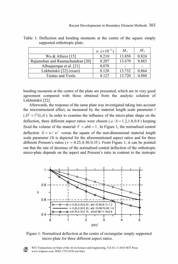
deflection, three different aspect ratios were chosen ( / 1.2,1.0,0.8a b = ) keeping fixed the volume of the material 1V abh= = . In Figure 1, the normalised central deflection / cw w w= versus the square of the non-dimensional material length scale parameter l/h is depicted for the aforementioned aspect ratios and for three different Poisson’s ratios ( 0.25,0.30,0.35ν = ). From Figure 1, it can be pointed out that the rate of decrease of the normalised central deflection of the orthotropic micro-plate depends on the aspect and Poisson’s ratio in contrast to the isotropic
Table 1: Deflection and bending moments at the centre of the square simply supported orthotropic plate.
w ( 310−× ) xM yM Wu & Altiero [15] 8.210 13.858 0.824
Rajamohan and Raamachandran [20] 8.207 13.670 0.883 Albuquerque et al. [21] 8.078 - - Lekhnitskii [22] (exact) 8.120 13.732 0.864
Tsiatas and Yiotis 8.127 13.720 0.888
Figure 1: Normalised deflection at the centre of rectangular simply supportedmicro-plate for three different aspect ratios.
www.witpress.com, ISSN 1755-8336 (on-line) WIT Transactions on State of the Art in Science and Engineering, Vol , © 2010 WIT Press43
304 Recent Developments in Boundary Element Methods
one which depends only on the Poisson’s ratio [13]. Moreover, for a given aspect ratio, the rate of decrease of the normalised central deflection is totally independent of the Poisson’s ratio. From the presented results, it can be also concluded that the deflection is decreased, in general, nonlinearly with the increase of l/h. However, for the examined orthotropic material, the nonlinearity increases with the decrease of the aspect ratio. From the same figure, it is also observed that the deflection of the micro-plates decreases with the increase of the aspect ratio.
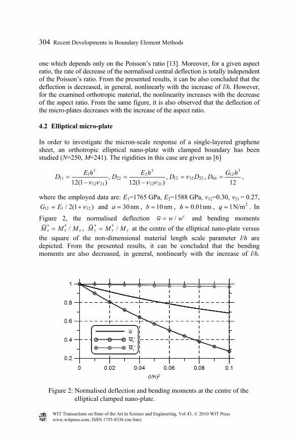
4.2 Elliptical micro-plate
In order to investigate the micron-scale response of a single-layered graphene sheet, an orthotropic elliptical nano-plate with clamped boundary has been studied (N=250, M=241). The rigidities in this case are given as [6]
3 3 3
1 2 1211 22 12 12 22 66
12 21 12 21, , , ,
12(1 ) 12(1 ) 12E h E h G hD D D D Dνν ν ν ν
= = = =− −
where the employed data are: E1=1765 GPa, E2=1588 GPa, v12=0.30, v21 = 0.27, 12 1 12/ 2(1 )G E ν= + and 30nma = , 10nmb = , 0.01nmh = , 21N/mq = . In
Figure 2, the normalised deflection / cw w w= and bending moments * * /x x xM M M= , * * /y y yM M M= at the centre of the elliptical nano-plate versus
the square of the non-dimensional material length scale parameter l/h are depicted. From the presented results, it can be concluded that the bending moments are also decreased, in general, nonlinearly with the increase of l/h.
Figure 2: Normalised deflection and bending moments at the centre of theelliptical clamped nano-plate.
www.witpress.com, ISSN 1755-8336 (on-line) WIT Transactions on State of the Art in Science and Engineering, Vol , © 2010 WIT Press43
Recent Developments in Boundary Element Methods 305
However, the rate of decrease of the normalised quantity *xM is greater
compared with that of w and *yM .
5 Conclusions
In this paper, a new plate model was developed for the static analysis of orthotropic micro-plates with arbitrary shape containing only one internal material length scale parameter which can capture the size effect. The governing equilibrium equation and the most general boundary conditions of the micro-plate are derived in terms of the deflection, using the principle of minimum potential energy. The resulting boundary value problem is of the fourth order and it is solved using the AEM. The main conclusions that can be drawn from this investigation are summarised as:
The present model is alleviated from the drawback of existing micro-plate models, the analytic solutions of which are restricted only to micro-plates with simple geometric shapes.
The rate of decrease of the deflection of a simply supported orthotropic micro-plate depends on the aspect and Poisson’s ratio, in contrast to the isotropic one which depends only on the Poisson’s ratio. Moreover, for a given aspect ratio, the rate of decrease of the deflection is totally independent of the Poisson’s ratio.
For the same examined orthotropic rectangular micro-plate with fixed material volume, it is proved that the smaller the aspect ratio the smaller the deflection.
In the orthotropic elliptical nano-plate with clamped boundary, the deflection as well as the bending moments is also decreased, in general, nonlinearly with the increase of l/h. However, the rate of decrease is different for the normalised deflection and bending moments.
References
[1] Vardoulakis, I. & Sulem, J., Bifurcation Analysis in Geomechanics, Blackie/Chapman and Hall: London, 1995.
[2] Exadaktylos, G.E. & Vardoulakis, I., Microstructure in linear elasticity and scale effects: a reconsideration of basic rock mechanics and rock fracture mechanics. Tectonophysics, 335, pp. 81–109, 2001.
[3] Tsepoura, K., Papargyri-Beskou, S., Polyzos, D. & Beskos, D.E., Static and dynamic analysis of gradient elastic bars in tension. Archive of Applied Mechanics, 72, pp. 483–497, 2002.
[4] Sakhaee-Pour, A., Elastic buckling of single-layered graphene sheet. Computational Materials Science, 45, pp. 266–270, 2009.
[5] Pradhan, S.C. & Phadikar, J.K., Small scale effect on vibration of embedded multilayered graphene sheets based on nonlocal continuum models. Physics Letters A, 373, pp. 1062–1069, 2009.
www.witpress.com, ISSN 1755-8336 (on-line) WIT Transactions on State of the Art in Science and Engineering, Vol , © 2010 WIT Press43
306 Recent Developments in Boundary Element Methods
[6] Murmu, T. & Pradhan, S.C., Buckling of biaxially compressed orthotropic plates at small scales. Mechanics Research Communications, 36, pp. 933–938, 2009.
[7] Eringen, A.C., On differential equations of nonlocal elasticity and solutions of screw dislocation and surface waves. Journal of Applied Physics, 54, pp. 4703–4710, 1983.
[8] Yang, F., Chong, A.C.M., Lam, D.C.C. & Tong, P., Couple stress based strain gradient theory of elasticity. International Journal of Solids and Structures, 39, pp. 2731–2743, 2002.
[9] Park, S.K. & Gao, X.-L., Bernoulli–Euler beam model based on a modified couple stress theory. Journal of Micromechanics and Microengineering, 16, pp. 2355–2359, 2006.
[10] Kong, S., Zhou, S., Nie, Z. & Wang, K., The size-dependent natural frequency of Bernoulli-Euler micro-beams. International Journal of Engineering Science, 46, pp. 427–437, 2008.
[11] Ma, H.M., Gao, X.-L. & Reddy, J.N., A microstructure-dependent Timoshenko beam model based on a modified couple stress theory. Journal of the Mechanics and Physics of Solids, 56, pp. 3379–3391, 2008.
[12] Park, S.K. & Gao, X.-L., Variational formulation of a modified couple stress theory and its application to a simple shear problem. Zeitschrift für Angewandte Mathematik und Physik, 59, pp. 904–917, 2008.
[13] Tsiatas, G.C., A new Kirchhoff plate model based on a modified couple stress theory. International Journal of Solids and Structures, 46, pp. 2757–2764, 2009.
[14] Tsiatas, G.C. & Katsikadelis, J.T., A BEM solution to the Saint-Venant torsion problem of micro-bars. Advances in Boundary Element Techniques X, eds. E.J. Sapountzakis & M.H. Aliabadi, EC Ltd Publications: Eastleigh, UK, pp. 217–224, 2009.
[15] Wu, B.C. & Altiero N.J., A new numerical method for the analysis of anisotropic thin-plate bending problems. Computer Methods in Applied Mechanics and Engineering, 25, pp. 343–353, 1981.
[16] Katsikadelis, J.T., The analysis of plates on elastic foundation by the boundary integral equation method, Ph.D. Thesis, Polytechnic Institute of New York, New York, 1982.
[17] Katsikadelis, J.T. & Yiotis, A.J., The BEM for plates of variable thickness on nonlinear biparametric elastic foundation. An analog equation solution, Journal of Engineering Mathematics, 46, pp. 313–330, 2003.
[18] Chinnaboon, B., Katsikadelis, J.T. & Chucheepsakul, S., A BEM-based meshless method for plates on biparametric elastic foundation with internal supports. Computer Methods in Applied Mechanics and Engineering, 196, pp. 3165–3177, 2007.
[19] Hartmann, F. & Zotemantel, R., The direct boundary element method in plate bending. International Journal for Numerical Methods in Engineering, 23, pp. 2049–2069, 1986.
www.witpress.com, ISSN 1755-8336 (on-line) WIT Transactions on State of the Art in Science and Engineering, Vol , © 2010 WIT Press43
Recent Developments in Boundary Element Methods 307
[20] Rajamohan, C. & Raamachandran, J., Bending of anisotropic plates by charge simulation method. Advances in Engineering Software, 30, pp. 369–373, 1999.
[21] Albuquerque, E.L., Sollero, P., Venturini, W.S. & Aliabadi, M.H., Boundary element analysis of anisotropic Kirchhoff plates. International Journal of Solids and Structures, 43, pp. 4029–4046, 2006.
[22] Lekhnitskii, S.G., Anisotropic plates, Gordon and Breach: New York, 1968.
www.witpress.com, ISSN 1755-8336 (on-line) WIT Transactions on State of the Art in Science and Engineering, Vol , © 2010 WIT Press43