Embed Size (px)
Citation preview
A MULTISCALE DAMAGE MODEL FOR THE ANALYSIS OF LAMINATED COMPOSITE STRUCTURES ON THE
MICROSCALE
P. Ladevèze1,2, M. Trovalet1, G. Lubineau1
1LMT-Cachan (ENS Cachan/CNRS/UPMC/Pres Universud Paris) 61 avenue du Président Wilson, F-94235 Cachan, France
2EADS Foundation Chair “Advanced Computational Structural Mechanics” [email protected]
SUMMARY This paper discusses the capabilities and limits of a multiscale damage model for CFRPs which is capable of describing the damage mechanisms on the microscale. For today’s aerospace applications, this model should be viewed as a virtual reference material.
Keywords: composite, damage, multiscale, micromechanics, laminate
INTRODUCTION Today, laminated composites are increasingly involved in high-performance
applications, particularly in vital parts for the aeronautical industry. This popularity has led to many research works on different scales, resulting in a better understanding and modeling of the damage mechanisms. Still, predicting the evolution of damage (microcracks and delamination) up to final fracture remains a crucial research topic in the mechanics of composite materials and structures.
In this context, a semi-discrete and multiscale approach called the computational damage micromodel for laminated composites was proposed in [1,2]. This approach uses both the micromechanics [3,4,5,6] and mesomechanics [7,8] of laminated composites, and creates a synergy between them. Transverse microcracking and microdelamination are described through discrete cracks, for which minimum cracking surfaces are introduced according to finite fracture mechanics [9]. The cracked ply is assumed to be made of a “fiber-matrix material”, whose homogenized behavior is described through a continuum mechanics model thanks to the “Damage Mesomodel of Laminated Composites” [7,8].
This paper first reviews the basics features of the multiscale damage model, focusing particularly on the material’s parameters. Micro and macro experimental information is used along with the micro-meso bridge introduced in [10,11]. This model should be used as a virtual material i.e. a material database. Several tension tests of samples with or without hole were simulated and compared with experimental data. Finally the current capabilities and limits of this approach are pointed out and its perspectives presented.
PHENOMENOLOGY ON THE MICROSCALE
Numerous theoretical and experimental works on the micromechanics of laminates have already been published (see the two review papers [12],[5], our reference [1], and [4]).
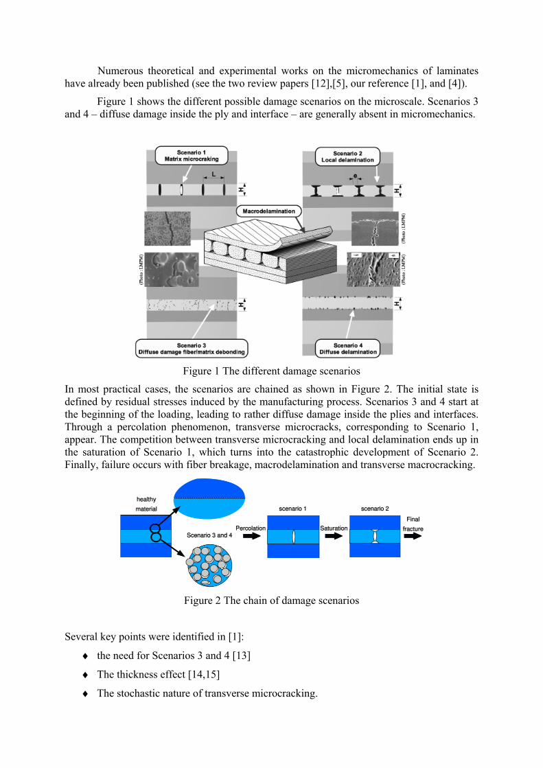
Figure 1 shows the different possible damage scenarios on the microscale. Scenarios 3 and 4 – diffuse damage inside the ply and interface – are generally absent in micromechanics.
Figure 1 The different damage scenarios
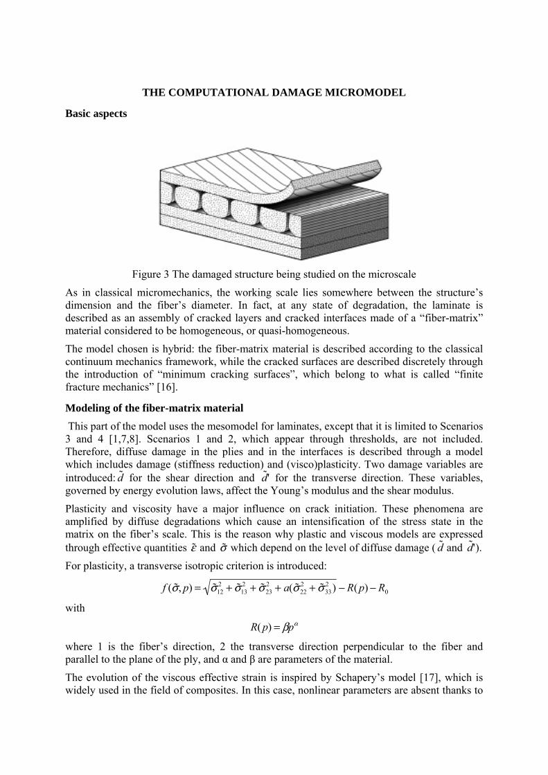
In most practical cases, the scenarios are chained as shown in Figure 2. The initial state is defined by residual stresses induced by the manufacturing process. Scenarios 3 and 4 start at the beginning of the loading, leading to rather diffuse damage inside the plies and interfaces. Through a percolation phenomenon, transverse microcracks, corresponding to Scenario 1, appear. The competition between transverse microcracking and local delamination ends up in the saturation of Scenario 1, which turns into the catastrophic development of Scenario 2. Finally, failure occurs with fiber breakage, macrodelamination and transverse macrocracking.
Figure 2 The chain of damage scenarios
Several key points were identified in [1]:
♦ the need for Scenarios 3 and 4 [13]
♦ The thickness effect [14,15]
♦ The stochastic nature of transverse microcracking.
THE COMPUTATIONAL DAMAGE MICROMODEL
Basic aspects
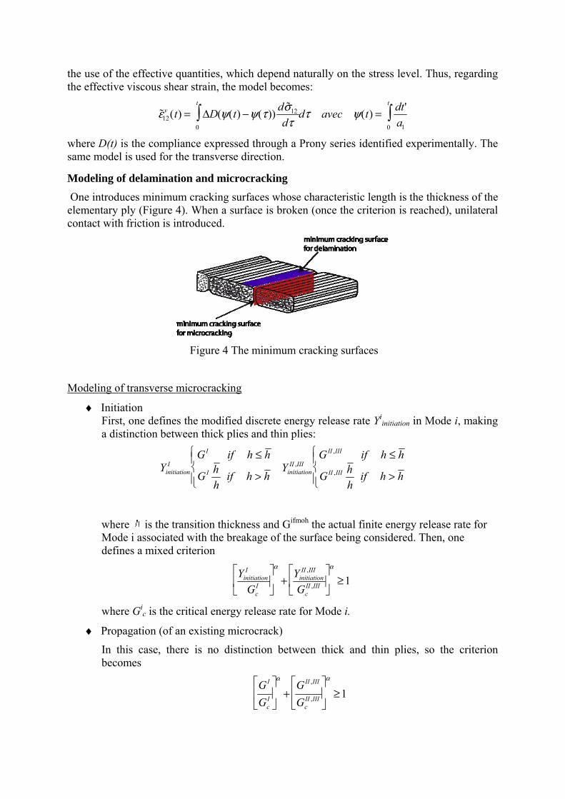
Figure 3 The damaged structure being studied on the microscale
As in classical micromechanics, the working scale lies somewhere between the structure’s dimension and the fiber’s diameter. In fact, at any state of degradation, the laminate is described as an assembly of cracked layers and cracked interfaces made of a “fiber-matrix” material considered to be homogeneous, or quasi-homogeneous.
The model chosen is hybrid: the fiber-matrix material is described according to the classical continuum mechanics framework, while the cracked surfaces are described discretely through the introduction of “minimum cracking surfaces”, which belong to what is called “finite fracture mechanics” [16].
Modeling of the fiber-matrix material This part of the model uses the mesomodel for laminates, except that it is limited to Scenarios 3 and 4 [1,7,8]. Scenarios 1 and 2, which appear through thresholds, are not included. Therefore, diffuse damage in the plies and in the interfaces is described through a model which includes damage (stiffness reduction) and (visco)plasticity. Two damage variables are introduced: ˜ d for the shear direction and ˜ d ' for the transverse direction. These variables, governed by energy evolution laws, affect the Young’s modulus and the shear modulus.
Plasticity and viscosity have a major influence on crack initiation. These phenomena are amplified by diffuse degradations which cause an intensification of the stress state in the matrix on the fiber’s scale. This is the reason why plastic and viscous models are expressed through effective quantities ˜ ε and ˜ σ which depend on the level of diffuse damage ( ˜ d and ˜ d '). For plasticity, a transverse isotropic criterion is introduced:
f ( ˜ σ , p) = ˜ σ 122 + ˜ σ 13
2 + ˜ σ 232 + a( ˜ σ 22
2 + ˜ σ 332 ) − R(p) − R0
with
R( p) = βpα
where 1 is the fiber’s direction, 2 the transverse direction perpendicular to the fiber and parallel to the plane of the ply, and α and β are parameters of the material.
The evolution of the viscous effective strain is inspired by Schapery’s model [17], which is widely used in the field of composites. In this case, nonlinear parameters are absent thanks to
the use of the effective quantities, which depend naturally on the stress level. Thus, regarding the effective viscous shear strain, the model becomes:
˜ ε 12v (t) = ΔD(ψ(t) −ψ(τ )) d ˜ σ 12
dτ0
t
∫ dτ avec ψ(t) = dt'a10
t
∫
where D(t) is the compliance expressed through a Prony series identified experimentally. The same model is used for the transverse direction.
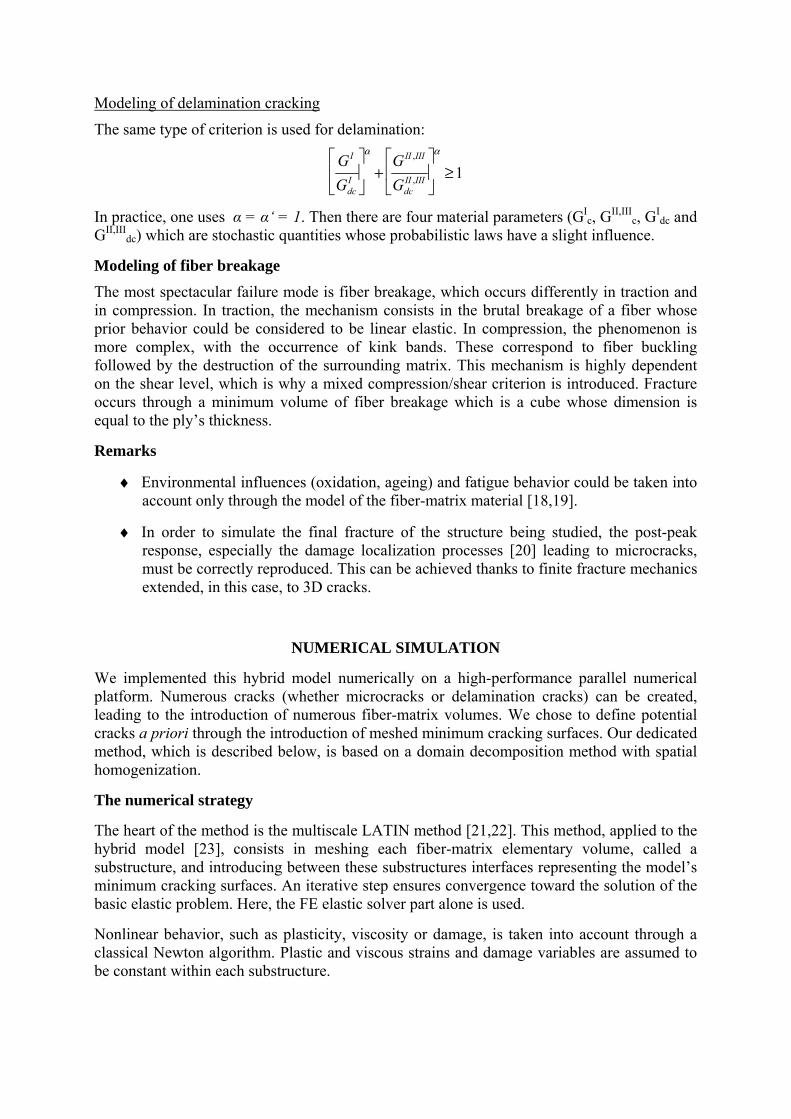
Modeling of delamination and microcracking One introduces minimum cracking surfaces whose characteristic length is the thickness of the elementary ply (Figure 4). When a surface is broken (once the criterion is reached), unilateral contact with friction is introduced.
Figure 4 The minimum cracking surfaces
Modeling of transverse microcracking
♦ Initiation First, one defines the modified discrete energy release rate Yi
initiation in Mode i, making a distinction between thick plies and thin plies:
YinitiationI
GI if h ≤ h
GI h h
if h > h
⎧ ⎨ ⎪
⎩ ⎪ Yinitiation
II ,IIIGII ,III if h ≤ h
GII ,III h h
if h > h
⎧ ⎨ ⎪
⎩ ⎪
where is the transition thickness and Gifmoh the actual finite energy release rate for Mode i associated with the breakage of the surface being considered. Then, one defines a mixed criterion
YinitiationI
GcI
⎡
⎣ ⎢
⎤
⎦ ⎥
α
+ YinitiationII ,III
GcII ,III
⎡
⎣ ⎢
⎤
⎦ ⎥
α
≥1
where Gic is the critical energy release rate for Mode i.
♦ Propagation (of an existing microcrack)
In this case, there is no distinction between thick and thin plies, so the criterion becomes
GI
GcI
⎡
⎣ ⎢
⎤
⎦ ⎥
α
+GII ,III
GcII ,III
⎡
⎣ ⎢
⎤
⎦ ⎥
α
≥1
Modeling of delamination cracking
The same type of criterion is used for delamination:
GI
GdcI
⎡
⎣ ⎢
⎤
⎦ ⎥
α
+GII ,III
GdcII ,III
⎡
⎣ ⎢
⎤
⎦ ⎥
α
≥1
In practice, one uses α = α‘ = 1. Then there are four material parameters (GIc, GII,III
c, GIdc and
GII,IIIdc) which are stochastic quantities whose probabilistic laws have a slight influence.
Modeling of fiber breakage The most spectacular failure mode is fiber breakage, which occurs differently in traction and in compression. In traction, the mechanism consists in the brutal breakage of a fiber whose prior behavior could be considered to be linear elastic. In compression, the phenomenon is more complex, with the occurrence of kink bands. These correspond to fiber buckling followed by the destruction of the surrounding matrix. This mechanism is highly dependent on the shear level, which is why a mixed compression/shear criterion is introduced. Fracture occurs through a minimum volume of fiber breakage which is a cube whose dimension is equal to the ply’s thickness.
Remarks
♦ Environmental influences (oxidation, ageing) and fatigue behavior could be taken into account only through the model of the fiber-matrix material [18,19].
♦ In order to simulate the final fracture of the structure being studied, the post-peak response, especially the damage localization processes [20] leading to microcracks, must be correctly reproduced. This can be achieved thanks to finite fracture mechanics extended, in this case, to 3D cracks.
NUMERICAL SIMULATION
We implemented this hybrid model numerically on a high-performance parallel numerical platform. Numerous cracks (whether microcracks or delamination cracks) can be created, leading to the introduction of numerous fiber-matrix volumes. We chose to define potential cracks a priori through the introduction of meshed minimum cracking surfaces. Our dedicated method, which is described below, is based on a domain decomposition method with spatial homogenization.
The numerical strategy
The heart of the method is the multiscale LATIN method [21,22]. This method, applied to the hybrid model [23], consists in meshing each fiber-matrix elementary volume, called a substructure, and introducing between these substructures interfaces representing the model’s minimum cracking surfaces. An iterative step ensures convergence toward the solution of the basic elastic problem. Here, the FE elastic solver part alone is used.
Nonlinear behavior, such as plasticity, viscosity or damage, is taken into account through a classical Newton algorithm. Plastic and viscous strains and damage variables are assumed to be constant within each substructure.
In order to determine the initiation or propagation of cracking, a calculation of the energy release rate is performed for each potential crack. For each time step, we first solve the global nonlinear problem (plasticity, viscosity, damage) under the assumption that there is no crack initiation or propagation. Then, we search for cracks. For each minimum cracking surface, a calculation of the potential energy of the cracked state enables us to find the discrete energy release rate associated with the breakage of this surface. If the mixed criterion defined previously is reached, the surface is definitively broken. If many cracks reach the criterion simultaneously, the most highly loaded crack is considered to be broken and the others remain healthy. Then, the new global nonlinear problem (with one additional broken surface) is solved with the same loading, and the energy release rate calculations are performed again on each potential crack. Finally, when no crack is propagating anymore, we proceed to the next time step.
By now, it should be obvious that if the number of potential cracks is large, the number of energy release rate calculations is also large. Another problem is that if many potential cracks need to be defined a priori, one must also introduce many meshed substructures, which leads to an explosion of the number of degrees of freedom. This is the reason why conventional industrial finite elements codes cannot handle such a model. The numerical operators become so large and the calculation time increases so much that it becomes impossible to simulate realistic cases. Therefore, we developed a parallelized version of the strategy. A primal domain decomposition method, the BDD [24] method, was introduced into the multiscale strategy, allowing the parallel computation and the parallel memory allocation of the operators. Furthermore, each independent stage, such as the energy release rate calculation, was distributed among the different processors.
Thanks to this strategy, it is now possible to perform realistic numerical simulations based on the hybrid model, even though these require the introduction of millions of degrees of freedom.
VALIDATION
The simulations presented below were performed on a 27-node cluster using the numerical platform of LMT-Cachan. About 20 processors were mobilized to obtain these results. The material parameters are based on T700/M21 experimental information.
The key points concerning micromechanics
The different key points mentioned previously were reproduced perfectly. Here, we will describe only the damage behavior of a specimen of [0n/90n]S laminate in tension.
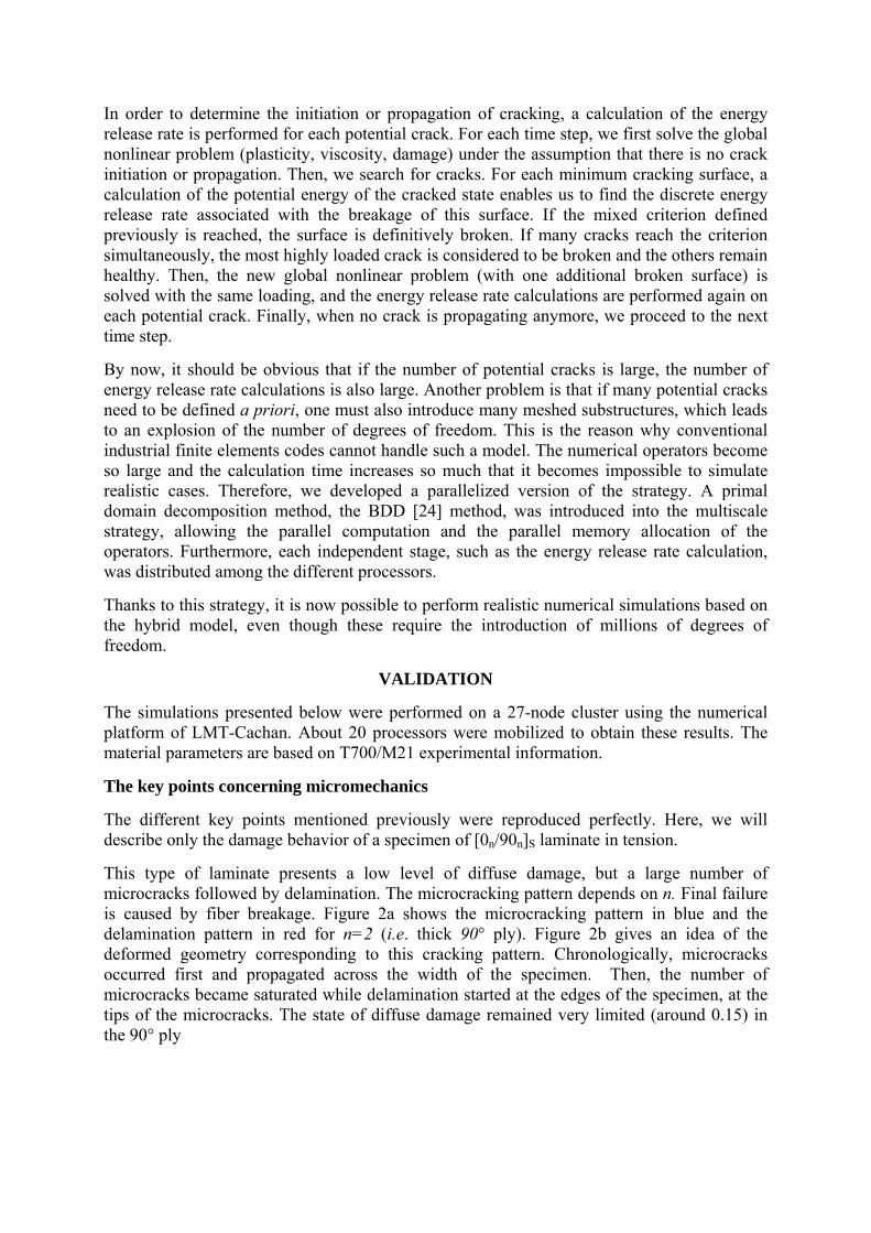
This type of laminate presents a low level of diffuse damage, but a large number of microcracks followed by delamination. The microcracking pattern depends on n. Final failure is caused by fiber breakage. Figure 2a shows the microcracking pattern in blue and the delamination pattern in red for n=2 (i.e. thick 90° ply). Figure 2b gives an idea of the deformed geometry corresponding to this cracking pattern. Chronologically, microcracks occurred first and propagated across the width of the specimen. Then, the number of microcracks became saturated while delamination started at the edges of the specimen, at the tips of the microcracks. The state of diffuse damage remained very limited (around 0.15) in the 90° ply
(a) crack pattern (b) deformed shape
Figure 5: Crack pattern of the simulated [02/902]S specimen in tension before fiber breakage
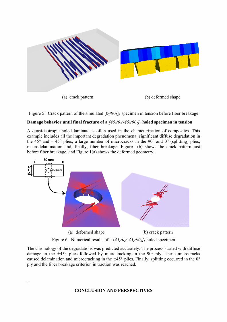
Damage behavior until final fracture of a [452/02/-452/902]S holed specimen in tension
A quasi-isotropic holed laminate is often used in the characterization of composites. This example includes all the important degradation phenomena: significant diffuse degradation in the 45° and – 45° plies, a large number of microcracks in the 90° and 0° (splitting) plies, macrodelamination and, finally, fiber breakage. Figure 1(b) shows the crack pattern just before fiber breakage, and Figure 1(a) shows the deformed geometry.
(a) deformed shape (b) crack pattern
Figure 6: Numerical results of a [452/02/-452/902]S holed specimen
The chronology of the degradations was predicted accurately. The process started with diffuse damage in the ±45° plies followed by microcracking in the 90° ply. These microcracks caused delamination and microcracking in the ±45° plies. Finally, splitting occurred in the 0° ply and the fiber breakage criterion in traction was reached.
.
CONCLUSION AND PERSPECTIVES
The hybrid micromodel presented here reproduces every observation on the micro, meso and macro scales.
Considering the computing cost necessary to perform calculations on realistic specimens, this model is not yet suitable for “virtual testing”, whose purpose is to simulate industrial structures. Nevertheless, this micromodel can be viewed as a database containing the most important information about the material. Furthermore, it constitutes what we call a “virtual reference material” combining information from a whole family of materials rather than from only a single material.
In practice, the mesomodel [25,26] used for the virtual testing application was the result of the homogenization of this hybrid computational damage micromodel, thanks to the micro-meso bridge developed in previous years [27,10,11].
References 1. P. Ladevèze: “Multiscale computational damage modeling of laminate composites”,
Course CISM Springer, p. 171-212, 2005.
2. P. Ladevèze, G. Lubineau and D. Violeau: “A computational damage micromodel of laminated composites”, Int. J. of Fract., Vol. 137, p. 139-150, 2006.
3. J. Nairn: “Matrix microcracking in composites”, in R. Taljera, J.A. Manson, editors. Polymer Matrix Composites, Vol. 2, p. 403-32, 2000.
4. C.T. Herakovich: ”Mechanics of Fibrous Composites”, J. Wiley & Sons, 1998.
5. J. Nairn, J. Hu: “The initiation and growth of delaminations induced by matrix microcracks in laminated composites“, Int. J. of Fract., Vol. 57, p. 1-24, 1992.
6. G.J. Dvorak, N. Laws : ”Analysis of progressive matrix cracking in composite laminates II. First ply failure”, J. of Comp. Mat., Vol. 21, p. 309-329, 1987.
7. P. Ladevèze, E. Le Dantec: ”Damage modeling of the elementary ply for laminated composites”, Comp. Sc. and Tech, Vol. 43, p. 257-267, 1992
8. O. Allix, P. Ladevèze: “Interlaminar interface modeling for the prediction of delamination”, Comp. Str., Vol. 22, p. 235-242, 1992
9. Z. Hashin: “Analysis of cracked laminates: a variationnal approach”, Mech. Mat., Vol. 4, p. 121-136, 1985.
10. D. Marsal, P. Ladevèze, G. Lubineau: “IUTAM Symposium on Multiscale Modeling of Damage and Fracture processes in Composite Materials. Section On the out-of-plane interactions between ply damage and interface damage in laminates”, Publisher Springer, Ed. T. Sadowski, p. 97-104 2006.
11. P. Ladevèze, G. Lubineau: ”On a damage mesomodel for laminates: micro-meso relationships, possibilities and limits”, Comp. Sc. and Tech., Vol. 61, p. 2149-2158, 2001.
12. J.M. Berthelot: “Transverse cracking and delamination in cross ply glass fibers and carbon fibers reinforced plastic laminates: static and fatigue loading”, Appl. Mech. Rev., Vol. 56, p. 1-37, 2003.
13. B. Sjogren, L. Berglund: “The effects of matrix and interface on damage in GRP cross-ply laminates cross-ply laminates“ Comp. Sc . and Tech., Vol. 60, p. 9-21, 2000.
14. F. Crossman, A. Wang: “The dependence of transverse cracking and delamination on ply thickness in graphite/epoxy laminates”, in Damage in Composite Materials, K.L. Reisfinder Ed, p. 118-139, 1982.
15. F.J. Guild, S.L. Ogin, P.A. Smith: ”Modeling of a 90° ply cracking in crossply laminates, including three-dimensional effects.”, J. of Comp. Mat., Vol. 27, p. 646-667, 1993.
16. Z. Hashin: “Finite thermoelastic fracture criterion with application to laminate cracking analysis”, J. Mech. Phys. Solids, Vol. 44(7), p. 1129-1145, 1996.
17. R.A. Schapery. A theory of nonlinear thermoviscoelasticity based on irreversible thermodynamics. Proceeding of the fifth US National Congress in Applied Mechanics, ASME, 511, 1966.
18. P. Ladevèze, G. Lubineau: “Fatigue in Composites, Science and technology of the fatigue response of fibre-reinforced plastics. Section A computational meso-damage model for life prediction for laminates”, Publisher Woodhead Publishing/CRC Press, Ed. B. Harris, 2003.
19. G. Lubineau, P. Ladevèze, D. Violeau: “ Durability of CFRP laminates under thermomechanical loading: A micro-meso damage model”, Comp. Sc. and Tech., Vol. 66(7/8), p. 983-992, 2006.
20. P. Ladevèze, O. Alix, J.F. Deu and D. Lévèque: “A mesomodel for localization and damage computation in laminates”, Comp. Meth. Appl. Mech. Eng., Vol. 61, p. 105-122, 2000.
21. P. Ladevèze, D. Néron, J.C. Passieux “On multiscale computational mechanics with time-space homogenization”, in Bridging the scales in Sciences and Engineering, J Fish (Ed.), Elsevier, 2008.
22. P. Ladevèze, O. Loiseau, D. Dureisseix: “A micromacro and parallel computational strategy for highly heterogeneous structures“, Int. J. for Num. Meth. in Eng., Vol. 52, p. 121–138, 2001.
23. D. Violeau, P. Ladevèze, G. Lubineau: “Micromodel-based simulations for laminated composites“, Comp. Sc. and Tech., doi :10.1016/j.compscitech.2008.09.041, 2008.
24. J. Mandel: “Balancing domain decomposition“. Comm. in Num. Meth. in Eng., Vol. 9, p. 233–241, 1993.
25. G. Lubineau , P. Ladevèze: ”Construction of a micromechanics-based intralaminar mesomodel, and illustrations in ABAQUS/Standard”, Comp. Mat. Sc., Vol. 43(17/18), p. 137-145, 2008.
26. P. Ladevèze, G. Lubineau: ”On a damage mesomodel for laminates: micromechanics basis and improvement”, Mech. of Mat, Vol. 35, p. 763-776, 2003.
27. P. Ladevèze, G. Lubineau, D. Marsal: “Toward a bridge between the micro and the mesomechanics of delamination for laminated composites”, Comp. Sci. and Tech., Vol. 66, p. 698,712, 2006.