Embed Size (px)
Citation preview

Available online at www.sciencedirect.com
t
ScienceDirect
Comput. Methods Appl. Mech. Engrg. 388 (2022) 114198www.elsevier.com/locate/cma
A multiscale high-cycle fatigue-damage model for the stiffnessdegradation of fiber-reinforced materials based on a mixed variational
frameworkNicola Maginoa, Jonathan Köblera, Heiko Andräa, Fabian Welschingerb, Ralf Müllerc,
Matti Schneiderd,∗
a Fraunhofer ITWM, Department of Flow and Material Simulation, Germanyb Robert Bosch GmbH, Corporate Sector Research and Advance Engineering, Germany
c University of Kaiserslautern, Institute of Applied Mechanics, Germanyd Karlsruhe Institute of Technology (KIT), Institute of Engineering Mechanics, Germany
Received 24 February 2021; received in revised form 27 August 2021; accepted 14 September 2021Available online xxxx
Abstract
Under fatigue-loading, short-fiber reinforced thermoplastic materials typically show a progressive degradation of the stiffnessensor. The stiffness degradation prior to failure is of primary interest from an engineering perspective, as it determines when
fatigue cracks nucleate. Efficient modeling of this fatigue stage allows the engineer to monitor the fatigue-process prior tofailure and design criteria which ensure a safe application of the component under investigation.
We propose a multiscale model for the stiffness degradation in thermoplastic materials based on resolving the fibermicrostructure. For a start, we propose a specific fatigue-damage model for the matrix, and the degradation of the thermoplasticcomposite arises from a rigorous homogenization procedure. The fatigue-damage model for the matrix is rather special, as itsconvex nature precludes localization, permits a well-defined upscaling, and is thus well-adapted to model the phase of stablestiffness degradation under fatigue loading. We demonstrate the capabilities of the full-field model by comparing the predictionson fully resolved fiber microstructures to experimental data.
Furthermore, we introduce an associated model-order reduction strategy to enable component-scale simulations of the localstiffness degradation under fatigue loading. With model-order reduction in mind and upon implicit discretization in time,we transform the minimization of the incremental potential into an equivalent mixed formulation, which combines two ratherattractive features. More precisely, upon order reduction, this mixed formulation permits precomputing all necessary quantities inadvance, yet, retains its well-posedness in the process. We study the characteristics of the model-order reduction technique, anddemonstrate its capabilities on component scale. Compared to similar approaches, the proposed model leads to improvementsin runtime by more than an order of magnitude.c⃝ 2021 The Authors. Published by Elsevier B.V. This is an open access article under the CC BY-NC-ND license
(http://creativecommons.org/licenses/by-nc-nd/4.0/).
Keywords: High-cycle fatigue damage; Stiffness degradation; Short-fiber reinforced materials; Generalized standard material; Model-orderreduction; Computational homogenization
∗ Corresponding author.E-mail address: [email protected] (M. Schneider).
https://doi.org/10.1016/j.cma.2021.1141980045-7825/ c⃝ 2021 The Authors. Published by Elsevier B.V. This is an open access article under the CC BY-NC-ND license (http://creativecommons.org/licenses/by-nc-nd/4.0/).

N. Magino, J. Kobler, H. Andra et al. Computer Methods in Applied Mechanics and Engineering 388 (2022) 114198
1
1
bme
m(mmtc
pa
. Introduction
.1. State of the art
To understand the complex failure behavior of structures made of fiber-reinforced composites, which mighte studied experimentally [1–3] or by simulative [4,5] means, it is imperative to account for the underlyingicrostructure. Indeed, the introduced fillers disturb the homogeneity of the material, giving rise to natural “notch”
ffects at the matrix–filler interfaces from which damage may evolve.We are interested in fiber-reinforced thermoplastic (SFRP) components under fatigue loading. Thermoplastic
aterials show a complex non-linear material behavior that depends on temperature, the processing conditionse.g., on crystallinity) and the loading rate [6,7]. For high-cycle fatigue of thermoplastic composites, in contrast toost polycrystalline materials, a significant decrease of the material stiffness is observed prior to the emergence ofacroscopic fatigue cracks [8]. This phenomenon is believed to be primarily driven by molecular rearrangements in
he matrix (e.g., crazing) and coalescing microcracks [9,10]. This decrease of stiffness is also observed in polymeromposites, and the level of stiffness loss is typically on the order of ten percent [11].
At high loading frequencies, the self-heating of the material leads to a thermally induced shift in the mechanicalroperties of the material [12]. Therefore, one usually restricts the load frequency to several Hz for the loadmplitudes typical for high-cycle fatigue [13,14]. The resulting temperature increase does not exceed 3–5 K [15],
so that thermally induced fatigue can be neglected. For mechanics-driven fatigue, the dependence of the materialbehavior on the frequency is less pronounced.
The most common damage mechanisms in short-fiber reinforced polymers are fiber fracture, fiber pull-out, matrixdamage and failure at the matrix–fiber interface [16]. Microvoids in the matrix are consistently reported to contributeto the material damage significantly [17–20]. Under fatigue loading, the number of microvoids increases not onlyin regions of high stress, such as at the fiber tips [17,20], but also in zones of low fiber density [20]. Startingfrom these microvoids, microcracks start to form at the fiber tips and alongside the fibers. Belmonte et al. [17]report these primary microvoids to form several tenths of a micrometer away from the matrix–fiber interface. Thisobservation indicates that matrix failure represents the dominant damage mechanism. Other authors report adhesivefracture at the interface (matrix–fiber failure) [18,19] or both failure modes [20]. These differences may be due todifferent chemical coatings used by the supplier to improve the fiber–matrix adhesion [17]. From a macroscopicperspective, several authors [21–24] identified three stages of evolving fatigue damage in thermoplastic composites.An initially rapid decrease of the stiffness is followed by a stable phase of fatigue-damage evolution, and a phaseof final failure.
Modeling strategies for the fatigue of polymer composites encompass phenomenological progressive damagemodels and physics-based progressive damage models. The former model damage growth based on macroscopicobservable properties and thus require extensive (typically rather costly) experimental studies [22–26]. The secondapproach accounts for fatigue effects on the microstructure, such as matrix damage, fiber fracture and matrix–fiber debonding, explicitly. The macroscopic material behavior emerges by homogenization in a natural way, seeMatous et al. [27] for a recent overview on computational homogenization methods. Mean-field techniques [28]for fatigue modeling of fiber reinforced polymers were developed by Krairi et al. [29] and Kammoun et al. [30].Moreover, Jain et al. [31,32] consider a master S/N-curve approach based on a mean-field model. More precisely,they account for damage on the microscopic scale via fiber–matrix debonding and assess final failure via a criterionbased on the amount of stiffness degradation, which is assumed to be independent of the fiber orientation. Jainet al. [31] reported their method to be fast, reliable and more accurate than established methods, e.g., based onempirical reduction coefficients [33–35] and rescaling based on the tensile strength [36–40]. These analyticalmethods are complemented by computational approaches. Developed for general two-scale problems, the FE2
method [41] associates a finite-element model of the microstructure to every integration point of the macroscale.In the context of damage in composite structures, the method was successfully applied [42,43]. To speed up thecomputations on the microscale, methods based on the fast Fourier transform (FFT) [44,45] were used to replacethe finite element models on the microscale, giving rise to the FE-FFT method [46–48], and applied to damage inshort-fiber reinforced composites [46]. To further reduce the computational burden of the simulations, model-orderreduction (MOR) strategies prove useful, like the transformation-field analysis of Dvorak and coworkers [49,50], itsnonuniform extension [51–53] and the self-consistent clustering analysis [54–56]. Alternatively, machine-learningmethods [57–63] may be used for multiscale simulations.
2

N. Magino, J. Kobler, H. Andra et al. Computer Methods in Applied Mechanics and Engineering 388 (2022) 114198
d
ttipMtim
1
oiods
[ip
scp
Fig. 1. Comparison of the effective fatigue damage reported in the literature [23] (left) and predicted by the proposed model (right),istinguishing constant strain amplitude (top) and constant stress amplitude (bottom) for reversible loading (i.e., R = 0).
Recently, Kobler et al. [64] proposed an efficient multiscale fatigue-damage model for short-fiber reinforcedhermoplastics based on a modification of classical phase-field fracture [65–67], combined with non-uniformransformation-field analysis (NTFA) [51–53] and fiber-orientation interpolation [68]. After an implicit discretizationn time, the incremental potential of the model is a fourth-order polynomial in the involved fields. In particular, arecomputation strategy could be used to speed up the online evaluation, enabling component-scale simulations. TheOR ansatz of Kobler et al. [64] and the mean-field approach of Jain et al. [31] share a common strategy. First,
he stable phase of fatigue damage is modeled. Then, a failure criterion based on the relative stiffness degradations utilized for predicting the fracture cycle. However, both articles differ in the computational approach to the
icroscale, with mean-field [31] and full field/MOR [68] models representing the different strategies.
.2. Contributions
This work builds upon the approach introduced by Jain et al. [31] and refined in Kobler et al. [64] in termsf a suitable multiscale fatigue-damage model of short-fiber polymer composites. Following their strategy, we arenterested in modeling the progressive stiffness degradation in the stable phase prior to failure, serving as the basisf a subsequent failure assessment via an appropriate criterion. To be more precise, we introduce a scalar fatigue-amage model for the polymer matrix, and the stiffness degradation of the composite arises from a suitable MORtrategy in a computational homogenization framework.
Kobler et al. [64] used a fatigue-damage model that is quite similar to classical phase-field fracture models65–67] and exploited the fact that the corresponding incremental potential is a fourth-order polynomial in thenvolved fields, which permits to express the incremental potential in a MOR framework exactly in terms of suitablerecomputed quantities. In particular, no special quadrature [69] is necessary in the NTFA procedure.
Taking a closer look at the typical stiffness degradation of polymer composites upon fatigue loading [21,23],ee Fig. 1, we notice that the first and the second phase of the fatigue-damage evolution on the macroscale areharacterized by a steady and stable damage evolution. Only for prescribed stress amplitude and in the third, final
¨
hase, localization occurs. As the models of Jain et al. [31] and Kobler et al. [64] only require modeling the3

N. Magino, J. Kobler, H. Andra et al. Computer Methods in Applied Mechanics and Engineering 388 (2022) 114198
fiaima
rst and the second phase of the fatigue-damage evolution to assess the lifetime of the component, we sought anlternative damage model which permits a more efficient numerical treatment. Indeed, to model this stable phase,t appears sufficient to employ a fatigue-damage model which avoids the negative side effects of softening damage
odels, like the inherently high number of modes necessary to capture the evolution in the strain softening regimeppropriately [64, Fig. 21] and the loss of representativity upon softening [70].
For this purpose, we build upon the convex, rate-independent damage model [71,72] of Gorthofer et al. [73].Inspired by the work of Govindjee [74], Gorthofer et al. [73] proposed a framework for damage models that directlyoperates on the compliance matrix as an internal variable and satisfies Wulfinghoff’s damage criterion [75]. Theresulting strain energy is jointly convex in the strain and internal variables and thus precludes strain softening [76],leading to mesh-independent results without the necessity of introducing a gradient term of the damage variable[77–83]. In contrast to elastoplastic models, which may be used for modeling a shift in the ”secant stiffness”, ourapproach permits to predict the degradation of the full stiffness tensor, accounting for anisotropy effects.
To reproduce the characteristic behavior of the fatigue-damage evolution in the first two stages, see Fig. 1, weformulate the model in the logarithmic cycle space. In addition to closely matching what is observed in experiments,see Fig. 1, this formulation leads to a high computational efficiency, as a large number of cycles can be simulatedquickly. Endowing the thermoplastic matrix with this model leads to a naturally emerging multiscale model, seeSection 2.2, which we demonstrate to be appropriate to capture the loss of stiffness upon fatigue loading for a glass–fiber reinforced polybutylene terephthalate (PBT), see Section 2.3, at least if the stiffness reduction introduced inthe initial phase, which can be determined experimentally with little effort, is considered.
Unfortunately, in its original form, the introduced fatigue-damage model is not directly suitable for efficientmodel-order reduction. In contrast to the model of Kobler et al. [64], the class of models introduced by Gorthoferet al. [73] leads to an incremental potential whose integrand is no longer a polynomial in the fields. In particular,the precomputing strategy of Kobler et al. [64] does not apply. Of course, approximation procedures [84,85],Gauss quadrature [69] or polynomialization [86] could be applied. To avoid the resulting decrease in accuracyor increase in computational effort, we follow a different route. More precisely, we exploit a reformulation of thefatigue-damage evolution in terms of the stress amplitude. Mathematically speaking, we apply a partial Legendretransform in the strain amplitude. By this nonlinear transformation, the underlying saddle-point problem has anincremental potential which is a third-order polynomial in the involved stress-amplitude and fatigue-damage field.In particular, the precomputation strategy of Kobler et al. [64] applies. However, this reformulation comes at acost. The original, primal minimization principle is replaced by a mixed variational principle, and its structureneeds to be studied anew, in particular concerning model-order reduction. Fortunately, see Section 3 for details, thecorresponding mixed variational principle turns out to be well-posed, even upon model-order reduction, as long assuitable (physically sound) conditions hold. We thoroughly investigate the sensitivity of the multiscale model andits reduced-order model w.r.t. the involved parameters in Section 4, and demonstrate the capabilities of the ensuingmodel on component scale, see Section 5.
2. A fatigue-damage model for the stiffness degradation
In Section 2.1, we introduce a (homogeneous) material model for the polymer matrix which models the stiffnessdegradation upon fatigue loading. The material model may appear simple, but was selected with its favorableproperties concerning model-order reduction in mind.
Kobler et al. [64] work directly in cycle space for reasons of efficiency. In a similar direction, we consider atime-like variable directly in logarithmic cycle space. We investigate the material behavior in a one-dimensionalstress- and strain-driven load case and compare the material behavior to fatigue degradation of short-fiber reinforcedpolymers reported in the literature [22,23,87]. Subsequently, in section 2.2, the described model enters as aconstituent in a composite, mathematically encoded by an appropriate first-order homogenization framework. Upondiscretization in cycle space and for prescribed stress (amplitude), we also discuss the naturally associated variationalprinciple. We close this section by showing that the introduced model captures the phase of second, stable stiffnessdegradation of fiber-reinforced composite microstructures quite accurately, at least if the initial stiffness degradation
is accounted for.4

N. Magino, J. Kobler, H. Andra et al. Computer Methods in Applied Mechanics and Engineering 388 (2022) 114198
2
ma
q
e
o
.1. Matrix modeling
We introduce a fatigue-damage material model at small strains using the framework of generalized standardaterials (GSMs) of dissipative solids [88,89]. We formulate our model in logarithmic cycle space, described bycontinuous variable N ≥ 0, instead of the more standard time framework. To be precise, we use the rescaling
N = log10 (N ) throughout this work, where N refers to the current cycle, and introduce a time like derivative′≡ dq/dN . This choice permits taking large steps △N in logarithmic cycle space, necessary for treating high-
cycle fatigue problems, instead of small time steps △t . The GSM framework is carried over to the cycle setting, bysimply relabeling the time t by the cycle N (some care has to be taken with the dimensions, as the time-like scaleN is dimensionless).
The proposed model involves a scalar damage variable d ≥ 0 as the only internal variable. We consider the freenergy
w (ε, d) =1
2 (1 + d)ε : C : ε, (2.1)
where ε refers to the elastic (small) strain tensor and C denotes the (undamaged) fourth-order stiffness tensor. Themodel is completed by the dissipation potential
φ(d ′)
=1
2α
(d ′)2
, (2.2)
where α > 0 determines the speed of evolution and d ′ denotes the derivative of the fatigue-damage variable d w.r.t.the continuous logarithmic cycle variable N . The associated Cauchy stress-tensor σ is defined by
σ ≡∂w
∂ ε(ε, d) =
1(1 + d)
C : ε, (2.3)
i.e., the stiffness tensor is reduced by a factor 1/ (1 + d) for growing fatigue-damage variable d . Biot’s equationassociated to the described model reads
0 !=
∂w
∂d(ε, d) +
∂φ
∂d ′
(d ′)
= −1
2 (1 + d)2 ε : C : ε +d ′
α, (2.4)
i.e., in explicit form
d ′=
α
2 (1 + d)2 ε : C : ε . (2.5)
As the right-hand side is always non-negative, the damage variable is non-decreasing for increasing cycles N .An implicit Euler discretization of Eq. (2.5) in logarithmic cycle space leads to the equation
dn+1− dn
△N=
α
2(1 + dn+1
)2 ε : C : ε, (2.6)
where dn refers to the damage value at the previous and dn+1 to the damage value at the current state.To gain some understanding of the predictions made by the model, we shall discuss uniaxial extension for the
ne-dimensional case in more detail. In this context, we denote the Young’s modulus by E .For a constant peak stress σmax, the differential equation (2.5) with initial condition d (0) = 0 may be integrated
exactly,
d(N)
=α
2σ 2
max
EN . (2.7)
Thus, the damage variable d grows linearly in the variable N . In Fig. 2(a), the solution is plotted for a stressamplitude of σmax = 25 MPa and the Young’s modulus E = 3 GPa. The fatigue-damage variable depends linearlyon the parameter α, resulting in a faster evolution of the damage variable d with increasing α. The damage variablehas no upper bound and evolves towards +∞ under fatigue loading. This corresponds to an asymptotic degradationof the effective stiffness Eeff
=1
1+d E towards zero,
Eeff=
11 2
E, (2.8)
1 + 2ασmax N/E5
N. Magino, J. Kobler, H. Andra et al. Computer Methods in Applied Mechanics and Engineering 388 (2022) 114198
d
e
zcs
mf
T
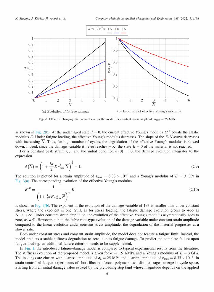
Fig. 2. Effect of changing the parameter α on the model for constant stress amplitude σmax = 25 MPa.
as shown in Fig. 2(b). At the undamaged state d = 0, the current effective Young’s modulus Eeff equals the elasticmodulus E . Under fatigue loading, the effective Young’s modulus decreases. The slope of the E-N -curve decreaseswith increasing N . Thus, for high number of cycles, the degradation of the effective Young’s modulus is slowed
own. Indeed, since the damage variable d never reaches +∞, the state E = 0 of the material is not reached.For a constant peak strain εmax and the initial condition d (0) = 0, the damage evolution integrates to the
xpression
d(N)
=
(1 +
3α
2E ε2
max N) 1
3− 1. (2.9)
The solution is plotted for a strain amplitude of εmax = 8.33 × 10⁻³ and a Young’s modulus of E = 3 GPa inFig. 3(a). The corresponding evolution of the effective Young’s modulus
Eeff=
1(1 +
32αE ε2
max N) 1
3E (2.10)
is shown in Fig. 3(b). The exponent in the evolution of the damage variable of 1/3 is smaller than under constantstress, where the exponent is one. Still, as for stress loading, the fatigue damage evolution grows to +∞ asN → +∞. Under constant strain amplitude, the evolution of the effective Young’s modulus asymptotically goes toero, as well. However, due to the cubic root-type evolution of the damage variable under constant strain amplitudeompared to the linear evolution under constant stress amplitude, the degradation of the material progresses at alower rate.
Both under constant stress and constant strain amplitude, the model does not feature a fatigue limit. Instead, theodel predicts a stable stiffness degradation to zero, due to fatigue damage. To predict the complete failure upon
atigue loading, an additional failure criterion needs to be supplemented.In Fig. 1, the introduced fatigue-damage model is compared to typical experimental results from the literature.
he stiffness evolution of the proposed model is given for α = 1.5 1/MPa and a Young’s modulus of E = 3 GPa.The loadings are chosen with a stress amplitude of σa = 25 MPa and a strain amplitude of εmax = 8.33 × 10⁻³. Instrain-controlled fatigue experiments of short-fiber reinforced polymers, two distinct stages emerge in cycle space.Starting from an initial damage value evoked by the preloading step (and whose magnitude depends on the applied
6

N. Magino, J. Kobler, H. Andra et al. Computer Methods in Applied Mechanics and Engineering 388 (2022) 114198
a
m
w
Fig. 3. Effect of the parameter α on the model for constant strain amplitude εmax = 8.33 × 10⁻³.
displacement [23]), the stiffness decreases rapidly in the first stage of fatigue loading. The proposed fatigue-damagemodel may reproduce the initial loss in stiffness by considering a positive initial value d0 > 0. If d0 = 0 is used,the stiffness degradation experienced in the first cycle will not be accounted for. The model at hand qualitativelyreproduces the rapid degradation of the material in stage-1 fatigue. Subsequently, in experimental stage-2 fatigue,the material degradation enters a stable phase of stiffness degradation. The effective Young’s modulus of the materialdecreases gradually. The model at hand may reproduce this fatigue-loading regime quite accurately.
Under constant stress-amplitude loading, the stiffness degradation is also characterized by these two phases, butenters a third stage, which was not observed for displacement-driven experiments. In this third stage, a criticaldamage state forms which leads to a complete fracture of the test specimen. This stage-3 fatigue is not accountedfor by the proposed fatigue model on the microscale. Rather, the onset of macroscopic failure can be determinedvia a suitable failure criterion, like a prescribed amount of stiffness lost [31,32,64].
2.2. Model on the microscale
Consider a cubic cell Y ⊆ Rm , and suppose that a microscopic stiffness distribution Y ∋ x ↦→ C (x), associating(non-degenerate) linear elastic stiffness tensor to each microscopic point, and a (bounded) field α : Y → [0, ∞),
are given. For a prescribed path of macroscopic stress amplitudes
Σ : [0, N max] → Sym(m), (2.11)
apping into the space Sym(m) of symmetric m × m tensors, we seek a displacement fluctuation field u, a strainfield ε, a stress field σ and a damage field d, all defined on the microscopic scale, satisfying kinematic compatibility
ε(N , x
)=⟨ε(N , ·
)⟩Y + ∇
su(N , x
), (2.12)
here ⟨.⟩Y stands for averaging over the cell Y , the constitutive equation
σ(N , x
)=
1(1 + d
(N , x
)) C (x) : ε(N , x
), (2.13)
the (quasi-static) balance of linear momentum
div σ(N , x
)= 0 (2.14)
7

N. Magino, J. Kobler, H. Andra et al. Computer Methods in Applied Mechanics and Engineering 388 (2022) 114198
a
t
t
f
F
aewi
ctptaw
2
rpro
Tapo
nd Biot’s equation
d ′(N , x
)=
α (x)
2(1 + d
(N , x
))2 ε(N , x
): C (x) : ε
(N , x
), (2.15)
ogether with the prescribed stress amplitude Σ(N)⟨
σ(N , ·
)⟩Y = Σ
(N)
(2.16)
and the initial condition
d (0, x) = 0 (2.17)
for all x ∈ Y . Upon an implicit discretization in time and eliminating all fields except for εn , un and dn , where themacroscopic strain εn at cycle N
nis defined as
εn=
⟨ε(
Nn, ·)⟩
Y, (2.18)
he latter set of equations, at the current cycle step, corresponds to a critical point of the variational principle
Fn+1 (ε, u, d) −→ min (2.19)
or the Ortiz–Stainier functional [90,91]
Fn+1 (ε, u, d) =
⟨1
2 (1 + d)
(ε + ∇
su)
: C :(ε + ∇
su)+
1
2α△N
(d − dn)2
⟩Y
− ε : Σ n+1. (2.20)
or the latter definition, we use the convention that Fn+1 (ε, u, d) = +∞ if α (x) = 0 and d (x) = dn (x) forx ∈ Y . Also, the short-hand notation Σ n
= Σ(
Nn)
is used.For the article at hand, we are primarily interested in the evolution of the effective stiffness upon fatigue loading.
The latter arises from the local stiffness tensor field C/ (1 + d) by linear elastic homogenization [92].If C is uniformly positive and bounded and α is bounded as well, it is not difficult to see that the problem (2.20)
dmits a unique minimizer in a suitable Sobolev space [93]. Indeed, eliminating the damage variable d via Biot’squation (2.6) leads to a strictly convex optimization problem in the strain field, whose condensed energy growsith an exponent between 4/3 and 2 in the strain, depending on whether α vanishes or not. Once the strain field
s obtained, the (square-integrable) damage field may be recovered via Biot’s equation.Thus, the presented model is well-defined for Sobolev spaces with exponents larger than one. In particular, by
onstruction, no damage localization is permitted by the mathematical model. Indeed, such localization behavior isypically observed for energies with linear growth in the strain. The superlinear growth of the condensed energyrecludes localization. Thus, focusing on the stable fatigue damage regime, see stage-1 and stage-2 fatigue in Fig. 1,he presented damage model comes with a beneficial numerical treatment, as it leads to mesh-independent resultslso without gradient enrichment. Physically speaking, the model at hand monitors the phase of stiffness decreasehich does not (yet) have fracture mechanical ramifications. This contrasts with comparable models [64].
.3. Parameter identification
After discussing the ability of the model to reproduce the typical fatigue-damage behavior of short-fibereinforced polymers in the one-dimensional case, see Section 2.1, this section is devoted to identifying the single freearameter α, which governs the speed of fatigue-damage growth for the model at hand. We compare experimentalesults to simulations on representative volume elements (RVE) to determine this parameter. Moreover, the capabilityf the model to reproduce the stiffness decrease is further discussed.
We performed experiments on specimens made of polybutylene terephthalate (PBT) reinforced by E-glass fibers.he isotropic elastic moduli for these materials are given in Table 1. The elastic properties of the E-glass fibersre standard, whereas the elastic properties of the polymer matrix were identified via quasi-static testing of theure matrix material using so-called Becker samples, see [94], on a Zwick universal testing machine. We restricturselves to stress ratios
R =Σmin (2.21)
Σmax8

N. Magino, J. Kobler, H. Andra et al. Computer Methods in Applied Mechanics and Engineering 388 (2022) 114198
Fig. 4. Setup and geometries for experiments.
Fig. 5. Comparison of experimental data and simulation results.
Table 1Model parameters adjusted to experimental data.
Material E in GPa ν Additional parameters
E-glass fibers 72 0.22 –PBT matrix 2.69 0.4 α = 15 1/GPa
of R = 0 throughout this work.The specimens used for the fatigue tests were cut from an injection-molded plate as shown in Fig. 4(a). Each
specimen has a thickness of 2 mm and the geometric properties of the specimens are shown in Fig. 4(b).The fatigue tests were performed on a Schenk hydropulser as shown in Fig. 4(c). With respect to time-efficient
testing, the frequencies of the experiments were chosen in the range from 2 Hz to 12 Hz depending on the loadingamplitudes. Of course, induced self-heating of the samples limits the maximum frequency that can be applied. Thechosen frequency ensures that the temperature increase during testing, measured at the sample surface, does notexceed 2 K. For the positioning of the temperature sensor on the sample, see Fig. 4(c). The local deformation inthe middle of the sample is recorded using extensometers with a gauge length l0 = 10 mm, see Fig. 4(c).
In accordance with the literature [18,23,87], the experiments show an initial rapid decrease of the stiffness forlow cycles and a secondary steady regime in the linear cycle space, see Fig. 5(a). The strain results are normalizedby a reference strain ε0, more precisely ε0 = εxx (N = 0) at a stress amplitude of 60 MPa. This decrease correspondsto a linear evolution when displayed in logarithmic cycle space, see Fig. 5(b).
9

N. Magino, J. Kobler, H. Andra et al. Computer Methods in Applied Mechanics and Engineering 388 (2022) 114198
tt
t
sw
For parameter identification using numerical computations on representative volume elements, it is necessaryo characterize the fiber orientation state of the experimental specimens. Thus, the microstructural properties ofhe specimens were examined via high-resolution X-ray microcomputed tomography (µCT) analysis. For details
of the characterization process, we refer to Hessman et al. [3]. The fiber volume content was found to be 17.8%.The identified aspect ratio depends on the segmentation algorithm and the chosen batch. The algorithm proposedby Hessman et al. [3] predicts an aspect ratio of 26.1, whereas the aspect ratio obtained from the commercialSimpleware ScanIP software is 23.9. As such small changes in the fibers’ aspect ratio have little influence on theeffective material behavior, we use the aspect ratio of 25 for the numerical simulations throughout this work.
The fiber orientations in these specimens show a layered structure over the thickness. To keep the proceduresimple, we consider a homogeneous, averaged fiber orientation and compute the second-order Advani–Tucker tensorfrom the scan over the complete specimen thickness. The second-order Advani–Tucker fiber-orientation tensorA [95] is computed from the fiber directions pi ∈ S := {p ∈ R3, ∥p∥ = 1} via the formula
A =1
Nfiber
Nfiber∑i=1
pi ⊗ pi . (2.22)
The obtained eigenvalues in the specimens are λ1 = 0.770, λ2 = 0.213 and λ3 = 0.017. We use these parameterso generate the microstructure in Fig. 4(d) by the sequential addition and migration algorithm [96].
Subsequently, the microstructure shown is subjected to uni-axial extension in the principal fiber direction at theame stress amplitudes that were used in the experiment. We identified the parameter α = 0.015 1/MPa. In Fig. 5,e compare the measurements to numerical experiments for using a log-cycle scale N .For the stress amplitudes at hand, the strain evolution curves are captured quite well by the model. Both the
slopes of the strain evolution as well as the initial strain amplitude, corresponding to the strain amplitude at thefirst cycle, are captured. However, for computations at higher or lower stress amplitudes than shown here, the initialstrain amplitudes at the first cycle deviate from the experimental results. This kind of initial stiffness decrease inthe first few cycles prior to stage-1 fatigue shown in Fig. 1(b) is not accounted for by the proposed model.
For the work at hand, we focus on the region between initial damage (or plastic deformation) and fracture,namely stage-1 and stage-2 fatigue. The prediction of the initial strain amplitude decrease is left for subsequentwork.
The damage evolution in the fatigue damage region between initial loading and final fracture has been observedto be of logarithmic character. The formulation of the model at hand in log-cycle space N is thus reasonable.
3. A model-order reduction strategy based on a mixed formulation
3.1. A reformulation in terms of the stress
In the previous section we formulated our model based on the Ortiz–Stainier potential (2.20)
F (ε, u, d) =
⟨1
2 (1 + d)
(ε + ∇
su)
: C :(ε + ∇
su)+
1
2α△N
(d − dn)2
⟩Y
− ε : Σ , (3.1)
where we drop the superscript n+1 for this section. This formulation is not ideally suited for model-order reduction.For a basis of preselected modes, we would like to express the functional to be minimized in terms of quantitiesthat can be precomputed, avoiding any access to full fields. However, such a precomputation is not possible, as thedamage variable d enters the denominator in the Ortiz–Stainier potential. Instead of relying upon an approximation,for instance by a Taylor polynomial [69,84,85], we follow a different route.
Let us invert the stress–strain relationship (2.3) of the matrix model,
ε = (1 + d) S : σ (3.2)
in terms of the compliance tensor S = (C)−1. Similarly, we may recast Biot’s equation (2.5) in the form
d ′=
α
2σ : S : σ, or,
d − dn
△N=
α
2σ : S : σ (3.3)
upon an implicit Euler discretization in logarithmic cycle space. With precomputations useful for model-order
reduction in mind, this reformulation is very convenient. Indeed, Eqs. (3.2) and (3.3) involve only terms that are10

N. Magino, J. Kobler, H. Andra et al. Computer Methods in Applied Mechanics and Engineering 388 (2022) 114198
j
v
iFr
a
s
a
w
i
a
Ni
ointly quadratic in the internal variables (σ, d). A lower degree of homogeneity in the joint internal variables isfavorable for precomputations, as this degree affects the number of the precomputed system matrices in the reducedorder model, see Section 3.2.
As for the primal model, see section equations (2.1) and (2.2), we may establish a (mixed) variational principle
S (σ, d) −→ mind
maxdiv σ=0⟨σ ⟩Y =Σ
(3.4)
in terms of the saddle-point function
S (σ, d) =
⟨−
(1 + d)
2σ : S : σ +
1
2α△N
(d − dn)2
⟩Y
. (3.5)
The equivalence of the strain- and the stress-based formulations, (2.19) and (3.4), respectively, in terms of therelation (3.2) is shown in Appendix A. However, some care has to be taken with this formulation. Please notice thatthe function S is always convex in d, but concavity in σ is only ensured for d ≥ −1. Thus, instead of the formalmixed variational principle (3.4), it is recommended to fix some d− ∈ (−1, 0] and to consider the constrained mixedariational principle
S (σ, d) −→ mind≥d−
maxdiv σ=0⟨σ ⟩Y =Σ
(3.6)
nstead. Please notice that the considered mixed variational principle differs from the mixed variational principle ofritzen–Leuschner [53]. Indeed, we perform a partial Legendre transform in the strain, whereas Fritzen–Leuschnerely upon a partial Legendre transform in the internal variable.
Suppose that Md damage modes
δa : Y → R, a = 1, . . . , Md , (3.7)
nd Mσ stress modes
si : Y → Sym(m), i = 1, . . . , Mσ , (3.8)
atisfying
⟨si ⟩Y = 0 and div si = 0, i = 1, . . . , Mσ , (3.9)
re given. Then, for M = (Mσ , Md), and coefficients
d =(d1, . . . , dMd
)∈ RMd and σ =
(σ1, . . . , σMσ
)∈ RMσ , (3.10)
e consider the reduced-order model determined by the mixed variational principle (3.6)
SM
(σ , d
)−→ min
d, d≥d−
maxσ
(3.11)
nvolving the function
SM
(σ , d
)≡ S (σ, d) with σ = Σ +
Mσ∑i=1
σi si and d =
Md∑a=1
daδa, (3.12)
nd where the previous cycle step is represented in the form
dn=
Md∑a=1
dna δa for a suitable dn
∈ RMd . (3.13)
otice that, in the reduced-order setting, it is not readily apparent that the problem (3.11) is solvable, and that theres a unique solution. For this purpose, let us introduce the non-linear operator
Mσ Md Mσ Md
AM : R ×R → R ×R , (3.14)11
N. Magino, J. Kobler, H. Andra et al. Computer Methods in Applied Mechanics and Engineering 388 (2022) 114198
i
hf
dt
urs
Sr
mplicitly defined via⟨AM
(σ β, dβ
),(σ γ , dγ
)⟩M
=⟨(1 + dβ
) (Σ + σ β
): S : σ γ
+1
α△N
(dβ
− dn) dγ−
12
dγ(Σ + σ β
): S :
(Σ + σ β
)⟩Y
,
for any(σ β, dβ
),(σ γ , dγ
)∈ RMσ ×RMd , where we use the abbreviations
σ κ=
Mσ∑i=1
σ κi si as well as dκ
=
Md∑a=1
dκa δa for κ ∈ {β, γ } (3.15)
and the inner product⟨(σ β, dβ
),(σ γ , dγ
)⟩M
=
⟨Mσ∑
i, j=1
σβ
i σγ
j si : s j +
Md∑a,b=1
dβa dγ
b δaδb
⟩Y
(3.16)
on the space RMσ ×RMd . The operator (3.14) is closely related to the mixed variational principle (3.11) and (3.12).Indeed, AM may be written in the form
AM
(σ , d
)=
(−
∂SM
∂σ,∂SM
∂ d
). (3.17)
Thus, any saddle point(σ , d
)of the mixed variational principle (3.11) which satisfies d > d− is a root of the
operator AM . Conversely, any root(σ , d
)of the operator AM is a saddle point of the variational principle (3.11).
Of course, the same holds with the gradient of the function SM in place of the operator AM . However, the simple signreversal (3.17) in the first component provides the operator AM with better properties. Indeed, with the abbreviations(3.15), the identity⟨
AM
(σ β, dβ
)− AM
(σ γ , dγ
),(σ β, dβ
)−
(σ γ , dγ
)⟩M
=⟨2 + dβ
+ dγ
2
(σ β
− σ γ)
: S :(σ β
− σ γ)+
1
α△N
(dβ
− dγ)2⟩
Y(3.18)
olds for any(σ β, dβ
),(σ γ , dγ
)∈ RMσ × RMd . Suppose that the stiffness distribution C is uniformly bounded
rom above and from below
c− ε : ε ≤ ε : C (x) : ε ≤ c+ ε : ε, x ∈ Y, ε ∈ Sym(m), (3.19)
with positive constants c±, and let α+ be an upper bound for α. Then, under the condition dκ≥ d− for κ ∈ {β, γ },
the identity (3.18) implies the estimate⟨AM
(σ β, dβ
)− AM
(σ γ , dγ
),(σ β, dβ
)−
(σ γ , dγ
)⟩M
≥
c− (1 + d−)⟨(σ β
− σ γ)
:(σ β
− σ γ)⟩
Y +1
△Nα+
⟨(dβ
− dγ)2⟩Y
. (3.20)
In particular, as d− > −1, the operator AM is strongly monotone, and the monotonicity constant does notepend on the chosen bases. We refer to Appendix B for a derivation of the identity (3.18). By similar arguments,he identity⟨
AM
(σ , d
),(σ , d
)⟩M
=
⟨1 + d
2(Σ + σ) : S : σ +
1
α△N
(d − dn) d
⟩Y
, (3.21)
sing the abbreviations (3.15), may be deduced. Hence, the operator AM is also coercive. Moreover, due to itsepresentation by a polynomial, the operator AM is continuous. Thus, as long as the constraint d ≥ d− > −1 isatisfied, classical monotone operator theory [97] implies that there is a unique root of the operator AM .
For our computational experiments, it was not necessary to enforce the constraint d ≥ d− explicitly, seeection 4.3.1. Thus, the latter constraint may be regarded as a theoretical prerequisite that may not always beequired in practice.
12

N. Magino, J. Kobler, H. Andra et al. Computer Methods in Applied Mechanics and Engineering 388 (2022) 114198
3
ms
atd
w
i
wrlFf
ie
wc
f
it
.2. Implementation and solution of the discretized system
The proposed fatigue model permits a straightforward model-order reduction. Thus, precomputations on theicroscale can be completed once and for all in an offline phase. The derivation of macroscopic equations and
ystem matrices from the POD modes are discussed in this section.The polynomial character of the saddle point functional (3.12) permits this saddle point functional, considered as
function of the mode coefficients, to be precomputed exactly (up to numerical precision). In particular, no access tohe full fields is required during the online evaluation of the proposed multiscale fatigue-damage model. Let us firstiscuss why a polynomial potential enables a precomputation strategy. Suppose a function f of a vectorial variable
z is given. We assume the variable z to be finite-dimensional with dimension Mz , and denote the components of z byzi , reserving Latin indices i, j, k for this purpose. Suppose furthermore that a number of modes za (a = 1, . . . , Mm)
ere selected, and we seek an approximation
z =
Mm∑a=1
ξa za (3.22)
n terms of suitable mode coefficients ξa (a = 1, . . . , Mm). In particular, we are interested in the function
f (ξ1, . . . , ξMm ) = f
(Mm∑a=1
ξa za
), (3.23)
hich only depends on the mode coefficients. For MOR to be effective, the number of mode coefficients Mm in theepresentation (3.23) should be much smaller than the number of vector components Mz . For general functions f ,ittle is gained by considering the function f (3.23), as its definition follows the indirect way via the variable z.or polynomial functions f , in contrast, a different strategy can be followed. For concreteness, let us assume theunction f to be a polynomial of degree 3, i.e., it may be expressed in the form
f (z) = C +
Mz∑i=1
fi zi +
Mz∑i, j=1
fi j zi z j +
Mz∑i, j,k=1
fi jk zi z j zk (3.24)
n terms of suitable coefficients C , fi , fi j and fi jk . Then, inserting the mode representation (3.23), we obtain thexpression
f (ξ1, . . . , ξMm ) = C +
Mm∑a=1
fa ξa +
Mm∑a,b=1
fab ξaξb +
Mm∑a,b,c=1
fabc ξaξbξc, (3.25)
hich turns out to be a third-order polynomial in the mode coefficients and involves the precomputableoefficients
fa =
Mz∑i=1
fi zai ,
fab =
Mz∑i, j=1
fi j zai zb
j ,
fabc =
Mz∑i, j,k=1
fi jk zai zb
j zck
(3.26)
or a, b, c = 1, . . . , Mm .Let us return to the fatigue-damage model at hand. For fixed modes (3.7) and (3.8), we set z = (σ , d),
.e., Mz = Mσ + Md , and consider the objective function f =SM (3.12), which is a third-order polynomial inhe unknowns. Similar to the representation (3.25) involving the quantities (3.26), we obtain an expression of the
13

N. Magino, J. Kobler, H. Andra et al. Computer Methods in Applied Mechanics and Engineering 388 (2022) 114198
o
FFf
wsSoSvm
a
totfdawsusrt
bjective function SM in the form
SM
(σ , d
)= −
12Σ : ⟨S⟩Y : Σ − Σ : Πiσi −
12
Si jσiσ j
−12Σ : Da : Σ da − Σ : Λiaσi da −
12
Ti jaσiσ j da
+1
2α△NDabdadb −
1
α△NDabdadn
b +1
2α△NDabdn
a dnb .
(3.27)
rom Eq. (3.27) onwards, we use Einstein’s summation convention, i.e., we sum over pairs of appearing indices.or clarity, we reserve the indices a and b for damage modes, i.e., they sum from one to Md , and use i as well as jor the stress modes, summing from one to Mσ . In the expression (3.27), the following quantities are precomputed:
Πi = ⟨S : si ⟩Y ,
Si j =⟨si : S : s j
⟩Y ,
Da = ⟨δaS⟩Y ,
Λia = ⟨δaS : si ⟩Y ,
Ti ja =⟨δasi : S : s j
⟩Y ,
Dab = ⟨δaδb⟩Y ,
(3.28)
here the appearing indices have the same range as above. Notice also that all appearing quantities in (3.28) areymmetric in the index pairs (a, b) and (i, j), respectively. To increase notational clarity, we use a Greek letter forym(m)-valued objects, Roman letters for scalar-valued objects and double stroke letters for fourth order tensorbjects. The memory consumption for precomputing the quantities (3.28) is O
(Md M2
σ
). As already mentioned in
ection 3.1, the evolution equations of the proposed damage model (3.2), (3.3) are jointly quadratic in the internalariables. For a Galerkin-discretization using constant POD-modes the highest complexity in the precomputedatrices is thus in the order of three. Here, for Md = O (Mσ ), the array Ti ja has the highest complexity with
Md × Mσ (Mσ + 1) /2 independent components.Saddle points of the function SM (3.27) satisfy the balance of linear momentum
Si jσ j + Σ : Λiada + Ti jaσ j da = −Σ : Πi (i = 1, . . . , Mσ ) (3.29)
nd Biot’s equation
1
α△NDabdb −
1
α△NDabdn
b =12Σ : Da : Σ + Σ : Λiaσi +
12
Ti jaσiσ j (a = 1, . . . , Md) . (3.30)
Please notice that, if the macroscopic strain ε is specified instead of the macroscopic stress Σ , the equation
⟨S⟩Y : Σ + Πiσi +Da : Σ da + Λiaσi da = ε (3.31)
needs to be added to the system in order to determine Σ .For the convenience of the reader, an overview of offline and online computation is given in Fig. 6: Based on
he fiber orientation interpolation concept [68], a finite number of fiber orientations is chosen. For each of theserientations, a short-fiber microstructure is generated [96]. For specified material parameters of matrix and fiber,he fatigue-damage evolution is computed using an FFT-based solver and a number of load cases, see Section 4.1or details. Using the resulting solution fields, stress and damage modes are extracted via proper orthogonalecomposition (POD). More precisely, the damage and stress full-field solutions for all precomputed load casesnd either all or a subset of cycle steps (see Section 4.3.2 for a study) are stored on disk. For a microstructureith N 3 voxels, this amounts to storing N 3 or 6 × N 3 double-precision floating-point numbers per (damage or
tress) snapshot, corresponding to either one or six scalars per voxel. Then, the POD correlation matrices are setp based on the L2 inner product both for the fatigue-damage variable and the stress field, and the damage andtress modes are extracted by the usual eigenvalue thresholding [98,99], see Section 4.3 for a study. Eventually, theelevant system matrices (as discussed in this section) are precomputed, and the model is ready for application onhe component scale.
14

N. Magino, J. Kobler, H. Andra et al. Computer Methods in Applied Mechanics and Engineering 388 (2022) 114198
o
Jc
4
og
Fig. 6. Concept of precomputations and online phase.
Table 2Properties of the generated microstructures and the spatial discretization.
Parameter Value Unit
Fiber length 250 µmFiber diameter 10 µmAspect ratio 25 –Fiber-volume content 17.8 %Minimum fiber distance 5 µmAverage voxels per diameter 6.4 –Cell length/fiber length 2.4 –
For solving Eqs. (3.29), (3.30) and (3.31), we use Newton’s method with backtracking. For strongly monotoneperators, the latter scheme converges quadratically. As the termination condition for the scheme, we use
∥∇S∥!
≤ 10−8∥ε∥, (3.32)
where we chose the Frobenius norm for the strain-amplitude tensor.
4. Computational investigations
4.1. Setup
The multiscale fatigue model described in Section 2.2 is discretized in time via an implicit Euler scheme and ona staggered grid in space [100]. For resolving the balance of linear momentum, we rely upon a nonlinear conjugategradient method [101] to reduce the strain-based residual suggested in Kabel et al. [102] below a tolerance of 10−5.
The material model was implemented as a user subroutine in the FFT-based software FeelMath [103] and inulia [104], which also served as the environment for the model-order reduction. For the computations, a Linuxluster equipped with Intel Xeon Gold 1648 processors was used.
.2. Microscale studies
To study the material behavior on the microscale, we introduce three reference structures with different fiberrientations: an isotropic structure, a planar-isotropic structure and a unidirectional structure. The structures were
enerated by the sequential addition and migration algorithm (SAM) [96] using the parameters listed in Table 2.15

N. Magino, J. Kobler, H. Andra et al. Computer Methods in Applied Mechanics and Engineering 388 (2022) 114198
a
r
4
uwsYDa
i
a
Fig. 7. Reference microstructures with different fiber orientations.
The resulting reference structures are shown in Fig. 7, visualized with GeoDict.1 The SAM algorithm permitsachieving high accuracy for the second-order fiber-orientation tensors. For example, for the isotropic and the planarisotropic microstructures shown in Fig. 7, the realized second-order fiber-orientation tensors read
A(2)iso =
⎡⎣ 0.333334 −9.65272 × 10⁻⁸ 4.43788 × 10⁻⁷
−9.65272 × 10⁻⁸ 0.333333 2.71964 × 10⁻⁸
4.43788 × 10⁻⁷ 2.71964e × 10−8 0.333333
⎤⎦ (4.1)
nd
A(2)piso =
⎡⎣ 0.499739 −0.000526419 −4.66944 × 10⁻⁶
−0.000526419 0.499739 7.31379 × 10⁻⁶
−4.66944 × 10⁻⁶ 7.31379 × 10⁻⁶ 0.000521332
⎤⎦ , (4.2)
espectively.
.2.1. On the necessary spatial resolutionFor a start, we investigate the resolution that is necessary to obtain mesh-insensitive results. As our reference, we
se 6.4 voxels per fiber diameter to resolve a fiber and call the respective voxel size h, see Table 2. Subsequently,e increase and decrease the resolution by a factor of two and compare the effective properties obtained from
imulations on these structures to simulations on the reference structure. In Fig. 8, the evolution of the effectiveoung’s moduli [105] for the selected fiber orientations under uni-axial extension in x- and z-direction are shown.ue to the direction independence of the isotropic microstructure, only extension in x-direction is considered. For
ll three fiber orientations, the effective Young’s moduli are plotted in x- and z-direction.We introduce the error measure
eYoung= 2 max
i
∥E1(N i ) − E2(N i )∥
∥E1(N i ) + E2(N i )∥(4.3)
to quantify the deviation between two Young’s modulus evolutions E1 and E2. For the isotropic structure, thedeviation between the 2 × h-discretization and the 0.5 × h-discretization is 1.01% in x-direction and 1.21%n z-direction in terms of the stiffness-based error measure (4.3). Comparing the h-discretization and the 0.5 ×
h-discretization, the errors are below 0.5%, i.e., 0.25% in x-direction and 0.32% in z-direction.For the planar-isotropic orientation, the observations are similar. For the unidirectional structure, the deviations
t the 2 × h discretization are even less pronounced. Indeed, the unidirectional microstructure under loading in x-direction shows an error of 0.20% in x-direction and 0.01% in z-direction, when comparing the 2×h discretizationto the 0.5 × h discretization in terms of the stiffness-based error measure (4.3). Under loading in z-direction, thedeviation is 0.20% in x-direction and 0.06% in z-direction.
1 Math2Market GmbH, http://www.geodict.de.
16

N. Magino, J. Kobler, H. Andra et al. Computer Methods in Applied Mechanics and Engineering 388 (2022) 114198
Fig. 8. Influence of the mesh size on the computational results.
Since the error measure (4.3) stays below 1% for all discussed load cases and directions, compared the h- to the2 × h-discretization, we consider the deviation of the h discretization from the 2 × h discretization acceptable, andfix the mesh spacing to h for all subsequent studies.
4.2.2. On the necessary resolution in log-cycle spaceAs a second verification step on the microscale, we investigate the necessary step size △N in logarithmic cycle
space. For an implicit Euler discretization with uniform step sizes △N ∈ {0.05, 0.1, 0.2}, results are shown in Fig. 9.Please notice that the logarithmic cycle variable N is dimensionless.
The results show that the model turns out to be rather robust w.r.t. the chosen cycle step size. Even a step sizeof 0.2 produces only small errors. We fix a constant step size of 0.1 for the succeeding investigations.
4.2.3. On the necessary size of the unit cellAfter studying the necessary resolution per fiber and the necessary step size, we turn our attention to the necessary
size of the considered unit cell to produce representative results. Please keep in mind that the convexity of the modelpermits classical homogenization theory [92] to be applicable, see Section 2.2. In particular, the emergence of aneffective material response on representative volume elements [70,106] is ensured, in contrast to the closely relatedmodel of Kobler et al. [64].
17

N. Magino, J. Kobler, H. Andra et al. Computer Methods in Applied Mechanics and Engineering 388 (2022) 114198
Fl
Fig. 9. Necessary resolution in logarithmic cycle space.
As our reference, we use volume elements with of 3843 voxels, see Table 2. To study necessity and sufficiencyof this fixed size, we increase and decrease the unit cell to comprise 2563 and 5123-voxels, respectively. The arisingedge length of the unit cells are 3.2 fiber lengths and 1.6 fiber lengths.
The evolving effective Young’s moduli are shown in Fig. 10, where we restrict to those cases with highest errors.We observe non-negligible deviations of the effective properties obtained from the 1.6 fiber length structures to thoseof the 3.2 fiber length structures for all considered loading scenarios. Comparing the Young’s modulus evolution ofthe 2563-voxel volume element to the 5123-voxel volume element, the stiffness-based error measure (4.3) is of theorder of several percent for the considered load cases, with the highest error observed in the evolution of the Young’smodulus body of the planar-isotropic structure. For the planar-isotropic structure under loading in x-direction, thedeviation reaches 3.0% in x-direction; for loading in z-direction, the deviation is 2.6% in x-direction. In particular,the volume element with 2563 voxels fails to be representative.
Comparing the predictions for the 3843-structure, encompassing 2.4 fibers per edge, to the predictions of thelarger volume size with 5123 voxels and an edge length of 3.2 fiber lengths, these deviations decrease. For theisotropic and unidirectional structures, the errors of the Young’s modulus evolution under loading in x- and z-direction are smaller than 1.0%. The most critical case is the planar-isotropic structure under loading in x-direction.In this case, the deviation of the predicted Young’s modulus evolution in x-direction is 1%. This deviation is wellwithin limits of engineering accuracy and we consider the 3843 structure to be representative for the model at hand.
or the remainder of the manuscript, we fix the size of the volume elements to be of an edge length of 2.4 fiberengths.
18

N. Magino, J. Kobler, H. Andra et al. Computer Methods in Applied Mechanics and Engineering 388 (2022) 114198
atwfvsH
Fig. 10. Dependence of the computational results on the size of the unit cell.
4.2.4. Fields on the microscaleTo gain some understanding of the local fields on the microscale, we discuss the evolution of the damage and
the strain field for the isotropic case under loading in x-direction. We load the structure shown in Fig. 7(b) at aconstant stress amplitude of σmax = 100 MPa.
The resulting damage and maximum principal strain fields in the x–y-plane are shown in Fig. 11. Taking a lookt the damage evolution, we observer that, in the early stages, damage is initiated at the fiber tips. Subsequently,he damage spreads through the structure. At the last cycle shown in Fig. 11(c), damage evolved also close to fibershich are oriented perpendicular to the loading direction. The maximum reduction of the stiffness locally reached
or the isotropic structure under a load amplitude of 100 MPa in x-direction is 33%. This corresponds to a damagealue of d = 0.5. The loss of the homogenized Young’s modulus of the complete RVE in load direction at this timetep is 10% and thus well in the order of typical stiffness loss in short fiber reinforced polymers prior to failure [31].igher loading amplitudes lead to more pronounced damage.The strain evolution, starting from cycle N = 10 (N = 1) up to cycle N = 107 (N = 7), is shown in the bottom
row in terms of the maximum principal strain. The evolution of the strain closely corresponds to the damage fieldevolution. In particular, it does not show localization. As for the damage field, the strain increases mainly at thetips of fibers oriented in loading direction. However, there are no microcrack-like patterns evolving throughout thematrix. Rather, the damage effects only lead to increasingly large strains at these critical spots.
4.3. Reduced-order model
We investigate the capability of the reduced model to approximate the full-field solution in this section. For thesake of brevity, we use the isotropic, the planar isotropic and the unidirectional structure, shown in Fig. 7, for thesestudies. For each of the structures, we precomputed the load cases listed in Table 3. For assessing the accuracy of thereduced-order models, a strain-based error measure is introduced. For our stress driven simulations, the predictedeffective (peak) strains of the full-field simulation εmax and the reduced-order model εrom
max are compared in terms ofthe error measure
erom=maxi
(εmax(N i ) − εrommax(N i )
εmax(N i )
). (4.4)
19

N. Magino, J. Kobler, H. Andra et al. Computer Methods in Applied Mechanics and Engineering 388 (2022) 114198
l
4
s
iatitc
mr
m
Table 3Tensor components of the stress amplitude (in MPa) for precomputed load cases used for database generation.
load case Σmaxxx Σmax
yy Σmaxzz Σmax
yz Σmaxxz Σmax
xy
# 1 100 MPa 0 0 0 0 0# 2 0 100 MPa 0 0 0 0# 3 0 0 100 MPa 0 0 0# 4 0 0 0 100 MPa 0 0# 5 0 0 0 0 100 MPa 0# 6 0 0 0 0 0 100 MPa
Fig. 11. Local stiffness reduction (1 − 1/(1 + d) ≡ d/(1 + d), top) and maximum principal strain (bottom) on the isotropic structure underoading in x-direction.
.3.1. Mode selectionFor selecting the modes of the reduced-order model, we investigated different strategies. In the end, the simplest
trategy turned out to be the most powerful, and we shall report on it in the following.Please recall that the continuous model discussed in Section 2.1 is uniquely solvable (upon implicit discretization
n cycle space) and is characterized by a damage variable which can only grow point-wise. In the mixed formulationnd upon a Galerkin discretization, see Section 3.1, these properties needed to be re-evaluated. It turned out thathe mixed formulation is theoretically well-posed provided a lower bound d− (strictly greater than d = −1) ismposed on the damage field. Indeed, under this assumption, the operator whose roots correspond to solutions ofhe discretized equations turns out to be strongly monotone, and classical monotone-operator theory implies thelaim.
For the study at hand, we use classical proper orthogonal decomposition (POD) for extracting damage and stressodes from the precomputed load cases. We chose the number of stress and damage modes to be identical, and
efer to this number briefly as the number of modes.Please note that working with the lower bound d− is only sufficient for obtaining a well-posed model, and
ay be unnecessary in practice. Indeed, imposing such a constraint a priori may induce significant computational
20

N. Magino, J. Kobler, H. Andra et al. Computer Methods in Applied Mechanics and Engineering 388 (2022) 114198
o
oeist
cTFAoms
apIa
mroT
4
ct
Fig. 12. Minimum value of the reconstructed damage field for the unidirectional structure under shear in the yz-plane for different numbersf incorporated modes Mσ .
verhead. Also, for our computational experiments, the reduced-order model could be solved rapidly and robustlyven without additionally imposed constraints. The reasons behind this surprising behavior is studied more closelyn the following. For this purpose, we reconstruct the damage fields predicted by the reduced-order model byumming the mode coefficients multiplied by their precomputed and stored damage modes at each step and extracthe minimum damage-value from the corresponding full damage field.
The evolution of the minimum damage-value was computed for all load cases listed in Table 3. The most criticalase in terms of the damage minimum for seven incorporated modes is the unidirectional structure under load case 4.he minimum damage-value evolution for this case is shown in Fig. 12 for different numbers of incorporated modes.or seven and eight modes, the minimum damage-value of the reconstructed damage field is d = −2.92 × 10−3.lbeit negative, this value is far from d = −1. By increasing the number of modes incorporated into the reduced-rder model, the minimum damage-value increases. This does not come unexpected. Indeed, the reduced-orderodel approximates the full-field prediction with higher accuracy. The full-field prediction, on the other hand,
atisfies the constraint d ≥ 0 by construction, see Section 2.1.For 15 modes, the minimum damage-value is larger than d = −3.5×10⁻⁴ for all load cases listed in Table 3 and
ll considered microstructures. Using 15 modes thus appears sufficient to inherit the well-posedness and stabilityroperties from the continuous model. We continue with discussing the accuracy of the mode-selection procedure.n Fig. 13, the strain error (4.4) is shown vs. the number of incorporated modes for the isotropic, the planar isotropicnd the unidirectional structure, respectively.
In general, the results of the reduced-order model agree well with the full-field predictions. Incorporating sixodes into the reduced-order model already leads to a strain error below 1% for all load cases computed on the
espective structures. Load cases with expected similar effective response, e.g., extension in x-direction, y-directionr z-direction for the isotropic structure (load cases 1, 2 and 3, respectively), show similar approximation behavior.his is remarkable, as we did not account for this symmetry explicitly in the mode-selection procedure.
We will use 15 POD-modes in the reduced-order model subsequently.
.3.2. Number of snapshots per pathTo identify stress and damage modes, we use proper orthogonal decomposition. Some care has to be taken
oncerning the number of snapshots used for each considered loading path. We discuss the necessary choice forhe number of snapshots per loading path (NSPL) in this section.
We use equidistant sampling steps in the logarithmic cycle variable N . For the sake of brevity, we only discuss theplanar-isotropic case here. The other fiber orientations lead to similar qualitative and quantitative results. The effectof including a different number of snapshots is shown in Fig. 14. We observe that the capability of the reduced-ordermodel to approximate the effective strain amplitude predicted by the full-field model does not strongly depend onthe chosen number of snapshots. Indeed, the strain-amplitude error (4.4) is in the same order of magnitude at all
number of modes in Fig. 14 regardless of the number of snapshots (NSPL). Even a model order reduction based21

N. Magino, J. Kobler, H. Andra et al. Computer Methods in Applied Mechanics and Engineering 388 (2022) 114198
oN
dtr
ctti
ft
d
Fig. 13. Accuracy study for the database generated from ten snapshots per loading path.
Fig. 14. Influence of the Number of Snapshots Per Loading path (NSPL) for the planar-isotropic structure (see Fig. 7(b))
on as few as three snapshots per load path appears to be reasonable. This appears to be a consequence of thenon-localizing nature of the fatigue-damage model.
However, if the number of snapshots is chosen too small, the number of extractable modes is limited. On thether hand, the achieved approximation quality is certainly limited by choosing too few modes. Therefore, we fixSPL= 10. An extension to more snapshots does not seem necessary and is thus omitted for the sake of faster
precomputations.
4.3.3. Necessary loading paths for database generationIn this section, we investigate the capabilities of the reduced-order model to predict the effective stiffness
egradation for loading scenarios that were not accounted for in the database generation. More precisely, we discusswo variants: a change of the loading direction and a change of the loading amplitude. For the sake of brevity, weestrict to the planar-isotropic structure.
We start with the effect of changing the loading direction. We consider load cases of pure extension at theonstant stress amplitude of Σmax
xx = 100 MPa and stress ratio R = 0. The material parameters are chosen accordingo Table 1. First, we study loading in x-direction. Additionally we consider an extension at a 45◦ angle aroundhe z-axis. Due to the symmetry of the planar-isotropic microstructure, both loading scenarios should give rise todentical responses (up to a rotation).
We consider a database built upon the load cases listed in Table 3, referred to as standard database in theollowing. Note that the first load case is part of the database. The enriched database comprises, in addition tohe load cases of the standard database, the 45◦-rotated full-field prediction.
The results of the reduced-order models for these two load cases, both, for the standard database and the enriched
atabase, are plotted in Fig. 15. The Young’s modulus computed from the full-field prediction is referred to as Efull22

N. Magino, J. Kobler, H. Andra et al. Computer Methods in Applied Mechanics and Engineering 388 (2022) 114198
f
i
bsm
Fig. 15. Deviation of the direction-dependent Young’s modulus from the full-field prediction in the x–y-plane for the planar-isotropic structureor different databases.
Table 4Strain-amplitude errors (4.4) for changing loading amplitude.
Strain errors for loading in
Σmaxxx Σmax
zz Σmaxyz Σmax
xy
20 MPa 1.1 × 10⁻⁵ 6.0 × 10⁻⁶ 1.3 × 10⁻⁶ 9.8 × 10⁻⁷
100 MPa 1.3 × 10⁻⁵ 1.3 × 10⁻⁵ 2.6 × 10⁻⁶ 4.1 × 10⁻⁶
500 MPa 9.2 × 10⁻² 3.9 × 10⁻² 2.9 × 10⁻³ 9.2 × 10⁻²
and the Young’s modulus computed from the reduced-order model as Erom. The error measure (Efull − Erom)/Efull
s plotted over a range of 180◦ in the x–y-plane, where 0◦ corresponds to the x-axis and 90◦ to the y-axis.We observe that the first load case, extension in x-direction, leads to a negligible relative error of about 0.1%,
oth, for the standard and the enriched database. On the contrary, when considering the 45◦-rotated load case, thetandard database is not able to reproduce the load case with the same accuracy. At an angle of 135◦, the Young’sodulus at N predicted with the standard database deviates from the full-field prediction by a relative error of
1.4%. Yet, the induced error remains on an acceptable level.When including the 45◦-oriented extension load-case into the precomputations, the accuracy of the reduced-order
model is increased. Both load cases, tension in x-direction and tension in 45◦ are predicted with similar accuracyin the order of 0.1%.
As a take-away message from these studies, we state that some caution has to be taken regarding a discretizationof the space of possible loadings to select the modes from. Yet, the standard sampling with six load cases appearsreasonable in terms of accuracy. To increase the accuracy, the sampling strategy could be extended in an adaptiveway. For the work at hand, we fix the standard six load cases.
As a second step in studying the necessary precomputations, we investigate the effect of varying the loadingamplitude. We restrict the computational examples to the planar-isotropic structure. Recall that precomputationswith a peak stress Σmax
xx = 100 MPa are used to generate the database, see Table 3. For this study, we multiplythese load amplitudes by factors of 5 and 0.2, respectively. Simulations at a peak stress of Σmax
xx = 500 MPa wellexceed typical stress values in fatigue experiments and are only chosen here to test the capability of the numericalmodel to adapt to stress amplitudes higher than the training level. For the load cases with modified amplitudes,we compute the strain-amplitude error (4.4) by comparison of the full-field to the reduced-order model predictions.
The results are shown in Table 4.23

N. Magino, J. Kobler, H. Andra et al. Computer Methods in Applied Mechanics and Engineering 388 (2022) 114198
ia1tsε
iotWo
Tiscb2efaa
Fig. 16. Stiffness and strain results for planar-isotropic structure under 500 MPa loading: comparison of full-field predictions and reduced-ordermodel.
Table 5Strain-amplitude errors (4.4) for changing loading amplitude, trained at 20MPa.
Strain errors for loading in
Σmaxxx Σmax
zz Σmaxyz Σmax
xy
20 MPa 2.9 × 10⁻⁵ 3.5 × 10⁻⁵ 4.1 × 10⁻⁵ 4.2 × 10⁻⁵
100 MPa 1.4 × 10⁻³ 6.3 × 10⁻⁴ 7.1 × 10⁻⁴ 2.0 × 10⁻³
500 MPa 1.1 × 10⁻¹ 6.2 × 10⁻² 8.6 × 10⁻³ 2.4 × 10⁻¹
We observe that the load case with Σmaxxx = 20 MPa, which is smaller than the training load case Σmax
xx = 100 MPancluded into the database, is predicted accurately with strain-amplitude errors below 10−4. For a higher amplitudet Σmax
= 500 MPa, the accuracy decreases significantly. We observe a maximum error of 9.23% in load casesand 6. In Fig. 16(a), the strain amplitudes computed by the full-field model and the reduced-order model for
his load case are shown in more detail. Up to strains of 0.13 in loading direction, the deviation of the full-fieldtrain curve to the reduced-order model predictions is small. Indeed, at N = 1.8, where the full-field model predictsa,xx = 0.128, the reduced-order model predicts εa,xx = 0.130, which is a relative deviation of 1.6%. For furtherncreasing strain amplitudes, the deviation between the effective strain-amplitude curve of the full-field model andf the reduced-order model increases, as well. In addition to the strain amplitude, we investigate the evolution ofhe Young’s modulus body. For load case 1, the Young’s modulus body in the x–z-plane is plotted in Fig. 16(b).
e observe that, even though the magnitude is not accurately met, the reduced-order model still predicts the shapef the Young’s modulus body in accordance with the full-field solution, also at high cycle numbers.
Unexpectedly, despite being trained at 100 MPa, the database is most accurate for a stress amplitude of 20 MPa.o understand this effect more thoroughly, we trained a database with lower load amplitudes of 20 MPa and compare
ts accuracy to the standard database, trained at 100 MPa. We compare the errors produced by the 20 MPa database,ee Table 5, to those of the standard database in Table 4. The most critical load case at an amplitude of 20 MPaan be reproduced with an accuracy of 2.9 × 10⁻⁵, which has the same order of magnitude as the error producedy the 100-MPa database for the same load case of 1.1 × 10⁻⁵. In contrast, the 100 MPa load cases treated by the0-MPa database cannot be reproduced with the same accuracy as for the 100-MPa database. Indeed, the maximumrror increases from 1.3×10⁻⁵ to 2.0×10⁻³, which corresponds to a loss in accuracy by a factor of 154. The trendor even higher load amplitudes of 500 MPa is similar. This investigation reveals that the fatigue-damage evolutiont lower stress amplitude is easier to approximate – as a result of the underlying physics – than at higher stress
mplitudes. This is the reason for the higher accuracy of the 100 MPa database for a stress amplitude of 20 MPa.24

N. Magino, J. Kobler, H. Andra et al. Computer Methods in Applied Mechanics and Engineering 388 (2022) 114198
Fig. 17. Accuracy study on the fiber-orientation triangle: strain error (4.4) at precomputed and interpolated structures.
We conclude that the model may be safely used for computations where the strain evolution reaches strain levelsof the training level or below, but some caution is advised when exceeding the pre-training levels. This effect is aconsequence of the non-linearity of the model. It was with this insight at hand that we selected a training amplitudeof 100 MPa, as the reasonable stress amplitudes of interest are covered in this way. Despite some deviations in thepredicted effective strain amplitudes, the effective stiffness of the reduced-order model is predicted rather accurately.
4.3.4. Covering different fiber orientation statesWith component-scale applications in mind, a variety of fiber-orientation states needs to be considered. Guided
by the state of the art in injection-molding simulations [4], we consider a varying second-order fiber-orientationtensor [95] as the input for the generated microstructures. To create a database encompassing all possible second-order fiber-orientation tensors, we utilize the fiber-orientation interpolation procedure proposed by Kobler et al. [68].Up to an orthogonal transformation, second-order fiber-orientation tensors may be parameterized by a two-dimensional triangle, corresponding to the two largest eigenvalues of the second-order fiber-orientation tensor.Based on a triangulation of this fiber-orientation triangle, a reduced-order model is identified for every node ofthis triangulation. Subsequently, the effective models are interpolated to the entire triangle. We refer to Kobleret al. [68] for details.
We discretize the fiber-orientation triangle by 15 nodes as shown in Fig. 17, resulting in 16 sub-triangles. For eachof the 15 nodes, we generate microstructures and precompute all six load cases listed in Table 3 for these structures.These precomputations are then used to build a database via proper orthogonal decomposition, as described inSection 4.3. In a first verification step, we compare the evolution of the strain amplitude predicted by the full-fieldcomputations on these 15 structures with the predictions of the reduced-order model by means of the error measure(4.4). In Fig. 17(a), this error measure is plotted at each of the nodes for the reference load cases (lc) , see Table 3.The accuracy on the precomputed structures is good for all microstructures and all considered load cases. Themaximum observed strain-amplitude error is 1.8 × 10⁻⁴ for the structure with eigenvalues λ1 = 0.417, λ2 = 0.417and λ3 = 0.167 under extension in x-direction (load case 1). We observe the errors in the extension load cases to behigher than the errors in the shear cases. The accuracy using 15 modes is sufficient for the precomputed structures.Note that the choice of 15 modes arises from the study on the non-negativity of the damage field, see Section 4.3.1.In terms of the accuracy choosing even fewer modes would be reasonable.
As a second verification step, we investigate the predictions of the model on fiber orientation states that havenot been precomputed directly, but are interpolated from nearby precomputed states. For these structures withinthe faces of the discretized fiber-orientation triangle, as suggested by Kobler et al. [68], we compute the materialresponse of the surrounding structures at the nodes of the discretized fiber-orientation triangle via the reduced-ordermodel, and successively interpolate the effective stresses. This procedure increases the effort by a factor of three,both, in terms of CPU time and memory usage, as, for each Gauss point, three material laws have to be evaluated.
To assess the predictive capabilities of the interpolation procedure, we generated microstructures at the centroidsof the 16 sub-triangles. The computed (full-field) effective strain-amplitude tensors serve as our reference. We
25

N. Magino, J. Kobler, H. Andra et al. Computer Methods in Applied Mechanics and Engineering 388 (2022) 114198
Fig. 18. Relative degradation of the acoustic tensor (5.1) after 106 cycles.
compare these effective strain amplitudes to the effective strain amplitudes predicted by the reduced-order modelvia interpolation in terms of the error measure (4.4). In Fig. 17(b), we observe that the strain errors do not exceed5 % in the maximum strain-amplitude error. Since nodal errors are found to be very small, the latter error is mainlycaused by the interpolation procedure. For the remainder of this work, we will use the presented fiber-orientationtriangulation.
5. Component-scale simulations
We demonstrate the numerical capabilities of the presented model on component scale in terms of efficiency inboth computational and memory usage by comparison to the recently published approach of Kobler et al. [64]. Thismodels differs from the one presented in this work mainly in two aspects.
1. Non-local/local: The approach of Kobler et al. [64] introduces a damage-gradient term to avoid mesh-dependent results. The model proposed in this work is well-defined without an additional damage-gradientterm.
2. Polynomial order: The highest polynomial order in the variables (σ, d) in Eqs. (3.2) and (3.3) is two, whereasthe approach by Kobler et al. [64] leads to polynomials of the order of three in (ε, d). Thus, less data needsto be processed at the Gauss point level for the former model.
In contrast to the approach presented in the work at hand, the model of Kobler et al. [64] permits localization,which makes the choice of the snapshots for proper orthogonal decomposition more difficult. Indeed, choosing anequidistant sampling method, Kobler et al. [64] incorporate 40 strain and 40 damage modes to reach acceptableaccuracy. As discussed in Section 4.3, we make use of only 15 stress and 15 damage modes to ensure that thedamage field is accurately captured.
We chose to demonstrate the efficiency of the model at hand on the same component and load case as describedin Kobler et al. [64]: a short-fiber reinforced motor-housing subjected to fatigue loading. For details on the fiber-orientation distribution inside the component, as well as on the load case, we refer to Kobler et al. [64]. We usethe simulation software ABAQUS [107] for computations on the macroscale. Both computations were performedon the same Linux cluster with 256 CPUs distributed on 16 nodes up to the cycle 106.
Similar to Kobler et al. [64], we chose the determinant of the acoustic tensor Aaco as a quantitative measure forthe material degradation and define
Λ(N ) = max∥n∥=1
[1 −
det Aaco(n,C(N ))det Aaco(n,C(0))
], (5.1)
where n denotes a unit-normal vector, to assess the current damage state in the macroscopic model. The damagestate of the motor housing component after 106 cycles is shown in Fig. 18 for, both, the quadratic type damagemodel of Kobler et al. [64] (Fig. 18(a)) and the compliance-based damage model proposed in the work at hand
26

N. Magino, J. Kobler, H. Andra et al. Computer Methods in Applied Mechanics and Engineering 388 (2022) 114198
tbT
tt
Table 6Computational effort for the considered fatigue-damage models.
CPU time max. memory usage av. memory usage
Quadratic damage model [64] 12200 h 65.5 GB 47.4 GBCompliance based damage 712 h 39.0 GB 22.9 GB
(Fig. 18(b)). The regions of critical damage evolution, i.e., regions with a high relative decrease in the maximumof the acoustic tensor determinant, are found to be similar for both models.
The CPU time and the memory usage are shown in Table 6. Both, in terms of CPU time and memory usage,he efficiency of the model at hand is improved compared to the previous work. The CPU time of the complianceased damage model at hand leads to a speed up by a factor of 17 compared to the quadratic damage model [64].he memory usage is on average improved by 52% and the peak memory usage by 40%.
This gain has three main causes. For a start, a lower number of incorporated modes is used, which decreaseshe size of the system matrices. Secondly, the polynomial in the damage evolution and stress–strain relationship inerms of the internal variables is of lower order. Thirdly, in contrast to Kobler et al. [64], we use a local model and
do not have to incorporate gradient terms. The last two factors decrease the number of system matrices which needto be precomputed and stored.
6. Conclusions
We considered the problem of fatigue-damage evolution in short-fiber reinforced polymer composites. In order toaccount for the influence of the fiber reinforcements, both, in terms of the fiber geometry and the fiber orientation,we proposed a multiscale model for the fatigue-damage evolution in the stable second phase. The principal objectof interest for us is the anisotropic stiffness degradation of such composites when subjected to (high-cycle) fatigueloading. Indeed, the failure behavior of thermoplastic components under fatigue loading appears to be difficult topredict if the stiffness decrease under fatigue loading previous to failure is not accounted for.
Motivated by the stability of the second phase in the fatigue-damage evolution, we explored the recentlyintroduced class of damage models based on the compliance tensor [73]. Indeed, the inherent convexity of themodel class appears sufficient for representing the fatigue-damage phenomena of interest, and offer to alleviate thecomputational burden associated to damage models with gradient extension [78].
We showed that, despite its simplicity, the model matches our experimental results rather well, provided theinitial damage occurring in the first few cycles is taken into consideration. The precise value of the initial damagerequires further studies.
With upscaling in mind, we studied a mixed formulation of the incremental potential of the multiscale fatigue-damage model. In this formulation, the potential is a third-order polynomial in the mode coefficients, and thuslends itself naturally to an efficient model-order reduction. Surprisingly, we could show that this mixed formulationinherits well-posedness from the purely primal formulation by rewriting the mixed formulation in terms of a specificoperator, which is strongly monotone under a natural condition on the damage field.
The multiscale fatigue-damage model was tested thoroughly, both as a full-field and as a reduced-order model.Due to the (strongly) convex nature of the model, emergence of effective properties via suitable representativevolume elements [106] is guaranteed. Also, due to the precluded localization, the multiscale model is characterizedby high computational efficiency, which could be demonstrated on component scale.
This work was mainly concerned with setting up the multiscale technology necessary to handle industrial-scaleapplications. As a next step, it appears imperative to account for the initial damage caused in the first few cyclesby an appropriate modification of the model and to investigate the extension to R-values different from zero as wellas the dependence on the loading frequency. Supplemented by an appropriate failure criterion on the macroscopicscale, the presented multiscale fatigue-damage model will be ready for applications.
Declaration of competing interest
The authors declare that they have no known competing financial interests or personal relationships that could
have appeared to influence the work reported in this paper.27

N. Magino, J. Kobler, H. Andra et al. Computer Methods in Applied Mechanics and Engineering 388 (2022) 114198
A
T(
r
A
t
t
cknowledgments
MS acknowledges financial support of the German Research Foundation (DFG) within the International Researchraining Group “Integrated engineering of continuous–discontinuous long fiber reinforced polymer structures”GRK 2078).
We would like to thank Egon Moosbrugger for the experimental work. We are grateful to the anonymouseviewers, whose constructive remarks led to a significant improvement of the manuscript.
ppendix A. Derivation of the saddle-point problem
We wish to establish the equivalence of minimizing the Ortiz–Stainier potential (2.20)
F (ε, u, d) =
⟨1
2 (1 + d)
(ε + ∇
su)
: C :(ε + ∇
su)+
1
2α△N
(d − dn)2
⟩Y
− ε : Σ (A.1)
and the variational principle (3.4)
S (σ, d) ≡
⟨−
(1 + d)
2σ : S : σ +
1
2α△N
(d − dn)2
⟩Y
−→ mind
maxdiv σ=0⟨σ ⟩Y =Σ
(A.2)
in terms of the relationship (3.2)
ε = (1 + d) S : σ. (A.3)
This appendix provides a derivation based on convex duality. More precisely, suppose a convex function f : X → R
is given on a Banach space X . Let f ∗: X ′
→ R be its Legendre transform
f ∗(y) = supx∈X
⟨x, y⟩ − f (x), (A.4)
where ⟨·, ·⟩ denotes the natural pairing ⟨·, ·⟩ : X × X ′→ R. Suppose that a closed subspace U ⊆ X is given, and
let U ∗⊆ X∗ be its annihilator
U ∗= {y ∈ X∗
| ⟨y, x⟩ = 0 for all x ∈ U }. (A.5)
Then, according to convex duality [108, Thm. 31.4], the identity
minx∈U
f (x) = − miny∈U∗
f ∗(y) (A.6)
holds. For the problem at hand, we consider the space X to consist of square-integrable strain (or stress) fields onhe unit cell Y , and we consider the objective function
f (ε) =
⟨1
2 (1 + d)ε : C : ε +
1
2α△N
(d − dn)2
⟩Y
− ⟨ε⟩Y : Σ , (A.7)
reating the damage variable d as a parameter, and work on the subspace of kinematically compatible strains
U ={ε ∈ X | ε = ε + ∇
su for some ε and u}. (A.8)
The Legendre transform of the function (A.7) computes as
f ∗(τ ) =
⟨(1 + d)
2(Σ + τ) : S : (Σ + τ) −
1
2α△N
(d − dn)2
⟩Y
(A.9)
in terms of the compliance S = C−1. Indeed, the Legendre dual (A.4) is defined in terms of a maximization principle
f ∗(τ ) = supε∈X
⟨τ : ε⟩Y −
⟨12
ε : C : ε +1
2α△N
(d − dn)2
⟩Y
+ ⟨ε⟩Y : Σ , (A.10)
whose critical points ε ∈ X satisfy
τ − C : ε +Σ = 0, i.e., ε = S : Σ + τ . (A.11)
( )28

N. Magino, J. Kobler, H. Andra et al. Computer Methods in Applied Mechanics and Engineering 388 (2022) 114198
H
id
w
A
ere, we set
C =1
1 + dC and S = (1 + d)S (A.12)
for notational brevity. Inserting the explicit expression for the strain field ε into the definition (A.10) yields
f ∗(τ ) =
⟨τ : S : (Σ + τ)
⟩Y
−
⟨12
(Σ + τ) : S : (Σ + τ) +1
2α△N
(d − dn)2
⟩Y
+
⟨Σ : S : (Σ + τ)
⟩Y
=
⟨(Σ + τ) : S : (Σ + τ)
⟩Y
−
⟨12
(Σ + τ) : S : (Σ + τ) +1
2α△N
(d − dn)2
⟩Y
=
⟨12
(Σ + τ) : S : (Σ + τ) −1
2α△N
(d − dn)2
⟩Y
,
(A.13)
i.e., the representation (A.9) emerges. To complete the picture, we note that the orthogonal complement2 U ∗ takesthe form
U ∗= {τ ∈ X | ⟨τ ⟩Y = 0 and div τ = 0} , (A.14)
.e., it consists of equilibrium stress fluctuations. Combined with the expression (A.10), we conclude by convexuality (A.6) that we may transform
minε,u
⟨1
2 (1 + d)
(ε + ∇
su)
: C :(ε + ∇
su)+
1
2α△N
(d − dn)2
⟩Y
− ε : Σ
= − mindiv τ=0⟨τ ⟩Y =0
⟨(1 + d)
2(Σ + τ) : S : (Σ + τ) −
1
2α△N
(d − dn)2
⟩Y
= − mindiv σ=0⟨σ ⟩Y =Σ
⟨(1 + d)
2σ : S : σ −
1
2α△N
(d − dn)2
⟩Y
= maxdiv σ=0⟨σ ⟩Y =Σ
⟨−
(1 + d)
2σ : S : σ +
1
2α△N
(d − dn)2
⟩Y
,
(A.15)
where we introduced the total stress field σ = Σ + τ . Moreover, the identification (A.11) turns into
ε = (1 + d)S : σ. (A.16)
Last but not least, we further minimize over the damage field to conclude
minε,u,d
⟨1
2 (1 + d)
(ε + ∇
su)
: C :(ε + ∇
su)+
1
2α△N
(d − dn)2
⟩Y
− ε : Σ
= mind
maxdiv σ=0⟨σ ⟩Y =Σ
⟨−
(1 + d)
2σ : S : σ +
1
2α△N
(d − dn)2
⟩Y
,
(A.17)
hat was to be shown.
ppendix B. Monotonicity of the operator AM
In this appendix, we wish to derive the identity (3.18)⟨AM (σ β, dβ) − AM (σ γ , dγ ), (σ β, dβ) − (σ γ , dγ )
⟩M
=
⟨2 + dβ
+ dγ
2(σ β
− σ γ ) : S : (σ β− σ γ ) +
1
α△N(dβ
− dγ )2⟩
Y.
(B.1)
For fixed compliance tensor S and dn, α ∈ R, we investigate the operator
A : Sym(m) ×R → Sym(m) ×R, (σ, d) ↦→
((1 + d)S : σ, α−1(d − dn) −
12σ : S : σ
)(B.2)
2 As we are working in a Hilbert space, we may canonically identify the dual space with the primal Hilbert space, and exchange theannihilator by the orthogonal complement, both in view of Riesz’ representation theorem.
29

N. Magino, J. Kobler, H. Andra et al. Computer Methods in Applied Mechanics and Engineering 388 (2022) 114198
F
I
Rc
R
or any (σ β, dβ), (σ γ , dγ ) ∈ Sym(m) ×R≥0, we observe[A(σ β, dβ) − A(σ γ , dγ )
](σ β
− σ γ , dβ− dγ ) =
[(1 + dβ)S : σ β
− (1 + dγ )S : σ γ]
: (σ β− σ γ )
+ α−1(dβ− dγ )2
−12
(σ β: S : σ β
− σ γ: S : σ γ )(dβ
− dγ ).
(B.3)
ntroducing the short-hand notation dκ= 1 + dκ , κ ∈ {β, γ }, we transform[
dβ S : σ β− dγ S : σ γ
]: (σ β
− σ γ ) −12
(σ β: S : σ β
− σ γ: S : σ γ )(dβ
− dγ )
= dβ σ β: S : σ β
− (dβ+ dγ ) σ β
: S : σ γ+ dγ σ γ
: S : σ γ
−12
(dβσ β: S : σ β
− dβσ γ: S : σ γ
− dγ σ β: S : σ β
+ dγ σ γ: S : σ γ )
=12
dβ σ β: S : σ β
− (dβ+ dγ ) σ β
: S : σ γ+
12
dγ σ γ: S : σ γ
+12
(dβσ γ: S : σ γ
+ dγ σ β: S : σ β)
=12
(dβ+ dγ ) (σ β
: S : σ β− 2 σ β
: S : σ γ+ σ γ
: S : σ γ )
=dβ
+ dγ
2(σ β
− σ γ ) : S : (σ β− σ γ ).
(B.4)
Inserting this result back into the original formula, we obtain[A(σ β, dβ) − A(σ γ , dγ )
](σ β
−σ γ , dβ−dγ ) =
2 + dβ+ dγ
2(σ β
−σ γ ) : S : (σ β−σ γ )+α−1(dβ
−dγ )2. (B.5)
egarding C, α = α △N and dn as dependent on x ∈ Y , averaging the latter identity proves the formula (B.1), aslaimed.
eferences[1] Y. Lee, S. Lee, J. Youn, K. Chung, T. Kang, Characterization of fiber orientation in short fiber reinforced composites with an image
processing technique, Mater. Res. Innov. 6 (2002) 65–72.[2] H. Shen, S. Nutt, D. Hull, Direct observation and measurement of fiber architecture in short fiber-polymer composite foam through
micro-CT imaging, Compos. Sci. Technol. 64 (13) (2004) 2113–2120.[3] P.A. Hessman, T. Riedel, F. Welschinger, K. Hornberger, T. Böhlke, Microstructural analysis of short glass fiber reinforced
thermoplastics based on x-ray micro-computed tomography, Compos. Sci. Technol. 183 (2019) 107752.[4] F. Wittemann, R. Maertens, L. Kärger, F. Henning, Injection molding simulation of short fiber reinforced thermosets with anisotropic
and non-Newtonian flow behavior, Composites A 124 (2019) 105476.[5] M.J. Park, S.J. Park, Modeling and simulation of fiber orientation in injection molding polymer composites, Math. Probl. Eng. 2011
(2011).[6] S. Felder, N.A. Vu, S. Reese, J.-W. Simon, Experimental and numerical investigation of the material behavior of semi-crystalline
polyamide 6, Tech. Mech. 40 (2019) 22–30.[7] S. Felder, N.A. Vu, S. Reese, J.-W. Simon, Modeling the effect of temperature and degree of crystallinity on the mechanical response
of polyamide 6, Mech. Mater. 148 (2020) 103476.[8] S. Rabinowitz, P. Beardmore, Cyclic deformation and fracture of polymers, J. Mater. Sci. 9 (1974) 81–99.[9] E.J. Kramer, L.L. Berger, Fatigue failure mechanisms in polymers, Adv. Polymer Sci. 91/92 (1990).
[10] J. Besson, C. Berdin, S. Bugat, R. Desmorat, F. Feyel, S. Forest, E. Lorentz, E. Maine, T. Pardoen, A. Pineau, B. Tanguy, LocalApproach to Fracture, Presses de l’École des Mines, Paris, 2004.
[11] A. Jain, W. van Paepegem, I. Verpoest, S.V. Lomov, A statistical treatment of the loss of stiffness during cyclic loading for shortfiber reinforced injection molded composites, Composites B 103 (2016) 40–50.
[12] K.C. Dao, D.J. Dicken, Fatigue failure mechanisms in polymers, Polym. Eng. Sci. 27 (4) (1987) 271–276.[13] S.B. Sapozhnikov, A.A. Shabley, A.V. Ignatova, Predicting the kinetics of hysteretic self-heating of GFRPs under high-frequency
cyclic loading, Compos. Struct. 226 (2019) 111214.[14] A. Schaaf, M. De Monte, E. Moosbrugger, M. Vormwald, M. Quaresimin, Life estimation methodology for short fiber reinforced
polymers under thermo-mechanical loading in automotive applications, Mater. Sci. Eng. Technol. 46 (2015) 214–228.[15] V. Crupi, E. Giglielmino, G. Risitano, F. Tavilla, Experimental analyses of SFRP material under static and fatigue loading by means
of thermographic and DIC techniques, Composites B 77 (2015) 268–277.[16] H. Rolland, N. Saintier, N. Lenoir, A. King, G. Robert, Fatigue mechanisms description in short glass fibre reinforced thermoplastic
by microtomographic observations, Proc. Struct. Integr. 2 (2016) 301–308.
30

N. Magino, J. Kobler, H. Andra et al. Computer Methods in Applied Mechanics and Engineering 388 (2022) 114198
[17] E. Belmonte, M. De Monte, C. Hoffmann, M. Quaresimin, Damage mechanisms in a short glass fiber reinforced polyamide underfatigueloading, Int. J. Fatigue 94 (1) (2017) 145–157.
[18] M.F. Arif, N. Saintier, F. Meraghni, J. Fitoussi, Y. Chemisky, G. Robert, Multiscale fatigue damage characterization in short glassfiber reinforced polyamide 66, Composites B 61 (2014) 55–65.
[19] N. Sato, T. Kurauchi, S. Sato, O. Kamigaito, Microfailure behaviour of randomly dispersed short fibre reinforced thermoplasticcomposites obtained by direct SEM observation, J. Mater. Sci. 26 (1991) 3891–3893.
[20] H. Rolland, N. Saintier, I. Raphael, N. Lenoir, A. King, G. Robert, Fatigue damage mechanisms of short fiber reinforced PA66 asobserved by in-situ synchrotron X-ray microtomography, Composites B 143 (2018) 217–229.
[21] E. Chebbi, J. Mars, M. Wali, F. Dammak, Fatigue behavior of short glass fiber reinforced polyamide 66: Experimental study andfatigue damage modelling, Period. Polytech. Mech. Eng. 60 (4) (2016) 247–255.
[22] L.G. Moretto Lise, Investigation of Damage Evolution Due to Cyclic Mechanical Loads and Load/frequency Spectra-Effects inShort-Fibre-Reinforced Thermoplastics (Ph.D. thesis), Universidad Federale De Santa Catarina, 2020.
[23] H. Nouri, F. Meraghni, P. Lory, Fatigue damage model for injection-molded short glass fibre reinforced thermoplastics, Int. J. Fatigue31 (2009) 934–942.
[24] W. Van Paepegem, J. Degrieck, A new coupled approach of residual stiffness and strength for fatigue of fibre-reinforced composites,Int. J. Fatigue 24 (2002) 747–762.
[25] P. Maimí, P.P. Camanho, J.A. Mayugo, C.G. Dávila, A continuum damage model for composite laminates: Part I – Constitutivemodel, Mech. Mater. 39 (2007) 897–908.
[26] S.T. Pino, R. Darvizeh, P. Robinson, C. Schuecker, P.P. Camanho, Material and structural response of polymer-matrix fibre-reinforcedcomposites, J. Compos. Mater. 46 (2012) 2313–2341.
[27] K. Matouš, M.G. Geers, V.G. Kouznetsova, A. Gillman, A review of predictive nonlinear theories for multiscale modeling ofheterogeneous materials, J. Comput. Phys. 330 (2017) 192–220.
[28] B. Klusemann, H.J. Böhm, B. Svendsen, Homogenization methods for multi-phase elastic composites with non-elliptical reinforcements:Comparisons and benchmarks, Eur. J. Mech. A Solids 34 (2012) 21–37.
[29] A. Krairi, I. Doghri, G. Robert, Multiscale high cycle fatigue models for neat and short fiber reinforced thermoplastic polymers, Int.J. Fatigue 92 (2016) 179–192.
[30] S. Kammoun, I. Doghri, L. Brassart, L. Delannay, Micromechanical modeling of the progressive failure in short glass–fiber reinforcedthermoplastics – First Pseudo-Grain Damage model, Composites A 73 (2015) 166–175.
[31] A. Jain, J.M. Veas, S. Straesser, W. van Paepegem, I. Verpoest, S.V. Lomov, The Master SN curve approach – A hybrid multi-scalefatigue simulation of short fiber reinforced composites, Composites A 91 (2016) 510–518.
[32] A. Jain, W. van Paepegem, I. Verpoest, S.V. Lomov, A feasibility study of the Master SN curve approach for short fiber reinforcedcomposites, Int. J. Fatigue 91 (2016) 264–274.
[33] G. Erhard, Designing with Polymers, Carl Hanser Publishing, Munich/Vienna, 1999.[34] C. Guster, G. Pinter, A. Mösenbacher, W. Eichlseder, Evaluation of a simulation process for fatigue life calculation of short fibre
reinforced plastic components, Procedia Eng. 10 (2011) 2104–2109.[35] A. Mösenbacher, J. Brunbauer, P.F. Pichler, C. Guster, G. Pinter, Modelling and validation of fatigue life calculation method for short
fiber reinforced injection molded parts, in: 16th European Conference on Composite Materials, 2014, pp. 1–8.[36] A. Zago, G.S. Springer, Fatigue lives of short fiber reinforced thermoplastics parts, J. Reinf. Plast. Compos. 20 (2001) 606–620.[37] A. Bernasconi, P. Davoli, A. Basile, A. Filippi, Effect of fibre orientation on the fatigue behaviour of a short glass fibre reinforced
polyamide-6, Int. J. Fatigue 29 (2007) 199–208.[38] M. De Monte, E. Moosbrugger, M. Quaresimin, Influence of temperature and thickness on the off-axis behaviour of short glass fibre
reinforced polyamide 6.6 cyclic loading, Composites A 42 (10) (2010) 1368–1379.[39] B. Klimkeit, Y. Nadot, S. Castagnet, C. Nadot-Martin, C. Dumas, S. Bergamo, M. Sonsino, A. Büter, Multiaxial fatigue life assessment
for reinforced polymers, Int. J. Fatigue 33 (2011) 766–780.[40] S. Mortazavian, A. Fatemi, Fatigue behavior and modeling of short fiber reinforced polymer composites including anisotropy and
temperature effects, Int. J. Fatigue 77 (2015) 12–27.[41] F. Feyel, Multiscale FE2 elastoviscoplastic analysis of composite structures, Comput. Mater. Sci. 16 (1999) 344–354.[42] J. Fish, Q. Yu, Failure models and criteria for FRP under in-plane or three-dimensional stress states including shear non-linearity,
Compos. Sci. Technol. 61 (2001) 2215–2222.[43] L. Tikarrouchine, A. Benaarbia, G. Chatzigeorgia, F. Meraghni, Micromechanical modeling of the progressive failure in short glass–fiber
reinforced thermoplastics – First Pseudo-Grain Damage model, Compos. Struct. 255 (2021) 112926.[44] H. Moulinec, P. Suquet, A numerical method for computing the overall response of nonlinear composites with complex microstructure,
Comput. Methods Appl. Mech. Engrg. 157 (1998) 69–94.[45] J.C. Michel, H. Moulinec, P. Suquet, A computational scheme for linear and non-linear composites with arbitrary phase contrast,
Internat. J. Numer. Methods Engrg. 52 (2001) 139–160.[46] J. Spahn, H. Andrä, M. Kabel, R. Müller, A multiscale approach for modeling progressive damage of composite materials using fast
Fourier transforms, Comput. Methods Appl. Mech. Engrg. 268 (2014) 871–883.[47] J. Kochmann, S. Wulfinghoff, S. Reese, J.R. Mianroodi, B. Svendsen, Two-scale FE–FFT- and phase-field-based computational
modeling of bulk microstructural evolution and macroscopic material behavior, Comput. Methods Appl. Mech. Engrg. 305 (2016)89–110.
[48] J. Kochmann, S. Wulfinghoff, L. Ehle, J. Mayer, B. Svendsen, S. Reese, Efficient and accurate two-scale FE-FFT-based prediction
of the effective material behavior of elasto-viscoplastic polycrystals, Comput. Mech. 61 (2018) 751–764.31

N. Magino, J. Kobler, H. Andra et al. Computer Methods in Applied Mechanics and Engineering 388 (2022) 114198
[49] G.J. Dvorak, Transformation field analysis of inelastic composite materials, Proc. Math. Phys. Sci. 437 (1900) (1992) 311–327.[50] G.J. Dvorak, J. Zhang, Transformation field analysis of damage evolution in composite materials, J. Mech. Phys. Solids 49 (2001)
2517–2541.[51] J.C. Michel, P. Suquet, Nonuniform transformation field analysis, Int. J. Solids Struct. 40 (25) (2003) 6937–6955.[52] J.-C. Michel, P. Suquet, Nonuniform transformation field analysis: a reduced model for multiscale nonlinear problems in solid
mechanics, Multiscale Model. Solid Mech. - Comput. Approach. (2009) 159–206.[53] F. Fritzen, M. Leuschner, Reduced basis hybrid computational homogenization based on a mixed incremental formulation, Comput.
Methods Appl. Mech. Engrg. 260 (2013) 143–154.[54] Z. Liu, M.A. Bessa, W.K. Liu, Self-consistent clustering analysis: An efficient multi-scale scheme for inelastic heterogeneous materials,
Comput. Methods Appl. Mech. Engrg. 306 (2016) 319–341.[55] S. Wulfinghoff, F. Cavaliere, S. Reese, Model order reduction of nonlinear homogenization problems using a Hashin-Shtrikman type
finite element method, Comput. Methods Appl. Mech. Engrg. 330 (2018) 149–179.[56] M. Schneider, On the mathematical foundations of the self-consistent clustering analysis for non-linear materials at small strains,
Comput. Methods Appl. Mech. Engrg. 354 (2019) 783–801.[57] T. Furukawa, Y. Genki, Implicit constitutive modelling for viscoplasticity using neural networks, Internat. J. Numer. Methods Engrg.
43 (1998) 195–219.[58] R. Haj-Ali, D.A. Pecknold, J. Ghaboussi, G.Z. Voyiadjis, Simulated micromechanical models using artificial neural networks, J. Eng.
Mech. 127 (7) (2001) 730–738.[59] Z. Liu, C.T. Wu, M. Koishi, A deep material network for multiscale topology learning and accelerated nonlinear modeling of
heterogeneous materials, Comput. Methods Appl. Mech. Engrg. 345 (2019) 1138–1168.[60] S. Gajek, M. Schneider, T. Böhlke, On the micromechanics of deep material networks, J. Math. Phys. Solids 142 (2020) 103984.[61] S. Gajek, M. Schneider, T. Böhlke, An FE-DMN method for the multiscale analysis of short fiber reinforced plastic components,
Comput. Methods Appl. Mech. Engrg. 384 (2021) 113952.[62] Z. Liu, H. Wei, T. Huang, C.T. Wu, Intelligent multiscale simulation based on process-guided composite database, 2020, pp. 1–15,
arxiv e-prints arXiv:2003.09491.[63] N. Mentges, B. Dashtbozorg, S.M. Mirkhalaf, A micromechanics-based artificial neural networks model for elastic properties of short
fiber composites, Composites B 213 (2021) 108736.[64] J. Köbler, N. Magino, H. Andrä, F. Welschinger, R. Müller, M. Schneider, A computational multi-scale model for the stiffness
degradation of short-fiber reinforced plastics subjected to fatigue loading, Comput. Methods Appl. Mech. Engrg. 373 (2021) 113522.[65] C. Miehe, M. Hofacker, F. Welschinger, A phase field model for rate-independent crack propagation: Robust algorithmic implementation
based on operator splits, Comput. Methods Appl. Mech. Engrg. 199 (2010) 2765–2778.[66] C. Kuhn, R. Müller, A continuum phase field model for fracture, Eng. Fract. Mech. 77 (18) (2010) 3625–3634.[67] M. Ambati, T. Gerasimov, L. De Lorenzis, A review on phase-field models of brittle fracture and a new fast hybrid formulation,
Comput. Mech. 55 (2015) 383–405.[68] J. Köbler, M. Schneider, F. Ospald, H. Andrä, R. Müller, Fiber orientation interpolation for the multiscale analysis of short fiber
reinforced composite parts, Comput. Mech. 61 (2018) 729–750.[69] J.-C. Michel, P. Suquet, Effective potentials in nonlinear polycrystals and quadrature formulae, Proc. R. Soc. Lond. Ser. A Math.
Phys. Eng. Sci. 473 (2017) 20170213.[70] I.M. Gitman, H. Askes, L. Sluys, Representative volume: Existence and size determination, Eng. Fract. Mech. 74 (2007) 2518–2534.[71] L.M. Kachanov, Time of the rupture process under creep conditions, Izv. Akad. Nauk SSSR. Otd. Tekh. Nauk. Mekh. I Mashinostroenie
8 (1958) 26–31.[72] J. Lemaitre, A Course on Damage Mechanics, Springer, Berlin Heidelberg, 1996.[73] J. Görthofer, M. Schneider, A. Hrymak, T. Böhlke, A convex anisotropic damage model based on the compliance tensor, Int. J.
Damage Mech. (2020) 1–44, Online.[74] S. Govindjee, Anisotropic modelling and numerical simulation of brittle damage in concrete, Internat. J. Numer. Methods Engrg. 38
(1995) 3611–3633.[75] S. Wulfinghoff, M. Fassin, S. Reese, A damage growth criterion for anisotropic damage models motivated from micromechanics, Int.
J. Solids Struct. 121 (2017) 21–32.[76] R. Vignjevic, N. Djordjevic, T. De Vuyst, S. Gemkow, Modelling of strain softening materials based on equivalent damage force,
Comput. Methods Appl. Mech. Engrg. 335 (2018) 52–68.[77] J. Lemaitre, A continuous damage mechanics model for ductile fracture, J. Eng. Mater. Technol. 107 (1) (1985) 83–89.[78] R.H.J. Peerlings, W.A. Brekelmans, R. de Borst, M.G.H. Geers, Gradient-enhanced damage modelling of high-cycle fatigue, Internat.
J. Numer. Methods Engrg. 49 (2000) 1547–1569.[79] S. Forest, E. Lorentz, Localization phenomena and regularization methods, Les Presses de L’Ecole Des Mines de Paris (2004) 311–317.[80] A. Mielke, T. Roubicek, J. Zeman, Complete damage in elastic and viscoelastic media and its energetics, Comput. Methods Appl.
Mech. Engrg. 199 (2010) 1242–1253.[81] B. Bourdin, G.A. Francfort, J.-J. Margio, The variational approach to fracture, J. Elasticity 91 (2008) 5–148.[82] C. Miehe, F. Welschinger, M. Hofacker, Thermodynamically consistent phase-field models of fracture: Variational principles and
multi-field FE implementations, Internat. J. Numer. Methods Engrg. 83 (10) (2010) 1273–1311.[83] P. Carrara, M. Ambati, R. Alessi, L. De Lorenzis, A framework to model the fatigue behavior of brittle materials based on a variational
phase-field approach, Comput. Methods Appl. Mech. Engrg. 361 (2020) 112731.[84] J.-C. Michel, P. Suquet, A model-reduction approach in micromechanics of materials preserving the variational structure of constitutive
relations, J. Mech. Phys. Solids 90 (2016) 254–285.
32

N. Magino, J. Kobler, H. Andra et al. Computer Methods in Applied Mechanics and Engineering 388 (2022) 114198
[85] J.-C. Michel, P. Suquet, A model-reduction approach to the micromechanical analysis of polycristalline materials, Comput. Mech. 57(3) (2016) 483–508.
[86] C. Gu, QLMOR: A projection-based nonlinear model order reduction approach using quadratic-linear representation of nonlinearsystems, IEEE Trans. Comput.-Aided Des. Integr. Circuits Syst. 30 (2011) 1307–1320.
[87] B. Klimkeit, S. Castagnet, Y. Nadot, A. El Habib, G. Benoit, S. Bergamo, C. Dumas, S. Achard, Fatigue damage mechanisms inshort fiber reinforced PBT+PET GF30, Mater. Sci. Eng. A 528 (2011) 1577–1588.
[88] B. Halphen, Q.S. Nguyen, Sur les matériaux standards generalisés, J. Méc. 14 (1975) 508–520.[89] Q.S. Nguyen, Stability and Nonlinear Solid Mechanics, Wiley, New York, 2000.[90] M. Ortiz, L. Stainier, The variational formulation of viscoplastic constitutive updates, Comput. Methods Appl. Mech. Engrg. 171
(1999) 419–444.[91] C. Miehe, Strain-driven homogenization of inelastic microstructures and composites based on an incremental variational formulation,
Internat. J. Numer. Methods Engrg. 55 (2002) 1285–1322.[92] N. Bakhvalov, G. Panasenko, Homogenisation: Averaging Processes in Periodic Media, Springer, Netherland, 1989.[93] R. Herzog, C. Meyer, G. Wachsmuth, Integrability of displacement and stresses in linear and nonlinear elasticity with mixed boundary
conditions, J. Math. Anal. Appl. 382 (2) (2011) 802–813.[94] F. Becker, Entwicklung einer Beschreibungsmethodik für das mechanische Verhalten unverstärkter Thermoplaste bei hohen
Deformationsgeschwindigkeiten (Ph.D. thesis), Martin-Luther-Universität Halle-Wittenberg, 1976.[95] S.G. Advani, C.L. Tucker, The use of tensors to describe and predict fiber orientation in short fiber composites, J. Rheol. 31 (8)
(1987) 751–784.[96] M. Schneider, The sequential addition and migration method to generate representative volume elements for the homogenization of
short fiber reinforced plastics, Comput. Mech. 59 (2017) 247–263.[97] H.H. Bauschke, P.L. Combettes, Convex Analysis and Monotone Operator Theory in Hilbert Spaces, second ed., in: CMS Books in
Mathematics, Springer, New York, 2017.[98] K. Carlberg, C. Farhat, A low-cost, goal-oriented ’compact proper orthogonal decomposition’ bases for model reduction of static
systems, Internat. J. Numer. Methods Engrg. 86 (2011) 381–402.[99] L. Fick, Y. Maday, A.P. Patera, T. Taddei, A stabilized POD model for turbulent flows over a range of Reynolds numbers: optimal
parametersampling and constrained projection, J. Comput. Phys. 371 (2018) 214–243.[100] M. Schneider, F. Ospald, M. Kabel, Computational homogenization of elasticity on a staggered grid, Internat. J. Numer. Methods
Engrg. 105 (9) (2016) 693–720.[101] M. Schneider, A dynamical view of nonlinear conjugate gradient methods with applications to FFT-based computational
micromechanics, Comput. Mech. 66 (2020) 239–257.[102] M. Kabel, T. Böhlke, M. Schneider, Efficient fixed point and Newton–Krylov solvers for FFT-based homogenization of elasticity at
large deformations, Comput. Mech. 54 (2014) 1497–1514.[103] FeelMath, FeelMath, 2017, Fraunhofer Institute for Industrial Mathematics http://www.itwm.fraunhofer.de/en/fraunhofer-itwm.html,
Kaiserslautern, Germany.[104] J. Bezanson, A. Edelman, S. Karpinski, V.B. Shah, Julia: A fresh approach to numerical computing, SIAM Rev. 59 (1) (2017) 65–98.[105] T. Böhlke, C. Brüggemann, Graphical representation of the generalized Hooke’s law, Tech. Mech. 21 (2) (2001) 145–158.[106] T. Kanit, S. Forst, I. Galliet, V. Mounoury, D. Jeulin, Determination of the size of the representative volume element for random
composites: statistical and numerical approach, Int. J. Solids Struct. 40 (2003) 3647–3679.[107] Abaqus/Standard, Dassault Systèmes Simulia https://www.3ds.com/products-services/simulia/products/abaqus/.[108] R.T. Rockafellar, Convex Analysis, Princeton University Press, Princeton, 1970.
33