Embed Size (px)
Citation preview
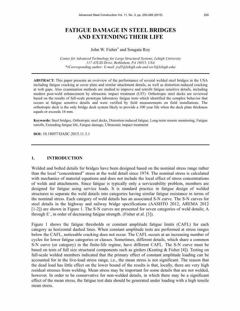
Advanced Steel Construction Vol. 11, No. 3, pp. 250-268 (2015) 250
FATIGUE DAMAGE IN STEEL BRIDGES AND EXTENDING THEIR LIFE
John W. Fisher* and Sougata Roy
Center for Advanced Technology for Large Structural Systems, Lehigh University
117 ATLSS Drive, Bethlehem, PA 18015, USA *(Corresponding author: E-mail: [email protected] and [email protected])
ABSTRACT: This paper presents an overview of the performance of several welded steel bridges in the USA including fatigue cracking at cover plate and similar attachment details, as well as distortion-induced cracking at web gaps. Also examination methods are studied to improve and retrofit fatigue sensitive details, including modern post-weld enhancement by ultrasonic impact treatment (UIT). Orthotropic steel decks are reviewed based on the results of full-scale prototype laboratory fatigue tests which identified the complex behavior that occurs at fatigue sensitive details and were verified by field measurements on field installations. The orthotropic deck is the only bridge deck system likely to provide a 100 year life when the deck plate thickness equals or exceeds 16 mm. Keywords: Steel bridges, Orthotropic steel decks, Distortion-induced fatigue, Long-term remote monitoring, Fatigue retrofit, Extending fatigue life, Fatigue damage, Ultrasonic impact treatment DOI: 10.18057/IJASC.2015.11.3.1
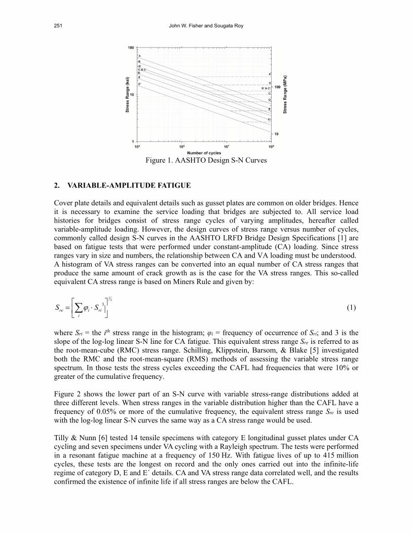
1. INTRODUCTION Welded and bolted details for bridges have been designed based on the nominal stress range rather than the local “concentrated” stress at the weld detail since 1974. The nominal stress is calculated with mechanics of material equations and does not include the local effect of stress concentrations of welds and attachments. Since fatigue is typically only a serviceability problem, members are designed for fatigue using service loads. It is standard practice in fatigue design of welded structures to separate the weld details into categories having similar fatigue resistance in terms of the nominal stress. Each category of weld details has an associated S-N curve. The S-N curves for steel details in the highway and railway bridge specifications (AASHTO 2012, AREMA 2012 [1-2]) are shown in Figure 1. The S-N curves are presented for seven categories of weld details; A through E´, in order of decreasing fatigue strength. (Fisher et al. [3]). Figure 1 shows the fatigue thresholds or constant amplitude fatigue limits (CAFL) for each category as horizontal dashed lines. When constant amplitude tests are performed at stress ranges below the CAFL, noticeable cracking does not occur. The CAFL occurs at an increasing number of cycles for lower fatigue categories or classes. Sometimes, different details, which share a common S-N curve (or category) in the finite-life regime, have different CAFL. The S-N curve must be based on tests of full size structural components such as girders (Keating & Fisher [4]). Testing on full-scale welded members indicated that the primary effect of constant amplitude loading can be accounted for in the live-load stress range, i.e., the mean stress is not significant. The reason that the dead load has little effect on the lower bound of the results is that, locally, there are very high residual stresses from welding. Mean stress may be important for some details that are not welded, however. In order to be conservative for non-welded details, in which there may be a significant effect of the mean stress, the fatigue test data should be generated under loading with a high tensile mean stress.
251 John W. Fisher and Sougata Roy
Figure 1. AASHTO Design S-N Curves
2. VARIABLE-AMPLITUDE FATIGUE Cover plate details and equivalent details such as gusset plates are common on older bridges. Hence it is necessary to examine the service loading that bridges are subjected to. All service load histories for bridges consist of stress range cycles of varying amplitudes, hereafter called variable-amplitude loading. However, the design curves of stress range versus number of cycles, commonly called design S-N curves in the AASHTO LRFD Bridge Design Specifications [1] are based on fatigue tests that were performed under constant-amplitude (CA) loading. Since stress ranges vary in size and numbers, the relationship between CA and VA loading must be understood. A histogram of VA stress ranges can be converted into an equal number of CA stress ranges that produce the same amount of crack growth as is the case for the VA stress ranges. This so-called equivalent CA stress range is based on Miners Rule and given by:
31
3
iriire SS (1)
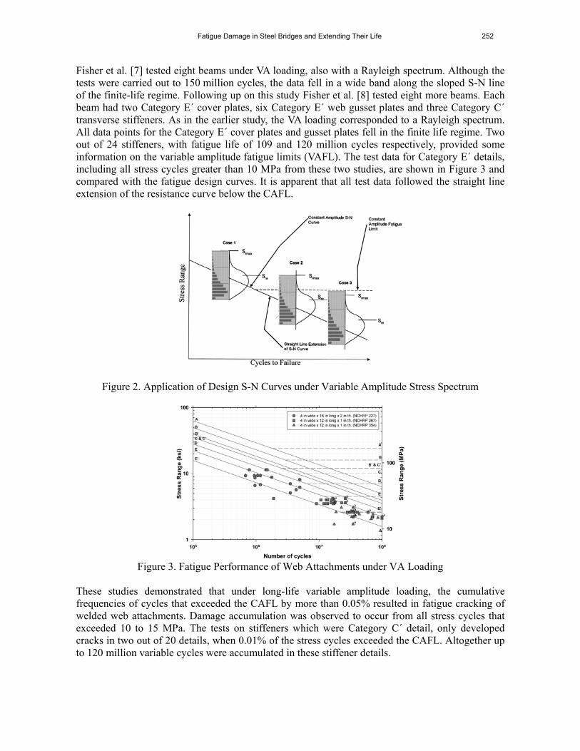
where Sri = the ith stress range in the histogram; φi = frequency of occurrence of Sri; and 3 is the slope of the log-log linear S-N line for CA fatigue. This equivalent stress range Sre is referred to as the root-mean-cube (RMC) stress range. Schilling, Klippstein, Barsom, & Blake [5] investigated both the RMC and the root-mean-square (RMS) methods of assessing the variable stress range spectrum. In those tests the stress cycles exceeding the CAFL had frequencies that were 10% or greater of the cumulative frequency. Figure 2 shows the lower part of an S-N curve with variable stress-range distributions added at three different levels. When stress ranges in the variable distribution higher than the CAFL have a frequency of 0.05% or more of the cumulative frequency, the equivalent stress range Sre is used with the log-log linear S-N curves the same way as a CA stress range would be used. Tilly & Nunn [6] tested 14 tensile specimens with category E longitudinal gusset plates under CA cycling and seven specimens under VA cycling with a Rayleigh spectrum. The tests were performed in a resonant fatigue machine at a frequency of 150 Hz. With fatigue lives of up to 415 million cycles, these tests are the longest on record and the only ones carried out into the infinite-life regime of category D, E and E´ details. CA and VA stress range data correlated well, and the results confirmed the existence of infinite life if all stress ranges are below the CAFL.
Fatigue Damage in Steel Bridges and Extending Their Life 252
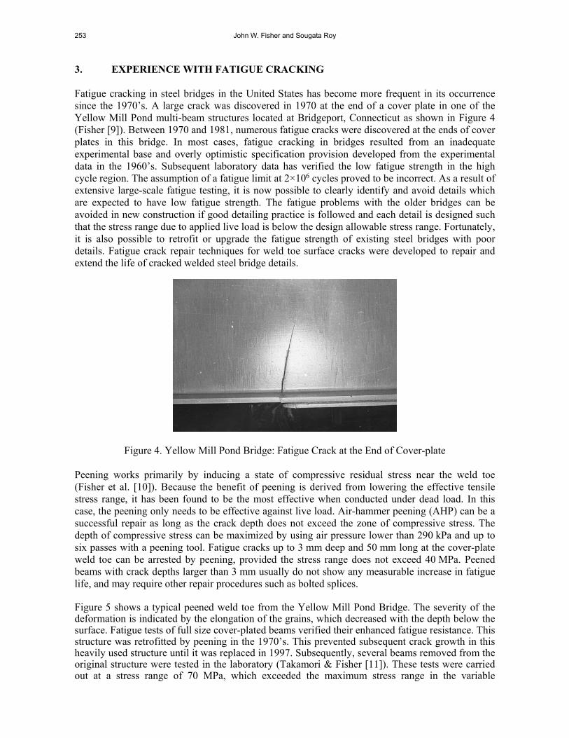
Fisher et al. [7] tested eight beams under VA loading, also with a Rayleigh spectrum. Although the tests were carried out to 150 million cycles, the data fell in a wide band along the sloped S-N line of the finite-life regime. Following up on this study Fisher et al. [8] tested eight more beams. Each beam had two Category E´ cover plates, six Category E´ web gusset plates and three Category C´ transverse stiffeners. As in the earlier study, the VA loading corresponded to a Rayleigh spectrum. All data points for the Category E´ cover plates and gusset plates fell in the finite life regime. Two out of 24 stiffeners, with fatigue life of 109 and 120 million cycles respectively, provided some information on the variable amplitude fatigue limits (VAFL). The test data for Category E´ details, including all stress cycles greater than 10 MPa from these two studies, are shown in Figure 3 and compared with the fatigue design curves. It is apparent that all test data followed the straight line extension of the resistance curve below the CAFL.
Figure 2. Application of Design S-N Curves under Variable Amplitude Stress Spectrum
Figure 3. Fatigue Performance of Web Attachments under VA Loading
These studies demonstrated that under long-life variable amplitude loading, the cumulative frequencies of cycles that exceeded the CAFL by more than 0.05% resulted in fatigue cracking of welded web attachments. Damage accumulation was observed to occur from all stress cycles that exceeded 10 to 15 MPa. The tests on stiffeners which were Category C´ detail, only developed cracks in two out of 20 details, when 0.01% of the stress cycles exceeded the CAFL. Altogether up to 120 million variable cycles were accumulated in these stiffener details.
253 John W. Fisher and Sougata Roy
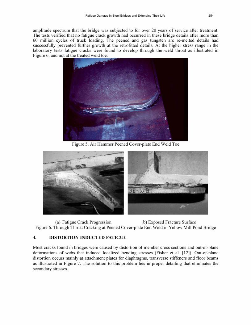
3. EXPERIENCE WITH FATIGUE CRACKING Fatigue cracking in steel bridges in the United States has become more frequent in its occurrence since the 1970’s. A large crack was discovered in 1970 at the end of a cover plate in one of the Yellow Mill Pond multi-beam structures located at Bridgeport, Connecticut as shown in Figure 4 (Fisher [9]). Between 1970 and 1981, numerous fatigue cracks were discovered at the ends of cover plates in this bridge. In most cases, fatigue cracking in bridges resulted from an inadequate experimental base and overly optimistic specification provision developed from the experimental data in the 1960’s. Subsequent laboratory data has verified the low fatigue strength in the high cycle region. The assumption of a fatigue limit at 2×10⁶ cycles proved to be incorrect. As a result of extensive large-scale fatigue testing, it is now possible to clearly identify and avoid details which are expected to have low fatigue strength. The fatigue problems with the older bridges can be avoided in new construction if good detailing practice is followed and each detail is designed such that the stress range due to applied live load is below the design allowable stress range. Fortunately, it is also possible to retrofit or upgrade the fatigue strength of existing steel bridges with poor details. Fatigue crack repair techniques for weld toe surface cracks were developed to repair and extend the life of cracked welded steel bridge details.
Figure 4. Yellow Mill Pond Bridge: Fatigue Crack at the End of Cover-plate Peening works primarily by inducing a state of compressive residual stress near the weld toe (Fisher et al. [10]). Because the benefit of peening is derived from lowering the effective tensile stress range, it has been found to be the most effective when conducted under dead load. In this case, the peening only needs to be effective against live load. Air-hammer peening (AHP) can be a successful repair as long as the crack depth does not exceed the zone of compressive stress. The depth of compressive stress can be maximized by using air pressure lower than 290 kPa and up to six passes with a peening tool. Fatigue cracks up to 3 mm deep and 50 mm long at the cover-plate weld toe can be arrested by peening, provided the stress range does not exceed 40 MPa. Peened beams with crack depths larger than 3 mm usually do not show any measurable increase in fatigue life, and may require other repair procedures such as bolted splices. Figure 5 shows a typical peened weld toe from the Yellow Mill Pond Bridge. The severity of the deformation is indicated by the elongation of the grains, which decreased with the depth below the surface. Fatigue tests of full size cover-plated beams verified their enhanced fatigue resistance. This structure was retrofitted by peening in the 1970’s. This prevented subsequent crack growth in this heavily used structure until it was replaced in 1997. Subsequently, several beams removed from the original structure were tested in the laboratory (Takamori & Fisher [11]). These tests were carried out at a stress range of 70 MPa, which exceeded the maximum stress range in the variable
Fatigue Damage in Steel Bridges and Extending Their Life 254
amplitude spectrum that the bridge was subjected to for over 20 years of service after treatment. The tests verified that no fatigue crack growth had occurred in these bridge details after more than 60 million cycles of truck loading. The peened and gas tungsten arc re-melted details had successfully prevented further growth at the retrofitted details. At the higher stress range in the laboratory tests fatigue cracks were found to develop through the weld throat as illustrated in Figure 6, and not at the treated weld toe.
Figure 5. Air Hammer Peened Cover-plate End Weld Toe
(a) Fatigue Crack Progression (b) Exposed Fracture Surface
Figure 6. Through Throat Cracking at Peened Cover-plate End Weld in Yellow Mill Pond Bridge 4. DISTORTION-INDUCTED FATIGUE
Most cracks found in bridges were caused by distortion of member cross sections and out-of-plane deformations of webs that induced localized bending stresses (Fisher et al. [12]). Out-of-plane distortion occurs mainly at attachment plates for diaphragms, transverse stiffeners and floor beams as illustrated in Figure 7. The solution to this problem lies in proper detailing that eliminates the secondary stresses.
255 John W. Fisher and Sougata Roy
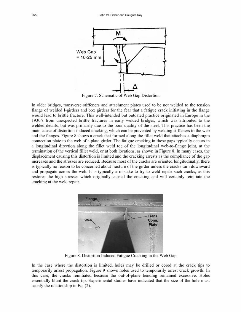
Figure 7. Schematic of Web Gap Distortion
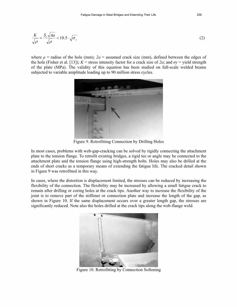
In older bridges, transverse stiffeners and attachment plates used to be not welded to the tension flange of welded I-girders and box girders for the fear that a fatigue crack initiating in the flange would lead to brittle fracture. This well-intended but outdated practice originated in Europe in the 1930’s from unexpected brittle fractures in early welded bridges, which was attributed to the welded details, but was primarily due to the poor quality of the steel. This practice has been the main cause of distortion-induced cracking, which can be prevented by welding stiffeners to the web and the flanges. Figure 8 shows a crack that formed along the fillet weld that attaches a diaphragm connection plate to the web of a plate girder. The fatigue cracking in these gaps typically occurs in a longitudinal direction along the fillet weld toe of the longitudinal web-to-flange joint, at the termination of the vertical fillet weld, or at both locations, as shown in Figure 8. In many cases, the displacement causing this distortion is limited and the cracking arrests as the compliance of the gap increases and the stresses are reduced. Because most of the cracks are oriented longitudinally, there is typically no reason to be concerned about fracture of the girder unless the cracks turn downward and propagate across the web. It is typically a mistake to try to weld repair such cracks, as this restores the high stresses which originally caused the cracking and will certainly reinitiate the cracking at the weld repair.
Figure 8. Distortion Induced Fatigue Cracking in the Web Gap
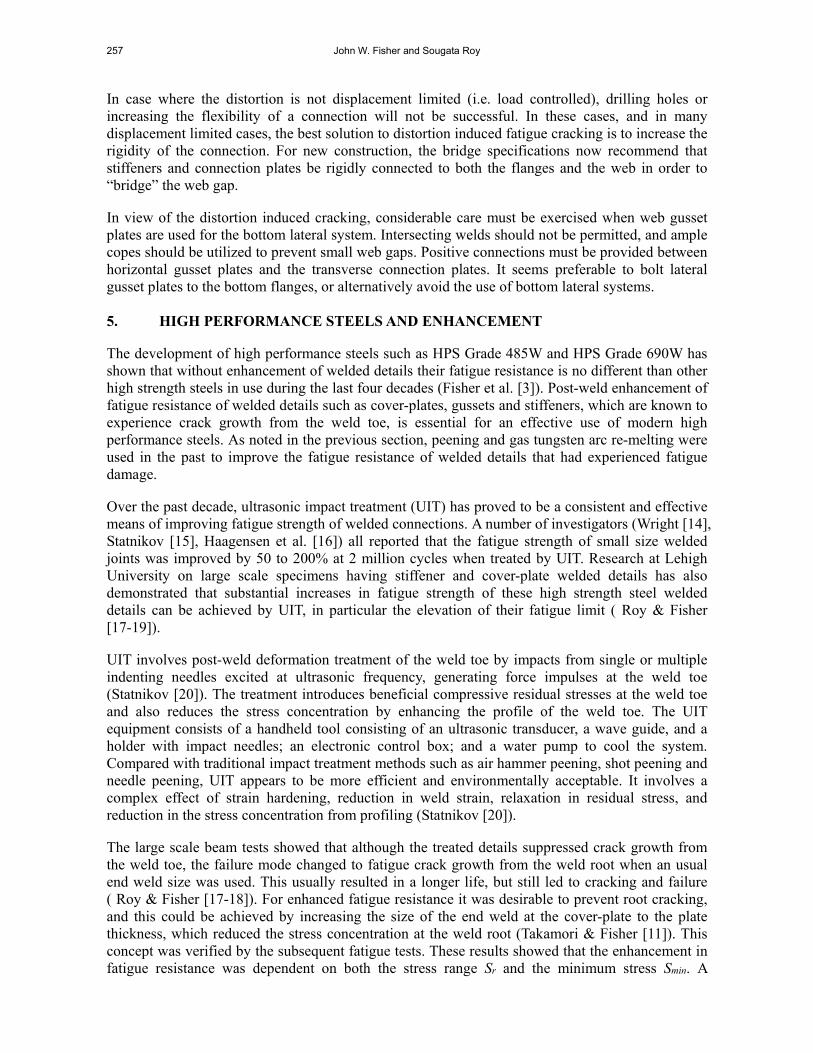
In the case where the distortion is limited, holes may be drilled or cored at the crack tips to temporarily arrest propagation. Figure 9 shows holes used to temporarily arrest crack growth. In this case, the cracks reinitiated because the out-of-plane bending remained excessive. Holes essentially blunt the crack tip. Experimental studies have indicated that the size of the hole must satisfy the relationship in Eq. (2).
Fatigue Damage in Steel Bridges and Extending Their Life 256
yr aSK
5.10 (2)
where ρ = radius of the hole (mm); 2a = assumed crack size (mm), defined between the edges of the hole (Fisher et al. [13]); K = stress intensity factor for a crack size of 2a; and σy = yield strength of the plate (MPa). The validity of this equation has been studied on full-scale welded beams subjected to variable amplitude loading up to 90 million stress cycles.
Figure 9. Retrofitting Connection by Drilling Holes
In most cases, problems with web-gap-cracking can be solved by rigidly connecting the attachment plate to the tension flange. To retrofit existing bridges, a rigid tee or angle may be connected to the attachment plate and the tension flange using high-strength bolts. Holes may also be drilled at the ends of short cracks as a temporary means of extending the fatigue life. The cracked detail shown in Figure 9 was retrofitted in this way.
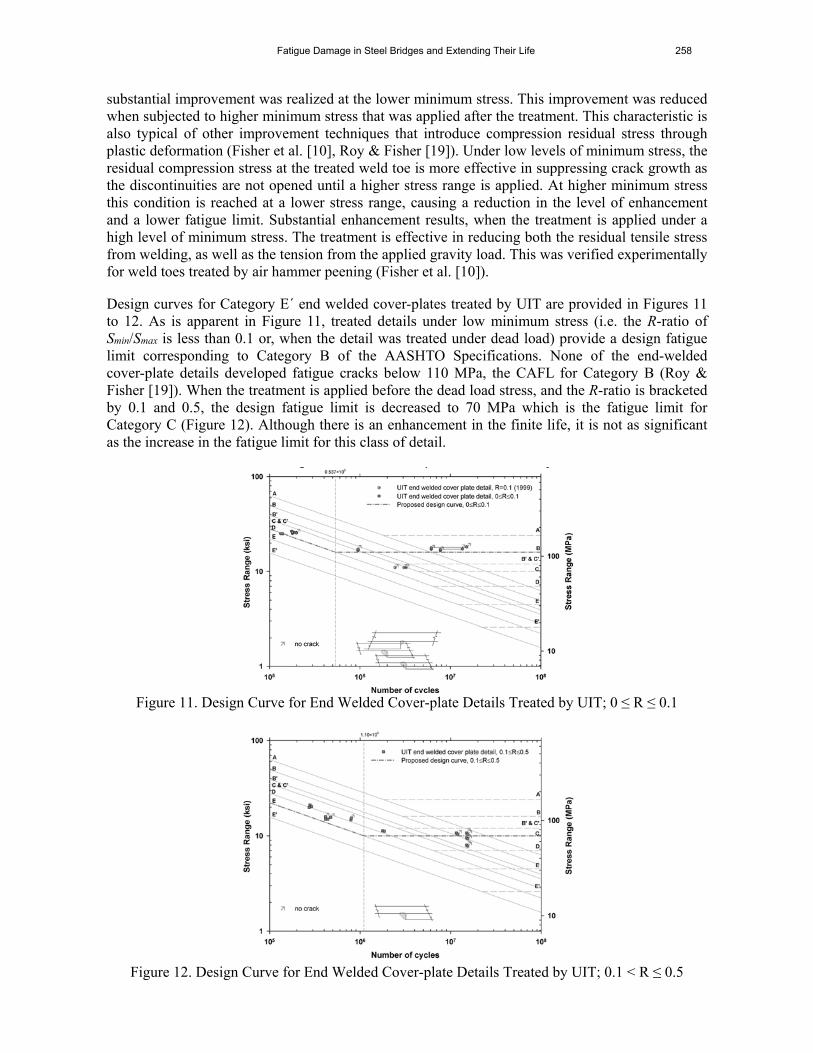
In cases, where the distortion is displacement limited, the stresses can be reduced by increasing the flexibility of the connection. The flexibility may be increased by allowing a small fatigue crack to remain after drilling or coring holes at the crack tips. Another way to increase the flexibility of the joint is to remove part of the stiffener or connection plate and increase the length of the gap, as shown in Figure 10. If the same displacement occurs over a greater length gap, the stresses are significantly reduced. Note also the holes drilled at the crack tips along the web-flange weld.
Figure 10. Retrofitting by Connection Softening
257 John W. Fisher and Sougata Roy
In case where the distortion is not displacement limited (i.e. load controlled), drilling holes or increasing the flexibility of a connection will not be successful. In these cases, and in many displacement limited cases, the best solution to distortion induced fatigue cracking is to increase the rigidity of the connection. For new construction, the bridge specifications now recommend that stiffeners and connection plates be rigidly connected to both the flanges and the web in order to “bridge” the web gap.
In view of the distortion induced cracking, considerable care must be exercised when web gusset plates are used for the bottom lateral system. Intersecting welds should not be permitted, and ample copes should be utilized to prevent small web gaps. Positive connections must be provided between horizontal gusset plates and the transverse connection plates. It seems preferable to bolt lateral gusset plates to the bottom flanges, or alternatively avoid the use of bottom lateral systems. 5. HIGH PERFORMANCE STEELS AND ENHANCEMENT
The development of high performance steels such as HPS Grade 485W and HPS Grade 690W has shown that without enhancement of welded details their fatigue resistance is no different than other high strength steels in use during the last four decades (Fisher et al. [3]). Post-weld enhancement of fatigue resistance of welded details such as cover-plates, gussets and stiffeners, which are known to experience crack growth from the weld toe, is essential for an effective use of modern high performance steels. As noted in the previous section, peening and gas tungsten arc re-melting were used in the past to improve the fatigue resistance of welded details that had experienced fatigue damage.
Over the past decade, ultrasonic impact treatment (UIT) has proved to be a consistent and effective means of improving fatigue strength of welded connections. A number of investigators (Wright [14], Statnikov [15], Haagensen et al. [16]) all reported that the fatigue strength of small size welded joints was improved by 50 to 200% at 2 million cycles when treated by UIT. Research at Lehigh University on large scale specimens having stiffener and cover-plate welded details has also demonstrated that substantial increases in fatigue strength of these high strength steel welded details can be achieved by UIT, in particular the elevation of their fatigue limit ( Roy & Fisher [17-19]).
UIT involves post-weld deformation treatment of the weld toe by impacts from single or multiple indenting needles excited at ultrasonic frequency, generating force impulses at the weld toe (Statnikov [20]). The treatment introduces beneficial compressive residual stresses at the weld toe and also reduces the stress concentration by enhancing the profile of the weld toe. The UIT equipment consists of a handheld tool consisting of an ultrasonic transducer, a wave guide, and a holder with impact needles; an electronic control box; and a water pump to cool the system. Compared with traditional impact treatment methods such as air hammer peening, shot peening and needle peening, UIT appears to be more efficient and environmentally acceptable. It involves a complex effect of strain hardening, reduction in weld strain, relaxation in residual stress, and reduction in the stress concentration from profiling (Statnikov [20]).
The large scale beam tests showed that although the treated details suppressed crack growth from the weld toe, the failure mode changed to fatigue crack growth from the weld root when an usual end weld size was used. This usually resulted in a longer life, but still led to cracking and failure ( Roy & Fisher [17-18]). For enhanced fatigue resistance it was desirable to prevent root cracking, and this could be achieved by increasing the size of the end weld at the cover-plate to the plate thickness, which reduced the stress concentration at the weld root (Takamori & Fisher [11]). This concept was verified by the subsequent fatigue tests. These results showed that the enhancement in fatigue resistance was dependent on both the stress range Sr and the minimum stress Smin. A
Fatigue Damage in Steel Bridges and Extending Their Life 258
substantial improvement was realized at the lower minimum stress. This improvement was reduced when subjected to higher minimum stress that was applied after the treatment. This characteristic is also typical of other improvement techniques that introduce compression residual stress through plastic deformation (Fisher et al. [10], Roy & Fisher [19]). Under low levels of minimum stress, the residual compression stress at the treated weld toe is more effective in suppressing crack growth as the discontinuities are not opened until a higher stress range is applied. At higher minimum stress this condition is reached at a lower stress range, causing a reduction in the level of enhancement and a lower fatigue limit. Substantial enhancement results, when the treatment is applied under a high level of minimum stress. The treatment is effective in reducing both the residual tensile stress from welding, as well as the tension from the applied gravity load. This was verified experimentally for weld toes treated by air hammer peening (Fisher et al. [10]).
Design curves for Category E´ end welded cover-plates treated by UIT are provided in Figures 11 to 12. As is apparent in Figure 11, treated details under low minimum stress (i.e. the R-ratio of Smin/Smax is less than 0.1 or, when the detail was treated under dead load) provide a design fatigue limit corresponding to Category B of the AASHTO Specifications. None of the end-welded cover-plate details developed fatigue cracks below 110 MPa, the CAFL for Category B (Roy & Fisher [19]). When the treatment is applied before the dead load stress, and the R-ratio is bracketed by 0.1 and 0.5, the design fatigue limit is decreased to 70 MPa which is the fatigue limit for Category C (Figure 12). Although there is an enhancement in the finite life, it is not as significant as the increase in the fatigue limit for this class of detail.
Figure 11. Design Curve for End Welded Cover-plate Details Treated by UIT; 0 ≤ R ≤ 0.1
Figure 12. Design Curve for End Welded Cover-plate Details Treated by UIT; 0.1 < R ≤ 0.5
259 John W. Fisher and Sougata Roy
Cover-plate end welds on existing bridges are more likely to be about half the plate thickness. The test results indicated that when the R-ratio was less than 0.1, the enhanced fatigue resistance was applicable to these weld toes. There is a high probability that fatigue crack growth will initiate at the weld root, as was demonstrated in the test girders removed from the Yellow Mill Pond bridge that were treated by air hammer peening and gas tungsten arc re-melting (Takamori & Fisher [11]). This would suggest that inspections should focus on the weld throat to monitor subsequent root cracking. Fortunately, there is a significant increase in life for root cracking to occur and the cycles (time) necessary for the crack to propagate across the cover-plate end to the longitudinal welds, which is the only way the crack can enter into the girder flange. Usual intervals of inspection should identify such throat cracking if it ever occurs. 6. ORTHOTROPIC STEEL DECKS
During the past decade, full-scale laboratory and field testing of portions of several orthotropic bridge decks were conducted (Tsakopoulos & Fisher [21-22], Roy & Fisher [23-24]). These tests were carried out to minimize the possibility of fatigue cracking, as orthotropic deck systems in service in Europe, Australia and Japan have exhibited fatigue cracking in various components of the steel deck system. These included: cracking at rib-to-floor beam (or diaphragm) connections in the rib-wall and in the diaphragm web; and cracking in the deck plate at the rib-to-deck plate, and at the diaphragm-to-deck plate connections, particularly when the deck plate thickness was less than 14 mm, and when fillet welds were used to connect the ribs to the deck plate (Cuninghame & Beales [25], Miki et al. [26], Jong [27], Machida et al. [28], Miki [29]).
Particularly sensitive in the orthotropic deck system is the rib-to-diaphragm connection – the welded connection between the transverse (floor beam) diaphragm plate and the continuous longitudinal ribs that are being supported. This connection is subjected to a variable combination of localized in-plane and out-of-plane bending stresses that are complex (Gajer et al. [30]) and make it susceptible to load-induced fatigue cracking.
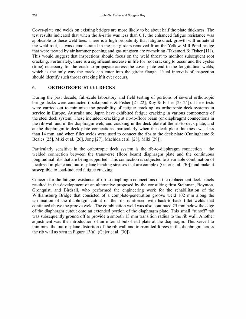
Concern for the fatigue resistance of rib-to-diaphragm connections on the replacement deck panels resulted in the development of an alternative proposed by the consulting firm Steinman, Boynton, Gronquist, and Birdsall, who performed the engineering work for the rehabilitation of the Williamsburg Bridge that consisted of a complete-penetration groove weld 102 mm along the termination of the diaphragm cutout on the rib, reinforced with back-to-back fillet welds that continued above the groove weld. The combination weld was also continued 25 mm below the edge of the diaphragm cutout onto an extended portion of the diaphragm plate. This small “runoff” tab was subsequently ground off to provide a smooth 13 mm transition radius to the rib wall. Another adjustment was the introduction of an internal bulk-head plate at the diaphragm. This served to minimize the out-of-plane distortion of the rib wall and transmitted forces in the diaphragm across the rib wall as seen in Figure 13(a). (Gajer et al. [30]).
Fatigue Damage in Steel Bridges and Extending Their Life 260
(a) Williamsburg Bridge (b) Bronx-Whitestone Bridge
Figure 13. Cross Sections and Schema of Stress Field at Rib to Floor Beam Connection in as-built Orthotropic Decks
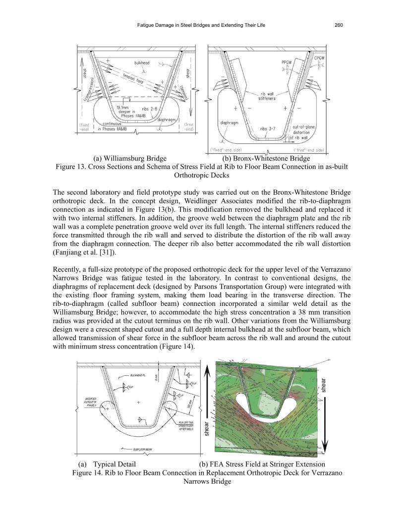
The second laboratory and field prototype study was carried out on the Bronx-Whitestone Bridge orthotropic deck. In the concept design, Weidlinger Associates modified the rib-to-diaphragm connection as indicated in Figure 13(b). This modification removed the bulkhead and replaced it with two internal stiffeners. In addition, the groove weld between the diaphragm plate and the rib wall was a complete penetration groove weld over its full length. The internal stiffeners reduced the force transmitted through the rib wall and served to distribute the distortion of the rib wall away from the diaphragm connection. The deeper rib also better accommodated the rib wall distortion (Fanjiang et al. [31]). Recently, a full-size prototype of the proposed orthotropic deck for the upper level of the Verrazano Narrows Bridge was fatigue tested in the laboratory. In contrast to conventional designs, the diaphragms of replacement deck (designed by Parsons Transportation Group) were integrated with the existing floor framing system, making them load bearing in the transverse direction. The rib-to-diaphragm (called subfloor beam) connection incorporated a similar weld detail as the Williamsburg Bridge; however, to accommodate the high stress concentration a 38 mm transition radius was provided at the cutout terminus on the rib wall. Other variations from the Williamsburg design were a crescent shaped cutout and a full depth internal bulkhead at the subfloor beam, which allowed transmission of shear force in the subfloor beam across the rib wall and around the cutout with minimum stress concentration (Figure 14).
(a) Typical Detail (b) FEA Stress Field at Stringer Extension
Figure 14. Rib to Floor Beam Connection in Replacement Orthotropic Deck for Verrazano Narrows Bridge
261 John W. Fisher and Sougata Roy
6.1 Prototype Laboratory Tests The Williamsburg Bridge test program was carried out between 1995 and 1998 on a prototype and on an as-built deck panel (Tsakopoulos & Fisher [21]). The second test program was carried out between 2001 and 2002 on the prototype deck panel for the Bronx-Whitestone Bridge (Tsakopoulos & Fisher [22]). The testing of the prototype deck for the Verrazano Narrows Bridge (Roy & Fisher [23-24]) was carried out between 2009 and 2011. These independent laboratory fatigue tests on full-size deck panels were conducted in the multidirectional testing facility at the Advanced Technology for Large Structural Systems (ATLSS) Engineering Research Center of Lehigh University. The replacement orthotropic deck panels were designed to be incorporated onto the suspended portion of the Williamsburg and Bronx-Whitestone Bridge superstructures that consist of a deep longitudinal truss and girder system respectively, and transverse floorbeams located at about 6 m intervals for supporting the roadway decking. The orthotropic deck panels for the Verrazano Narrows Bridge were designed to replace the existing concrete-filled grid deck at the upper level of the suspended structure that consisted of a vertical stiffening truss at each fascia and a transverse twin-cell box at each node of the stiffening truss serving as floor beams to the upper and lower decks. The replacement deck was supported by and integrated with the floor framing that also included eight longitudinal stringers spanning between the floor beams. The deck panels were fabricated from structural elements, which included a steel plate deck surface, longitudinal ribs, transverse floorbeam diaphragms or subfloor beams, intermediate diaphragms or subfloor beams, and bracket stiffener plates or stringer extension plates that were welded to the underside of deck plate. The ribs were supported by the floorbeam diaphragms or subfloor beams at the cutouts, and transferred loads from the deck plate to the superstructure. Intermediate diaphragms or the subfloor beams provided additional global torsional stiffness to the deck system by transferring shear and controlling local relative displacement of the deck plate between ribs. For the Verrazano Narrows Bridge deck, where the intermediate subfloor beams were made integral with the stringer extensions, they also transferred load from the deck plate to the floor framing by shear. Figure 15 and 16 show the cross-section of the bridge superstructures upon completion of the rehabilitation, and the full-scale setups of the roadway sections that were simulated in the laboratory. During the design process of the bridge decks, it was recognized that the welded connection between the transverse floorbeam diaphragm plate or the subfloor beam web and the continuous longitudinal ribs (rib-to-diaphragm or rib-to-subfloor beam) was sensitive to fatigue cracking. Several orthotropic decks in service were known to have developed load-induced fatigue cracks as a result of localized in-plane and out-of-plane bending stresses that are complex and variable at this location (Gajer et al. [30], Fanjiang et al. [31]). No wearing surface was applied to the 16 mm deck plates, as it was left exposed for the installation of strain gages and inspection of possible fatigue cracking in both test programs. The loading configuration for the Williamsburg Bridge and the Bronx-Whitestone Bridge decks represented a single-axle that was consistent with the characteristics of a HS20 design truck axle and the HS15 fatigue truck. This provided a more severe loading condition on the floorbeam diaphragm(s) than if a tandem-axle was used. For the Verrazano Narrows Bridge deck testing, however, the single axle load was split into a tandem configuration consistent with the AASHTO HL-93 loading and the FHWA Manual for Orthotropic Decks (Connor et al. [32]).
Fatigue Damage in Steel Bridges and Extending Their Life 262
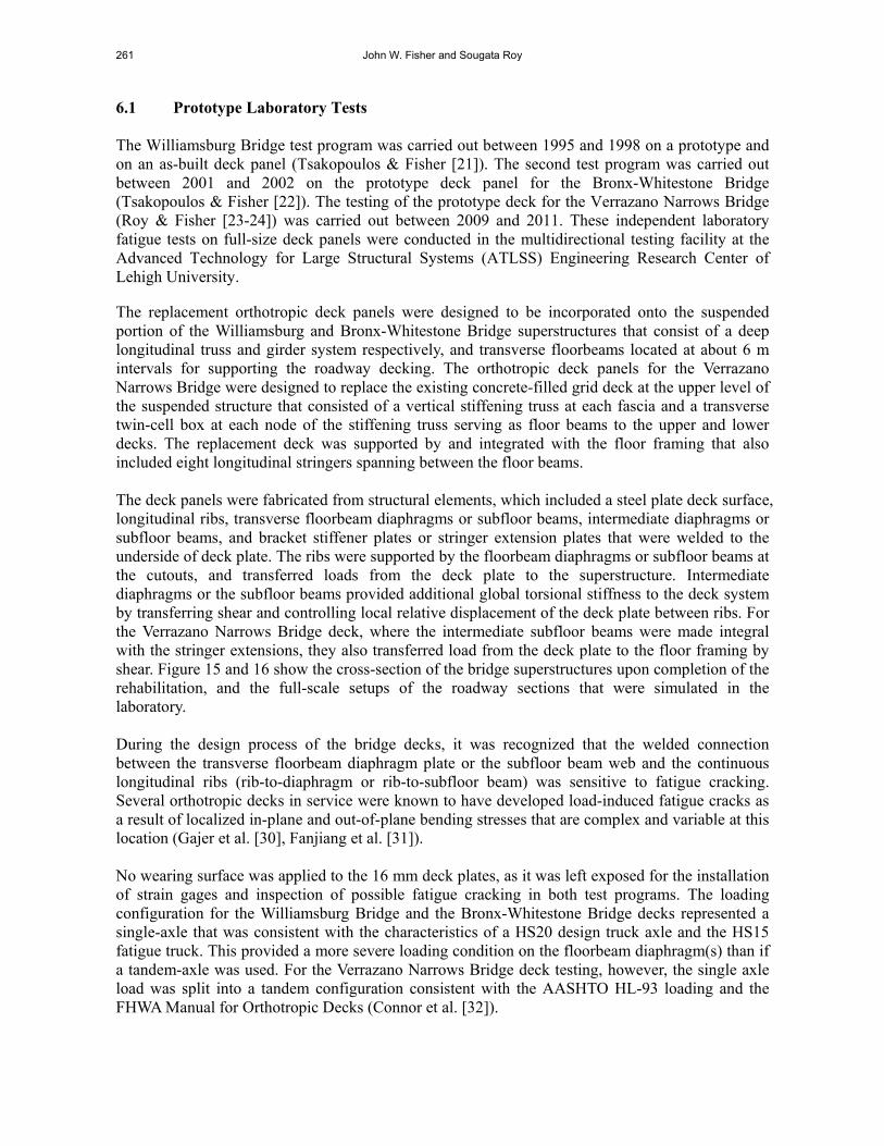
(a) Williamsburg Bridge (as-built Floorbeam Diaphragm)
(b) Bronx Whites Tone Bridge (Prototype Floorbeam Diaphragm)
Figure 15. Cross-section of Full-scale Setup in Laboratory The test program on the Williamsburg Bridge prototype is described in detail in (Tsakopoulos & Fisher [21]). The axle loads were applied by three to five deck actuators spaced at 3.1 m along the test deck. The dynamic tests had axle loads that varied from (1.33 to 3.07 HS15) 142 kN to 327 kN during the different phases of the test program.
263 John W. Fisher and Sougata Roy
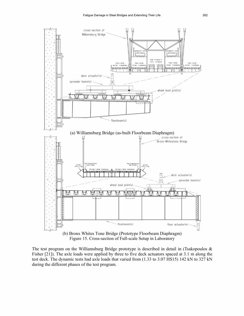
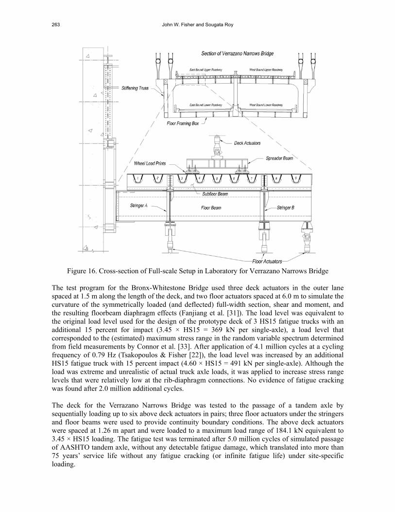
Figure 16. Cross-section of Full-scale Setup in Laboratory for Verrazano Narrows Bridge
The test program for the Bronx-Whitestone Bridge used three deck actuators in the outer lane spaced at 1.5 m along the length of the deck, and two floor actuators spaced at 6.0 m to simulate the curvature of the symmetrically loaded (and deflected) full-width section, shear and moment, and the resulting floorbeam diaphragm effects (Fanjiang et al. [31]). The load level was equivalent to the original load level used for the design of the prototype deck of 3 HS15 fatigue trucks with an additional 15 percent for impact (3.45 × HS15 = 369 kN per single-axle), a load level that corresponded to the (estimated) maximum stress range in the random variable spectrum determined from field measurements by Connor et al. [33]. After application of 4.1 million cycles at a cycling frequency of 0.79 Hz (Tsakopoulos & Fisher [22]), the load level was increased by an additional HS15 fatigue truck with 15 percent impact (4.60 × HS15 = 491 kN per single-axle). Although the load was extreme and unrealistic of actual truck axle loads, it was applied to increase stress range levels that were relatively low at the rib-diaphragm connections. No evidence of fatigue cracking was found after 2.0 million additional cycles. The deck for the Verrazano Narrows Bridge was tested to the passage of a tandem axle by sequentially loading up to six above deck actuators in pairs; three floor actuators under the stringers and floor beams were used to provide continuity boundary conditions. The above deck actuators were spaced at 1.26 m apart and were loaded to a maximum load range of 184.1 kN equivalent to 3.45 × HS15 loading. The fatigue test was terminated after 5.0 million cycles of simulated passage of AASHTO tandem axle, without any detectable fatigue damage, which translated into more than 75 years’ service life without any fatigue cracking (or infinite fatigue life) under site-specific loading.
Fatigue Damage in Steel Bridges and Extending Their Life 264
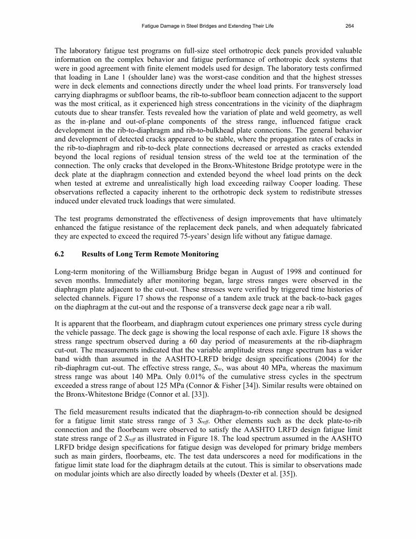
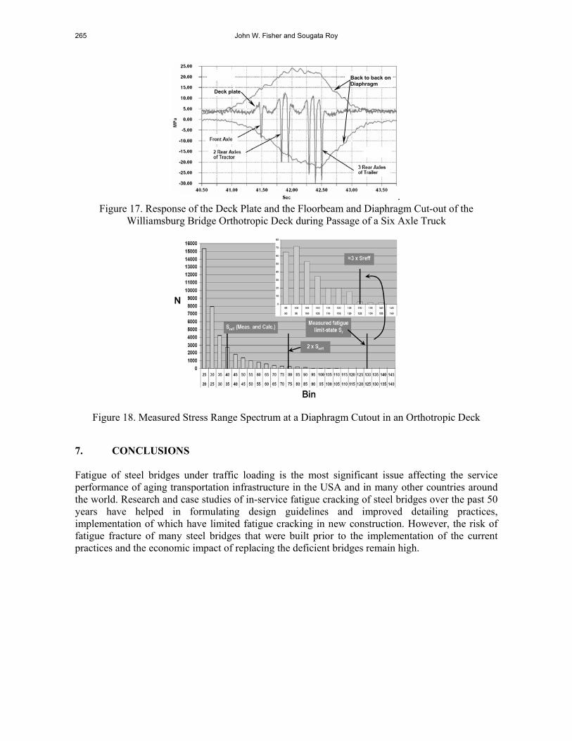
The laboratory fatigue test programs on full-size steel orthotropic deck panels provided valuable information on the complex behavior and fatigue performance of orthotropic deck systems that were in good agreement with finite element models used for design. The laboratory tests confirmed that loading in Lane 1 (shoulder lane) was the worst-case condition and that the highest stresses were in deck elements and connections directly under the wheel load prints. For transversely load carrying diaphragms or subfloor beams, the rib-to-subfloor beam connection adjacent to the support was the most critical, as it experienced high stress concentrations in the vicinity of the diaphragm cutouts due to shear transfer. Tests revealed how the variation of plate and weld geometry, as well as the in-plane and out-of-plane components of the stress range, influenced fatigue crack development in the rib-to-diaphragm and rib-to-bulkhead plate connections. The general behavior and development of detected cracks appeared to be stable, where the propagation rates of cracks in the rib-to-diaphragm and rib-to-deck plate connections decreased or arrested as cracks extended beyond the local regions of residual tension stress of the weld toe at the termination of the connection. The only cracks that developed in the Bronx-Whitestone Bridge prototype were in the deck plate at the diaphragm connection and extended beyond the wheel load prints on the deck when tested at extreme and unrealistically high load exceeding railway Cooper loading. These observations reflected a capacity inherent to the orthotropic deck system to redistribute stresses induced under elevated truck loadings that were simulated. The test programs demonstrated the effectiveness of design improvements that have ultimately enhanced the fatigue resistance of the replacement deck panels, and when adequately fabricated they are expected to exceed the required 75-years’ design life without any fatigue damage. 6.2 Results of Long Term Remote Monitoring Long-term monitoring of the Williamsburg Bridge began in August of 1998 and continued for seven months. Immediately after monitoring began, large stress ranges were observed in the diaphragm plate adjacent to the cut-out. These stresses were verified by triggered time histories of selected channels. Figure 17 shows the response of a tandem axle truck at the back-to-back gages on the diaphragm at the cut-out and the response of a transverse deck gage near a rib wall. It is apparent that the floorbeam, and diaphragm cutout experiences one primary stress cycle during the vehicle passage. The deck gage is showing the local response of each axle. Figure 18 shows the stress range spectrum observed during a 60 day period of measurements at the rib-diaphragm cut-out. The measurements indicated that the variable amplitude stress range spectrum has a wider band width than assumed in the AASHTO-LRFD bridge design specifications (2004) for the rib-diaphragm cut-out. The effective stress range, Sre, was about 40 MPa, whereas the maximum stress range was about 140 MPa. Only 0.01% of the cumulative stress cycles in the spectrum exceeded a stress range of about 125 MPa (Connor & Fisher [34]). Similar results were obtained on the Bronx-Whitestone Bridge (Connor et al. [33]). The field measurement results indicated that the diaphragm-to-rib connection should be designed for a fatigue limit state stress range of 3 Sreff. Other elements such as the deck plate-to-rib connection and the floorbeam were observed to satisfy the AASHTO LRFD design fatigue limit state stress range of 2 Sreff as illustrated in Figure 18. The load spectrum assumed in the AASHTO LRFD bridge design specifications for fatigue design was developed for primary bridge members such as main girders, floorbeams, etc. The test data underscores a need for modifications in the fatigue limit state load for the diaphragm details at the cutout. This is similar to observations made on modular joints which are also directly loaded by wheels (Dexter et al. [35]).
265 John W. Fisher and Sougata Roy
. Figure 17. Response of the Deck Plate and the Floorbeam and Diaphragm Cut-out of the
Williamsburg Bridge Orthotropic Deck during Passage of a Six Axle Truck
Figure 18. Measured Stress Range Spectrum at a Diaphragm Cutout in an Orthotropic Deck 7. CONCLUSIONS Fatigue of steel bridges under traffic loading is the most significant issue affecting the service performance of aging transportation infrastructure in the USA and in many other countries around the world. Research and case studies of in-service fatigue cracking of steel bridges over the past 50 years have helped in formulating design guidelines and improved detailing practices, implementation of which have limited fatigue cracking in new construction. However, the risk of fatigue fracture of many steel bridges that were built prior to the implementation of the current practices and the economic impact of replacing the deficient bridges remain high.
Back to back on Diaphragm
Deck plate
Fatigue Damage in Steel Bridges and Extending Their Life 266
Historically most of the fatigue cracking of the welded steel bridges in the USA occurred at cover plate and similar attachment details, as well as at the web gaps from distortion. The attachment details are the most severe of the fatigue critical details, which are characterized by crack growth at the weld toe. While fatigue fracture limit state in new steel bridges can be suppressed by avoiding the fatigue critical Category D, E or E´ attachments, the performance of these details in existing bridges may be enhanced by weld toe treatments such as air hammer peening, GTA re-melting, or UIT. Post-weld toe treatments should also be considered in new structures for efficient use of modern HPS, where the attachment details including Category C´ connection plates and stiffeners cannot be avoided. Distortion induced fatigue cracking in the web gaps may be solved by proper detailing that eliminates the secondary stresses driving these cracks. In most cases, the web-gap-cracking can be prevented by rigidly connecting the attachment plates to the tension flange. Where the distortion is displacement controlled, the stresses can be reduced by increasing the flexibility of the connection. If distortion is limited, holes may be drilled or cored at the crack tips to temporarily arrest propagation. When the cumulative stress ranges in the variable stress spectrum exceeds the CAFL by 0.05% or more of the total stress cycles in the distribution, the fatigue resistance of the attachments is given by the extension of the linear sloped part of the S-N curve below the CAFL. An infinite life may be assumed when the cumulative exceedence of the stress cycles beyond the CAFL is limited to 0.01% of the total. Most structures carry enough truck traffic to justify designing them for an infinite fatigue life, especially the deck elements. The orthotropic deck is the only bridge deck system likely to provide a 100 year life when the deck plate thickness equals or exceeds 16 mm. Particularly sensitive in this deck system is the rib-to-diaphragm connection, which is subjected to a complex combination of local in-plane and out-of-plane bending stresses rendering it susceptible to load-induced fatigue cracking. Field measurements indicate that the diaphragm-to-rib connection should be designed for a fatigue limit state stress range of three times the effective stress range of the live load stress spectrum. A minimum deck plate thickness is necessary to reduce local stress in the overlay and improve its durability by limiting fatigue cracking. REFERENCES [1] AASHTO 2012, “LRFD Bridge Design Specifications”, Washington, D.C.: American
Association of State Highway and Transportation Officials (AASHTO). [2] AREMA 2012. Manual of railway engineering. Washington, D.C.: American Railway
Engineering and Maintenance of Way Association (AREMA). [3] Fisher, J.W., Frank, K.H., Hirt, M.A. and McNamee, B.M., “Effect of Weldments on the
Fatigue Strength of Steel Beams”, NCHRP Report 102, Washington, D.C.: Highway Research Board, 1970.
[4] Keating, P. and Fisher, J.W., “Evaluation of Fatigue Tests and Design Criteria on Welded Details”, NCHRP Report 286. Washington, D.C.: Transportation Research Board, 1986.
[5] Schilling, C.G., Klippstein, K.H., Barsom, J.M. and Blake, G.T., “Fatigue of Welded Steel Bridge Members under Variable Ampltude Loading”, NCHRP Report 188, Washington, D.C.: Transportation Research Board, 1978.
[6] Tilly, G.P. and Nunn, D.E., “Variable Amplitude Fatigue in Relation to Highway Bridges”, Proceedings of the Institution of Mechanical Engineers (London), 1980, Vol. 194, pp. 259-267.
267 John W. Fisher and Sougata Roy
[7] Fisher, J.W., Mertz, D.R. and Zhong, A., “Steel Bridge Members under Variable Amplitude Long Life Fatigue Loading”, NCHRP Report 267. Washington, D.C.: Transportation Research Board, 1983.
[8] Fisher, J.W., Nussbaumer, A., Keating, P.B. and Yen, B.T., “Resistance of Welded Details under Variable Amplitude Long-life Fatigue Loading”, NCHRP Report 354, Washington, D.C.: Transportation Research Board, 1993.
[9] Fisher, J.W., “Fatigue and Fracture in Steel Bridges: Case Studies”, John Wiley, 1984. [10] Fisher, J.W., Hausammann, H., Sullivan, M.D. and Pense, A.W., “Detection and Repair of
Fatigue Damage in Welded Highway Bridges”, NCHRP Report 206. Washington, D.C.: Transportation Research Board, 1979.
[11] Takamori, H. and Fisher, J.W., “Tests of Large girders Treated to Enhance Fatigue Strength”, Transportation Research Record, 2000, Vol. 1696, pp. 93-99.
[12] Fisher, J.W., Jin, J., Wagner, D.C. and Yen, B.T., “Distortion-induced Fatigue Cracking in Steel Bridges”, NCHRP Report 336. Washington, D.C.: Transportation Research Board, 1990.
[13] Fisher, J.W., Barthelemy, B.M., Mertz, D.R. and Edinger, J.A., “Fatigue Behavior of Full-scale Welded Bridge Attachments”, NCHRP Report 227. Washington, D.C.: Transportation Research Board, 1980.
[14] Wright, W.J., “Post-weld Treatment of a Welded Bridge Girder by Ultrasonic Hammer Peening”, FHWA Internal Research Report. McLean, VA: Federal Highway Administration, Turner Fairbank Highway Research Center, 1996.
[15] Statnikov, E.S., “Comparison of Post-weld Deformation Methods for Increase in Fatigue Strength of Welded Joints”, IIW Doc. No. XII-1668-97, Paris: International Institute of Welding, 1997.
[16] Haagensen, P.J., Statnikov, E.S. and Lopez-Martinez, L., “Introductory Fatigue Tests on Welded Joint in High Strength Steel and Aluminum Improved by Various Methods including Ultrasonic Impact Treatment (UIT) ”, IIW Doc. No. XIII-1748-98, Paris: International Institute of Welding, 1998.
[17] Roy, S., Fisher, J.W. and Yen, B.T., “Fatigue Resistance of Welded Details Enhanced by Ultrasonic Impact Treatment (UIT) ”, International Journal of Fatigue, 2003, Vol. 25, No. 9-11, pp. 1239-1247.
[18] Roy, S. and Fisher, J.W., “Enhancing Fatigue Strength by Ultrasonic Impact Treatment”, International Journal of Steel Structures, 2005, Vol. 5, No. 3, pp. 241-252.
[19] Roy, S. and Fisher, J.W., “Modified AASHTO Design S-N Curves for Post-weld Treated Welded Details”, Journal of Bridge Structures - Assessment, Design and Construction, 2006, Vol. 2, No. 4, pp. 207-222.
[20] Statnikov, E.S., “Applications of Operational Ultrasonic Impact Treatment (UIT) Technologies in Production of Welded Joint”, IIW Doc. No. XII-1667-97. Paris: International Institute of Welding, 1997.
[21] Tsakopoulos, P.A. and Fisher, J.W., “Full-scale Fatigue Tests of Steel Orthotropic Decks for the Williamsburg Bridge”, Journal of Bridge Engineering, 2003, Vol. 8, No. 5, pp. 323-333.
[22] Tsakopoulos, P.A. and Fisher, J.W., “Full-scale Fatigue Tests of Orthotropic Deck Panel for the Bronx-Whitestone Bridge Rehabilitation”, Journal of Bridge Structures - Assessment, Design and Construction, 2005, Vol. 1, No. 1, pp. 55-66.
[23] Roy, S., Fisher, J.W., Manandhar, N.K., Alapati, R.S.D., and Park, Y.C., “Laboratory Fatigue Evaluation of Replacement Orthotropic Deck for a Signature Bridge”, Proc. 6th International Conference on Bridge Maintenance, Safety and Management., IABMAS 2012, Jul. 8–12, Lake Como, Italy.
[24] Roy, S., Fisher, J.W. and Alapati, R.S.D., “Full Scale Laboratory Testing of Replacement Orthotropic Deck for the Verrazano Narrows Bridge”, Proc. The Fourth International
Fatigue Damage in Steel Bridges and Extending Their Life 268
Conference on Bridge Maintenance, Safety and Management, IABMAS 2010, Jul. 11–15, Philadelphia, PA.
[25] Cuninghame, J.R. and Beales, C., “Strengthening and Refurbishment of Severn Crossing. Part 4. TRRL Research on Severn Crossing”, Proceedings of the Institution of Civil Engineers, Structures and Buildings, 1992, Vol. 94, No. 1, pp. 37-49.
[26] Miki, C., Tateishi, K., Okukawa, J. and Fujii, Y., “Local Stress and Fatigue Strength of Joint between Longitudinal and Transverse Ribs in Orthotropic Steel Deck Plate”, Journal of Structural Mechanics and Earthquake Engineering, 1995, Vol. 519/I-32, No. 7, pp. 127-137.
[27] Jong, F.B.P. de, “Overview Fatigue Phenomenon in Orthotropic Bridge Decks in the Netherlands”, 1st Orthotropic Bridge Conference; Proc., Sacramento, CA, August 25-27, 2004.
[28] Machida, F., Yuge, T., Miki, C., Yamguchi, E., Shimozato, T. and Masui, T., “Stress Measurements of Fatigue-damaged Structures with Orthotropic Steel Decks in Summer and Winter”, 1st Orthotropic Bridge Conference; Proc., Sacramento, CA, August 25-27, 2004.
[29] Miki, C., “Fatigue Damage in Orthotropic Steel Bridge Decks and Retrofit Works", International Journal of Steel Structures, 2006, Vol. 6, No. 4, pp. 255-267.
[30] Gajer, R.B., Patel, J. and Khazem, D., “Orthotropic Steel Deck for the Williamsburg Bridge Reconstruction”, 14th Structures Congress; Proc., Vol. 1, Chicago, IL. New York: ASCE, 1996.
[31] Fanjiang, G.N., Ye, Q., Fernandez, O.N. and Taylor, L.R., “Fatigue Analysis and Design of Steel Orthotropic Deck for Bronx-Whitestone bridge”, New York City, Transportation Research Record, 2004, Vol. 1892, pp. 69-77.
[32] Connor, R., Fisher, J., Gatti, W., Gopalaratnam, V., Kozy, B., Leshko, B., McQuaid, D. L., Medlock, R. Mertz, D., Murphy, T., Paterson, D., Sorensen, O., and Yadlosky, J., “Manual for Design, Construction, and Maintenance of Orthotropic Steel Deck Bridges”, Publication FHWA-IF-12-027. Washington, D.C.: Federal Highway Administration, US Department of Transportation, 2012.
[33] Connor, R.J., Richards, S.O. and Fisher, J.W., “Long-term Monitoring of Prototype Orthotropic Deck Panels on the Bronx-Whitestone Bridge for Fatigue Evaluation”, In K.M. Mahmoud (ed.), 2003 New York City Bridge Conference; Proc., New York City, October 20-21. Lisse: Swets & Zeitlinger.
[34] Connor, R.J. and Fisher, J.W., “In-service Response of an Orthotropic Steel Deck Compared with Design Assumptions”, Transportation Research Record, 2000, Vol. 1696, No. 1, pp 100-108.
[35] Dexter, R.J., Connor, R.J. and Kaczinski, M.R., “Fatigue Design of Modular Bridge Expansion Joints”, NCHRP Report 402, Washington, D.C.: Transportation Research Board, 1997.