Embed Size (px)
Citation preview
A New Approach to Aeroelastic Response, Stability andLoads of Missiles and Projectiles
Dewey H. Hodges, Principal InvestigatorProfessor, School of Aerospace Engineering
Georgia Institute of TechnologyAtlanta, Georgia 30332-0150
Final Report, U.S. Army Research Office Grant 40448-EG
Dr. Gary L. Anderson, Technical Monitor
3
Contents
Summary 6
1 Introduction 61.1 Background . . . . . . . . . . . . . . . . . . . . . . . . . . . . . . . . . . . . . .61.2 Literature Survey . . . . . . . . . . . . . . . . . . . . . . . . . . . . . . . .. . . 8
1.2.1 Stability Problem due to Thrust . . . . . . . . . . . . . . . . . . .. . . . 91.2.2 Static and Dynamic Aeroelastic Instability . . . . . . . .. . . . . . . . . . 101.2.3 Trajectory Optimization . . . . . . . . . . . . . . . . . . . . . . . .. . . 13
1.3 Present Approach . . . . . . . . . . . . . . . . . . . . . . . . . . . . . . . . .. . 14
2 Effect of Thrust on Missile Stability 152.1 Structural Formulation . . . . . . . . . . . . . . . . . . . . . . . . . . .. . . . . 152.2 Aerodynamics . . . . . . . . . . . . . . . . . . . . . . . . . . . . . . . . . . . .. 202.3 Solution Methodology . . . . . . . . . . . . . . . . . . . . . . . . . . . . .. . . 242.4 Nonlinear Stability Analysis Without Aerodynamics . . .. . . . . . . . . . . . . 272.5 Ballistic Flight . . . . . . . . . . . . . . . . . . . . . . . . . . . . . . . . .. . . 312.6 Aeroelastic Effects of Thrust . . . . . . . . . . . . . . . . . . . . . .. . . . . . . 35
3 Conclusions and Recommendations 373.1 Conclusions from Present Work . . . . . . . . . . . . . . . . . . . . . .. . . . . 373.2 Recommendations for Future Work . . . . . . . . . . . . . . . . . . . .. . . . . . 38
4 Miscellaneous Information 394.1 Publications Under this Grant . . . . . . . . . . . . . . . . . . . . . .. . . . . . . 394.2 Participating Scientific Personnel . . . . . . . . . . . . . . . . .. . . . . . . . . . 394.3 Inventions . . . . . . . . . . . . . . . . . . . . . . . . . . . . . . . . . . . . . .. 40
Bibliography 40
4
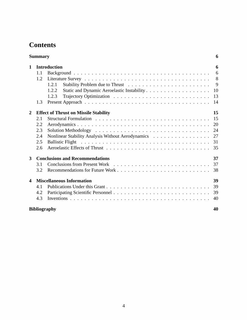
List of Figures
1 Schematic of missile problem . . . . . . . . . . . . . . . . . . . . . . . . .. . . . 82 Typical movement of the center of mass and aerodynamic center . . . . . . . . . . 163 Body drag distribution at supersonic flow . . . . . . . . . . . . . . .. . . . . . . 244 Comparison of slender-body theory with experiments . . . . .. . . . . . . . . . . 255 Time-marching scheme . . . . . . . . . . . . . . . . . . . . . . . . . . . . . . .. 286 Time history above critical thrust . . . . . . . . . . . . . . . . . . . .. . . . . . . 297 Time history below critical thrust . . . . . . . . . . . . . . . . . . . .. . . . . . . 308 Time history well above critical thrust . . . . . . . . . . . . . . . .. . . . . . . . 309 Baseline missile configuration . . . . . . . . . . . . . . . . . . . . . . .. . . . . 3110 Stability for ballistic flight case . . . . . . . . . . . . . . . . . . .. . . . . . . . . 3211 Effect of reduced bending stiffness on stability in ballistic flight . . . . . . . . . . 3312 Static stability showing static margin . . . . . . . . . . . . . . .. . . . . . . . . . 3413 Variation of flexibility . . . . . . . . . . . . . . . . . . . . . . . . . . . .. . . . . 3614 Responses well above and below flutter point . . . . . . . . . . . .. . . . . . . . 36
List of Tables
1 Test case data, ballistic flight . . . . . . . . . . . . . . . . . . . . . . .. . . . . . 31
5
Summary
Statement of the Problem
A current trend in the development of missiles is in the direction of more flexibility, higher ma-neuverability, and higher speeds, all of which require a higher level of fidelity for calculations ofstability, loads, control, and guidance. Unfortunately, until now has been no integrated tool forpreliminary design that considers the related problems that need to be addressed to provide thisincrease in fidelity. To this end, interdisciplinary basic research has been conducted that involvesstructural analysis, dynamics, dynamic stability, aeroelastic stability, and trajectory analysis ofmissiles, rockets, and projectiles.
Most Important Results
A computer code for the dynamic stability, structural dynamics and aeroelastic response of themissile has been written using a geometrically-exact, mixed finite element method. The aerody-namic modeling of the loading for the missile body and fins is based on slender-body theory andthin-airfoil theory, respectively. Results agree with published results for dynamic stability andshow the development of limit cycle oscillations for disturbed flight near and above the criticalthrust. Parametric studies of the aeroelastic behavior of specific flexible missile configurations arepresented, including effects of flexibility on stability, limit-cycle amplitudes, and missile loads.Results indicate little potential for affecting aeroelastic stability by means of composite couplings.However, the results do yield a significant interaction between the thrust, which is a follower force,and the aeroelastic stability. This observation led to additional research on the influence of enginethrust on wing flutter.
1 Introduction
1.1 Background
Missile development design has seen growing emphasis of higher speeds, more demanding maneu-vers, and higher flexibility to meet various mission requirements. For example, several U.S. Armyprograms, such as extended range projectiles, the compact kinetic energy missile (CKEM) and theARROW system require increased maneuverability and flexibility, thus leading to an increase ofthe relative importance of structural loads and deformation in the multidisciplinary problem.
Frequently missiles, rockets, and projectiles must deliver the last ounce of performance in orderto meet their design objectives. For example, projectile designers strive to maximize the payloadthat the system delivers to a specified range; alternatively, they may strive for the maximum rangefor a given payload. Since very small relative changes in total mass may mean large relativechanges in payload mass, even very small margins of gain are important. The extended rangeprojectile program calls for the increase of payload mass bythe use of composites in structural
6
design. Defensive missiles, projectiles that are rocket powered in portions of their flight profiles(such as the CKEM), and smart missiles may be designed to deliver precise hits with maximumfinal kinetic energy or velocity in order to effectively knock out an incoming missile, tank, orother enemy weapon. Greater sophistication in such areas asthe evasive maneuvering capabilityof enemy weapon systems, for example, may require new generations of weapon system to deliverhigher speeds and sustain higher loads and skin temperatures.
It is important to recognize the potential nonlinearities which can arise in both missiles andprojectiles. One source of nonlinearities in missiles is a large axial force, so that even to get thestandard linear equations one must linearize about a nontrivial state. Additional nonlinearities inboth missiles and projectiles can arise due to free-play in threaded and snap joints. Also, fins onmissiles and projectiles have nonlinearities due to large deflections and free-play in the hinges.Further nonlinear effects come about from matter shifting inside the casing. The need to accountfor imperfections and free-play effects provides motivation to base the approach on exact nonlinearkinematics.
Presently, missile conceptual designers specify the stiffness of the missile to structural design-ers. This specification without feedback and iteration doesnot facilitate multidisciplinary designoptimization. Furthermore, even though the designs are driven by stiffness and not by strength, noattempt has been made until now to take advantage of the elastic couplings afforded by use of com-posites. Higher loads are likely to occur due to increased demands placed on modern equipment,and there is a higher probability of the occurrence of staticand dynamic aeroelastic instabilities.Nevertheless, present methodologies are incapable of coping with these problems. Designers mustwait until the prototype stage to see whether or not there aregoing to be aeroelastic problems inthe various flight regimes of the system. This approach is quite wasteful and inefficient.
The above observations also suggest coupling between the flight mechanics, guidance andcontrol of a missile and its structural dynamics and aeroelasticity. A strictly optimal trajectory mayinduce higher internal loads and deformation, and aeroelastic phenomena can affect the originallyplanned missile trajectory. Present methodologies do not allow the exploration of this coupling.The stability problem due to thrust is strictly a dynamic stability issue, but aeroelastic phenomenamay influence it. Unlike conventional flight vehicles, however, the static and dynamic aeroelasticinstabilities may be coupled with flight dynamics modes. It is well known that a static criterionof stability is not sufficient in systems loaded by follower force such as thrust. Thus, a staticallystable missile may be dynamically unstable. Structural deformation may affect the stability, anduse of elastic tailoring may allow the designer to avoid aeroelastic instabilities in the design spaceearly in the design effort.
Recent designs have emphasized the use of composite materials to keep the weight down.As the duration of flight and flight velocity are increased, the rise in casing temperature due toaerodynamic heating may become important. A significant rise in temperature may bring about adegradation in the stiffness properties of the composite materials, particularly in the matrix. Theincreased flexibility may enhance aeroelastic effects, creating non-negligible flexibility effects thatinterfere with the control system’s ability to ensure that the missile or projectile reach precisely thedesired destination.
7
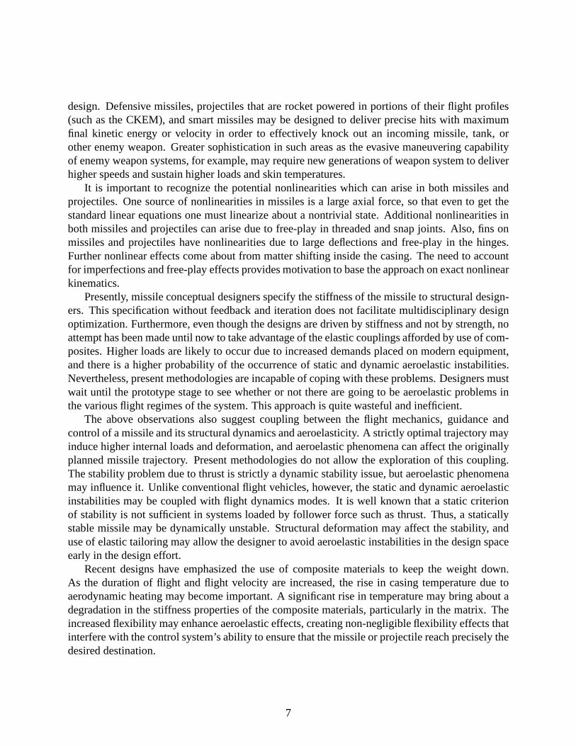
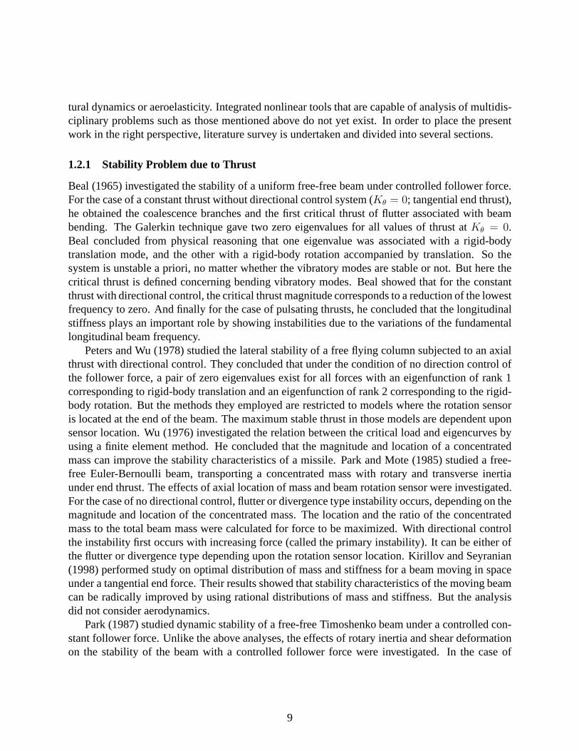
Figure 1: Schematic of missile problem
With these trends in view, it seems imperative that modern analytical tools be created, so thata far better understanding of the influence of missile designparameters and operating conditionson their aeroelastic stability and loads can be obtained. Several issues introduced here will be dis-cussed and their study conducted within one framework, in which the structural part is based on amixed variational formulation which is geometrically exact and based on finite elements and aero-dynamic theories which vary according to the flight regime and missile geometry. The motivationsfor specific aspects of the missile aeroelasticity study aredepicted in Fig. 1.
1.2 Literature Survey
In-flight missiles and projectiles experience various static, dynamic and aeroelastic stability issueswith or without thrusts. But those problems have not had sufficient attention and there were atmost a couple of published attempts to include the effects ofaeroelasticity on the trajectory. Also,the flight mechanics of elastic missiles has seen little attention until recent years. Missiles andprojectiles are typical examples of structures that can be represented by beam models. Indeed,several stability problems related to missiles have been solved mostly by linear beam analyses(Euler-Bernoulli or Timoshenko beam analysis analytically or numerically). However, since thoseapproaches are basically linear, they could not assess the nonlinear features arising from the struc-
8
tural dynamics or aeroelasticity. Integrated nonlinear tools that are capable of analysis of multidis-ciplinary problems such as those mentioned above do not yet exist. In order to place the presentwork in the right perspective, literature survey is undertaken and divided into several sections.
1.2.1 Stability Problem due to Thrust
Beal (1965) investigated the stability of a uniform free-free beam under controlled follower force.For the case of a constant thrust without directional control system (Kθ = 0; tangential end thrust),he obtained the coalescence branches and the first critical thrust of flutter associated with beambending. The Galerkin technique gave two zero eigenvalues for all values of thrust atKθ = 0.Beal concluded from physical reasoning that one eigenvaluewas associated with a rigid-bodytranslation mode, and the other with a rigid-body rotation accompanied by translation. So thesystem is unstable a priori, no matter whether the vibratorymodes are stable or not. But here thecritical thrust is defined concerning bending vibratory modes. Beal showed that for the constantthrust with directional control, the critical thrust magnitude corresponds to a reduction of the lowestfrequency to zero. And finally for the case of pulsating thrusts, he concluded that the longitudinalstiffness plays an important role by showing instabilitiesdue to the variations of the fundamentallongitudinal beam frequency.
Peters and Wu (1978) studied the lateral stability of a free flying column subjected to an axialthrust with directional control. They concluded that underthe condition of no direction control ofthe follower force, a pair of zero eigenvalues exist for all forces with an eigenfunction of rank 1corresponding to rigid-body translation and an eigenfunction of rank 2 corresponding to the rigid-body rotation. But the methods they employed are restrictedto models where the rotation sensoris located at the end of the beam. The maximum stable thrust inthose models are dependent uponsensor location. Wu (1976) investigated the relation between the critical load and eigencurves byusing a finite element method. He concluded that the magnitude and location of a concentratedmass can improve the stability characteristics of a missile. Park and Mote (1985) studied a free-free Euler-Bernoulli beam, transporting a concentrated mass with rotary and transverse inertiaunder end thrust. The effects of axial location of mass and beam rotation sensor were investigated.For the case of no directional control, flutter or divergencetype instability occurs, depending on themagnitude and location of the concentrated mass. The location and the ratio of the concentratedmass to the total beam mass were calculated for force to be maximized. With directional controlthe instability first occurs with increasing force (called the primary instability). It can be either ofthe flutter or divergence type depending upon the rotation sensor location. Kirillov and Seyranian(1998) performed study on optimal distribution of mass and stiffness for a beam moving in spaceunder a tangential end force. Their results showed that stability characteristics of the moving beamcan be radically improved by using rational distributions of mass and stiffness. But the analysisdid not consider aerodynamics.
Park (1987) studied dynamic stability of a free-free Timoshenko beam under a controlled con-stant follower force. Unlike the above analyses, the effects of rotary inertia and shear deformationon the stability of the beam with a controlled follower forcewere investigated. In the case of
9
no directional control, he concluded that the instability at the critical force is of the flutter type,and the critical force increases as shear flexibility increases. With directional control, the primaryinstability type is either flutter or divergence, dependingupon the rotation sensor location andthe magnitude of the sensor gain. From a practical point of view, the effect of rotary inertia wasnegligible.
Because of difficulties in realizing follower forces such asthrust in the laboratory, there hasbeen little progress on finding flutter limit experimentally. Sugiyamaet al. (1995) experimen-tally verified the effect of damping on the flutter of cantilevered column under rocket thrust andexperiment was conducted by the direct installation of a solid rocket motor to the tip end of thecolumns.
Kim and Choo (1998) investigated a Timoshenko beam subjected to a pulsating follower force,previously addressed only by Beal. The effects of axial location and translation inertia of theconcentrated mass are studied, and the relationship between critical forces and widths of instabilityregions in the vicinity of 2ω1 (twice the first natural frequency of bending vibration) arealsoexamined. They concluded that the variation of the instability region near 2ω1 is closely related tothe type of critical force.
It is well known that spinning has a stabilization effect against the directional change of thespinning axis. In a rigid body the stabilization characteristics vary as the spinning speed is in-creased. However, in case of flexible beam model, the stability region may vary due to the effectsof elastic modes. Yoon and Kim (2002) analyzed the dynamic stability of a spinning beam sub-jected to a pulsating thrust. They concluded that the critical load of a free-free beam under constantthrust was not affected by spinning motion, but as the spinning speed was increased, the instabilityregions were reduced.
Leipholz and Piche (1984) studied the effect of weight and follower forces on the stabilityof elastic rods using a two-term Galerkin approximation. Their study included pinned-pinned,clamped-free, and free-free rods. They argued that the representation of the missile mass by as-suming a point-mass model cannot lead to critical loads for divergence and flutter, and that sucha problem can be avoided by making the more general assumption that the mass per unit length isstrictly positive along the entire length of the rod. They showed that instability could be avoidedby careful choice of load direction.
1.2.2 Static and Dynamic Aeroelastic Instability
Linear flight mechanics of spinning projectiles dates back to early 20th century and was extendedafter World War II; see, for example, Foweleret al. (1920), McShaneet al. (1953), and Nicolaides(1953). Platus (1982) reformulated these results in missile-fixed coordinates for reentry vehicles.Later, nonlinear flight mechanics was extensively addressed by Nicolaides (1959), Murphy (1963),Clare (1971), Pepitone and Jacobson (1978), Murphy (1981),and Murphy (1989). Nonlinear flightmechanics of flying missiles still holds an important place in identifying various in-flight problems.
Most material on missile aeroelasticity in the literature is concerned with missile fins than withmissile bodies, because missile fins are more flexible and movable and thereby more likely to be
10
in a condition of flutter before the missile body. For more discussion, Vahdati and Imregun (1997),Cayson and Berry (1990), Murrayet al. (1975), Bae and Lee (2004) deal with the aeroelastic issueson missile fins.
For increasingly flexible missiles there is an increasinglyimportant coupling between so-calledflight dynamics phenomena and aeroelasticity. For example,Matejka (1970) conducted both ana-lytical studies and wind tunnel tests of a two stage Terrier-Tomahawk 9 rocket vehicle. Aeroelasticbending (or more specifically, the adverse movement of the system center of pressure due to ve-hicle flexibility) explains an observed severe reduction instatic stability, rendering the rigid-bodystatic stability criteria insufficient. Both the results ofthe analytical procedure and the wind tunneltests verified that it was possible for the flexible flight vehicle to be in a condition of roll resonanceduring powered flight, while highly stable flight is predicted based on rigid-body considerationsalone.
Moreover, Elyada (1989) studied the aeroelastic divergence of a rocket vehicle in closed form,where roll resonance and trajectory errors can be predicted. Assuming that the accelerations as-sociated with deformation are negligible compared to the ones connected with rigid-body motion,general divergence analyses are considerably simplified. He showed that the short-period modeangular frequency for the flexible missile is always less than that of the associated rigid vehicle.Thus, in a vehicle designed to roll at a frequency smaller than its rigid short-period mode angularfrequency, failure to consider this may result in an unexpected roll resonance. In aerodynamicallymisaligned vehicles, moderating nonlinear effects (or structural failures) occur at substantiallylower dynamic pressures.
There are two kinds of misalignment in missile. One is aerodynamic and the other is thrust.Nakano (1968) conducted study on the bending load due to thrust misalignment. Body divergence,regarded as a phenomenon where the aeroelastic equilibriumwithout stabilizing moment is lost,was analyzed in terms of dynamic pressure and load factor. Heassumed steady-flow aerodynamicsand a straight beam for the missile body, showing the relationship between loads and misalignmentvalues. He concluded that in unguided missiles, the ratio offlight dynamic pressure over diver-gence dynamic pressure should be kept far below than unity because of prediction uncertainty ofaeroelastic parameters or performances and load due to wind.
Crimi (1984) derived from Lagrange’s equations the linear equations of motion for a spinning,aeroelastic missile; however, structural damping was not included in the formulation. He showedthat divergence and dynamic stability are functions of velocity, spin rate and bending stiffness, andthat aeroelastic effects cause degradation of vehicle static longitudinal stability as bending stiffnessis decreased. Platus (1992) derived a nonlinear equation ofmotion for slender, spinning missilesusing a Lagrangean approach that yields a nonlinear terms that produce nonlinear coupling be-tween the elastic deflections and the rigid-body motions. But no attempt is made to assess therelative importance of the nonlinear terms. He showed that missile flexibility on static stabilityreduces the critical frequency for pitch-roll coupling, and viscous structural damping has a desta-bilizing effect on stability at roll rates above the critical frequency for roll-pitch coupling. Oneshould be able to predict the spin and deflection history at any time in flight for a given projectileunder given flight conditions. Stearnset al. (1988) provides such results but details of the analysis
11
and model are not available for verification or review. Legner et al. (1994) studied the primary ef-fects of segmentation (which is used for enhancing the penetrating characteristics of the projectile)and flexure on hypervelocity projectiles, but the details ofthat analysis are also unavailable. Theyshowed effect of the fundamental bending frequency on the angle of attack and the displacementof the projectile tip and concluded that the most significanttip displacement corresponds to regionin time when the angle of attack is maximized, and that increase of bending frequency leads to anincrease of angle of attack. Livshitset al. (1996) studied dynamic aeroelastic analysis of free-flightrockets, incorporating effects of follower forces together with imperfection factors (dynamic im-balance, thrust misalignment and nonlinear fittings) excluding only gyroscopic effects, which aretypical for spin-stabilized types of rockets only. All the loads acting on the rocket were consid-ered as follower forces, including the centrifugal forces coupled with the rocket bending. This isnot correct, as such forces are not dissipative as follower forces are. They showed the resonancetype of instability;i.e., when the spin rate crosses the rocket’s fundamental frequency in bending,the rocket continues to accelerate in roll, developing growing angles of attack after the burnout.They also demonstrated the importance of the imperfections, especially the dynamic imbalanceand thrust misalignment.
Even though structural dynamics of flying missiles is essential in getting structural designrequirements leading to high performance, it has not been dealt with much in the literature incomparison with its importance. The range of missile stiffness should be known at the preliminarydesign phase for optimum design in terms of maneuverabilityand stability. Maloneyet al. (1970)made an extensive study of mechanical joints in common use and investigated their effects onthe flight modes and stiffness. They concluded that tacticalmissile joints play a major role indissipating vibratory energy and the energy dissipation comes from both sliding friction and gaspumping.
Some evidence shows that long-finned missiles, such as some anti-tank kinetic energy projec-tiles, have been forced to spin at rates close to their lowestelastic frequency and have thereforebeen subject to large inelastic deformations. Special solutions showing spin lock-in at the lowestelastic frequency were developed by Mikhail (1996) and Murphy and Mermagen (2000). Mikhailshowed examples of spin lock-in when fin damage produces a roll inducing moment sufficient tocause a steady state spin greater than the lowest elastic frequency and the initial spin rate was zero.However, Murphy and Mermagen (2000) insisted that results obtained by the former should bedismissed due to incorrect expressions for the angular momentum. Murphy and Mermagen (2000)approximated the elastic missile by three rigid bodies connected by two massless elastic beamsand showed that it is impossible to cause spin lock-in by rollinducing moment and zero initialspin alone. It should be noted that the use of the three-body model is a major simplification of theactual physical problem. Later they replaced the three-body model with a continuous elastic modelusing differential equations in Murphy and Mermagen (2000)and obtained numerical results forthe natural frequencies, flexing waveforms and equilibriumspins for a specific missile.
Reis and Sundberg (1967) investigated the causes of large coning angle that a Nike-Tomahawksounding rocket experienced during flight. They assumed that Magnus forces, aeroelastic bending,and/or lee-side boundary separation were probable reasons. Based on flight data they showed that
12
aeroelastic bending was one of the causes. Cochran and Christensen (1979) studied the post-launcheffect of transverse bending of a spinning free-flight rocket during the guidance phase. They usedtwo different methods which are simple two-body model and sophisticated assumed-modes model.
1.2.3 Trajectory Optimization
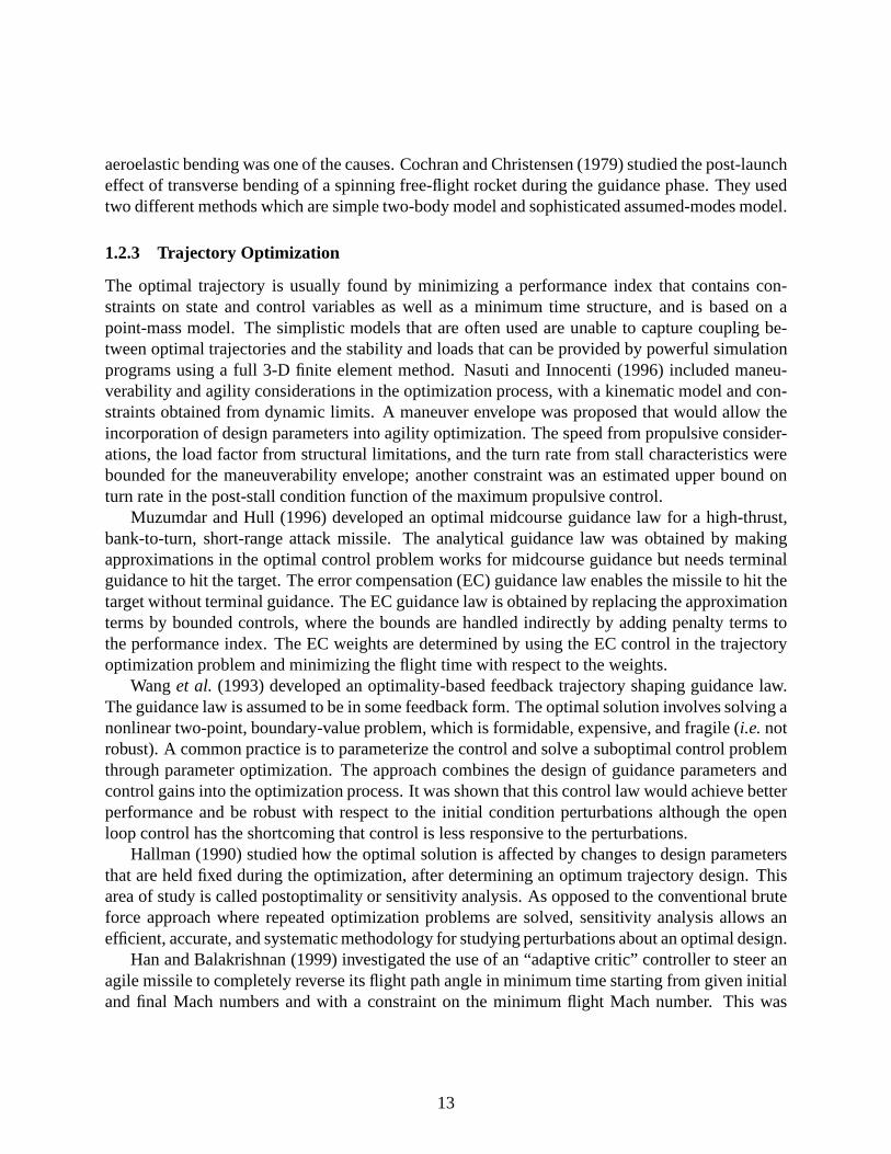
The optimal trajectory is usually found by minimizing a performance index that contains con-straints on state and control variables as well as a minimum time structure, and is based on apoint-mass model. The simplistic models that are often usedare unable to capture coupling be-tween optimal trajectories and the stability and loads thatcan be provided by powerful simulationprograms using a full 3-D finite element method. Nasuti and Innocenti (1996) included maneu-verability and agility considerations in the optimizationprocess, with a kinematic model and con-straints obtained from dynamic limits. A maneuver envelopewas proposed that would allow theincorporation of design parameters into agility optimization. The speed from propulsive consider-ations, the load factor from structural limitations, and the turn rate from stall characteristics werebounded for the maneuverability envelope; another constraint was an estimated upper bound onturn rate in the post-stall condition function of the maximum propulsive control.
Muzumdar and Hull (1996) developed an optimal midcourse guidance law for a high-thrust,bank-to-turn, short-range attack missile. The analyticalguidance law was obtained by makingapproximations in the optimal control problem works for midcourse guidance but needs terminalguidance to hit the target. The error compensation (EC) guidance law enables the missile to hit thetarget without terminal guidance. The EC guidance law is obtained by replacing the approximationterms by bounded controls, where the bounds are handled indirectly by adding penalty terms tothe performance index. The EC weights are determined by using the EC control in the trajectoryoptimization problem and minimizing the flight time with respect to the weights.
Wanget al. (1993) developed an optimality-based feedback trajectoryshaping guidance law.The guidance law is assumed to be in some feedback form. The optimal solution involves solving anonlinear two-point, boundary-value problem, which is formidable, expensive, and fragile (i.e. notrobust). A common practice is to parameterize the control and solve a suboptimal control problemthrough parameter optimization. The approach combines thedesign of guidance parameters andcontrol gains into the optimization process. It was shown that this control law would achieve betterperformance and be robust with respect to the initial condition perturbations although the openloop control has the shortcoming that control is less responsive to the perturbations.
Hallman (1990) studied how the optimal solution is affectedby changes to design parametersthat are held fixed during the optimization, after determining an optimum trajectory design. Thisarea of study is called postoptimality or sensitivity analysis. As opposed to the conventional bruteforce approach where repeated optimization problems are solved, sensitivity analysis allows anefficient, accurate, and systematic methodology for studying perturbations about an optimal design.
Han and Balakrishnan (1999) investigated the use of an “adaptive critic” controller to steer anagile missile to completely reverse its flight path angle in minimum time starting from given initialand final Mach numbers and with a constraint on the minimum flight Mach number. This was
13
undertaken for optimal solutions that encompass perturbations to the assumed initial conditionsor a family of initial conditions. The neighboring optimal control allows pointwise solutions ofan optimal two-point, boundary-value problem to be used with a linearized approximation over arange of initial conditions but can fail outside the regime in which linearization is valid. Dynamicprogramming can handle a family of initial conditions for linear as well as nonlinear problems.Both solution methods are computationally intensive, and the solution is not available in feedbackform. For implementation this becomes a drawback. Outside of dynamic programming, there is nounified mathematical formalism under which a controller canbe designed for nonlinear systems.They proposed a formulation that (1) solves a nonlinear control problem directly without anyapproximation to the system model, (2) yields a control law in a feedback from as a function ofthe current states, and (3) maintains the same structure regardless of the type or problem. Such aformulation is afforded by the field of neural networks, specifically, the adaptive critic architecture.They showed that this method provides optimal control to themissile from an envelope of initialMach numbers in minimum time. An added advantage in using these neurocontrollers is that theyprovide minimum time solutions even when one changes the initial flight path angle from zero toany nonzero (positive) value. Dynamic programming has beenthe main tool for such solutions.
Imado et al. (1990) studied optimal midcourse guidance laws for medium-range, air-to-airmissiles that employ different guidance modes depending onthe required missile velocity andnavigation time. This was done for two separate problems: (1) against a faraway or low-altitudetarget where missile velocity is a prime factor, so that the midcourse guidance law that maximizesthe residual velocity is preferable; (2) against a near target where the time margin is most importantso that the midcourse guidance law that minimizes the interception time is preferable. After therequired missile residual velocity is analyzed against a conventional and an advanced target, fourtypes of midcourse guidance laws depending on objectives are presented, each with its merits anddemerits.
1.3 Present Approach
The aim of the current research is to investigate the effectsof follower forces on aeroelastic sta-bility of missiles. Missile aerodynamics is quite complex,and analytical models cannot exactlysimulate the complex flow under various flight conditions. However, an aerodynamic model that isrepresentative of some typical flight conditions sufficientto see how aerodynamics interacts withthrust. The structural model for the missile is based on the mixed variational formulation. It shouldbe noted that most missile flutter problems shown in the literature have only to do with missile fins.In the present research, our efforts to understand missile body flutter have gone through some dif-ficulty due to extremely limited literature; a rigorous validation thus appears to be impossible.Furthermore, several authors have revealed there are two zero eigenvalues in planar deformationproblems for a free-free beam with a follower force. These zero eigenvalues rigid-body modes;thus one can say, a priori, that free-free beams are neutrally stable in these two rigid-body modes.This does not involve bending of the beam structure. Here thestability analysis is only concernedwith bending modes.
14
The ideas embedded above along with all the works in the literature survey could be exploredwithin one framework which consists of structural formulation and aerodynamic model. The struc-tural formulation is based on finite-element based nonlinear one-dimensional analysis. This finiteelement analysis is very powerful in that it is geometrically exact and allows the use of very simpleshape functions. The most challenging part comes from the aerodynamics which is very depen-dent on the missile geometry and flight conditions. The main idea concerning the present approachto aerodynamic modeling is to buildrepresentative aerodynamic models that are suited to servethe current research purposes with the sacrifice of some accuracy. Thus, analytical, closed-formaerodynamic expressions or at least less computational methods such as the modified Newtonianmethod or piston theory are preferred. Another thing to be said about missile aerodynamics expres-sions is that differentiated variables should be expressedin other kinematic variables in keepingwith the lowest order of differentiations in the structuralformulation. The follower force causedby missile thrust has its own instabilities without consideration of an aerodynamic model, and thesame observation applies also to aeroelastic instabilities without consideration of the effects of thefollower force. Therefore, the interactions of follower forces and aerodynamic forces make onethink of the possible stability boundaries suggested by Leipholz (1980) and Huseyin (1978).
2 Effect of Thrust on Missile Stability
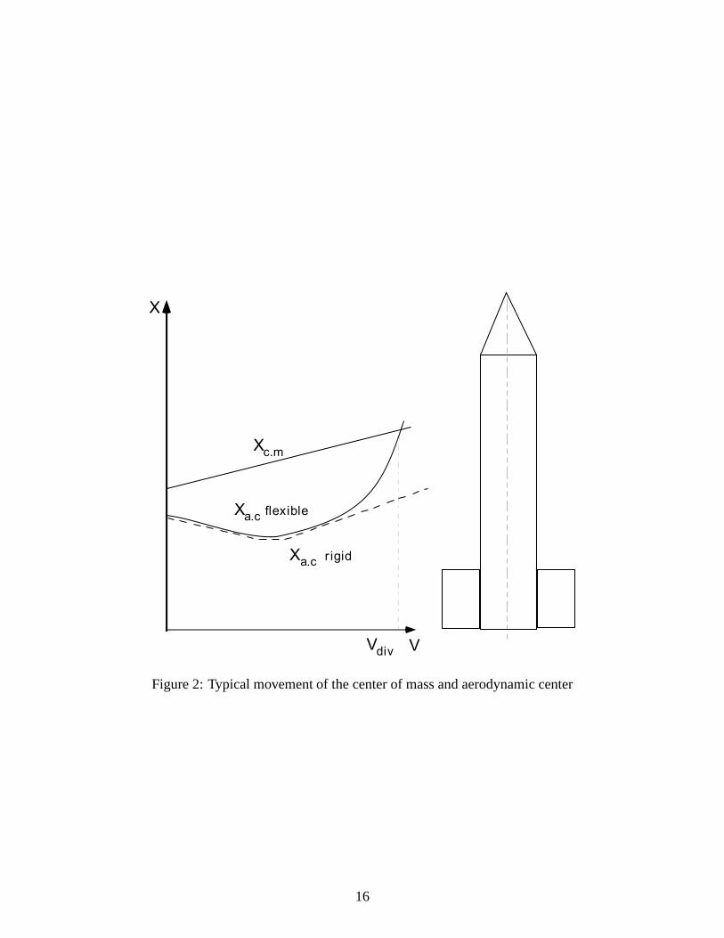
Missile flight can be divided into two phases, powered flight and free flight without thrust. Dur-ing powered flight, loads and dynamic stability are the main issues. Projectiles are under severestresses. Total mass varies from propellant consumption and aerodynamic center changes as welldue to possible bending deformation from considerable lifton both nose and tail and the variationof aerodynamic coefficients. There is a certain velocity where the shifted location of the aerody-namic center coincides with the location of the center of mass. But this situation can be avoided bykeeping the burnout velocity below that velocity. Such a variation trend that is depicted in Livshitsand Yaniv (1999) is introduced for clarification in Fig. 2 formovement of the missile center ofmass and aerodynamic center for both rigid- and flexible-body models as a function of velocity.
During powered flight, the missile reaches its maximum speed, the so-called burnout velocity.After reaching the burnout velocity, the missile decelerates. Therefore, accelerating flight withthrust, steady flight when the thrust magnitude is equal to drag, and ballistic flight without thrustare of interest to current research efforts.
2.1 Structural Formulation
The structural part of the formulation comes from the mixed variational formulation based on theexact intrinsic equations for dynamics of moving beams presented by Hodges (1990). Modifica-tions of the original variational principle necessary for the present study are the inclusion of thegravitational potential energy and appropriate energy variation for dealing with rigid-body dynam-ics, the analysis of which is needed for the missile time-marching scheme. The frames presented
15
V
X
Xc.m
Xa.c flexible
Vdiv
Xa.c r igid
Figure 2: Typical movement of the center of mass and aerodynamic center
16
here are the undeformed beam cross-sectional frame (theb basis), the deformed cross-sectionalframe (theB basis), and the inertial frame (thei basis). Here we follow the same rule for thevariable notation as shown by Hodges (1990), except that thesubscripto represents the missilereference point for taking care of rigid-body motion. The variables with subscriptb and o aremeasured in theb frame, except foruo, the basis for which is the inertial frame. The variationalformulation starts with extended Hamilton’s principle
∫ t2
t1
∫ l
0
[δ(K − U) + δW
]dx1 dt = δA (1)
wheret1 andt2 specify the time interval over which the solution is sought;K andU are the kineticand strain energy densities per unit length, respectively;andδA is the virtual action at the ends ofthe beam and at the ends of the time interval. The contribution of all gravitational forces is handledby means of its potential energy, which is written as
G =
∫ `
0
mgeT3
[uo + CT
o (rb + ub + CT ξB)]dx1 (2)
where the superscriptT indicates the transpose of a matrix,e3 = b0 0 1cT , rb is the position fromthe missile body reference point,uo is the displacement of missile reference point in thei frame,ub is the displacement of the points on missile reference line in theb frame,ξB is the mass offsetfrom the missile reference line,m is mass per unit length,Co is the rotation matrix fromi frameto b frame, andC is the rotation matrix fromb frame toB frame. The kinematic relationships andthe expressions for the velocities and the generalized strains can be written as
vo = Couo (3)
ωo = −CoCTo (4)
VB = C [vo + ub + ωo(rb + ub)] (5)
ΩB =
(∆ −
eθ2
1 + θT θ4
)θ + Cωo (6)
γ = C(e1 + u′b) − e1 (7)
κ =
(∆ −
eθ2
1 + θT θ4
)θ′ (8)
where the( ) operator converts a 3×1 column matrix, sayv = bv1 v2 v3cT , to its 3×3 antisym-
metric dual matrix
v =
0 −v3 v2
v3 0 −v1
−v2 v1 0
(9)
e1 = b1 0 0cT , ˙( ) and( )′ are differentiations with respect to time andx1, respectively. Theorientation of theB frame with respect to theb frame is represented using Rodrigues parameters,
17
which have been applied to nonlinear beam problems with success. The rotation matrix relatingtheB frame to theb frame is written as
C =
(1 − 1
4θT θ)∆ − θ + 1
2θθT
1 + 1
4θT θ
(10)
For the orientation of the missile body frame (i.e. theb frame), however, the regular use of theRodrigues parameters is insufficient because of their well-known singularity at a rotation angle of180. Thus, the direction cosines ofb in i are used as rotational variables for the rigid-body motionof the missile. The strain and force measures, along with velocity and momentum measures, arerelated through the constitutive laws in the form
PH
=
[m∆ −mξ
mξ I
]VΩ
FM
= [S]
γκ
(11)
All the elastic virtual variations are the same as the expressions in Hodges (1990) except forthe virtual quantities related to rigid-body variables. Here the details of the rigid-body part aredescribed. After some manipulations, the virtual variations of rigid-body variablesvo andωo inEqs. (3) and (4) may be expressed as
δvo = ˙δqo + ωoδqo + voδψo (12)
δωo = ˙δψo + ωoδψo (13)
whereδqo andδψo are virtual quantities defined in theb frame,i .e. δqo = Coδuo. Also, Eq. (2)can be expressed as
δG =δqTo Co
∫ `
0
mge3dx1 − δψTo Coe3
∫ `
0
mg(rb + ub + CT ξB)dx1
+
∫ `
0
δqT
BCCoe3mgdx1 +
∫ `
0
δψT
B ξBCCoe3mgdx1
(14)
Adding the varying action and virtual work terms contributed by the rigid-body variables, one findsthat
δAo = (δqTo Po + δψT
o Ho)
∣∣∣∣t2
t1
(15)
δW o = δqTo fo + δψT
o mo (16)
18
wherefo andmo are column matrices containing the measure numbers of forceand moment vec-tors acting on the reference point in theb frame; Po andHo are linear and angular momenta ofreference point at the ends of specified time interval in theb frame. Additional terms of elasticvirtual quantities stemming from rigid-body variations are
δV TB : δvT
o CT + δωT
o (rb + ub)CT (17)
δΩTB : δωT
o CT (18)
For the variations of individual energies, and virtual workdone on the system, we have
δK = δvTo Po + δωT
o Ho +
∫ l
0
(δV TB PB + δΩT
BHB)dx1 (19)
δU = δG+
∫ l
0
(δγTFB + δκTMB)dx1 (20)
δW = δqTo fo + δψT
o mo +
∫ l
0
(δqT
BfB + δψT
BmB)dx1 (21)
where the unknowns areFB andMB, the sectional force and moment measures in theB basis,respectively;PB andHB, the sectional linear and angular momentum measures in theB basis,respectively;γ and κ, the force and moment strains, respectively;VB and ΩB, the linear andangular velocity measures of the beam reference line in theB basis, respectively; andfB andmB,the external force and moment, respectively.
The expressions for various virtual quantities such asδVB, δΩB, δγ, andδκ are substitutedinto the energy equations. In the mixed variational formulation, the appropriate kinematical andconstitutive relations are enforced as additional constraints using Lagrange multipliers and are thenadjoined to Hamilton’s weak principle expressed in terms ofgiven energies.
19
The modified weak form from the original mixed variational formulation including the rigid-body part in the proper way then can be written as
∫ t2
t1
∫ `
0
[δq
′T
B − δqT
Bκ− δψT
B(e1 + γ)]FB +
(δψ
′T
B − δψT
Bκ)MB
−
[δq
T
B − δqT
BΩB − δψTVB + δvT
o CT
+ δωTo (rb + ub)C
T
]PB −
(˙δψ
T
B − δψΩB + δωTo C
T
)HB
+ δFT [e1 − CT (e1 + γ)
]− δF
′Tub
− δMT
(∆ +
1
2θ +
1
4θθT
)κ− δM
′Tθ
− δPT [vo + ωo(ro + ub) − CTVB
]+ ˙δP
T
ub
− δHT
(∆ +
1
2θ +
1
4θθT
)(Cω − ΩB)
+ ˙δHT
θ − δqT
BfB − δψT
BmB
dx1dt
+
∫ t2
t1
(δG∗ − δv∗
T
o Po − δω∗T
o Ho − δqTo fo − δψT
o mo
)dt
= −
∫ `
0
(δq
T
BPB + δψBHB −δPTub − δH
Tθ
)∣∣∣∣t2
t1
dx1
+
∫ t2
t1
(δq
TF + δψ
TM −δF
Tu− δM
Tθ
)∣∣∣∣`
0
dt−
(δqT
o Po + δψTo Ho
)∣∣∣∣t2
t1
(22)
where algebraic expressions defining certain variables in terms of displacement and rotation vari-ables are denoted by( )∗ and ˆ( ) represents discrete boundary values either at the ends of beam orat the ends of time interval. In addition to the above formulation, Poisson equation (Co+ωoCo = 0)of direction cosine matrix is adjoined using Lagrange multipliers, which is not included here forthe sake of brevity.
2.2 Aerodynamics
Available aerodynamics tools have been evaluated for computation of loads on missiles. Missileloads are very dependent on the flight condition and missile geometry. Several technical methodsare extensively described in Mooreet al. (1998), Nielsen (1988), and Moore (2000). The validityof slender-body theory, which is based on potential flow, hasbeen well established by compari-son with experimental data in Allen and Perkins (1951) for a wide range of Mach numbers. An
20
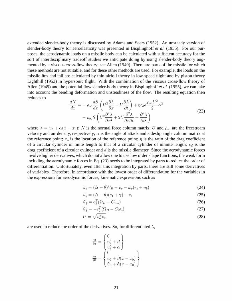
extended slender-body theory is discussed by Adams and Sears (1952). An unsteady version ofslender-body theory for aeroelasticity was presented in Bisplinghoff et al. (1955). For our pur-poses, the aerodynamic loads on a missile body can be calculated with sufficient accuracy for thesort of interdisciplinary tradeoff studies we anticipate doing by using slender-body theory aug-mented by a viscous cross-flow theory; see Allen (1949). There are parts of the missile for whichthese methods are not suitable, and for these other methods are used. For example, the loads on themissile fins and tail are calculated by thin-airfoil theory in low-speed flight and by piston theoryLighthill (1953) in hypersonic flight. With the combinationof the viscous cross-flow theory ofAllen (1949) and the potential flow slender-body theory in Bisplinghoffet al. (1955), we can takeinto account the bending deformation and unsteadiness of the flow. The resulting equation thenreduces to
dN
dx= − ρ∞
dS
dx
(U2∂λ
∂x+ U
∂λ
∂t
)+ ηcdd
ρ∞U2
2α2
− ρ∞S
(U2∂2λ
∂x2+ 2U
∂2λ
∂x∂t+∂2λ
∂t2
) (23)
whereλ = ub + α(x − xo); N is the normal force column matrix;U andρ∞ are the freestreamvelocity and air density, respectively;α is the angle of attack and sideslip angle column matrix atthe reference point;xo is the location of the reference point;η is the ratio of the drag coefficientof a circular cylinder of finite length to that of a circular cylinder of infinite length;cd is thedrag coefficient of a circular cylinder andd is the missile diameter. Since the aerodynamic forcesinvolve higher derivatives, which do not allow one to use loworder shape functions, the weak formincluding the aerodynamic forces in Eq. (23) needs to be integrated by parts to reduce the order ofdifferentiation. Unfortunately, even after this integration by parts, there are still some derivativesof variables. Therefore, in accordance with the lowest order of differentiation for the variables inthe expressions for aerodynamic forces, kinematic expressions such as
ub = (∆ + θ)VB − vo − ωo(rb + ub) (24)
u′b = (∆ − θ)(e1 + γ) − e1 (25)
u′2 = eT3 (ΩB − Cωo) (26)
u′3 = −eT2 (ΩB − Cωo) (27)
U =√vT
o vo (28)
are used to reduce the order of the derivatives. So, for differentiatedλ,
∂λ∂x
=
0u′2 + βu′3 + α
∂λ∂t
=
0
u2 + β(x− x0)u3 + α(x− x0)
21
In order to completely determine the angle of attack and sideslip angle quantities in terms ofother kinematic quantities, we need to obtain the rotation matrix from the inertial frame to the windframe,CWI . From the frame definitions,
q1q2q3
=
CWI
11
CWI12
CWI13
=
∆
UCT
o vo (29)
If θw is defined as a column matrix of Rodrigues parameters, we can obtain
θw = θw1e1 +1
1 + q1[2e1 + θw1(∆ − e1e
T1 )]CIWe1 (30)
as given by Hodges (1990). After a holonomic constraint,θw1=0 is imposed, we obtain
θw =2
1 + q1
0−q3q2
(31)
so that q1q2q3
=
∆
U2[CT
o ωovo + CTo aU −
CTo vov
To a
U] (32)
and
θw =2
(1 + q1)2
0−q3(1 + q1) + q3q1q2(1 + q1) − q2q1
(33)
Thus, if one can get the one row components of rotation matrixCWI from Eq. (29), rotation matrixCWI and angular velocity of wind frame with respect to inertial frame can be determined as follows
CWI =
(1 − 1
4θT
wθw
)∆ − θw + 1
2θwθ
Tw
1 + 1
4θT
wθw
(34)
ωWI =(∆ − θw
2)
1 + θTwθw
4
θw (35)
SinceCbW = CoCIW andCIW = CIW ωWI , it then follows that
CbW = −ωoCoCIW + CoC
IW ωWI (36)
Then, we can findα, β, α and β in terms of different variables. It should be noted that as thedefinition ofλ implies, we still have local angles of attack varying along the missile even whenthe rigid-body angle of attack at the reference point is zero. That leads to the idea that in simplerectilinear flight, a missile can still experience aeroelastic deformation in various speed ranges.
22
The above slender-body aerodynamics is thought to be relatively useful at the flight range belowMach 5 since above 5, more advanced and complicated aerodynamics caused by aerodynamicheating will be needed. Also, most full-scale missiles operates at below Mach 4, so the currentaerodynamics will be used in flight speed range between Mach 2and Mach 5.
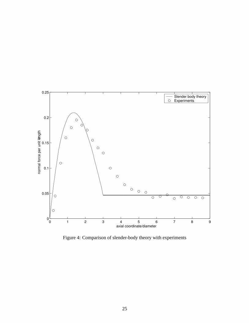
Results according to above formulation are in good agreement with existing experimental data.Fig. 4 represents the comparison between slender-body theory and experiments from Lordonet al.(1990) for steady flow when the angle of attack is10. The average normal force and pitchingmoment are in excellent agreement and the distributed forceshows sufficiently good agreementfor the purposes of our current research.
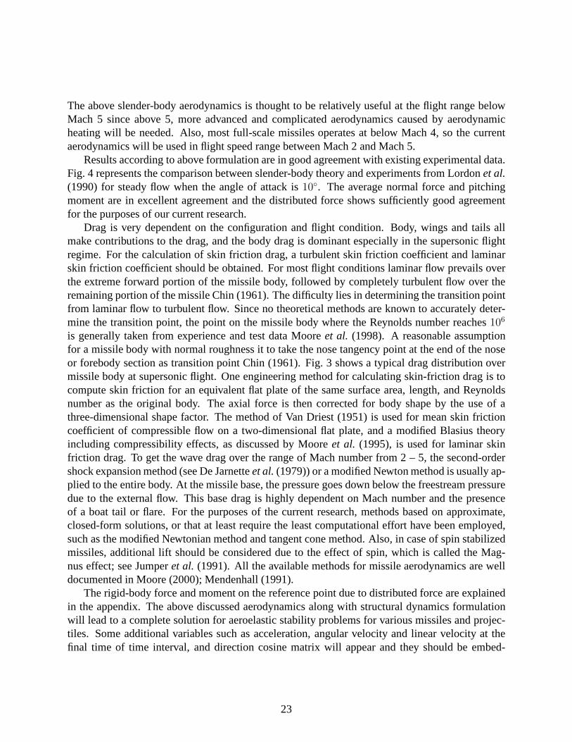
Drag is very dependent on the configuration and flight condition. Body, wings and tails allmake contributions to the drag, and the body drag is dominantespecially in the supersonic flightregime. For the calculation of skin friction drag, a turbulent skin friction coefficient and laminarskin friction coefficient should be obtained. For most flightconditions laminar flow prevails overthe extreme forward portion of the missile body, followed bycompletely turbulent flow over theremaining portion of the missile Chin (1961). The difficultylies in determining the transition pointfrom laminar flow to turbulent flow. Since no theoretical methods are known to accurately deter-mine the transition point, the point on the missile body where the Reynolds number reaches106
is generally taken from experience and test data Mooreet al. (1998). A reasonable assumptionfor a missile body with normal roughness it to take the nose tangency point at the end of the noseor forebody section as transition point Chin (1961). Fig. 3 shows a typical drag distribution overmissile body at supersonic flight. One engineering method for calculating skin-friction drag is tocompute skin friction for an equivalent flat plate of the samesurface area, length, and Reynoldsnumber as the original body. The axial force is then corrected for body shape by the use of athree-dimensional shape factor. The method of Van Driest (1951) is used for mean skin frictioncoefficient of compressible flow on a two-dimensional flat plate, and a modified Blasius theoryincluding compressibility effects, as discussed by Mooreet al. (1995), is used for laminar skinfriction drag. To get the wave drag over the range of Mach number from 2 – 5, the second-ordershock expansion method (see De Jarnetteet al. (1979)) or a modified Newton method is usually ap-plied to the entire body. At the missile base, the pressure goes down below the freestream pressuredue to the external flow. This base drag is highly dependent onMach number and the presenceof a boat tail or flare. For the purposes of the current research, methods based on approximate,closed-form solutions, or that at least require the least computational effort have been employed,such as the modified Newtonian method and tangent cone method. Also, in case of spin stabilizedmissiles, additional lift should be considered due to the effect of spin, which is called the Mag-nus effect; see Jumperet al. (1991). All the available methods for missile aerodynamicsare welldocumented in Moore (2000); Mendenhall (1991).
The rigid-body force and moment on the reference point due todistributed force are explainedin the appendix. The above discussed aerodynamics along with structural dynamics formulationwill lead to a complete solution for aeroelastic stability problems for various missiles and projec-tiles. Some additional variables such as acceleration, angular velocity and linear velocity at thefinal time of time interval, and direction cosine matrix willappear and they should be embed-
23
Transition point Reynolds number 10
Wave Drag
Thrust
6
Bow Shock
Base drag
Turbulent flow
aminar flowL
Figure 3: Body drag distribution at supersonic flow
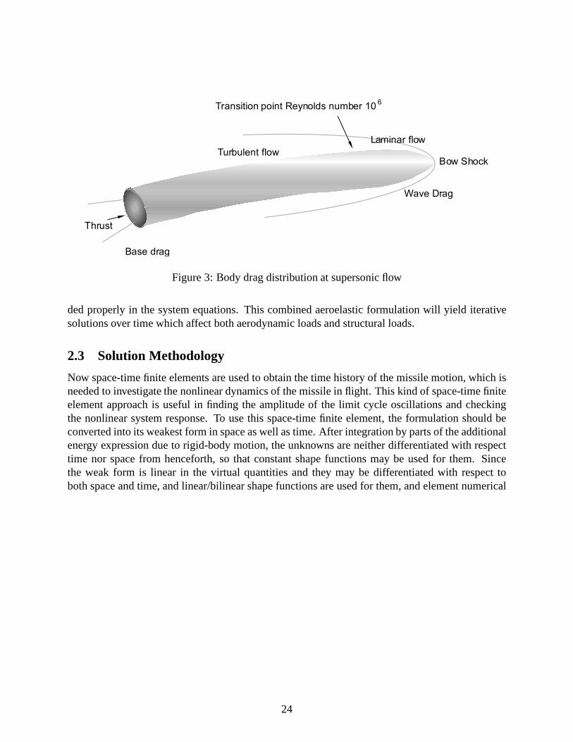
ded properly in the system equations. This combined aeroelastic formulation will yield iterativesolutions over time which affect both aerodynamic loads andstructural loads.
2.3 Solution Methodology
Now space-time finite elements are used to obtain the time history of the missile motion, which isneeded to investigate the nonlinear dynamics of the missilein flight. This kind of space-time finiteelement approach is useful in finding the amplitude of the limit cycle oscillations and checkingthe nonlinear system response. To use this space-time finiteelement, the formulation should beconverted into its weakest form in space as well as time. After integration by parts of the additionalenergy expression due to rigid-body motion, the unknowns are neither differentiated with respecttime nor space from henceforth, so that constant shape functions may be used for them. Sincethe weak form is linear in the virtual quantities and they maybe differentiated with respect toboth space and time, and linear/bilinear shape functions are used for them, and element numerical
24
0 1 2 3 4 5 6 7 8 90
0.05
0.1
0.15
0.2
0.25
axial coordinate/diameter
norm
al fo
rce p
er
unit length
h
Slender body theoryExperiments
Figure 4: Comparison of slender-body theory with experiments
25
quadrature is not needed. Thus,
δqB = δqis(1 − ξ)(1 − τ) + δqif
(1 − ξ)τ
+ δqi+1sξ(1 − τ) + δqi+1f
ξτ u = ui
δψB = δψis(1 − ξ)(1 − τ) + δψif
(1 − ξ)τ
+ δψi+1sξ(1 − τ) + δψi+1f
ξτ θ = θi
δF = δF i(1 − ξ) + δF i+1ξ F = Fi
δM = δM i(1 − ξ) + δM i+1ξ M = Mi
δP = δP is(1 − τ) + δP if τ P = Pi
δH = δH is(1 − τ) + δH if τ H = Hi
δqo = δqos(1 − τ) + δqofτ
δψo = δψos(1 − τ) + δψofτ
where subscriptss andf denote the variable values at the starting and final time of time interval.After some manipulations it can be shown that some of the resulting discretized equations arelinear combinations of the others, leaving us free to discard the excess equations. For illustrativepurposes, we consider only the structural part for the time being. Then,
δqif P i =Pif + Pis
2
δψif Hi =Hif + His
2
δP if ui =uif + uis
2
δH if θi =θif + θis
2
δqn+1 F i =Fi + Fi+1
2
δψn+1 M i =Mi + Mi+1
2
δF n+1 ui =ui + ui+1
2
δMn+1 θi =θi + θi+1
2
δqof P o =Pof + Pos
2
δψof Ho =Hof + Hos
2
26
By virtue of these relations, the number of unknowns corresponding to each virtual quantity isreduced. Then, the total number of equations related to elastic variables;δqis, δψis, δP is, δHis,δF i, δM i (i=1 to n), is 18n. The total number of equations defining rigid-body motion relatedto δqos(3), δψos(3), δvo(3), δωo(3), is 12 if we do not consider direction cosine and accelerationvariables. Unknown variables areFi, Mi, Pif , Hif , uif , θif , Pof , Hof , vo, ωo after specifyingboundary conditions (Fn+1, Mn+1 and u1, θ1) and initial conditions (Pis, His, uis, θis, Pos, Hos)for each element, therefore in total 18n +12. The above discussion shows that the total number ofequations and the total number of unknowns are equal.
With these system equations and unknown variables, if we just consider structural dynamics,the mixed variational formulation takes the form
F (Xs, Xf , X) = 0 (37)
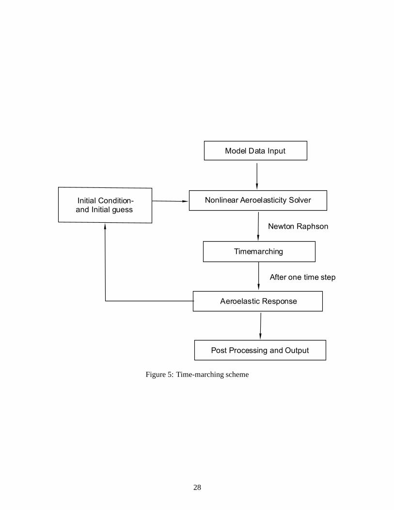
whereX is a column matrix of all structural variables andXs andXf are its initial and final values.This nonlinear algebraic equation can be solved by Newton-Raphson. The Jacobian matrix of theabove set of nonlinear equations can be obtained analytically or numerically and is found to beextremely sparse due to the formulation’s weakest form. This helps to obtain the high computa-tional efficiency. So, if the initial conditions and boundary conditions are specified, the final valuesafter one time step can be found very efficiently using the damped Newton-Raphson method, andtime history is obtained by doing time marching iteration. The structural part of the above formu-lation has been well validated against the stability subject to thrust. Fig. 5 shows more specifictime-marching scheme.
Apart from the above discussion, several issues on computational stability and efficiency shouldbe addressed. First, the kinematic quantities for initial conditions should satisfy certain kinemat-ical relations since they are not independent. So if one variable is perturbed, other variables areaffected; that is, all the kinematic quantities which are related to it should have modified values.This is an important aspect of the formulation, since it predominantly affects the sensitivity andconvergence of the solution for the time-marching scheme. Second, depending on the type ofproblems proposed, some variables can be added or removed for computational efficiency. For ex-ample, for rectilinear flight, direction cosine variables would not be needed. Missile aerodynamicsdiscussed will need additional variables and equations such as acceleration and direction cosinesand related equations.
2.4 Nonlinear Stability Analysis Without Aerodynamics
Based on the methodology set forth here, a computer code for investigation of the nonlinear dy-namics of a missile has been developed. The various stability problems due to thrust which appearin the literature can be examined in terms of their time history. First, for validation purpose of thecurrent work, the case without directional control considered by Beal (1965) is addressed. Since itis known that the mass distribution also contributes to the critical load for thrust, constant mass willbe considered for a comparison purpose. When a small perturbation of the transverse deflection isimposed at the initial time and the thrust level is below Beal’s critical value, the deflection indeed
27
Model Data Input
Nonlinear Aeroelasticity Solver
Timemarching
Aeroelastic Response
Initial Condition- and Initial guess
After one time step
Post Processing and Output
Newton Raphson
Figure 5: Time-marching scheme
28
0 0.5 1 1.5 2 2.5 3 3.5 4 4.5 51. 5
1
0. 5
0
0.5
1
1.5
time. s
dis
pla
cem
ent at m
idpoin
t, %
of m
issile
length
Figure 6: Time history above critical thrust
29
Figure 7: Time history below critical thrust
Figure 8: Time history well above critical thrust
30
STA 60.8
19.4
3.418.5
STA 125.4
LEMAC at STA 67.0BL 10.2
Λ= 45°
40.2
STA 0 19.2 46.1 62.6 84.5 138.6
Nose Forebody Payload
Bay
Midbody Aftbody Tailcone
Rocket Motor
Λ= 57°
12.0
LEMAC at
STA 131.6BL 8.0
16.18.0 d
cgBO cgLaunch
143.9
STA 60.8
19.4
3.418.5
STA 125.4
LEMAC at STA 67.0BL 10.2
45°
40.2
STA 0 19.2 46.1 62.6 84.5 138.6
Nose Forebody Payload
Bay
Midbody Aftbody Tailcone
Rocket Motor
57°
12.0
LEMAC at
STA 131.6BL 8.0
16.18.0 d
cgBO cgLaunch
143.9
Figure 9: Baseline missile configuration
Table 1: Test case data, ballistic flight
Bending Stiffness: uniform 2×10⁶N-m2
Altitude: 20 kmDensity: 0.0889 kg/m3
Temperature: 216.7K
dies out in time. However, as expected, when the thrust levelis a little larger than the critical value,the deflections grow until they reach an oscillatory motion with bounded amplitude, suggesting alimit cycle. A typical result is shown in Fig. 6. Results for several cases show that limit cycles candevelop from disturbances with thrust values that are either just below the critical value suggestedby Beal (1965) (Fig. 7) or just above it. However, the motion is divergent well above the criticalvalue as shown in Fig. 8. This observation serves to partially validate the current approach.
2.5 Ballistic Flight
To see if there are any aeroelastic effects on the stability as a function of thrust or on acceleratedflight, Fig. 9 is used as a baseline missile configuration; seeBithell and Stoner (1982). Bothmovable and fixed tail fins with a cruciform pattern have two sets of wedge-shaped panels. Aroundthe nose, the large missile body drag is applied. The fins and tail are both under the influence ofwave drag and skin friction drag. At the nozzle base, base drag and thrust are both applied. Thetotal drag force is distributed along the body. Here it should be noted that missile fins are not aconsideration for stability because we are interested in only missile body bending modes. Theloads on the fins are applied as concentrated forces. In reality, missile fin flutter is more common
31
Mach 4.0
Mach 3.0
Mach 3.5
Figure 10: Stability for ballistic flight case
32
1.2
Figure 11: Effect of reduced bending stiffness on stabilityin ballistic flight
33
X
Xc.m
Xc.p f lexible
assumed constant
M
static marg in for flexib le body
3 4.0 4.53.5
loca
tio
n f
rom
tail
Figure 12: Static stability showing static margin
34
phenomena since fins are more flexible compared to the missilebody. But the purpose of thisresearch is to identify how bending of the missile body affects aeroelastic stability. Therefore,this assumption will be maintained under the current research. The basic idea about how theaeroelastic phenomena occur is that missile bending will change the local angle of attack on thebody and the changed local of attack will in turn give different aerodynamic loads on the missile,which will further deform the missile. This iterative process of yielding new aerodynamic loadsand deforming the missile will result in stable or unstable flight depending on the various flightconditions and missile characteristics.
When the thrust force is balanced with the total drag, the missile maintains equilibrium by fly-ing at constant speed. But depending on whether the thrust force magnitude is bigger or smallerthan the total drag, the missile either accelerates or decelerates. First the aeroelastic stability ofmissile flying at high supersonic velocity will be addressed. Once velocity is specified, the missiledrag is determined from unsteady aerodynamics for missiles. The initial flight condition satisfyingkinematic relations and initial deflection for bending are given to run this case. Fig. 10 shows thebending response in rectilinear flight for the test case fromTable 1. The case represents decelera-tion from steady-state flight. The responses showed that there was no aeroelastic instability for theuniform bending stiffness in this test case. With a very small time interval, less than one secondwas good enough to identify the decay. The velocity increasenoticeably affects the amplitudes ofthe response after small lateral disturbances are given. The flexural stiffnesses are relatively large,but the distributed drag forces appear to play the role of reducing the effective stiffness. To see theeffect of bending stiffness on aeroelastic stability in ballistic flight, the size of bending stiffnesswas reduced to about 1/100 of the original value. Fig. 11 shows limit cycle at the same Mach4.0. One can see the conspicuous effect of bending stiffnesson the aeroelastic stability at ballisticflight.
Under the current formulation, the total mass of the missiledoes not change. Thus, the centerof mass location along the missile axis is assumed to be constant, and the center of pressure ofmissile can be calculated from running the code. From Fig. 12one can see that this flexible missilebody model is statically stable. In reality the missile center of mass moves closer to missile noseas the fuel is consumed. Therefore, the body will have a little larger static margin.
2.6 Aeroelastic Effects of Thrust
As shown in previous sections, thrust and aerodynamic forces themselves have a destabilizingeffect on the missile stability. Aeroelastic interactionsbetween structural load, aerodynamic load,and inertial load are a continuous iterative process between each load. That is, the missile bendingbrought on by aerodynamic normal forces will change the local angles of attack along the missilebody. Altered angles of attack will, in turn, change the aerodynamic forces on the missile body.That will yield additional inertial loading over the missile body. And these inertial loading furtherdeforms the missile body. During this iteration, the missile will reach an equilibrium state whereall the forces are balanced.
Besides all this, thrust will also influence the results. It is natural to ask how thrust interacts
35
2 x10 N - m
2 x10 N - m
2
24
6
Figure 13: Variation of flexibility
outside boundary
inside boundary
Figure 14: Responses well above and below flutter point
36
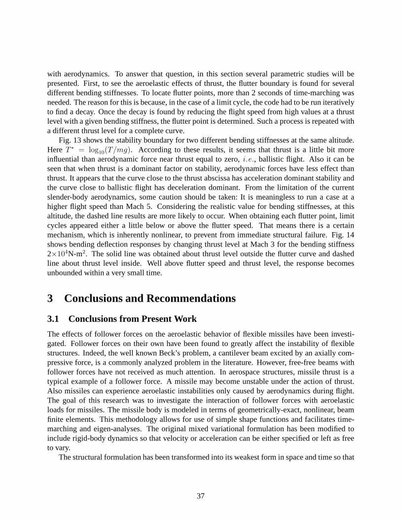
with aerodynamics. To answer that question, in this sectionseveral parametric studies will bepresented. First, to see the aeroelastic effects of thrust,the flutter boundary is found for severaldifferent bending stiffnesses. To locate flutter points, more than 2 seconds of time-marching wasneeded. The reason for this is because, in the case of a limit cycle, the code had to be run iterativelyto find a decay. Once the decay is found by reducing the flight speed from high values at a thrustlevel with a given bending stiffness, the flutter point is determined. Such a process is repeated witha different thrust level for a complete curve.
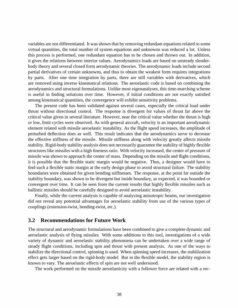
Fig. 13 shows the stability boundary for two different bending stiffnesses at the same altitude.Here T ∗ = log10(T/mg). According to these results, it seems that thrust is a littlebit moreinfluential than aerodynamic force near thrust equal to zero, i .e., ballistic flight. Also it can beseen that when thrust is a dominant factor on stability, aerodynamic forces have less effect thanthrust. It appears that the curve close to the thrust abscissa has acceleration dominant stability andthe curve close to ballistic flight has deceleration dominant. From the limitation of the currentslender-body aerodynamics, some caution should be taken: It is meaningless to run a case at ahigher flight speed than Mach 5. Considering the realistic value for bending stiffnesses, at thisaltitude, the dashed line results are more likely to occur. When obtaining each flutter point, limitcycles appeared either a little below or above the flutter speed. That means there is a certainmechanism, which is inherently nonlinear, to prevent from immediate structural failure. Fig. 14shows bending deflection responses by changing thrust levelat Mach 3 for the bending stiffness2×104N-m2. The solid line was obtained about thrust level outside the flutter curve and dashedline about thrust level inside. Well above flutter speed and thrust level, the response becomesunbounded within a very small time.
3 Conclusions and Recommendations
3.1 Conclusions from Present Work
The effects of follower forces on the aeroelastic behavior of flexible missiles have been investi-gated. Follower forces on their own have been found to greatly affect the instability of flexiblestructures. Indeed, the well known Beck’s problem, a cantilever beam excited by an axially com-pressive force, is a commonly analyzed problem in the literature. However, free-free beams withfollower forces have not received as much attention. In aerospace structures, missile thrust is atypical example of a follower force. A missile may become unstable under the action of thrust.Also missiles can experience aeroelastic instabilities only caused by aerodynamics during flight.The goal of this research was to investigate the interactionof follower forces with aeroelasticloads for missiles. The missile body is modeled in terms of geometrically-exact, nonlinear, beamfinite elements. This methodology allows for use of simple shape functions and facilitates time-marching and eigen-analyses. The original mixed variational formulation has been modified toinclude rigid-body dynamics so that velocity or acceleration can be either specified or left as freeto vary.
The structural formulation has been transformed into its weakest form in space and time so that
37
variables are not differentiated. It was shown that by removing redundant equations related to somevirtual quantities, the total number of system equations and unknowns was reduced a lot. Unlessthis process is performed, one redundant equation has to be chosen and thrown out. In addition,it gives the relations between interior values. Aerodynamics loads are based on unsteady slender-body theory and several closed form aerodynamic theories. The aerodynamic loads include secondpartial derivatives of certain unknowns, and thus to obtainthe weakest form requires integrationsby parts. After one time integration by parts, there are still variables with derivatives, whichare removed using inverse kinematical relations. The aeroelastic code is based on combining theaerodynamics and structural formulations. Unlike most eigenanalyses, this time-marching schemeis useful in finding solutions over time. However, if initialconditions are not exactly satisfiedamong kinematical quantities, the convergence will exhibit sensitivity problems.
The present code has been validated against several cases, especially the critical load underthrust without directional control. The response is divergent for values of thrust far above thecritical value given in several literature. However, near the critical value whether the thrust is highor low, limit cycles were observed. As with general aircraft, velocity is an important aerodynamicelement related with missile aeroelastic instability. As the flight speed increases, the amplitude ofperturbed deflection does as well. This result indicates that the aerodynamics serve to decreasethe effective stiffness of the missile. Missile stiffness along with velocity greatly affects missilestability. Rigid-body stability analysis does not necessarily guarantee the stability of highly flexiblestructures like missiles with a high fineness ratio. With velocity increased, the center of pressure ofmissile was shown to approach the center of mass. Depending on the missile and flight conditions,it is possible that the flexible static margin would be negative. Thus, a designer would have tofind such a flexible static margin at the early design phase to avoid structural failure. The stabilityboundaries were obtained for given bending stiffnesses. The response, at the point far outside thestability boundary, was shown to be divergent but inside boundary, as expected, it was bounded orconvergent over time. It can be seen from the current resultsthat highly flexible missiles such asballistic missiles should be carefully designed to avoid aeroelastic instability.
Finally, while the current analysis is capable of analyzinganisotropic beams, our investigationdid not reveal any potential advantages for aeroelastic stability from use of the various types ofcouplings (extension-twist, bending-twist, etc.).
3.2 Recommendations for Future Work
The structural and aerodynamic formulations have been combined to give a complete dynamic andaeroelastic analysis of flying missiles. With some additions to this tool, investigations of a widevariety of dynamic and aeroelastic stability phenomena canbe undertaken over a wide range ofsteady flight conditions, including spin and thrust with present analysis. As one of the ways tostabilize the directional control, spinning is used. When spinning speed increases, the stabilizationeffect gets larger based on the rigid-body model. But in the flexible model, the stability region isknown to vary. The aeroelastic effects of spin are not well understood.
The work performed on the missile aeroelasticity with a follower force are related with a rec-
38
tilinear flight with zero rigid-body angle of attack. The result verified the interaction of thrust andaerodynamic force. Generally, missiles experience small angle of attack during powered flight andhigh angle of attack during ballistic flight. A high angle-of-attack analysis would require a muchmore refined aerodynamic theory.
The current formulation does not include mass variation effect. To see more clearly the dy-namic response and stability issues during the powered flight, mass variation according to fuelconsumption will be needed. In addition, mass distributionalong with bending stiffness is knownto significantly change the critical load associated with a follower force. A lot of research on theeffect of concentrated mass and its location on the stability has been performed for the flexiblesystem subjected to a compressive follower force. However,there is currently no closed form oranalytical optimization method. Thus, it will be of interest to investigate the mass effect on stabilityproblems.
Finally, possible coupling between the flight mechanics (i.e., trajectory optimization, con-straints, etc.) and the aeroelasticity (including internal loads and stability) has yet to be approached.For example, turning ability can be quantified in terms of internal loads, and the applicability of thecorresponding simplistic constraint (the so-calledq-α constraint) imposed in trajectory optimiza-tion can be examined in this broader context. The present analysis is not sufficiently computation-ally efficient to undertake such a study at this time. However, with additional attention devoted toefficiency and with faster computers in the future, such a study should become more feasible.
4 Miscellaneous Information
4.1 Publications Under this Grant
1. Hodges, D. H.; Patil, M. J.; and Chae, S.: “Effect of Thruston Bending-Torsion Flutter ofWings,” Journal of Aircraft, vol. 39, no. 2, Mar.-Apr. 2002, pp. 371 – 376.
2. Chae, S.; and Hodges D. H.: “Dynamics and Aeroelastic Analysis of Missiles,”Proceedingsof the 44th Structures, Structural Dynamics, and Materials Conference, Norfolk, Virginia,Apr. 7 – 10, 2003, Paper AIAA-2003-1968.
3. Chae, S.; and Hodges D. H.: “Dynamics and Aeroelastic Analysis of Missiles,” based onpaper number 2 and subsequent work, currently in preparation for submission to an archivejournal.
4.2 Participating Scientific Personnel
Prof. Dewey H. Hodges, Principal Investigator
Seungmook Chae, Graduate Research Assistant, Ph.D. expected July 30, 2004.
39
4.3 Inventions
None.
References
Adams, M. C. and Sears, W. R. (1952). Slender body theory – Review and extension. In I. A. S.Annual Summer Meeting.
Allen, H. J. (1949). Estimation of the forces and moments acting on inclined bodies of revolution.Technical Report RM A9I26, NACA.
Allen, H. J. and Perkins, E. W. (1951). Characteristics of flow over inclined bodies of revolution.Technical Report RM A50L07, NACA.
Bae, J. and Lee, I. (2004). Limit cycle oscillation of missile control fin with structural non-linearity.Journal of Sound and Vibration 269, 669–687.
Beal, T. R. (1965). Dynamic stability of a flexible missile under constant and pulsating thrusts.AIAA Journal 3, 486 – 494.
Bisplinghoff, R. L., Ashley, H. and Halfman, R. L. (1955). Aeroelasticity. Addison-Wesley Pub-lishing Co., Reading, Massachusetts.
Bithell, R. A. and Stoner, R. C. (1982). Rapid approach for missile synthesis, Rocket synthesishandbook. Technical Report AFWAL-TR-81-3022, Vol.1.
Cayson, S. and Berry, R. (1990). Analysis of the flutter characteristics of the advanced kinetic en-ergy missile (adkem) control surface. Technical Report AD-A232377, Army Missile Command,Redstone Arsenal, AL. Guidance and Control Directorate.
Chin, S. S. (1961). Missile Configuration Design. McGraw-Hill Book Company, Inc.
Clare, T. A. (1971). Resonace instability for finned configurations having nonlinear properties.Journal of Spacecraft and Rockets 8, 278–283.
Cochran, J. E. J. and Christensen, D. E. (1979). Post-launcheffects of transverse bending of aspinning free-flight rocket during the guidance phase. AIAAPaper 79-1668.
Crimi, P. (1984). Aeroelastic stability and response of flexible tactical weapons. In AIAA 22ndAerospace Sciences Meeting. AIAA Paper 84-0392.
De Jarnette, F. . R., Ford, C. P. and Young, D. E. (1979). Calculation of pressures on bodies at lowangles of attack in supersonic flow.AIAA Journal 17, 529–536.
40
Elyada, D. (1989). Closed-form approach to rocket-vehicles aeroelastic divergence.Journal ofSpacecraft 26, 95 – 102.
Foweler, R. H., Gallop, J. L., Lock, C. N. and Richmond, H. W. (1920). Aerodynamics of aspinning shell.Philosophical Transactions of Royal Society of London (A) 221, 295 – 387.
Hallman, W. P. (1990). Sensitivity analysis for trajectoryoptimization problems. In 28th AIAAAerospace Sciences Meeting, Reno, Nevada. AIAA Paper 90-0471.
Han, D. and Balakrishnan, S. N. (1999). Robust adaptive critic based neural networks for speed-constrained agile missile control. In AIAA Guidance, Navigation, and Control Conference andExhibit, Portland, Oregon, 640 – 650. AIAA Paper 99-4064.
Hodges, D. H. (1990). A mixed variational formulation basedon exact intrinsic equations fordynamics of moving beams.International Journal of Solids and Structures 26, 1253 – 1273.
Huseyin, K. (1978). Vibrations and Stability of Multiple Parameter Systems. Sijthoff & NoordhoffInternational Publishers, Alphen aan den Rijn, The Netherlands.
Imado, F., Kuroda, T. and Miwa, S. (1990). Optimal midcourseguidance for medium-range air-to-air missiles.Journal of Guidance, Control, and Dynamics 13, 603 – 608.
Jumper, G. Y., Frushon, C. J., Longstreth, R. K., Smith, J., Willett, J. and Curtis, D. (1991). Effectsof magnus moments on missile aerodynamic performance. Technical Report PL-TR-92-2168IP, No. 344, Philips Laboratory, Directorate of Geophysics, Air Force Systems Command.
Kim, J.-H. and Choo, Y.-S. (1998). Dynamic stability of a free-free Timoshenko beam subjectedto a pulsating follower force.Journal of Sound and Vibration 216, 623 – 636.
Kirillov, O. N. and Seyranian, A. P. (1998). Optimization ofstability of a flexible missile underfollower thrust. AIAA Paper 98-4969.
Legner, H. H., Lo, E. Y. and Reinecke, W. (1994). On the trajectory of hypersonic projectilesundergoing geometry changes. In Aerospace Sciences Meeting and Exhibit. Reno, Nevada.AIAA Paper 94-0719.
Leipholz, H. H. E. (1980). Stability of elastic systems. Sijthoff & Noordhoff, Alphen aan den Rijn,Netherlands.
Leipholz, H. H. E. and Piche, R. (1984). Stability of follower-force rods with weight.Journal ofEngineering Mechanics 110, 367–379.
Lighthill, M. J. (1953). Oscillating airfoils at high mach number. Journal of The AeronauticalSciences 20, 402 – 406.
41
Livshits, D. and Yaniv, S. (1999). Coupled aeroelastic analysis of a free flight rocket. In MSC1999 Aerospace Users’ Conference Proceedings, 1–11. MSC Software, Santa Ana, CA.
Livshits, D. S., Yaniv, S. and Karpel, M. (1996). Dynamic stability of free flight rockets. InProceedings of the 37th Structures, Structural Dynamics and Materials Conference, Salt LakeCity, Utah, 230 – 236. AIAA Paper 96-1344.
Lordon, J., Fare, J. and Pagan, D. (1990). Supersonic vortexflows around a missile body: Basicexperiment and euler numerical computation. In Proceedings of NATO Symposium on FluidDynamics, Fluid Dynamics Panel, Advisory Group for Aerospace Research and Development,Friedrichshafen, Germany, 15:1–15:17. North Atlantic Treaty Organization.
Maloney, J. G., Shelton, T. A. and Underhill, D. A. (1970). Structural dynamic properties oftactical missile joints – phase I. Technical Report CR-6-348-945-001, General Dynamics Inc.
Matejka, D. Q. (1970). Aeroelastic bending of a sounding rocket vehicles. In AIAA 2nd SoundingRocket Technology Conference. AIAA Paper 70-1400.
McShane, E., Kelley, J. L. and Reno, F. (1953). Exterior Ballistics. University of Denver Press,Denver, CO.
Mendenhall, M. R. (1991). Tactical Missile Aerodynamics: Prediction Methodology. Tht Ameri-can Institute of Aeronautics and Astronautics, Inc., Washington DC.
Mikhail, A. G. (1996). In-flight flexure and spin lock-in for antitank kinetic energy projectiles.Journal of Spacecraft and Rockets 33, 41 – 51.
Moore, F. G. (2000). Approximate Methods For Weapon Aerodynamics. American Institute ofAeronautics and Astronautics, Inc., Danvers, Massachusetts.
Moore, F. G., McInnville, R. M. and Hymer, T. (1998). The 1998vesion of the NSWC Aeropre-diction code: Part I – Summary of new theoretical methodology. Technical Report TR-98/1,NSWCDD.
Moore, F. G., McInnville, R. M. and Hymer, T. C. (1995). The 1995 version of the NSWCAeroprediction code: Part1 – Summary of new theoretical methodology. Technical ReportNSWCDD/TR-94/379, Vol.1.
Murphy, C. H. (1963). Free flight motion of missiles of symmetric missiles. Technical ReportBRL-TR-1216, U.S. Army Ballistic Research Laboratories, Aberdeen Proving Ground, MD.
Murphy, C. H. (1981). Symmetric missile dynamic instabilities.Journal of Guidance and Control4, 464 – 471.
42
Murphy, C. H. (1989). Side moment exerted by a spinning, coning, highly viscous liquid payload.Technical Report BRL-TR-3074, U.S. Army Ballistic Research Laboratory, Aberdeen ProvingGround, MD.
Murphy, C. H. and Mermagen, W. H. (2000). Flight mechanics ofan elastic symmetric missile.Technical Report ARL-TR-2255, Army Research Laboratory.
Murray, T., Gaphardt, M. and Stofko, D. (1975). Modelling offlutter-induced limit cycles in ahydraulic fin servo with nonlinearities. AIAA Paper 75-103.
Muzumdar, D. and Hull, D. G. (1996). Midcourse guidance for ashort-range attack missile usingerror compensation.Journal of Spacecraft and Rockets 33, 191 – 197.
Nakano, A. (1968). The effects of malalignment on the aeroelastic behavior of unguided rockets.Institute of Space and Aeronautical Science, University of Tokyo 33, 73–96.
Nasuti, F. and Innocenti, M. (1996). Missile trajectory optimization with agility issues. In AIAA,Guidance, Navigation and Control Conference, San Diego, California. AIAA Paper 96-3730.
Nicolaides, J. D. (1953). On the free flight motion of missiles having slight configurational asym-metries. Technical Report BRL Rep. 858, U.S. Army BallisticResearch Laboratories.
Nicolaides, J. D. (1959). Two non-linear problems in the flight dynamics of modern ballisticmissiles. In Institute of Aeronautical Sciences. Paper 59-17.
Nielsen, J. N. (1988). Missile Aerodynamics. Nielsen Engineering and Research, Inc., MountainView, California.
Park, Y. P. (1987). Dynamic stability of a free Timoshenko beam under a controlled follower force.Journal of Sound and Vibration 113, 407 – 415.
Park, Y. P. and Mote, C. D., Jr. (1985). The maximum controlled follower force on a free-freebeam carrying a concentrated mass.Journal of Sound and Vibration 98, 247 – 256.
Pepitone, T. R. and Jacobson, I. D. (1978). Resonant behavior of a symmetric missile having rollorientation-dependent aerodynamics.Journal of Guidance and Control 1, 335–339.
Peters, D. A. and Wu, J. J. (1978). Asymptotic solutions to a stability problem.Journal of Soundand Vibration 59, 591 – 610.
Platus, D. H. (1982). Ballistic re-entry vehicle flight dynamics. Journal of Guidance and Control5, 4 – 16.
Platus, D. H. (1992). Aeroelastic stability of slender, spinning missiles. Journal of Guidance,Control, and Dynamics 15, 144 – 151.
43
Reis, G. E. and Sundberg, W. D. (1967). Calculated aeroelastic bending of a sounding rocket basedon flight data.Journal of Spacecraft 4, 1489–1494.
Stearns, B., Hathaway, W. and Whyte, B. (1988). Flexible body trajectory simulation – Preliminaryreport. Technical Report ARROW-010-88, ARROW Tech Associates.
Sugiyama, Y., Katayama, K. and Kinoi, S. (1995). Flutter of cantilevered column under rocketthrust.Journal of Aerospace Engineering 8, 9–15.
Vahdati, H., M. Kurt-Elli and Imregun, M. (1997). Missile finflutter analysis using an integratedaeroelasticity method. In CEAS International Forum on Aeroelasticity and Structural Dynamics,157–164. Associazione Italiana di Aeronautica ed Astronautica, Rome.
Van Driest, E. R. (1951). Turbulent boundary layers in compressible fluids.Journal of AeronauticalSciences 18, 145 – 160.
Wang, Q., Lin, C. F. and D’Souza, C. N. (1993). Optimality-based midcourse guidance. InAIAA Guidance, Navigation and Control Conference, Monterey, California, Part 3, 1734 – 1737.AIAA Paper 93-3893.
Wu, J. J. (1976). Missile stability using finite elements – anunconstrained variational approach.AIAA Journal 14, 313–319.
Yoon, S. J. and Kim, J. H. (2002). A concentrated mass on the spinning unconstrained beamsubjected to a thrust.Journal of Sound and Vibration 254, 621–634.
44